DONATION DRIVE - SUPPORT MSW - DO YOUR PART TO KEEP THIS GREAT FORUM GOING!
×


cdrusn89
-
Posts
1,915 -
Joined
-
Last visited
Content Type
Profiles
Forums
Gallery
Events
Everything posted by cdrusn89
-
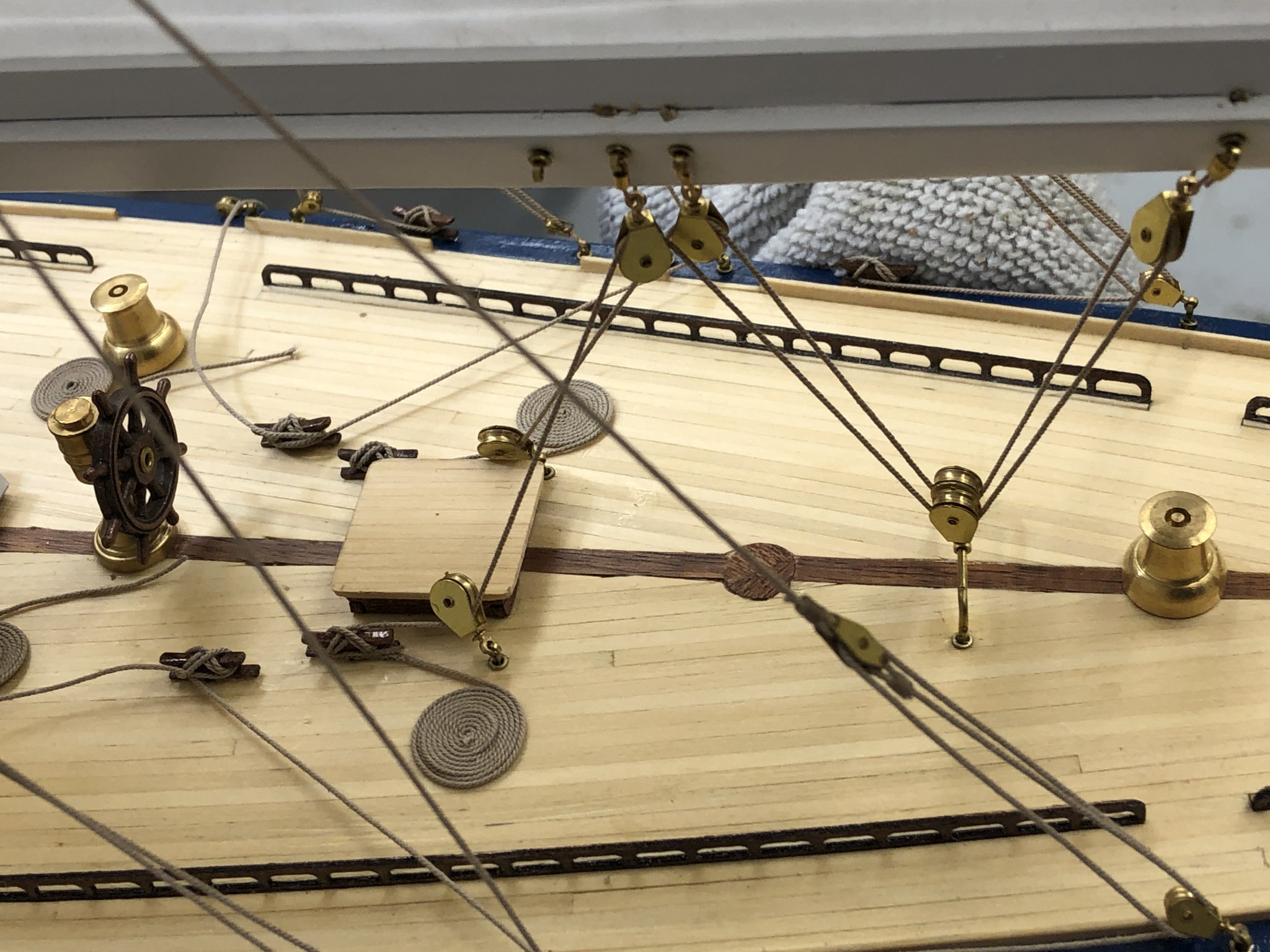
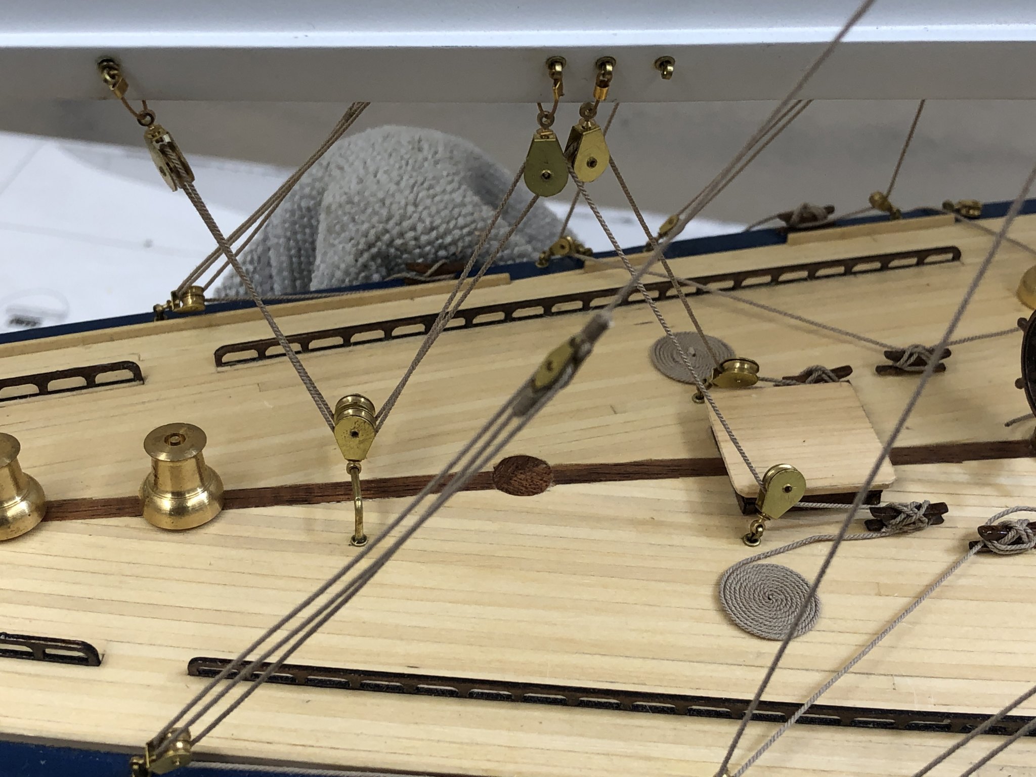
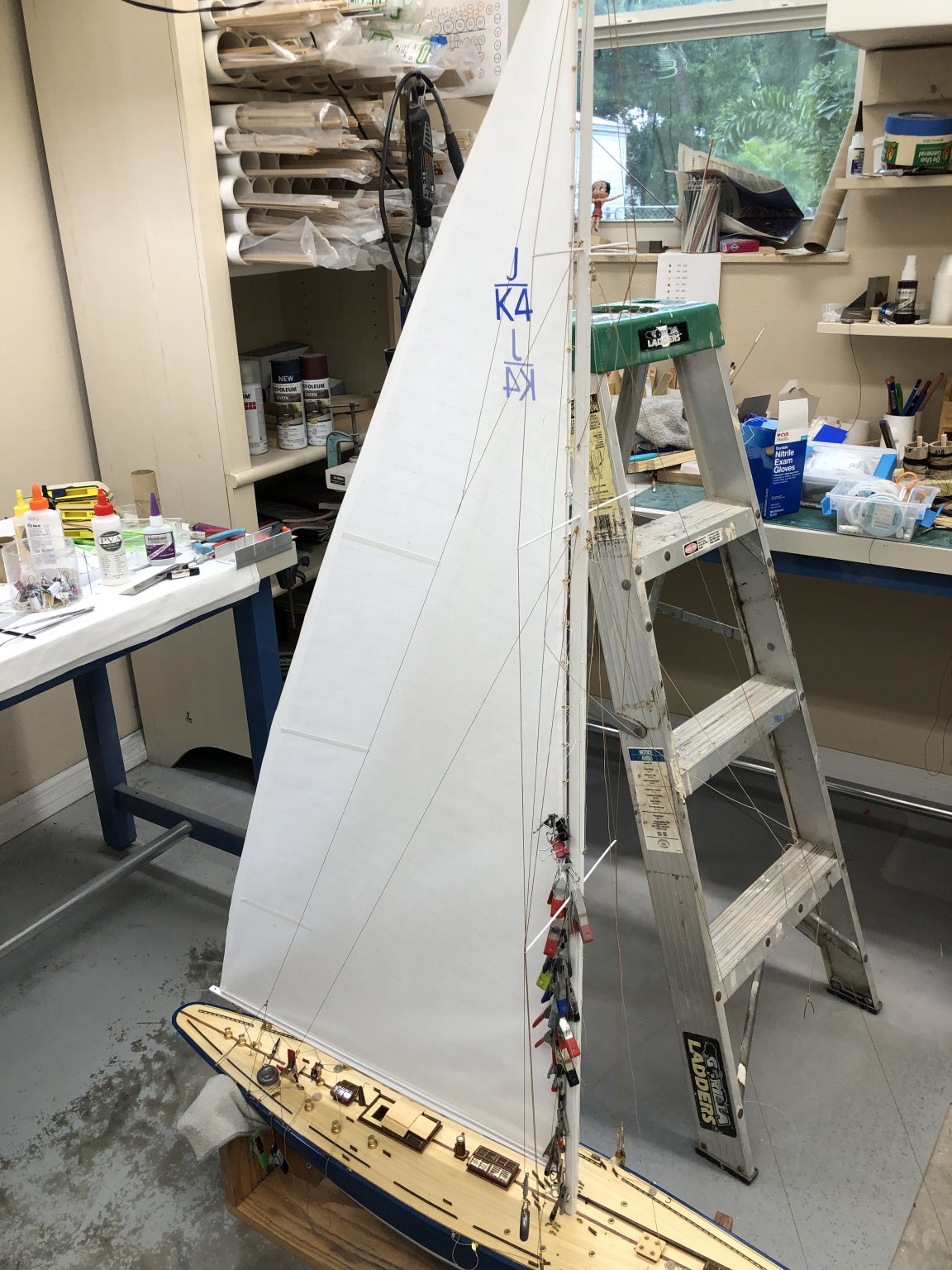
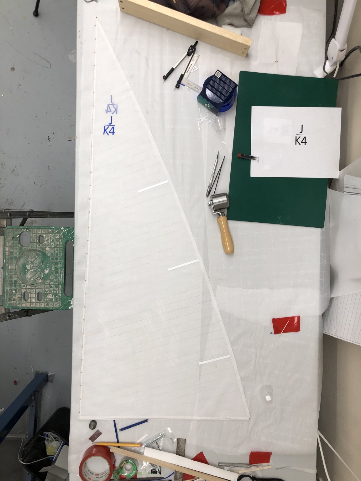
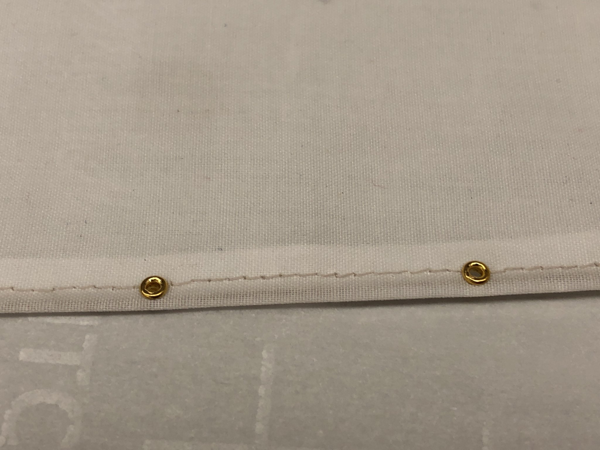
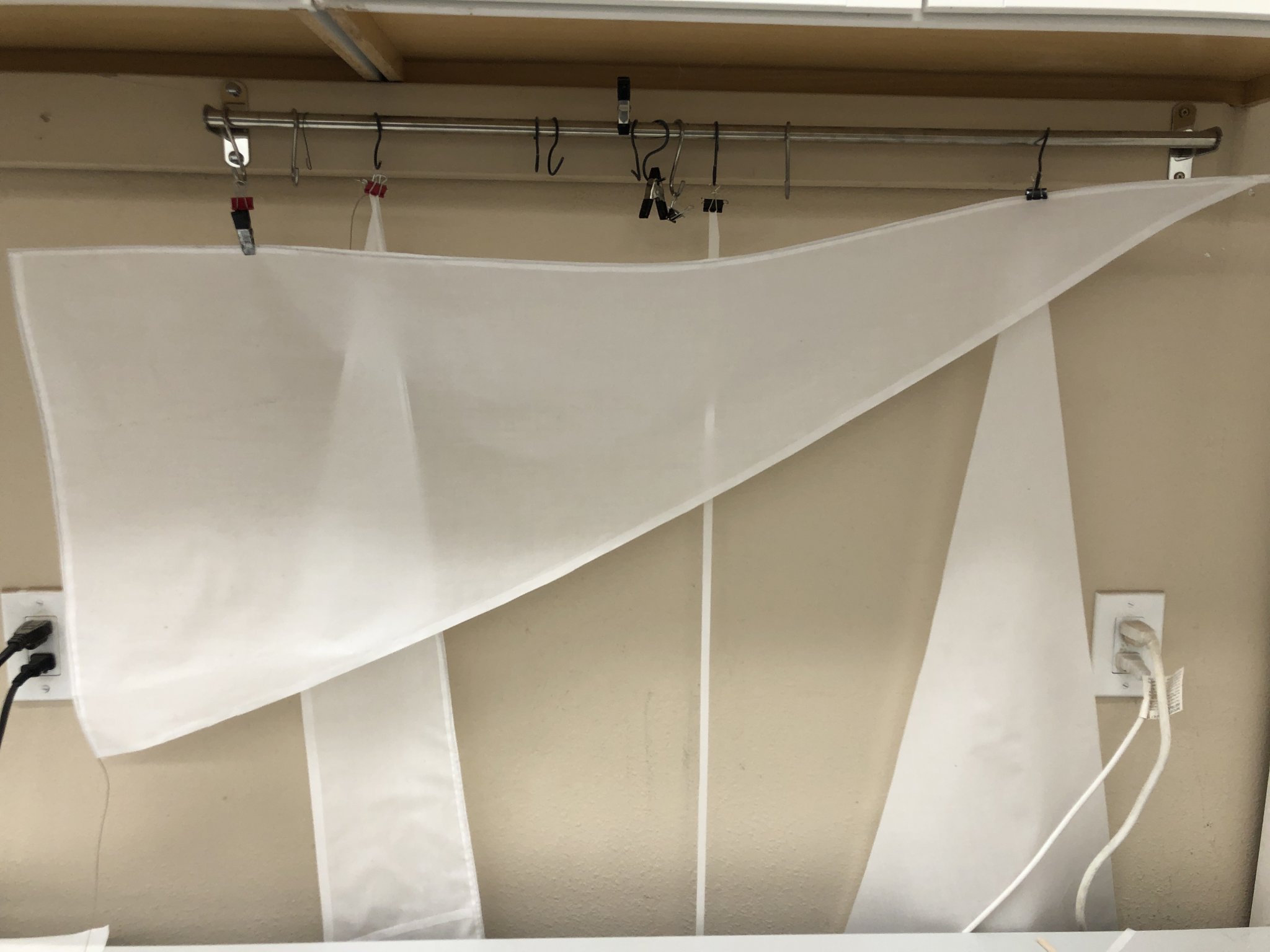
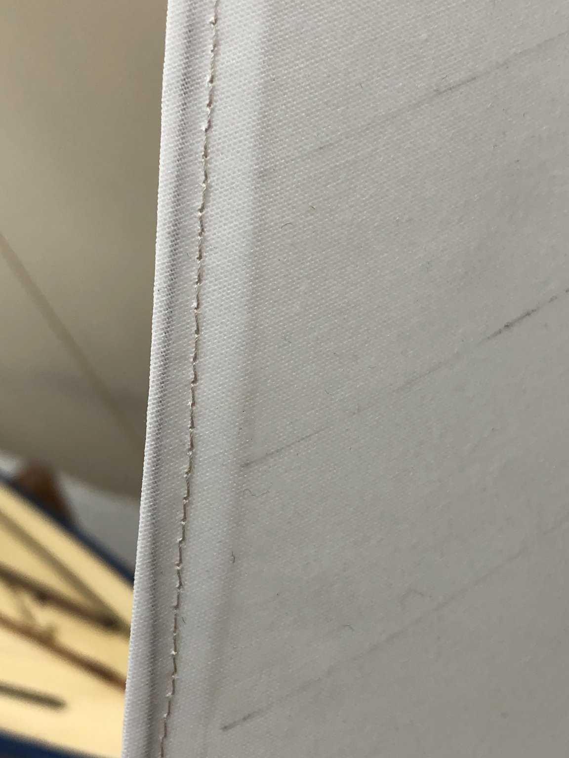
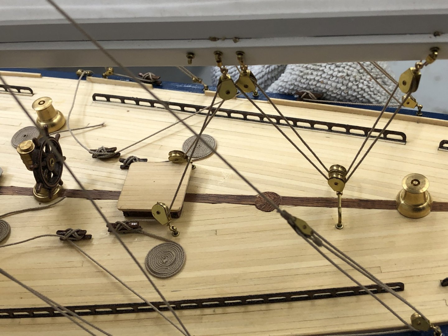
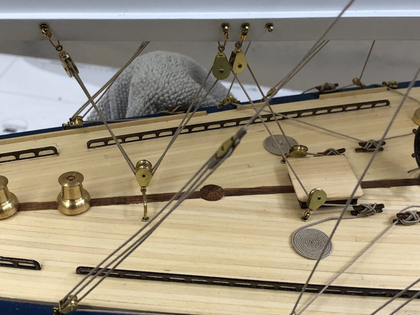
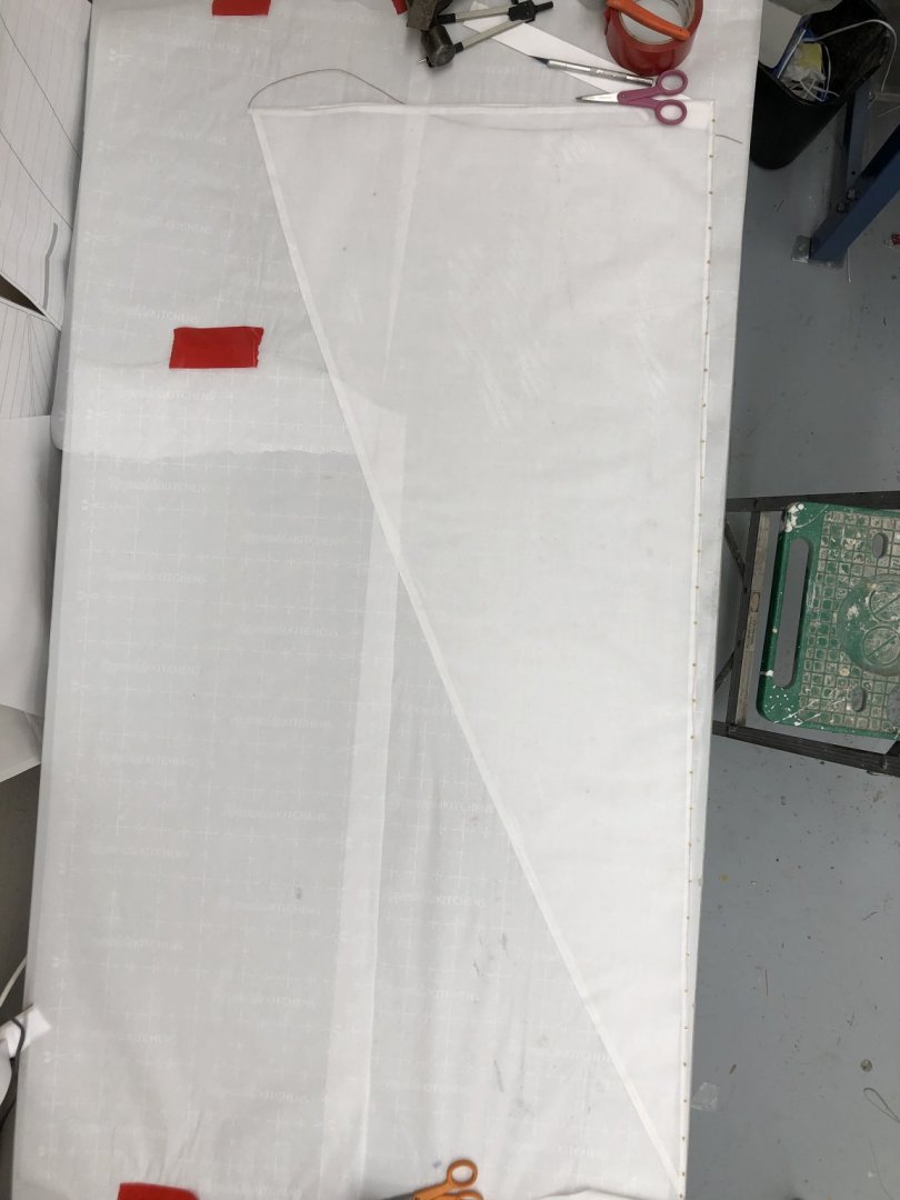
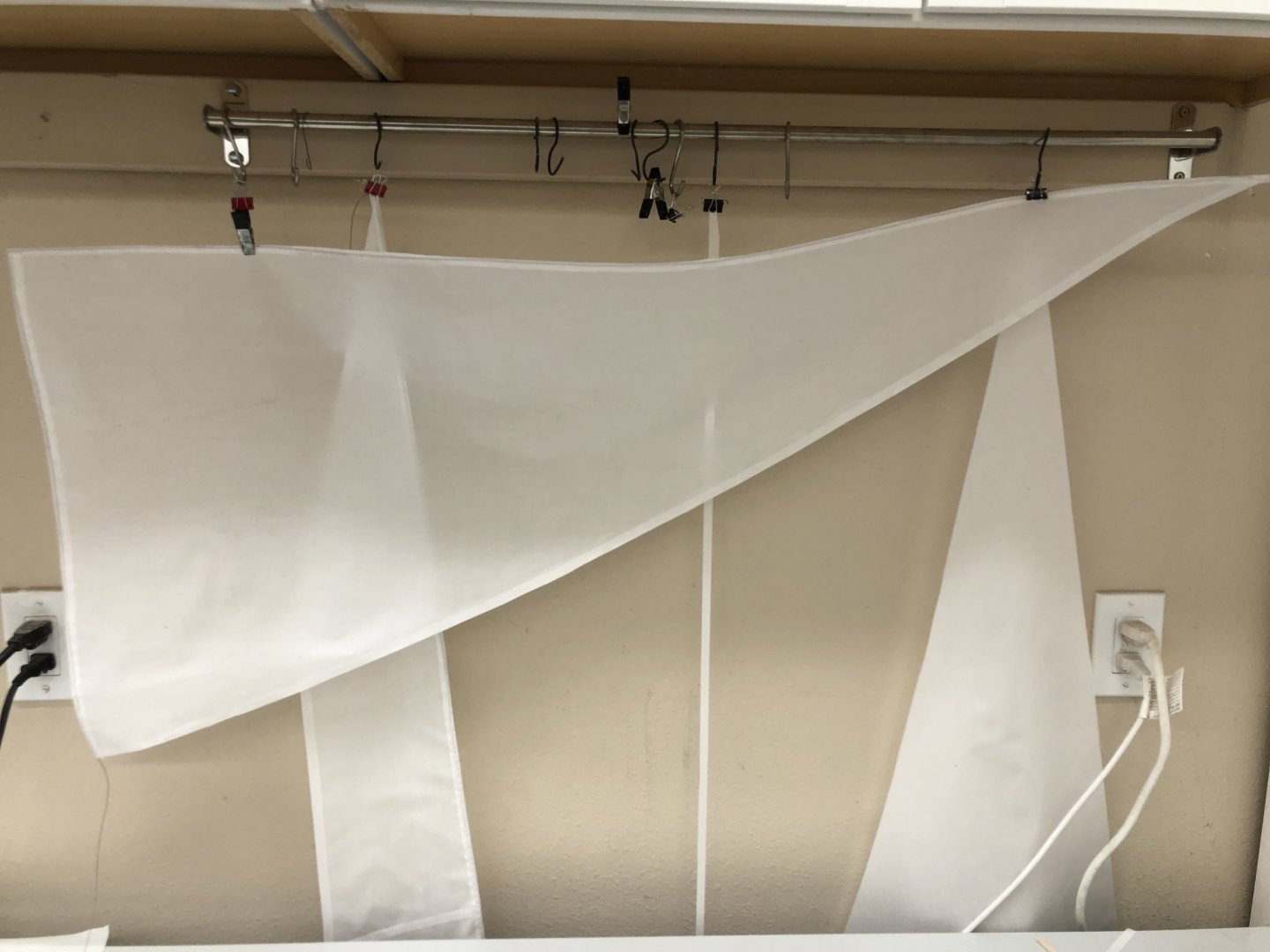
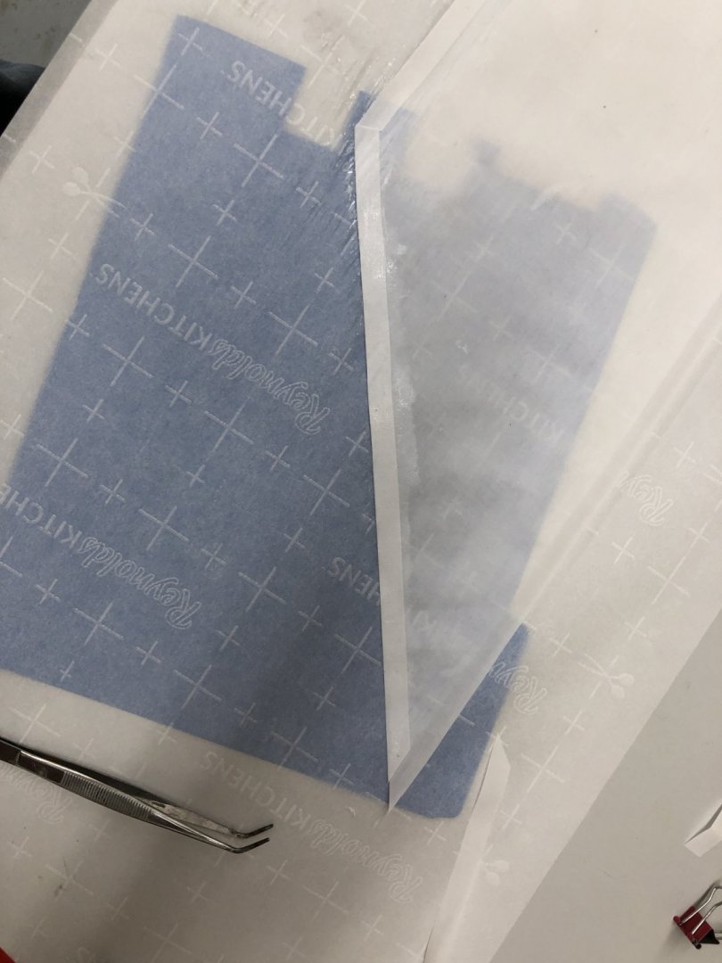
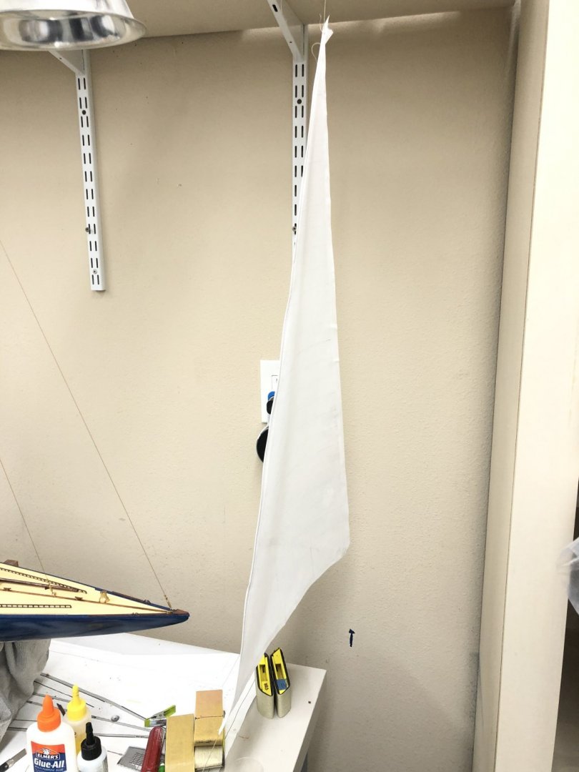
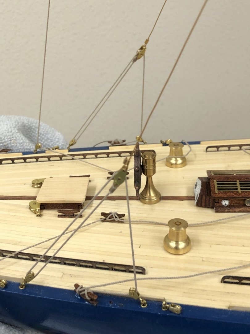
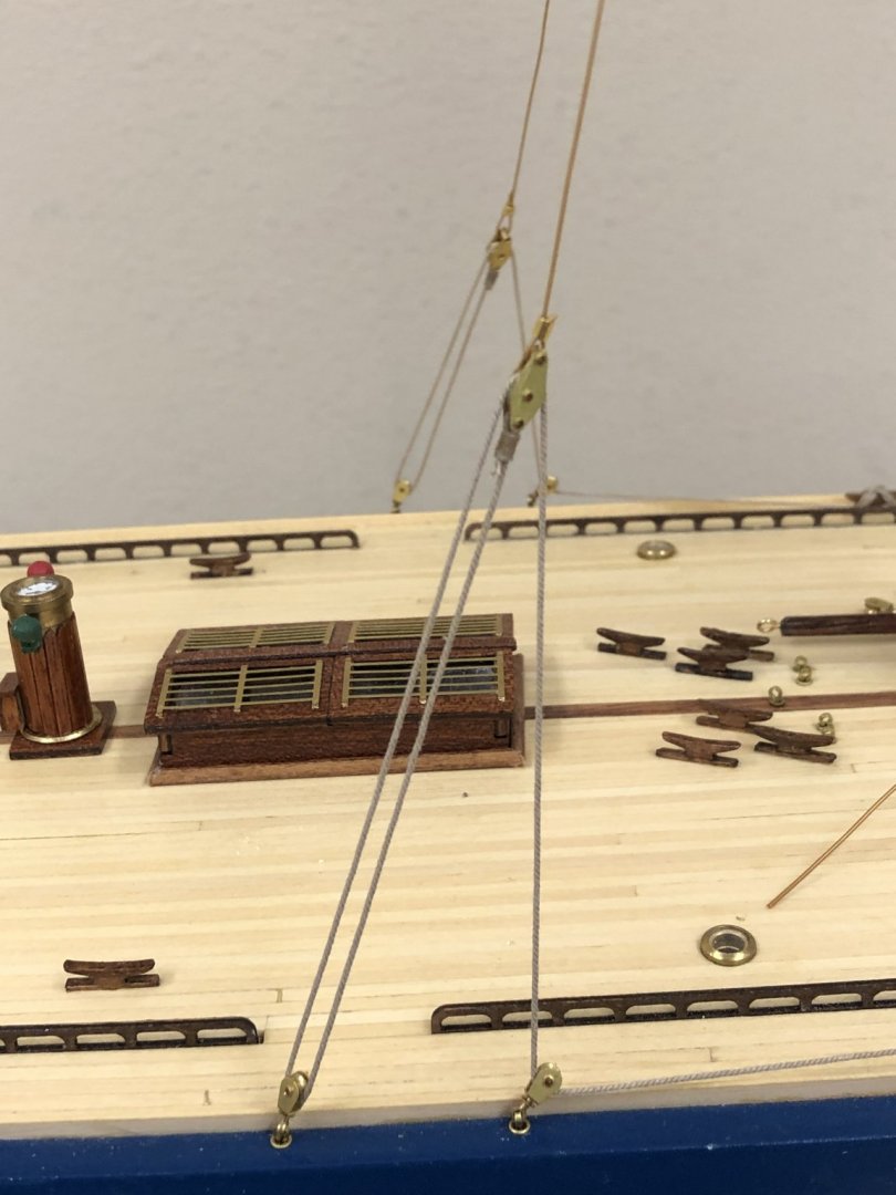
 Thanks Keith - need the ladder to see in the top most shelves of the cabinets - there are all sorts of forgotten items up there. 😀 I am gluing the main sail - mast connects 6 or so at a time using white (PVA) glue and letting each group set before moving to the next. I am trying to avoid moving the sail any more than necessary so as not to disturb the other connections to the mast. While waiting I recut a new jib since I am going to use brass eyelets and split rings the existing jib had to go. I used it as a learning experience as they say and there was plenty of already prepared sail material left over from the main which essentially used a bit more than half the rectangular sheet I prepared for it. Anyway, on this version rather than provide the seamstress (aka girlfriend) with a stiffened piece of line to sew into the luff as the bolt rope I decided to glue the line into the crease where the seam will be. I noticed on the other sails the bolt rope seemed to meander around inside the seam, sometimes close to the edge others further back. It makes getting a consistent distance from the eyelet to the edge more of a challenge than I had hoped. Anyway, now the bolt rope is firmly (hopefully) at the edge of the sail and it should be easier to sew the seam without having to contend with the rope moving around. Here is the new jib hanging up to dry after applying the reinforcing strips and gluing in the bolt rope. Also two shots (port and starboard) of the main sheet tackle with the rope coils in place (and glued down). I moved the cleats where it belays forward about 3/4" on both sides because I did not have much room between the fairlead block and the cleat. I probably should not have blindly followed the drawing for the cleat layout. The blocks I used are considerably bigger than those provided which probably accounts for the problem. I also should have moved the blocks on the boom further apart as they almost touch as they are mounted now, another example of blindly following the drawing after changing the materials. I may learn my lesson someday, but not today.
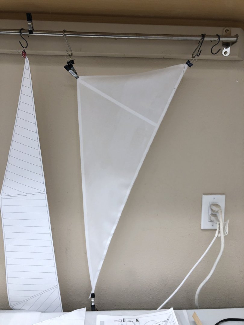
-
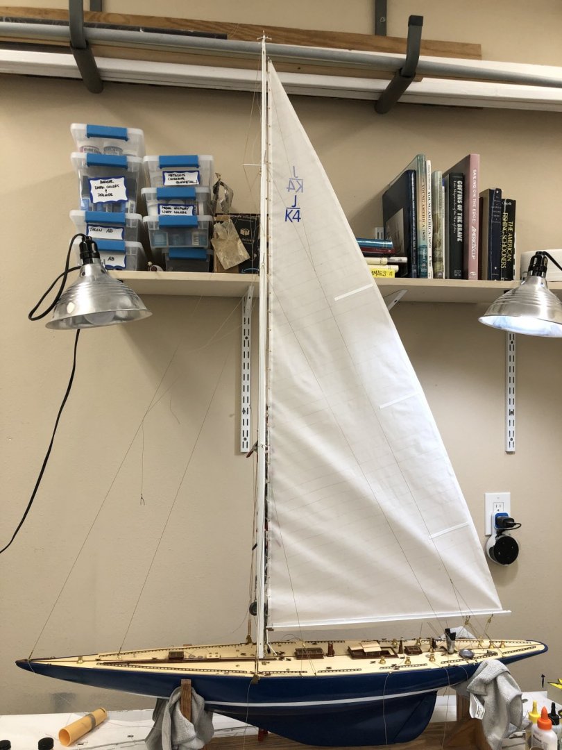
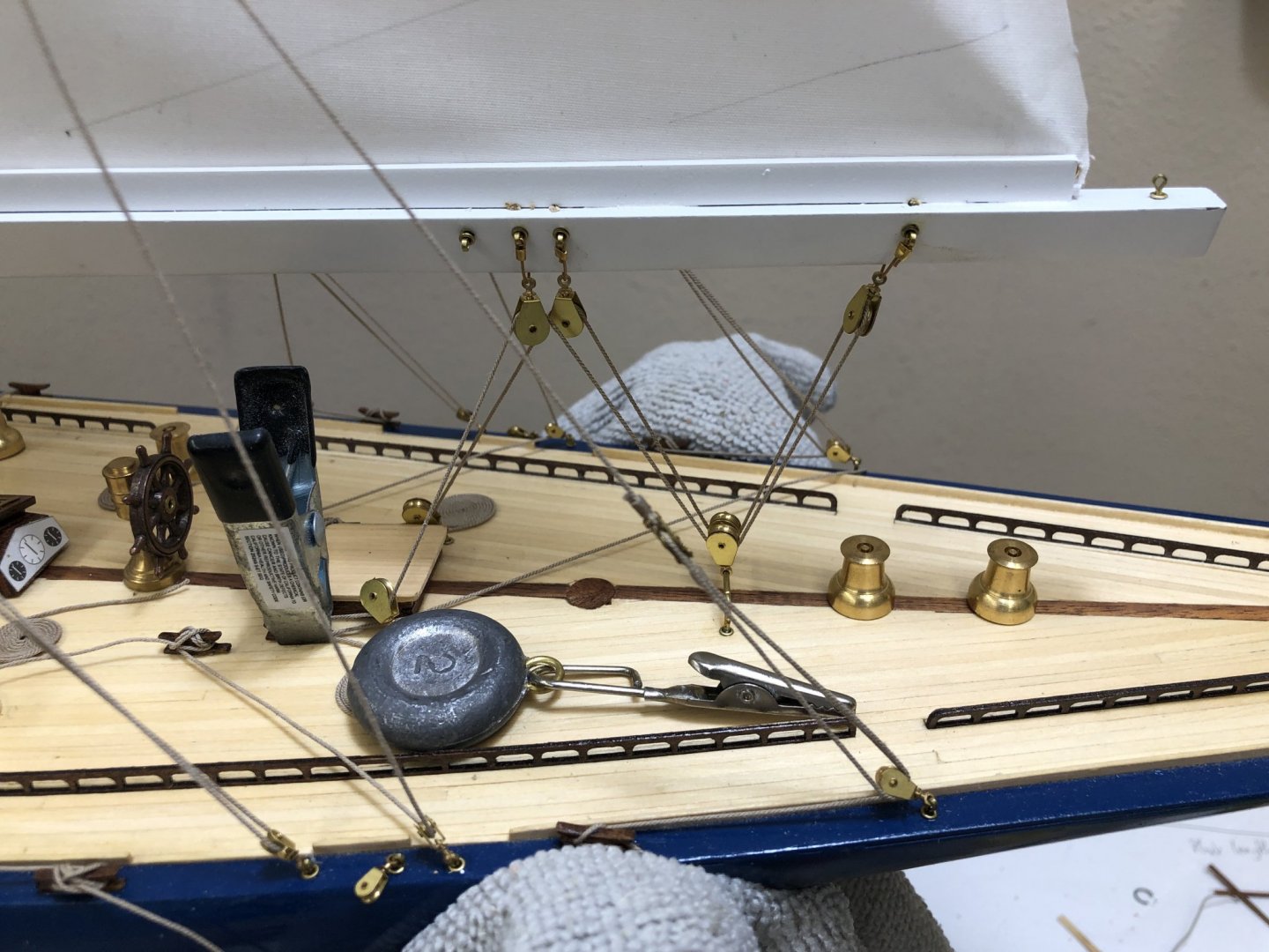
Finished with the main sail attachment and the main sheet tackle. Here is a shot of the port side. I suspect that the pronounced wrinkle starting at the aft end will relax as the sail and sheet tackle stretch out some. I put a good bit on tension in the sheet tackle to try and pull the sail away from the mast at the top. Now the lower attachment points are now below the mast eyebolts where they were more or less level until I tensioned the main sheet tackle. I guess "you pays your money and takes your choice." The starboard side is the one that will be the most visible as this will be displayed against a wall. Also a shot of the main sheet tackle. The clamp and weight are holding the sheet tackle and rope coil while they dry.
-
Rigging the main sail to the simulated mast "cars". I had to put the model on the floor as standing on a ladder to rig the last ten or twelve was too hard on my back.

-
Got the main sail mounted in preparation for securing it to the mast and rigging the main sheet tackle to the boom.
-
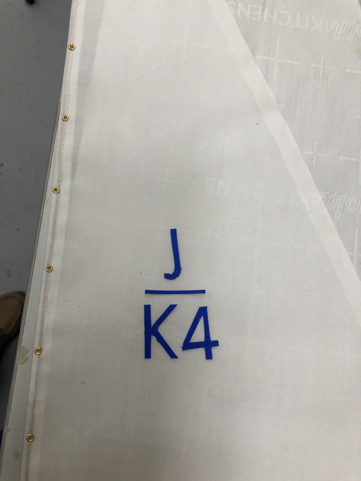
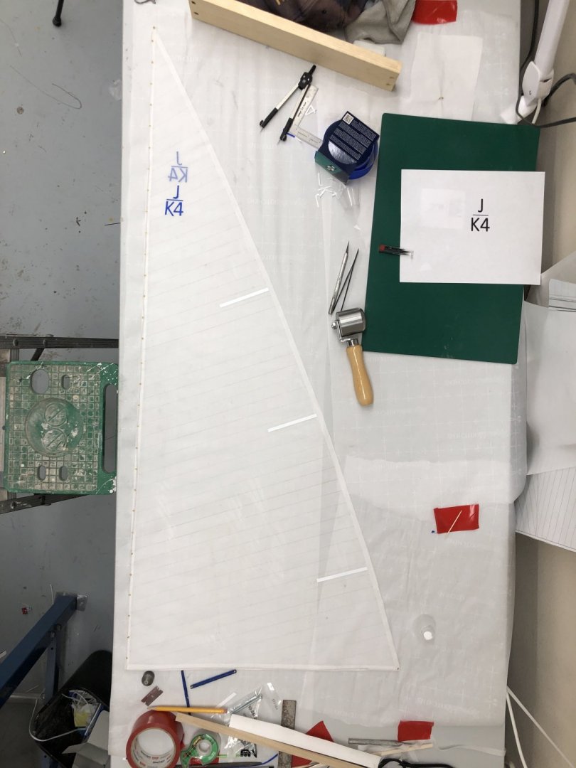
Thanks Keith - I decided to go with the penciled seams. Cutting about 100 1/8" stripes of spinnaker tape (and then getting them on straight) seemed "a bridge too far". And J/K4 it is. Main Sail is "finished". I just glued the battens on so that is why it is not onboard already. I used .010" X 1/4" Evergreen Strips for the battens. Based on the drawing they should be more like 5/16" but Evergreen only makes the really thin stuff max 1/4" width so that is what I used. What's a 1/16" (2.2 inches at scale) among friends. I used the fabric roller in the picture to try and make sure the numbers are firmly attached to the sail. To make the numbers I taped the template (in the picture also) to a piece of spinnaker tape which was also taped down and then using a brand new #11 Xacto blade and metal ruler I cut through the tape and backing. The hardest part was the curve on the "J". At close range it is still somewhat jagged. I am not sure the numbers are exactly where they supposed to be but they are close based on the limited pictures of the 1934 version I have been able to find. Will mount the main (and boom) tomorrow and begin to address the 30 attachment points.
-
I had to drive to Tampa and back to see a relative in the hospital so spent most of the day in the car (300 miles round trip). Decided to work on something "easy" this evening. Will tackle more sails tomorrow. I can only find a few pictures of the 1934 Endeavour and none of them show the sail numbers in any detail. You can tell there is something at the top of the sail but not what. Kieth Aug's Endeavour (although portraying the 1989 version) used J/K4 as the sail number and I am going to follow his lead. I cut the letters out of spinnaker repair tape (another Kieth Aug idea) and set them on the sail. I am thinking of ways (besides the adhesive that comes on the tape) to get these attached - I have a fabric roller coming so I am pretty sure I can get them on the fabric correctly. Am considering trying a glue/water mix or matte medium but will not do anything without an experiment. I am assuming that the numbers go on both sides of the sail but not directly opposite - one set is above or below the other on the opposite side. I am cutting another set out now (and maybe a third i9n case I screw on up getting it on the sail.

-
So here is my test of attaching the main using line and split ring. Both that a good bit of maneuvering the sail around. Can't iron again after this - it is "done". Still on the fence about how to proceed. Will sleep on it.

-
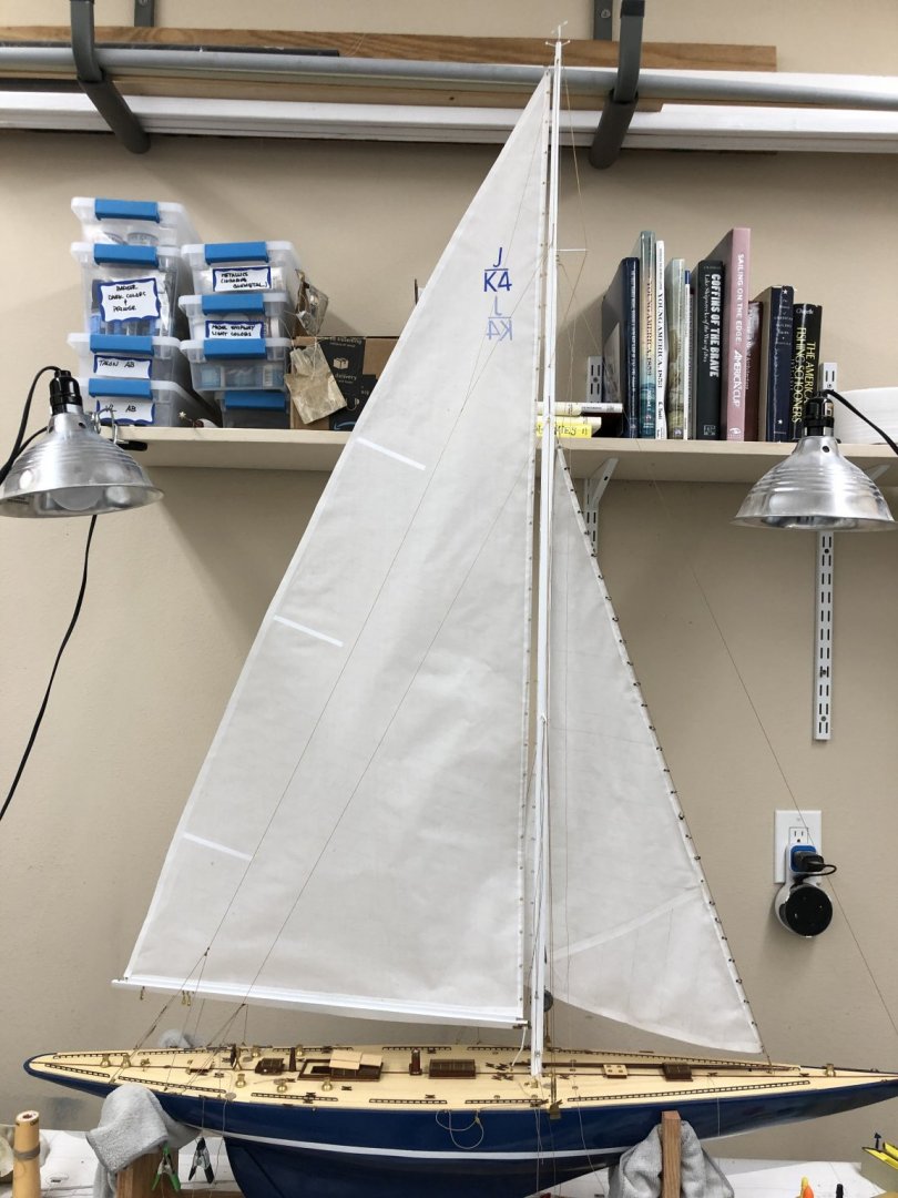
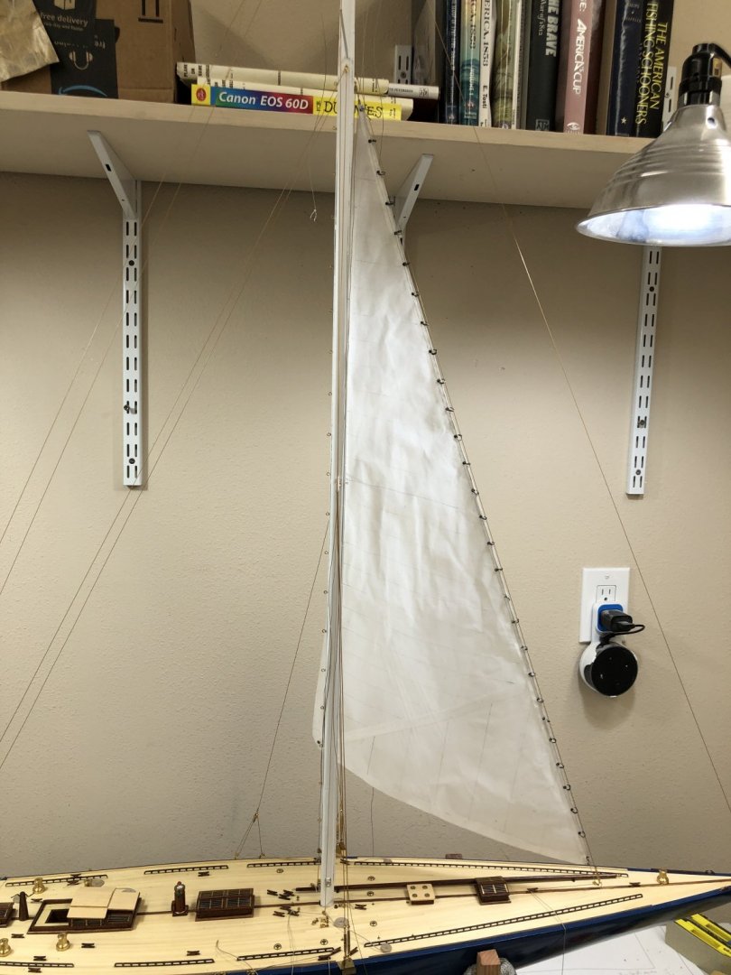
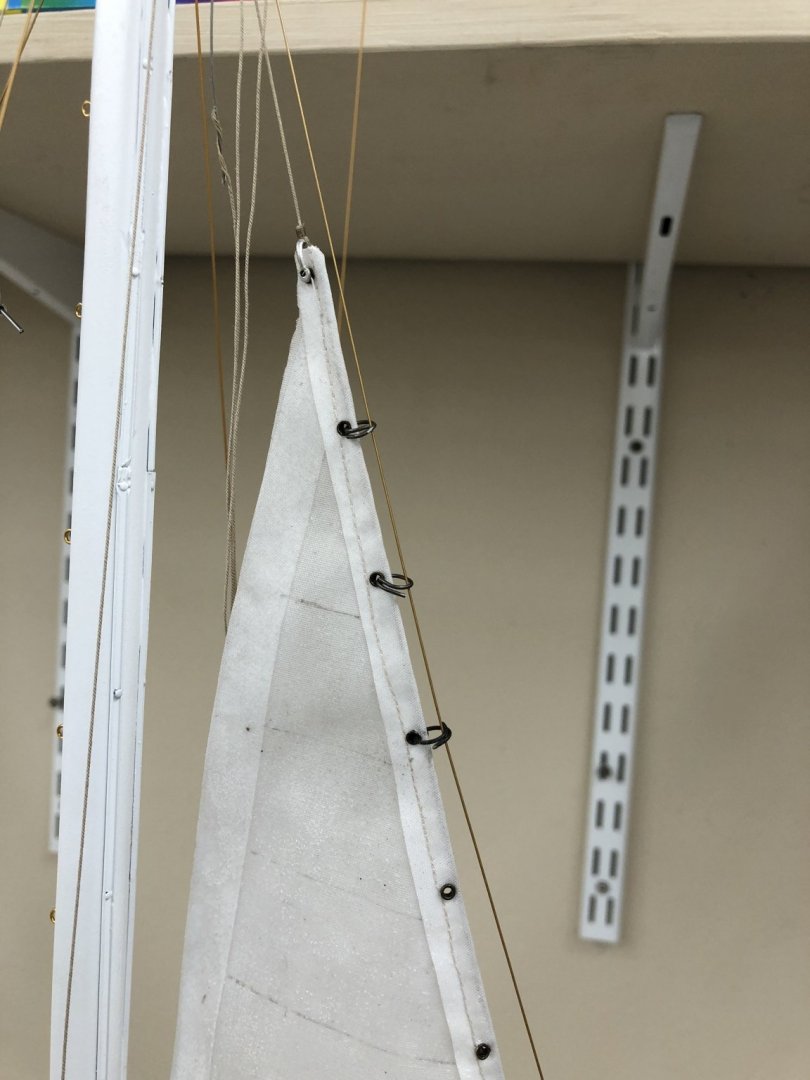
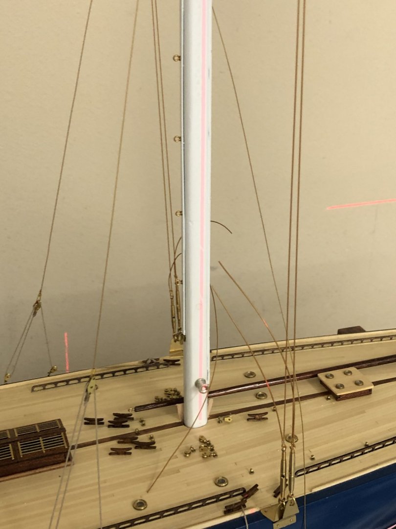
Two discoveries today. First the hardware from China for cutting holes and seating the eyelets leaves a residue on your hands/gloves which eventually ends up,on the sail, especially in and around the eyelet where you have to maneuver the fabric over the eyelet blank. This was quite evident with the jib so I covered the hardware with masking tape (blue painters) to try and eliminate/reduce the a=mount of dirt getting on the sail. Second, there is a similar residue that comes with the annealed steel wire. So I am shifting to brass wire for the split rings on the jibs. For the main I am still leaning toward using line - probably Bluejackets white .010 (of which I have several spools). I want to use white (rather than tan) so it does not stand out against the white sail. I need to try a test somehow. I managed to get all the eyelets on the main (31 of them) without a single episode of the guide pin sticking. Not sure why I had such problems using the antique brass eyelets, maybe it is different material. Anyway the main eyelets are done. I hoisted the main to mark where the eyelets had to go to match up with the eyebolts in the mast - see picture below. Looked pretty good. Not sure how the boom will sit with the sail secured but I really can't control that much so probably best to not worry. Now to sail seams. On the jib I used a pencil. On my model of Benjamin Latham I used 1/32" (or maybe 1/16") masking tape to simulate the seams in the sails. The sails (main and fore sail only) were made from silkspan (essentially tissue paper) and the sails were furred on the booms so not much of the seams showed and the sails had been colored closer to the color of the masking tape. I bought a roll of spinnaker mending tape colored blue to use to put the sail numbers on the sail and though it might be possible to cut thin (maybe 1/8" which would be a little over 4" (4.3 to be close to exact)) strips of the spinnaker tape (in white) to use to simulate the seams in the sail. From the back side all you see is the shadow. Not sure how it would look on the front side. I have some spare sail material (already coated with glue/water) I will have to do another experiment. My fear is that over time the adhesive would pull away from the sail material and it would look terrible. I have no idea how sticky (or long lasting) the adhesive in the spinnaker tape might be. You would think it would b e pretty sticky since it has to stand up to a pretty unforgiving environment and customers who are not known for being of a forgiving nature. Anyway here is the boat with the main and jib in place (more or less) and two shots of the main with the eyelets in plac e.
-
I have decided to delay any rework of the jib and shift attention to the main. I need to get it on the boom and the boom on the mast to establish where, exactly, the eyebolts on the mast would fall on the sail so the eyelets are in the right place. I had been considering using brass for the main eyelets anyway and using white line to link the eyelet and eyebolt instead on a brass split ring as my experience with the jib shows that can lead to excessive handling of the sail. Not sure rope would be easier/less handling but I will at least try that for a few to see how it goes (and looks).
-
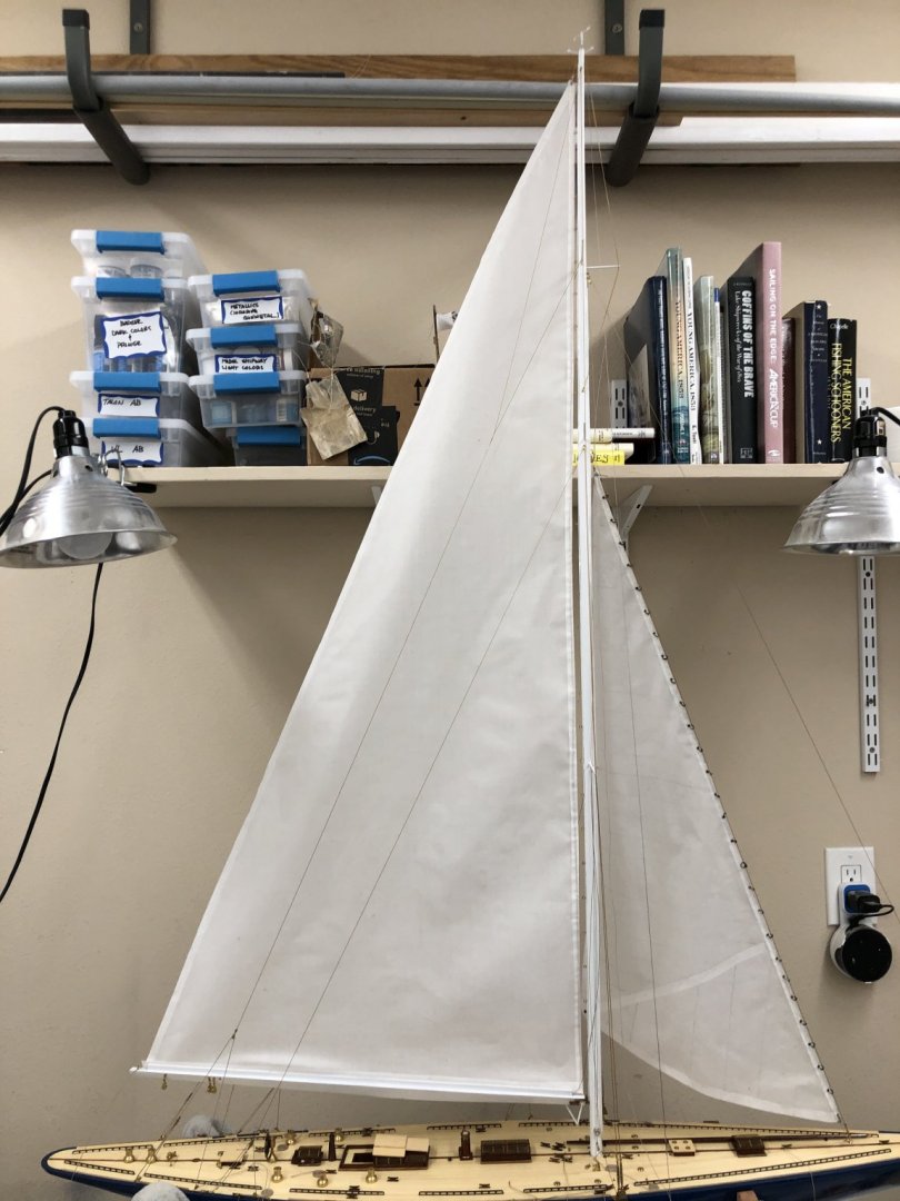
Jib is up! But it doesn't look as good as I had hoped. First mistake I think is that I should have ironed it one more time just before I threaded it on the stay. The other mistake I think is I should have put the jib on a new wire and re-rigged the stay with the jib threaded on - that would make handling the jib, which is bound to put wrinkles and potentially other damage at a minimum. That and two of the eyelets came out of the fabric while I was threading the hank on the stay. Reconsidering my next move, possibly cutting the stay to get the jib down, ironing, replacing the eyelets that pulled out and then replacing the stay with the jib already threaded on. Also thinking maybe redoing the hanks using brass wire instead of the annealed steel. In spite of wearing exam gloves while handling the hanks I think the sail got dirtier from the annealed wire which is not the cleanest stuff to deal with. Making hanks is pretty easy now that I have "the system" down.
-
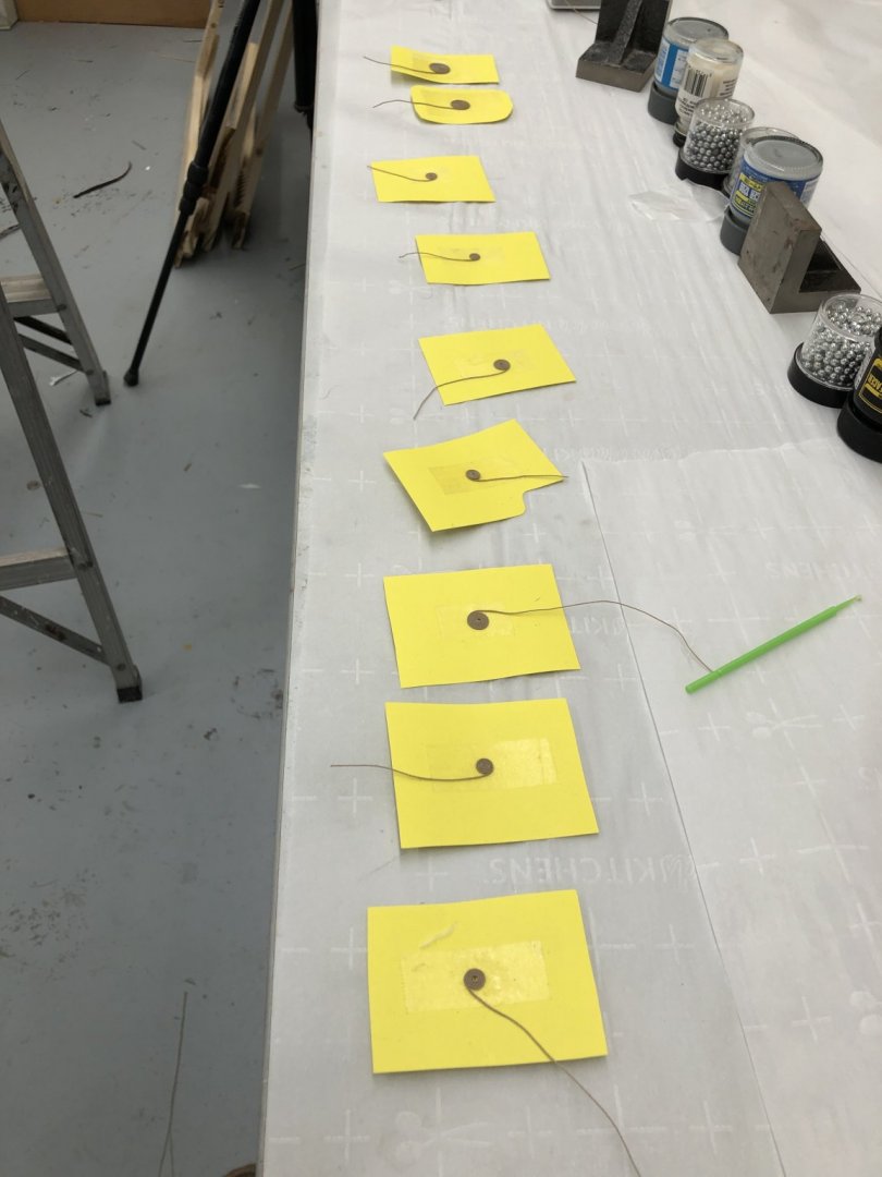
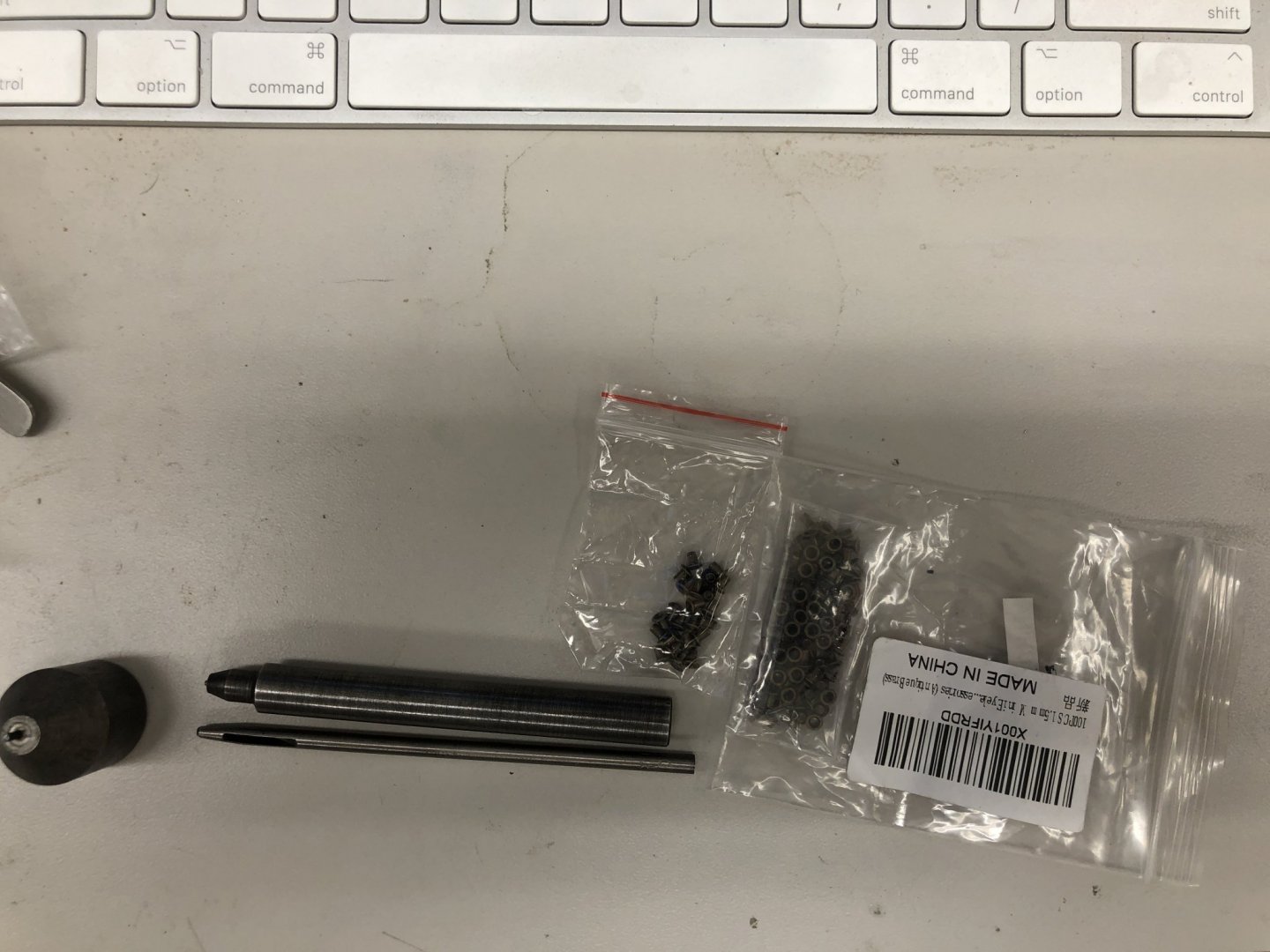
As for the other sails, they are finished except for the seam marking (H hardness charcoal artist's pencil) and the eyelets. Speaking of eyelets, the cheapy Chinese eyelet installation hardware lasted through doing the jib eyelets but had to be repaired four times. The little pin that holds the eyelet keeps sticking inside the mandrel and without the pin returning (there is a spring in the mandrel that in theory would force the pin back out after the eyelet has been seated) you can't do another eyelet. It seems the metal on the head of the mandrel gets distorted and the pin hangs up. At the end I resorted to taking a file to the pin (which also gets distorted) to try and remove any burrs but still had to take it apart after every two or three eyelets. I have a new set coming today that hopefully (given what I know now) will last me through the flying jib and main but am considering ordering another just to be on the safe side. Here are the two sails patiently waiting for attention. There is also a spare piece of sail cloth that is big enough to become the jib if something happens that makes me have to redo it. I decided to take one sail all the way through the process in case there are some lessons to be learned that can be applied to the others (like ordering additional eyelet hardware). I also busied myself during football on Monday making rope coils. Here they are dry and ready for removal from the double sided tape that holds the coil while the 50/50 glue/water dries. The other things in the picture are used to weigh down some of the coils while they dry to keep them from becoming "dished".
-
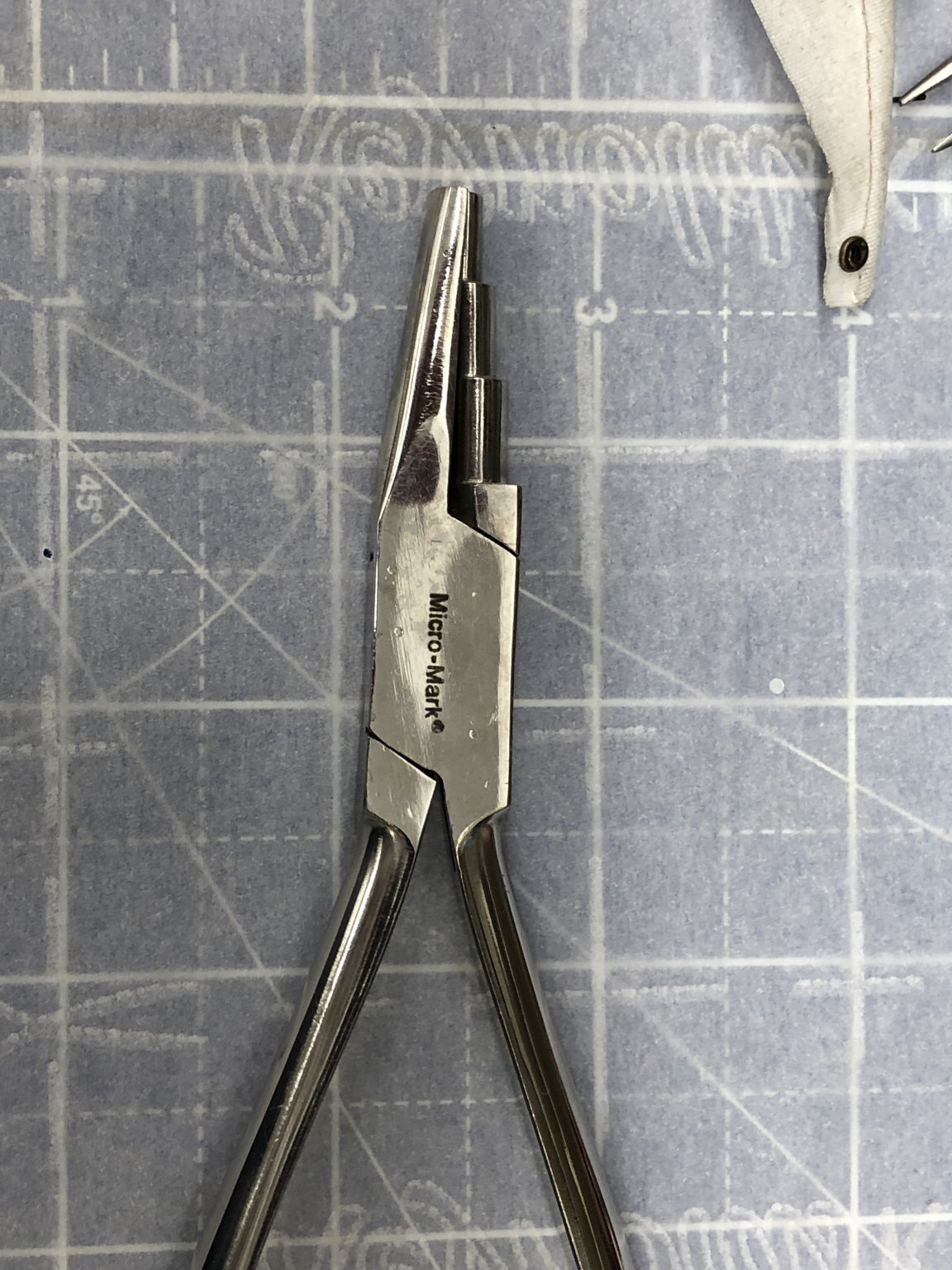
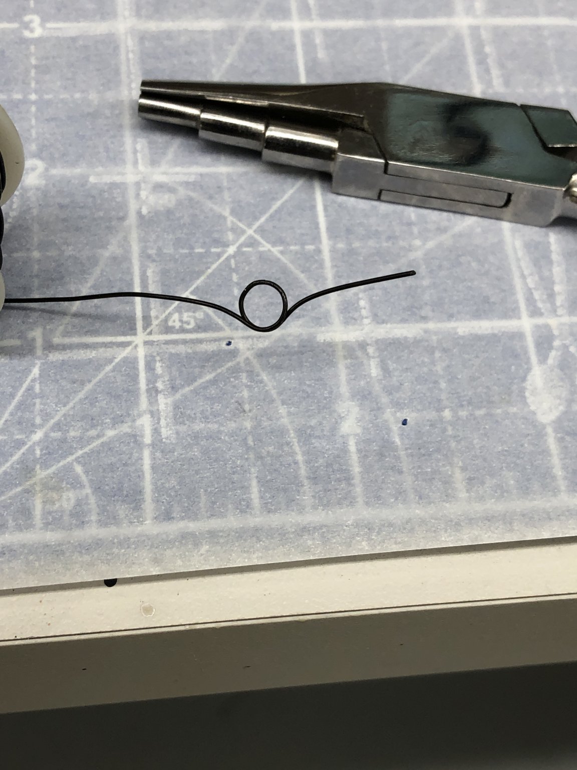
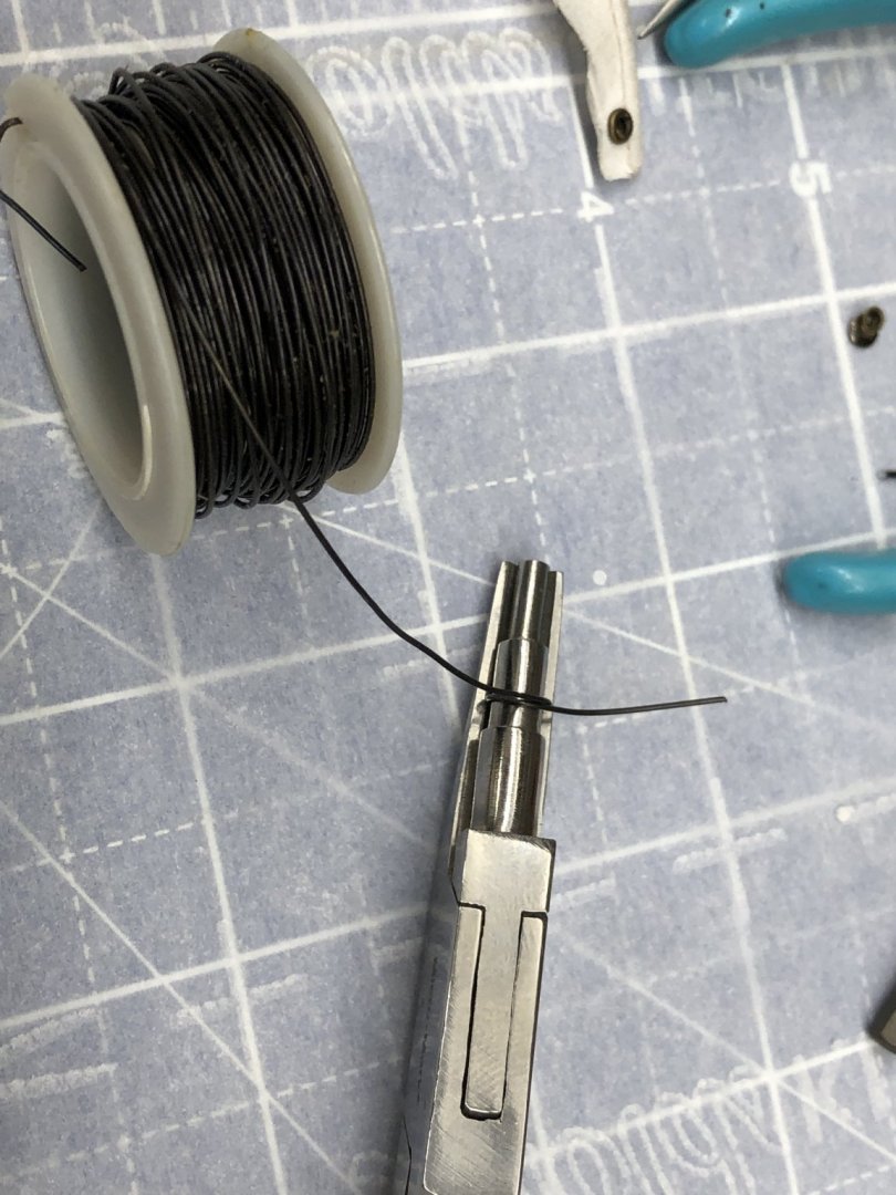
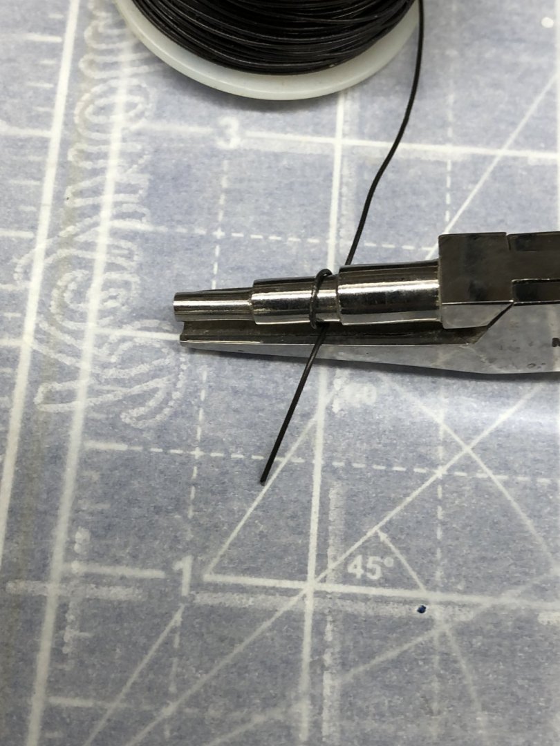
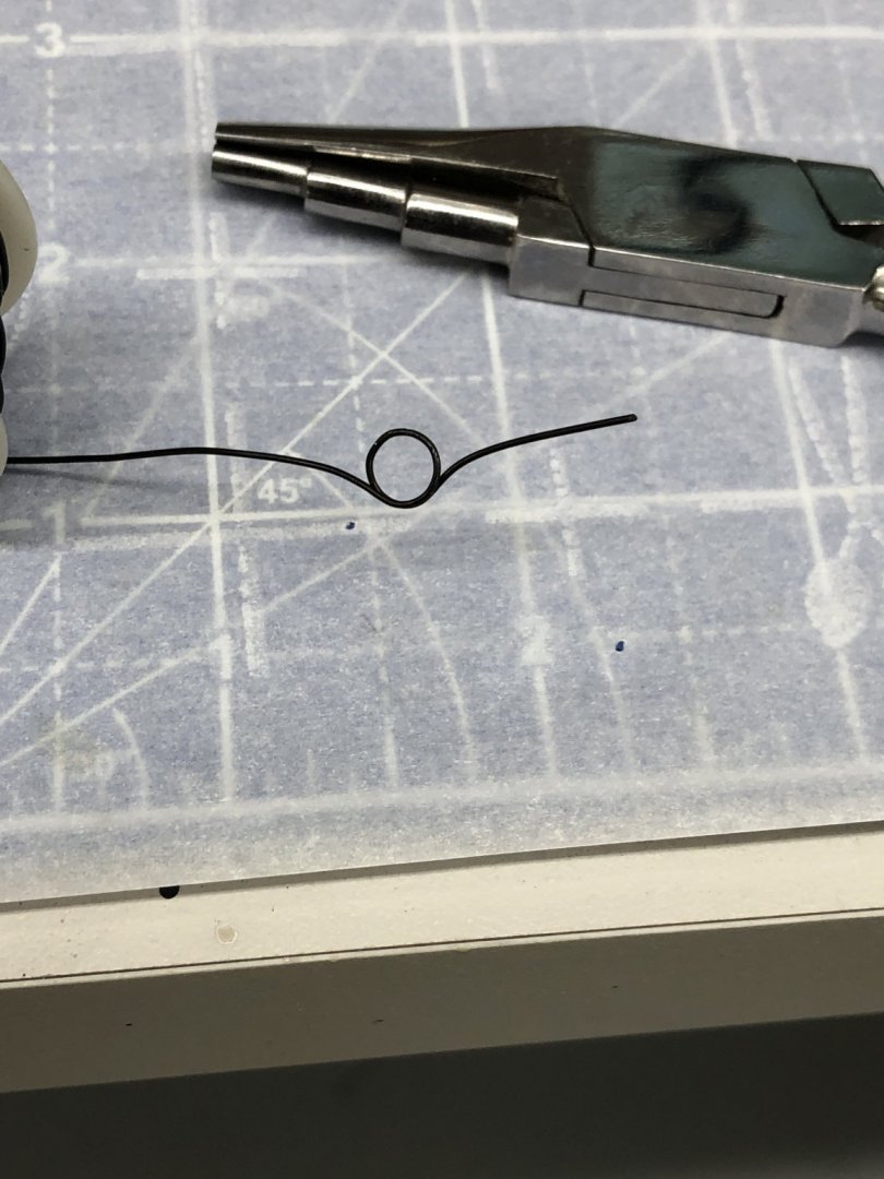
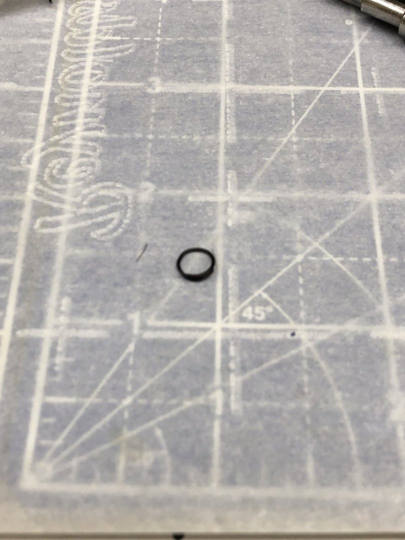
Making Jib Hanks The instructions and material provided would use simple brass split rings (the ones with no overlap - just the two ends butted together) for the jibs hanks (and on the main as well). My experience with these is that I can never get the gap closed up again as well as it was when I started and thus keeping the split ring on the stay would likely be a continuing challenge. As I get three on one of the previous ones slips off, when I put that one back another slips off, etc. etc. So I decided to make my own. I use 24 ga (.020: diameter) steel annealed wire (I think what I have came from Bluejackets) and the Micro Mark wire "bender" (see picture) on the middle (3/16") barrel. I make a ring until the ends cross, then reverse the "bender" and complete the ring with the wire overlapping itself. I trim the end cutting at an angle close to the ring and end up with a 3/16" split ring with the ends overlapping about 25% of the circumference. This makes it more difficult to get onto the sail but much less likely to slip off the stay. I apologize in advance for the pictures not being in the correct order (unless by some miracle they are).

-
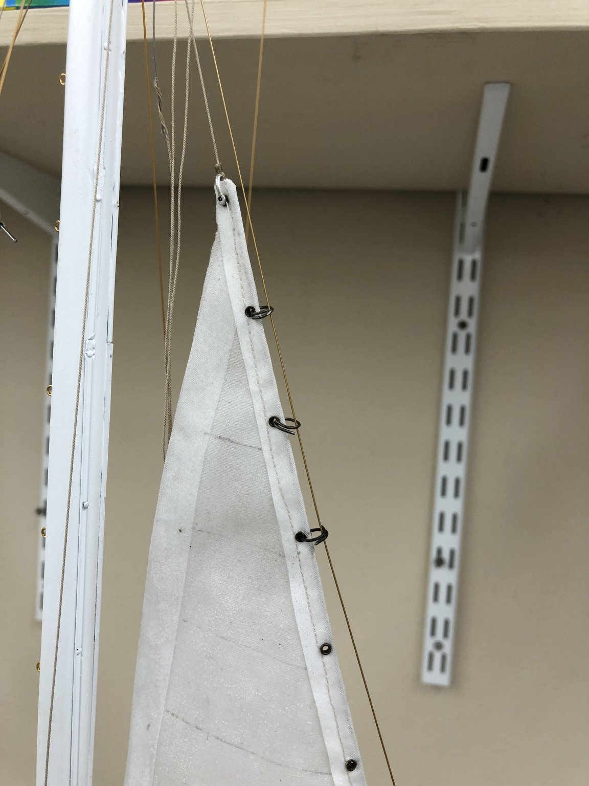
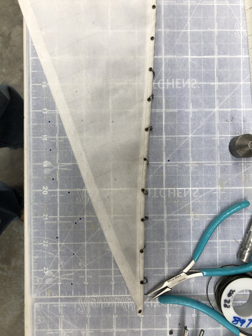
So where are we now? I have the jib completed - all the eyelets are there just manufacturing jib hanks to get it on the boat. So, at first I hung the jib from the halyard, made a few hanks and started to install them on the sail and stay. That didn't work out so well as getting the hanks (at least the ones I designed-more on this later) onto the sail proved to be more difficult than I expected. So I took the jib down and am putting the hanks, as I make them, on the sail. When I have them all done THEN I will hang the sail on the halyard and try and get the hanks on the stay, which should be much easier than getting them on the sail - at least I hope so. Here are pictures of the first attempt and where I am now, about 25% done with the hanks.
-
Julie - no problem; I have read your build log (and Kieth's) from end to end and picked up some good tips that helped me get this far. Good luck getting to the finish line.
-
Having read some of the reviews of the eyelet "tools" and having had to take the anvil apart once already after only 4-5 test eyelets I ordered another set (they are less than $15 on Amazon) and a 2mm set as well since at least one person said the setting tools for the 2mm works better than the 1.5m tool on the 1.5mm eyelets. They all should be here tomorrow. In the mean time I have the reinforcements on the main and am waiting for the stiffened line for the bolt rope on the main and flying jib to harden so the "seamstress" (aka girl friend) and sew them into the seams.
-
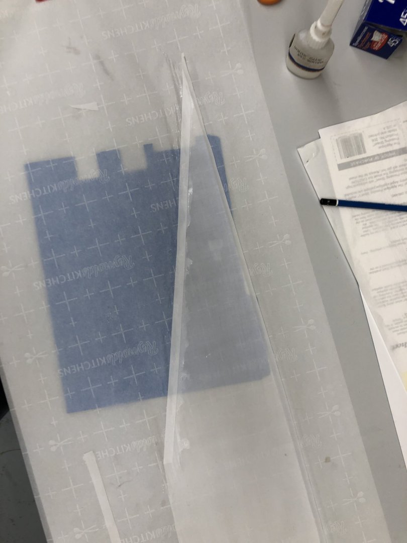
Working the Flying Jib, then on to the Main sail. Lesson learned from the Jib. Use gloves (cheapy nitrile exam gloves) when working with the fabric. Especially with the white sails - every bit of dirt around seems to find its way to my figures and then to the sail. I cut the Flying Jib per the pattern that I validated for correct size on the model using a cutting board, ruler and cutting wheel from the quilt czar (aka girlfriend). I also cut two strips 3/8" wide to make the reinforcements from. The blue file folder I used to help see when I had the sail and the reinforcement lined up. I put a line of 50/50 glue water on the sail applied and aligned to strip and then put a line of 50/50 on the reinforcement strip. I smoothed things out trying to make sure there all air bubbles were removed. The eyelet "kit" has also arrived and it looks like this is going to work. The kit includes a punch to cut the hole and an anvil and tool to crush the sides down. Here is my first try on my test strip. These will good in the seamed edge of all three sails - I counted 31 on the main, 28 on the jib and 35 on the flying jib. Good thing I got 125 eyelets in antique brass. I am not sure I can get the eyelets close enough to the sail edge to use the split rings provided in the kit plus I do not relish having to open and the successfully close 60+ split rings. I will see about making some jib hanks from annealed steel or maybe brass wire.

-
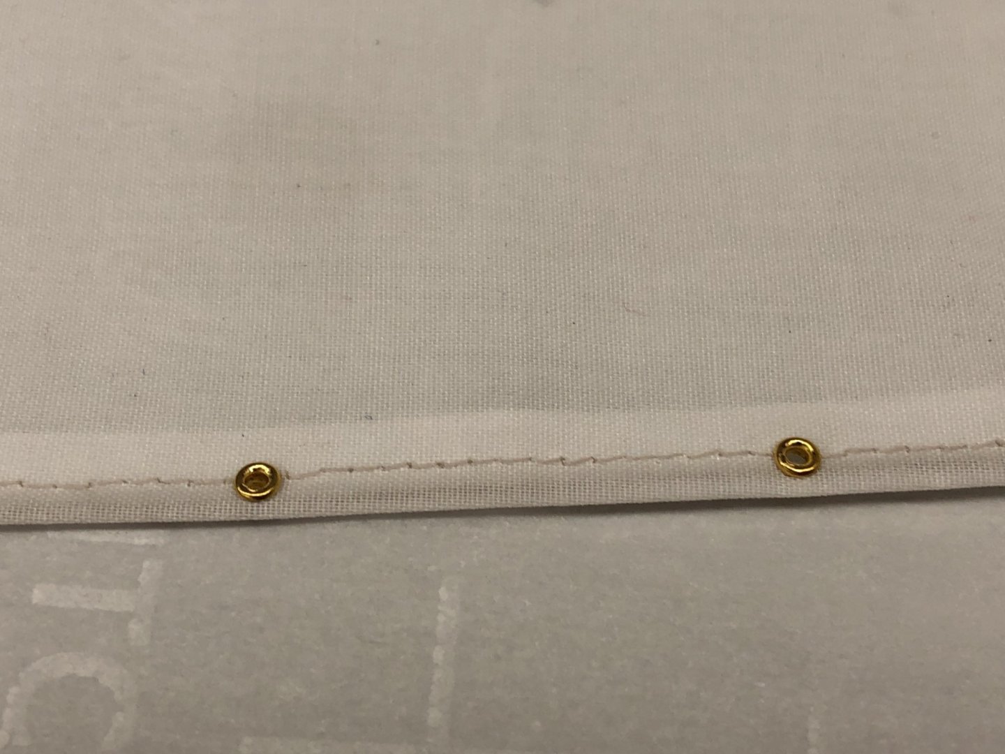
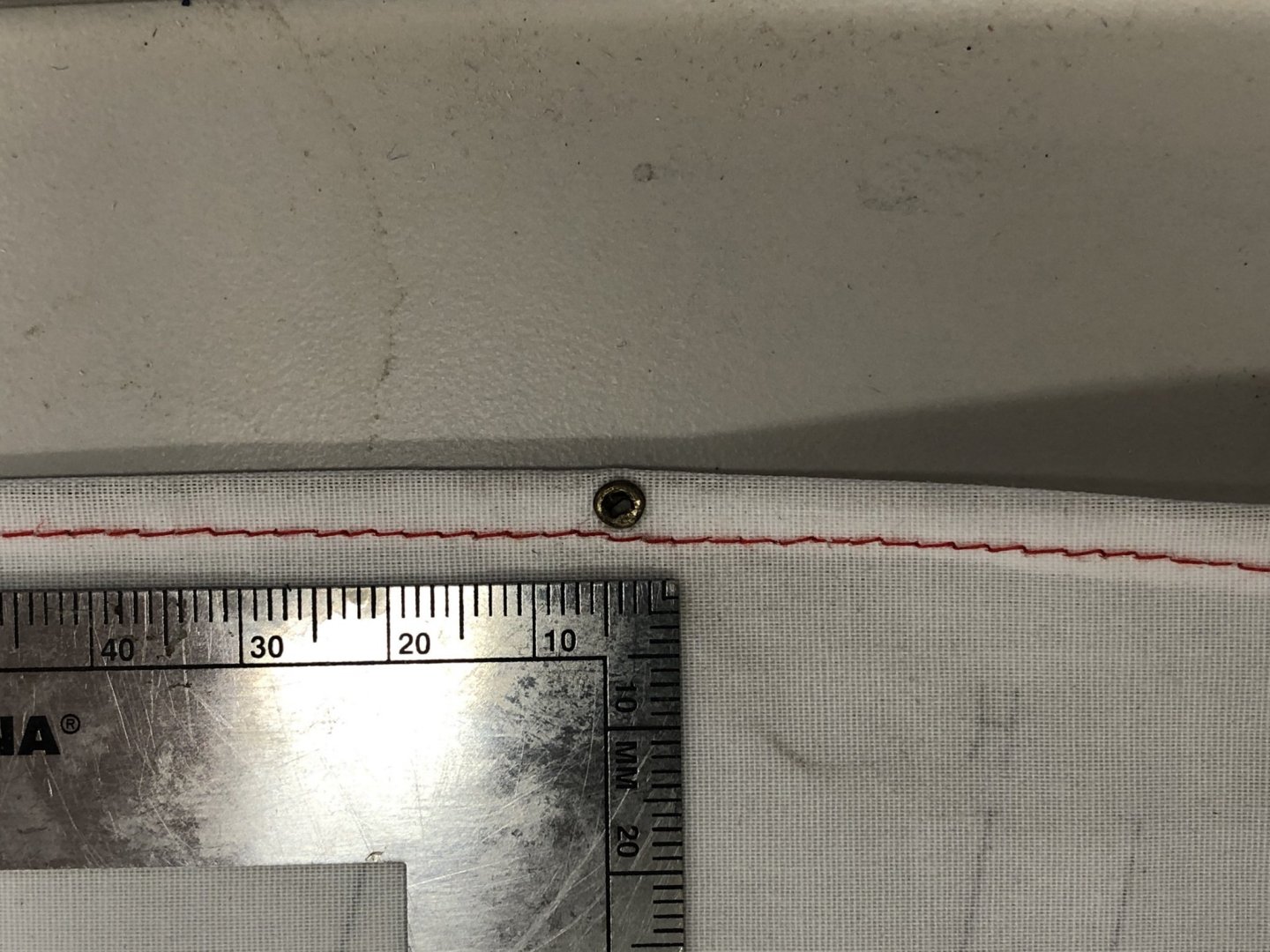
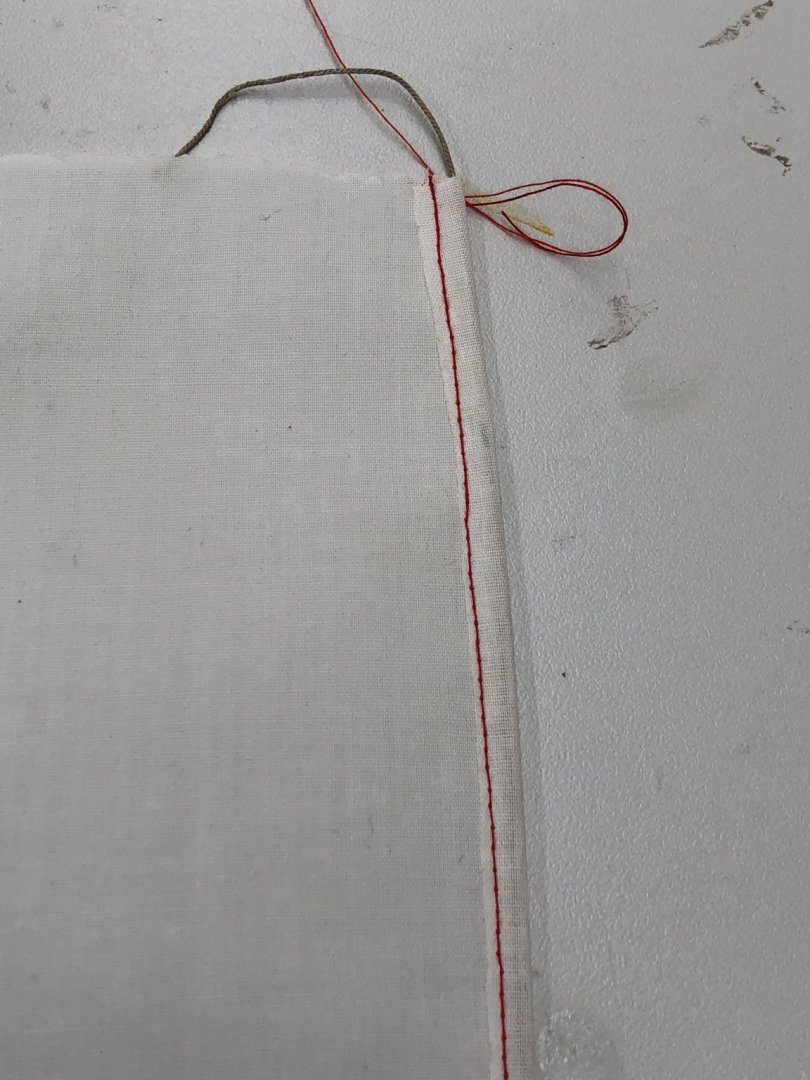
Working the jib as the first sail. Sort of a "test case". When I added the reinforcement strips at the leach, foot and one in the middle, i used the 50/50 glue water mix again with the sail on a piece of parchment paper to keep from gluing it to the table. That worked "okay" but there were a couple of places on the leech where the reinforcement strip did not stick (or I didn't get it in down exactly correctly. Anyway when the sail dried I noticed "watermarks" around the reinforcements. After the bolt rope was sewn into the sail I coated the entire sail with 50/50 glue/water to try and remove the watermark. The jib is hanging up to dry while I work on the flying jib. Here are pictures of the jib hanging to dry and the bolt rope seam.

-
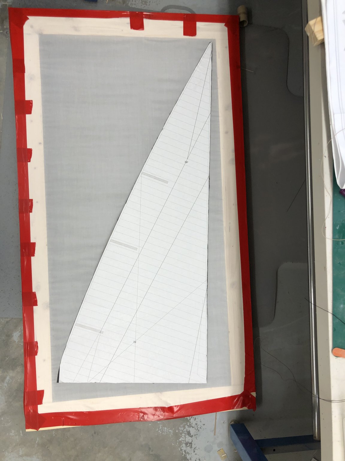
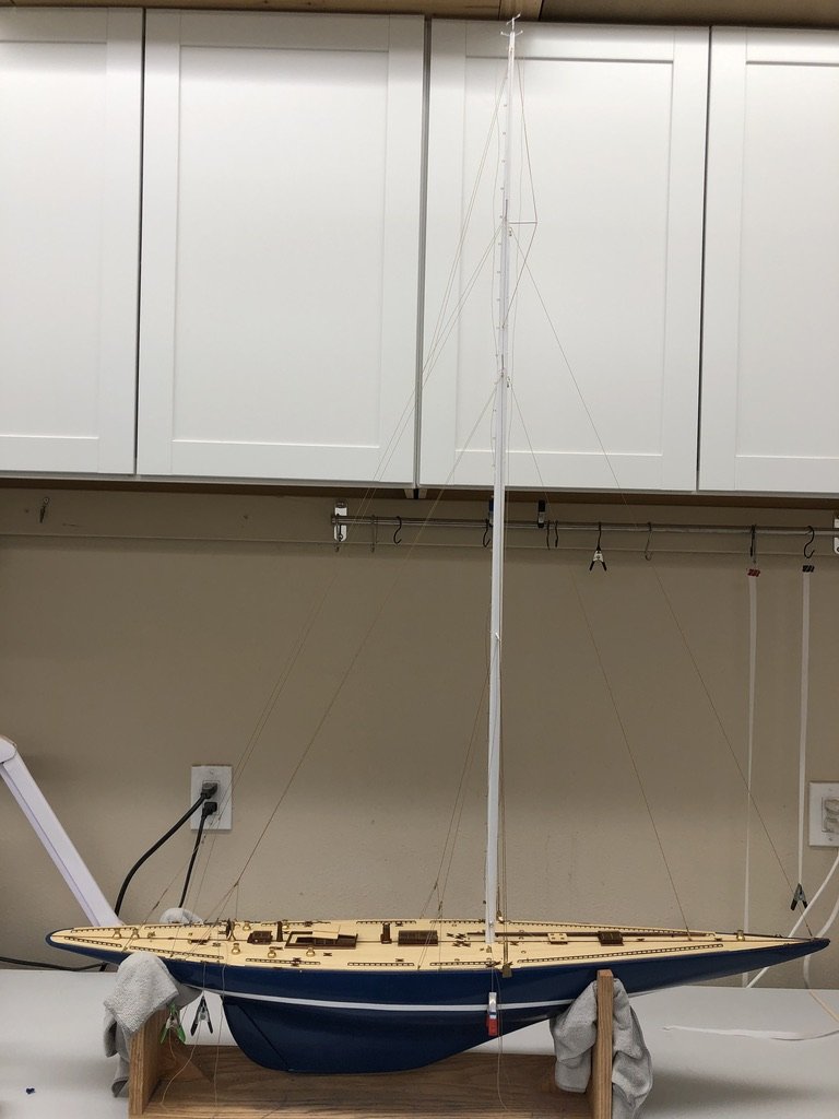
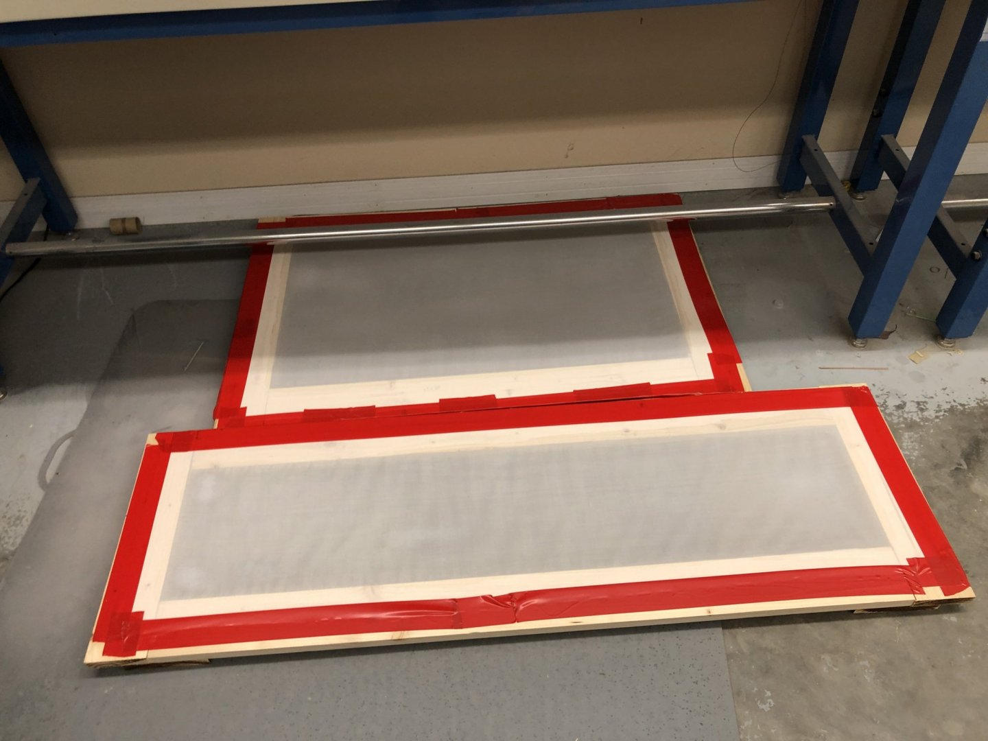
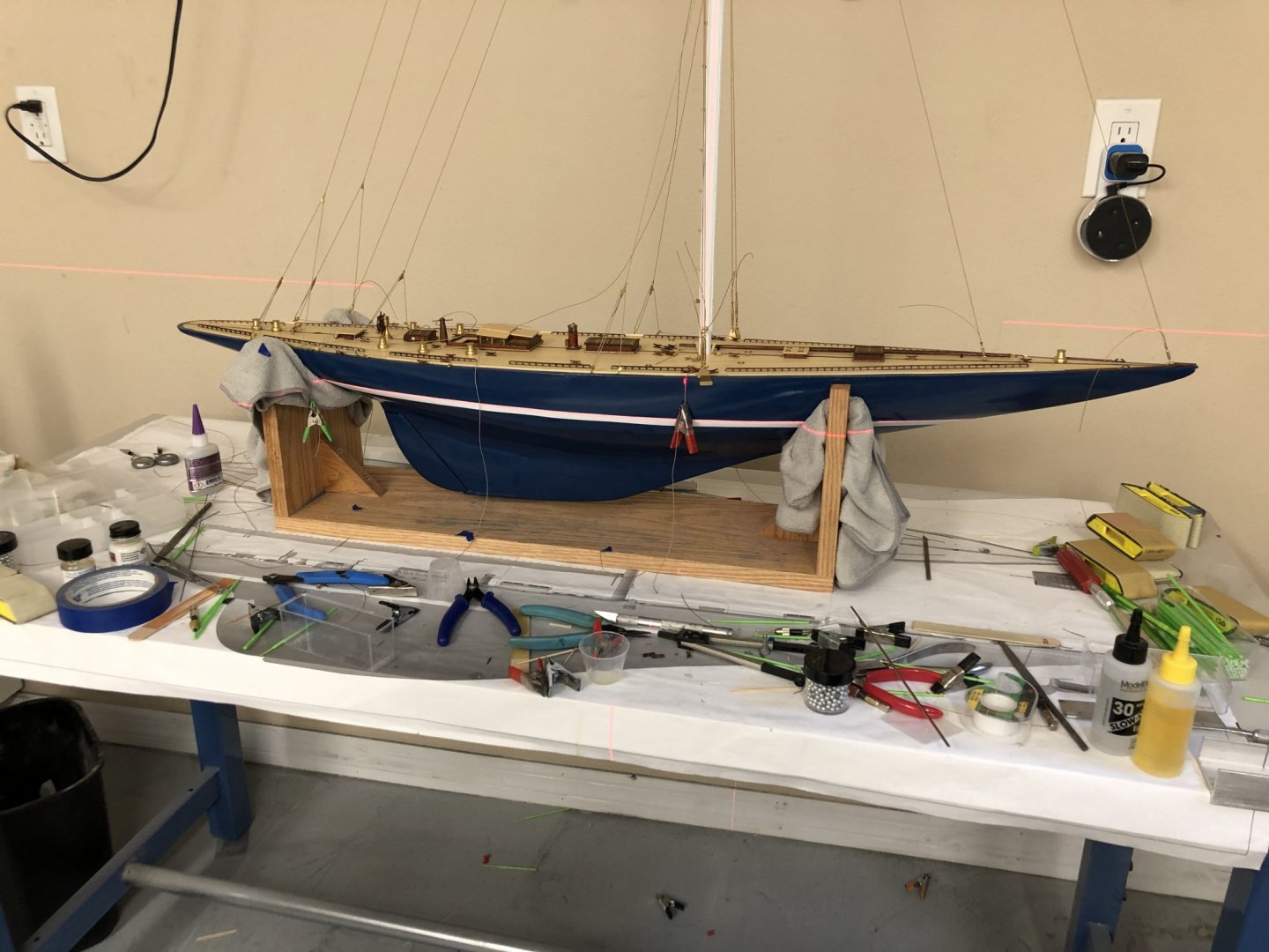
Here is the redone main sail template laid on the fabric still in the frame. I got lucky. I made the frames based on the erroneous dimensions taken from the enlarged sail plan but I added enough "fudge" that the required dimensions fit, just. I decided to use metal wire (Beadalon silver) for the main halyard with .018 Syren tan "grafted" on the end to go around the winch I added on the mast. Hopefully my "graft" is strong enough to hold, but there should not be a great deal of tension as the mail sail is attached to the mast at 31 eyebolts. I ordered 1.5mm eyelets and (hopefully) the tool to set them from Amazon - due here tomorrow in theory. The sewing machine will make eyelets also so we will see what looks best and takes the least effort. A 1.5mm (.06") hole would be about 2" at scale which seems large but is the smallest eyelet I could find and about as small as the sewing machine will do so..... I planned on putting eyelets in the mainsail opposite the eyebolts on the mast and then using "small stuff" between the eyelet and eyebolt. I have yet to figure out how to get that done amongst the back stays but it can't be worse that the running rigging on Niagara and I survived that. Similarly for the jibs, eyebolts in the sail and split rings to serve as jib "hanks". I am considering making my own jib hanks out on annealed steel wire but I have not tried that at this scale before and even when I did they just sat at the base of the fore stay, no sails on that model. And here is a shot of Endeavour with as much of the background clutter removed as I could accomplish quickly.

-
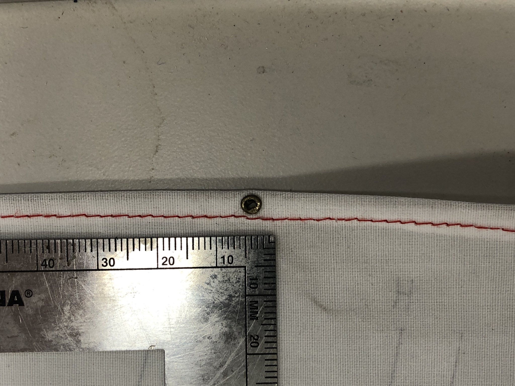
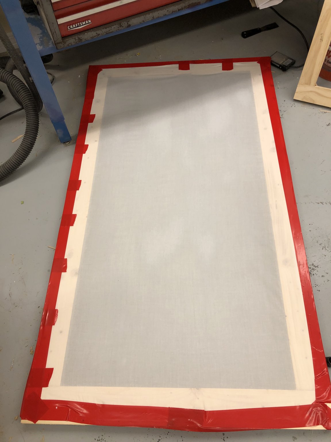
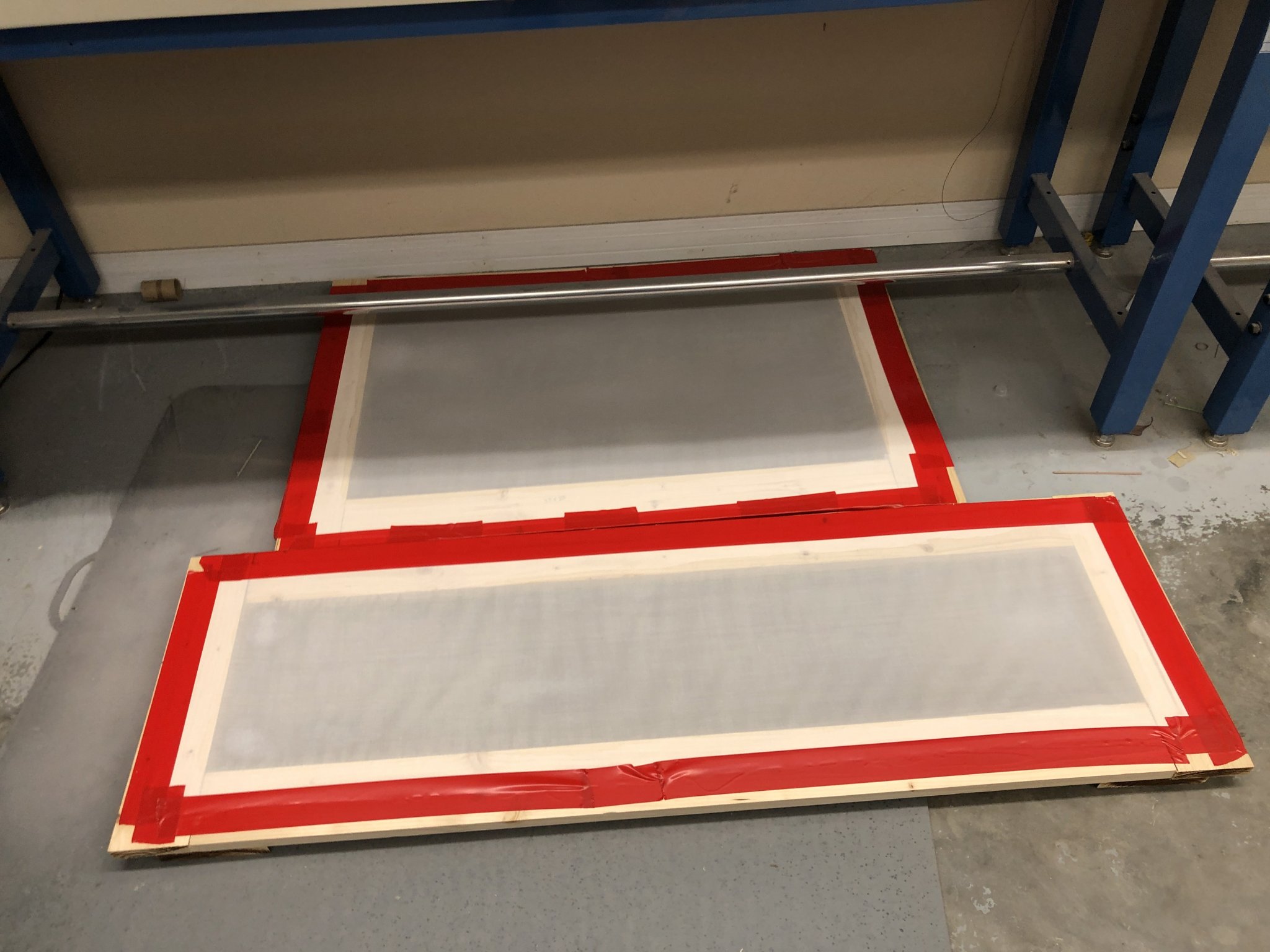
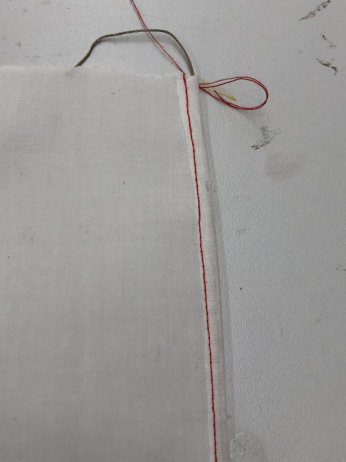
While messing around with the sail templates I also fitted the three frames I made with cloth and 50/50 white glue (Elmer's Glue-All) and water to both sides (letting the first side dry before coating the other side) of the three sail frames. I also did a small section as a "test pattern". I had to set the frames on the floor to dry as I was afraid if they were not flat they might dry with funny ripples in them. Had to be careful where I stepped and kept the dog out of the workshop. My girlfriend is a pretty handy seamstress (she has about half a dozen quilts in various stages of construction) and she wanted to she what she could do to help. So I took my test piece and a length of .025 Syren tan line that had been coated with white glue and hung to dry and got her to stitch the line into a 3/8" (more or less) seam to approximate a bolt rope for the foot and luff of the main sail. She decided to use red thread to make it easier to see where the stitches went. My next test is to use a pencil to mark the seams in the sail to see how that works. I am pretty sure she could sew them into the sails but I fear it would cause too much puckering (I have seen some pretty ugly examples of this) so I want to try the easy way out first.

-
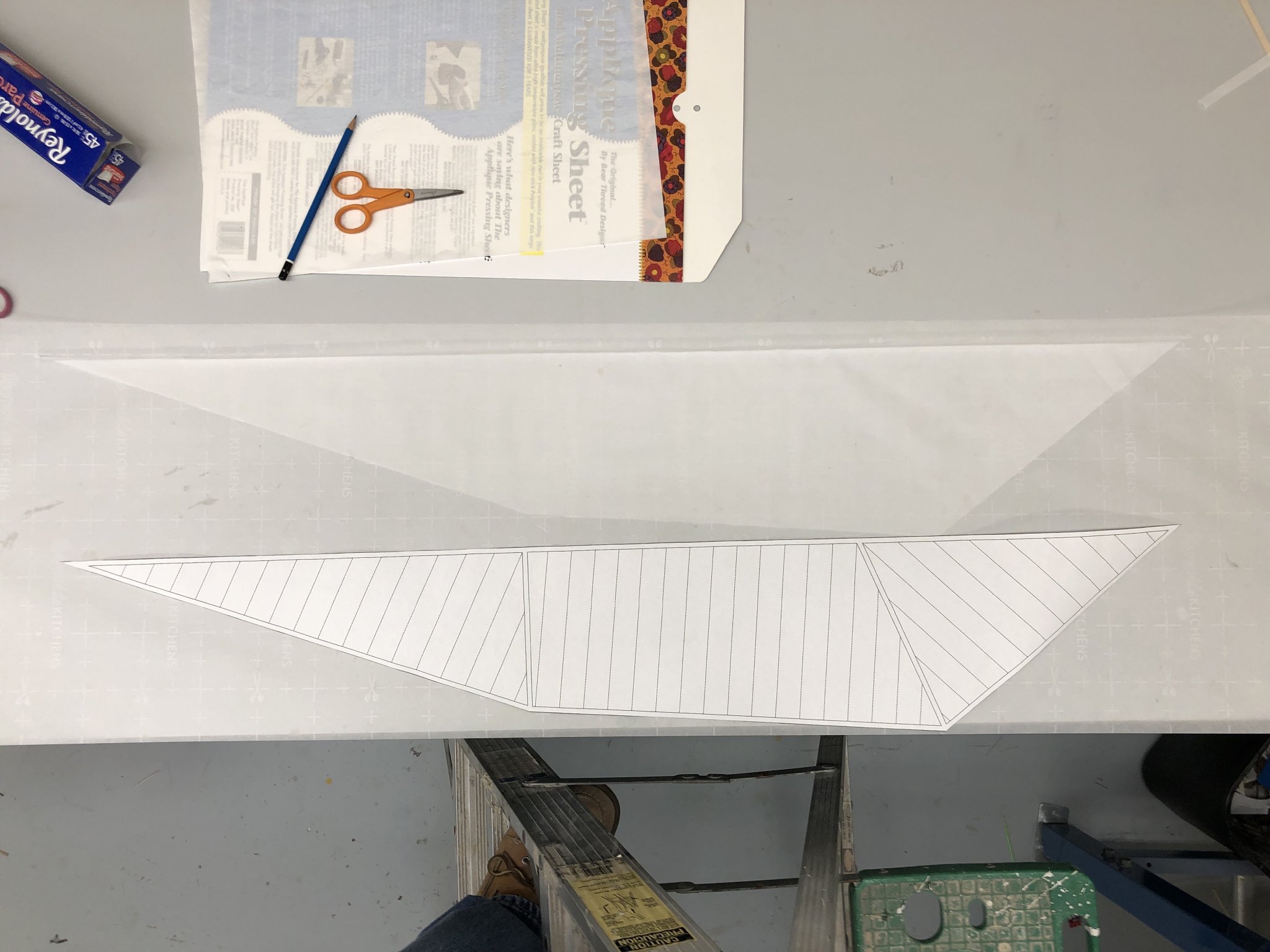
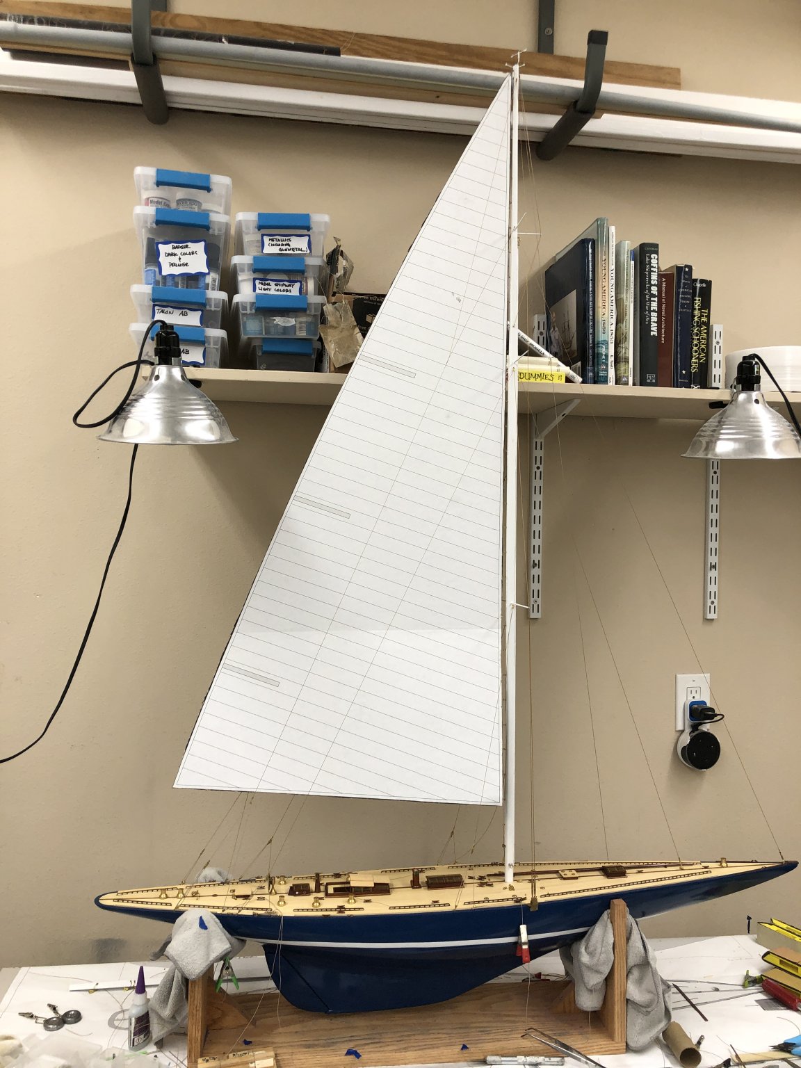
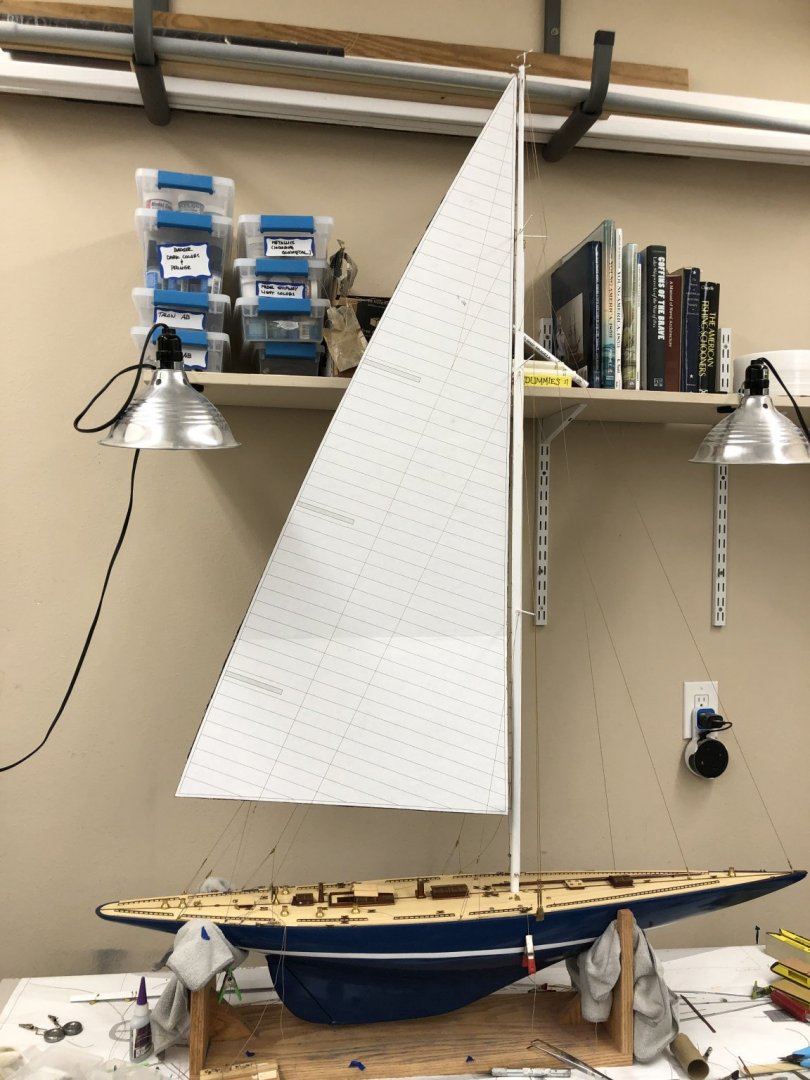
With the hull complete except for the boom I turned my attention to the sails. I had previously taken the sail plan (which is at half scale) had it scanned in and enlarged to make it full scale. I wanted to see how the sails would fit on my model since it is certainly possible that I had mis-measured or tolerances had worked against me and the sails would be too small or large if I just took the drawing as gospel. I cut the main sail out from m y "full-size" sail plan and glued it to a piece of cardboard. I fitted a shackle and halyard to the head and, being careful to route it between all the stays " ran it up to the masthead. Good thing I bothered - I guess the scaling job at Fed-Ex Office was not as accurate as you might like. As you can see in the picture below, the main sail is about 3" short of what it should be. Not surprisingly it is also about half an inch short at the foot. I am going to take Sheet 5 (that shows the sails on the boat) to Fed-Ex Office and get several full size copies made so I can get templates for the "real sails" made. It will be easy to verify that the copies are the correct size - just lay them on top of the original.
-
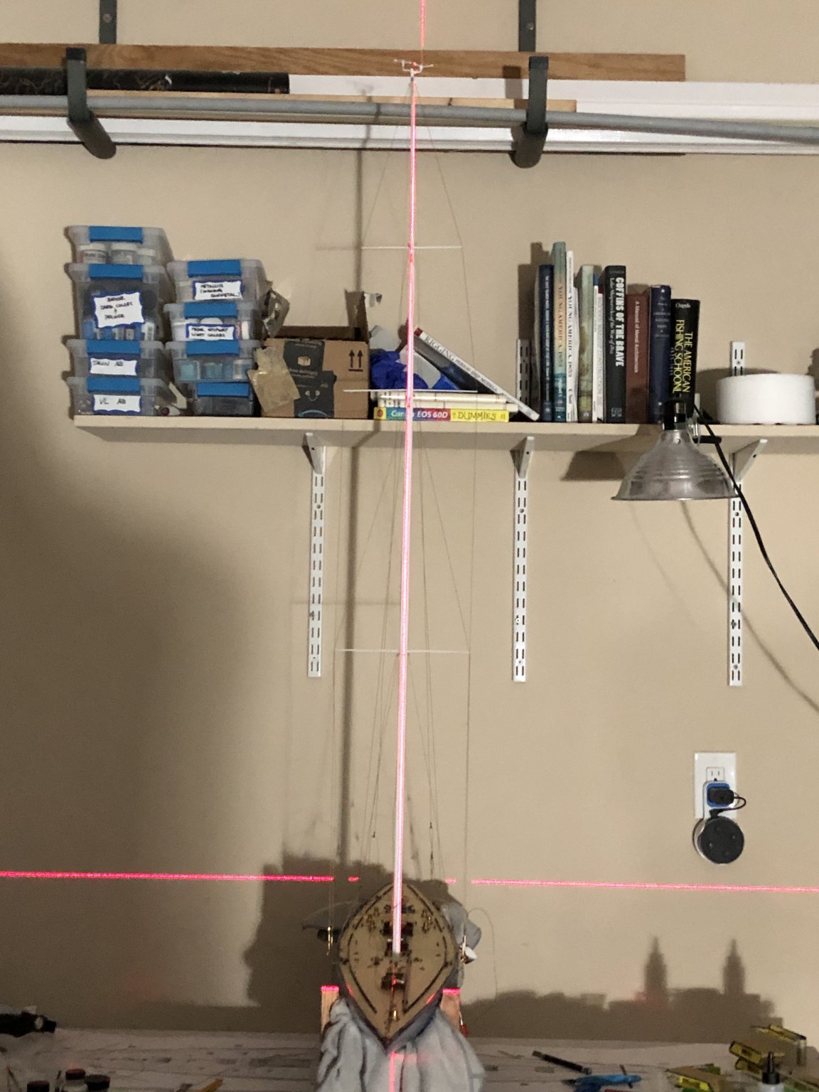
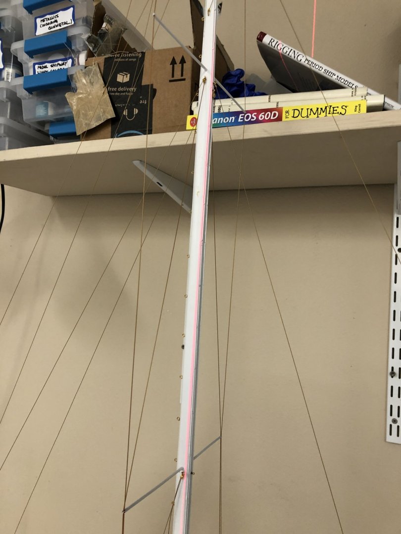
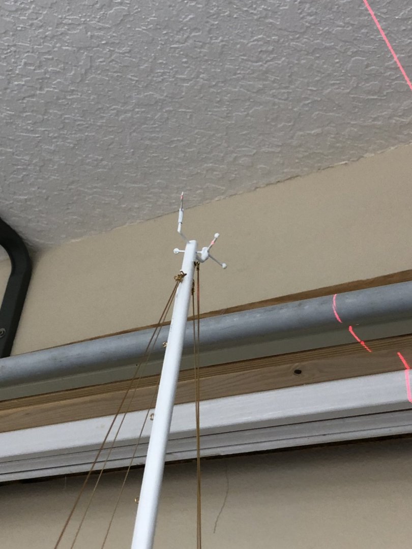
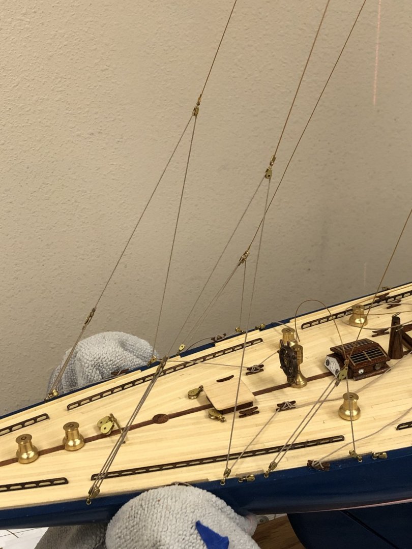
With the back stays in place I used the laser level to check the mast alignment for and aft. I adjusted the model in the cradle to get the laser and water line matched up as hopefully this means that the hull in "level" at least locally. Then I moved the cradle around on the workbench to get the vertical line in the center of the mast at deck level. Then I checked where the laser falls on the mast as it goes up. The laser line is off the mast forward just above the second spreader and at the top looks to be about 8mm (aka 5/16") forward of the mast. This equates to just short of a foot at full scale (5/16 x 35 = 175/16 = 10.9" ~ 1 foot since I am not sure how accurate my measurement was). There is nothing in the instructions about mast rake but I would assume there was probably some. Looking at the full scale sail plan and assuming that the hull is shown "level" (the entire hull length is not shown on this drawing but the deck clearly rises toward the forward end so...) and that the borders are perpendicular to the hull waterline shows about 1 3/4" inches of rack/bend to the mast. I think I will stick with 5/16". Given the amount of clearance between the mast and the deck opening aft I do not think I can get much more rack and I do not want to stress the fore/back stays to get more bend than is there already. With the sails on her I do not think anyone will take too much notice of the mast as long as it does not bend forward.
-
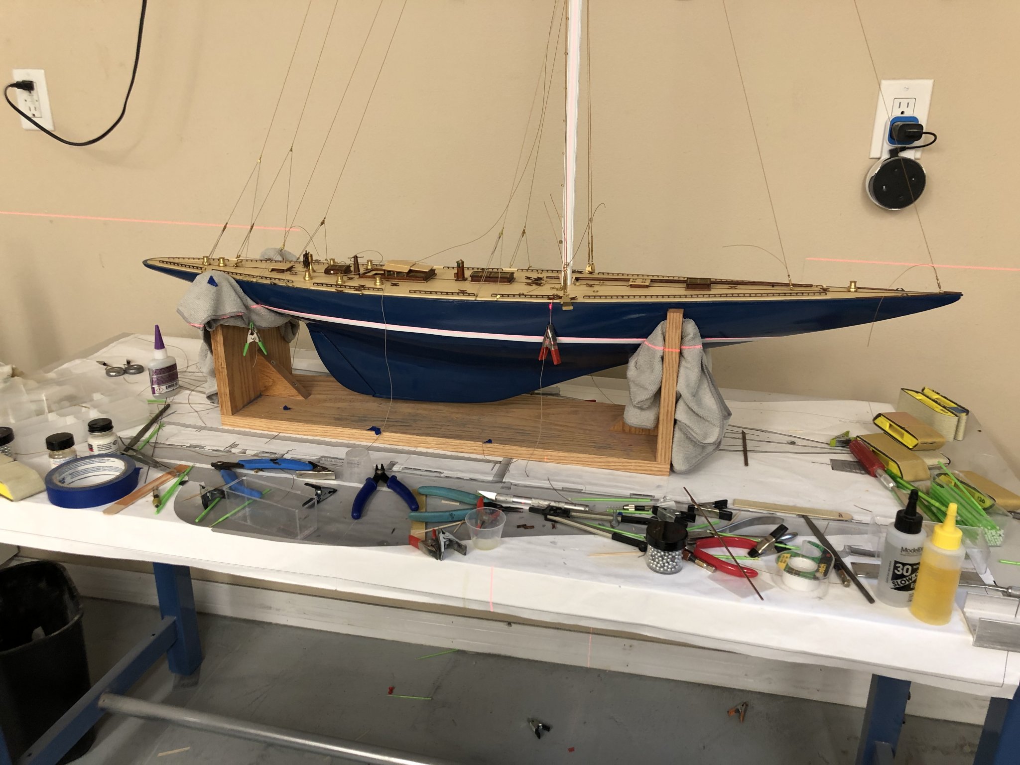
With the mast stabilized (side to side) and the new cleats installed and the epoxy set I went and rigged the three sets of back stays. I added new blocks to locations that the plans show as eyebolts to get the horizontal pull on the cleats that belay the two forward most set of back stays. I had previously replaced the single blocks on the deck with doubles at the after back stay to accomplish the same purpose. Here are the three sets of back stays as adjusted. I have not yet decided how to handle the excess line and in some cases the lines are not completely belayed (around the cleat and over the side with a weight since I will likely have to adjust some when I see the mast alignment.
-
Before replacing the cleats I decided to true up the shrouds. Used the laser level to get both the model level (side to side) and the mast straight. I used small pieces of wood to wedge the mast in position while I crimped the tubes to freeze the shrouds to the turnbuckles. Then I carefully removed the wood wedges and adjusted the turnbuckles to keep the mast straight. it did not take much more than a turn or two of the turnbuckles to hold things steady. Hopefully doing the for/aft adjustments will not throw this off.

-
Keith - when retired and with a cooperative headquarters you can move pretty quickly. I am hearing noises about starting Christmas decorations so I am seizing every opportunity before that evolution begins in earnest.