HOLIDAY DONATION DRIVE - SUPPORT MSW - DO YOUR PART TO KEEP THIS GREAT FORUM GOING! (Only 75 donations so far out of 49,000 members - C'mon guys!)
×


cdrusn89
-
Posts
1,915 -
Joined
-
Last visited
Content Type
Profiles
Forums
Gallery
Events
Everything posted by cdrusn89
-
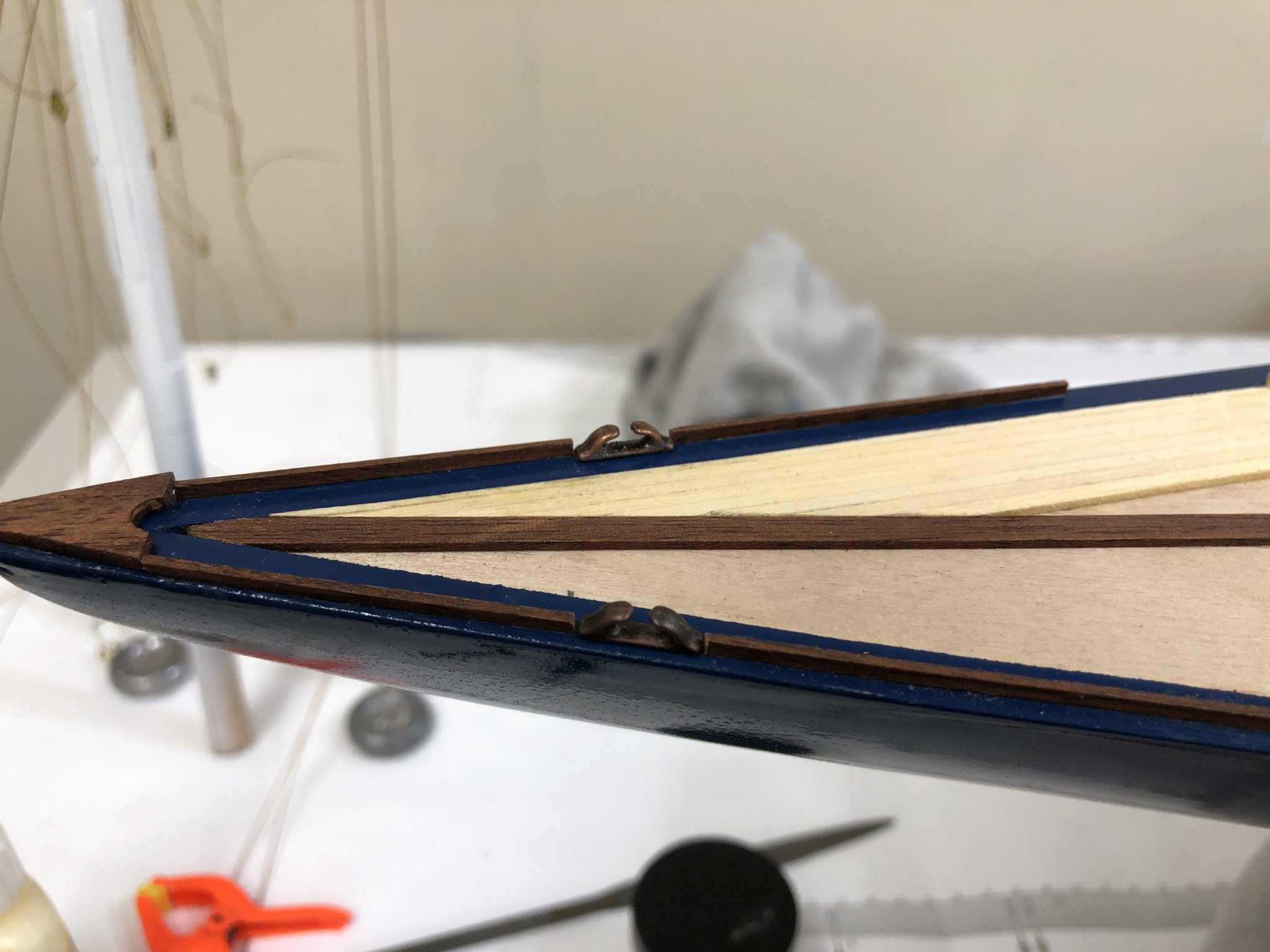
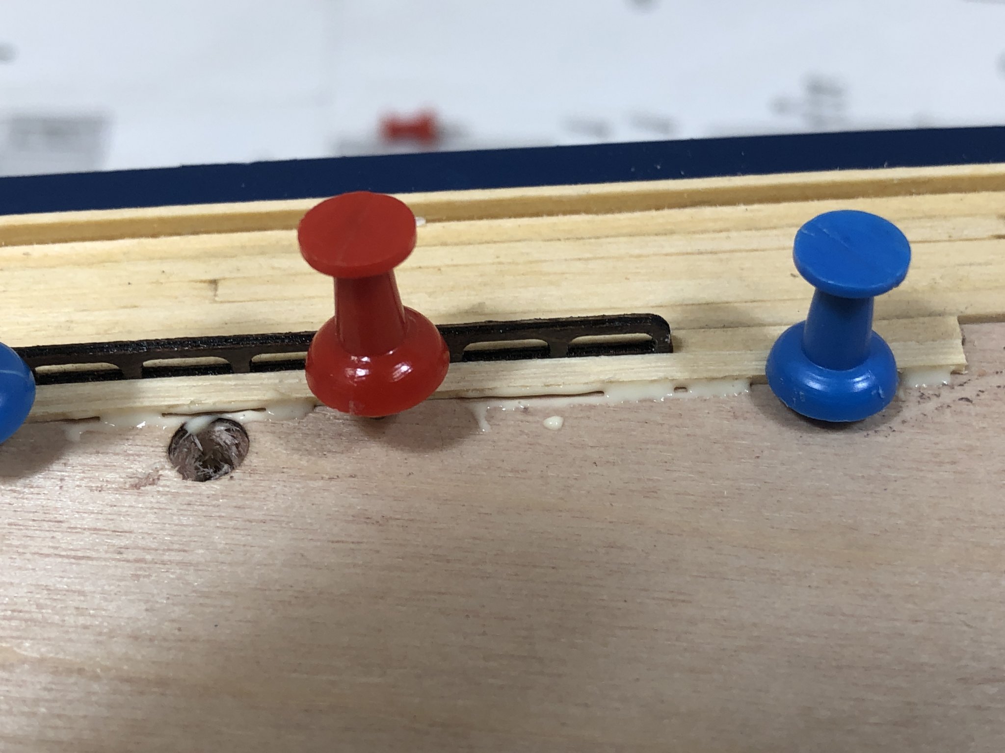
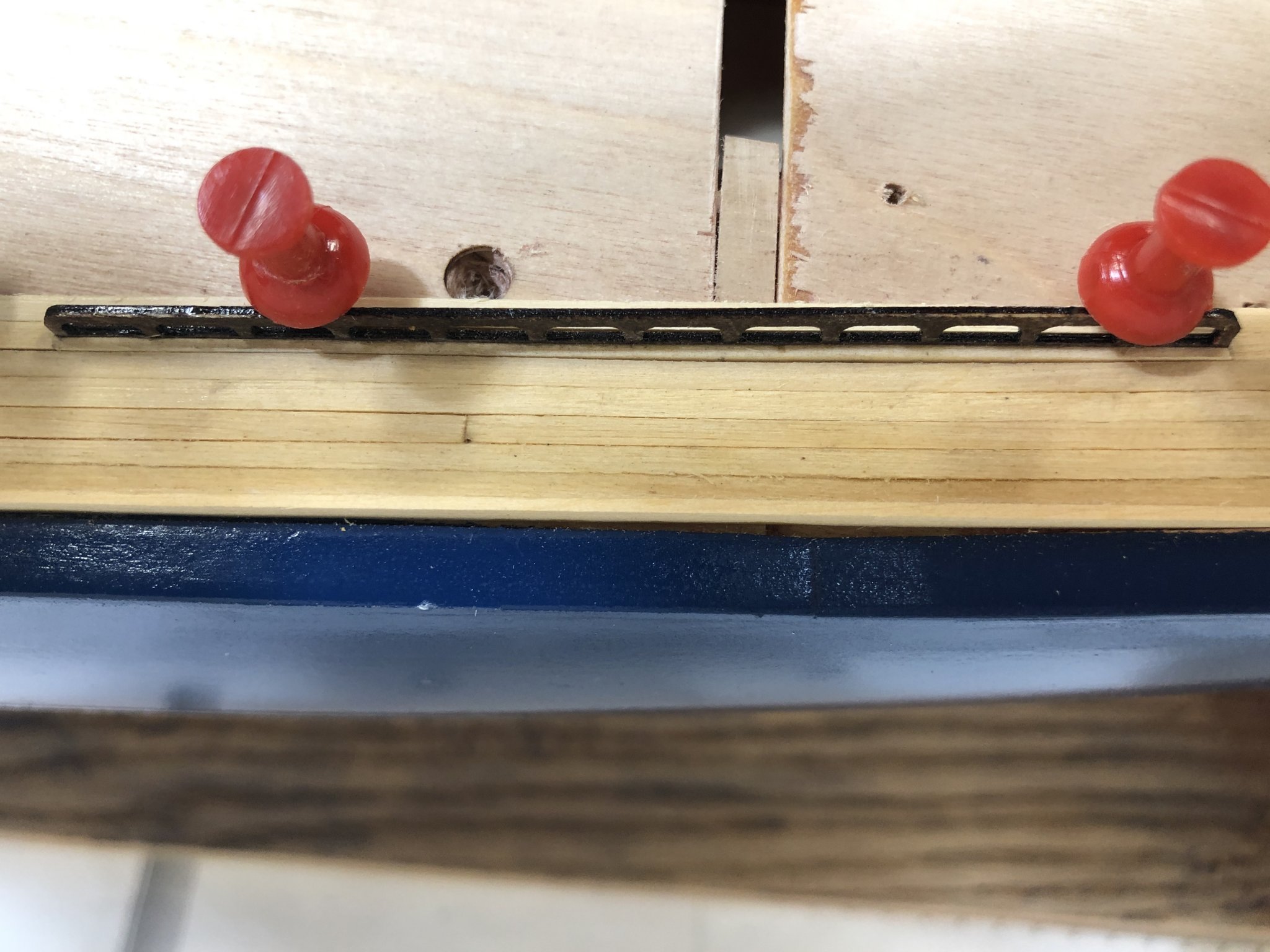
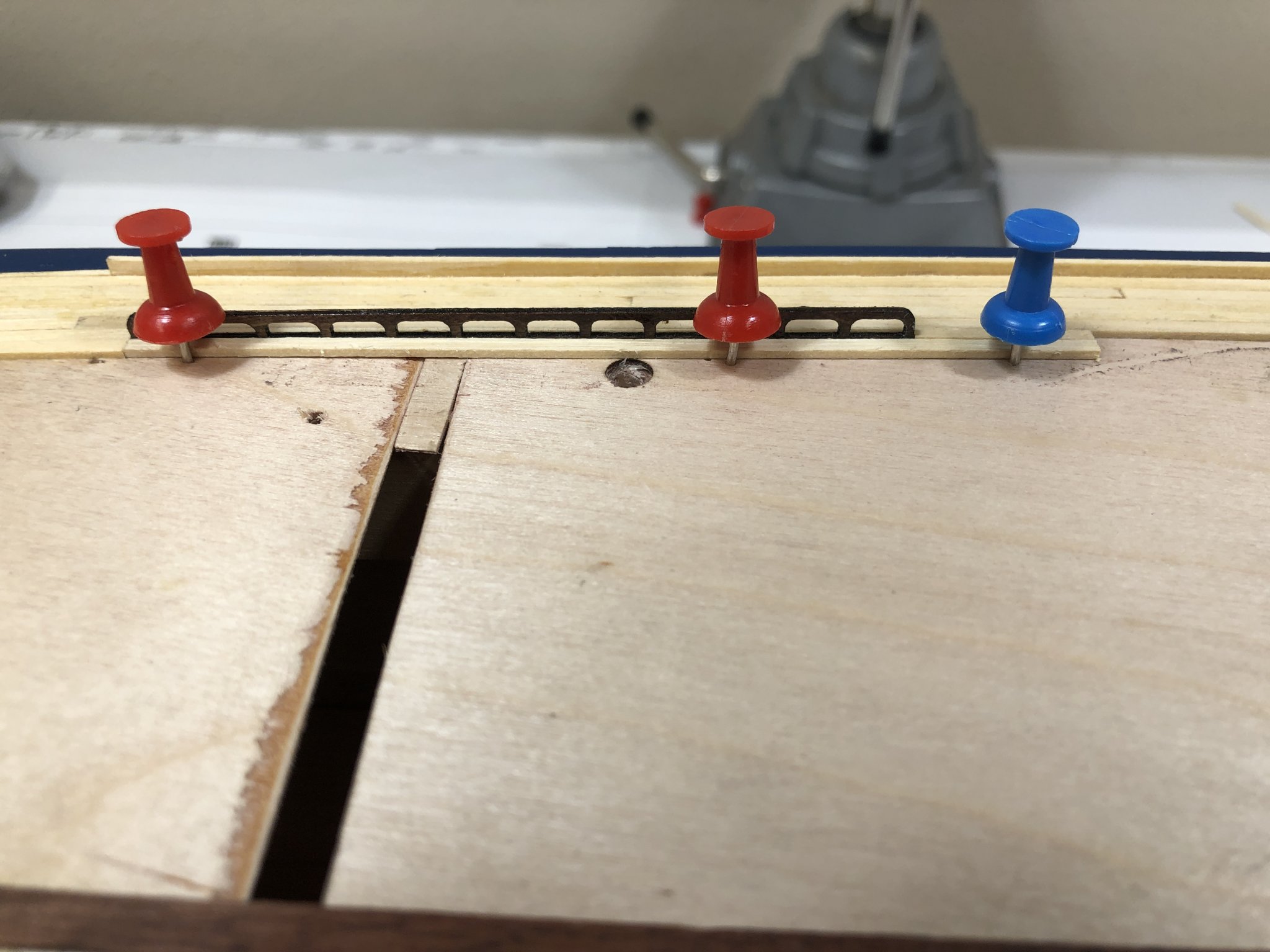
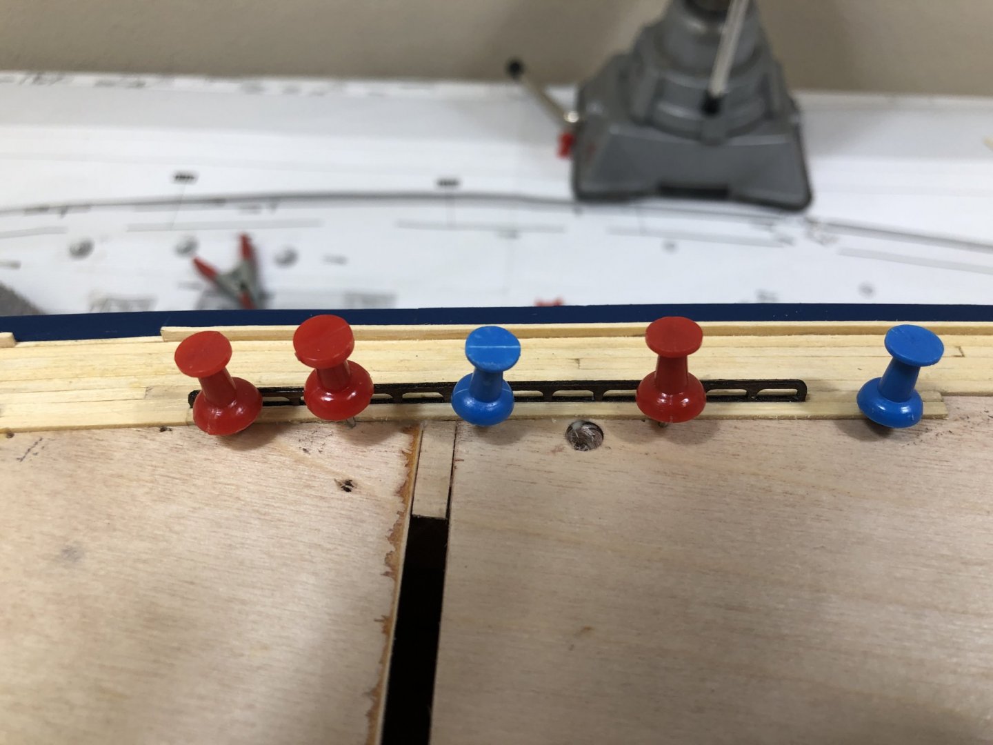
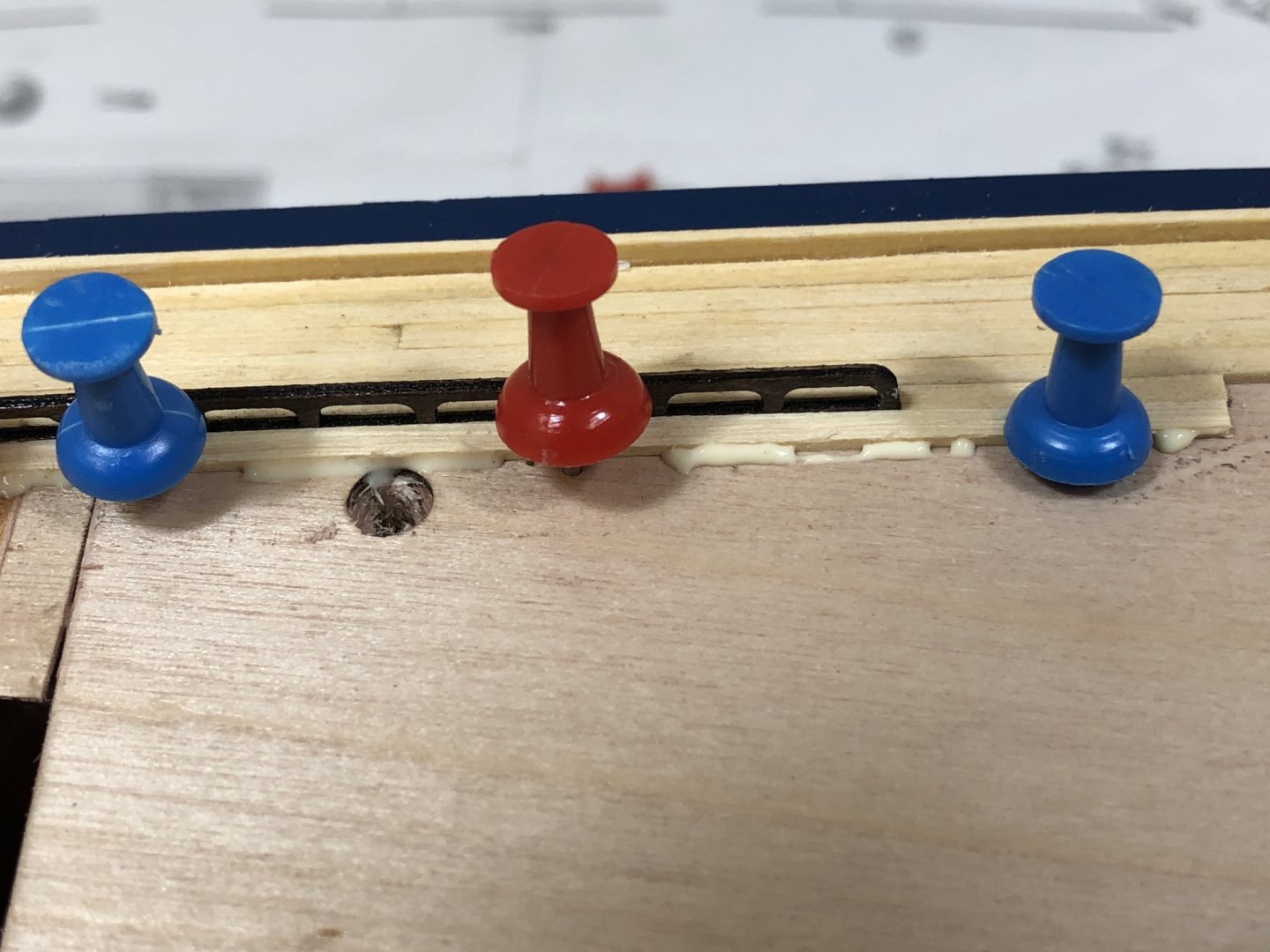
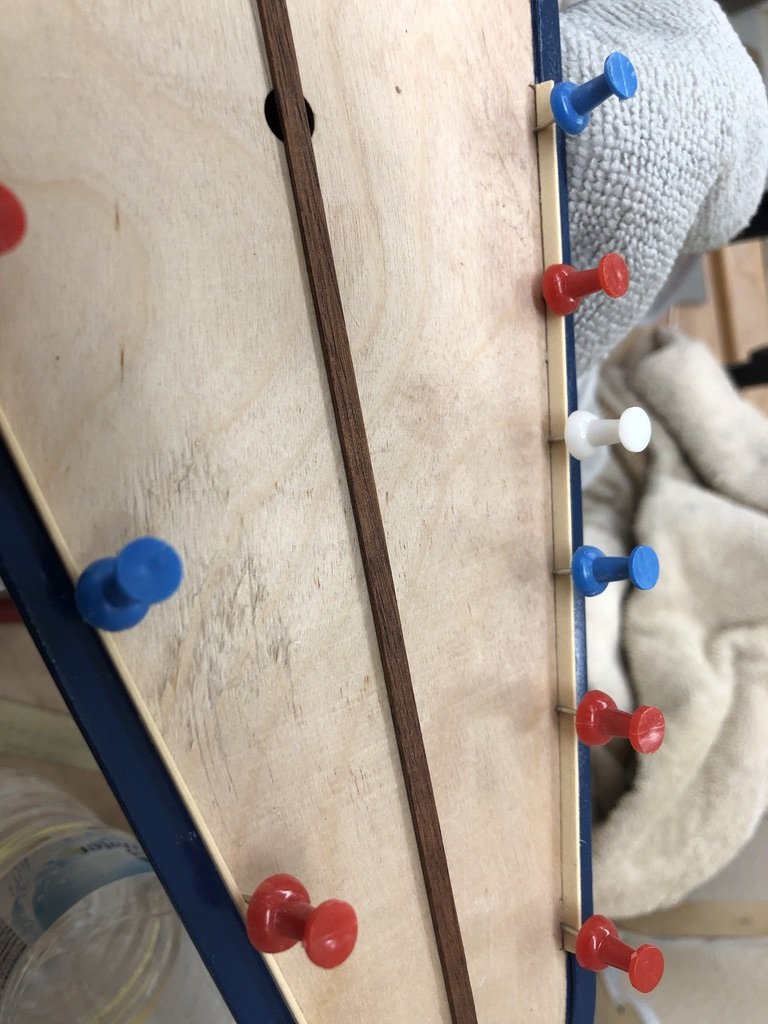
 Continuing to plank the deck and add the details at bow. Bow details were not really an issue except I had to build a new front piece. The one is the kit is too small. Not sure if I somehow got the extreme front of the bow too big or this is just another of life's mysteries. Anyway, I had extra Mahogany (which I still had to stain to get is as dark as that supplied in the kit) and fabing it was no big deal. I did have to file the bottom of the cleats flat as the mold mark puts a pretty serious ridge down the center that interferes with it sitting flat. The deck planking does present some challenges. Specifically the handrails which are supplied as laser cut pieces, six on each side. The objective is to leave an opening in the planking for these 1mm wide handrails to be installed after the planking has been completed and sanded. Sanding would be a significant challenge with the hand rails sticking up if the were installed along with the deck planks. The problem is creating the 1mm wide filler planks that will go with the handrails to maintain the 2mm wide deck planking scheme. I did not have any difficulty creating these 1mm X 1mm planks as I have a Byrnes thickness sander which works marvelously well with accuracy of about .03mm. Creating these planks without a thickness sander would be a real challenge as two of them need to be 12" long. So I sanded down some of the deck planks to 1mm X 1mm, and glued them to the side of the handrails, after lightly sanding the bottom edge of the handrail to get a better gluing surface. Once dry I placed the handrail/filler on the deck after planking up to where the handrail is located then put another plank on the other side of the handrail/filler to hold it in place. I used push pins to hold this out plank in place. Once satisfied that the handrail was where it needed to be I ran a bead of wood glue between the out edge of the outer plank and the deck. I used a pin to run this glue along the edge between the plank and the deck and then ran a damp rag over the area to pull up the excess glue. Once the glue has set I remove the handrail and move on to the next one. Order of photos issue again - the last one below shows the initial set up. The next to last one is the same shot from the other side and you can see there is a gap between the planks. In the first one of this series you see I added two more pins to close the gap before adding the glue and trying to get it in the groove.


-
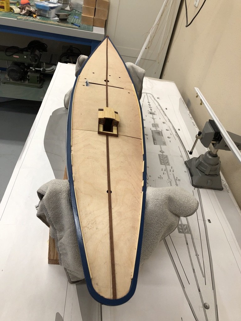
Working on the centerline Mahogany "stripe" and the deck edge pieces. I decided to keep the deck edge pieces the same as the deck (instead of Mahogany). I thought there would make the deck edge to "busy" with dark blue, Mahogany and the yellow cedar in close proximity. I dismantled my "paint booth" and moved the model over to that bench with the full size plans underneath so I can easily pick off the dimensions for the deck edge pieces. I inserted the cockpit to see where the centerline piece has to end since I believe the decking comes up to the cockpit rather than the cockpit sitting on top of the decking at the ends. I am still thinking about how to treat the deck planking edges. I assume there is some kind of caulking between the deck planks but wonder that they were still using pitch/tar in the 1930s. The darker (and very poor quality) deck planking supplied in the kit makes figuring out what was done on the model displayed on the box difficult. At the moment I am inclined to do nothing on the edges but I am still considering my options as I am not quite to the point of laying planking just yet.
-
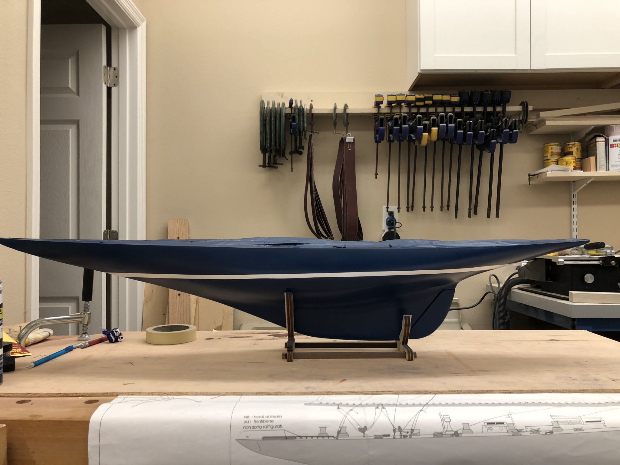
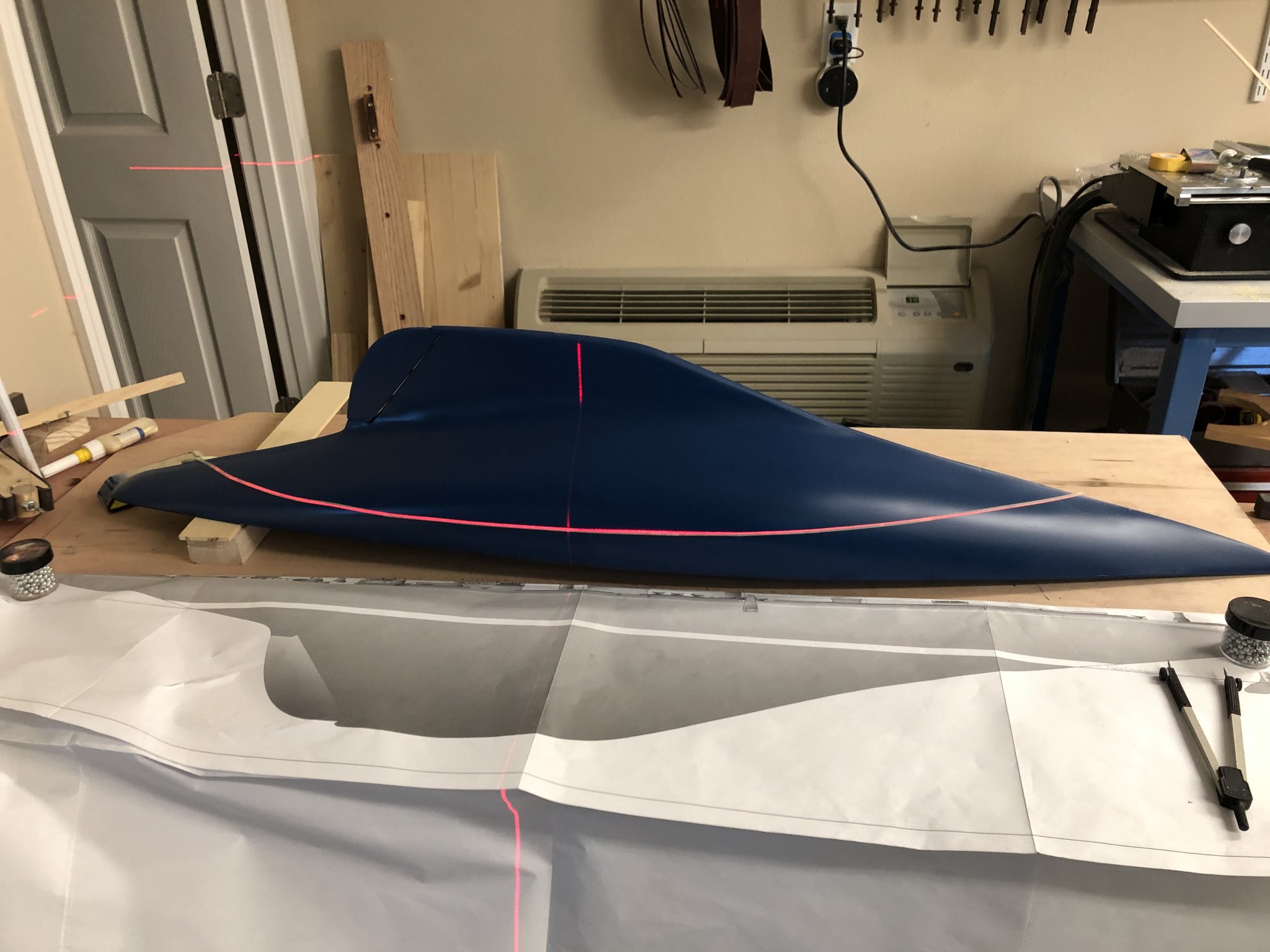
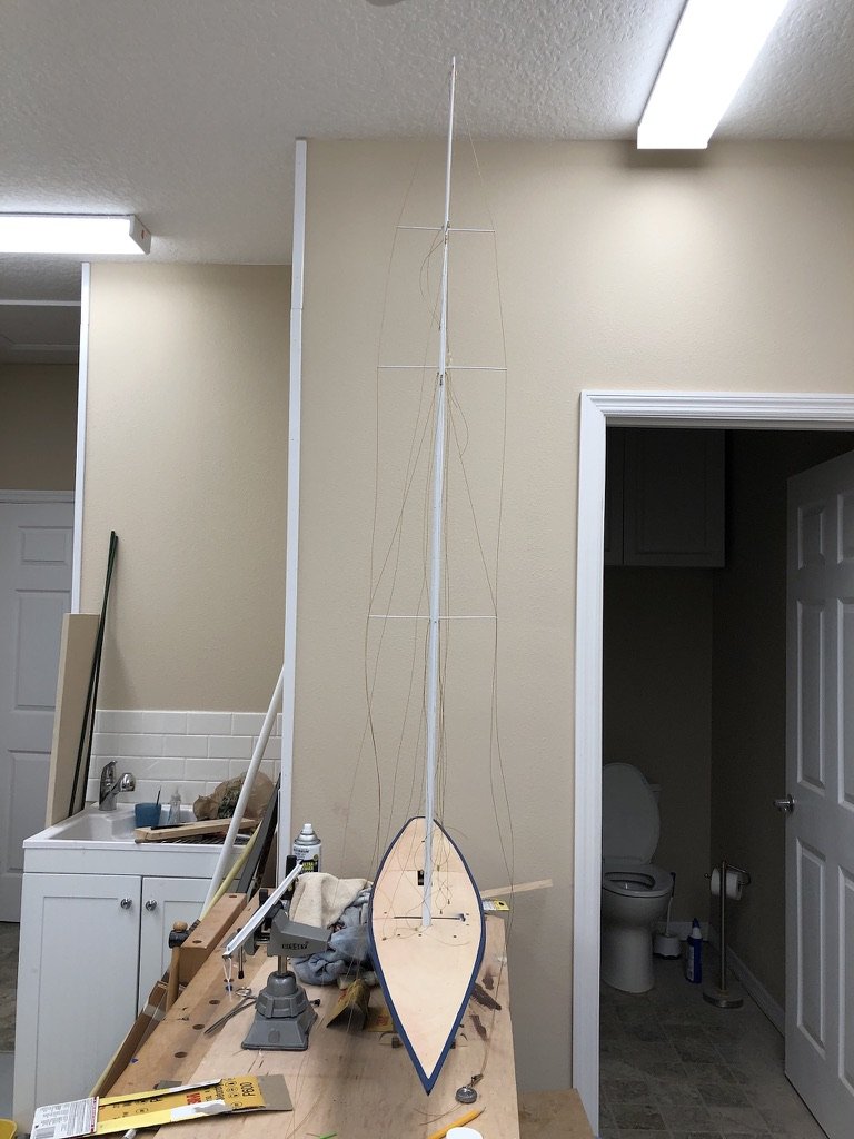
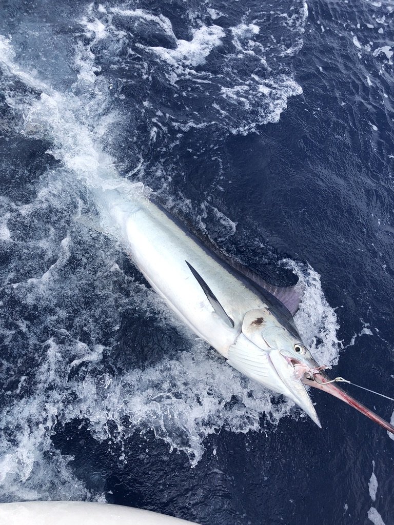
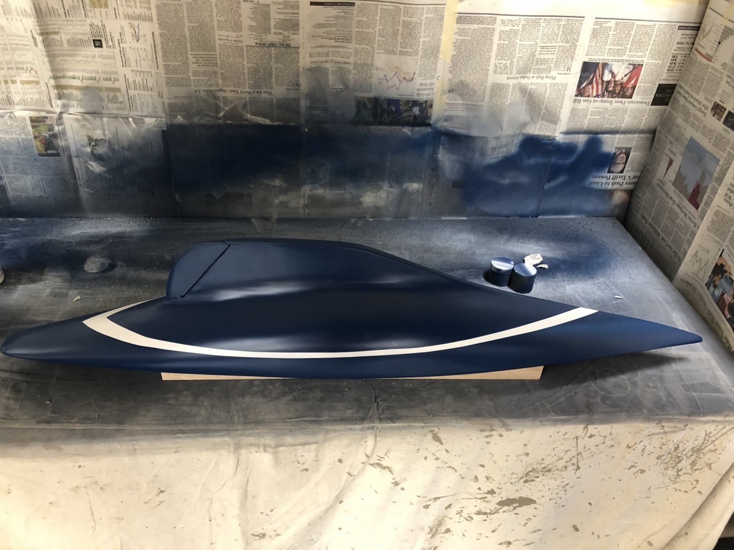
Back from Australia where I accomplished my mission to catch (and release) a Black Marlin to complete my catch of the Marlin Family (Black, Blue and White). It was a small one (by Black Marlin standards where the females can range mover 1500 lbs), probably less than 300 lbs. But a catch is a catch as they say. Anyway back to Endeavour - The hull painting is complete (except for a little touch-up here and there) so I took the masking off the deck and could not resist putting the mast up to see what it will look like. I also marked the mast so I will know how much needs to come off so the transition from round to oval will occur that the deck. I am messing around with the piece of Mahogany that goes down the center. I am going to stain it to match the cabin and have it finished gloss as well. Toying with the idea of doing the same with the "edge boards" (1 X 3mm mounted vertically at most places just inboard of the deck edge pieces. As I read the instructions (and from the pieces of wood provided) it appears that these should b e the same material as the deck - which in my case is yellow cedar. I may make up a few pieces of 1X3mm Mahogany just to see how it looks. So here is the Black Marlin and the hull with the mast installed.
-
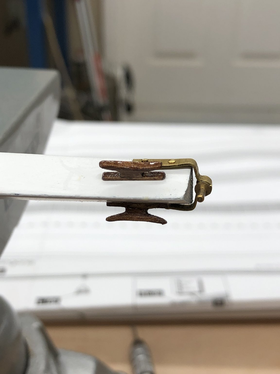
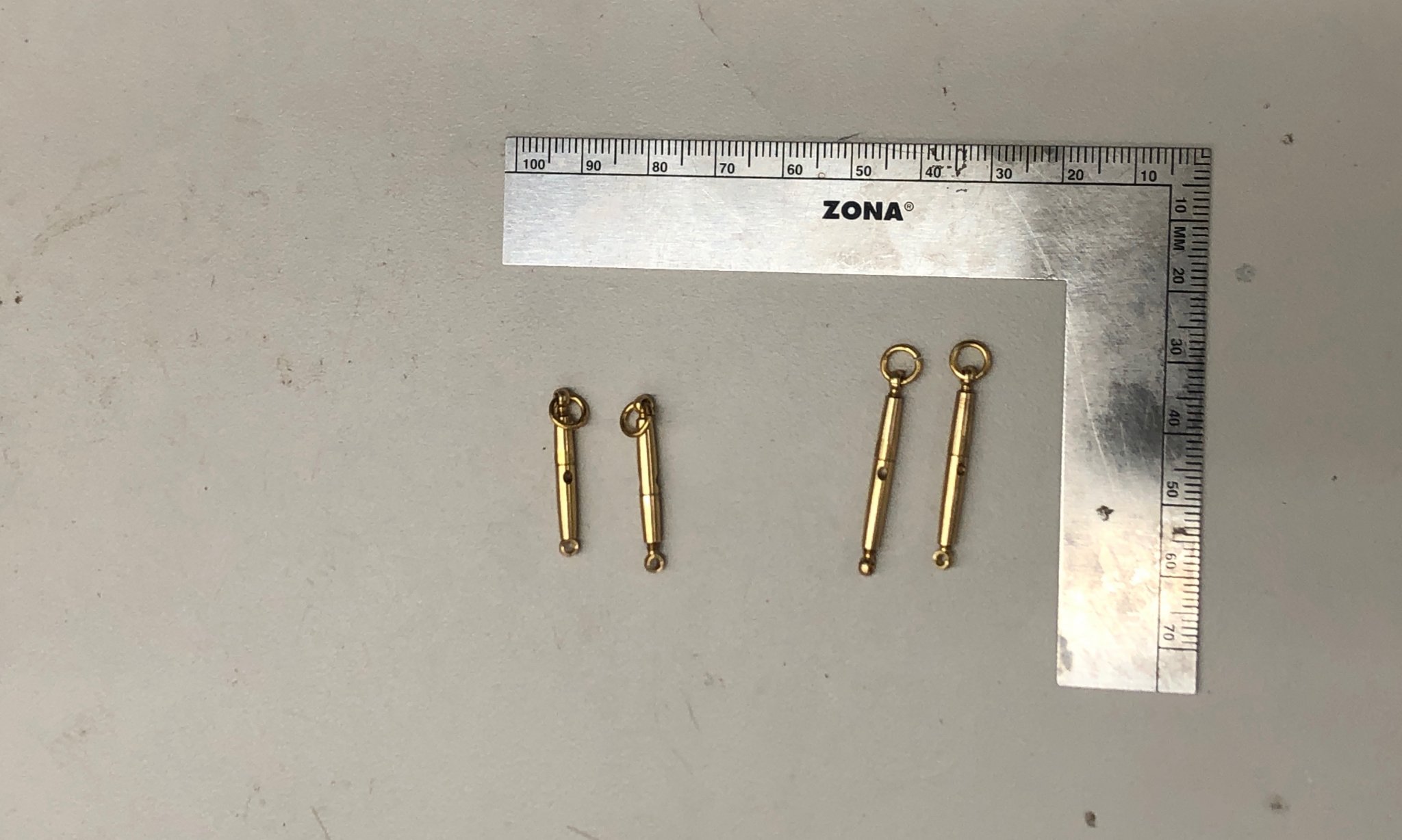
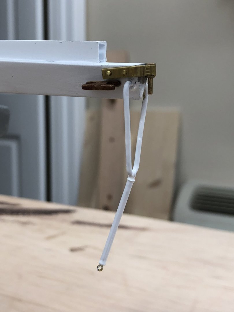
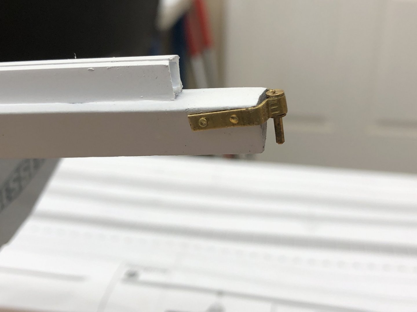
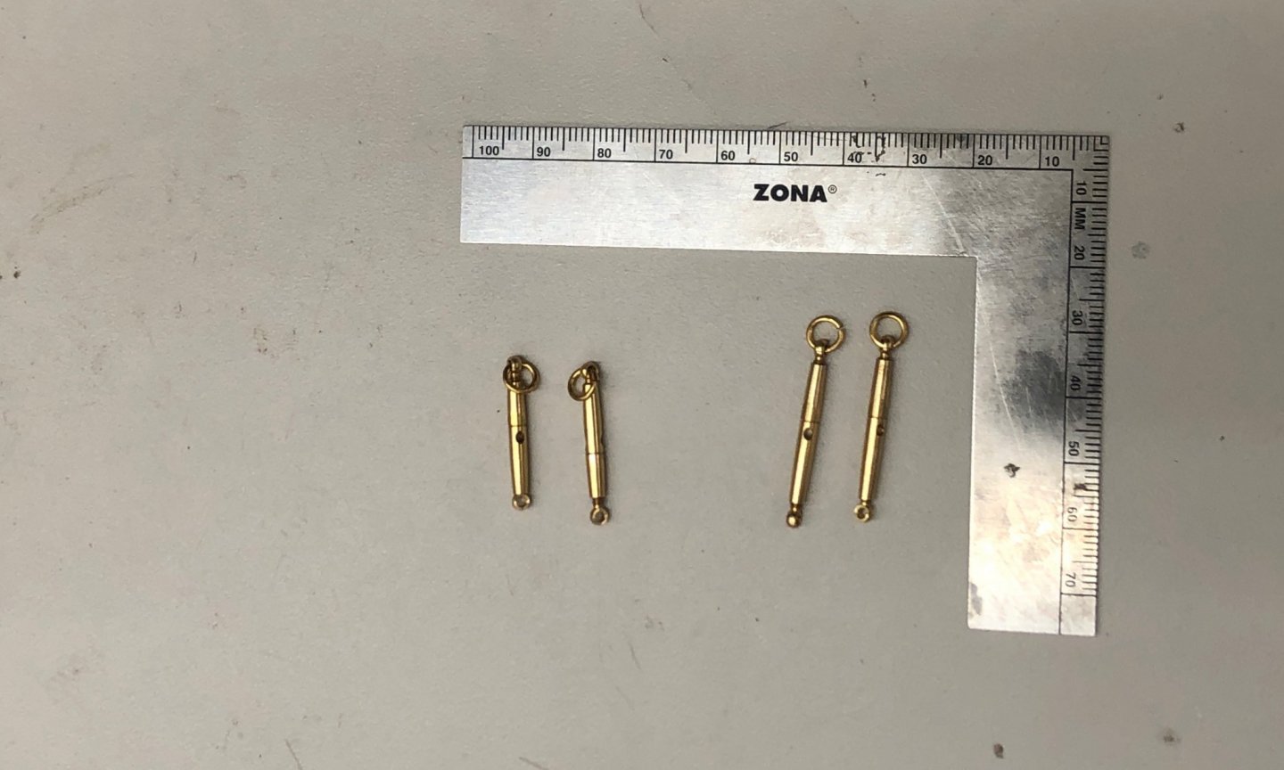
Cleaning up some odds and ends while waiting to put the gloss on the hull (and go fishing in Australia). I decided to paint the boom vang (I assume that is what this would be called today) white like the rest of the boom. I tried three times to get the "V" shaped piece to be completely symmetrical but it the end decided that "close" was good enough. I used 1/8" brass rod and 5/64" copper tubing (from the kit) and the kit supplied eye bolts. You really do not notice that one side has a sharper bend at the top than the other unless you look at it straight on without the mast in the way - which will be impossible once everything is assembled. I also tapered the provided dowel for what I assume is a "whisker pole" since there is no mention of it in the instructions (written or graphic - it is shown on the topside placement drawing but not elsewhere). I stained it to match the cleats, hand rails and cabin sides. Gloss acrylic to follow when the stain is dry and eye bolts in both ends.
-
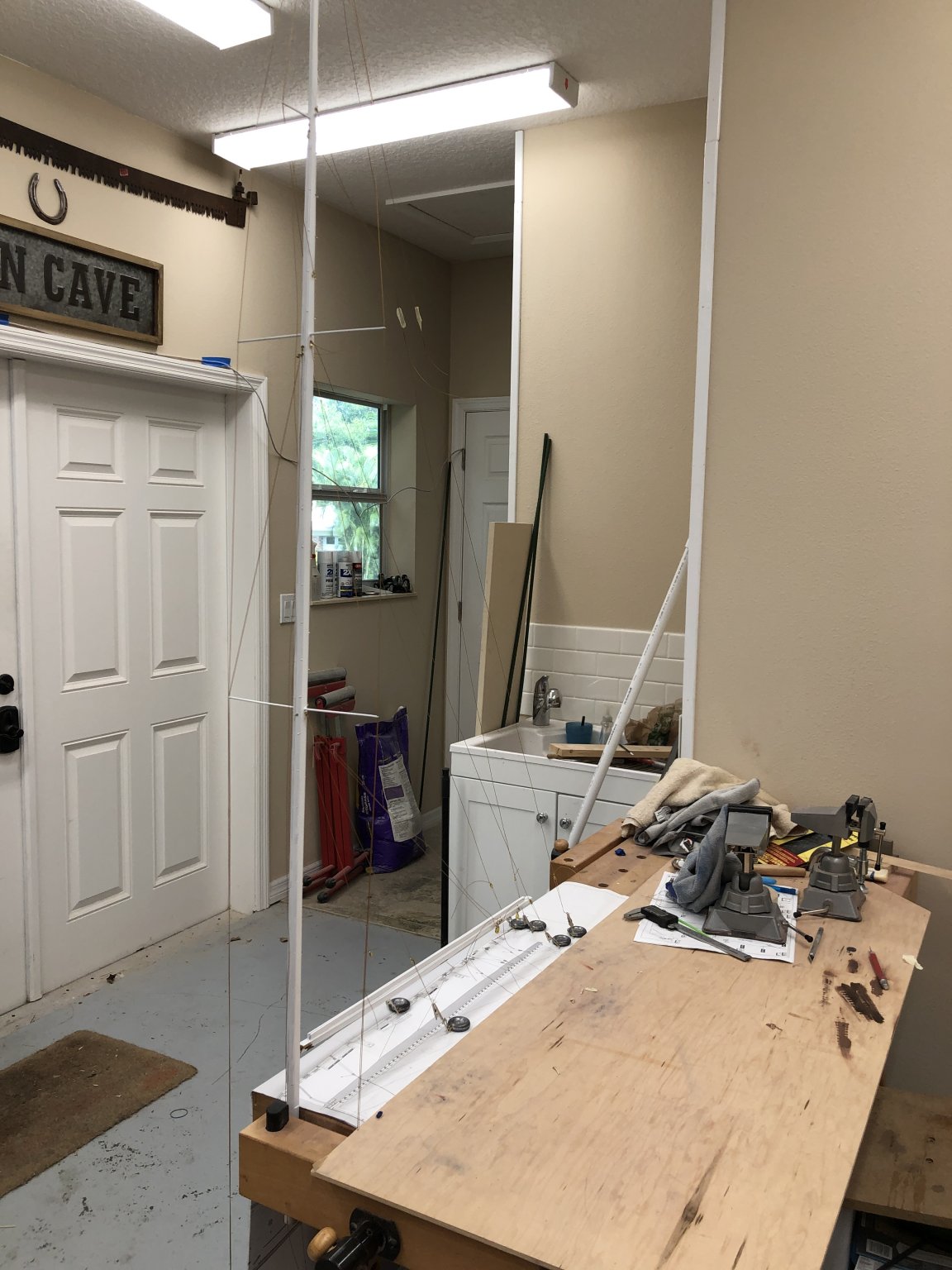
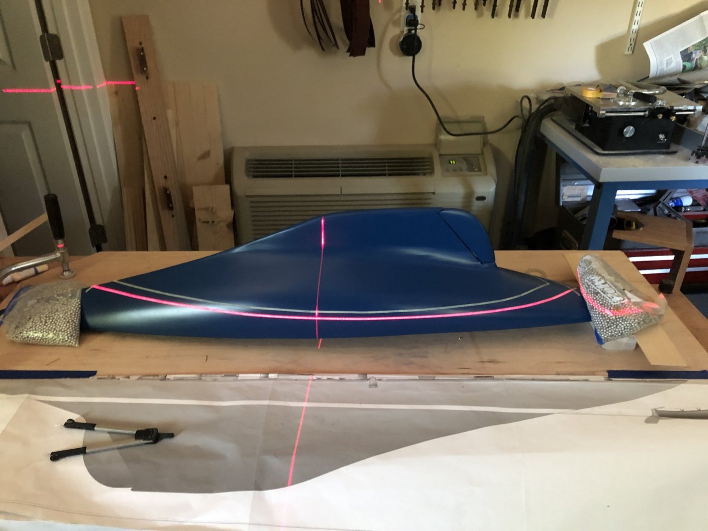
Keith, I originally got the laser to get the lines straight when I put tile down in the storage room next to my workshop (the builder did a pretty terrible job getting the walls to meet at 90 degrees). I used it to ensure the masts on my Niagara were correctly aligned athwart ship but had not tried it with the waterline until now. I doubt I will use any other method going forward. For what it is worth I am using a Bosch GL 50 (Made in China, of course) which has the "auto-level" feature to "ensure" the line is truly horizontal (in some sense that mathematicians can argue about endlessly).
-
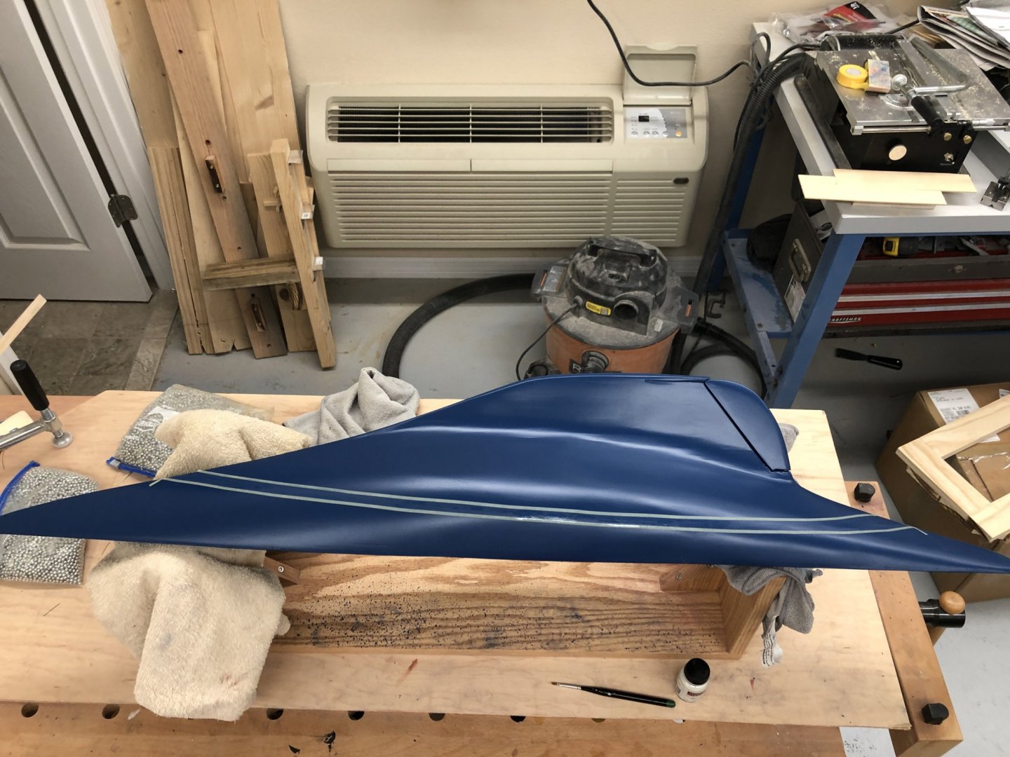
I decided to get the rail painted with gloss now, so I can get the bottom tomorrow. Here is the hull after the top (rail) was painted. Will put the gloss on the rest of the hull tomorrow (48 hours after the white was applied).
-
Tom, I too am lathe-less so rather than use the kit dowels (mine had significant warps/bends) I started with square stock. I tapered the square stock to get close to the desired dimension (taking into account that the square cross-section has to be bigger than the desired round diameter - I actually passed high school geometry) then using a jig to hold the square stock with the edge up I used sanding sticks (actually tongue depressors with sand paper glued on) to make it eight sided then further sanding to get it round where required. It was easier than I expected and it was much easier (for me) to taper the square section wood evenly and it gets the eight sided areas in the process. Trying to make something eight sided from round sounds difficult (to me).
-
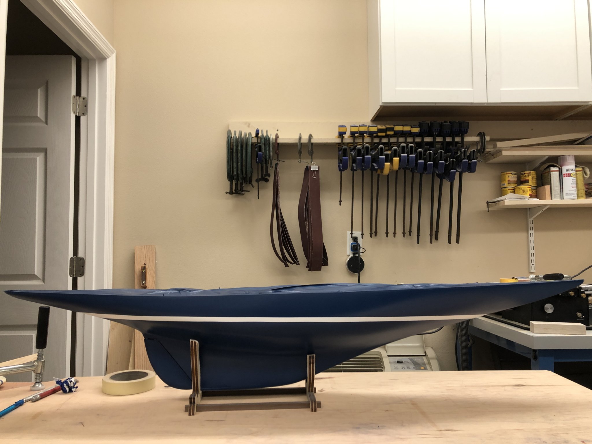
Thanks Yves - I apparently dodged a bullet this time. The paint came off in flakes from the tape but stayed intact on the hull. Here is the hull in the kit provided stand with the waterline stripe complete. Plan is to put the gloss coat on tomorrow morning (paint can says clear should be applied 1 hour or 48 hours after color) before heading to Australian fishing trip. Hopefully a big Black Marlin is in my future. Gloss coat should be completely dried and solid by the time I get back on the 25th. Then the deck planking can begin.


-
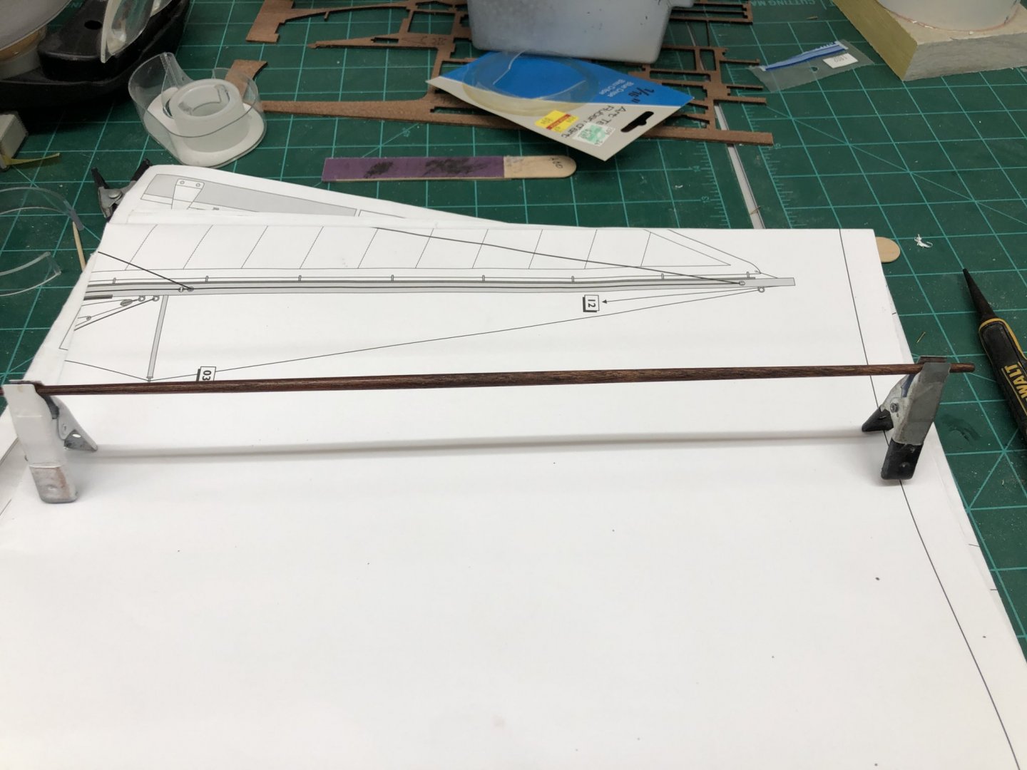
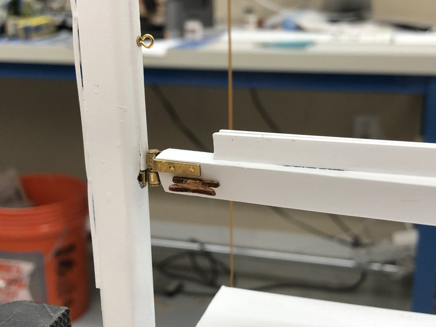
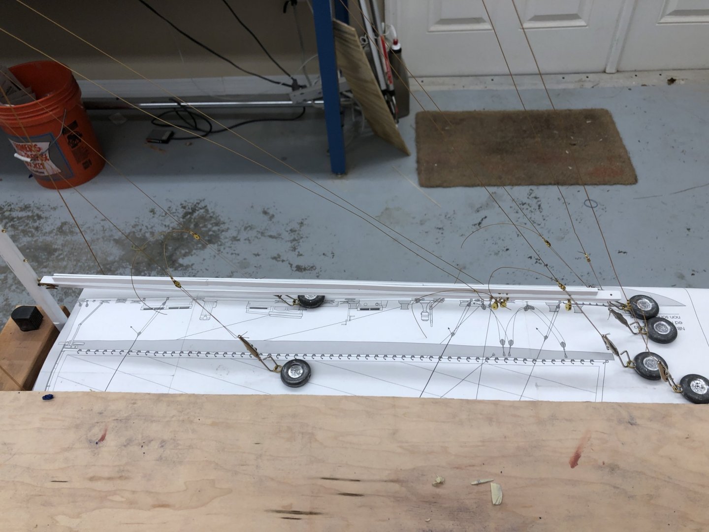
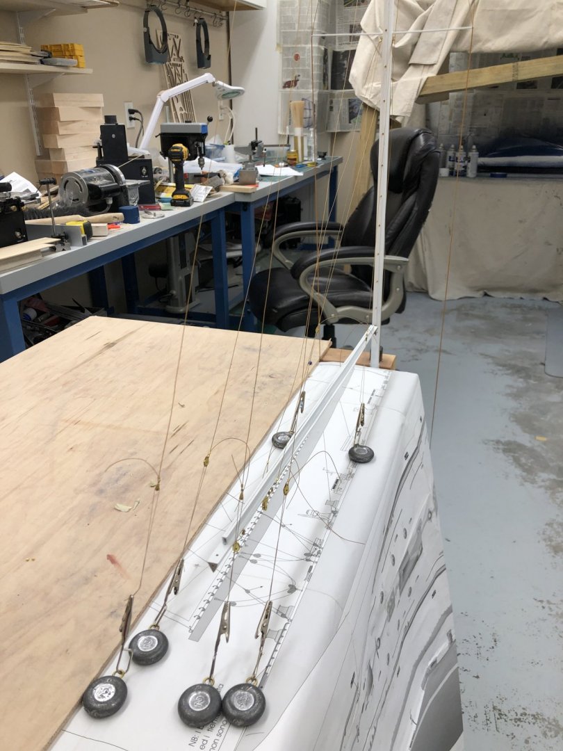
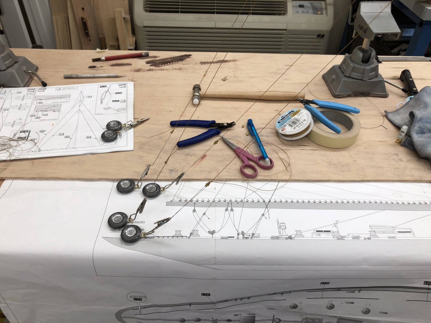
It is taking all my will power to not strip the tape off the waterline stripe now that the paint has "dried" enough to handle (according to the instructions on the can). I am planning on waiting until a full 24 hours (supposedly the complete "cure" time) has passed before removing the masking tape. In the mean time I completed the standing rigging on the mast and mounted the "gooseneck" from the boom to the mast (clearly some touch up required at the gooseneck/mast interface). I laid the waterline profile drawing on the bench to get an estimate of how long to make the backstay pendants. None of the blocks are permenantly attached at this point. Just trying to get close.

-
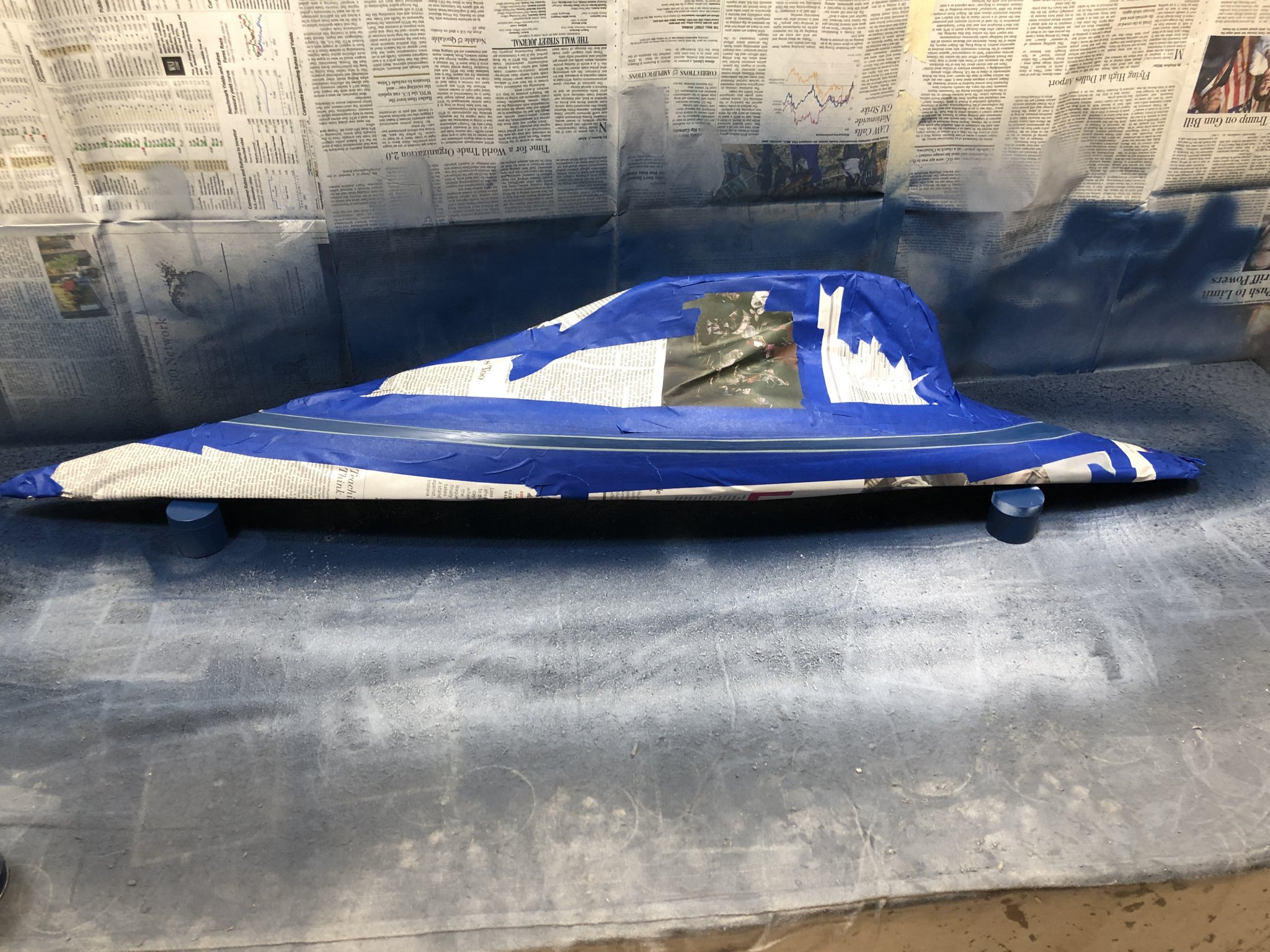
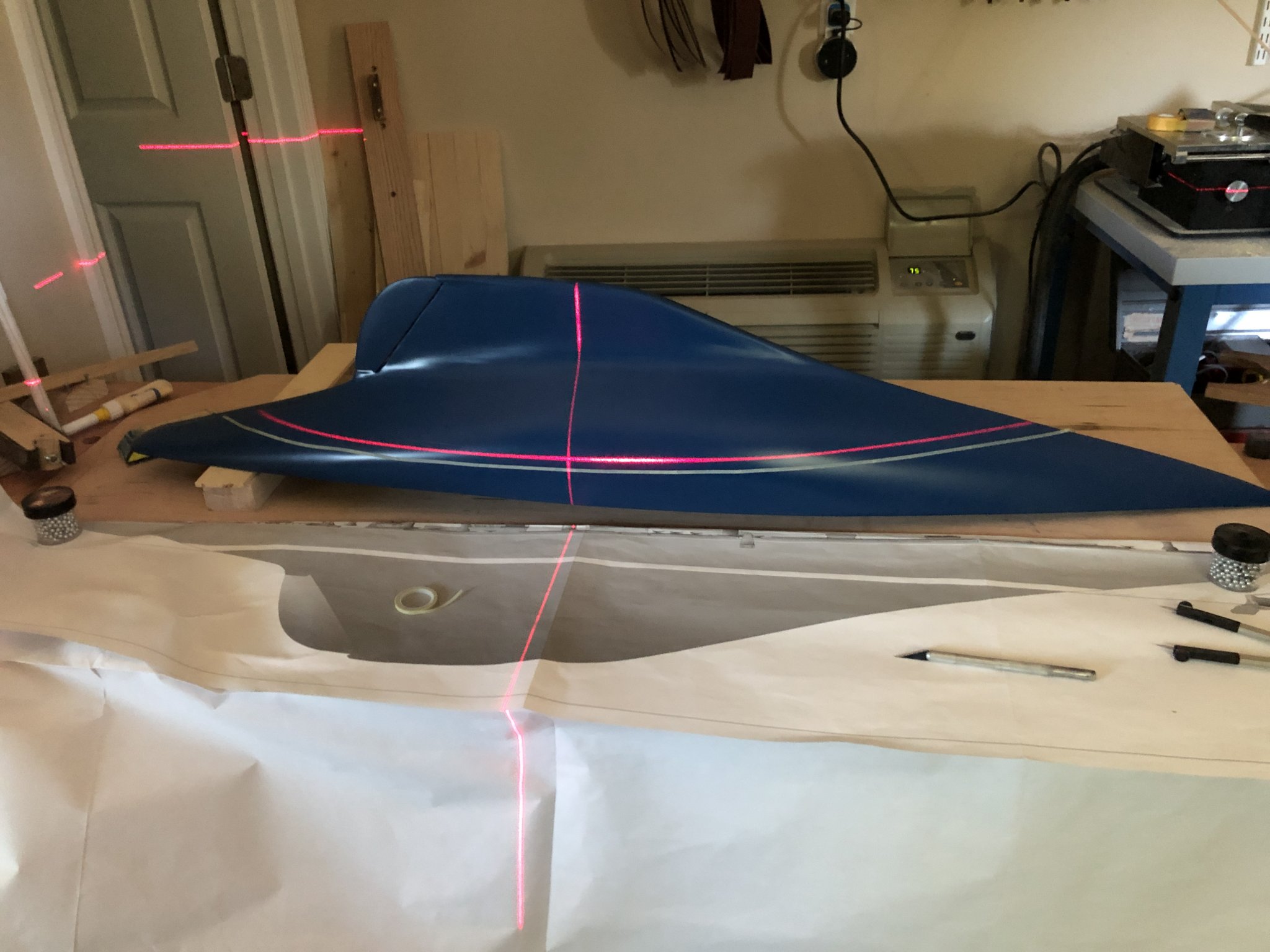
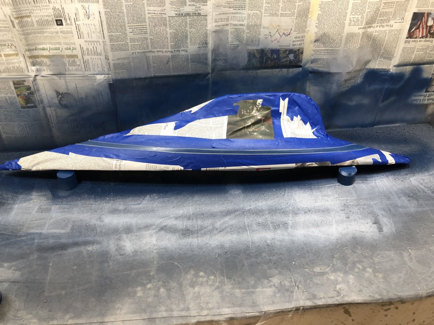
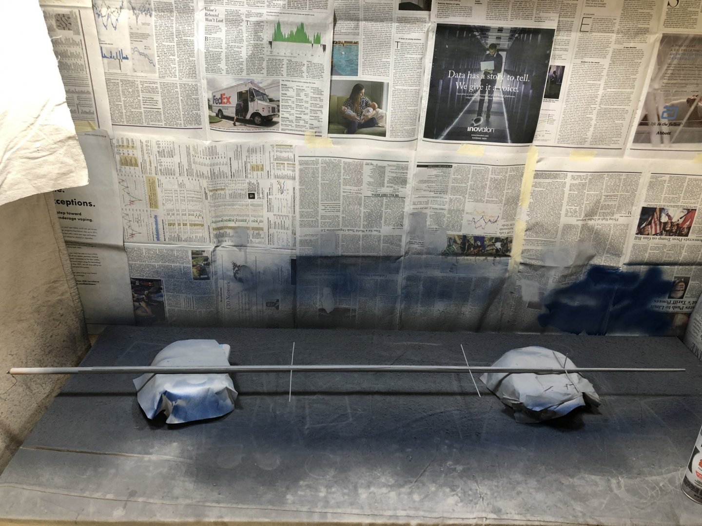
Continued with masking the hull for the waterline stripe. After getting the port side done sitting on the same side as the laser I shifted to the back side for the stbd side and found that much easier. The trick is to get the tape completely red (laser beam is red) just before it hits the hull. I am using 1/8" masking tape which is pretty close to the width of the laser beam on the hull except at the extreme aft end where it is somewhat wider and you kind of have to use your judgement as to where the tape should go. Probably not a really big issue as this area will be very hard to see being well under the counter. I added the two storage bags of BBs to help steady the hull as I applied the tape. They have come in handy elsewhere as well. When I just need weight I put them into a small plastic container. And finally the hull waterline is masked, seams painted with acrylic flat and the rest of the hull protected from over spray (I hope) and ready for the flat white waterline.
-
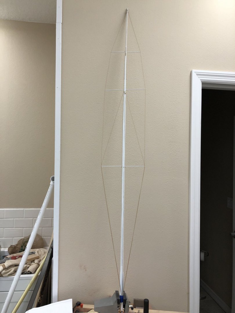
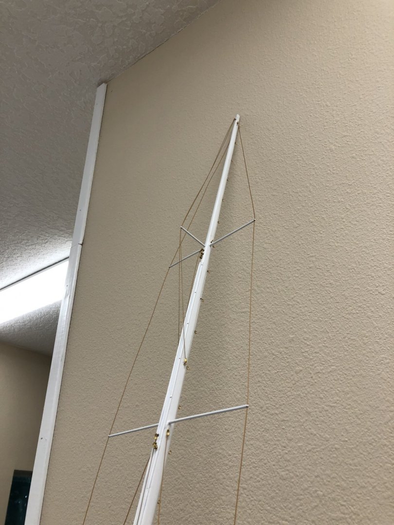
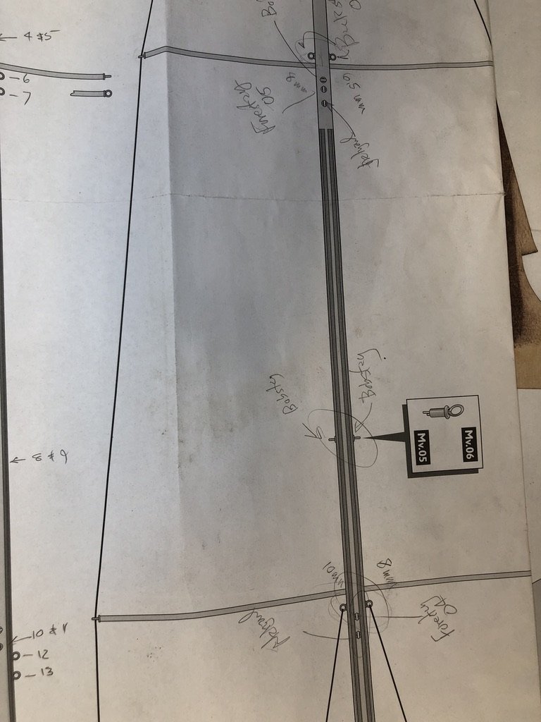
Hull is waiting for additional masking so I decided to rig the bobstays and shrouds on the mast. After thinking about it awhile I decided to go with two bobstays. Seems more symmetric and the instructions seem to imply there are two. Bobstays are .018 Beadalon stain gold with with #2 (.051") crimp tubes. Shrouds are .024 Beadalon satin gold with #3 (.057") crimp tubes. Having some difficulty getting pictures of the mast - it is 5' tall!
-
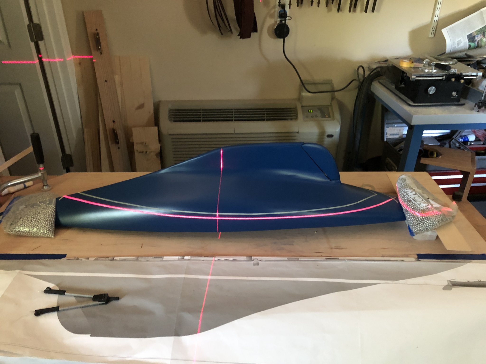
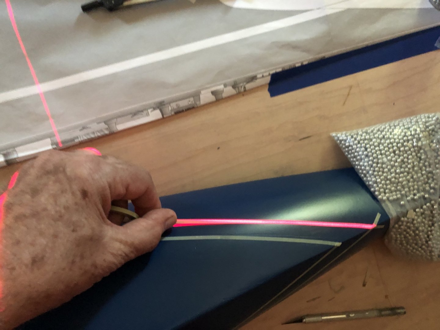
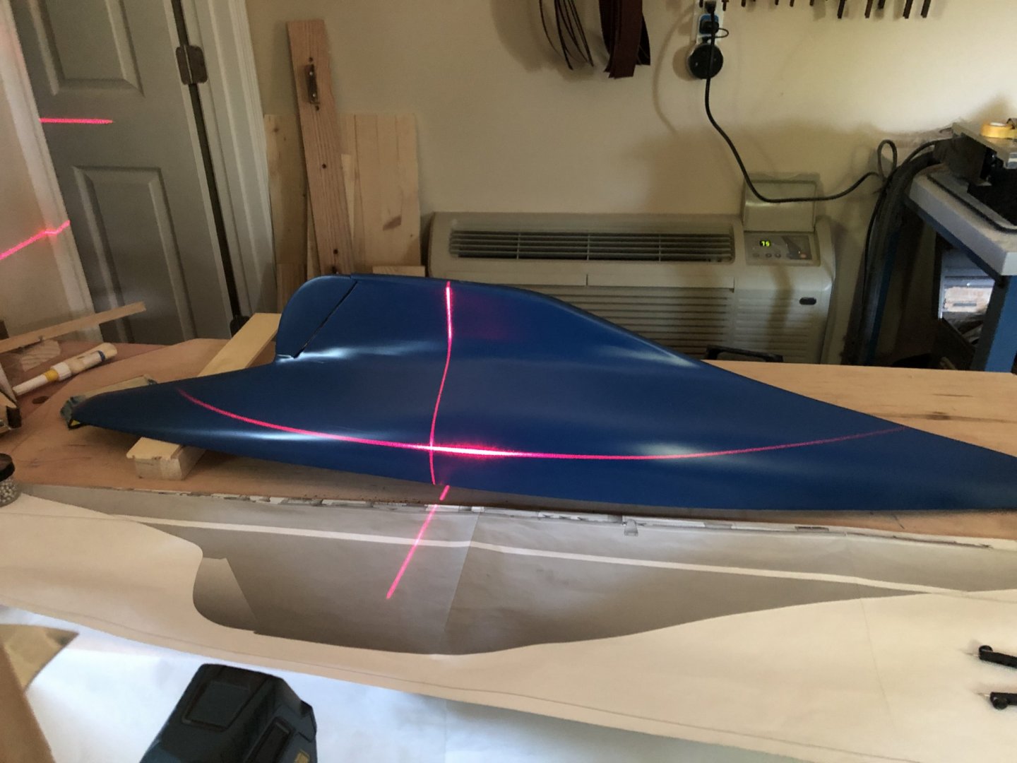
Based on a trial with the gloss finish over the striping tape I decided to paint the waterline with flat white and then put the gloss finish over everything. Which means I have to mark and mask both the top and bottom of the waterline stripe. I tired the instructions version of marking the waterline several times without success. so I resorted to my laser level. I set it up and with the drawing on the bench aligned with the hull measured the height above the hull of the top of the waterline and adjusted the laser line to this measurement. I compared where this crossed the bow and stern with the drawing and adjusted the stern (as it turned out) up about 3/16" to get the c rossing where they are on the drawing. Applying the masking tape was easier than I had thought. Just keep the tape in the laser beam until it is touching the hull then press it down. I adjusted the laser up to the bottom of the waterline as measured on the drawing and applied the tape as before. The plan is to burnish the tape down, apply a thin coat of acrylic flat and then add more tape and paper to completely cover this side of the hull. Then repeat on the other side. Okay - I still can't get the pictures in the correct order. the one with both waterlines (one tape and one laser) should be the last one. The other two show the top waterline, one with just the laser, the other with the tape and the laser both.


-
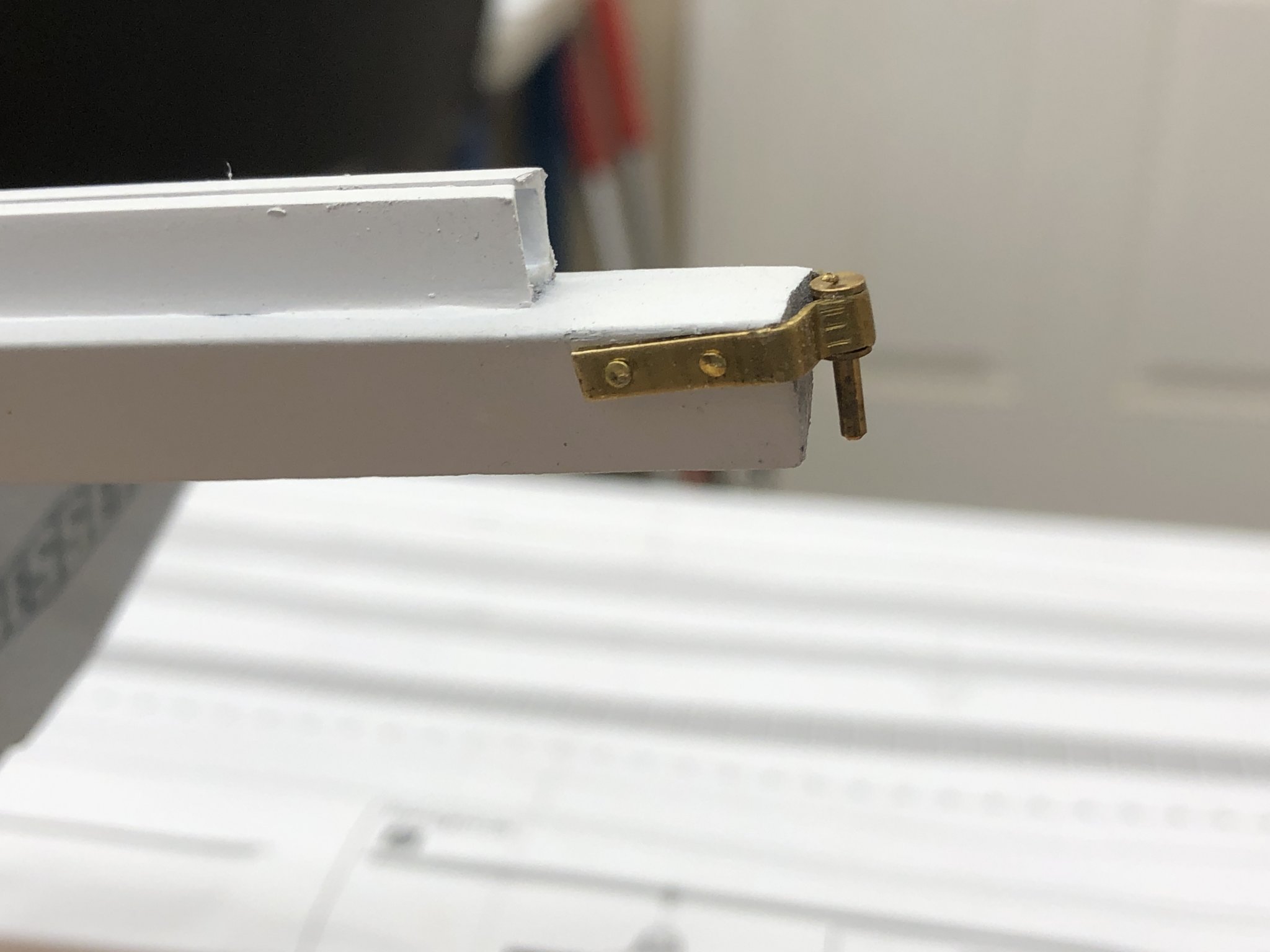
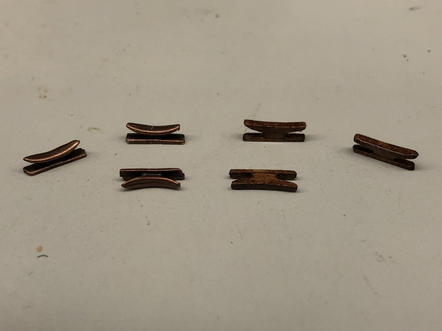
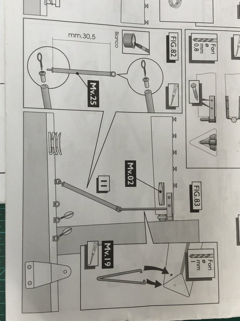
So I spent yesterday evening making the wooden cleats to replace the metal ones supplied with the kit. Probably the hardest part was getting the laser char off the Syren cleats before gluing them to the base. I managed to get 29 acceptable cleats out of the 32 supplied by Syren in the package. Not to worry, more are on the way as by my count I need 34 cleats for the ship. Here are the kit and some of the first ones off my "assembly line". I added two of the cleats to the boom as well as strung the sheet blocks onto the boom. I used Beadalon .018 Satin Gold wire (yes, it is plastic coated but if someone hadn't told me I would not have bothered to look close enough to tell). When the running line is rigged the blocks should hang correctly. I am working on the boom arm tie rod and control arm (instructions page below). The brass rod supplied for the control arm is .06" diameter and the copper tubing is almost 5/64s (.078"). There is no way to bend .06" brass tubing into the sharp "V" shown i9n the instructions and the eyebolts supplied in the kit will not allow the rod to fit through without expansion. And we have brass and copper together again (like on the spreader ends). I am going to use 3/32" brass tubing (I cannot find 5/64") and 1/32" brass rod for these items. The kit supplied eyebolts will fit the 3/32 tubing and the pieces all will be brass (and painted flat white - maybe).


-
Have the eyebolts and gooseneck mounted on the boom. I am replacing the kit supplied metal cleats with 12mm wooden ones from Syren. I do not care much for the color of the kit supplied item. I am trying to keep the number of colors to as few as possible so they do not distract. I will stain the wooden ones mahogany and use gloss varnish so they will match the deck house roofs and hand rails. I have to add a base plate to the Syren cleats as they are not supplied with one. Will use 1/16 X 1/32 basswood as the base since the cleats are 1/16" thick (a little thinner than the kit item but pretty close). One other reason for going to the wooden cleats is I am more confident of getting them glued down to the deck with a wood to wood interface. Pictures of the cleats when I get a few done. For now here is the boom with the eyebolts and gooseneck attached.

-
Nils - thanks. I only had to taper the last plank on each side so much of the credit goes to the kit designer, or maybe the original naval architect.
-
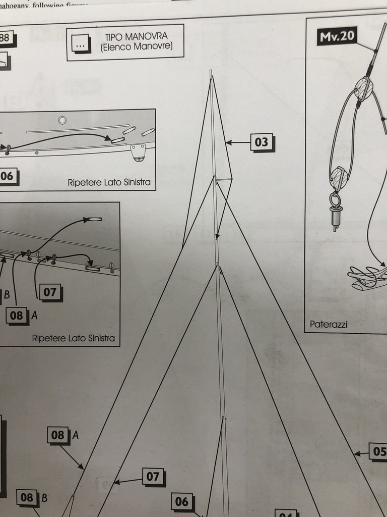
I am adding the rest of the hardware to the forward side of the mast. this includes the blocks for the jib halyards and the eyebolts for the jib stays, bobstays and backstays. Speaking of bobstays there appears to be some issues with them in the instructions. The plans show eyebolts on both sides of the mast between the top two sets of spreaders and below the bobstay tensioner but the instructions show only one stay and it terminates on the starboard side of the mast although the list of rigging says "Bobstays". So I guess there are supposed to be two stays at the masthead, running through the end of the bobstay tensioner and then going to each side of the mast. I looked at the pictures on the box and it is not obvious that there are stays going to both sides of the mast. And there is no detailed drawing that shows the top of the mast. I am planning on attaching as much of the rigging as possible before stepping the mast (which would include the bobstay) so I need to decide on one or two bobstays pretty soon as I plan on completing the mast and boom before starting on planking the deck.
-
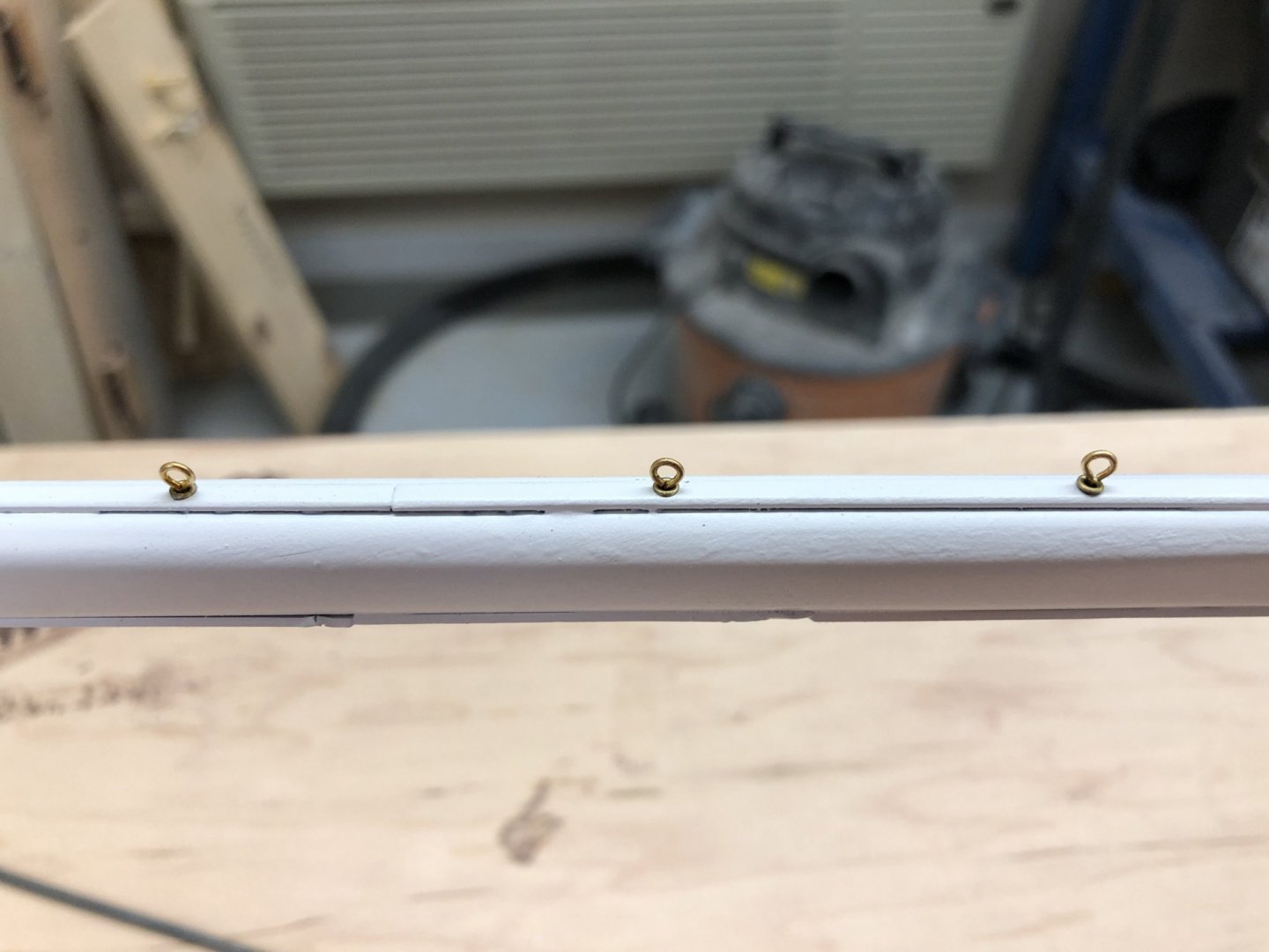
Back from cruise and quick trip to Detroit for funeral - always lots of "fun". Anyway, back to the Endeavour. Still messing around with the hull. Next step is to mark the waterline and then put the gloss coat on. I decided to use striping tape for the white at the waterline. I fear masking and painting is in the "too hard" pile. Maybe next time when I am using the airbrush to paint the hull and have easier access to touch up paint. So while I contemplate how to mark the waterline I decided to work on the mast and boom. First step was to add the eyebolts for the main sail on the after side of the mast. I first soldered a 1/8" eye bolt from my collection to the "holder" that comes with the kit, cut off the excess and mounted that in the mast after drilling a #54 hole in the appropriate locations. I thought about using epoxy to glue them into the mast but they were a "press fit" (some pressed harder than others) and since they only hold the mainsail I thought that overkill so they are just held in by friction with the mast. We will see how this works out when mounting the mainsail. So here is the mast and a close up of the eye bolts.

-
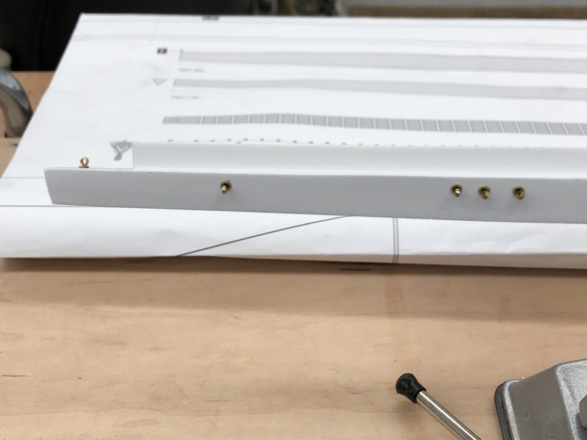
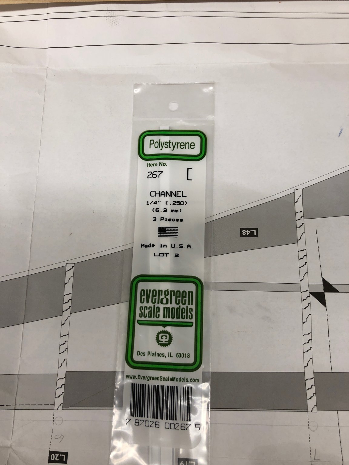
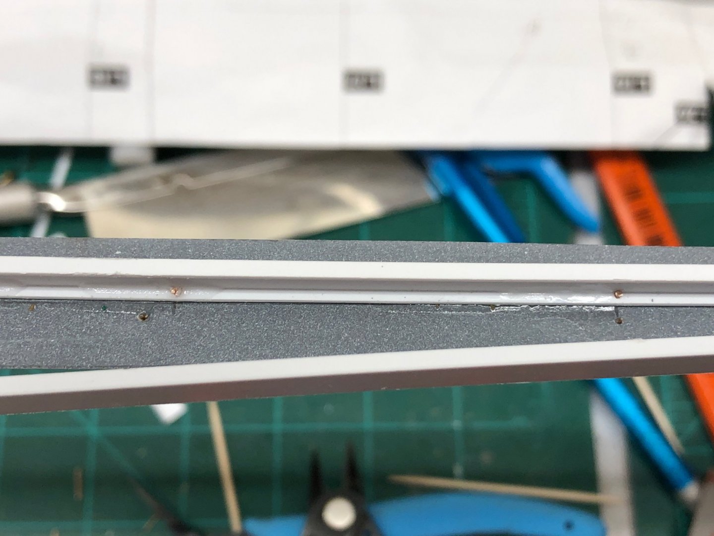
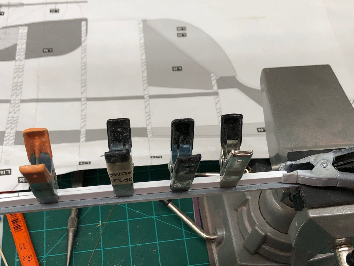
The boom. I got the Evergreen channel pieces I ordered and after looking them over decided to go with the 1/4" pieces. The idea (instead of 58 H channels and 58 split rings) is to mount a section of channel with the leg on the boom on each side of the boom centerline covering the same length of the boom as the 58 "H" sections would have. I mounted the channel down one side and used .025 phosphor/bronze pins every 50mm to hold the channel in place and used medium CA to glue the channel, pins and boom together. Here is a picture showing the installation. After applying medium CA to the area at the bottom of the first channel, the second channel is placed next to it and secured (carefully - it is easy to get one channel on top of the other - don't ask me, how I know) with clamps (pick your weakest ones that will fit). Unfortunately the Evergreen channel does not come in long enough pieces to cover a side so a joint is required. I decided to not have the joints in the same location but it probably won't matter in the end as the sail will make it hard to see both sides of the boom at the same time. I plan on adding a bolt rope to the foot of the mainsail and slide than between the two channels on the boom. The tops of the channels are not glued together (hopefully) and the sail is stiffened with 50/50 glue-water so all should be good - we will see. If all goes as planned the bolt rope will continue up the luff and help contain whatever method of attaching the main to the mast is used. The instructions show using eyebolts but others I have seen put the eyebolts in the mast and attach the sail to the eyebolts with small line. I have not decided yet but it is on my mind. Here is the boom in the paint booth getting the final coat of flat white.

-
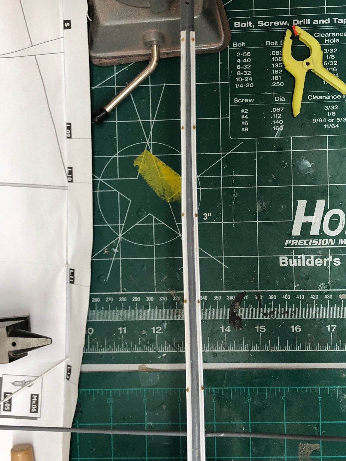
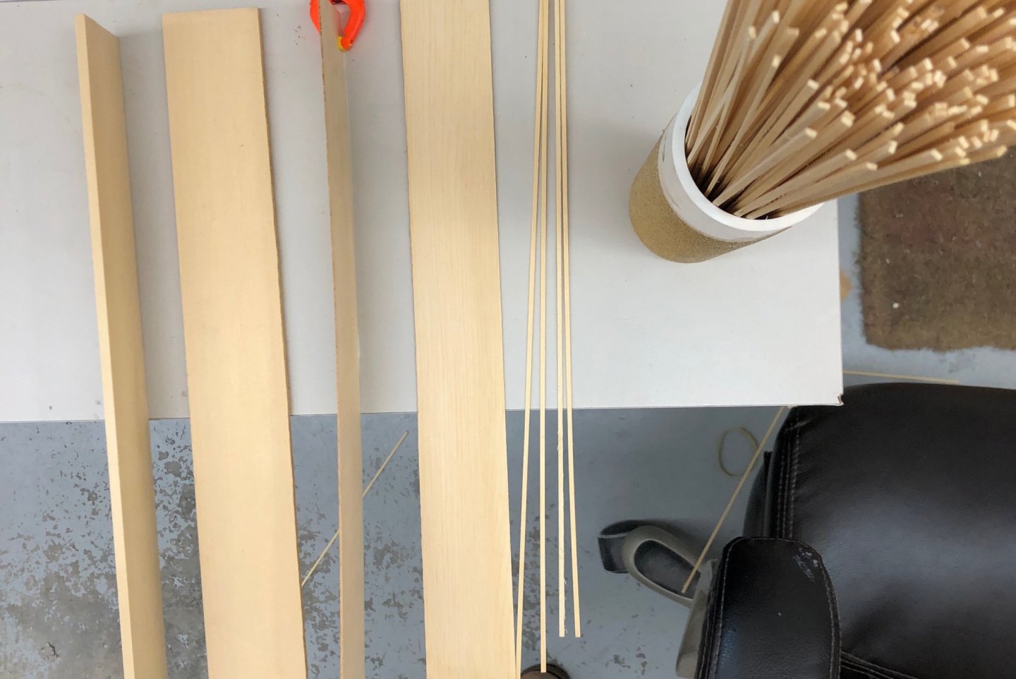
Getting ready for the next step - deck planking. As I mentioned previously I am going to use Alaskan cedar (from Syren) to plank the deck, as I did the tops of the cockpit and some of the other deck furniture. The starting point are the 2" X 14" X 3/16" "planking blanks". They come in a variety of thicknesses. I choose 3/16 because it can be split lengthwise to get two "super planks" from each blank. As it turns out I have to trim about 3/32 off each of the blanks (now 1 29/32" X 14" X 3/16") so that my 4" table saw can cut all the way through in two passes (left side of photo) Then each "super plank" goes through the thickness sander which produces the 1mm X 1 29/32 plank in the center photo. The thickness sander (from Model Machines) produces a tolerance of plus or minus .03mm using the course grit side. These 1mm planks are sliced into 2mm (more accurately 2.13 to 2.25mm) planks which you see on the right of the photo. I plan to check all the planks and discard any that are more out of tolerance than the range above. I also need to create some more or less 1mm X 1mm planks to fill in where the hand rails which are 1mm thick are on the deck.
-
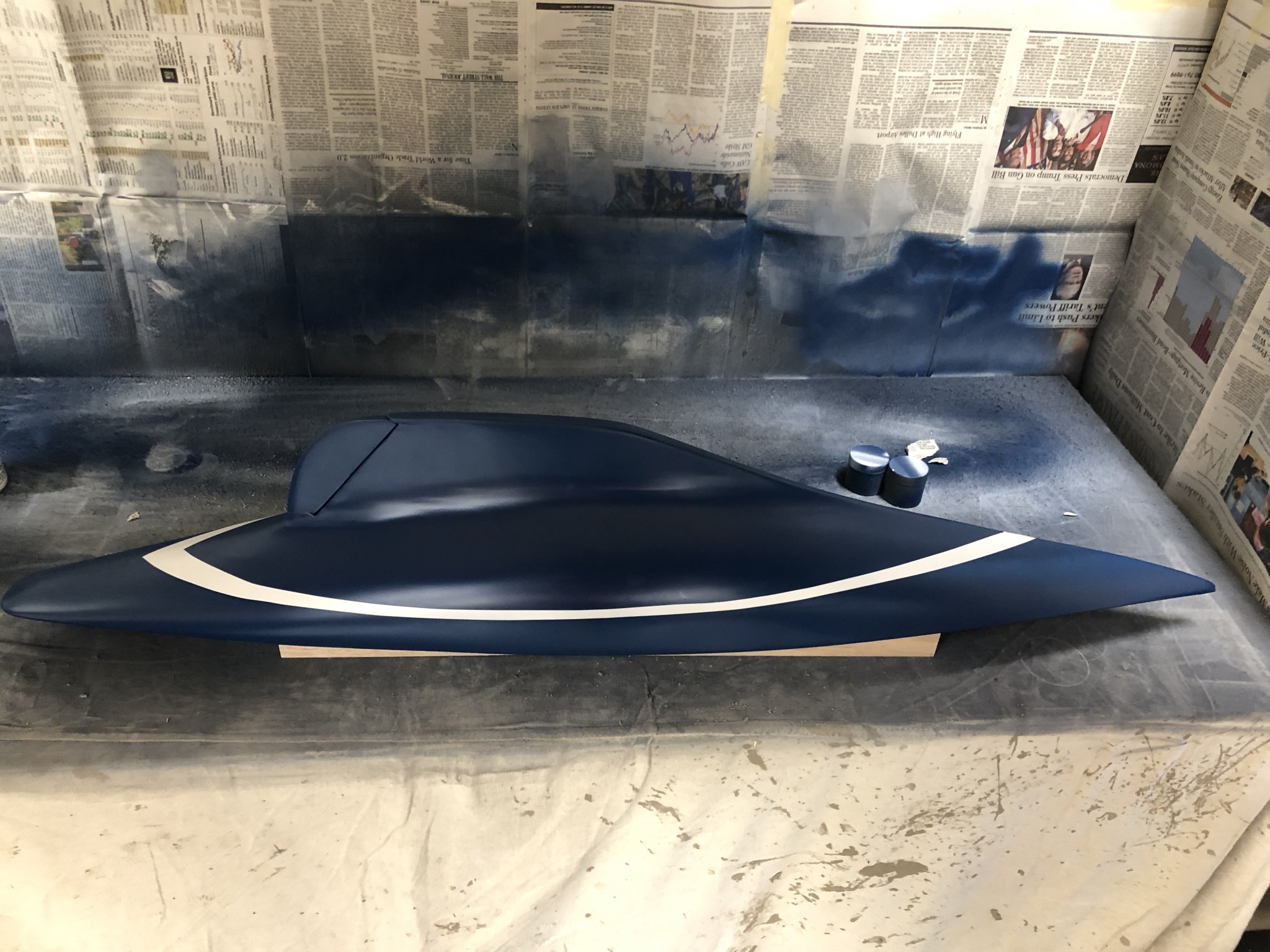
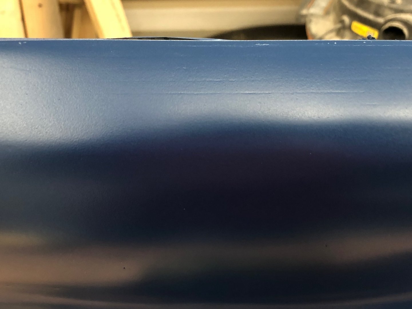
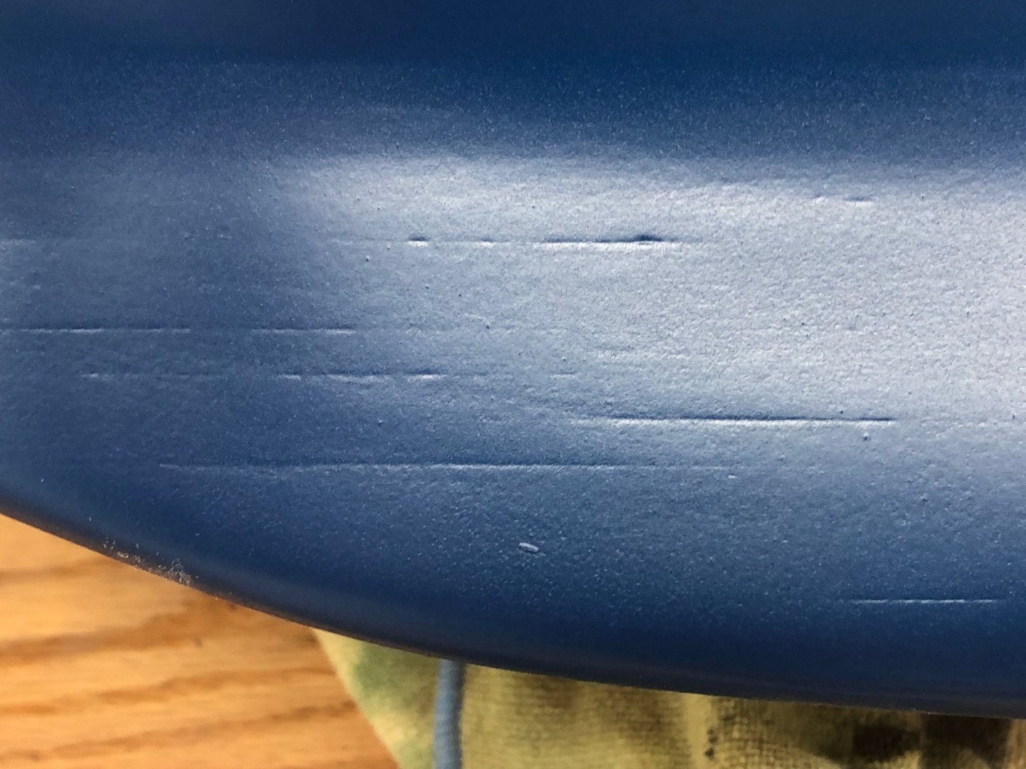
I sanded the first coat of blue with 800/1000 grit (it really loads the paper up in a hurry) and then another coat of blue. There are still areas where you can (just barely) see the underlying wood seam and areas on the fin where I clearly did not get everything as smooth as I would have liked but they are not too noticeable since they are in the shadow of the hull and I know I tried to fill these at least twice without complete success. I am off for a week to cruise the Caribbean so the gloss coat will have to wait until I get back. Will give everything plenty of time to dry completely before starting the deck planking.
-
I got the turnbuckles I ordered, decided (at least until I see how it looks on the model) to use 22mm ones for the upper shrouds and 18mm for the lower. I had to use the larger split rings because of the distance from the edge to the hole in the brass "chain plates" provided in the kit. I am considering changing to brass (actually gold colored) wire for the shrouds instead of the silver I have now. I ordered the gold Beadolon wire in case the silver does not look "right" with the brass turnbuckles (and I have not seen them in anything but brass).
-
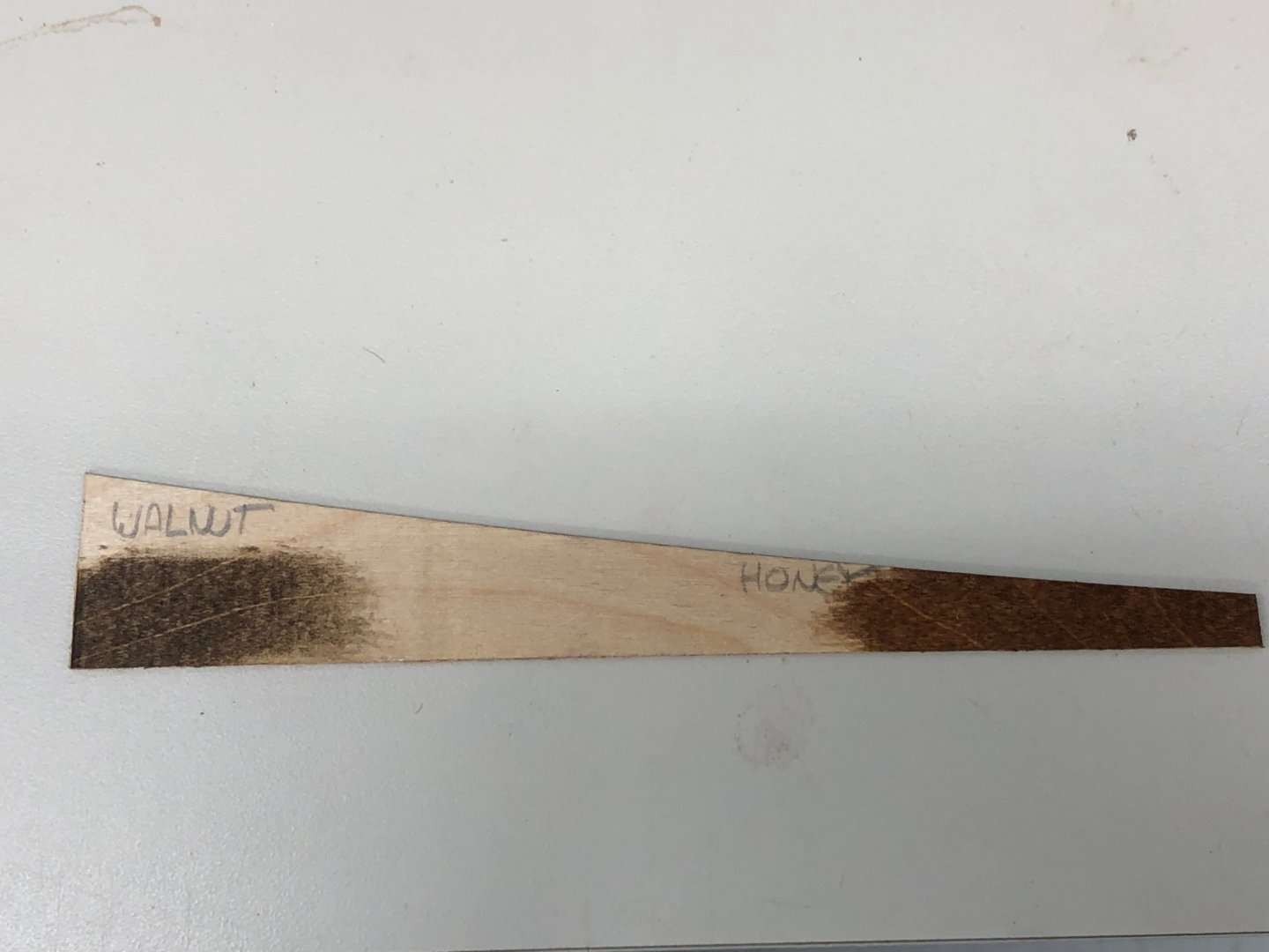
The mast has received its last primer and while waiting to put on the first finish coat (flat white) I started thinking more about the deck and associated pieces. The kit provided handrails, which are attached to the deck 14mm (more or less) inboard from the deck edge planks, are laser cut from plywood that is 1mm thick. That will present somewhat of a challenge since the deck planking is 2mm wide, so there will be a need for 1mm wide deck planks to "fill the gap" where the hand rails are installed. In any event, I think it will improve the look of the model if the hand rails are stained to match the mahogany elsewhere on deck and cut a piece of the plywood to see if any of the stain colors I already have will serve or I need to go get some "mahogany" stain.
-
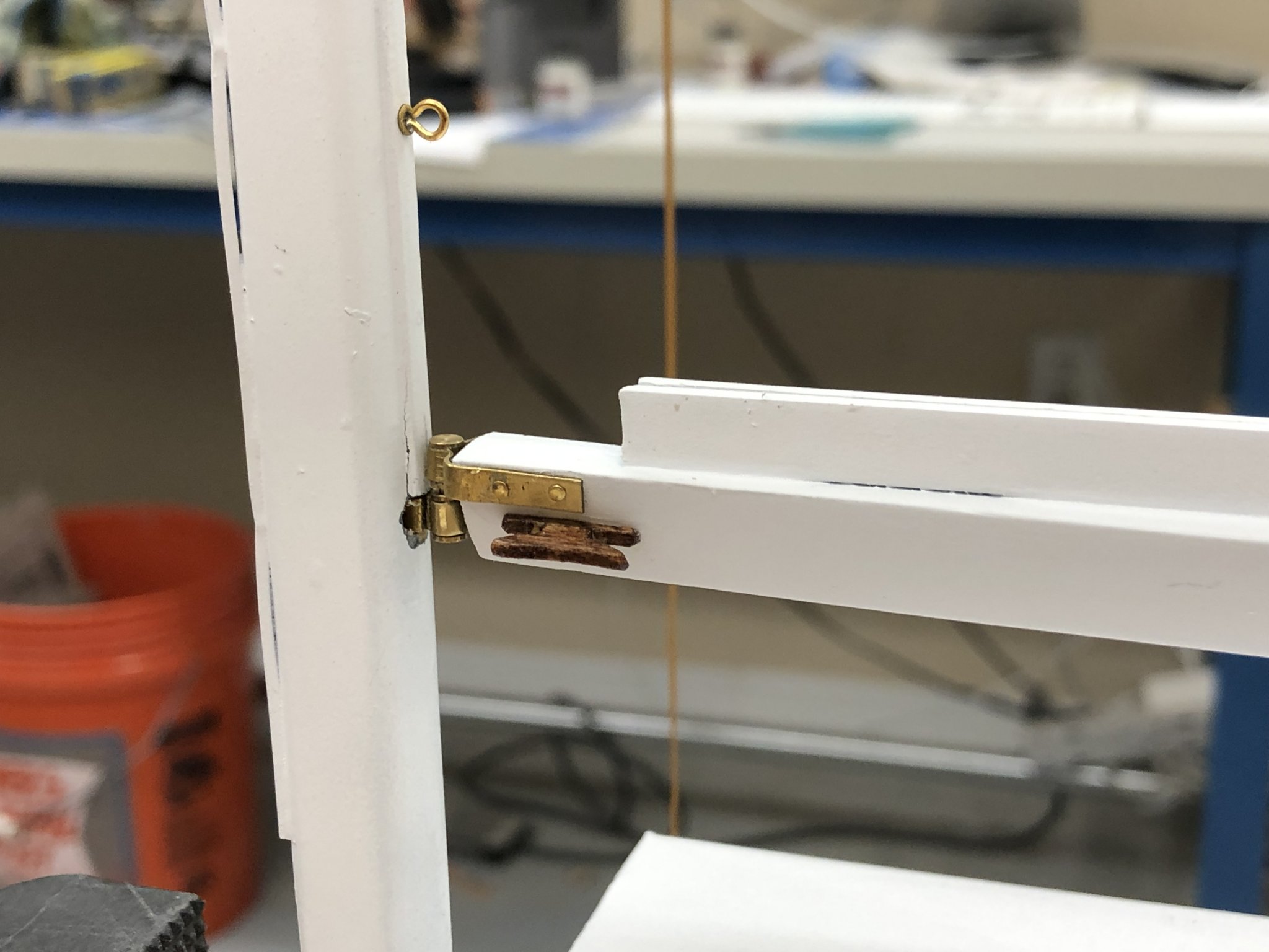
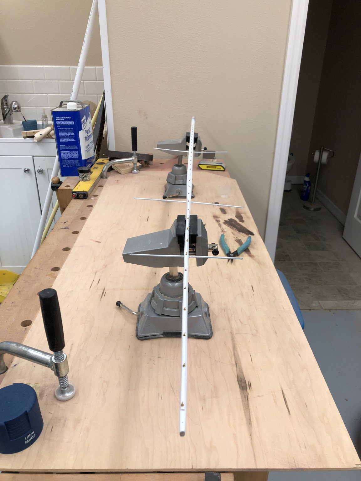
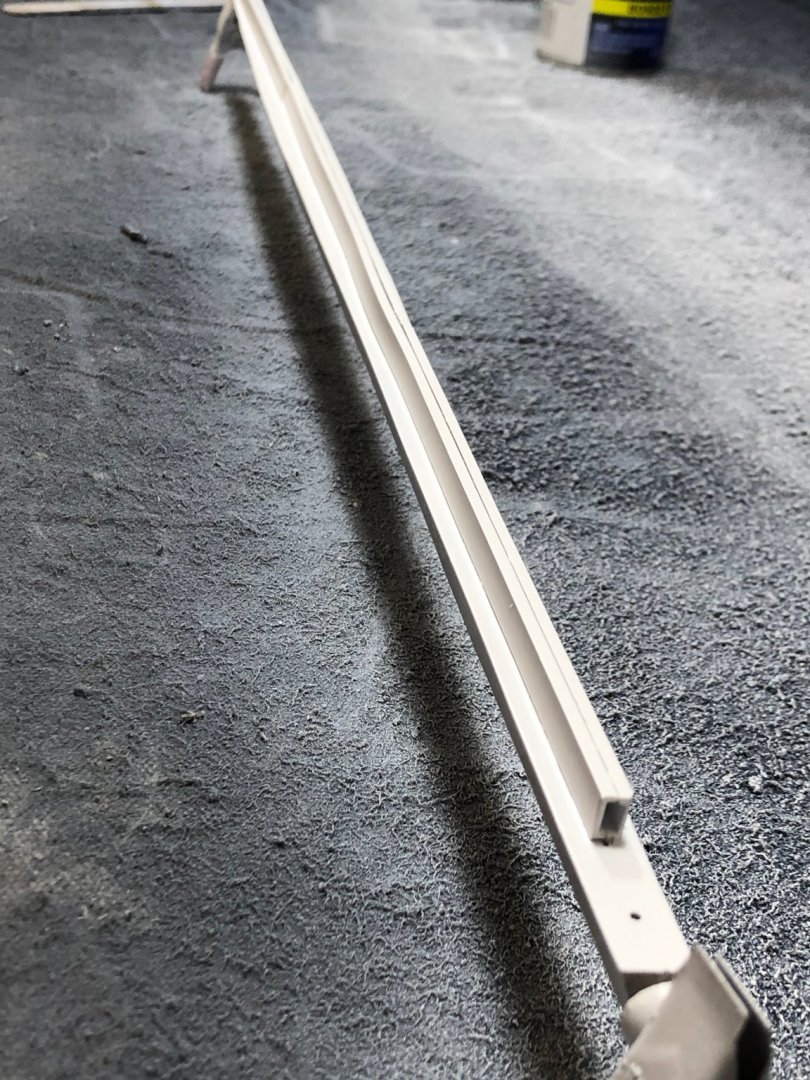
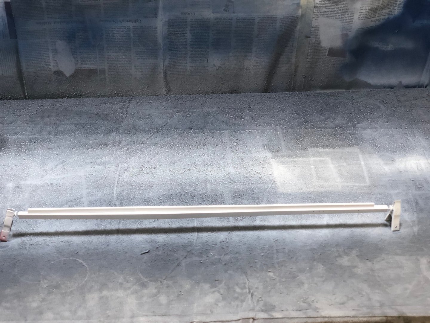
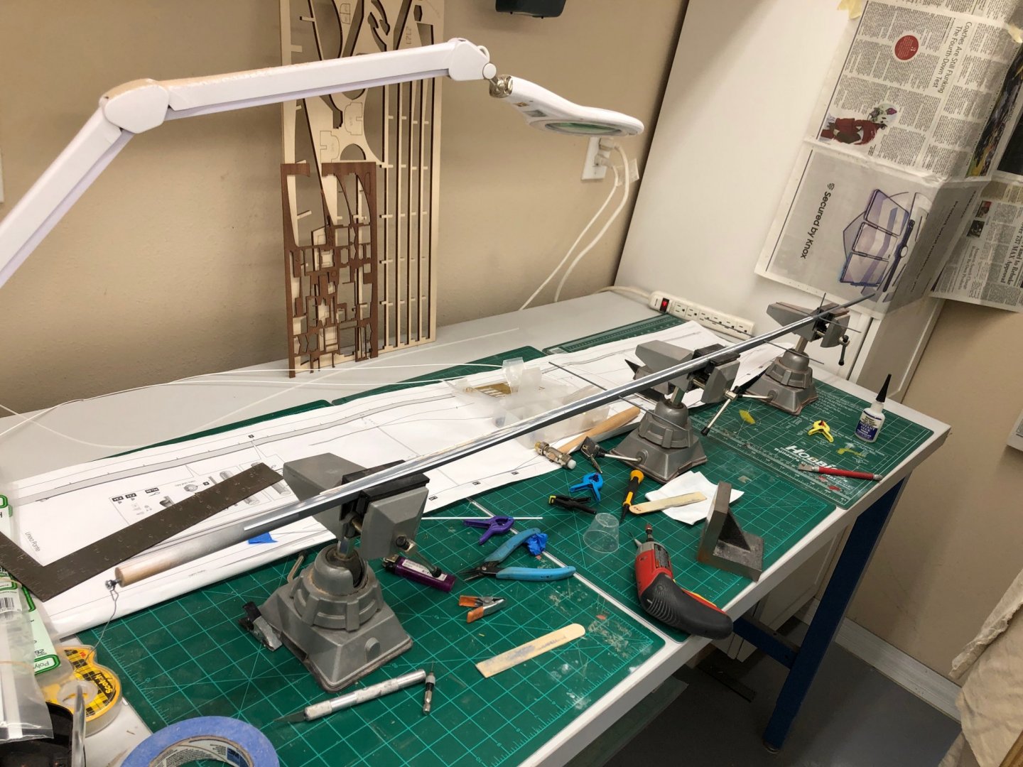
Working on getting the tracks attached to the mast so it can go to the paint booth. As I have mentioned getting these tracks attached has not been without its challenges. Not the least was how to hold the mast while doing it. I finally held it with the three vices I used to hold the hull when it was being planked. This seems to work okay but it does put the spreaders in a vulnerable position. If I had it to do over I would not add the spreaders until everything else on the mast was done and it was ready for primer/paint. Here is the mast in the vices and the tracks at the top of the mast.

-
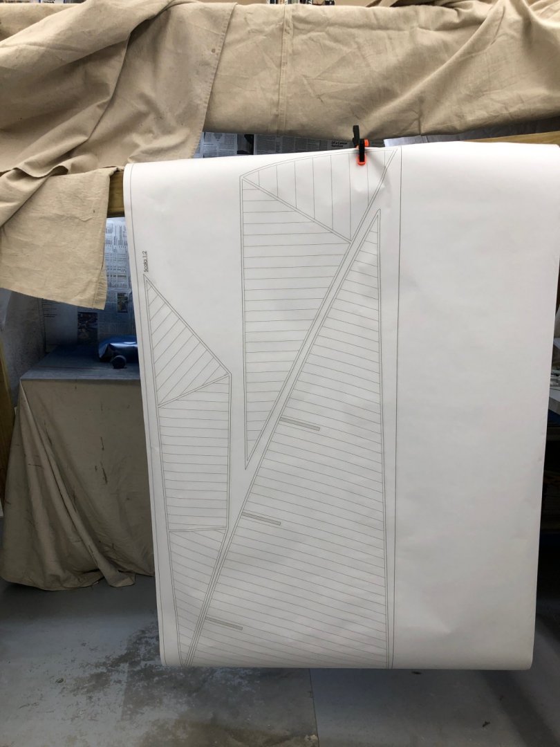
While looking over the drawings I noticed that the plans for the sails are only half size. I decided that full size would be much easier to work from as no math is required. So I took the provided plan to a FedEx office shop nearby and had them scan in the sail plan, scale it to full size and print a few copies. My girl friend thinks she can sew the seams (although the instructions indicate they are drawn on with pencil) so we are looking for some material similar to what is provided with the kit to experiment. At smaller scales I think sewing fake seams is impossibly out of scale but at 1/35 it might not be too "over the top". Here are the sail plans at full size.
-
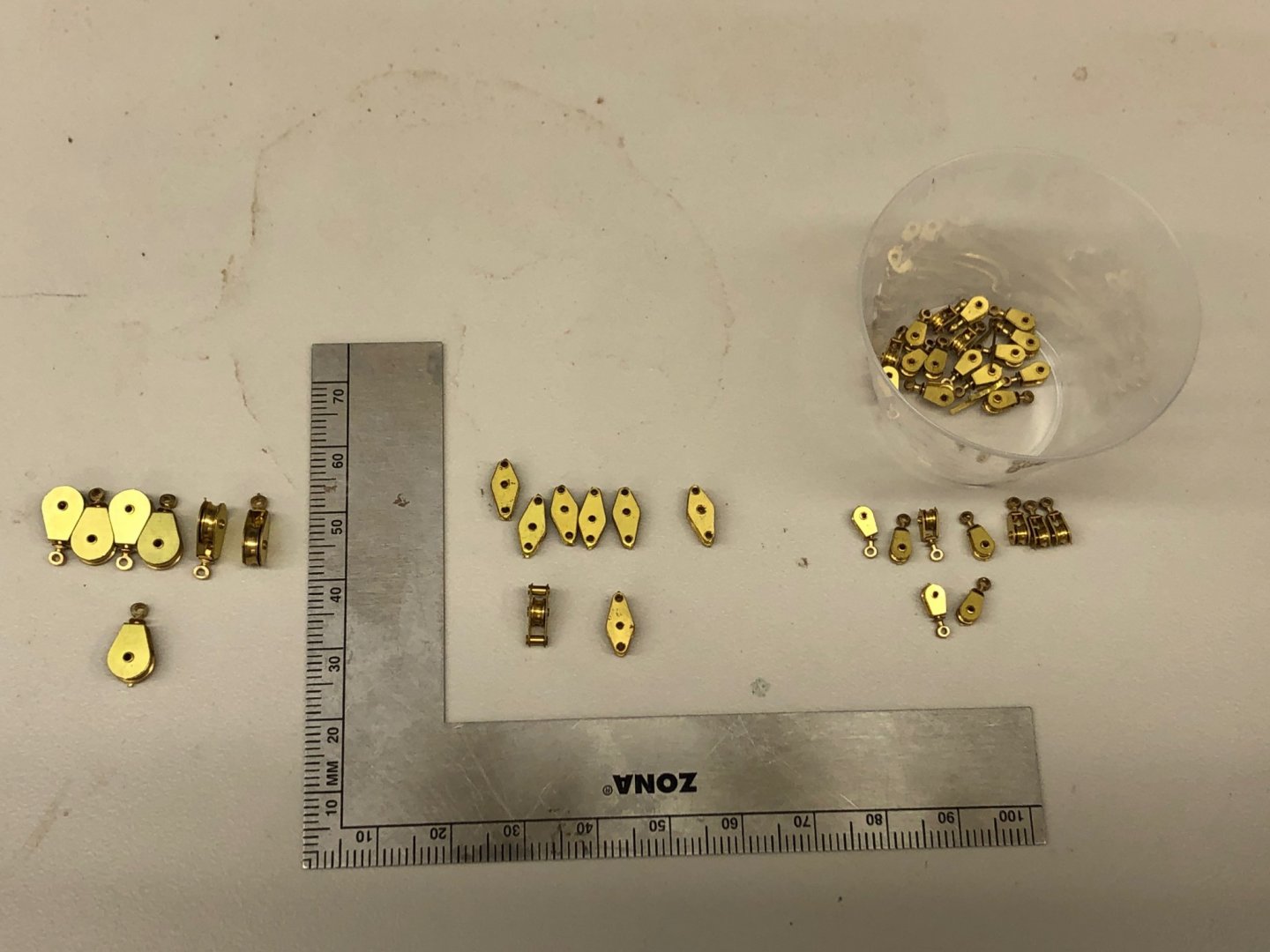
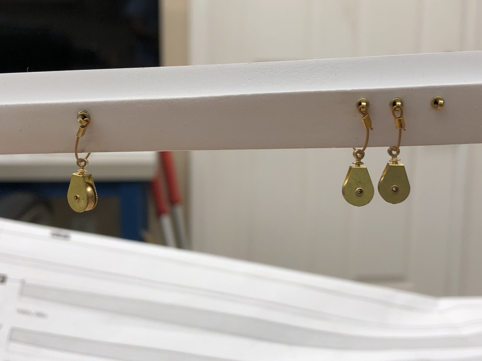
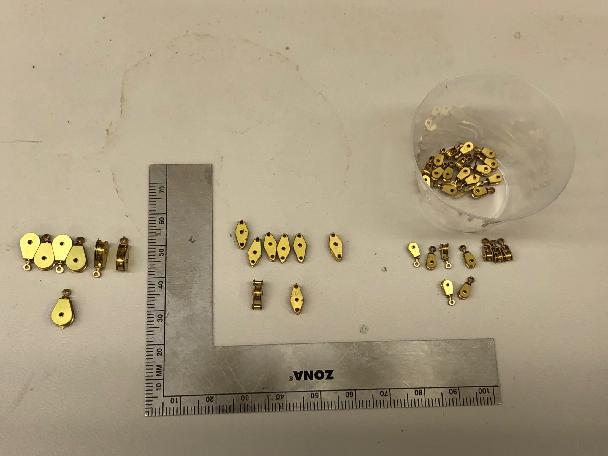
While looking through some some of my collection of hardware I came across a set of brass rigging blocks. I do not remember where (or why) I bought these but I am sure it was 7-8 years ago. Given the size of the models I usually build I think it unlikely I would ever use these anywhere but on the Endeavour. Luckily I had just done a cataloging of the rigging and blocks required and was able to determine that I had enough blocks of roughly the right size and configuration to meet all of the block requirements so these are the blocks that will be used. All of the sheaves turn and the attachment ring (or those so equipped) actually turns so no worries about attachment orientation.