cookster
-
Posts
416 -
Joined
-
Last visited
Content Type
Profiles
Forums
Gallery
Events
Everything posted by cookster
-
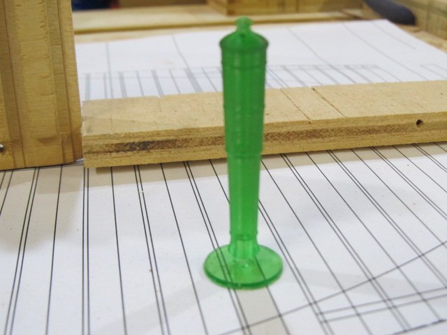
Hello folks - I don't intend to hijack this thread, but here are 2 items I printed, in resin, with my Photon S. These used the stock slicer settings, but I am going start tweaking things as I get more into it. These used the Anycubic resin. I also am making some parts that are for real world use (not models) and I have switched to resins from Siraya Tech. I encourage you to look at and research other resins, there are lots of them out there. Egilman, enjoy your new printer! These are for 1:48 scale (next to an inch ruler) both were just tests of what could be done...

-
very quick update, still working on square frames - but only 7 to go. yee haw.... Looks like I have rear cants and fashion timbers in my near future, wonder how much trouble I'll have with those.... Thanks for looking in! PS - if we ever have a messiest workspace/table area contest, I want to enter. I'll win for sure, LOL

-
Thanks Jeff. I built furniture as a hobby for years so all I had to do was scale down... As far as my Conny, I've got a 3d printer now and I've already got many ideas of things I could print to make that build better and easier. Can you say quarter galleries?
-
Hello Jeff, I too bought your wood kit for the Conny a few years ago, plus other wood as well, You were the inspiration for me to start milling my own wood, when I saw it could be done I figured I could do it too. Which I do, lol. I had started my Conny build (also using Bob's practicum) and then fell to the dark side a started a scratch build. My Conny now sits alone waiting for me to return. I must say looking at your log has rekindled my interest in my own build. Your build looks great, I look forward to watching you progress. Good luck and happy building!
-
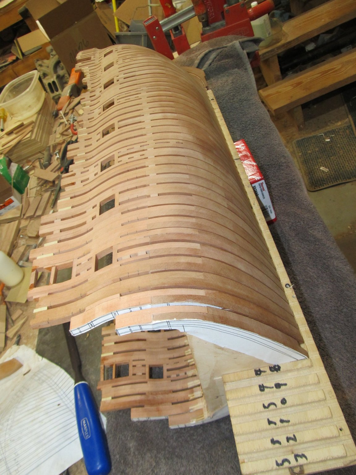
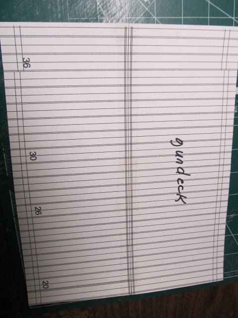
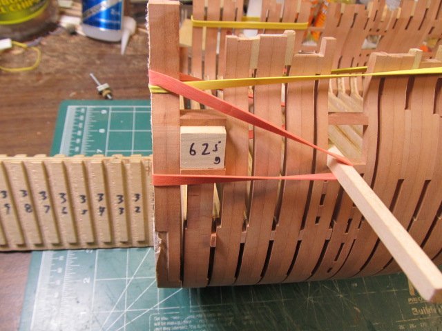
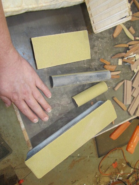
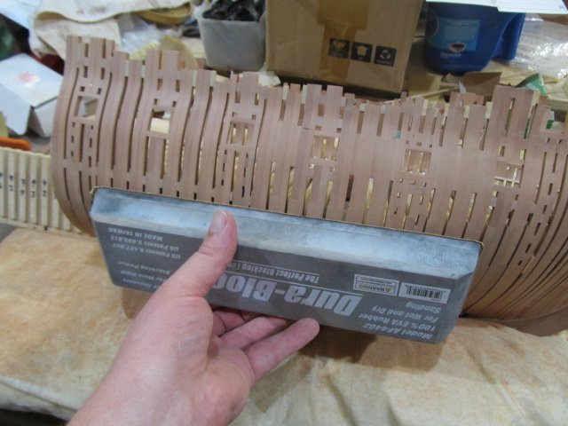
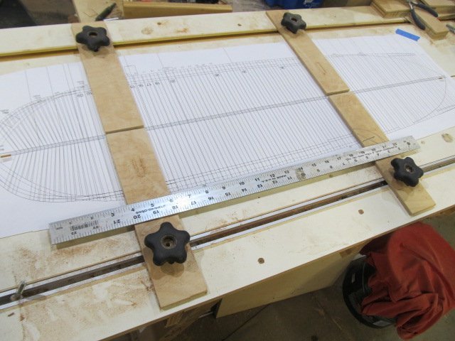
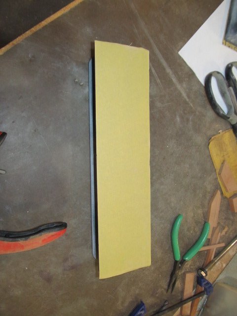
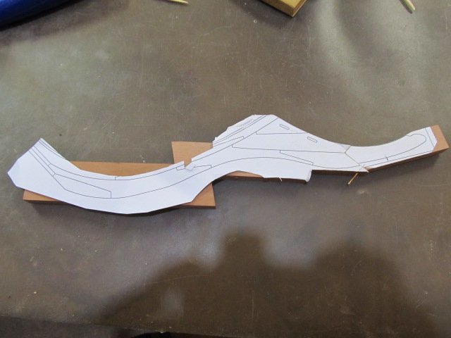
Here's a few more of the tools and some tricks I use. I print out the deck profiles on cardstock, then use them as template when fairing the frames. I did not do this on my version 1 of frames and that's one one of the reasons I screwed them up and over sanded. These patterns really help! When framing the gunports, I set the sill in it's location, then use a gauge block I cut to place the header. This way it's accurate every time AND sits square to the sill. When fairing (sanding) I use these sanding blocks intended for autobody work. They are great for fairing outside the hull. Inside is a little trickier, but they can be cut down if that helps. The 2 round ones you see below were cut from a single block so I could sand the tighter radius as the hull turns. . Oh, and I finally printed the full length deck plan. That's a 24" rule as a reference. Another cannon pic...
-
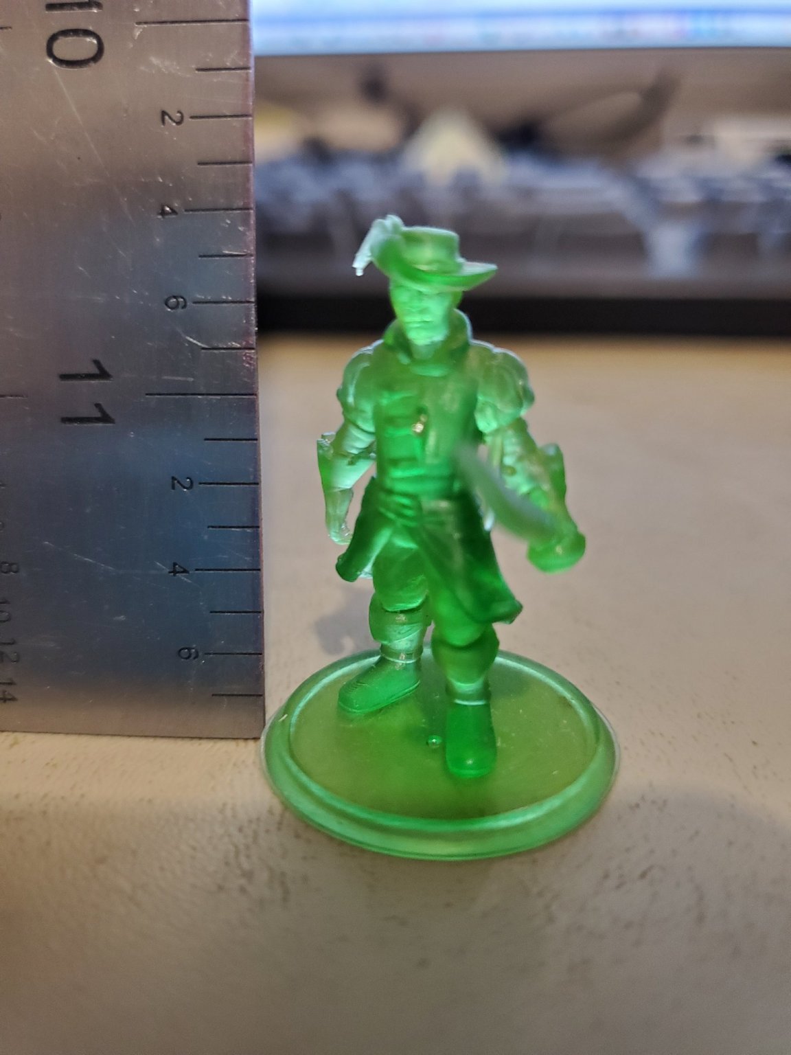
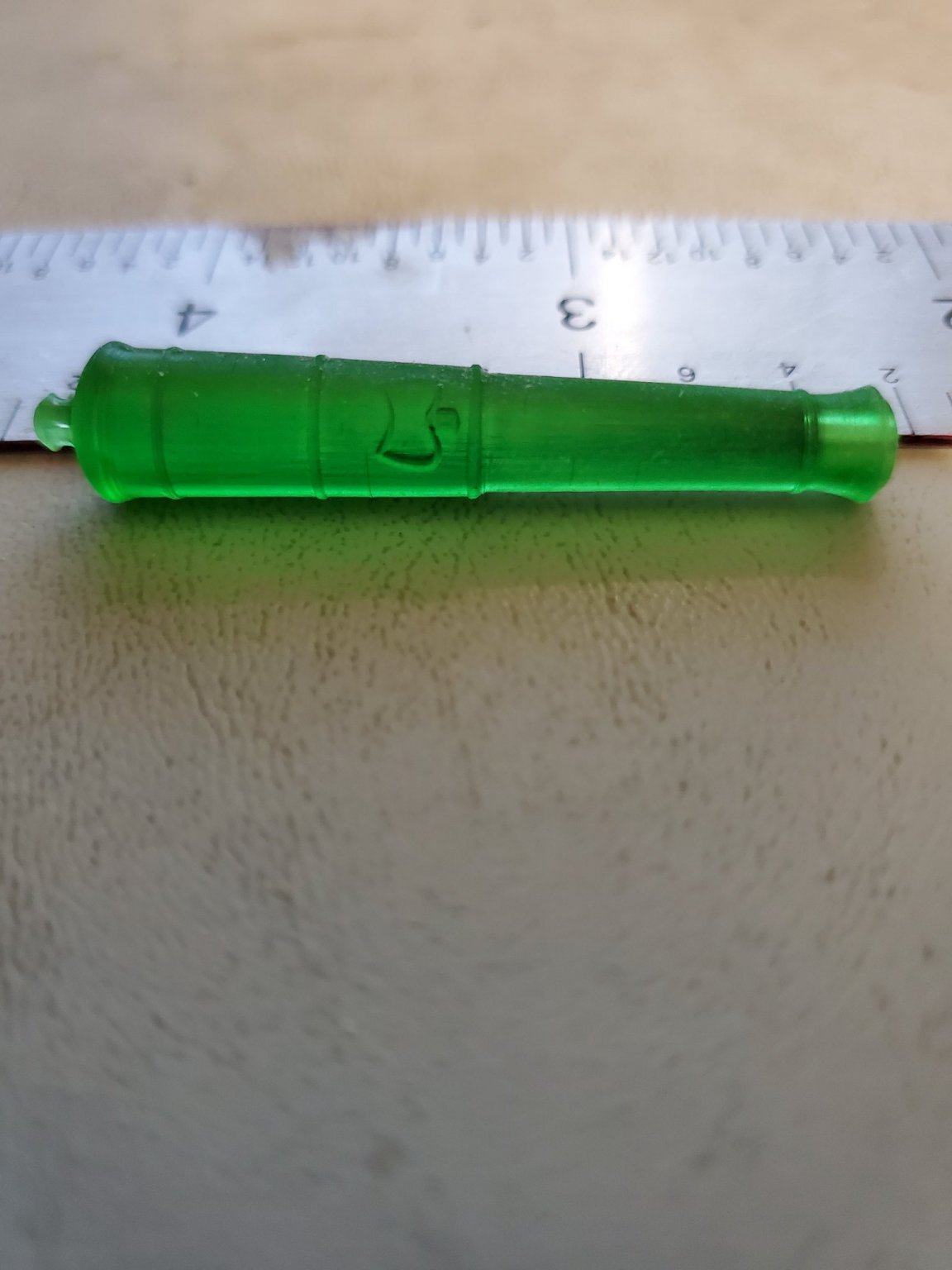
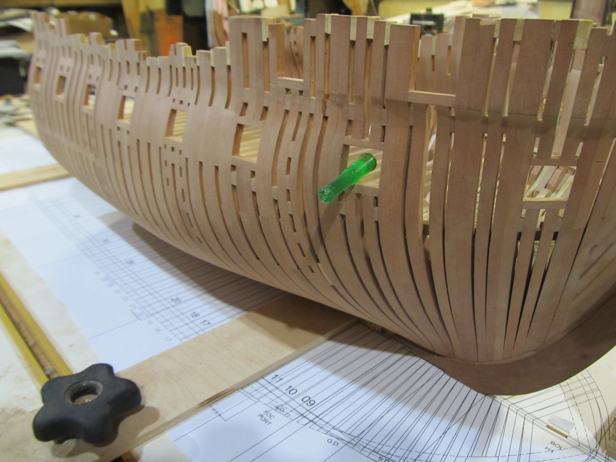
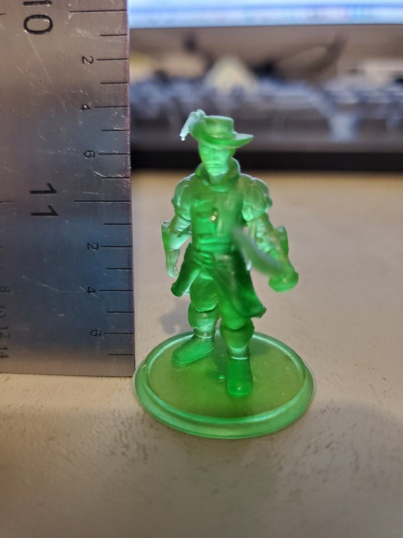
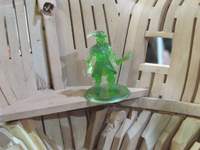
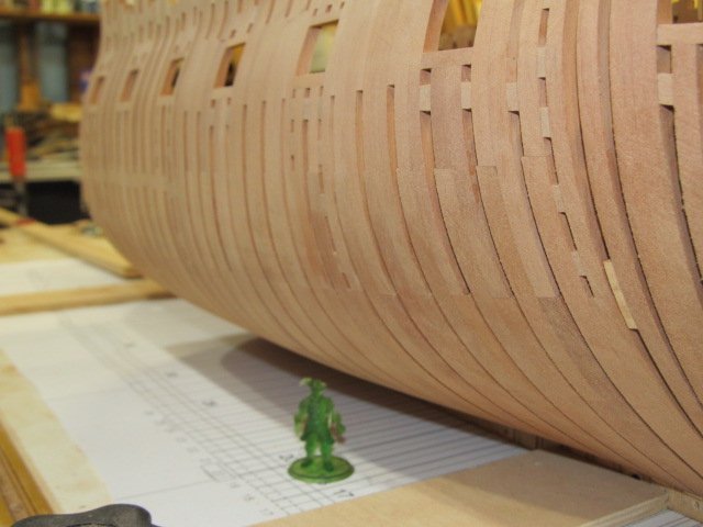
well, I'm still adding frames. Also, I finally got my 3d printer up a running. I've printed a few things so far only as tests, but so far I'm pleased. Here's Pirate Cap'n Green Legs in his 1/48th scale glory. This was just a test (got it from Hero Forge), I do intend to model up a proper US navy figure at some point and print him out. I also drew up and printed a 12 lb long gun, which Essex did carry at Valparaiso. My plan is to finish the model ( trunnions and such) then print a master, and make a mold(s) and cast what I need. I don't plan to make a separate thread just for 3d printing stuff, but if there winds up being enough interest or questions I may. It just depends. I also received the CNC router I ordered a week or so ago, so I'll need to work with that at some point and make some stuff. Anyway, more build pics. Till next update.... Gratuitous cannon pic... Here's the side that will be planked over, I realized I don't show it much.
-
Pucko, thanks for the link. I watched a few and will watch the rest. Good info!
-
Thanks Pucko, I already ordered mine earlier today and will have soon, as a late birthday present to my self As far as the software, I've been using CAD and 3D software for 30yrs, so that part is no worries for me. I have a Sherline mill that I was going to convert to CNC, but that's over $1000 to do that. When I saw this CNC router, at that price, I had to get one to try. I've never used CAM software but I know what G-code is, so I just need to figure out what this machine needs. I use Solidworks, so I have the CAD side covered. I can't wait to make some stuff!! Thanks again for answering PS, I didn't get the laser, if I ever want to play with one I can add it later.
-
Hello Pucko, I'm thinking of getting one of these. Do you still like yours?
-
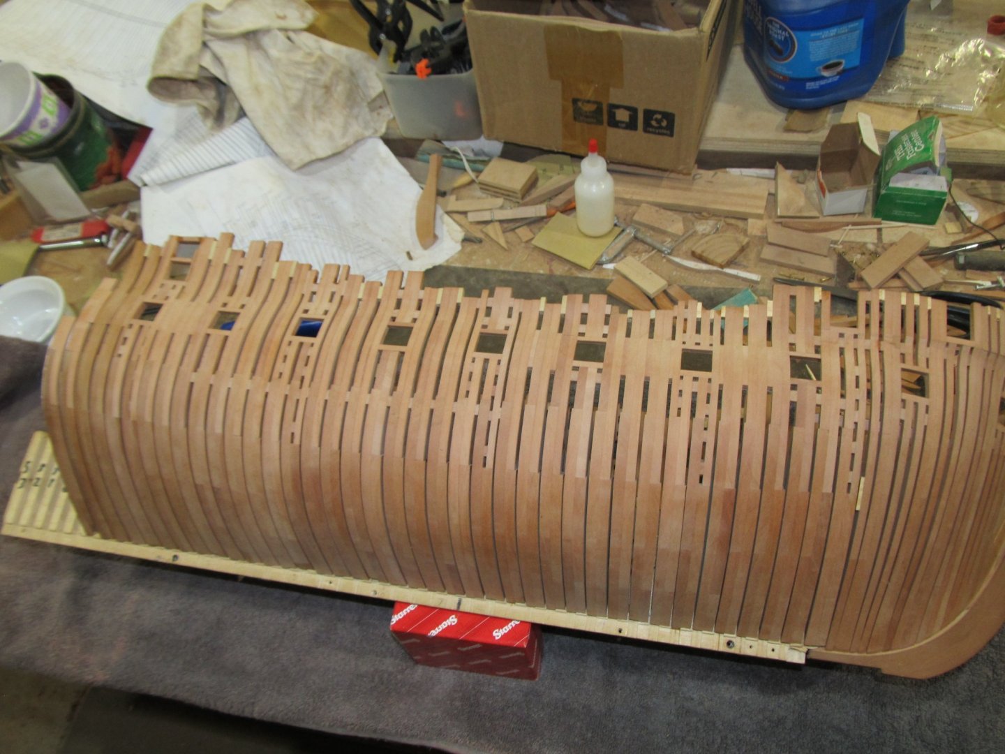
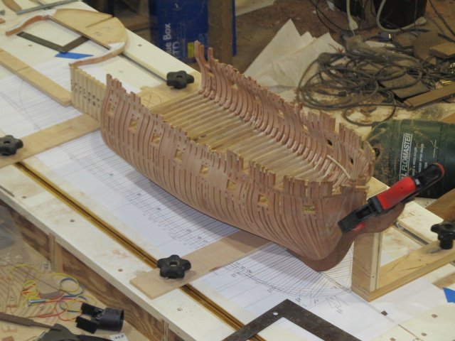
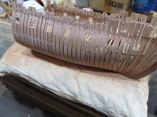
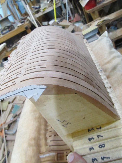
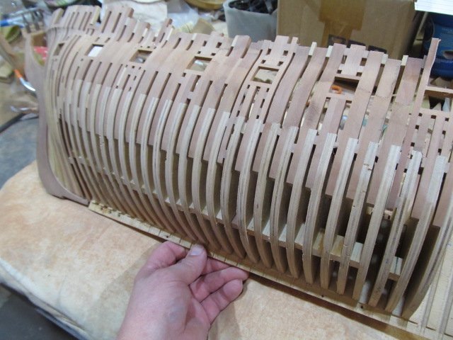
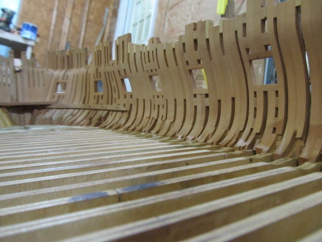
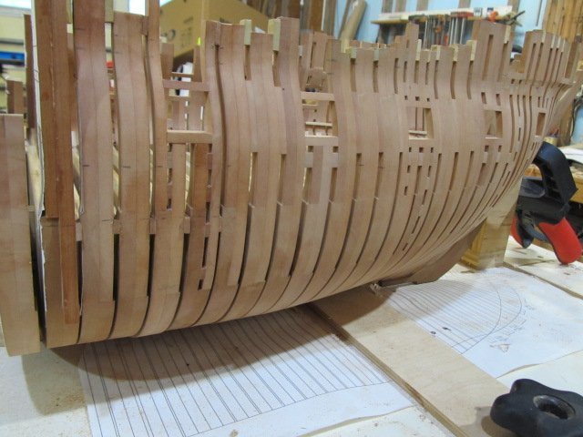
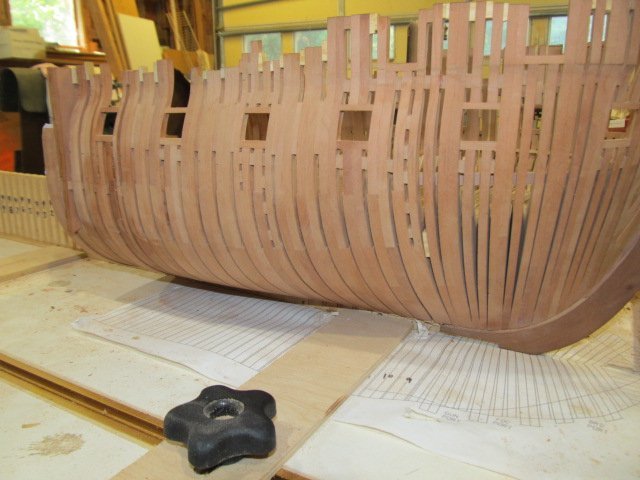
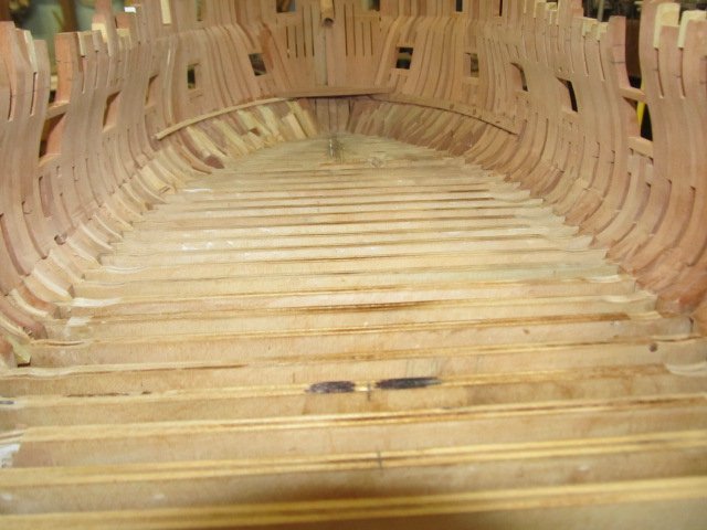
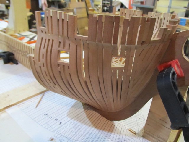
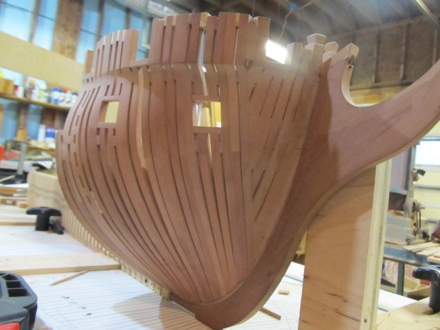
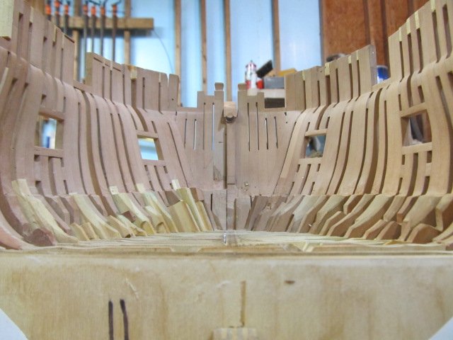
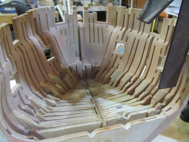
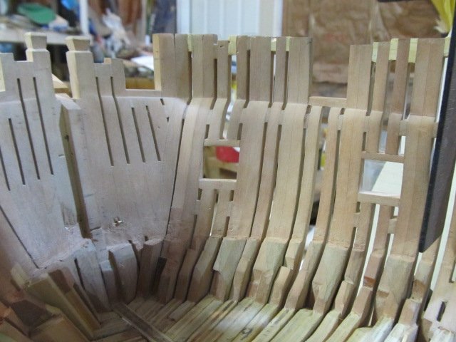
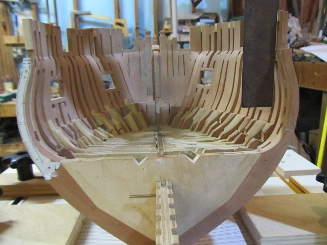
Hello everyone, I'm finally back with an update. It's been a very busy spring and summer, my apologies for not updating regularly. I have made more progress on Essex, I now have roughly 1/3 of the frames permanently glued in place. Fairing them is an ongoing process and won't be completed until all the frames are glued in place. At some point soon I'll be adding more of the "fake" gundeck clamps and beams. Anyway, a few pics and I'll try and post more as I get more frames added.

-
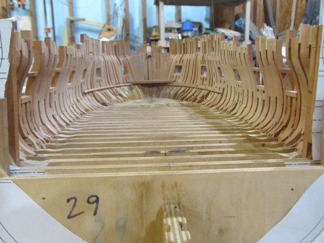
just a quick update, I'm still working on the square frames. I also added a deck clamp and fake deck hook. I say fake because neither this clamp or hook will be seen so I didn't spend the time to make prototypical ones. For the upper deck I will be framing in protypical fashion. fake deck clamp and hook for gun deck. I'll be adding fake beams as well to support the planking. I also finally started lofting the stern and eventually those pesky rear counter timbers... Hopefully all that I learned on the front cants will pay off here. And I'll soon have to decide on what stern arrangement I want to use since no historical data is available for Essex's stern in 1814. 3, 5, 7, 8 windows? Still don't know yet. Oh, and I received my new 3d printer so I need to play with that too! Thanks for the likes and thanks for looking in!
-
I knew there was a ship model in there somewhere.... And thanks for all the likes! Edit to add: I just ordered a 3d (resin based) printer. (Black Friday sale!!) First project(s) will be some 1/48 crew members for fun, then the Indian Figurehead. Down the road will be carvings n such for the stern - but that will be much later... And of course whatever else I can come up with. Probably carronades - or at least one for a mold master and cast the the rest. Not sure on that yet but I'm sure I can come up with plenty of things to try out!
-
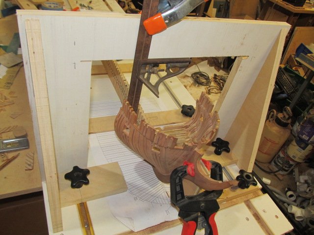
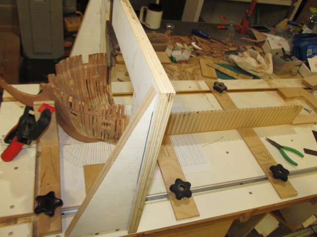
Welp, believe it or not the front cant frames are finished! Can't believe I'm actually at this moment! Also I finally built my overhead gantry, Ed Tosti style. As per my usual of over building everything, it's over built - but that's OK. It works and is square and solid. One area of concern I'm not happy about is the cant frames vs hawse hole placement. I drew and redrew that area and finally thought I'd reached my best compromise between the cants (and Hackett's design of them) and the hawse holes location using Baker and Fox's placement of them from 1809. After seeing the completed frames and roughly laying out where the holes will punch the cant frames I'm not happy at all. I will not however be going back and redoing the cants again. 3 times is enough. No one but the experts will know and at this point if I tear them out again I may loose my mojo and bail again. Don't want to do that. So, my shipyard and shipwrights will move on with the build. I'll show some pics later of the area of concern, right now I'm not going to dwell on it. Cant frames are 90% faired, they look pretty good now. Port sills are fair and a temporary deck clamp I installed looked good. Remember the port side will be planked over so if it looks a little rougher than starboard, it is 😉 Pics... And let me introduce my overbuilt Gantry Extreme 3000... You can also get a view of the build board I made - and more workshop clutter - seems that a theme with me LOL. Happy Thanksgiving everyone! catch you next time
-
Pulling up a chair, good luck Bob on another superb build!
-
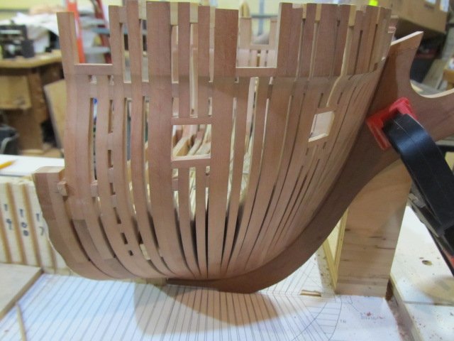
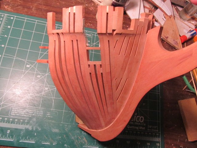
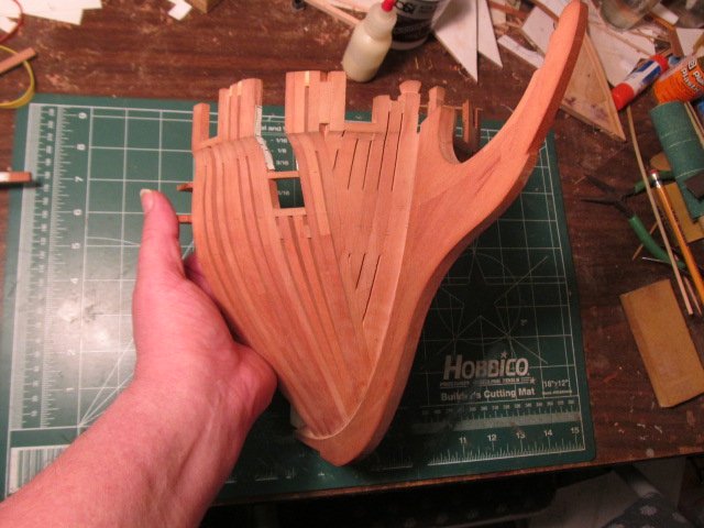
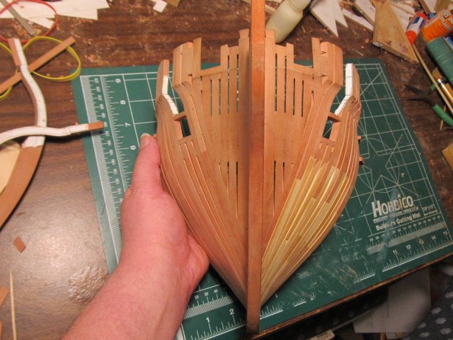
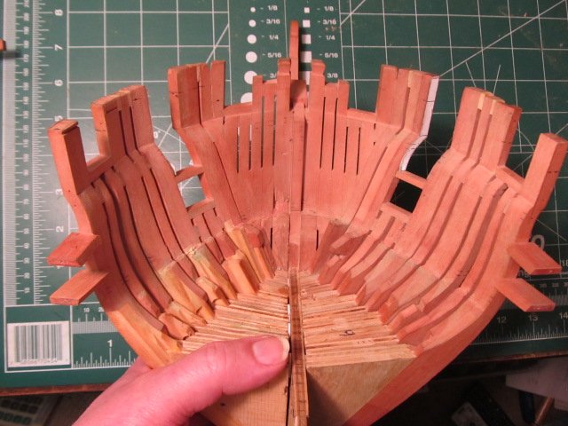
Still working on Cant frames, but only a few left to go. It's getting there. No major issues yet, I've been rough fairing as I go and so far no goofs on this version. Hopefully I'll finish them with no major mistakes. Lofting these was a real learning experience, my shipwright learning curve was huge AND making mistakes early on, but now finally my dwgs of the cants seem fairly accurate - I just need to make sure and leave a little excess material to fair. I still have to finish lofting the rear cants and then build them, I hope all the experience I gained on the front ones make the rear ones go smooth. But I get ahead of myself... Pics
-
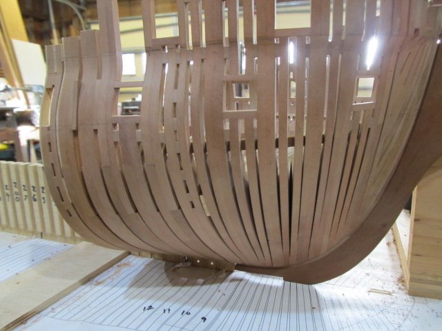
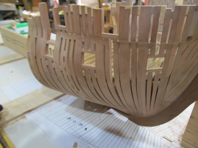
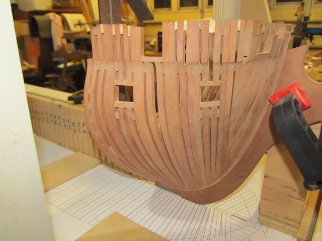
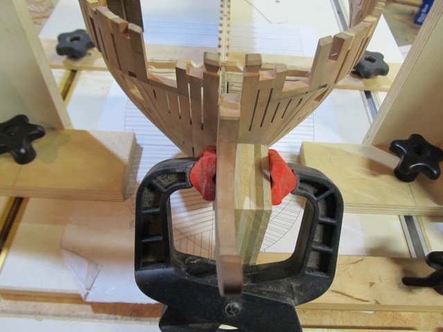
Well folks, here I am actually installing the cant frames for the last time. With glue. For real. Sorry for the humor, but this has taken so long to get here and so many setbacks - to be actually doing this is a major milestone! This is version three of the cant's. One version for issues with my lofting, another version for over aggressive sanding, and now this V.3 which is the final version. I've also had to remake a frame or 2 here and there for what I'll call *mistakes* and leave it at that. I'm getting there but still lots to go. Also framed my first complete gunport! The sheer looks nice and and the *fake* rabbet is now finally visible. There's still more fairing to do on the inside of what you see below. Using battens to fair is absolutely necessary IMO. All the bumps and dips show up that way. Anyway, pics. I'll post more when I have more frames glued in. PS - forgive the workbench situation - it's messy but it's mine.😁 Cheers and thanks for following along!
-
Scott, I'm trying DraftSight CAD program. I used TurboCad many years ago and didn't like it back then, not sure if I would now or not. DraftSight looks a lot like AutoCad (same shortcuts, layout etc) so I feel comfortable using it. I was able to get Solidworks Educator for free since I'm a member of the EAA (Experimental Aircraft Assoc) so that worked out well! Frolick, thanks for the dwgs. I actually have Chapelle's The History of American Sailing Navy so thanks for reminding me that is in there. Mike, I held of on the gammoning holes, I'll drill them at a later date with my small dremel - no big deal.
-
Frolick, are those plans something I can look at or are they copyrighted/protected somehow? I'd love the see them or get a copy.
-
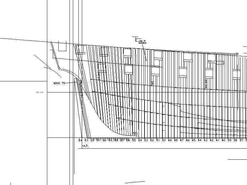
Mike, first off I admire your work and skills very much. I assume you're aware I'm lofting these plans myself from several references. To be honest I don't trust myself, lol. I've spent many hours drawing and redrawing the head of Essex. I'm at the point where I'm fairly certain (90%) that my head details are correct. BUT, if I run into a problem and I've drilled the gammoning holes in the wrong place, I'm screwed. Would you agree with my assessment or am I being TOO cautious? I haven't glued the cants on yet so I can still drill them on a drill press now very easily, if I want to. You can see below I want the gammoning holes in the middle of the cheeks area, and if for some reason I have errors in my lofting I don't find until I actually build the head, well, you can see where this is going. So that's my reasoning. But you have caused me to take pause and reconsider - damnit....😝
-
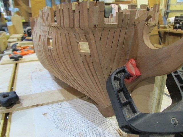
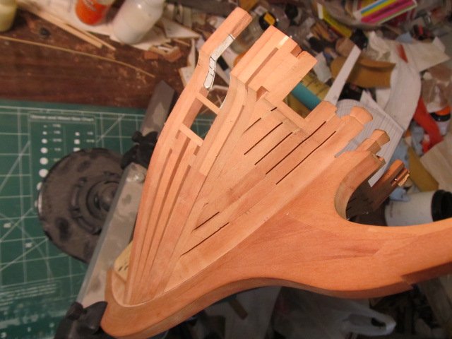
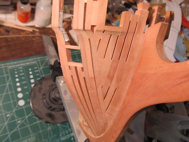
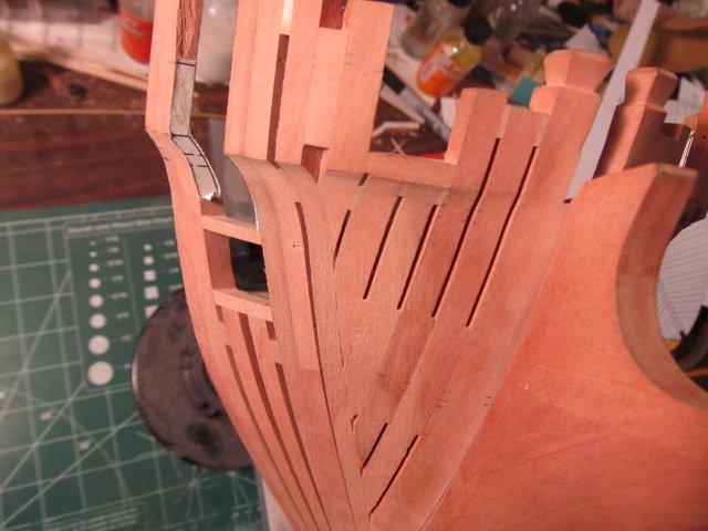
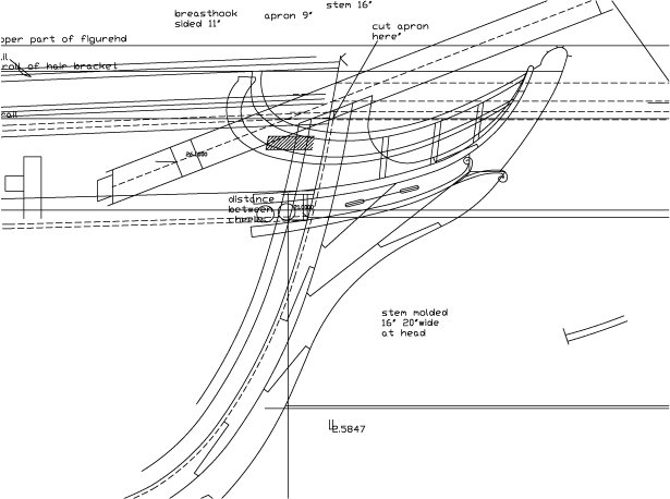
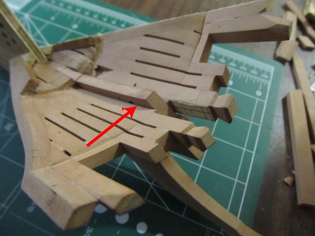
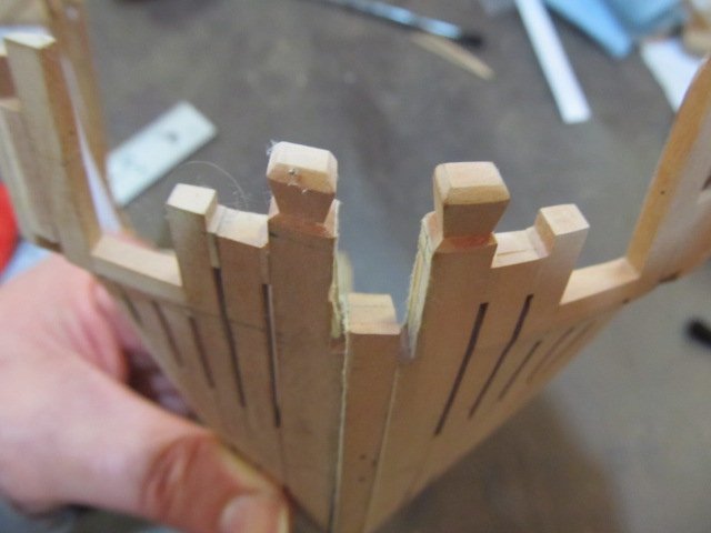
OK question for the experts. On the width, or depth, or siding (not sure of the correct term here) of the apron. I drew it and the bollards using various references. Josiah Fox's measurements are my defacto standard for this project so I'm sure I used his dimensions. My question is does the apron protrude out past the bollard timbers? I have drawn and built my version so it does. This means the deck clamps and inner planking will butt into the apron. I have seen this design on several references, but I think they were all English built ships. Did the Americans follow the same design? I would assume they did but I'm not sure. See the red arrows below for area in question. Keep in mind the apron, stem and bollards are not yet cut/drilled for the bowsprit. Any of you experts that know please chime in. I want to get this right if possible before I glue the cants on for good. (Frolick, do you know?)

-
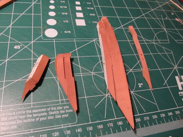
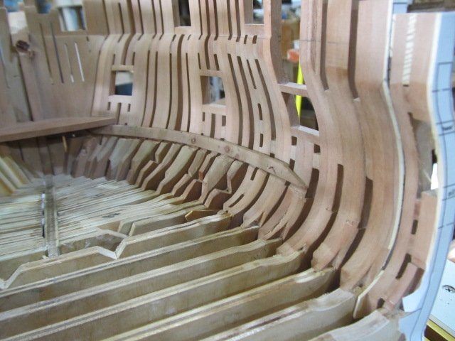
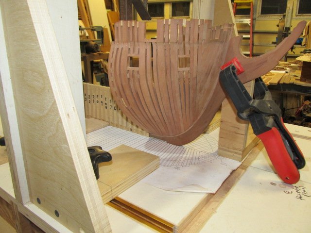
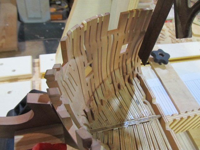
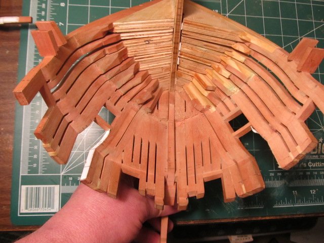
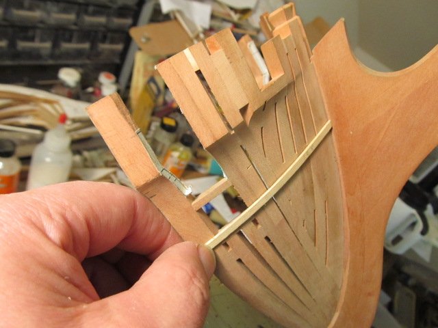
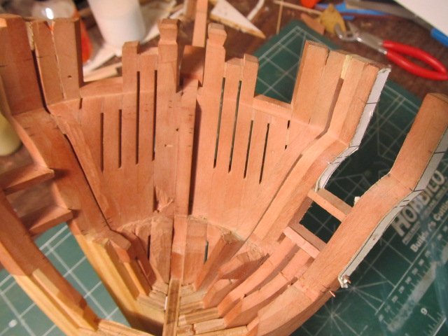
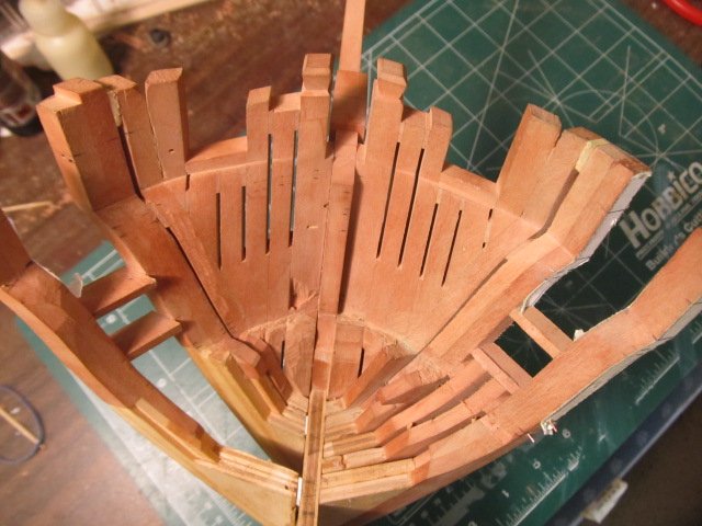
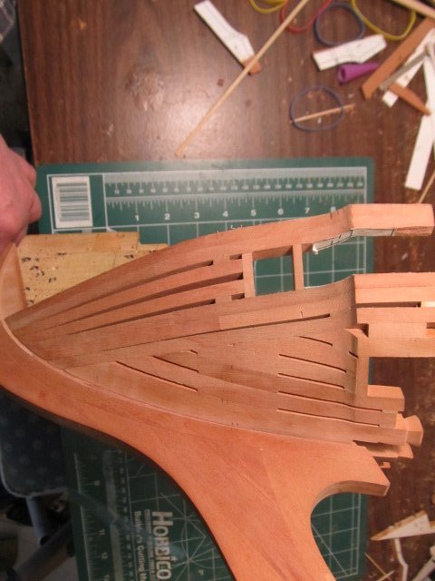
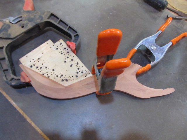
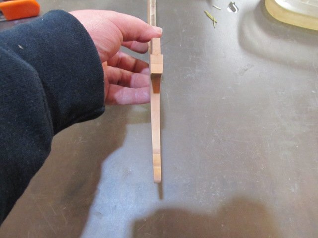
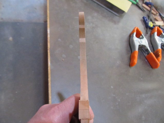
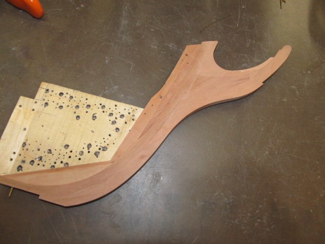
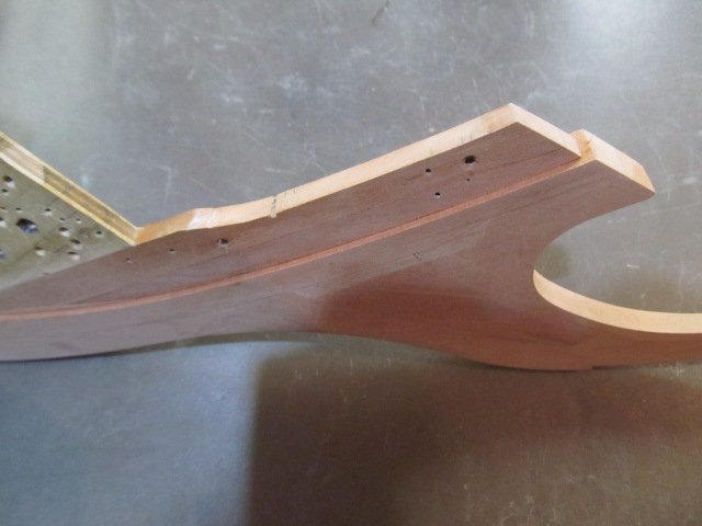
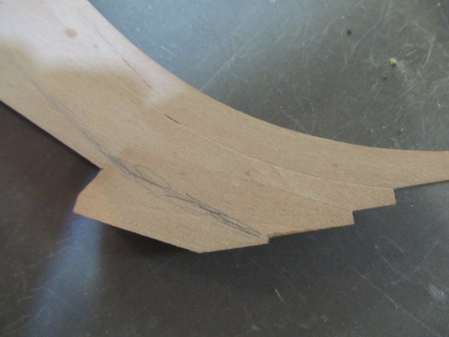
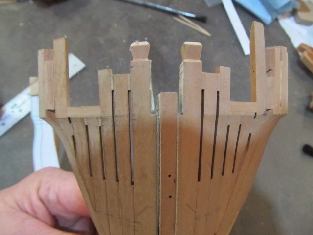
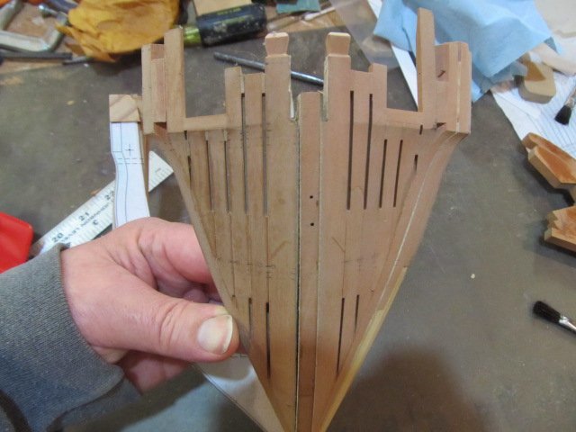
Thanks for all the replies and likes folks... So, after all the procrastination I suffered two years ago I decided "to hell with that and full steam ahead" or something like that - on the stem and cant frames. I taperd the stem, then glued it to the bulkhead/apron assembly. No going back now... There's pins in the bulkhead to hold the stem in alignment. I'm sure I showed those in an earlier pic somewhere. To taper the stem I used a large sanding block I use for auto bodywork. Made this job very easy. And here it is. I sure as heck hope I've built this correctly. You can now see the "fake" rabbet I mentioned somewhere back when describing how this assembly would work. I also shaped the apron to it's correct siding, or is it width - anyway how deep it is. I'm a tad concerned if I shaped it correctly, when I get the cant frame and bollards on I'll show what I'm referring to. The top of the apron/stem is not the final height or shape, I left plenty of extra to drill for the bowsprit later. I also chickened out on drilling the gammoning holes, I need to see more built before commit to those. Thanks as usual for looking in!
-
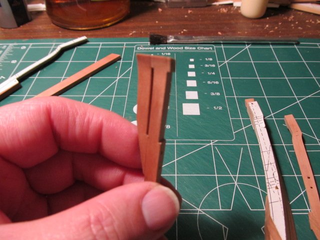
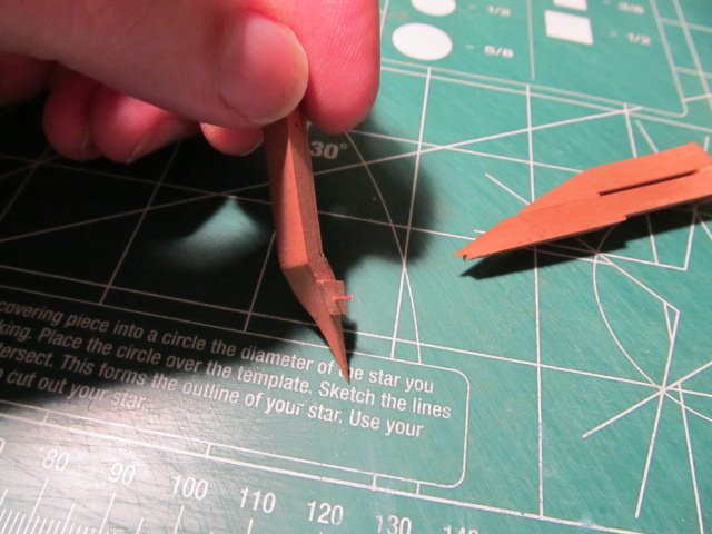
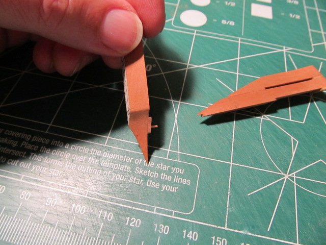
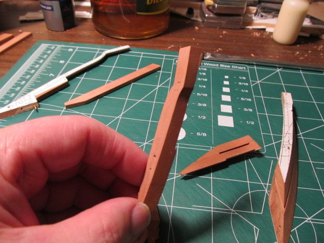
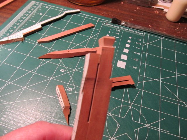
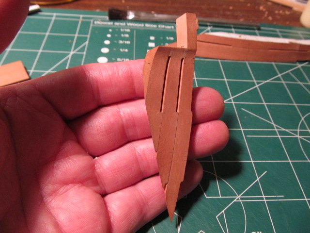
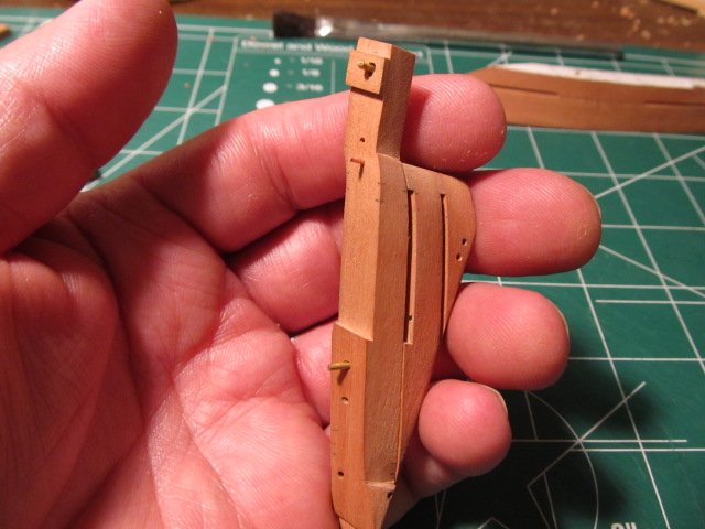
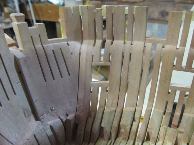
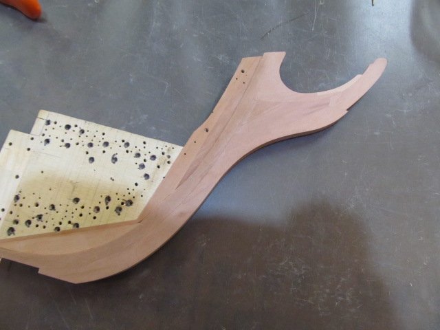
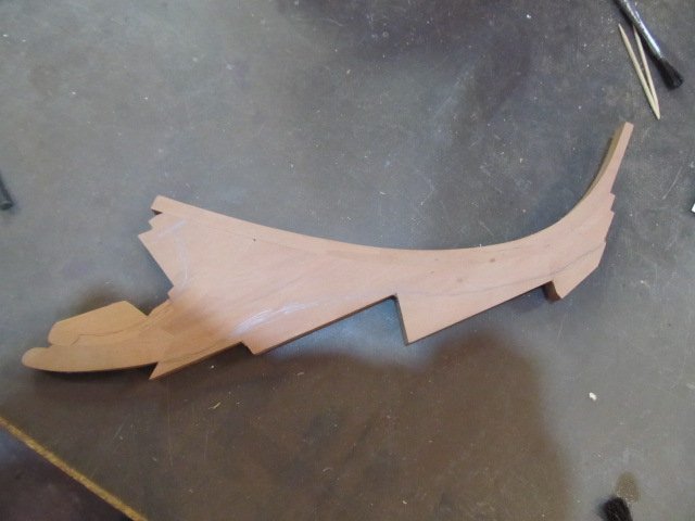
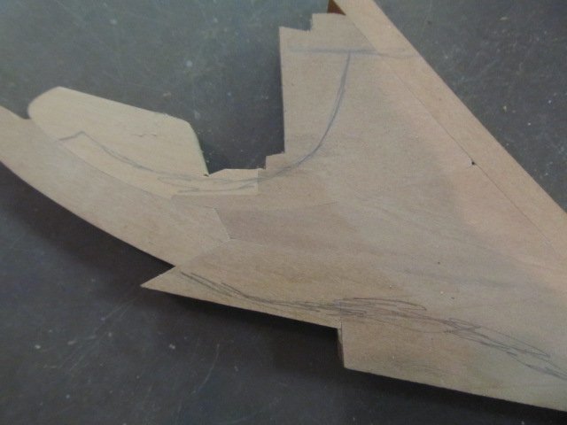
OK, a quick few pics to show where I'm at. I think I showed the stem previously, but here it is again - all glued up and ready to be cut to final shape. I need to drill the gammoning holes, I was hesitating doin g that cause once they're drilled that's that. So my procrastination on that may continue... I marked pencil lines on where the cut will be but it doesn't show up well. Hopefully the scarf joints show up when I apply finish. This pic will help show the shape and gammoning hole locations. I have the knightheads, hawse timbers and front 2 ports shaped. Once again I need to cut the hawse holes and I don't want to screw them up. I may drill a small pilot hole at the proper angle now that I can enlarge later, in case I goof up the location. Don't want to screw those up! Pardon the dust bunnies here, I just picked them up a took photos, lol. And have the internal side fared. This was a bear to do.... I still need to shaped the inner side of the stem post, double check my faring and the MAYBE I can finally glue this assembly together. That has been way overdue to get done... I also have to cut the stem post and stem for the bowsprit before gluing. Another operation I don't want to screw up!
-
Bob, I'm so sorry I haven't been around for 2 years, lol. It's not funny, but I'm laughing at myself anyway. I'm SO glad you're still here modelling. You, Frolic and Auggie were several of my biggest supporters around here and I'm so sorry I disappeared but life really got me down. But hey, now I'm back! Carry on mate, your model looks wonderful as usual!
-
ALL -- I need to sincerely apologize for not updating this topic in a timely manner the last couple years. The last two years have been filled with many life changes, deaths, depression/drama and so much I won't bore you with here. That however is no excuse for not posting an update or two. My apologies. Many thanks to Frolic for reaching out to me to see if I was still alive, lol. He has rekindled the interest I once had in this project and I will do my best to get back in the shop more often. I have made a little progress here and there and I need to take some pics to show where I'm at. Also, in a job move I lost my use of AutoCad and the large format printer/plotter I used, so I have to find replacement CAD software that's affordable and buy some type of large format printer. If anyone reading this has CAD recommendations please let me know. The biggest issue I have moving to another CAD program is 30yrs of AutoCad usage is burned in my brain so learning something else could be frustrating at first. On a positive note, 3d printers have gotten more affordable so I think I'll be investing in one of those at some point. 32 Cannons come to mind immediately, plus so much more little items for the model. Again I apologize and I'm glad to be back!
-
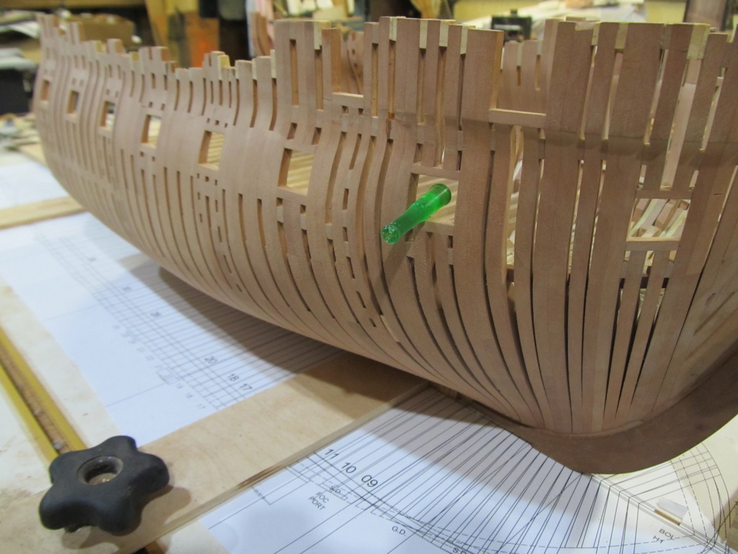
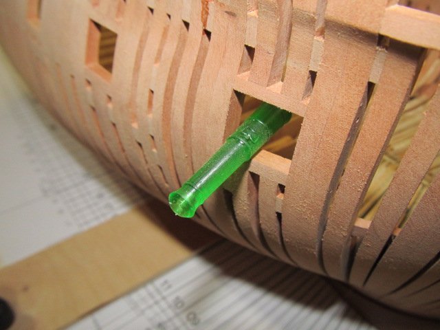
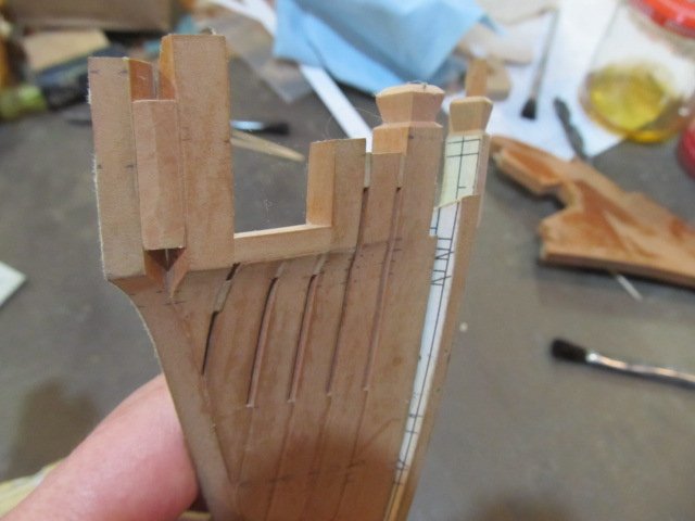
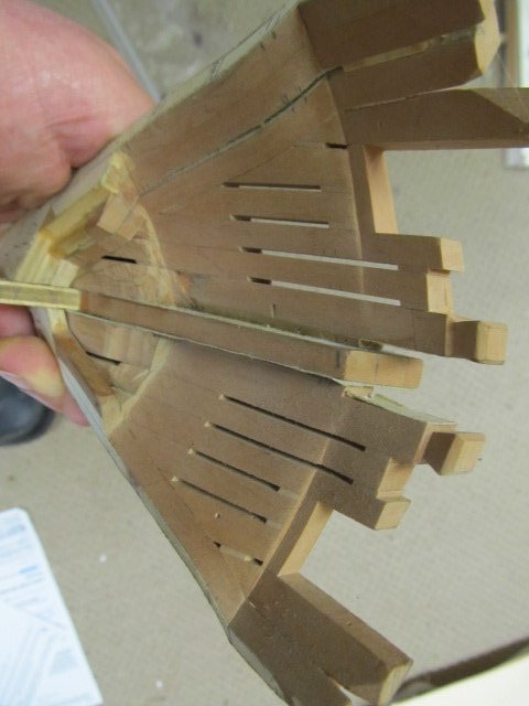
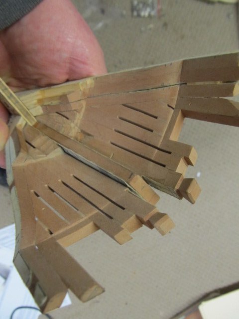
Shaping the hawse timbers is almost complete. I'm also framing out the foremost forecastle port and sill at this time. I'm using brass rod pins as I've been doing all along, and now also using pins made from copper wire as they are much smaller in diameter. These are .020" in diameter. If I choose to show bolts at some point ( I still haven't decided on that) I will use copper pins and coat them with liver of sulfur to turn them black. Thanks for looking and following along.