

Jeronimo
-
Posts
729 -
Joined
-
Last visited
Reputation Activity
-

 Jeronimo got a reaction from shipcarpenter in French 64 Gun Ship 1729 by Jeronimo - FINISHED
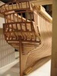
Bow part with the first twelve frames attached to the keel.
tracted inside and sanded.
Binnen-Vorsteven provisionally installed.
Karl
-
 Jeronimo got a reaction from GrandpaPhil in French 64 Gun Ship 1729 by Jeronimo - FINISHED
Hello Thomas,
where is the problem?
Karl
-
 Jeronimo reacted to Hubac's Historian in French 64 Gun Ship 1729 by Jeronimo - FINISHED
Das ist bedauerlich. Ich freue mich, dass Sie an Ihren Bemühungen festhalten.
-
 Jeronimo got a reaction from botra288 in French 64 Gun Ship 1729 by Jeronimo - FINISHED
Randsom wood, transom and frames 62 to 53 mounted.
Frames lined on the inside.
Schlempholz with its step fitted provisionally.
The images / drawings show the 74 GunShip by Jean Boudriot, Volume 1, as an example.
(Google Translator)
Randsomholz, Heckbalken sowie Spanten 62 bis 53 montiert.
Spanten innenseitig gestrakt.
Schlempholz mit seinen Stufen provisorisch eingepasst.
Die Bilder / Zeichnungen zeigen das 74 Kanonenschiff von Jean Boudriot, Volume 1, als Beispiel.
Karl
-
 Jeronimo got a reaction from giampieroricci in French 64 Gun Ship 1729 by Jeronimo - FINISHED
Bow part with the first twelve frames attached to the keel.
tracted inside and sanded.
Binnen-Vorsteven provisionally installed.
Karl
-
 Jeronimo got a reaction from KLarsen in French 64 Gun Ship 1729 by Jeronimo - FINISHED
Bow part with the first twelve frames attached to the keel.
tracted inside and sanded.
Binnen-Vorsteven provisionally installed.
Karl
-
Jeronimo reacted to archjofo in La Créole 1827 by archjofo - Scale 1/48 - French corvette
Fore studding sail booms / fore stays - Arc boutant de misaine
The lower studding sail booms were attached to the fore channels of the La Créole with a hinged fitting.
Source: Monograph on the La Créole by J. Boudriot
I made these lower studding sail booms together with the yards from pear wood (largest diameter 3 mm) some time ago. Likewise, the corresponding fittings with the eyelets for hooking in these booms were made and mounted on the front fore channels some time ago. Now these fittings had to be manufactured.
For the execution of these fittings I oriented myself at a corresponding illustration of the Paris model in the monograph. This design corresponds with drawings in the Atlas du Génie Maritime.
Source: Monograph on the La Créole by J. Boudriot
On the following picture collage, I have only shown the essential steps for the production of the fittings. I think the pictures are self-explanatory. The slots were milled. Unfortunately I did not take any pictures of this.
The next picture shows the blackened and mounted fittings.
And finally a picture of how the lower studding sail booms are hooked to the fore channels. These booms are secured to the front shrouds in the upper area by a lashing when not in use.
The next step will be the jackstays for the lower and topsail yards. There are still some details to be clarified.
So far I could not find much information in the relevant literature or on the internet.
Would be very grateful if one or the other could contribute something to this topic.
Continuation follows ...
-
Jeronimo reacted to archjofo in La Créole 1827 by archjofo - Scale 1/48 - French corvette
@Wintergreen
@wefalck
Thank you very much for your interest and appreciation.
Completion: Main yard - Studding sail boom iron - Cercle de bout-dehors de vergue
With the production of the studding sail boom irons for the main yard, this chapter can be brought to a close.
The first picture shows the already mounted studding sail boom irons of the main yard.
In the next pictures I have gathered all the yards that have been equipped with studding sail boom irons.
For the further equipment of the yards with blocks, footropes and jackstays, various details still have to be clarified.
More about that soon ...
-
 Jeronimo reacted to archjofo in La Créole 1827 by archjofo - Scale 1/48 - French corvette
@giampieroricci
@B-Ram
@albert
Hello,
Thank you for your interest and good approval, and all the others for the LIKES.
Here my further research results to this topic:
Continuation: Equipment of the yards - among other things Jackstage - Filière d`envergure.
In the meantime, I tried to get more information on this topic via contemporary technical literature. The search in the digital library of the French National Library was successful so far. In the work "Manuel du Manoeuvrier" I found this representation. This is an example of the yard arm of a topgallant yard, where the corresponding ropes are laid out in sequence.
Source: Manuel du Manoeuvrier, Agustin Challamel, Paris 1891, page 235
In this respect, I assume that this sequence can also be assumed for the other yards, because Petrejus also describes this arrangement in the book on the "Brigg Irene".
It is clear that for the lower yards a hanger or a strop with thimble for the yard tackle must still be considered. I tend to believe, as also described by Petrejus, that later it was also quite common to remove the yard tackle when not in use.
For the serving of the jackstay and footropes I show here the following:
For this, examples of the USS Constitution and the L'Hermione, showing served variants of footropes, and an unserved jackstay.
Source: Internet - USS Constitution
Source: Internet - L'Hermione
Whereas, to my knowledge, the jackstay on the L'Hermione cannot be historically correct in this way, but it probably serves as a safety line for the crew.
This illustration of a jackstay and footrope show unserved ropes. Here you can also see a strop with thimble and hooked yard tackle.
Source: Atlas du Génie maritime, annexe No. 1, detail Pl. 19
To be continued ...
-
Jeronimo reacted to Jimnclare in La Créole 1827 by archjofo - Scale 1/48 - French corvette
Every time I check in on Johann's mind-bendingly brilliant project I need to go and lie down in a darkened room with a bag of frozen peas on my head to stop my brain melting! The patience, skill, creativity and artistry is truly sublime.
-
Jeronimo reacted to Mic_Nao in L' Egyptienne 1799 by Mic_Nao - Scale 1/48 - 24-gun French frigate
Yes Dave, it's a scratch build.
-
Jeronimo reacted to druxey in French 64 Gun Ship 1729 by Jeronimo - FINISHED
Just catching up on your build. Very lovely so far.
-
 Jeronimo got a reaction from ccoyle in French 64 Gun Ship 1729 by Jeronimo - FINISHED
Bow part with the first twelve frames attached to the keel.
tracted inside and sanded.
Binnen-Vorsteven provisionally installed.
Karl
-
 Jeronimo got a reaction from Paryzek in French 64 Gun Ship 1729 by Jeronimo - FINISHED
Bow part with the first twelve frames attached to the keel.
tracted inside and sanded.
Binnen-Vorsteven provisionally installed.
Karl
-
 Jeronimo got a reaction from Hubac's Historian in French 64 Gun Ship 1729 by Jeronimo - FINISHED
Bow part with the first twelve frames attached to the keel.
tracted inside and sanded.
Binnen-Vorsteven provisionally installed.
Karl
-

 Jeronimo got a reaction from Brinkman in French 64 Gun Ship 1729 by Jeronimo - FINISHED
Bow, scale 1/48
Cant Frames mounted on frame 1.
Thank you very much for the comments,
please keep it up, criticism is also welcome and helps me.
Greetings
Karl
-
 Jeronimo got a reaction from Ainars in French 64 Gun Ship 1729 by Jeronimo - FINISHED
Randsom wood, transom and frames 62 to 53 mounted.
Frames lined on the inside.
Schlempholz with its step fitted provisionally.
The images / drawings show the 74 GunShip by Jean Boudriot, Volume 1, as an example.
(Google Translator)
Randsomholz, Heckbalken sowie Spanten 62 bis 53 montiert.
Spanten innenseitig gestrakt.
Schlempholz mit seinen Stufen provisorisch eingepasst.
Die Bilder / Zeichnungen zeigen das 74 Kanonenschiff von Jean Boudriot, Volume 1, als Beispiel.
Karl
-
Jeronimo got a reaction from botra288 in French 64 Gun Ship 1729 by Jeronimo - FINISHED
My mistake
Karl
-
Jeronimo got a reaction from Brinkman in French 64 Gun Ship 1729 by Jeronimo - FINISHED
52 Frames provisionally aligned on the keel, not yet straightened.
I will build the remaining frames including the transom separately
and only then place them on the keel.
After all this fixed on the keel, I will first straighten ans sand the inside.
Karl
(Google Translator)
-
Jeronimo got a reaction from GrandpaPhil in French 64 Gun Ship 1729 by Jeronimo - FINISHED
Bow part with the first twelve frames attached to the keel.
tracted inside and sanded.
Binnen-Vorsteven provisionally installed.
Karl
-
Jeronimo reacted to Ainars in French 64 Gun Ship 1729 by Jeronimo - FINISHED
Incredibly great work, Karl.
-
Jeronimo got a reaction from botra288 in French 64 Gun Ship 1729 by Jeronimo - FINISHED
Bow, scale 1/48
Cant Frames mounted on frame 1.
Thank you very much for the comments,
please keep it up, criticism is also welcome and helps me.
Greetings
Karl
-
 Jeronimo got a reaction from druxey in French 64 Gun Ship 1729 by Jeronimo - FINISHED
Bow part with the first twelve frames attached to the keel.
tracted inside and sanded.
Binnen-Vorsteven provisionally installed.
Karl
-
Jeronimo got a reaction from druxey in French 64 Gun Ship 1729 by Jeronimo - FINISHED
Bow, scale 1/48
Cant Frames mounted on frame 1.
Thank you very much for the comments,
please keep it up, criticism is also welcome and helps me.
Greetings
Karl
-
Jeronimo reacted to Siggi52 in HMS Tiger 1747 by Siggi52 - 1:48 - 60 gun ship from NMM plans
Hello,
so, it is done! The head is ready. 😃
The painter has to fix some things, because the man from the admiralty would come and inspect the work. He was very pleased and spend a beer for the crew 😮 Yes one beer 😕
For the next days the crew had some days free and after that, they have to cut the deck beams for the fore castle.