

Jeronimo
-
Posts
728 -
Joined
-
Last visited
Reputation Activity
-

 Jeronimo got a reaction from JerryGreening in LE BONHOMME RICHARD by Jeronimo - FINISHED
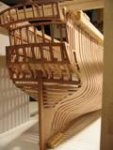
Hello,
assembly of iron knees and
A Hold
5 Shot- locker
6 Pump well
B Orlop-Deck
9 scuttle providing acces to the shot-locker
Karl
T e i l 32
-
 Jeronimo got a reaction from Hannerl in LE BONHOMME RICHARD by Jeronimo - FINISHED
Hello,
assembly of iron knees and
A Hold
5 Shot- locker
6 Pump well
B Orlop-Deck
9 scuttle providing acces to the shot-locker
Karl
T e i l 32
-
 Jeronimo got a reaction from Luca in LE BONHOMME RICHARD by Jeronimo - FINISHED
Hello,
assembly of iron knees and
A Hold
5 Shot- locker
6 Pump well
B Orlop-Deck
9 scuttle providing acces to the shot-locker
Karl
T e i l 32
-
 Jeronimo got a reaction from Jason in LE BONHOMME RICHARD by Jeronimo - FINISHED
Hello,
assembly of iron knees and
A Hold
5 Shot- locker
6 Pump well
B Orlop-Deck
9 scuttle providing acces to the shot-locker
Karl
T e i l 32
-
 Jeronimo got a reaction from Mirabell61 in LE BONHOMME RICHARD by Jeronimo - FINISHED
Hello,
assembly of iron knees and
A Hold
5 Shot- locker
6 Pump well
B Orlop-Deck
9 scuttle providing acces to the shot-locker
Karl
T e i l 32
-
 Jeronimo got a reaction from archjofo in LE BONHOMME RICHARD by Jeronimo - FINISHED
Hello,
assembly of iron knees and
A Hold
5 Shot- locker
6 Pump well
B Orlop-Deck
9 scuttle providing acces to the shot-locker
Karl
T e i l 32
-
 Jeronimo reacted to dvm27 in Speedwell 1752 by dvm27 (Greg Herbert) - FINISHED - Ketch Rigged Sloop
Bollard and hawse timbers continued...
-
Jeronimo reacted to dvm27 in Speedwell 1752 by dvm27 (Greg Herbert) - FINISHED - Ketch Rigged Sloop
Bollard and Hawse Timbers
Thanks, all for your kind comments. A bit of serendipity with regards to the crash - many of us are putting up more photos than the first version. The ease of posting them and lack of file size restrictions make it a breeze.
The bollard and hawse timbers are among the most challenging to make on the model. As well, they are the first timbers made after the keel, and the learning curve hasn't had a chance to kick in yet. So it's important to take your time getting them right and redo them if necessary (as Ed T. has also pointed out in his excellent log). The last little filler piece has no real pattern. It's just cut over-sized and "massaged" into place.
The last photo illustrates the rather diminutive size of Speedwell as compared to an earlier discarded attempt at my Swan class model. The sixth rate looks gigantic compared to Speedwell. Yet they wood both look like longboats compared to a third rate or larger!
-
Jeronimo reacted to dvm27 in Speedwell 1752 by dvm27 (Greg Herbert) - FINISHED - Ketch Rigged Sloop
Building Board, Keel Assembly, Stem, Deadwood, Knee of the Head, Mounting
-
Jeronimo reacted to dvm27 in Speedwell 1752 by dvm27 (Greg Herbert) - FINISHED - Ketch Rigged Sloop
At 1:48 scale, from counter timbers to the knee of the head she's a very sweet 22". Just for laughs, I've attached a rejected Swan bow for comparison. It makes our little sloop of war look huge doesn't it? So far only box has been used but holly wales are next with Fiebings leather dye to blacken.
-
Jeronimo reacted to dvm27 in Speedwell 1752 by dvm27 (Greg Herbert) - FINISHED - Ketch Rigged Sloop
Speedwell's framing has finally been completed. Note the various shifts and casts of the toptimbers as they frame the ports. There are many more of these on this vessel than on a Swan class ship and they can be challenging at times. My plan is to plank her from the ports up and rig her.
-
Jeronimo got a reaction from JerryGreening in LE BONHOMME RICHARD by Jeronimo - FINISHED
Hi friends,
first build the deck beams 1. Gun-Deck for the further interior in Orlop-Deck.
Karl
T e i l 31
-
Jeronimo got a reaction from JerryGreening in LE BONHOMME RICHARD by Jeronimo - FINISHED
Amendments of Cathead-rope
Karl
-
Jeronimo got a reaction from JerryGreening in LE BONHOMME RICHARD by Jeronimo - FINISHED
Hello friends.
There are three rider ( Kattspore ) in all reinforcing the hull.
The hooks and half-hooks of the mainmast step and the mast-step carlings.
These timbers are made up of a number of pieces because of their shape.
Karl
T e i l 30
-
Jeronimo got a reaction from Hannerl in LE BONHOMME RICHARD by Jeronimo - FINISHED
Hi friends,
first build the deck beams 1. Gun-Deck for the further interior in Orlop-Deck.
Karl
T e i l 31
-
Jeronimo reacted to Jim Lad in LE BONHOMME RICHARD by Jeronimo - FINISHED
Your very precise and beautiful work just keeps on coming, Karl!!
John
-
Jeronimo reacted to md1400cs in LE BONHOMME RICHARD by Jeronimo - FINISHED
Karl,
Love watching your building updates. A real pleasure for the eyes-superlative craftsmanship.
R/ Michael
-
 Jeronimo got a reaction from CaptainSteve in LE BONHOMME RICHARD by Jeronimo - FINISHED
Hi friends,
I try all the Pictures of my model "LE BONHOMME RICHARD 1779" to restore.
Regards Karl
-
Jeronimo reacted to kay in HMS Royal William by kay
Good evening in the MSW world,
thanks for the compliments, I am very happy that you like it.
As already seen the hull has been built into the shell construction. Robert Volk had described it in his book, and I tried it on the trunk of the ROYAL WILLIAM and am very satisfied. Between the frames have been glued pine wood strips of 5x10 mm. The strips I have had 1 mm above the frames protrude, and then I sanded the shape of the frames. So I got a very solid hull. The hull is also a little heavier, but that does not matter. The second planking pear wood used was 0.5 x 5 mm.
@ Nils: All carvings are made by myself. It takes a long time till I've finished, since I work with knives. For a ornamental pillar at the rear I have 20 minutes needed. Then there are some 80 pieces for many hours.
Here are some photos from the ROYAL WILLIAM arise. Tomorrow I will make again in the shipyard and take some photos of the carvings.
Regards Kay
-
Jeronimo reacted to kay in HMS Royal William by kay
HMS Royal William in 1719
Historical Background
The HMS Royal William in 1719 was the second ship of that name. The first HMS ROYAL WILLIAM was built in 1692 out of the 1670 HMS PRINCE forth. Rebuilt in this the extent of HMS PRINCE were retained, only the appearance has been significantly modernized. It was in honor of King William III. renamed HMS PRINCE in HMS ROYAL WILLIAM. The HMS ROYAL WILLIAM in 1692 was subjected to this Rebuilt in Chatham by shipwright Robert Lee.
William III. reigned from 1689 to 1702. He comes from the house of Oranien Nassau.
To make in England, he came through the „Glorious Revolution" 1688/89, at the Stuart King James II was deposed. William III. was married to Mary II Stuart. Mary II Stuart died on December 28, 1694th . After the death of William III. by Maria's sister, Anne Stuart power. Quenn Anne was the last British queen tables from the House of Stuart.
Anne reigned from 1702 to 1714. The English Parliament cleared the way for George I from the House of Hanover with the „Act of Settlement“. George I ruled Great Britain from 1714 to 1727. In the reign of George I., the second much Rebuilt HMS ROYAL WILLIAM. In 1719, she was subjected to this Rebuilt in Portsmouth by ship builder John Naish. You still kept the name HMS ROYAL WILLIAM. Rebuilt in 1756 during her next she was from a first rate to a seconde rate of 84 cannon built back. She was one of the ships of the Royal Navy with the longest period of service and was scrapped in 1813. Of the HMS ROYAL WILLIAM, there are three models in the NMM in London and one in Annapolis from the Rogers Collektion. Although the HMS ROYAL WILLIAM is one of the best documented ships of the Royal Navy, so there are very large differences in the models. In this I'll talk more about in the course of my building report.
My ROYAL WILLIAM is based on the plans of Euromodel. The keel and the frames are made of poplar plywood and the hull was built of pinewood. After a little bit of boxwood and pear only came to use. Now some pictures, I will soon, when I have more time, to write much more.
Regards Kay
I hope you understand my bad english, I will learn it here in the forum definitely better.
-
-
-
Jeronimo reacted to kay in HMS Royal William by kay
Hello folks,
Here are a few pictures that I have photographed today. The weather was perfect for photography. There currently I carve the adornments of the starboard side. And then I look forward to the figure head.
@ Sailor: thank you!
@ Dafi: I rush, I rush :-)
Regards Kay
-
Jeronimo got a reaction from Luca in LE BONHOMME RICHARD by Jeronimo - FINISHED
Hi friends,
first build the deck beams 1. Gun-Deck for the further interior in Orlop-Deck.
Karl
T e i l 31
-
Jeronimo got a reaction from Hannerl in LE BONHOMME RICHARD by Jeronimo - FINISHED
Hello friends.
There are three rider ( Kattspore ) in all reinforcing the hull.
The hooks and half-hooks of the mainmast step and the mast-step carlings.
These timbers are made up of a number of pieces because of their shape.
Karl
T e i l 30