

Erebus and Terror
-
Posts
410 -
Joined
-
Last visited
Content Type
Profiles
Forums
Gallery
Events
Posts posted by Erebus and Terror
-
-
This looking fantastic - beautiful choice of wood.
-
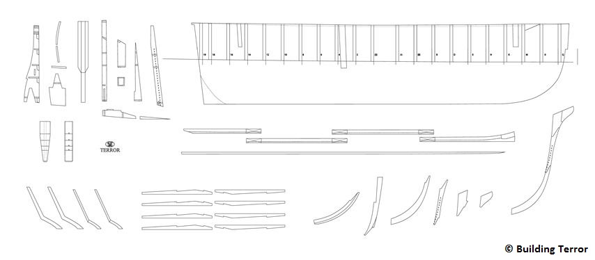
CONSTRUCTION PLANS
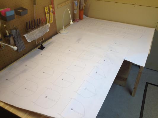
The construction plans laid out in my small workshop.
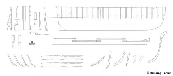
While I can never be certain that my plans are precisely correct, I believe, given the available historical sources, that they represent a reasonably accurate representation of HMS Terror as she was fitted for her final 1845 voyage. Certainly, much research remains to be completed on specific details (e.g. colour scheme, masting and rigging, hardware, name and cipher(?), etc.), but now that I’m satisfied with the accuracy of the ship’s general profile and dimensions, I can move to creating construction plans for a plank on bulkhead model.
I created the plans directly from the inboard profile and body plan, using a method similar to that outlined by Rich Brayshaw. The stern configuration from the sternpost to the rudder will be recreated just as it was designed in the Terror’s 1845 stern modification plan, and the keel, false keel, stempost, stemson, and knee will be constructed in a similar manner. The false keel structure will be made from 1/4 inch (6.35 mm) plywood, which matches the exact scale width of the sternpost and keel. The slots in the false keel descend to the load waterline, and will accommodate 21 bulkheads, corresponding to each station on the plan. While this might seem overkill for a 1:48 scale model of a small ship, it will give a very solid base for the planking, and I believe it will generally result in a more accurate model. You may notice that the height of the false keel doesn’t line up exactly with the inboard profile plans; this is because I modified it to account for the deck camber (derived from the 1839 Terror and Erebus cross section plan).
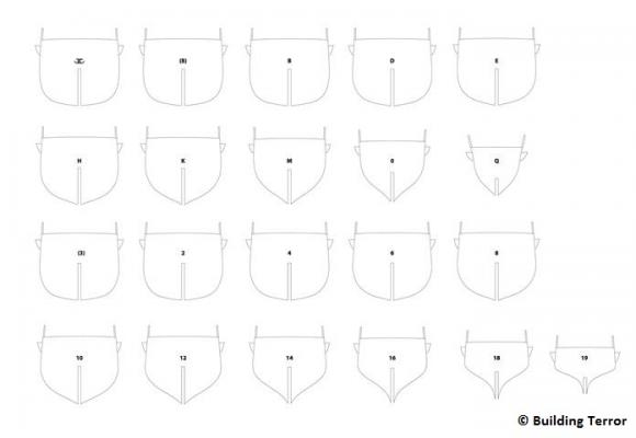
The bulkheads (which represent all the stations) may seem quite unusual to those who work with plank on bulkhead models. This is because each includes a precisely faired outline of the solid chock channels that surrounded the ship. The 1839 Terror and Erebus cross section plans show that the channels actually sat on the first layer of planking, and I considered recreating this, but quickly dismissed it. My reasoning is that, after a first layer of planking, it would be very difficult to line up the channels to create a perfectly symmetrical model. As a result, I’ll apply the first layer of planking around the channels (they will actually help me align it), then plank the channels, then apply the second layer of planking (recall that both the Terror and Erebus had double deck and hull planking). The bulkheads will be cut from 5mm plywood.
There is something very tangible to me about rolling out a freshly printed sheet; the plywood is now being pressed to remove any bends and twists; cutting starts this weekend!
-
Wow - how did I miss this until today? Wonderful precise work, Antony! I especially like the caulking.
This must be a real change of pace from your Corel cross section build. Thanks also for posting your PDF files, these are wonderful.
-
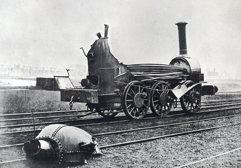
Further to Andy's great information, I thought it might be instructive to post this image.
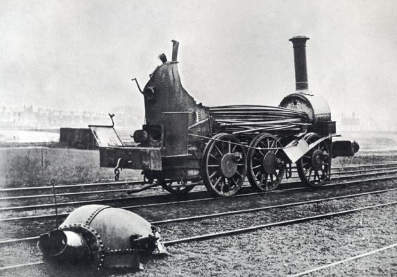
Clearly a boiler explosion on one of these ships would have been catastrophic, so their installation came at some risk. Considering that the engines had already been retired from the railway, and that fresh water would have been difficult to produce on these vessels (I assume salt water would have caused corrosion), I suspect the two engineers had many challenges.
-
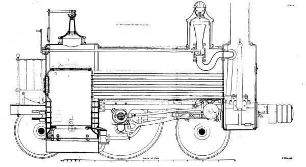
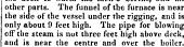
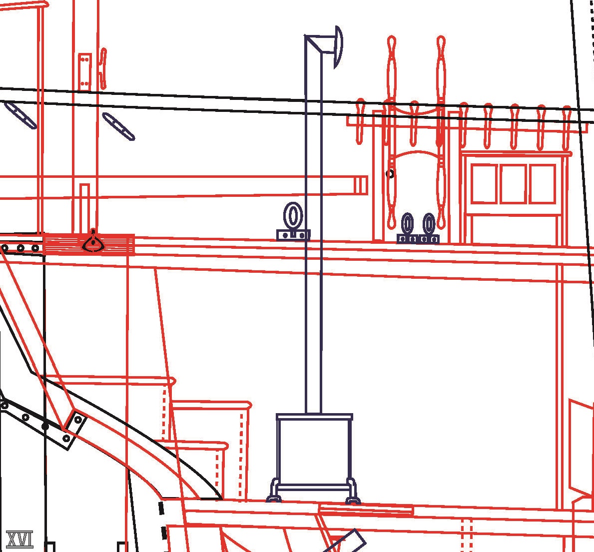
I see what you mean in your second photo. It is most likely hiding a steam safety valve (pop valve). This is a sprung valve that will lift if the boiler experiences too much pressure. I'm guessing the pipe was added to keep live steam from blasting directly into the engineer's and fireman's faces. Here's the inner workings:

In your sketch, live steam is collected in that funnel shaped pipe in the steam dome. At the base of that is the throttle valve. This is a saturated steam engine, so there is no superheater, the steam is then sent directly to the cylinders. The straight pipe coming up from the cylinders is the exhaust pipe. You can see how it narrows as it extends, but flares just before the base of the stack. By forcing the exhaust steam out at high speed (but not high pressure) it creates a vacuum in the smoke box (that's the compartment ahead of the boiler flues, the pipes leading from the firebox forward). The vacuum creates a draft drawing air from gratings under the fire bed, through the fire and forward through the boiler flues. The effect of this is creating a very hot fire. Hot fire equals more steam generated in a given amount of time equals greater speed/power from the cylinders. More modern locomotives used a small steam driven turbine to draw air when the locomotive was not being worked.
The other "dome" (with the lever) over the firebox is most likely part of a pump/injector system to get water into the boiler. Later locomotives do not admit cold water directly over the firebox. This is partly the reason so many early locomotives blew up. If the water in the boiler became too low and the crown sheet (top sheet) of the firebox became uncovered, a panicked injection of cold water would cause it to fracture. Steam at pressure would rupture the sheet, drastically causing the pressure in the boiler to drop, which in turn would cause any water remaining in the boiler to immediately flash into steam. Steam increases in volume 1600 times from water (at standard atmospheric pressure), considering a boiler of the size you've got, a volume of, say 1.5 to 2 tonnes, you can just imagine the effect.
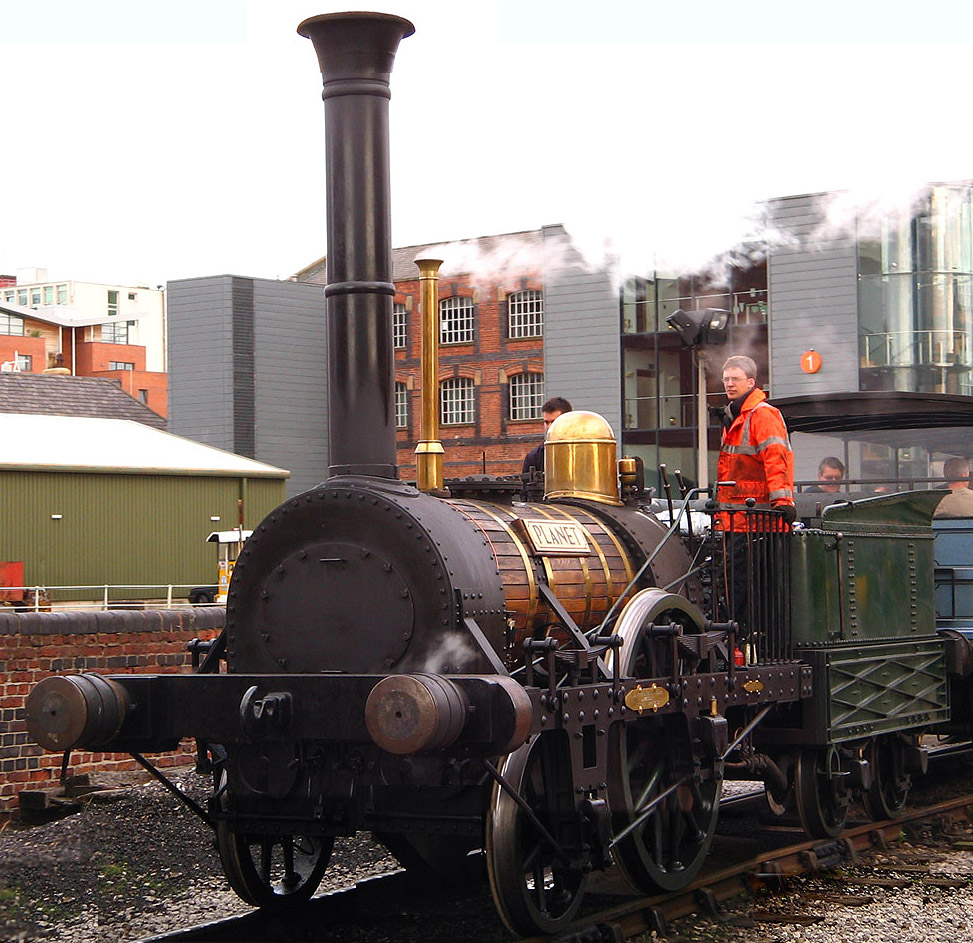
Another thought, is it possible your engine would have been of the "Planet" type (like your picture)? They where one of the earliest locomotives produced in large numbers, starting around 1830. Even by the late 1830s they were starting to be superseded by more improved designs, which would have made some of them available on the surplus market.
Andy
Hi Andy,
Fascinating stuff. I never thought about how dangerous the engines could actually be. Each ship only had one engineer. If one or both died (a good likelihood, given the mortality on the expedition), it would have been fairly dangerous for a novice to operate those machines. Adds another dimension to the expedition, for sure.
Regarding your thoughts on the "Planet" locomotive being the actual type used - that is a very good suggestion. In fact, the Planet locomotives have been assumed to be the engines utilized for many years. Peter Carney has done some good research on this (recently published), and he makes a convincing argument (to me) that they were either the Archimedes or Croydon types. Check out his blog if you are interested!
Thanks again for all of you information!
E&T
-
Fantastic research E&T. You have a better eye than I do and a lot more patience. When you are finally done you should try and write a book about your endeaver. I think many people would be interested.
David B
I really appreciate that, David.
I'm just happy to share on the boards and get such great feedback. I enjoy the research and everyone here has been very patient....
My main goal right now is to finally start cutting some wood!!!!
-
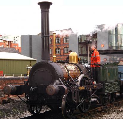
Also, here's an image of a reconstructed locomotive of a similar design - note the steam pipe. But if you have good alternative information, please let me know. I really want to make this model accurate, no matter how small the detail....
- Mike Y and themadchemist
-
 2
2
-
This steam fan in me just has to comment....
An exhaust steam pipe would not have some off that dome behind the chimney. Live steam is collected with an internal dry pipe and sent to the cylinders, whose exhaust is sent via a venturi tube and petticoat up the main chimney. This is how draft is also created in the firebox.
I could go on at length...but that might bore some people

Andy
Thanks for the input, Andy.
I'm attaching a cutaway image of the same engine. I'm no expert, but it seems to show a steam pipe coming from the cylinders. Am I wrong here? Also, the contemporary sources describe a separate steam pipe, so where was it coming from?
You won't bore me. Any input is appreciated!
-
-
Beautifully done - so precise!
-
Hi Druxey,
Thanks for your comment.
There is only a slight difference. Have a look near the outline of the ship's boat on both images; the hatch for the chimney is moved towards the center slightly, while the pipe for the steam is moved forward and away from the center (the old pipe was smaller and close to the a skylight near the center of the ship). The old steam pipe was smaller so no hatch - the new one was larger, so I gave it a hatch.
There really is only few inches difference for both.
Of course this will be a POB build, so you won't see that locomotive at all. All this work was simply to get the position of the chimney and steam pipe holes correct! Hours and hours of work, but there is no sense building it if it won't be accurate!
Cheers,
E&T
-
PROOFING THE PLANS: PART II – THE LOCOMOTIVE ENGINE
One of the major innovations of the 1845 expedition was the conversion of HMS Terror and Erebus to auxiliary steam power (Battersby and Carney 2011). On his blog, Peter Carney has documented his research on the locomotive engines used in this conversion; he later published his findings in the International Journal for the History of Engineering and Technology (Battersby and Carney 2011). To me, his research strongly indicates that the locomotive engines were not the Planet Type as has traditionally been assumed (e.g Cyriax 1997), but rather the Croydon and Archimedes engines built by G & J Rennie in 1838 and 1839.
Based on Carney’s research, I originally utilized a plan published in Brees (1840:133) which was labeled as the “Croydon” engine. However, in a recent email correspondence, Mr. Carney pointed out that this image was probably incorrectly attributed by Brees. The issue lies in the wheel arrangement and cylinder position. The image I based my locomotive plans on depicts a “0-4-2” engine with outside cylinders, while the Croydon was likely a “2-2-2” engine with inside cylinders (Bradley 1963; see also Carney’sblog). Mr. Carney believes the image I based my plans on probably depicted the “Hercules” engine, which was an assistant engine while the Croydon and Archimedes where passenger locomotives.
I always suspected there was something wrong with the locomotive I used in my original plans. If you look at my previous profile plans, the cylinders actually overlap the position of the spare rudder. Given that the modifications to the 1836 Terror plans show the exact position of the new engine room walls, this obviously could not have been the locomotive installed in 1845 (i.e. the locomotive was simply too big). Mr. Carney kindly pointed me to another image drawn by Brees (1840:306) which is unnamed, but which depicts a 2-2-2 locomotive with inside cylinders that was built by G & J Rennie – a good candidate for Croydon or Archimedes.
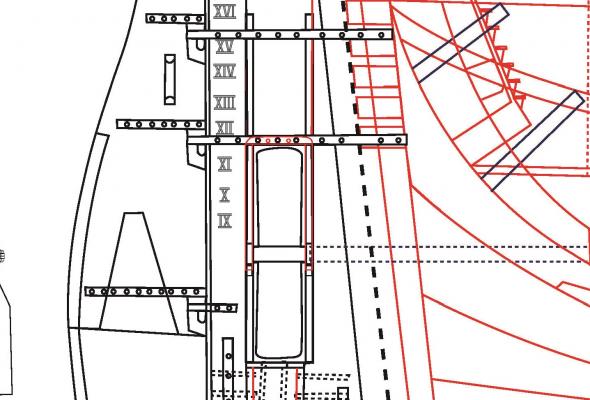
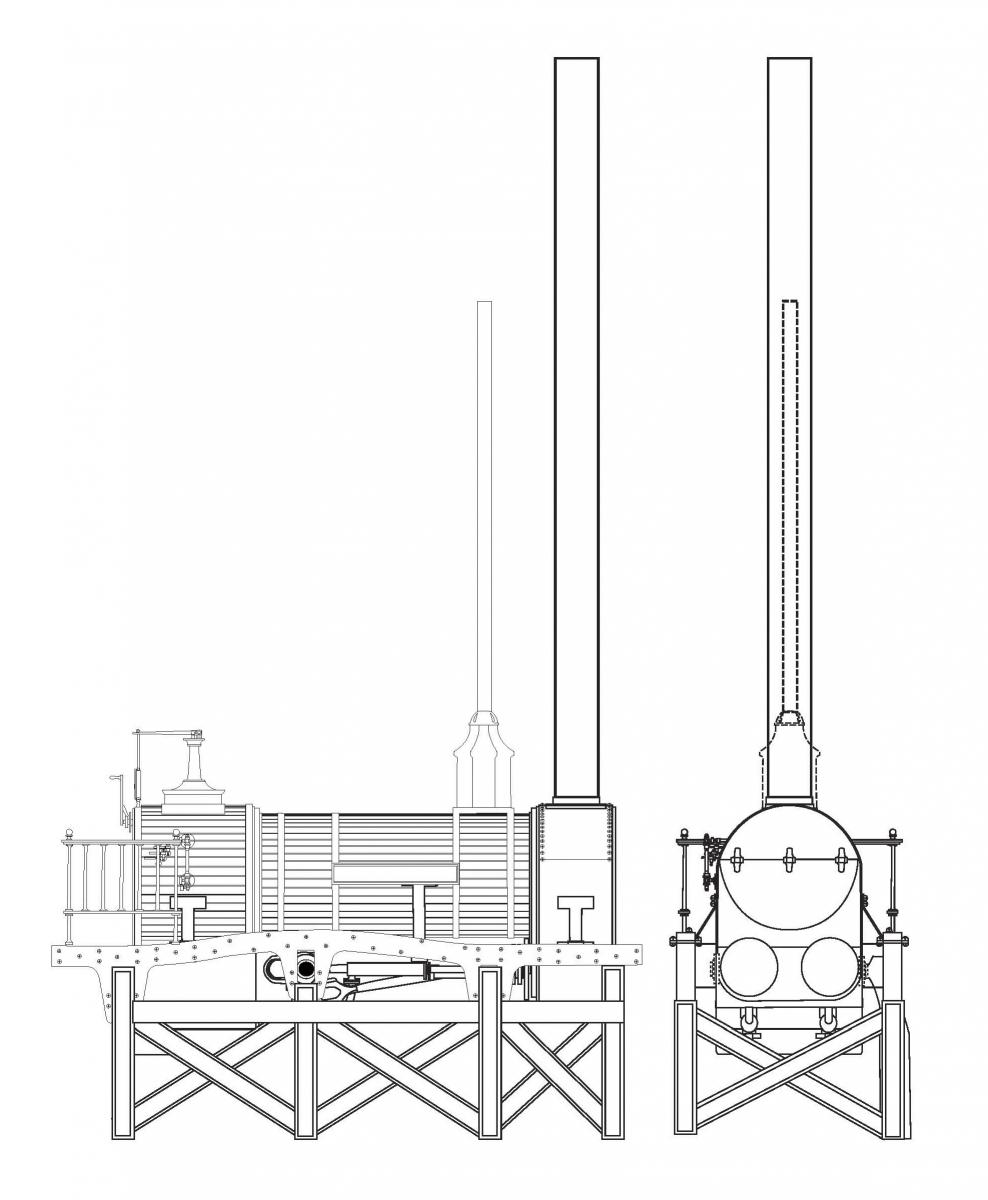
Using this new plan and an excellent set of drawings that Mr. Carney created and kindly provided (see his 3D reconstruction), I created my own scale plans of the locomotive. Using the dimensions from Bree’s (1840:14) original report, I scaled this new plan to exactly 1:48 and placed it in the proper position. As you can see, it fits perfectly, with just inches to spare on either side of the engine. To me, this exact spatial correspondence just adds credence to Carney’s theory that Archimedes or Croydon was the locomotive installed on HMS Terror.
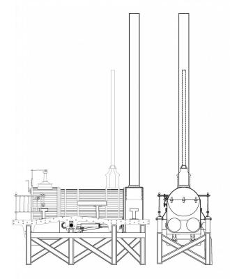
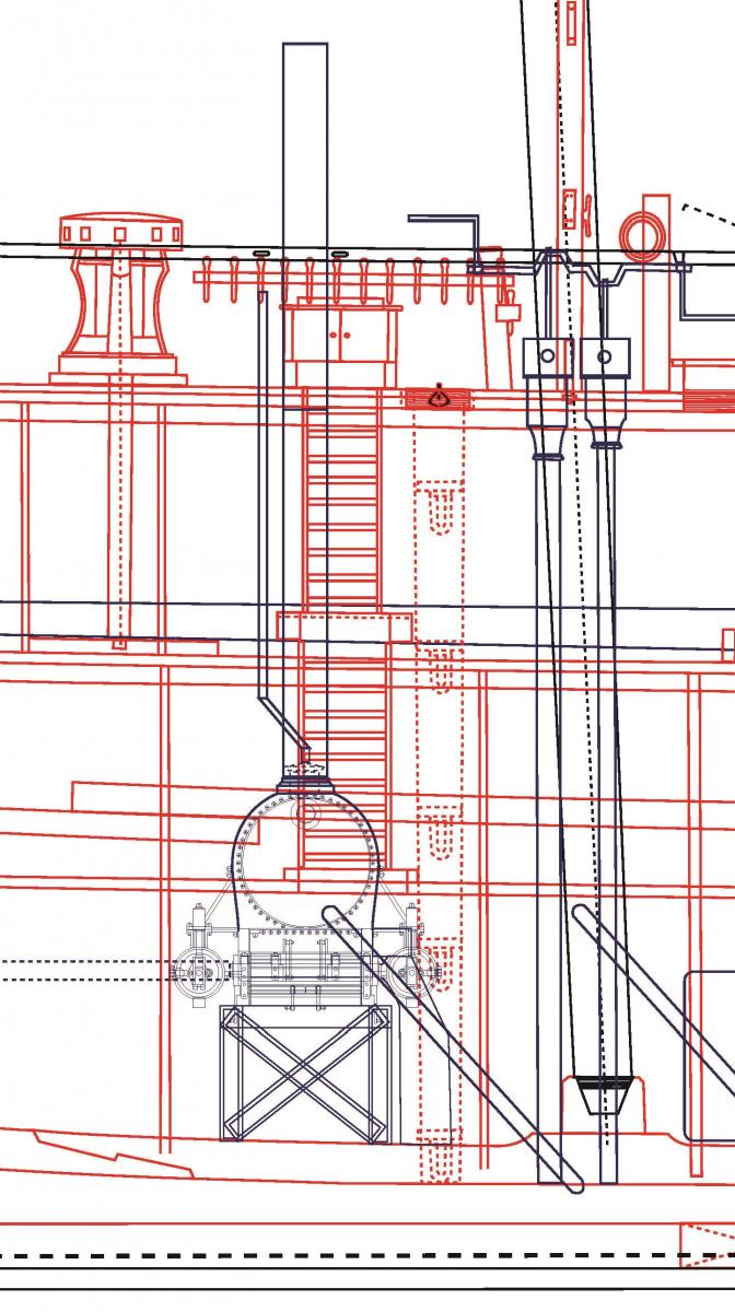
My new plans of the G & J Rennie engine, based on Brees (1840:306),
following the research of Peter Carney. The frame is speculative.
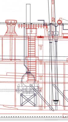
INCORRECT - My original plan using the Hercules (?) engine. Note
the overlap with the spare rudder.
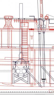
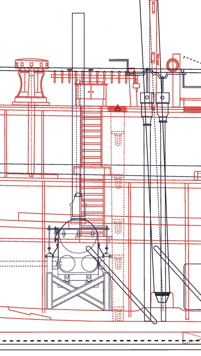
CORRECT? - The new engine in my updated plans.
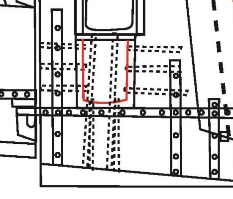
Because of the new locomotive engine, the position of the funnel and steam outlet changed significantly, and these are depicted on the new deck plans. Given that the locomotive was only used in calm conditions or to avoid beating, it is likely that the chimney and steam pipe were removable, to conserve space on the crowded deck (Battersby and Carney 2011:202). As a result, I believe a scuttle or hatch system was used when the chimney was not installed, and I based these on one shown in the 1836 Terror deck plans (I have been unable to determine what that 1836 hatch was originally used for – the furnace chimney was apparently installed at the fore hatchway).
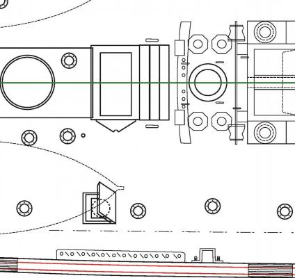
The positions of the chimney, steam pipe, and their hatches on my old plans.
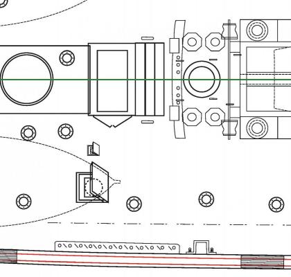
The positions of the chimney, steam pipe, and their hatches on my new plans.
Finally, I should note that on my plans the height of the engine’s chimney and steam pipe are based on the following contemporary description (which also accurately describes the location of the chimney and the steam pipe (Anonymous 1845):
* Note: Rather than post yet another set of updated plans, I’ve simply updated the plans on a previous blog post. The images have begun to be indexed on search engines and I don’t want to create confusion!
* For better images please see my blog!
References:
Anonymous,
1845 Literary Gazette Journal for the Year 1845. Robson, Levey, and Franklyn, London.
Battersby, William, and Carney, Peter
2011 Equipping HM Ships Erebus and Terror, 1845. International Journal for the History of Engineering & Technology 81(2):192-211.
Bradley, D.L.
1963 Locomotives of the South Eastern Railway. Solihull: Railway Correspondence and Travel Society (1):11–12.
Cyriax, Richard, J.
1997 Sir John Franklin's Last Arctic Expedition: The Franklin Expedition, A Chapter in the History of the Royal Navy. The Arctic Press, West Sussex.
- dnputnam, EdT and themadchemist
-
3
-
PROOFING THE PLANS: PART 1 - CONTEMPORARY IMAGES
Over the past several months I’ve received some great feedback on my research into HMS Terror from the model shipwrights on Model Ship World. However, before finalizing the construction sheets, I felt that that it was important to ask the opinion of some Franklin expedition historians.
A few weeks ago, I took the opportunity to contact two of the most knowledgeable experts on HMS Erebus and Terror, William Battersby and Peter Carney. Both maintain their own blogs and have published on the ships in peer-reviewed journals (Battersby and Carney 2011). Moreover, both are true gentlemen; they kindly took the time to read through my blog and offered some very useful advice on my plans.
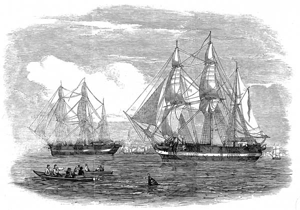
Mr. Battersby suggested that I look again at a drawing from the Illustrated London News (ILN) which depicts Franklin’s cabin on HMS Erebus. He pointed out that there appeared to be a cabin stove with a straight chimney on the extreme left of the image, which I did not include in my plans. The image seems reasonably accurate; the number and position of the windows and the shape and size of the stern lockers and superstructure matches the 1839 plans perfectly. As a result, I’ve modified my plans to include this stove; I based its dimensions and shape on what can be deduced from the image. The chimney for the stove is based on an 1839 image of a cabin stove available from the National Maritime Museum archive, and the height of the chimney is based on tables from Lavery (1987:291). Incidentally, the height of the chimneys for the ship’s stove and furnace are based on information in Lavery’s book as well.
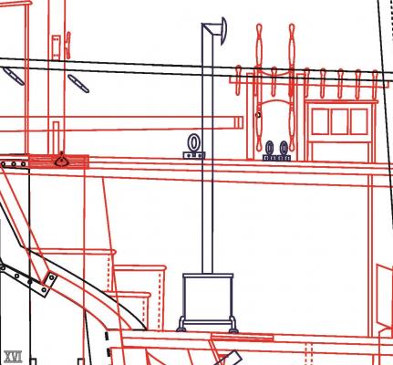
Cabin stove and chimney detail.
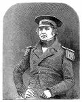
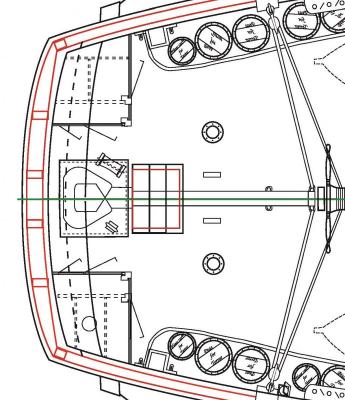
Mr. Battersby also reminded me that a (very early) 1845 daguerreotype image of one Franklin’s officers, Lt. Henry Le Vesconte, was taken on the deck of HMS Erebus. I’ve scrutinized it many times before and it’s a remarkable image which should be included in any thread about the ships. Le Vesconte is sitting on the starboard side of the Erebus (note the image is often shown backwards) next to the compass table in front of the mizzen mast. The photo confirms that the position and design of the skylight, mast, and wheel remain unchanged from the 1839 plans, and may also show part of a small deck house further aft on the starboard side (it appears to have a black door).
Mr. Carney also provided some extremely helpful insights. He pointed out that another image from the ILN shows two white deckhouses at the stern of both ships (note they also have black doors, just as in the Le Vesconte image). These were most likely water closets and signal lockers, and in my original plans I kept these quite low (almost the height of the bulwarks), based on an 1845 image of Erebus drawn by Owen Stanley. However the perspective used in his sketch probably foreshortens the height of the deckhouse and is not a reliable guide.

Following the ILN image, I modified the deckhouses to be the same height and size as the single deck house depicted in the 1839 plans. It is unknown if both were water closets or if one was a locker of some sort, so, in keeping with the original 1836 and 1839 plans, I am assuming that only one water closet was built for this voyage (only one water closet was used on Terror’s first two voyages, and the Terror had roughly the same crew compliment on all three polar voyages). I placed the water closet on the starboard side, following the suggestion of Battersby and Carney (2011:204) and based its design on the 1839 plans. I turned the other deckhouse into a locker for signal flags and other equipment and I admit its interior design is entirely speculative. Regardless, the model will have single black doors facing forward as is displayed on the ILN image (and which appears to be shown in the Le Vesconte daguerreotype). I should also note that both HMS Investigator and HMS Enterprise (1848 Franklin search vessels) shared many design similarities with the Franklin ships and both had twin deckhouses roughly the same size and shape as I have shown on my plans. In fact, both of their deck plans show the water closet on the starboard side of the vessel.
The new deckhouse profile, based on the 1839 plans.
Detail of stern water closet and signal lockers.
I should note that Peter Carney has also produced an excellent 3D model of James Fitzjames’ cabin, based on another contemporary image from the ILN. I did not include this structure in my plans as it was never depicted in any of the profile sheets (it is shown on the deck plans).
Finally, I should note that the daguerreotype discussed above isn’t the only one that might show part of the ships. Russell Potter, another Franklin blogger, has written some very interesting posts about the reflections in the highly polished caps of the Royal Navy officers, which show the rigging and perhaps the position of one of the ship’s boats.
* Note: Rather than post yet another set of updated plans, I’ve simply updated the plans on the previous post. The images have begun to be indexed on search engines and I don’t want to create confusion!
References:
Battersby, William, and Carney, Peter
2011 Equipping HM Ships Erebus and Terror, 1845. International Journal for the History of Engineering & Technology 81(2):192-211.
Lavery, Brian
1987 The Arming and Fitting of English Ships of War, 1600-1815. Conway Maritime Press, London.
- themadchemist, dnputnam, mtaylor and 2 others
-
5
-
Beautiful work! Love this ship.
-
Mark: the prop could be uncoupled from the shaft before it was raised, in the vertical position.
Thanks Druxey. I'm assuming a slip fit type of coupling? I think I'll Google for a bit as these little things raise my ears and poke my curiousity button.
Hi Mark,
Druxey is correct. The prop shaft was simply extended when the propeller was shipped. I'm not certain what sort of coupling was used on Terror (it's not discussed in any literature that I could find), but Battersby and Carney suggest it might have been a "telescoping coupling" similar to that installed on HMS Ajax in 1846. You may want to consult Bourne's A Treatise on the Screw Propeller (1855). The document has several very detailed drawings of raising propeller frames and couplings. None of these perfectly matches the configuration shown in the plans of HMS Terror, but several are very similar (see here and here). The book is available for free on Google Books.
Thanks for the interest - I always enjoy these questions because they force me to think of things I haven't thought of before (i.e. how do I model the shaft and coupling?). Also, the original plans, which I have replicated almost precisely in my plans (warts and all), clearly simplify many details. I'll be using sources like Bourne's to add all those little details when I build the model. Should I transfer those details to the plans? I probably won't - I want them to be clearly based on the originals, even if I'm altering them to create the vessel as fitted in 1845. But I'll discuss them here, of course!
Cheers,
E&T
-
Joss, I'm learning a lot from your research and I'm impressed with your work. Will look forward to more posts!
-
-
HMS TERROR PLANS – UPDATED!!
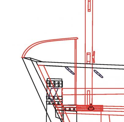
As discussed in the previous post, here are the updated (hopefully complete?) plans for HMS Terror. Note that the Upper Deck Plan has been modified to include the accurate width of the propeller well, based on information gleaned from the engineer’s model. Also, I noticed that the model showed a narrow lip surrounding three sides of the well for the scuttle to rest on, so that has been included in the plans as well.
- druxey, themadchemist, mtaylor and 2 others
-
5
-
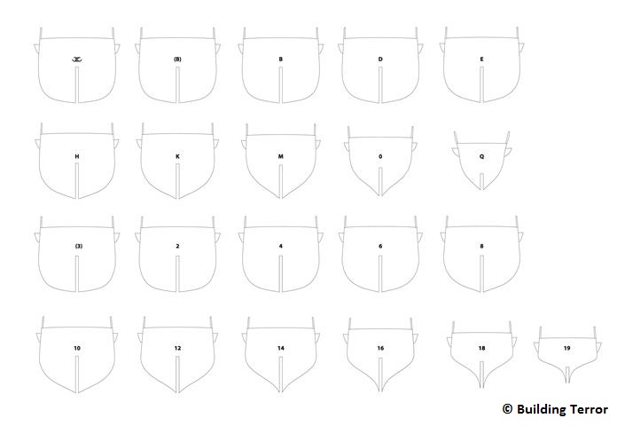
Over the past couple of weeks I’ve been designing construction plans for my model (I hope to begin cutting wood next week). As I worked on individual stern components, I began to notice possible errors in my plans. Specifically, the original 1845 stern sheet (and the annotations on the 1836 sheet), on which my plans are based, only exist in profile and therefore don’t depicted all the necessary cross-sectional modifications to the stern that were required. The problem lies exclusively in the well that was constructed to ship and unship the auxiliary screw propeller. If the rudder post (also known as the “false sternpost” or “after sternpost”) was the same width as the sternpost depicted in Terror’s original 1813 plans, there simply would not be enough space for the propeller well positioned directly in front of it. I strongly suspected that the rudder post was thicker than I originally depicted in the body plan (and thicker than the keel), but there were no historical plans that confirmed this. Fortunately, an engineering model of the modified stern was produced for the Erebus and Terror ca. 1845.
As can be seen on the model, the upper part of the rudder post was indeed widened, apparently by adding two large bolsters on either side; it then tapered abruptly at the opening for the propeller (likely to prevent drag). The added width on the upper part of the rudder post provided the necessary space for the propeller well and I’ve now changed my body plan to reflect this. However, in scrutinizing the stern plans and annotations to solve the width problem, I also noticed some faint modifications that I missed in my initial tracing of the plans.
First, the opening for the propeller well apparently included two separate iron fittings which were bolted to the rudder post and the sternpost, respectively. Each fitting appears to have had a groove which accepted a smaller rectangular metal frame which held the propeller (e.g. Battersby and Carney 2011: 204; 208). Guided by the metal grooves, the propeller frame could be raised or lowered into position using standard ship’s tackle. A contemporary example of exactly this sort of removable propeller system is preserved in a model at the National Maritime Museum in Greenwich (see here and here for similar designs).
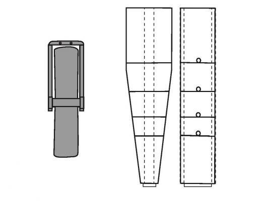
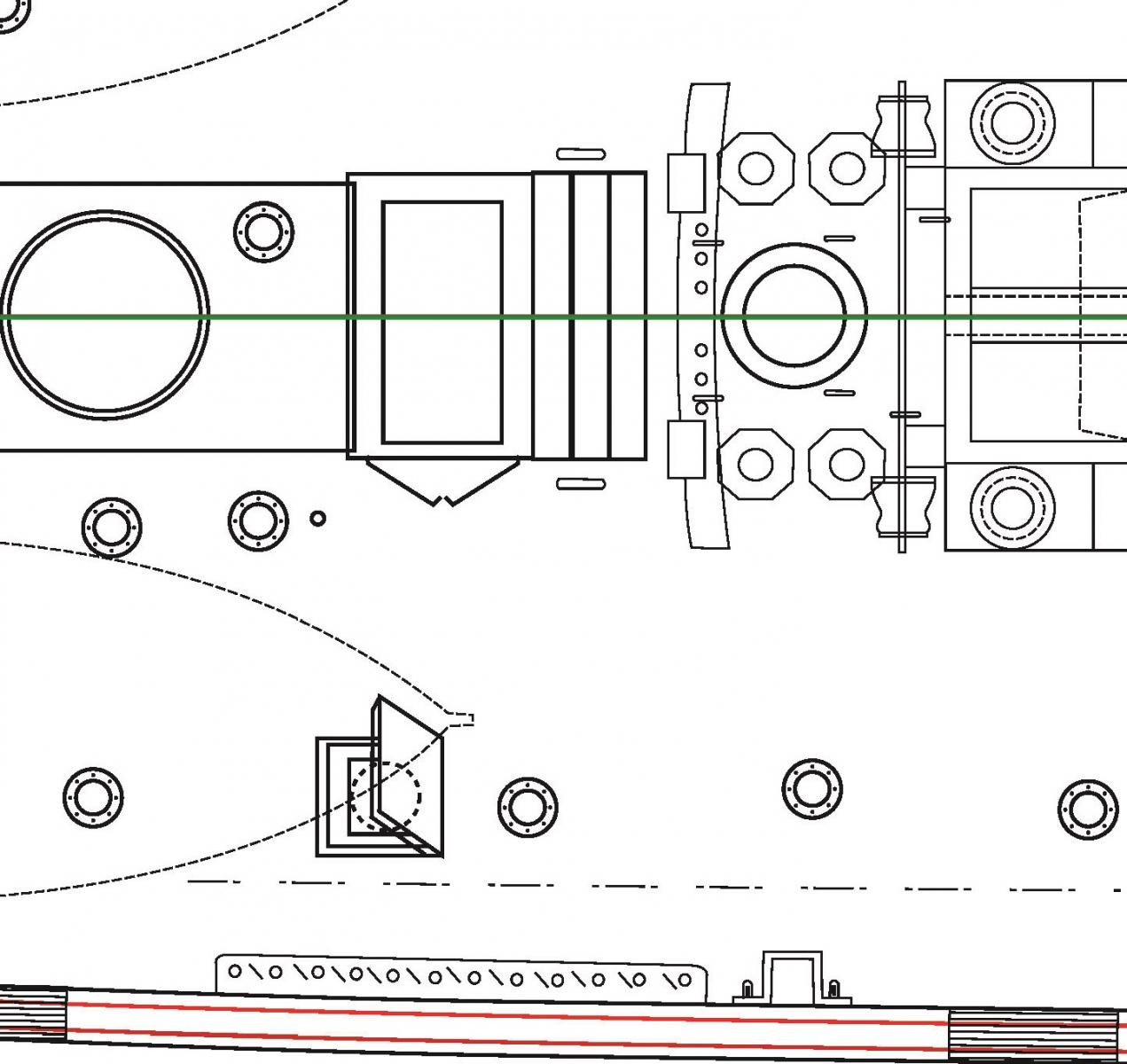
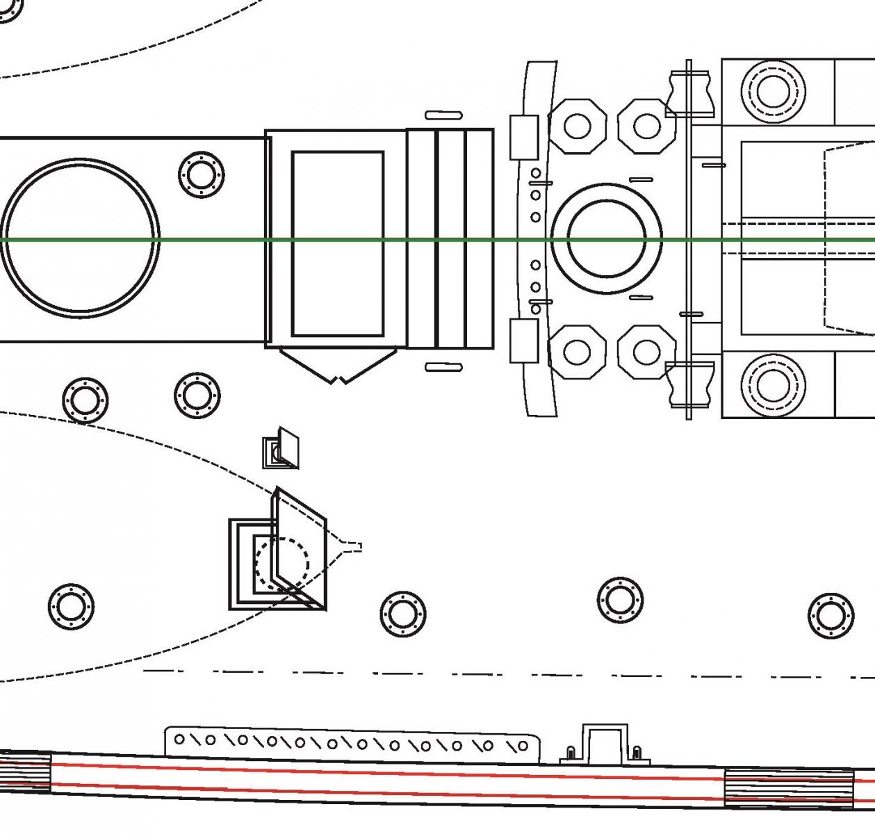
My reconstruction of the propeller frame and chock system (profile and cross section).
The series of chocks were used to strengthen and protect the stern when the propeller was unshipped
The propeller frame as it would have been installed
Second, it appears that a unique u-shaped iron fitting, the same length as the propeller well, was used to secure the sternpost, keel, and rudder post to each other. Two or three large bolts secured a separate timber to each of the three faces of the fitting, effectively creating one solid structure. I suspect that this was a midline fitting which was protected and covered by a large fitted wooden chock, which itself was bolted to the surrounding wood, probably with as many as four bolts. Why this unique fitting was necessary has not been described in the historic literature, but is seems certain it was used to increase the strength of the sternpost near the keel (recall that Back’s voyage proved how vulnerable an unmodified stern could be to pack ice). How the ship’s stern timbers were attached to this structure is also not described, but it seems logical that the rudder post and sternpost would have been bolted to the two central stern timbers, with which the widened sternpost would have been contiguous. Contemporary models show that a sturdy rectangular frame enclosed similar contemporary propeller wells, and the sternpost and rudder post were also bolted to this frame.
The "U" shaped bracket and series of bolts used to attach the rudder post and sternpost to each other and the keel.
References:
Battersby, William, and Carney, Peter
2011 Equipping HM Ships Erebus and Terror, 1845. International Journal for the History of Engineering & Technology 81(2):192-211.
-
Thanks very much for the kind comments and insights! Chris Ware's book is indeed fantastic and has a huge amount of information on bomb vessels.
-
Thanks for the interesting comment, Druxey - I'm really interested in this topic.
As you say, there are a number of plans with diagonal planking at the NMM, such as the Agincourt (1817), Britannia (1820), Hamadryad (1823), Cambridge (1815), and Unicorn (1824). These all seem to show planking that cants in towards the centerline when moving forward, not out from the centerline when moving forward. The only vessels I have seen with planking canting outwards are polar exploration vessels (e.g. Erebus, Terror, and Investigator). I know diagonal planking was meant to increase strength (so Seppings' involvement is a very intriguing proposition), and I'm wondering if the difference in cant is significant (i.e. did it provide even more strength than the reverse)?
Are you aware of any other vessels with planking that cants outwards from the centerline towards the bulwarks when moving forward?
Thanks again for the interesting comment!
-
HMS TERROR, 1845, UPPER DECK PLAN (AS FITTED)
The last technical plan required for HMS Terror is the upper deck, which I have finally completed.
Please note: This plan has been updated - please consult my later posts.
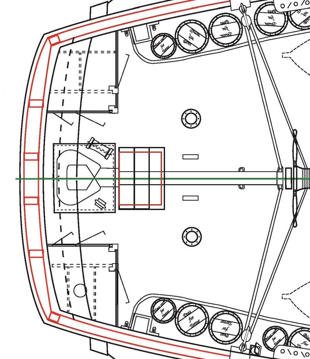
The original 1836 and 1839 deck plans for HMS Terror show the outlines of the ship with planking installed. Therefore, on my plans, I have included the outline of the frames as well as the planking to better facilitate construction. Like the original plans, the position of the solid chock channels accounts for tumblehome. Because the 1839 plans depict HMS Erebus, my plans are based on the 1836 upper deck plans for HMS Terror, but the deck furniture is the same type and style as depicted on the 1839 sheets (see previous posts for rationale). Similar to the profile plans, the position of the deck furniture is based on the 1836 sheets.
The most substantial modifications to the plans are at the stern - to accommodate the new position of the rudder and the well for the screw propeller. As a result, the central structure on the stern containing the cistern, color boxes, and water closet was removed from these plans (presumably these were moved to the position of one of the chicken coops). These modifications are also depicted in a contemporary image of the Erebus drawn by Owen Stanley, which shows two large structures on either side of the vessel at the stern.
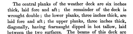
The deck planking on the vessels was unusual and was not depicted in any contemporary plans. Rice (Ross 1847), the shipwright responsible for the refitting, described them in detail:
A contemporary model of HMS Erebus displays that the upper layer of deck planking angled outwards and forwards from the central planks towards the bulwarks. This style was also used for the upper deck of HMS Investigator, which searched for the Franklin vessels on two voyages between 1848-1853. Investigator’s upper deck plan shows that the planking was placed on an angle about 45 degrees from the centerline. On my plans, the width of the central planks is based on the 1839 midships cross section, but the width of outer planks is not described in any contemporary sources and required more research. Fortunately, an archaeologist at the Canadian Museum of Civilization, has recently identified a piece of 3 inch thick “fir” deck planking that she demonstrates is very likely to be from one of the vessels (if so it is the only piece of the ships known to currently exist). The plank is exactly 7 inches wide; therefore this is the dimension I use on my plans.
References:
Ross, Sir James Clark
1847 A Voyage of Discovery and Research in the Southern and Antarctic Regions, During the Years 1839-1843: Volume I. John Murray, London.
-
-
HMS Terror, 1845, Inboard profile (as Fitted)
My plans from the 1845 inboard profile of HMS Terror incorporate all of the information presented in my previous post (as well as information to be presented in subsequent posts). It represents nearly a year of research, and no doubt contains unknown errors. Despite the fact that my model won’t show any detail between decks (I intend to build a plank on bulkhead model), I felt the inboard profile would be incomplete without these details.
Please note: This plan has been updated - please consult my later posts.
- EdT, Dimitris71, mtaylor and 6 others
-
9


HMS Victory by AntonyUK - FINISHED - Scale 1:36 - cross-section
in - Build logs for subjects built 1751 - 1800
Posted
Gorgeous.