Boccherini
-
Posts
380 -
Joined
-
Last visited
Content Type
Profiles
Forums
Gallery
Events
Everything posted by Boccherini
-
Tilting mount for Proxxon Vise for MF70
Boccherini replied to ChrisLBren's topic in Modeling tools and Workshop Equipment
Mark, thanks for the detailed response. Grant. -
Tilting mount for Proxxon Vise for MF70
Boccherini replied to ChrisLBren's topic in Modeling tools and Workshop Equipment
Chris, could you do a quick "pictorial essay"/review of the product when you have the time. Thanks. Grant (MF70 owner) -
Jaager, Roger, thanks for all your commentary, it has been informative and interesting. I'm not at the stage of needing the plans to do the boats, so I'll leave it for the present and let it rattle around in my head for a while. Regards, Grant.
-
Roger, thanks for those dimensions, kind of very helpful. Enlarging the drawings from Plank On Frame V2 to the correct scale length gives me reasonable agreement with the length and depth (if measured at the mid section from bottom of the keel to the gunwale), the beam is off by the equivalent of 1foot full size. Jaager, original plans were 1:96, printed and supplied from Brown, Ferguson...... They are not fantastic quality, probably having been copied from a copy of or the original, then creased, folded and stored for many years prior to my purchase. The life boat plans are reductions from the 1:48 originals. Gregory, I'm just using the copy function on my printer thanks for your assistance. Grant.
-
Harriet McGregor by Boccherini
Boccherini replied to Boccherini's topic in - Build logs for subjects built 1851 - 1900
Tony, thanks for the encouragement. Poor old Harriet has so many errors and miss steps, I may have to change her name to: "Barque (circa 1860)". Grant. -
Gentlemen, thank you all for your suggestions, I spent an interesting couple of hours poking around the interwebs. A possible solution was found at the back of my copy of Underhill's Plank On Frame Vol 2. There are plans for 30 foot versions of both boats. The boats from the plans I'm using are both about 18' 6'' (full size). If I enlarge the plans from the book until they match the scale length I require, will this work? Or will it mess with the proportions? Would anyone notice? Grant.
-
Harriet McGregor by Boccherini
Boccherini replied to Boccherini's topic in - Build logs for subjects built 1851 - 1900
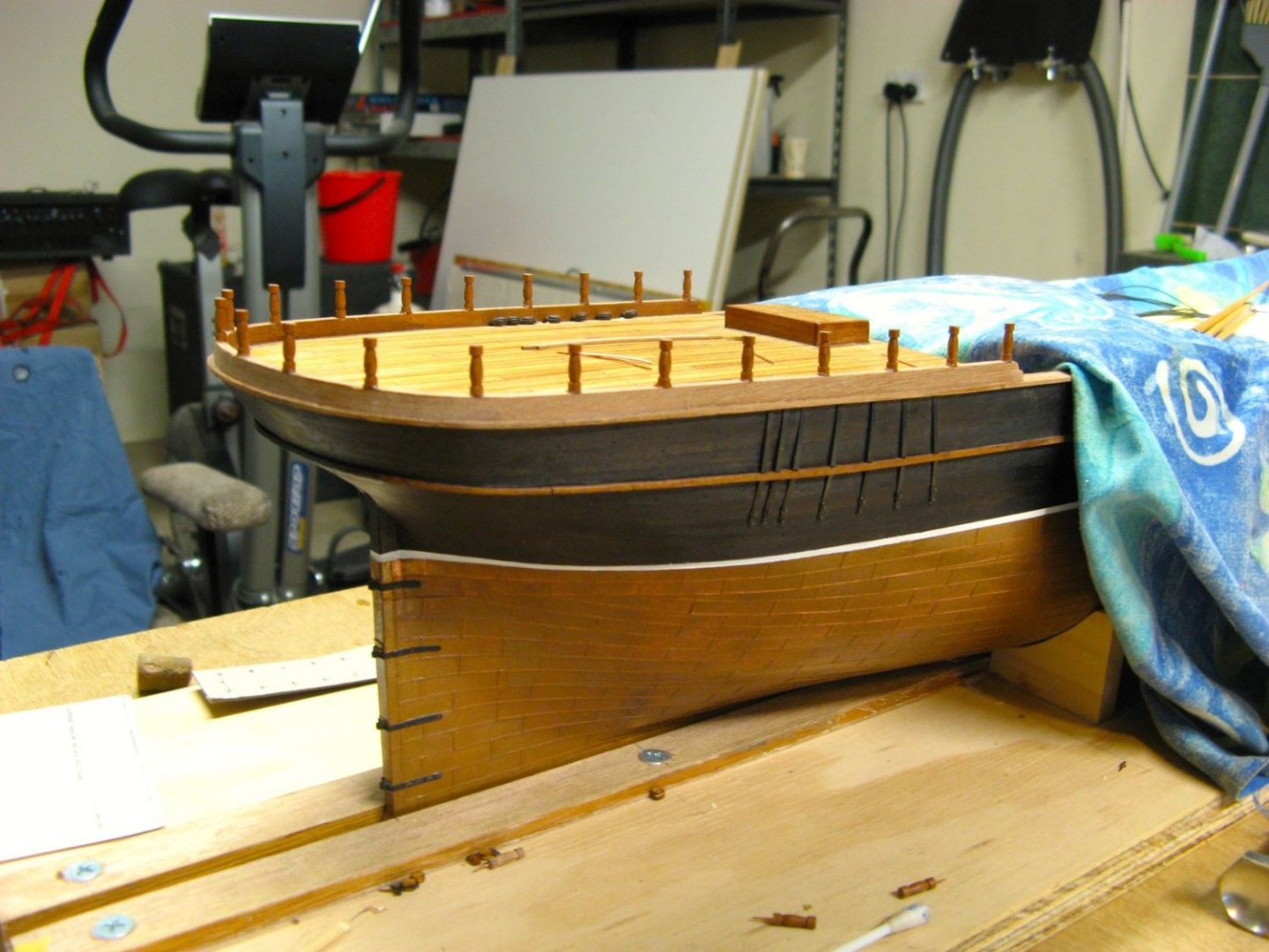
Top Rails: using the lower rail as a template was a failure. My construction skills are not sufficiently accurate. I ended up pinning thin card to the centre ballustre at the stern, and the port and starboard ones at the other end, then marked out the ballustre tops on the underside of the card and created the template from that. The template was copied onto transparency film and pinned onto the ballustres with some thin card under to provide support. Constructing the rail on top of the ballustres allowed me to "bake" the sweep of the sheer into the rail. The rail was made with from two parts laminated together, with the scarfed joints of the top piece, half way between the lower joints. The sections were weighted down whilst the glue dried. The top scarfs were dowelled through to the underside of the lower half. After the pva had set, the rail was dowelled with copper wire and epoxy into the ballustres. The ballustrade across the front of the poop deck was constructed in a similar fashion. I apologize for the lack of (detailed) pictures, the process completely consumed me for a couple of weeks. It's not perfect, but I'm content with the finished product. Grant..JPG.b44b2ce878ef060bdffa1b8b82cb30c8.JPG)
.JPG.de9bc98dd921862e39f4620e03a4cd32.JPG)
.JPG.f0a34fe317915945780c74930409d9f8.JPG)
.JPG.1abd4378792b94e561294734617a3605.JPG)
-
I have need of plans for the ship's boats for my Harriet McGregor build, circa 1860. Can anyone suggest where I may obtain these? Grant
.JPG.a0f19b26aea6bc5dc68ddd275210f480.JPG)
-
Harriet McGregor by Boccherini
Boccherini replied to Boccherini's topic in - Build logs for subjects built 1851 - 1900
Wefalk, thanks for the details, I'll keep them in mind when working small dia wire. The profile was used to form the balustres (thanks for the correct terminology). The under side of the profile is the cutting edge. The profile is sitting on top of a tool in the post, which gives it the correct height. Like you, I'm lazy, removing/replacing tool posts is a pain. Fortunately, the cross slide is large enough to accommodate this arrangement. Roger, thanks for your two bob's worth. I agree, the metal belaying pins are better. Grant. -
Harriet McGregor by Boccherini
Boccherini replied to Boccherini's topic in - Build logs for subjects built 1851 - 1900
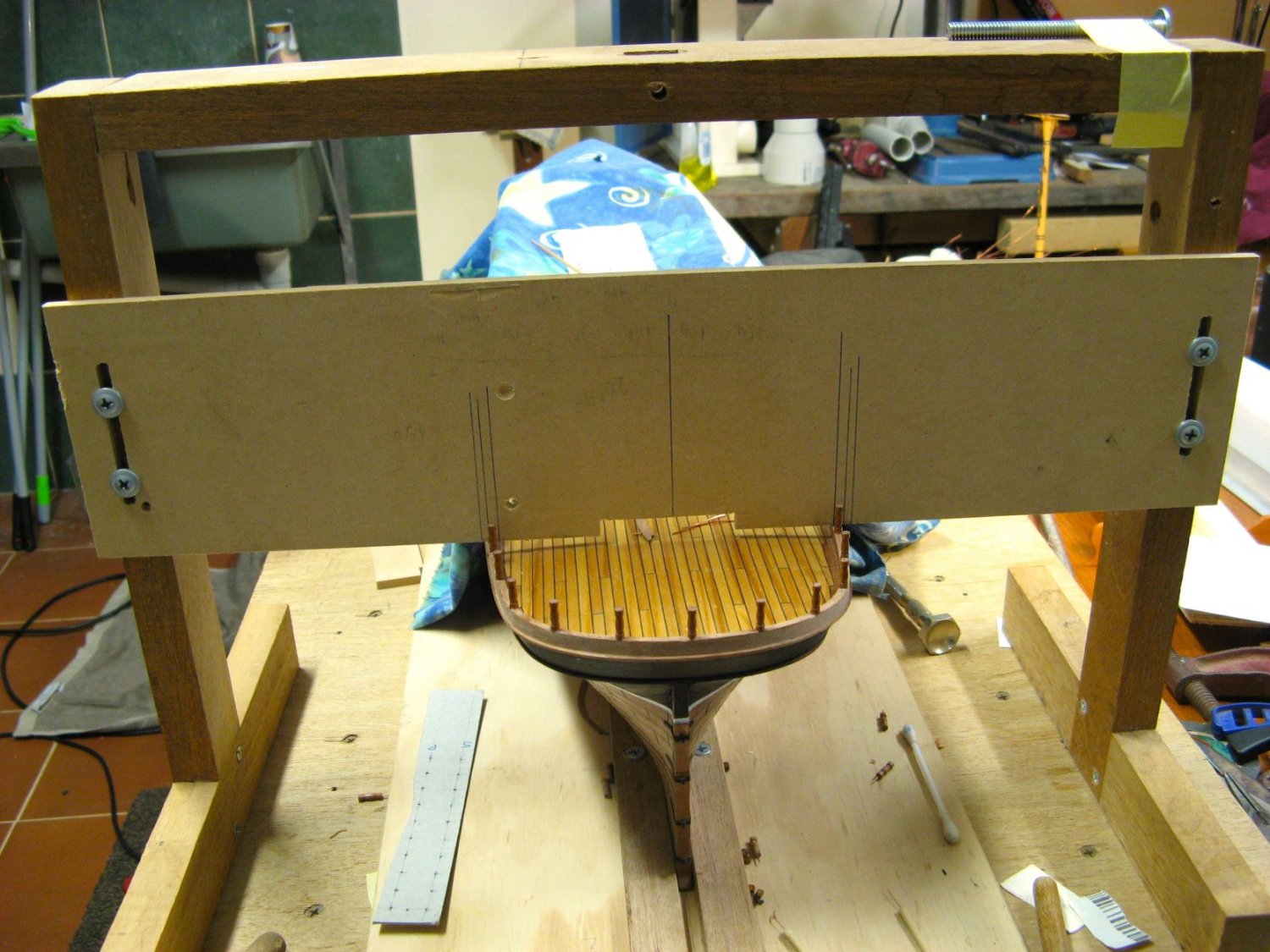
Wefalk, interesting idea, I'll look in to that. I tried using copper wire in the lathe, epic fail. Most bent under the pressure of the file. This is reasonably idiot proof. Heating something then hitting it doesn't leave much room for error. The only drawback is limited size options. Balustrades and rails After spending the time and effort in making the first profile, I re-discovered Rule #1 for profiles: it must be a "negative". I used part of an old hacksaw blade for the profile. The dowel in the collet is 4mm, turned down to 2.9mm prior to shaping. The first 10 or so self destructed before I got the hang of the process. All the pieces were cut off slightly longer than required, sealed with a coat of poly and drilled to take a 0.5mm copper wire pin. I made a cheap nasty jig to hold the pieces while squaring the ends and making the lengths identical. And another jig to give the balustrades the correct angle top and bottom. The copper wire was epoxied into the balustrades at this point. I really do like laser levels. The back board is perpendicular to the keel, the vertical lines helped to set vertical in the other plane. It's not 100% with my eyesight, but acceptable. The hand drilled holes in the lower rail were slightly larger than the wire to give a bit of wobble room, aided by the flexible copper wire, everything worked out ok. They could only be done in pairs, I had to wait for the epoxy to set before moving on. Slow process. Quite pleased with the end result. Grant..JPG.89cfeb5d78b85edc97160d820c14d2d3.JPG)
.JPG.95705e40424f58e3d81842077f1fa6b1.JPG)
.JPG.749d55b1ebdda8faea4c0a0bf26e3e4f.JPG)
.JPG.f1d5aafed0c48990f62641ac3167059b.JPG)
.JPG.9c1f61b90dd151790b6eec586a03d036.JPG)
.JPG.354bdbc333bba79a5ad62831dc07919b.JPG)
.JPG.a8d8d335b2fb77b44b5ef373c64bcd8f.JPG)
-
Harriet McGregor by Boccherini
Boccherini replied to Boccherini's topic in - Build logs for subjects built 1851 - 1900
Installing the deadeyes/chainplates for the mizzen mast had been holding up progress for some time. The only option was to cut slots and hope the damage could be hidden. I was not happy with the first batch of chainplate cleats, the new ones are significantly better. Domed fixings for the chainplates/cleats proved easier than expected. 1mm copper tube with an internal diameter of 0.5mm brazed onto 0.5mm wire, trim/file down to 0.5mm thickness. The dome was created using a small nail punch with the fixing held in a steel plate. It all worked out better than expected.😁 Grant..JPG.4140facfd058a5345745b4423ca818a3.JPG)
.JPG.c54f70f93f06abc3b89e30aafe5e5893.JPG)
.JPG.30832107417504b46d5dcb5bac3e4df5.JPG)
.JPG.906f045d95428abef704f5d8bad3f8bb.JPG)
.JPG.5e4797226f33581cefecc71f5a83d62b.JPG)
.JPG.9bf04d8aaa1149065b2b117242692bcf.JPG)
.JPG.9fd8f21b020681ae44af3b86114432bc.JPG)
-
Harriet McGregor by Boccherini
Boccherini replied to Boccherini's topic in - Build logs for subjects built 1851 - 1900
I've had a productive 7-8 months, enjoying being retired. I'm currently out of the workshop for a couple of weeks, recovering from a hip replacement, I'll use the time bring the log up to date. Apologies for the dodgy photography. Deadeyes, strops and chainplates. All the pieces were made at various times over the last year or more. I needed a jig to hold the assembled pieces while securing them. The pins were cut off 0.5mm past the strop, then centre punched to spread out the end, then domed by using a small diameter nail punch. The finished assemblies after touching up the blacking. It is hard to pick up the "cheat" used to fix them together. The strops are loose enough to allow the deadeyes to rotate as needed. Grant..JPG.2582c819dca8403cc03cda7b503491b8.JPG)
.JPG.ef077579ef5755485a05f2020e9e112d.JPG)
.JPG.50a771718211ccdbda316a07852bd516.JPG)
.JPG.f67905bab53107059652272deae6a4dd.JPG)
.JPG.b436e3b39f1c7753886970f4c3c77307.JPG)
-
Bob, thanks for the detailed explanation.
-
Thanks for the information.
-
Were the roofs (rooves?), on the deckhouses (in the 1850-1860's), caulked like the decks for waterproofing? Would whatever the technique used be visible? Thanks, Grant.
-
Thanks John. I'm happy with the finished product..
-
This is my solution to the baluster installation.

-
Thanks for the suggestion John.
-
I'm currently working on the balustrade/rail around the poop deck on an early 1860's barque. It appears to be a awkward job getting 21 balusters correctly aligned, then sitting the rail on top. Is there a "correct/accepted" way to go about this? Or is it a case of "whatever works for you"? Regards, Grant.
-
tweezer reccomendation
Boccherini replied to Boccherini's topic in Modeling tools and Workshop Equipment
Gentlemen, thanks for the help/recommendations. I had a look at the Dumont offerings Wefalk, impressive tools. Unfortunately, I seem to have reached an age where things are inadvertently dropped onto the floor. I'm sure the tweezers won't disappear for ever like the small items regularly do, but the financial pain will be significant. Mark, steel cap boots in the workshop? Regards, Grant. -
I'm looking to purchase some straight and bent tweezers for rigging work. I would appreciate some recommendations for reasonable quality items, where the ends/tips properly align when squeezed together. Thanks, Grant.
-
Phil, thanks for taking the time with that very detailed reply. Regards, Grant.
-
Phil, thanks for the input. 1860, timber mast, fixed gaff. Plans (they MAY be a bit vague), don't show a jack stay . My issue is how to attach the blocks to the mast. Regards, Grant.
-
I have 3 pairs of spanker brail blocks to fit to the mizzen mast. I can't find any reference on how they are set up in Underhill's book. I am assuming they are supported with thumb cleats on either side of the mast. Are the "pairs" of blocks rigged on the same loop around the mast, or are they rigged separately? Any pictures would be appreciated. Thanks, Grant.
-
Gentlemen, thank you kindly for sharing your techniques. Much appreciated. Grant.