Boccherini
-
Posts
380 -
Joined
-
Last visited
Content Type
Profiles
Forums
Gallery
Events
Everything posted by Boccherini
-
Harriet McGregor by Boccherini
Boccherini replied to Boccherini's topic in - Build logs for subjects built 1851 - 1900
John, that took a while to figure out, some weeks (months?) my brain is not quite what it used to be. At least I eventually arrive at the right place. Thanks Steven. Grant. -
Harriet McGregor by Boccherini
Boccherini replied to Boccherini's topic in - Build logs for subjects built 1851 - 1900
Not sure what to call this structure. It took three attempts to obtain a satisfactory result, partly as a result of not understanding what the plan actually represented. Got there in the end. The "roof" has since been painted white. I lightly glued two pieces of wood together (at the ends and in the middle of the cut outs), set that up on the mill, cut the slots for the "bars" top and bottom, then cut out the openings. The rest was just gluing the bits together similar to the wheelhouse. The "glass" is cut from transparent photocopier film rubbed with 400 wet/dry to give a frosted (salt crusted) appearance. Grant..JPG.d80f9e688670bef29ce9b3cbe4b2a9af.JPG)
.JPG.e4dfad6bbbc0f5f0ecc88c9c73c4897a.JPG)
.JPG.212311d25f6a2786590622e15010207a.JPG)
.JPG.4302171c4673592582f6e2ff9cbdada3.JPG)
.JPG.d711e977f6911e1f80d1ed8cae897c84.JPG)
-
Henry & John, thanks for your contributions. Time to decide how to tackle this & do it. Thanks again, Grant.
-
Thanks Henry. Great painting. Mr. Green had an eye for detail. John, thanks for that, I can't enlarge it much. It starts to pixelate (right word?). I can't imagine the spreader being a single piece of metal poking out from the collar, probably wouldn't be strong enough. A "T" section spreader? Any thoughts? Regards, Grant.
-
John, I've had a closer, magnified look at the picture, I suspect you're right about the 1 spreader/crosstree. Late middle age eyesight often sees what it wants to see. Would the spreader would be fore or aft of the mast? Rectifying the error should be fun. Thanks again for your help. Allan, no worries. I'll get to your recommendations over the weekend. Regards, Grant.
-
John, thanks for the photo. it shows some differences from Underhill's drawings. Different point of time in the her life? I have squinted very hard at the far side of the mizzen top / top mast. There seems to be a pair of shrouds with ratlines, not 100% sure though. Regards, Grant.
-
Chris, thanks for the intervention. Allan, 1860, Harriet McGregor. Boccherini, an underappreciated composer. His guitar quintets grabbed my attention, particularly this: https://www.youtube.com/watch?v=IgEaS_d6qUE . I'll have a listen to the "Celebrated Minuet in cello concerto No. 9" Amateur, that picture has a very similar mizzen set up as my plan (which shows no clear detail of the top). I now know that my top, taken from "Masting & Rigging", may not be correct for the ship. Henry, I forgot I had this picture from the Hobart Maritime Museum (?), which seems (possibly), to show a pair of crosstrees/spreaders with shrouds terminating half way up the mast and futtock shrouds connecting onto the main shrouds part way down. Is this the painting you are referring to: Rob, Thanks for your input. My rigging plan also shows no spanker boom guys, yet "Masting and Rigging" includes them in the description of rigging for spanker booms. The book also describes the boom sheets as having 2 blocks, my plan shows only one. Harriet McGregor was a small ship, 330 tons for memory, would this explain the rigging oddities? Regards, Grant.
.JPG.df3999d2a208bb93586013dc529780c5.JPG)
-
Whilst playing around with a shroud pair to see how it looked/worked out, I noticed a several problems with the mizzen top. The main issue: how will someone get onto the top from underneath? There are no futtock shrouds, because the top mast has no shrouds according to the rigging drawing. Do I remove the planking and leave the crosstrees? Or cut an access hole through the planking? Or something else? There is no detail for this in the plans. I haven't been able to find a reference in Underhill's "Masting & Rigging. Doesn't mean it isn't there, I may have missed it. Suggestions are most welcome. Regards, Grant.
.JPG.d77003d97c7c641d223eeff6f76942b0.JPG)
-
Harriet McGregor by Boccherini
Boccherini replied to Boccherini's topic in - Build logs for subjects built 1851 - 1900
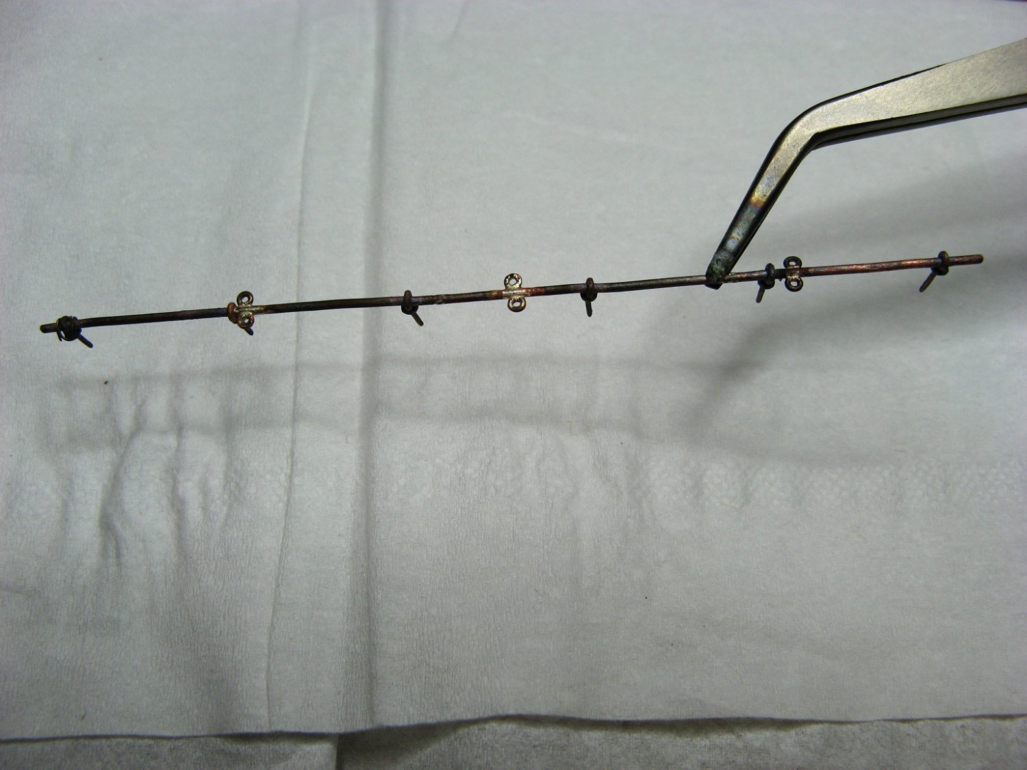
The last 3 months have been quite productive. I've been focused on doing stuff, consequently there are "pictorial" gaps in the process. Mizzen Jackstay: made with 0.5mm wire for the eyes and 0.8mm for the stay This next step was a tad frustrating. No matter how carefully the eyes were positioned, they ended up slightly out of alignment. I'm assuming it is due to expansion of the copper wire when heated. Perhaps I should've brazed the eyes in pairs instead of one at a time. Fortunately, slight variations in the length of the shackles were used to even things up a little. Grant..JPG.95a001100831a86cd93dba97d55bfb4d.JPG)
.JPG.b8290e35d978df099b228b1b1647ca61.JPG)
.JPG.5ea8f330f1ec9a1a62330270e7cb96ef.JPG)

.JPG.2072f3c549920bd73f5d434f3f661934.JPG)
-
You continue at a furious pace. I spend ages staring and wondering what to do next, then spot something that should have been done several months ago. Are the stays supposed to just touch the spreaders? Or do the spreaders actually spread the stays a little? I've "stared and wondered" how to get the spreaders just right without actually installing the stays then adjusting the spreaders to fit. Regards, Grant.
-
Just finished catching up Vlad. Nice work. In particular: the two deck fixings for the double fore stays. Regards, Grant.
-
Thanks Wefalk.
-
Alan & Gregory, it's my current model, Harriet McGregor (1860), 330 ton 3 masted barque. Chris, thanks for the link. Attractive, well thought out product. I'm a bit of a masochist, so will continue with the home made approach. Personally, there is greater satisfaction in doing things this way. Regards, Grant.
-
I'm fiddling around with metal strops and eyes on blocks......it's very fiddly (and time consuming, also frustrating etc). I've noticed pictures and drawings of wooden blocks with eyes that appeared to be bolted through the block. For example: https://c8.alamy.com/comp/DK91FK/wooden-blocks-on-an-old-sail-boat-DK91FK.jpg Were these bolted right through the block top to bottom, or some other method? Any idea of the period when they were introduced? Were they used throughout the rigging? Or only in certain areas? Or on smaller sizes of blocks? Thanks for any assistance. Regards, Grant.
-
Glen, interesting project. I'm enjoying watching it develop, your good humor is a bonus. Regards, Grant.
- 134 replies
-
- 5
-

-
- Captain Kidd
- bottle
- (and 3 more)
-
Cutty Sark Photos - Free!
Boccherini replied to Kevin-the-lubber's topic in Masting, rigging and sails
Kevin, thanks for making this available. I've just downloaded the zipped file, won't be able to check it until later. If there are any issues, I'll let you know. Regards, Grant. -
Vladimir, just finished scanning through the last few pages of your log, I'm enjoying your small scale metal work. The dolphin striker is quite impressive. Regards, Grant.
-
Thanks Ben. Grant.
-
Allen, looks like an interesting project. You're off to a good start. I've had similar issues with picture orientation. I stopped using my phone's camera and the problem disappeared. The ancient 8 mega pixel Cannon I use also has the advantage of a macro function. Regards, Grant.
-
Lofting article
Boccherini replied to a topic in Building, Framing, Planking and plating a ships hull and deck
Guy, Roger's comment above covers it well. You could try and obtain a copy of Underhill's "Plank On Frame Vol 1". He runs through the whole process in an easily understandable and encouraging fashion. That book was my bible whilst lofting the frames for my "Harriet McGregor". It has been a constant source of inspiration/construction techniques since. I borrowed (budgetary constraints) a drawing desk similar to the one you have; a couple of set squares, a set of French Curves, a 600mm flexible curve, a bunch of pencils and good quality erasers completed the kit. It worked out well. My drafting background: 5 years at high school 45 years ago. Take your time and keep the pencils sharp. You'll be fine. Regards, Grant. -
Interesting video. Grant.
-
Harriet McGregor by Boccherini
Boccherini replied to Boccherini's topic in - Build logs for subjects built 1851 - 1900
Thanks Wefalk. -
Harriet McGregor by Boccherini
Boccherini replied to Boccherini's topic in - Build logs for subjects built 1851 - 1900
Wefalk, it appears to be mostly motor noise. Wheelhouse: The "carcass" is constructed from 3mm ply with whatever was lying around to cover the top. A pear veneer was glued on with pva. Normally, I would've used contact cement, but a brief internet search brought about a change of glue. This appears to be a better method. It requires pva to be placed on the surface to be veneered only and quick, moderate clamping before the veneer starts curling. The reason for using milled slots for the corners and sides: guaranteed vertical timbers. I've found gluing thin strips difficult to correctly locate and the strips are prone to "random movement" while placing weights on top. The rest is just sticking bits of wood on until it's completed. I may sand the roof and paint it to mimic actual practice......or not. That is about where I'm currently at. Grant..JPG.e36c5778e3bf4c88cadc00d1cfe01090.JPG)
.JPG.c6492f60e99069b800dc281c52da68c8.JPG)
.JPG.a454393a53852d2039182691c56de1e9.JPG)
.JPG.f5a367ebbbc8da39657f07e54f583cce.JPG)
-
Harriet McGregor by Boccherini
Boccherini replied to Boccherini's topic in - Build logs for subjects built 1851 - 1900
Thanks Wefalk. Your suggestion is noted. I think it may not have been practical in this instance, the outside diameter of the wheel is a smidge over 19mm. Thanks Vladimir. Tony, they are a useful addition to the workshop. I've certainly had no regrets purchasing the Proxxon, it has done all that I've required of it. The only downside so far........it's quite noisy. Grant. -
Harriet McGregor by Boccherini
Boccherini replied to Boccherini's topic in - Build logs for subjects built 1851 - 1900
Wheel: Thanks to Ed Tosti and his most excellent tutorial. I had to make a rod to work from, the MF70 only has a 3 jaw dividing head. The first attempt was a disaster, due to forgetting the grain direction is quite important. I changed tack, and glued 2 thin, square pieces with the grain at 90 degrees, then glued that piece to the end of the rod. Amazingly, it didn't drop off until after the wheel had been separated. The square addition was rounded, then the wheel parts cut out and drilled. The easiest way to make the spokes was with a drawplate, glued in, and the wheel cut off. The first and second attempts side by side. Grant..JPG.13eb1a556e9d75562af052c3a6076519.JPG)
.JPG.1f013192de313adb43f60b083b5324c2.JPG)
.JPG.400869b9773327ff62b6034fcce42d5e.JPG)
.JPG.630dfcaeda4b915851e0036c2aa45025.JPG)
.JPG.33688cac9d1f03037dc579772aa51fbf.JPG)
.JPG.e2a4b1428786a93cd81c690ed821cbaf.JPG)