Boccherini
-
Posts
380 -
Joined
-
Last visited
Content Type
Profiles
Forums
Gallery
Events
Everything posted by Boccherini
-
 Mir0n, that is a lovely piece of workmanship. Regards, Grant
 -
Raymond, that is a fine looking cross section, the extras have made it an interesting model. Congratulations on a job well done, something to be proud of. Regards, Grant.
-
Harriet McGregor by Boccherini
Boccherini replied to Boccherini's topic in - Build logs for subjects built 1851 - 1900
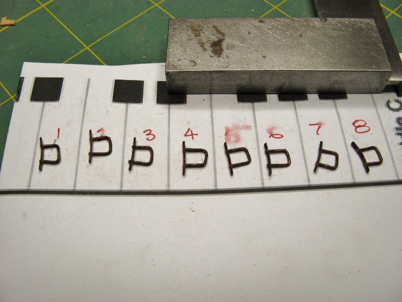
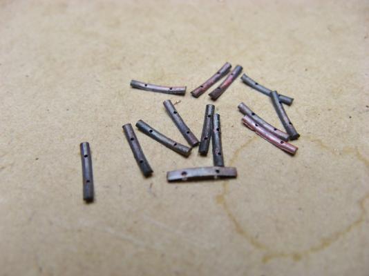
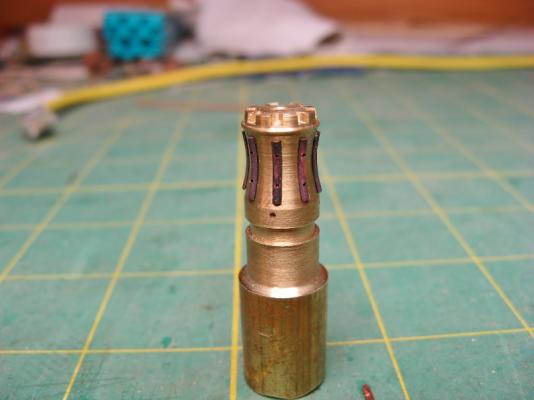
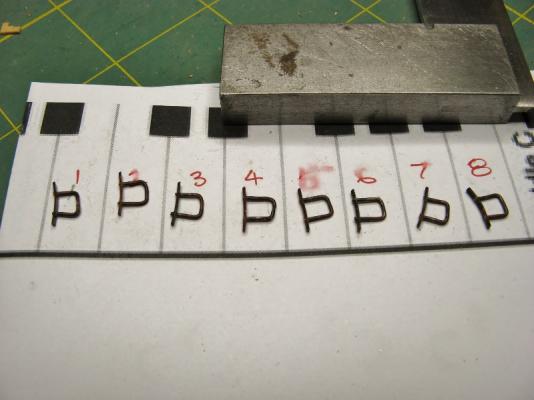
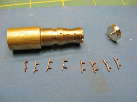
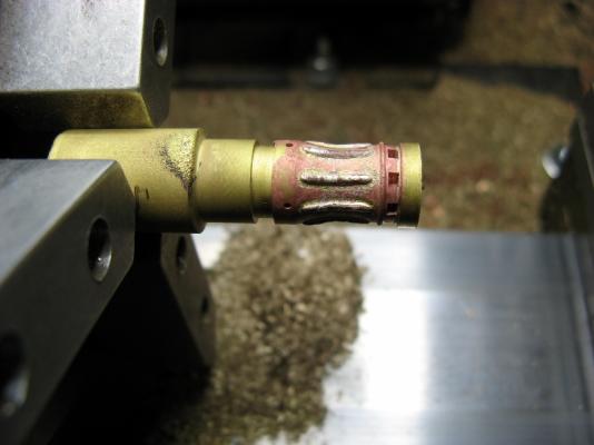
Thanks David and John. Capstan V2.0 was worth the extra work, it's much better looking than the original. The whelps were made from some 1mm wire filed down to half its thickness, cut to length and drilled to take locating pins. Contact cement was used to hold the whelps to the capstan whilst drilling. The loop of wire used to make the pins made it easier to solder and gave me something to grip while finishing the shape of the whelps. I ended up having to use a full size oxy/acetylene torch to heat it up (my little butane torch was way "under powered"), I think it was slightly overcooked as the solder left some rough patches around the whelps. They have been mostly scraped/rubbed out, but are still slightly visible. Grant.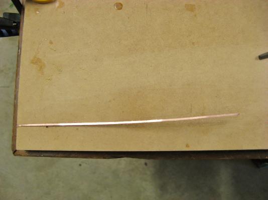

-
Harriet McGregor by Boccherini
Boccherini replied to Boccherini's topic in - Build logs for subjects built 1851 - 1900
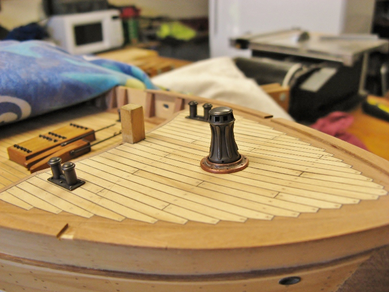
rpeteru, Tom & Michael, thanks for your taking the time to leave a comment. Michael, the idea of the locating pins is something I picked up from reading Underhill's books. I envy your machining skills to do that out of a solid metal piece, my abilities in that area are not up to that kind of work as yet. I decided to experiment on this capstan with soldering the whelps on, being only 1mm x 0.5mm, I had some concerns of them melting before the solder ran. Everything worked out nearly perfectly first time. Nice to know this happens occasionally. First picture after "pickling", then after blackening.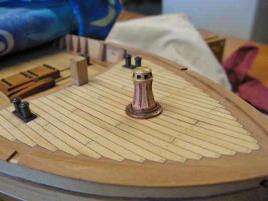

-
Harriet McGregor by Boccherini
Boccherini replied to Boccherini's topic in - Build logs for subjects built 1851 - 1900
Thanks for all your encouraging comments. John, the scale height including the base equals 1.2m (4') actual height. I have started v2.0, which is equivalent to 1.1m (3'8") and has a different shape, more in keeping with the picture you posted several weeks ago in another thread. Bob, I have no idea, my plans are vague/contradictory. It's down to "does it look right?" Grant. -
Danny, nice workmanship on a fiddly item. Regards, Grant.
-
Batavia by *Hans* - FINISHED
Boccherini replied to *Hans*'s topic in - Build logs for subjects built 1501 - 1750
Hans, just had a quick browse through your log. Very nice work. Congratulations. Regards, Grant. -
Harriet McGregor by Boccherini
Boccherini replied to Boccherini's topic in - Build logs for subjects built 1851 - 1900
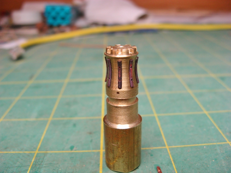
John, Bob, Mark & Pete, thank you for the kind words. First attempt on the body of the capstan. I'm not sure the proportions are quite right, back to the drawing board. Grant.
-
Looks sweet John. Regards, Grant.
-
Harriet McGregor by Boccherini
Boccherini replied to Boccherini's topic in - Build logs for subjects built 1851 - 1900
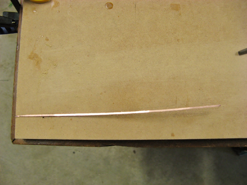
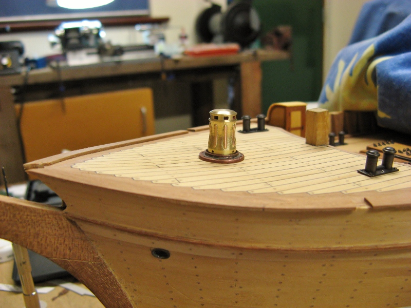
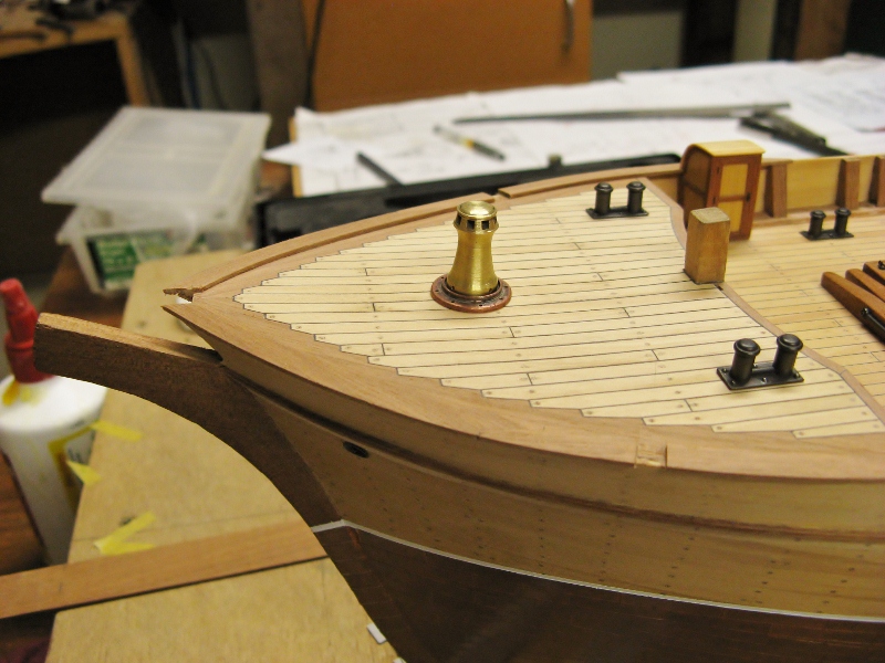
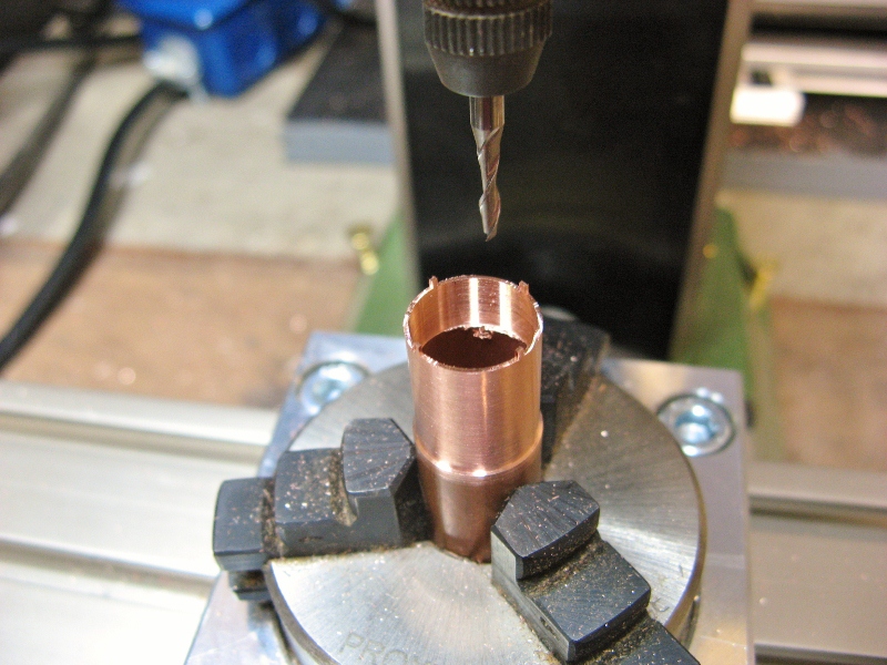
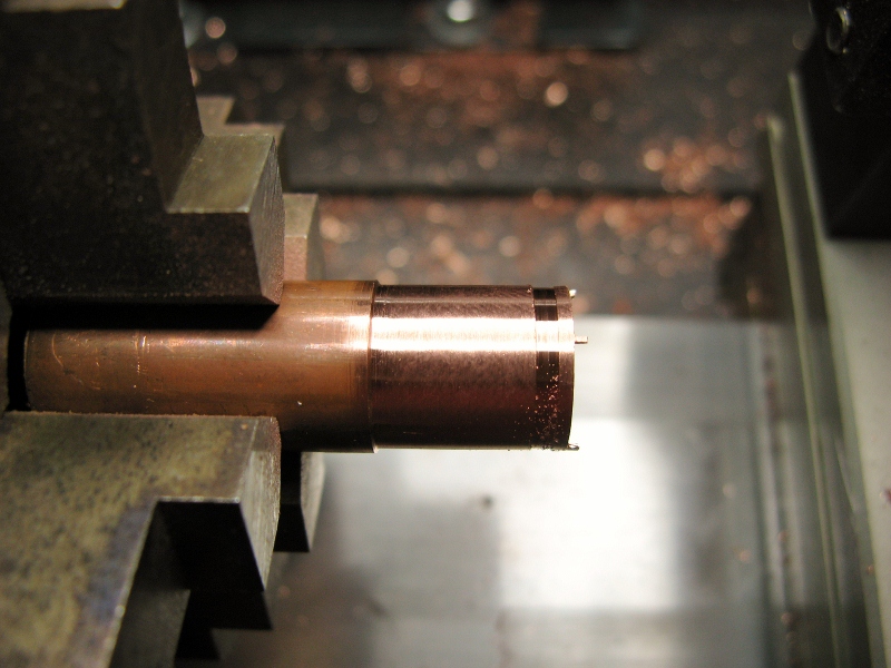
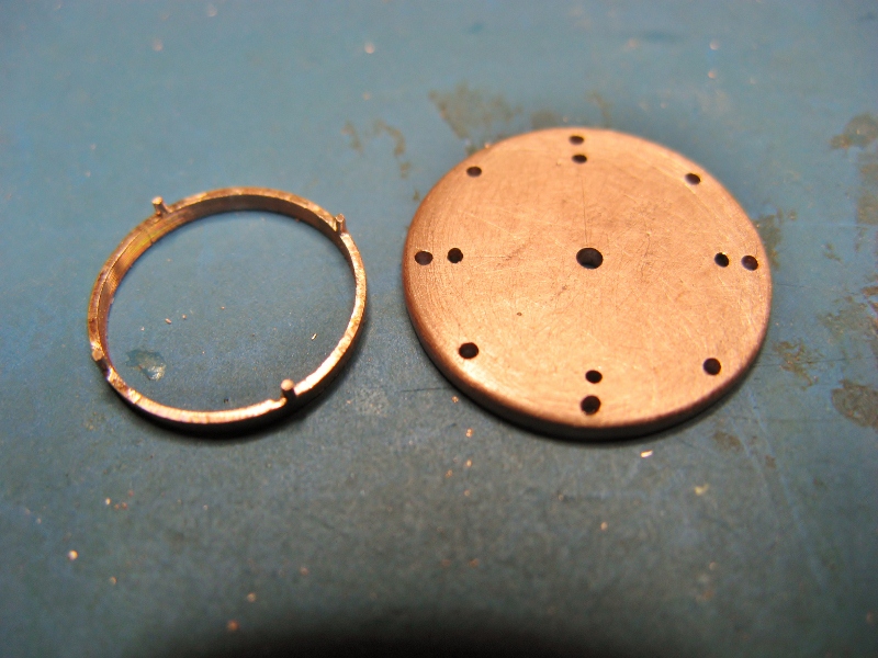
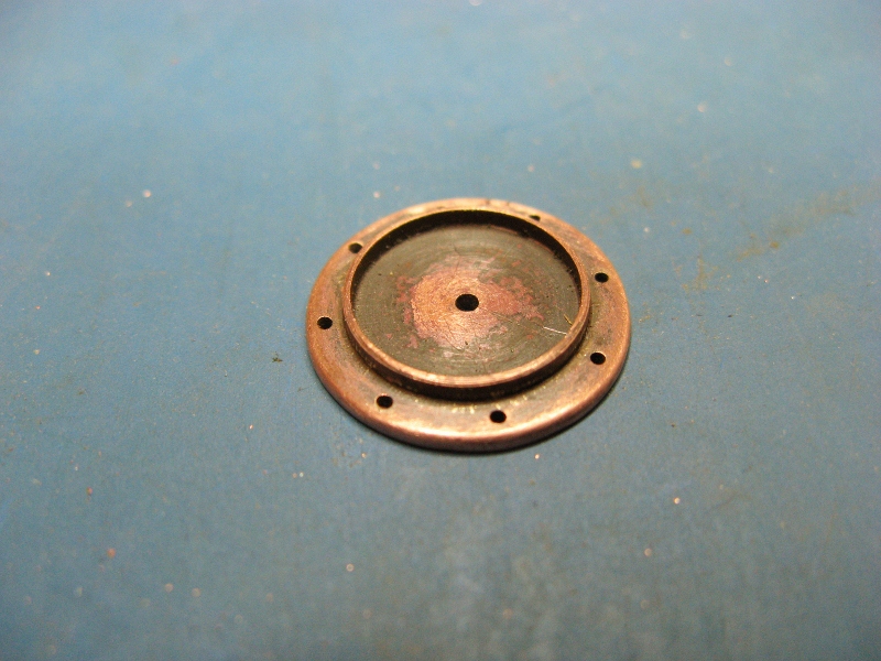
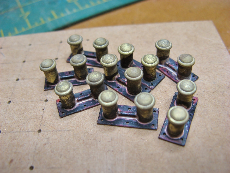
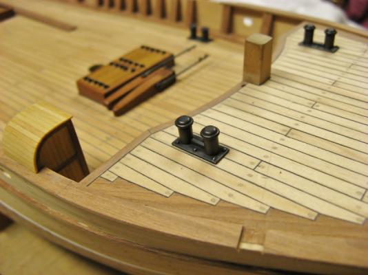
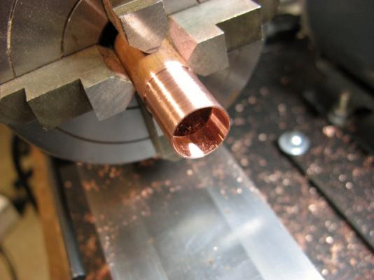
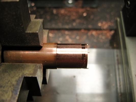
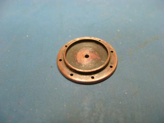
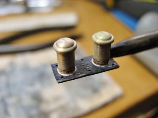
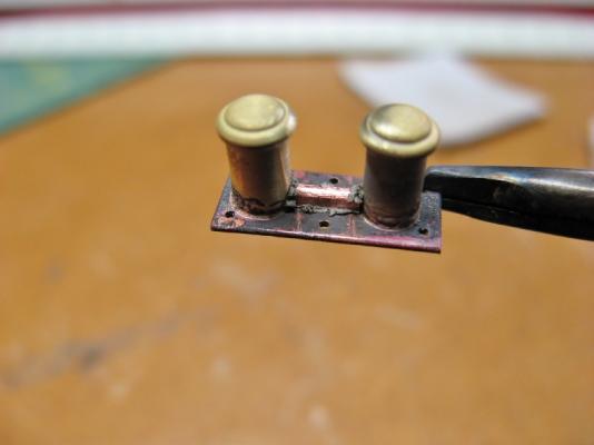
E&T, thanks for the comment. I decided to solder the "bolts" to the bollard base plates, this process taught me something new about solder paste. When doing multiple joints on one piece, you need to heat the whole piece and do them simultaneously, or only put paste on the parts you are heating. I made the mistake of putting paste on all the bolt heads, then trying to do one end and then the other.....disaster. By the time I started heating the other end, the solder paste had dried out and would not make the joint. Had to pull the bolts out, clean off the crud and re-do them several times before realizing the cause and solution. This process messed the whole bollard assemblies up a little, they don't look as good as they might've. Probably would've been better to just push the bolts in after epoxying the bollards to the deck. Frustrating but instructive time. After pickling and then scrubbing in acetone: In place after chemical blacking. Next project is the capstan base plate. The copper ring is from a piece of 1/2'' copper pipe. The inside was turned to the correct diameter with a boring bar, then the outside turned down to the correct thickness. Lugs were milled into the bottom of the ring, then the ring was half cut from the pipe at the correct height, the final separating cut had to be done with a jewellers saw. It proved impossible to separate the ring from the pipe with the lathe cut off tool, it collapsed due to the lack of thickness. This piece took 3 attempts to get it right, more instructive frustration. The base plate is 16mm (0.64") diameter. The pieces were then soldered together. Another lesson re learned (I am still a novice lathe/mill user), if you are removing and replacing a work piece in the lathe chuck, always make sure it goes back in the same place in the chuck. I now have a mark on one of the chuck jaws (to differentiate it from the others), I file a small mark in the work piece where it meets the end of this jaw.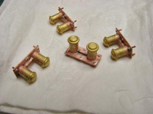


-
Gentlemen, I am grateful for the all pictures, very helpful. Thank you. John, the beard makes the picture. Give him a big hat and guitar......ZZ Top. Regards, Grant.
-
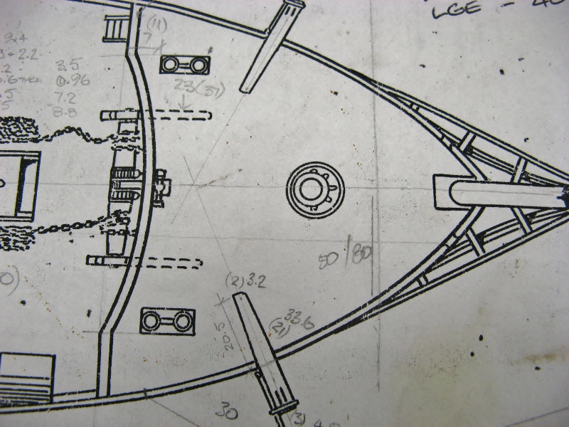
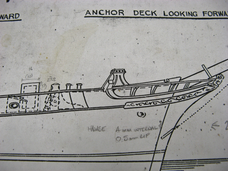
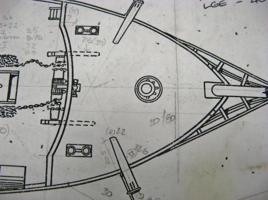
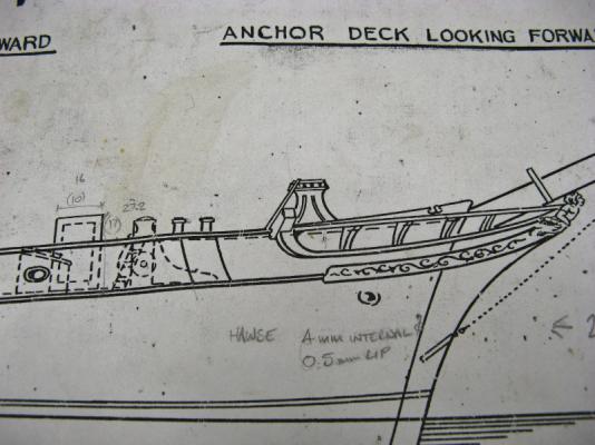
Does anyone have pictures / drawings of anchor deck capstans for merchant ships from around 1860? The plans are lacking in any real detail. This is what I have to work with at present: Thanks, Grant.
-
Harriet McGregor by Boccherini
Boccherini replied to Boccherini's topic in - Build logs for subjects built 1851 - 1900
John & David....... thanks. David, thanks for the reminder about different metals, I forgot to mention the difference in melt temperatures between brass & copper, now corrected. Regards, Grant. -
Harriet McGregor by Boccherini
Boccherini replied to Boccherini's topic in - Build logs for subjects built 1851 - 1900
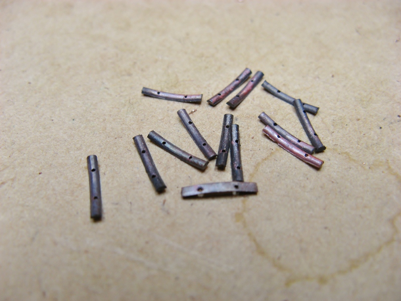
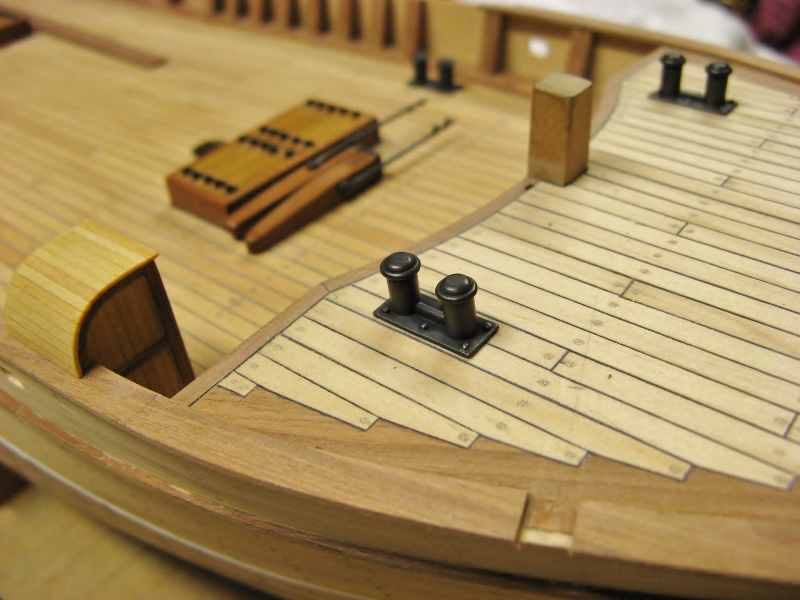
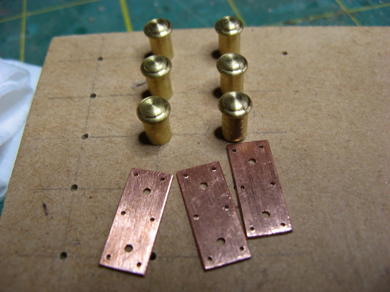
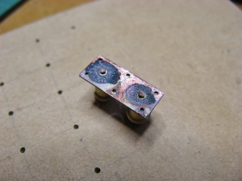
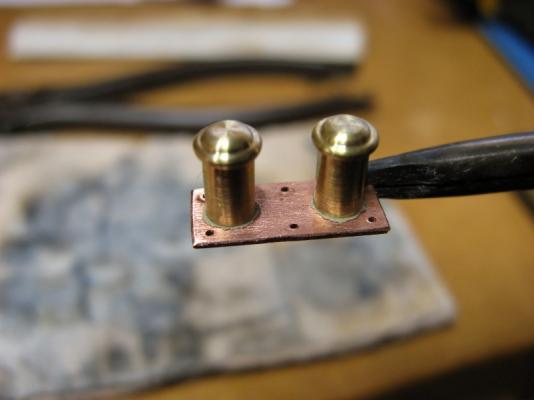
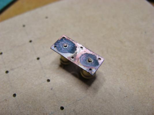
Bollards. Some of the details/proportions for these are approximate/educated guesswork. The base plates are 14mm x 6mm x 0.6mm (approx 1/2'' x 1/4" x 0.024"); the bitts, 7mm x 3.5mm dia.. I have included a brief description of the process, this may be useful to those considering trying their hand at soldering. I found the best results for soldering were obtained by putting some solder paste on the base of the bitts and pushing them down onto the base. The excess squeezed out around the bottom helped to form a fillet when the joint was completed. Same technique was used for the bar between the bitts, with the addition of some paste placed on at the ends. If the assembly has been heated correctly, solder should flow out around the pins on the underside of the base (pic 5). The assembly needs to be heated with care due to the difference in the mass of the parts, too much heat on the copper could cause it to sag or melt before the brass parts are hot enough for the solder to run. Another complicating factor in heating is the difference in melt temperatures, brass is lower than copper. Grant.

-
Harriet McGregor by Boccherini
Boccherini replied to Boccherini's topic in - Build logs for subjects built 1851 - 1900
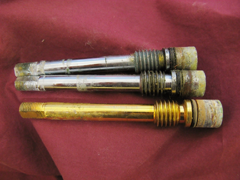
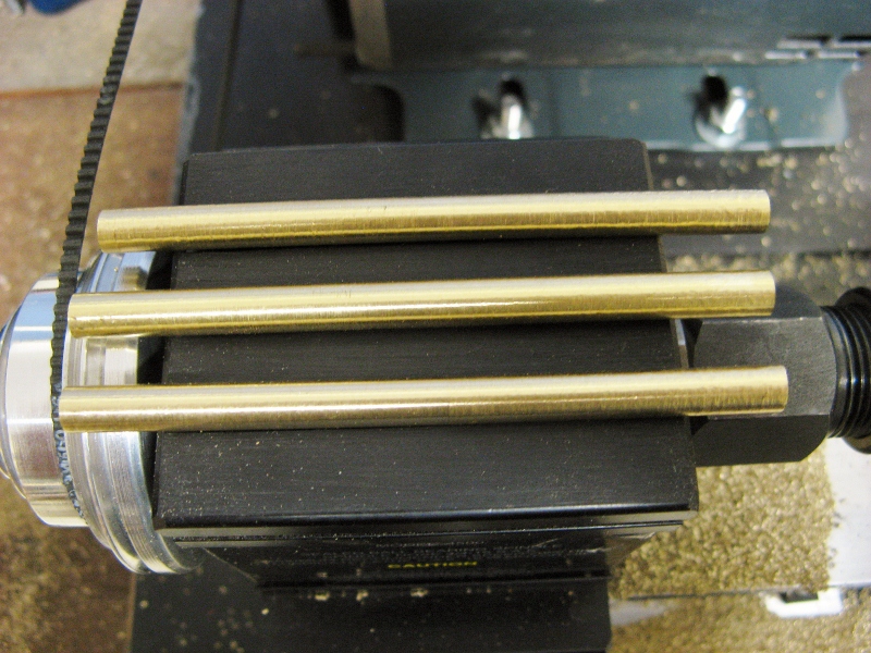
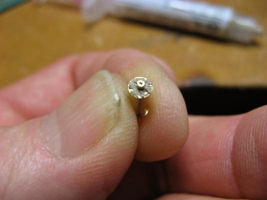
Thanks for the comments gents. John, David, I appreciate the reminder of the snagging potential. I was looking around for some brass rod to start making the double bollard sets, and found an almost endless supply of brass rod right under my nose.......spindles from tap top assemblies. I have a scrap bin from work loaded with these. They have a diameter of approximately 10mm (3/8"). Depending on the required diameter, they can produce up to 90mm (3.5") of usable brass. These have been rough turned down to 6mm prior to final shaping. Grant.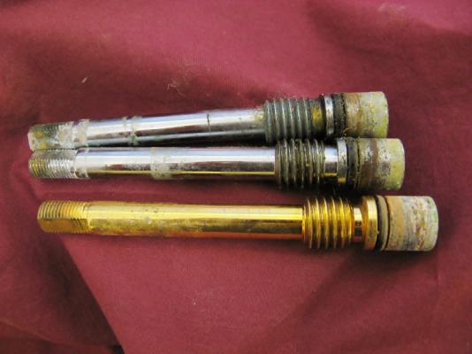

-
Harriet McGregor by Boccherini
Boccherini replied to Boccherini's topic in - Build logs for subjects built 1851 - 1900
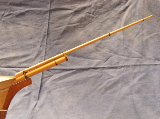
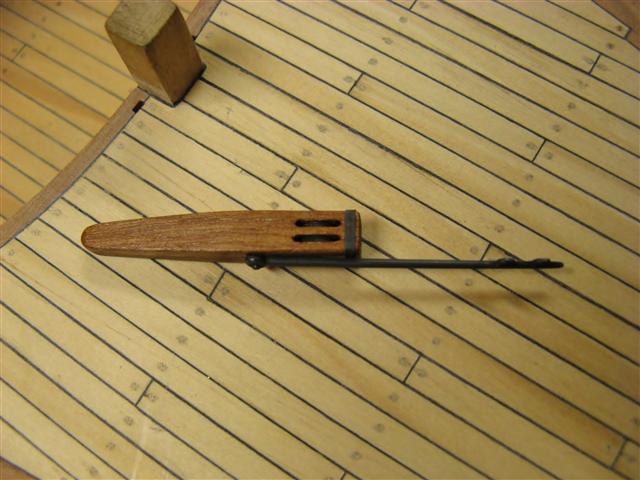
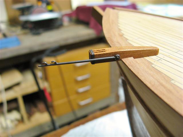
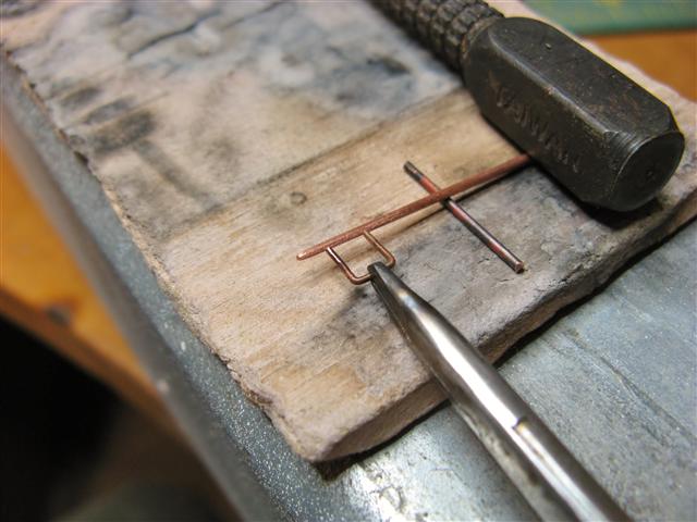
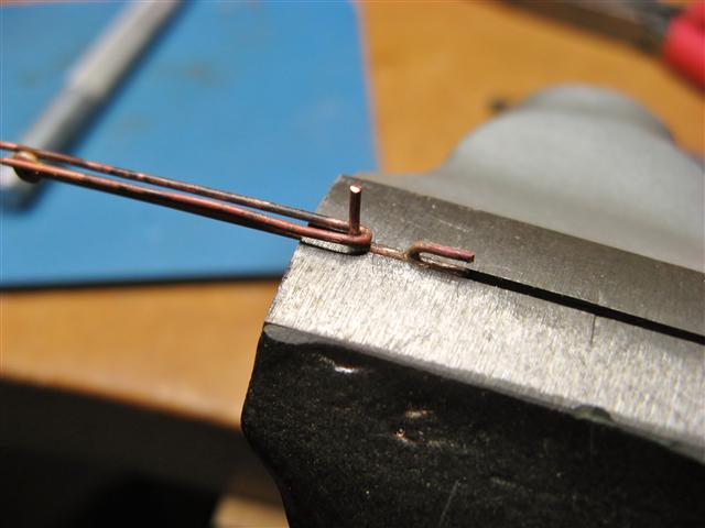
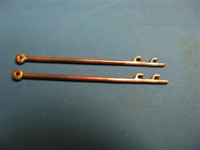
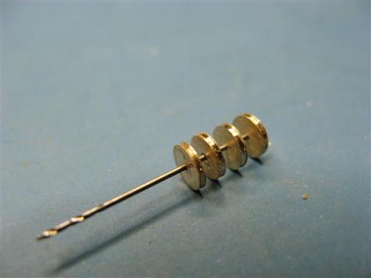
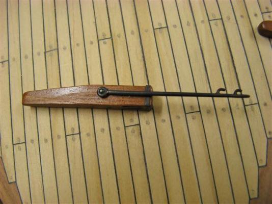
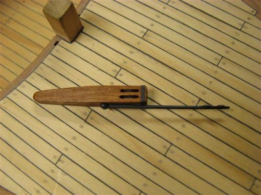
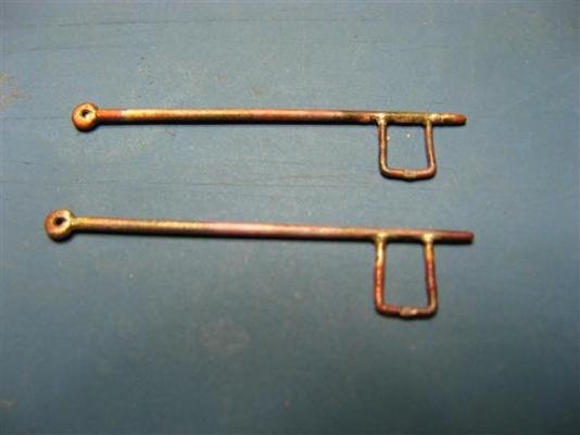
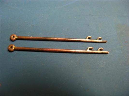
Whisker booms continued. I soldered a couple of pins to the whisker booms to fix them firmly to the catheads. Cathead sheaves are 4mm dia x 0.7mm thick, they are on a 0.5mm drill bit. All the parts were chemically blackened. The construction method is a variant of that shown by Harold Underhill in his Plank On Frame book. Grant.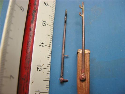

-
Harriet McGregor by Boccherini
Boccherini replied to Boccherini's topic in - Build logs for subjects built 1851 - 1900
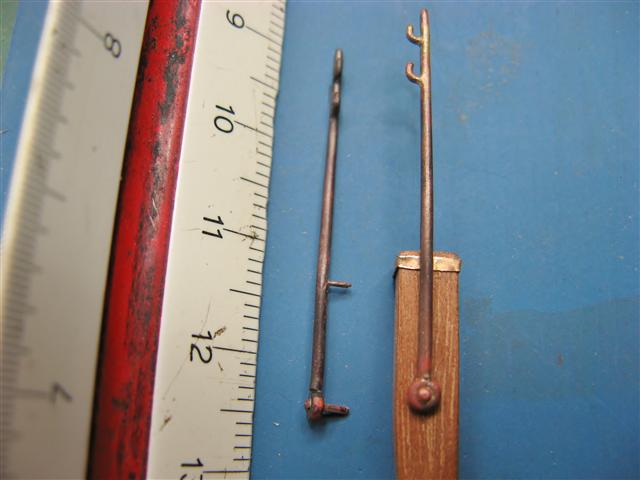
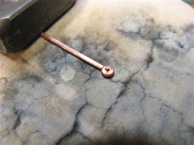
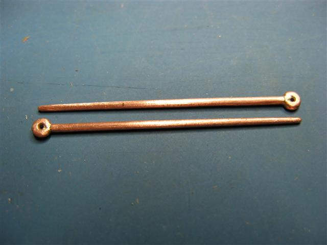
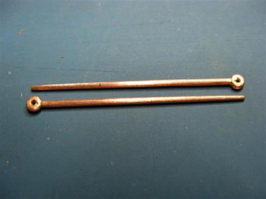
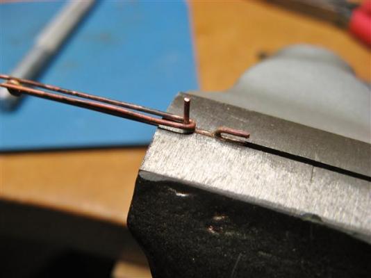
Slow progress has been made with the catheads, but they are now essentially complete. The whisker booms are made from 1mm dia copper wire, tapered slightly to improve the look. I filed a small concave into the end of the whisker boom prior to soldering the ring on. The construction sequence as follows.

-
Rusty, that's a fine looking model, congratulations. Regards, Grant.
- 421 replies
-
- 1
-

-
- granado
- bomb ketch
- (and 2 more)
-
Harriet McGregor by Boccherini
Boccherini replied to Boccherini's topic in - Build logs for subjects built 1851 - 1900
David, Micheal & Bob, thanks for taking the time to comment. Regards, Grant. -
Harriet McGregor by Boccherini
Boccherini replied to Boccherini's topic in - Build logs for subjects built 1851 - 1900
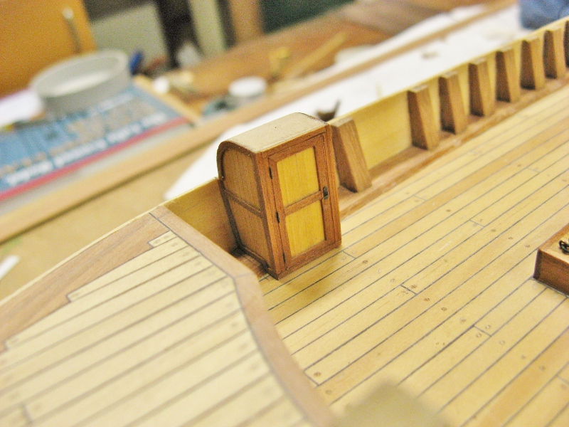
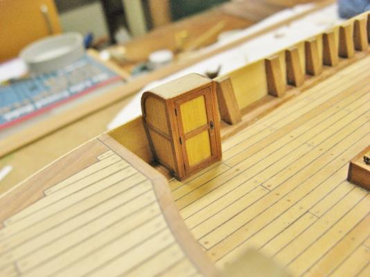
For the moment, I have been working on the forward section, completing the structure over the starboard hatch/companionway (I have no idea of its correct name). I shaped a block of MDF then covered it with veneers, and added some hinge pins and a handle to complete the look. The dimensions for the catheads are only best guess, the plans are a little vague. Does anyone have information regarding the diameter and width of the sheaves in catheads, also the length of the slots to accommodate them? The out board end of the catheads are 300mm (12") square. Grant.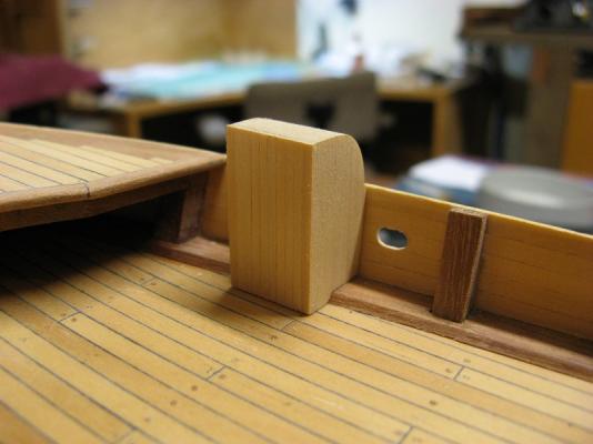

-
Harriet McGregor by Boccherini
Boccherini replied to Boccherini's topic in - Build logs for subjects built 1851 - 1900
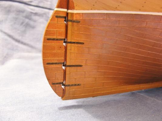
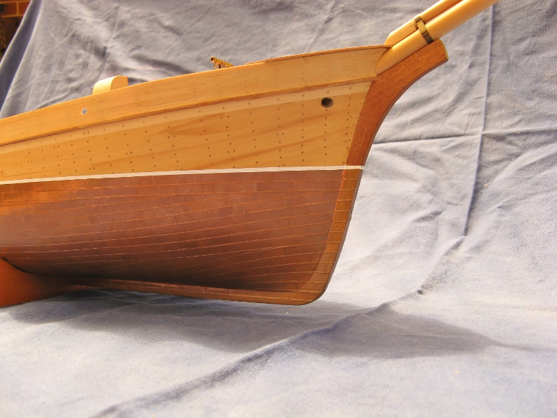
Nenad, I used thin copper sheet, which was cut into strips, then into the individual pieces. They have been attached to the hull with contact cement. Grant. -
Harriet McGregor by Boccherini
Boccherini replied to Boccherini's topic in - Build logs for subjects built 1851 - 1900
Daniel, thanks for taking the time to comment. The bulwark stanchions have already been pared back (with a chisel) as far as practicable without having to remove the waterway. It's not ideal, but I can live with it. Grant. -
Harriet McGregor by Boccherini
Boccherini replied to Boccherini's topic in - Build logs for subjects built 1851 - 1900
Floyd & Michael, thanks for your comments. John, thanks for the additional historical notes. Grant. -
Harriet McGregor by Boccherini
Boccherini replied to Boccherini's topic in - Build logs for subjects built 1851 - 1900
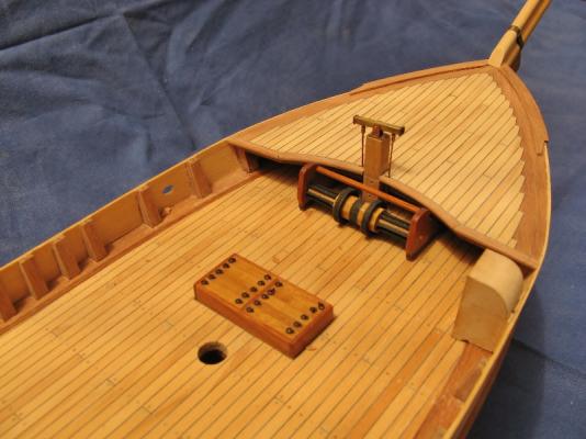
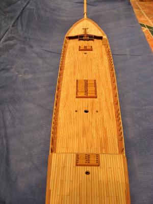
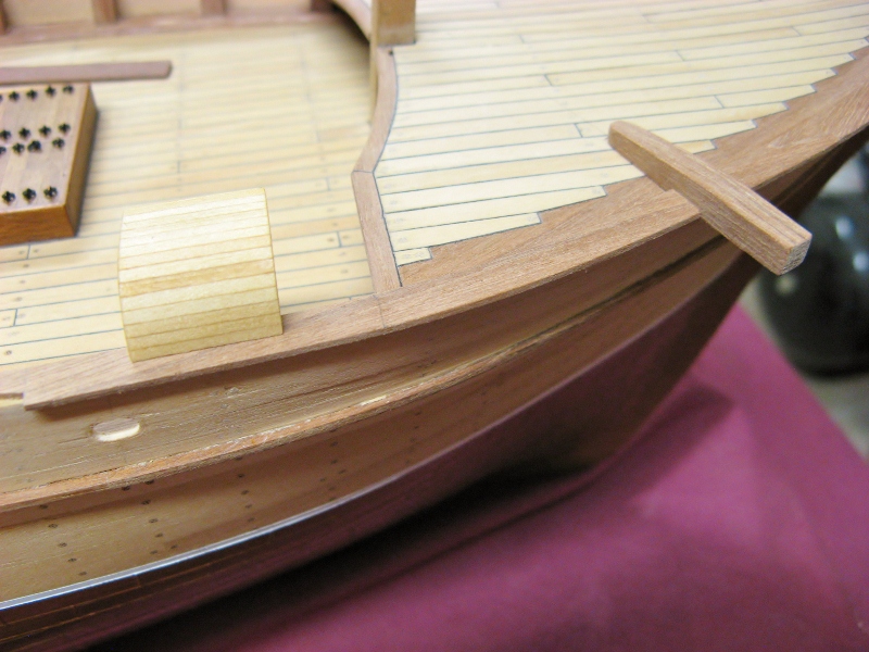
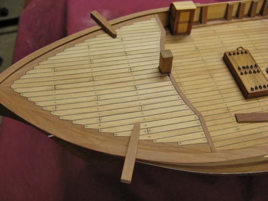
Gentlemen, thank you for your interest and encouragement. Rudolf, the frame extensions that form the stanchions are closer together in the areas where the standing rigging is attached to the hull via the chain plates. The extra stanchions were necessary to strengthen the bulwarks to take the strain of the rigging. This information came from the "Plank On Frame" books by Harold Underhill. There is no topgallant rail shown on the plan, the pin rail is shown below the rail. Floyd, joggling the planks is just an exercise in patient cutting and trimming (with a scalpel) until it comes together. The end of the joggled plank is supposed to be half of its width, the angled side is a line drawn from that mid point to where the plank cuts the edge of the margin plank (my apologies for the explanation, it is badly described, I hope you get the idea). The margin plank was joggled after it was fixed in place. I followed the method set out in the "Plank on Frame" books, which I believe was actual practice. Deck planking is pine, the hatch coamings are jarrah, (a local hard wood) hatch boards are walnut. Yes, the windlass is scratch built. With regards to her history, I know very little. Built in the 1860's (I think), she famously ran to a schedule like a train timetable for 25 years between Australia and England. Her end is unknown to me. Grant. -
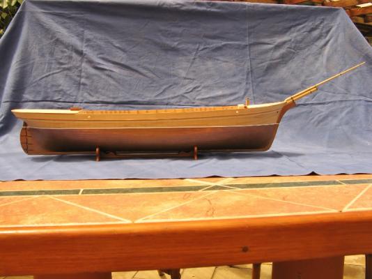
Having finally completed the Triton x-section, it's time to return to this, my first attempt at a plank on frame scratch build. It is the Tasmanian built barque Harriet McGregor from the plans by Harold Underhill, scale is 1:60. Originally started before Dry Dock Models was in operation, I lost interest in it due to the number of mistakes made in the earlier stages of construction that began to affect the build at the current point. The worst mistake: frame extensions above deck level should have been reduced in thickness prior to the waterway installation. I have done what I can to rectify this without pulling the waterways out (not practical), but will have to live with the consequences and work around the problem, hoping other small details will draw the eye from the larger inaccuracies. Having said all that, the model to date does bear a vague resemblance to the plans. Grant.