GTM
-
Posts
249 -
Joined
Content Type
Profiles
Forums
Gallery
Events
Everything posted by GTM
-
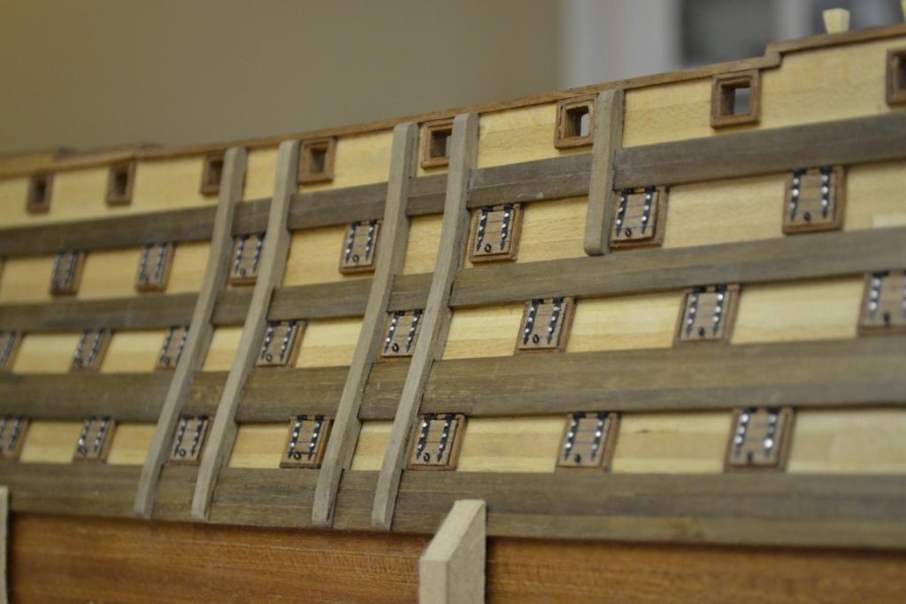
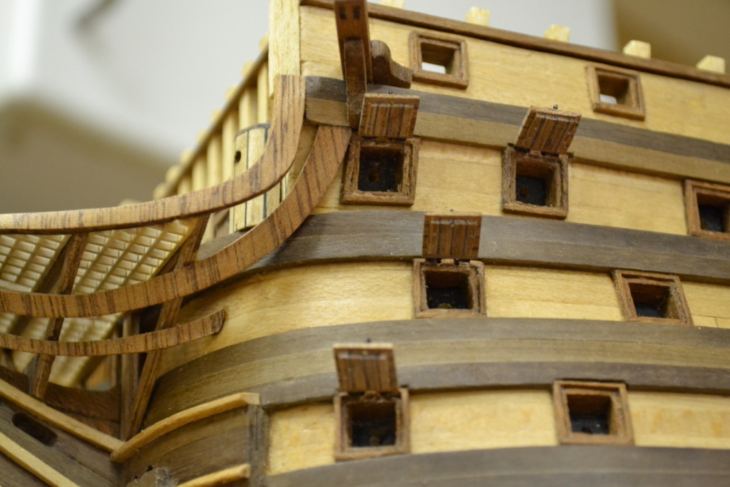
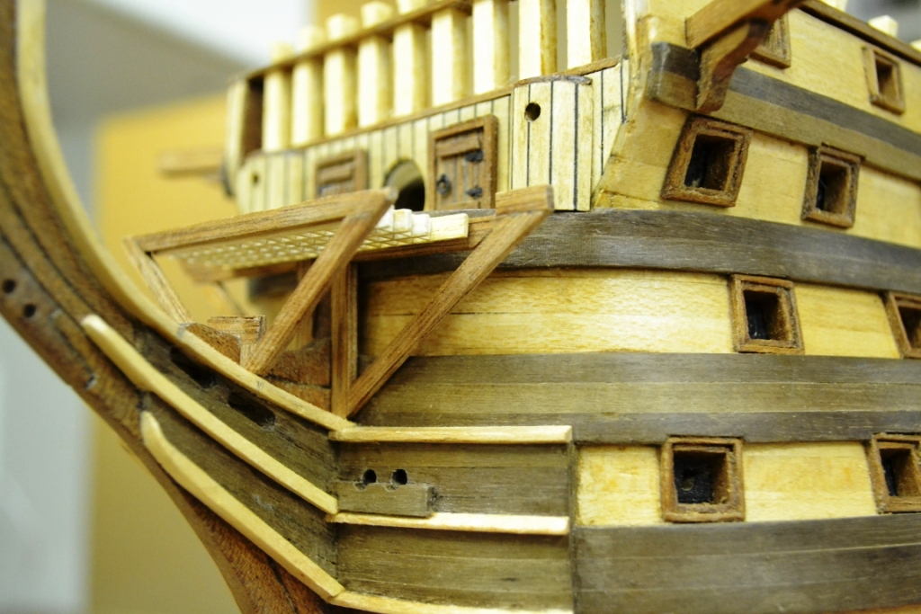
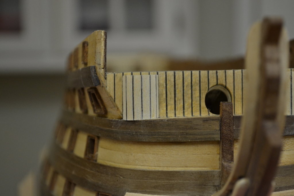
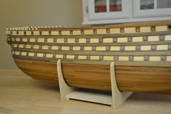
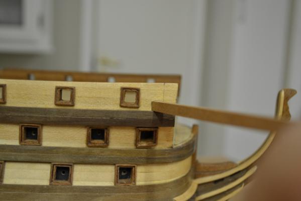
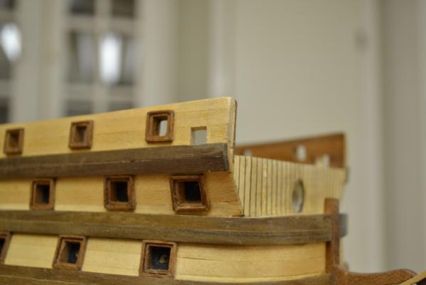
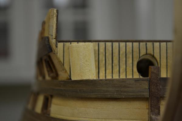
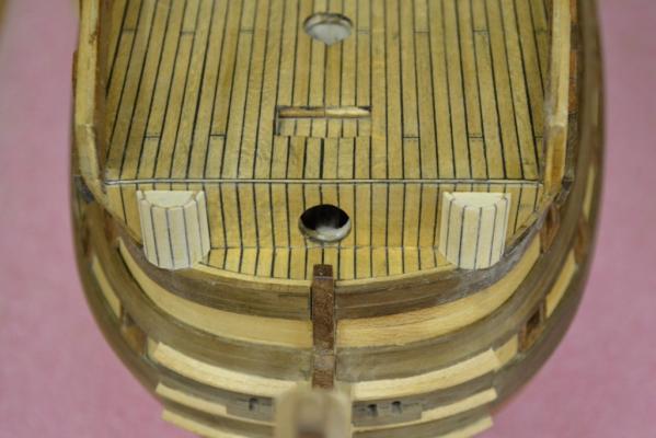
 Thank you all for the comments they are very welcome & appreciated .. Only an minor update today, I continued with the fenders and managed to install them on port side as well It seems pretty straight forward to install these but actually I find them a bit tricky. So underneath a few pictures of the procedure which I found useful for myself. I started with cutting all the needed strips in between the handrail & rubbing strakes Then I glued the top strip in place with CA Glue And I used this as the guideline to position/glue the strips individually in place and making sure to follow the curve of the hull in the process There’s quite a curve in the lower part of the fenders and to avoid too much trouble I decided to cut/glued a piece of scrap wood in place to follow this curve The shaping progress And here’s the final “waxed” result
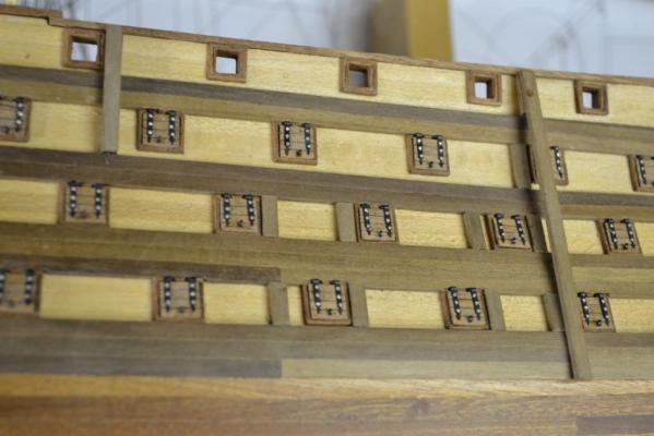

-
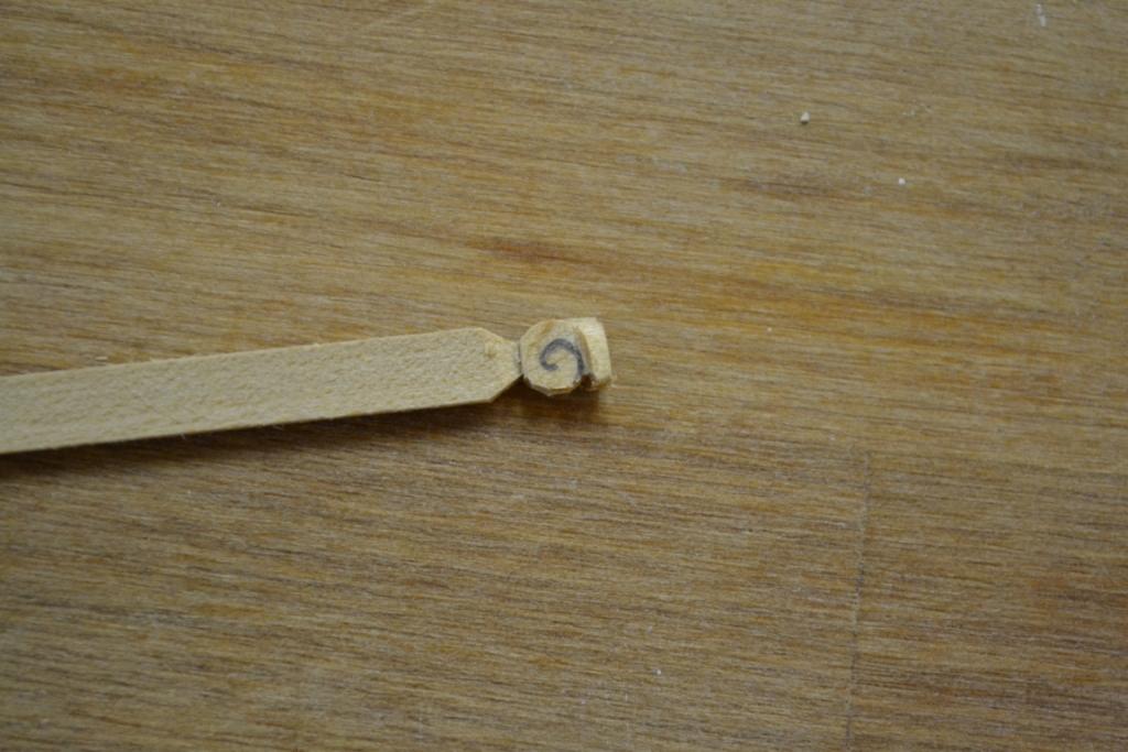
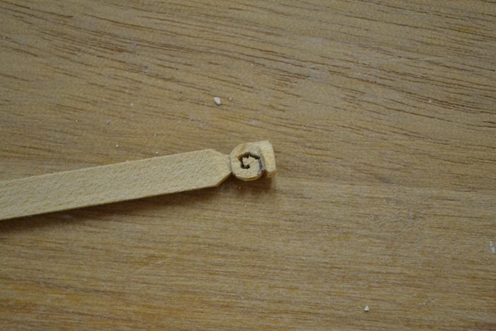
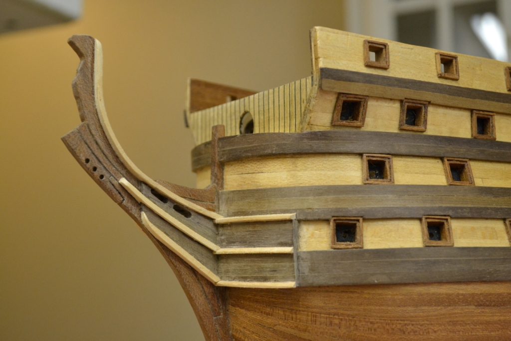
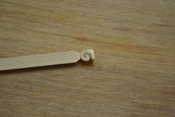
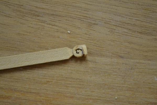
Today i really challenged my skills and started to carve “an minor ” detail to the stem.. As you might guess this is not an expertise I master so well, anyway, here are a few pictures how i ended up with the final result.. I used some scrap wood and started cutting roughly the shape and outlined a curl with an pencil.. I started drilling a few holes on the line from the middle (to prevent the wood from snapping) by using a 0.5 drill-bit and carved all the curves/lines with a No.10 scalpel blade. The result is not perfect but not too bad either, specially when considering that this is my very first carving. I polished the surface (as it was pretty rough after cutting) and the best results gave a narrow strip (1 mm) of sandpaper (grit 2000) ..and something completly different .., I placed all the fenders on starboard site

-
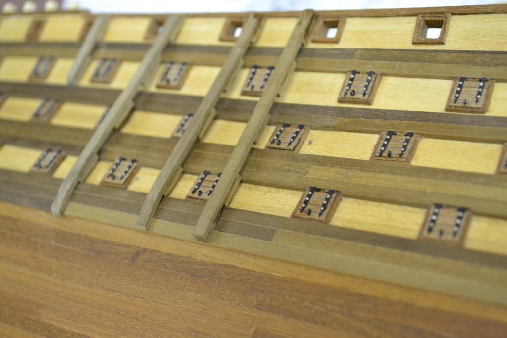
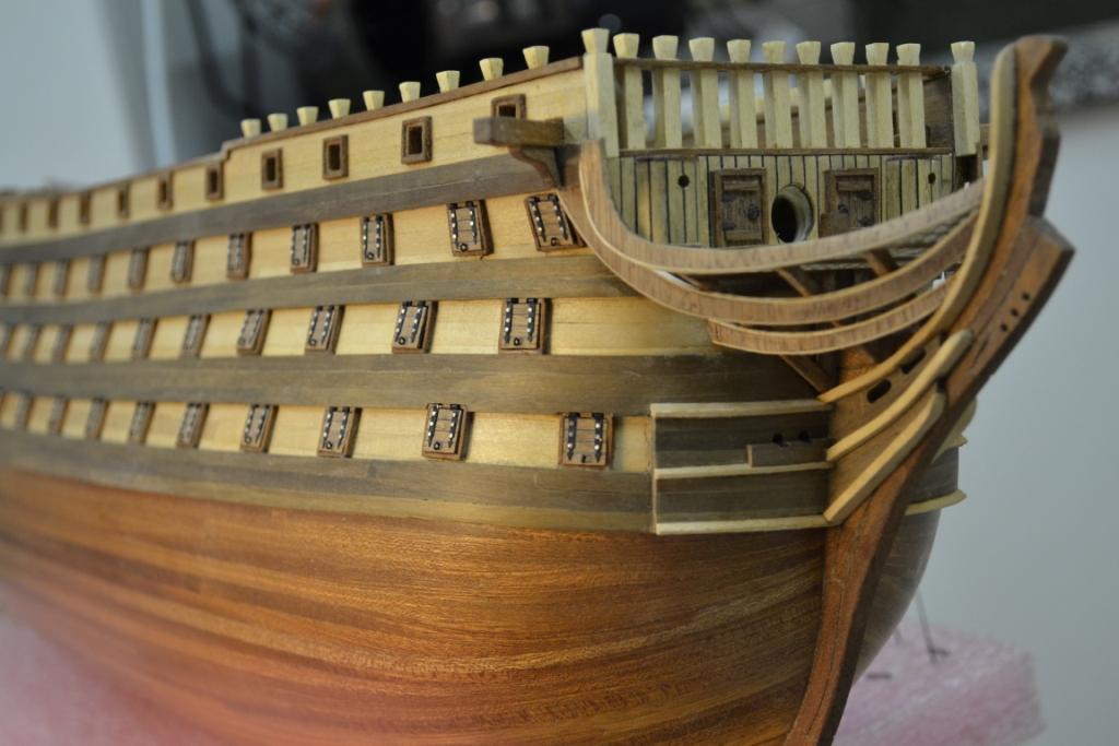
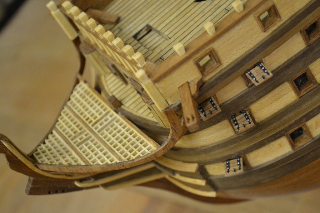
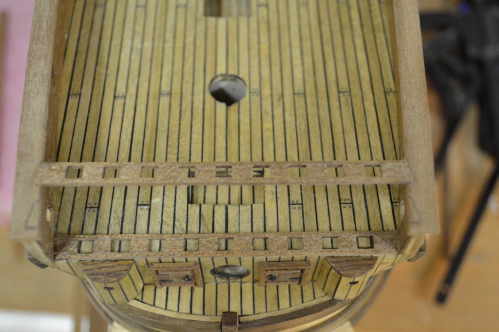
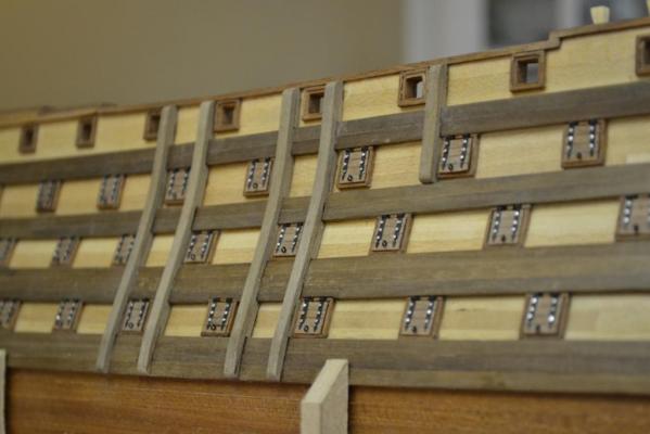
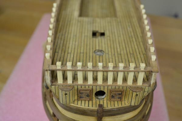
Yes ”finally” !!!... I have now also installed all the hatches on starboard side, here's the picture to prove it. So I have focus again on some other parts of the hull and started off with adding borders to the already installed rails. I think it gives a better visual impression and it also strengthen the rails. .. During installation of the hatches I found out that they were pretty vulnerable and break easily.. unfortunately I don’t believe these borders are that authentic, at least I haven’t seen it yet on the paintings/pictures of the ST

-
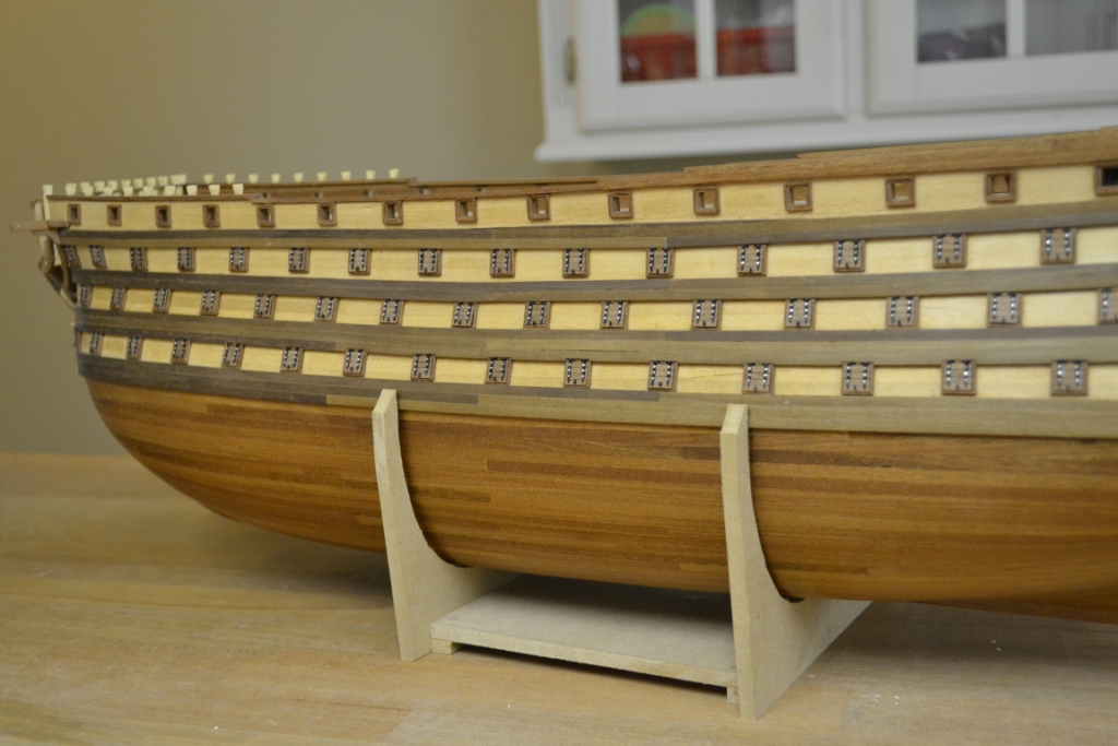
Thank you all for looking into the build and for all the positive comments/reactions. @ Daryl, you’re chalking technique looks great, I will certainly have that one in mind for my next build I had a busy November and didn't had so much time for the project, but somehow I managed to install all hatches on the port side So, .. only 52 hatches more to go..
-
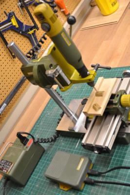
Hej Richard, I’m a lucky man and own both setups (the MF70 & the BFW 40/E and the table setup as shown by MIJ) So hereby my findings for both setups.. I started off with the MF70 and I’m very, very satisfied with this product Pro. -It comes with an compound table and the “head” also moves down & up via an spindle and it is good for accurate router tasks. -It is also very good for small router bits and harder materials as the speed can varied between 5.000 - 20.000 rpm -Collets and a three-jaw drill chuck can be used -Is a small machine Con. -The “spindles” on the compound table (200x70mm) are small and therefore I use the spindle itself for accurate movements and not the handles -It is a time consuming machine for drill tasks as the vertical movement only can be operated by an (small) spindle -It can’t be used for “tilted” drill/router tasks As for the other setup.. I was actually looking for an drill-press but instead my attention focused on this BFW 40/E setup (contains BFB 2000, KT 150 and BFW 40/E) .. Con. -The total setup is more expensive (but I must admit it is worth the extra money) -Needs a separate power supply -Less rpm’s than the MF70 (900-6.000 rpm) -Only collets can be used Pro. -The compound table (200x200mm) can be bought separately/later, the spindles are more accurate, can move very fast and the handles are usable -The head can be tilted, so angled tasks are no problem -The setup is Multi-functional (via an lever the head can be switched into a “router/static” or “drill-press/lever” mode) -The motor-unit (BFW 40/E) is very, very, very quiet… -It can also handle “big” work pieces
-
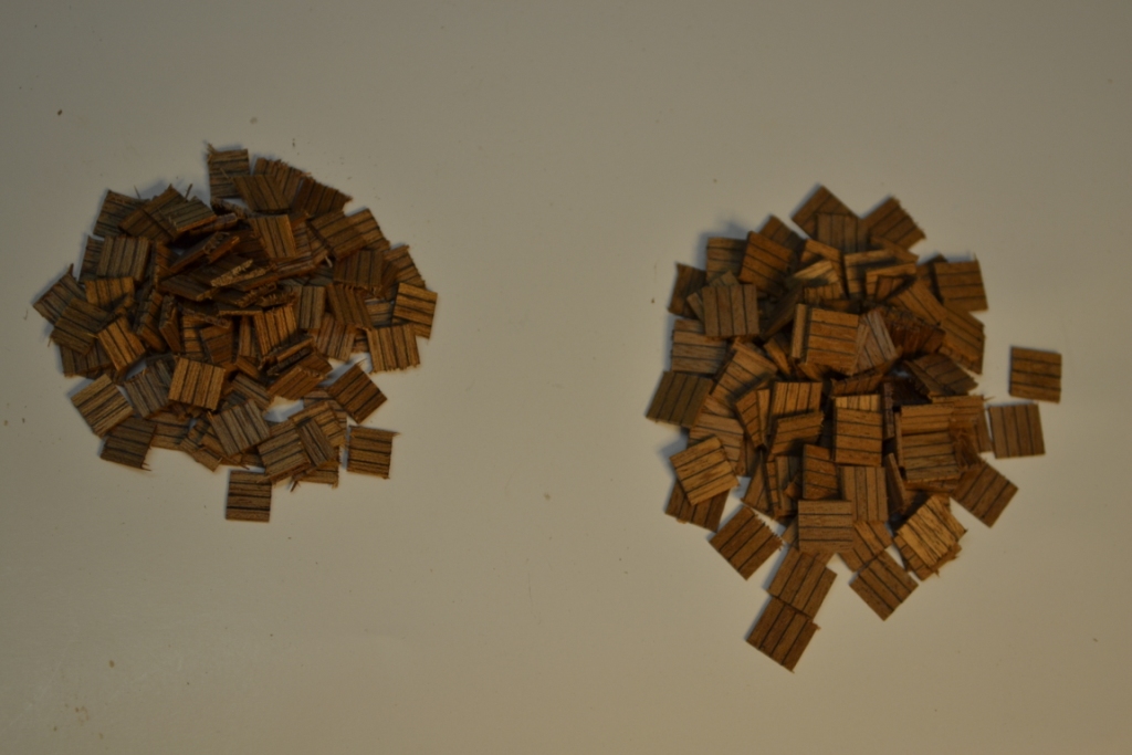
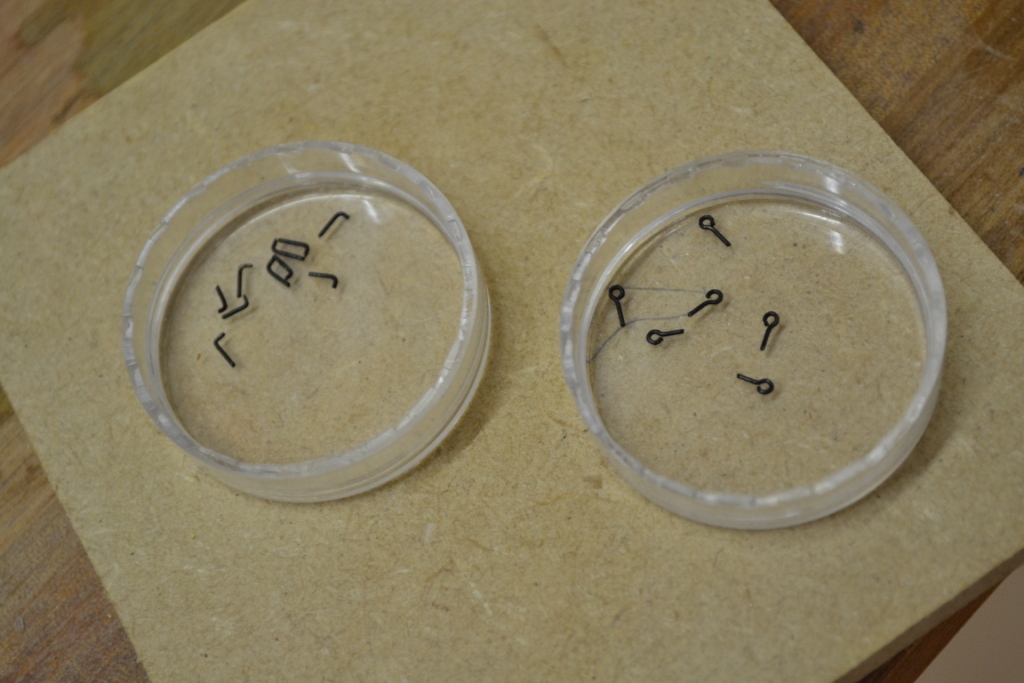
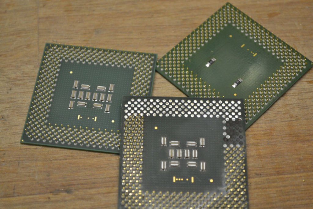
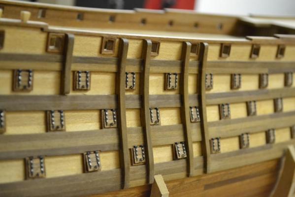
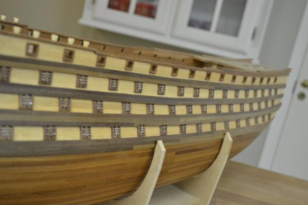
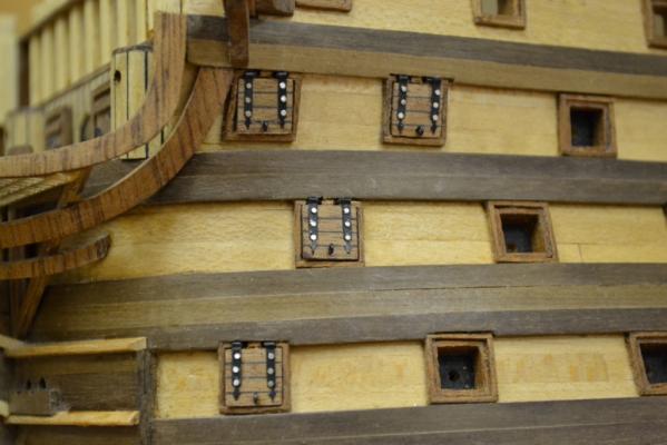
Wow.. Thank you all for the reactions and for following this build .. it is inspiring and it is really appreciated .. After having blackened all the hinges, I continued with the hatches, they are cut out of a block of sandwiched mahogany fineer & black paper. I only made a few eyes and some “L” shaped hooks at this stage to see if my theory will hold. As for the nails.. A few “old processors” (socket 370) were sold on ebay for a couple of euro’s (they are obviously getting sold out there for recycling of their gold) Anyway I will have enough nails for several future builds to come.. Today I made a serie of 4 hatches (to time the “production line). The hatches themselves are pretty quick to make, but it takes time to install them. I need to fine tune each hatch so it will fit inside the frame and “cut out” the frames so the hinges and the “L hooks” can be installed So here’s the result .. (only a 100 left to build..)


-
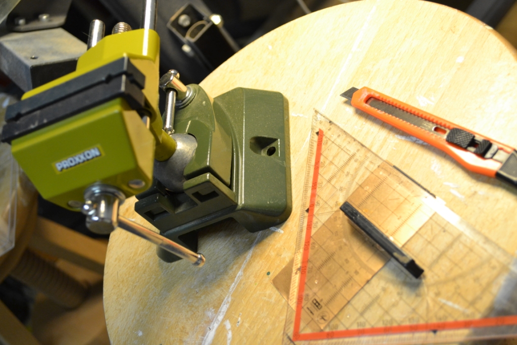
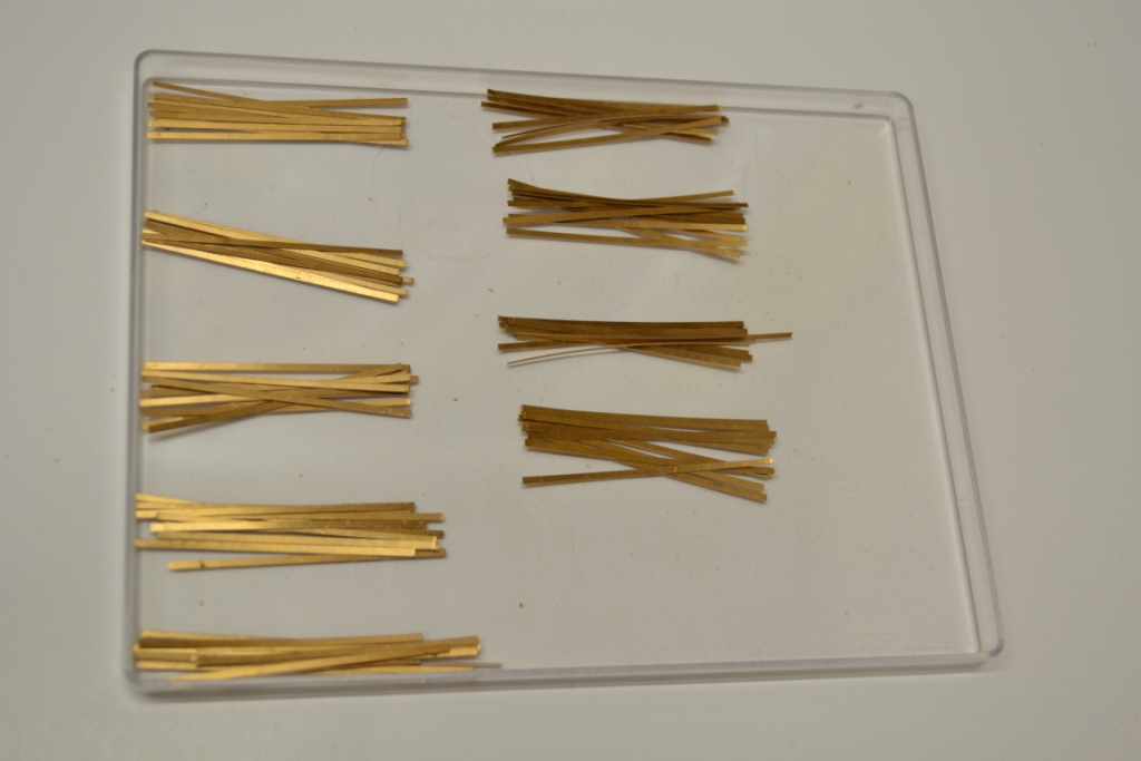
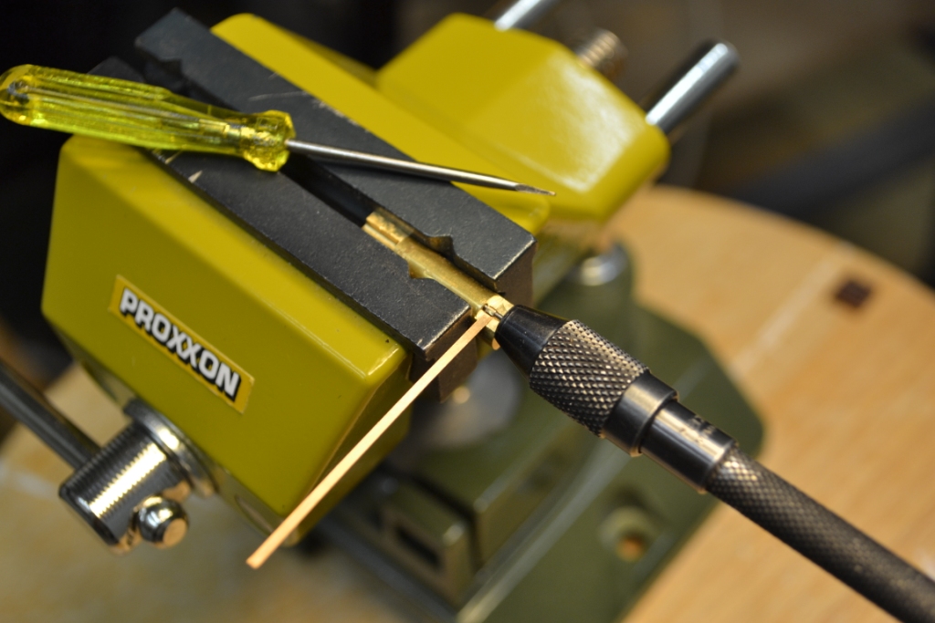
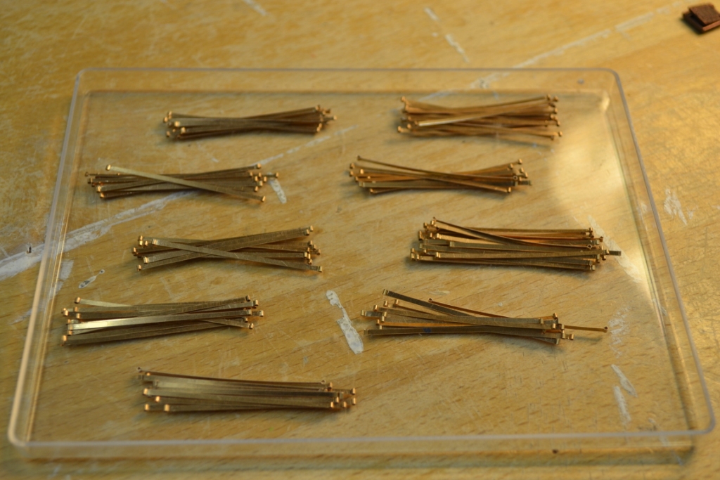
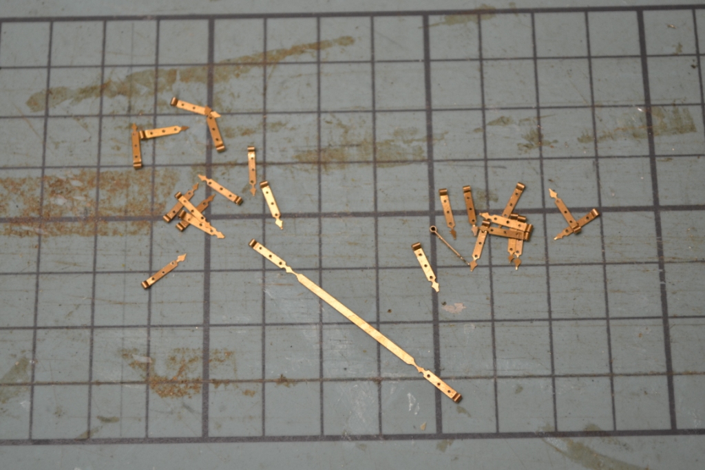
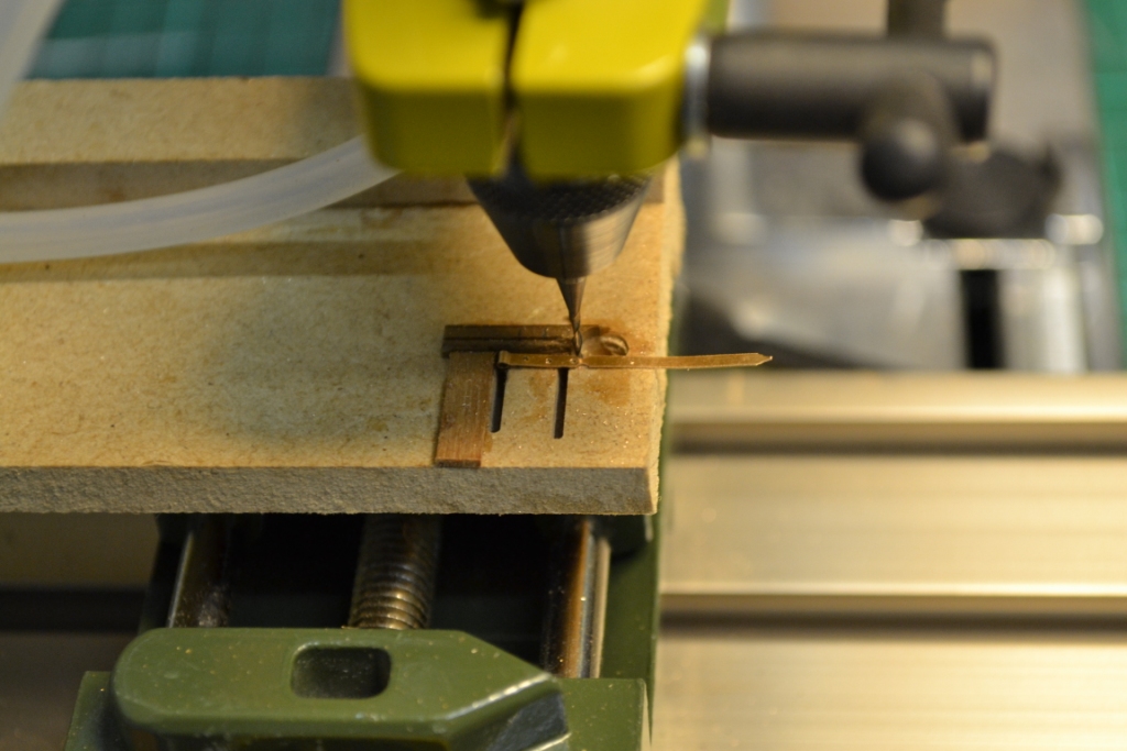
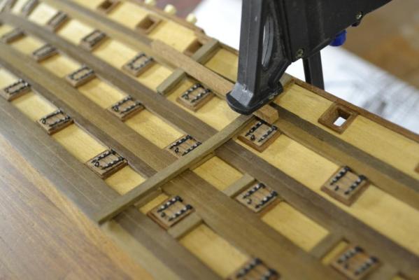
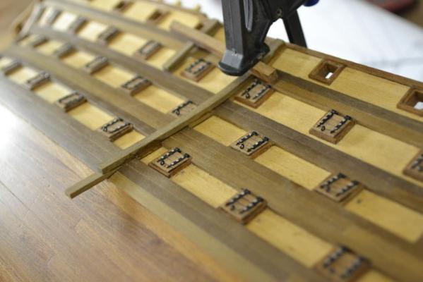
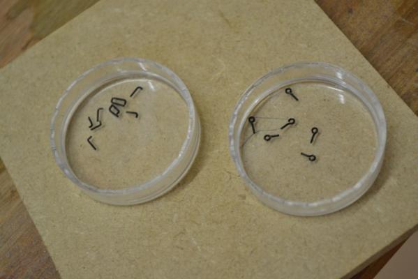
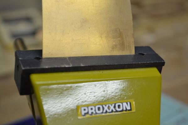
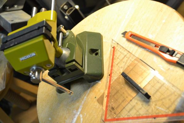
Well i guess there’s no way around it .. It is about here where I need the 104 hatches for the cannon ports so I better start up the production line for it .. The fist hurtle is to create the 208 hinges for them.. I started with the easy part: cutting up app. 110 strips of a 0,2mm thick copper sheet. For this I use a sharp cutting-blade, an ruler and a drill-bit which I use as the guideline for the wide of the stripes. I cut gently across the sheet with the knife and use (in this case) a vice and “clamp” the markup line. When now bending the sheet carefully back and forth it will eventually break on the cutting line. The result will be perfectly cut strips. The next task was also not so bad either. I already had thought about this part and came up with the idea to use this “special” jig for bending the eyes of the hinges See also this topic for explanation and how to create it LINK After all this I drilled all the holes by using a very basic jig. And after brainstorming for a while I came up with the idea to use a 1 & 3mm router-bit, (and again) a basic jig for all the “nice” curves to finish off the hinges. Not all of them are that perfect but hopefully I made enough.


-
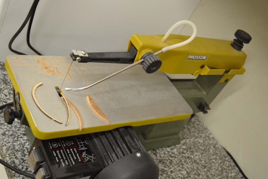
It is called ”DSH” from the manufacturer Proxxon. I think it is a good machine, it is running smooth and is not as noisy as i thought it would be..
-
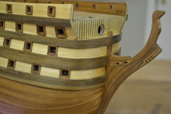
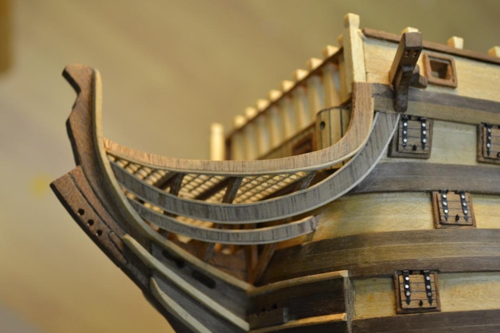
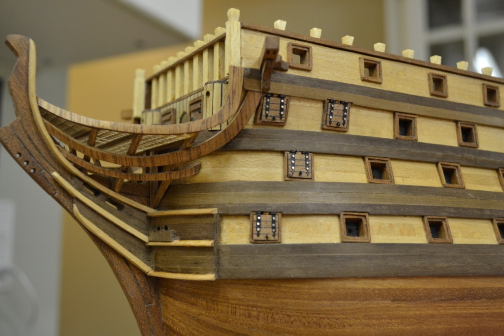
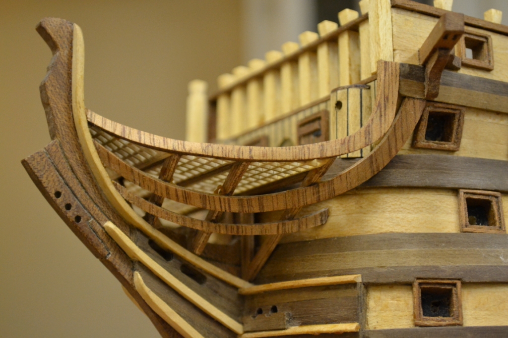
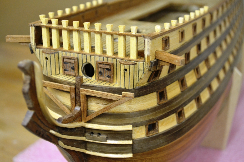
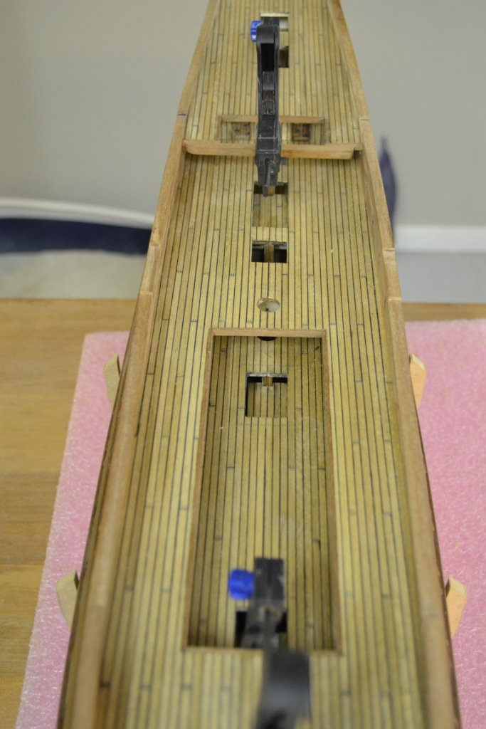
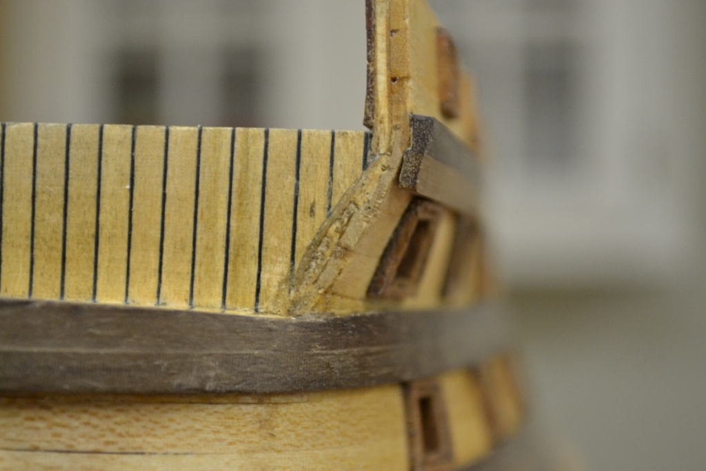
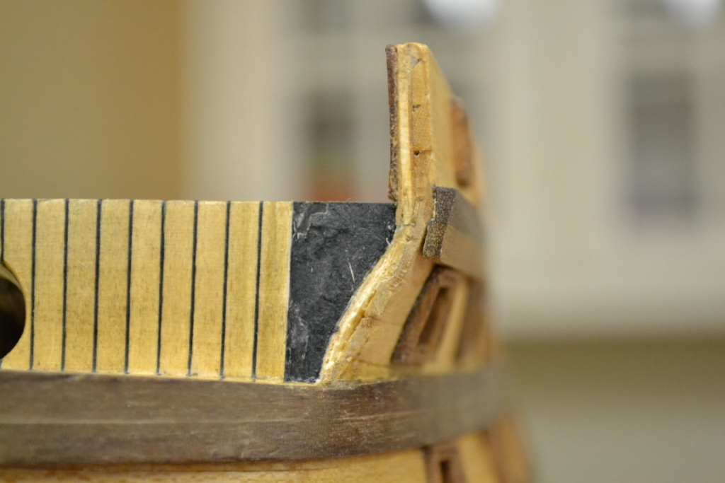
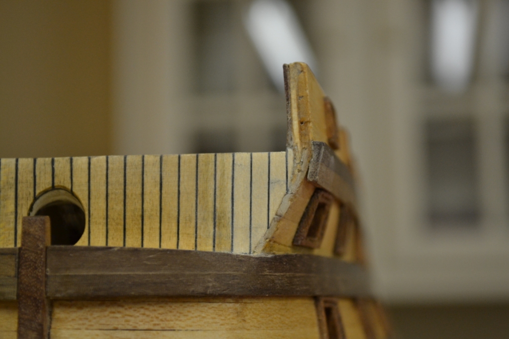
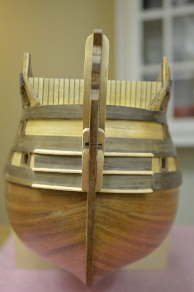
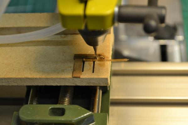
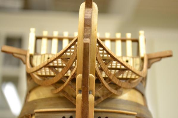
Thanks everybody for dropping by and all the kind words The next step, ”Rails” this was going to be a bit more tricky. These are not straight and the gratings and frames are determining the arc, so again I decided to test my skills on the jigsaw.. But this time I used my latest investment. TaaDaa!this is it I decided to copy the rails provided and use these as the basic shape with the intensions to “fine tune” them to the final arc and length needed. I also thought a bit about the wood grain direction.. My first thought was “vertical” as the rails on the model bend mostly in this direction so I didn’t had to shape them into their position. But on the other hand I knew that choosing this direction the wood also would/could easily snap ..I decided for “vertical” anyway and see how it goes.. Even dough the new tool does its job very well it is still not as easy as I thought it would be.. So a lot of sanding helped to get the "straight line" end result The instructions/drawings doesn’t really show where the starting positions of the rails are located:-- I decided to use the most upper strake as the start position for the top rail, the second rail just besides the first gun frame and the davit bracket and the 3th rail “as best as possible” To avoid too much stress on the top rail I shaped the Samson post with an angle. I must admit that some of the rails have snapped (some even several times) during installation.. Eventually I managed to have all rails in place and I covered all the break lines with glue and sawdust.. Enjoy ....


-
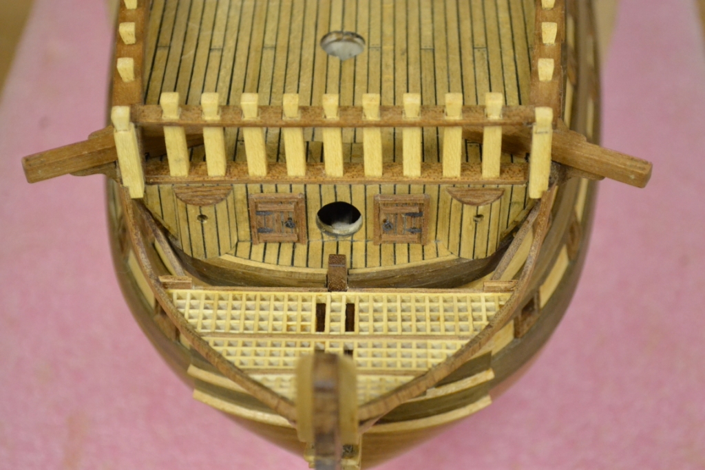
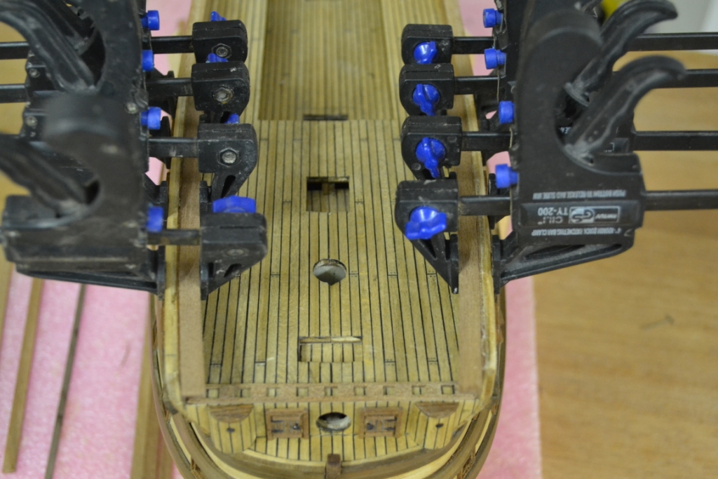
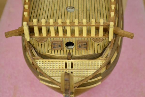
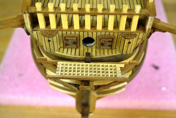
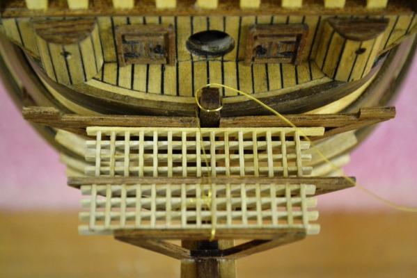
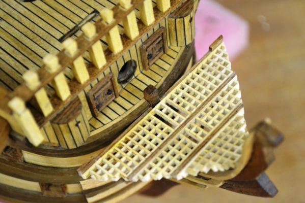
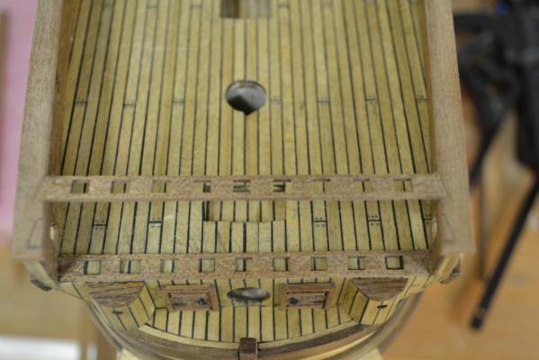
..Thank you all for the comments & likes.. as always they are very welcome. So continuing with mounting the frames onto the stem and making sure the first ones were positioned correctly & straight To make sure the distance between the frames also were correct I used the gratings as a distance guide .. by the way i made wooden "davit brackets".. This way it was much easier to make them a 100% fit (the supplied ones where made of metal) so i ended up with some modifications on the davits anyway After having positioned all the frames I glued the gratings in place and shaped/sanded them so the rails will have maximum contact later on


-
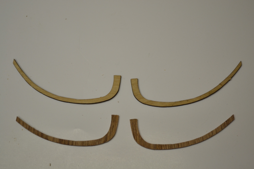
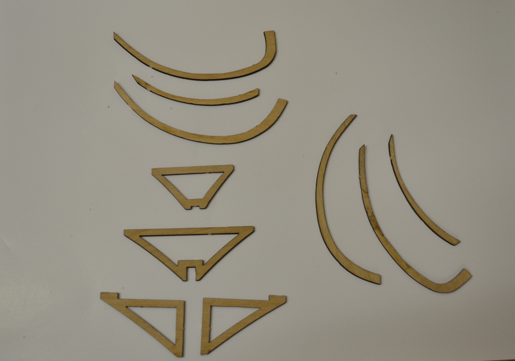
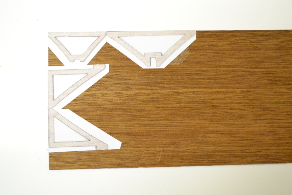
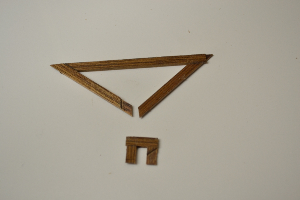
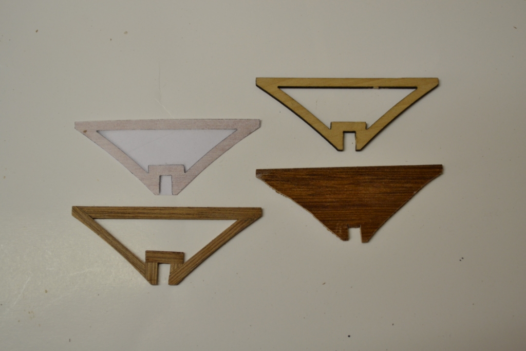
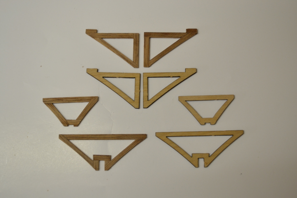
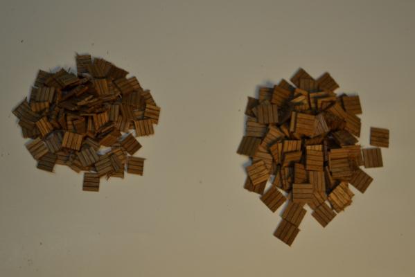
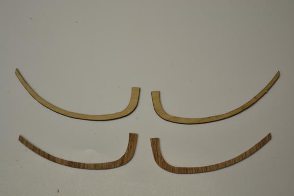
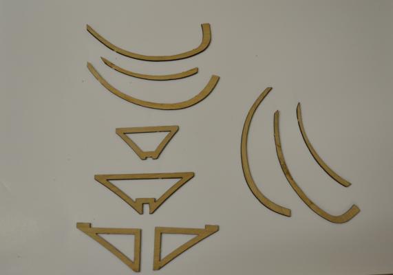
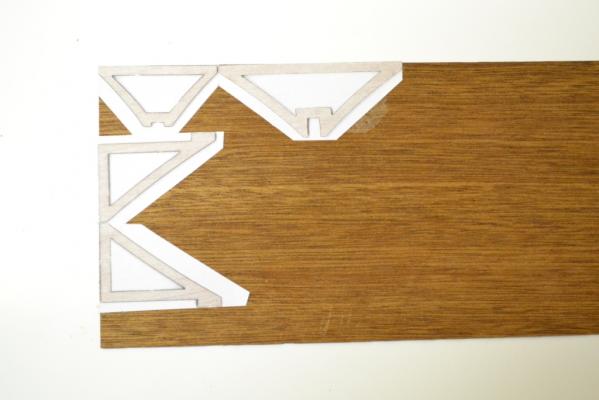
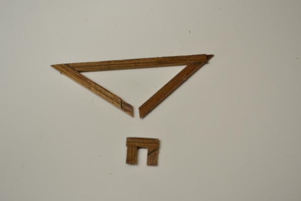
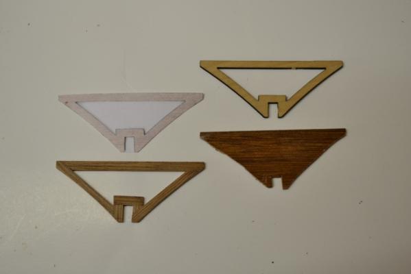
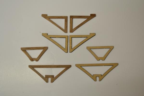
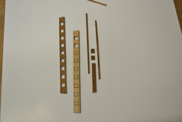
Continuing with the Davits, and I made them as suggested by the kit without any modification I decided to continue with the bow and started to look at the frames and rails in this section The provided parts are laser cut & are basically OK, ..but they are made of plywood.. so I decided to see if I could do it better The first attempt I did was to glue a photo copy the parts on a sheet of mahogany and use a jigsaw to cut them out. Probably because of my jigsaw skills but they turned out just terrible.. So I did a second attempt where I used 4mm strips of mahogany and glued them together with a “half & half” connection at the corners to strengthen the construction (I don’t know what this technique is called) I hope the picture is clear enough to show it .. Here’s the comparison between the different versions I made and the original one And here’s as a comparison "all the frames" .. so far so good ..
-
Thank you guys for the encouraging words I learned from it and i will leave them as they are . .. I certainly will camouflage the worst with coiled ropes ..
-
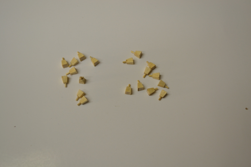
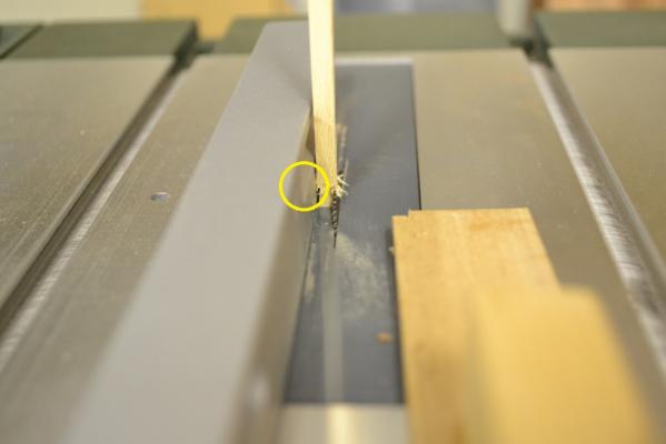
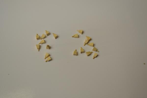
Thank you Mick & Tom for the compliments , it is as always appreciated But they are not so perfect as they seem.. Especially a closer (macro picture) will show that not all of them have the same angle on all sides I think I made the following mistake: I tried to make them as uniform as possible by using my table saw adjusted to 12 degrees. Which was not a bad idea, but by not removing the shavings after cutting a particular side it caused (slightly) different angles on all the other sides .. This I didn’t noticed .. instead i learned from it
-
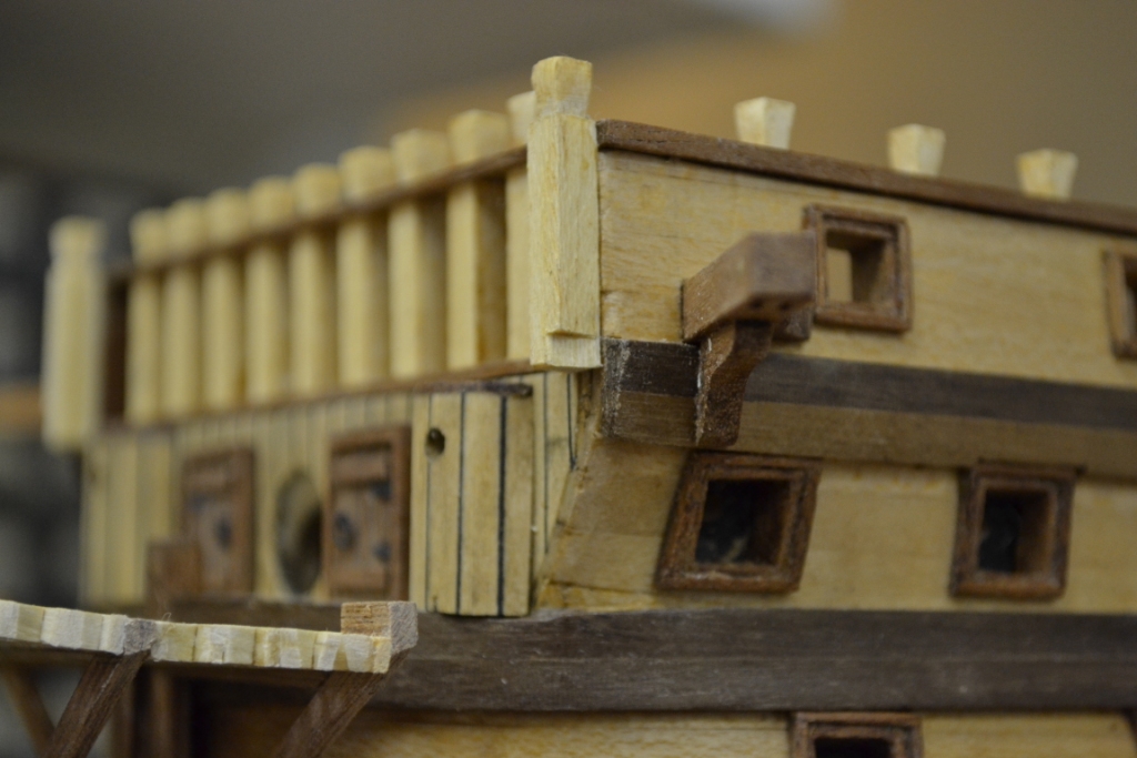
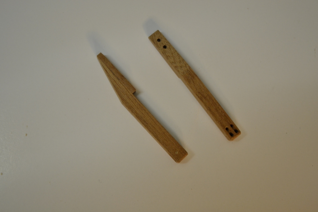
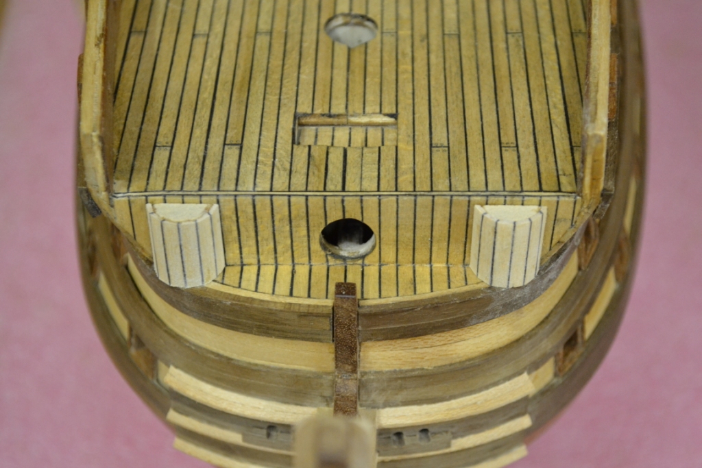
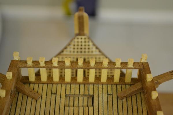
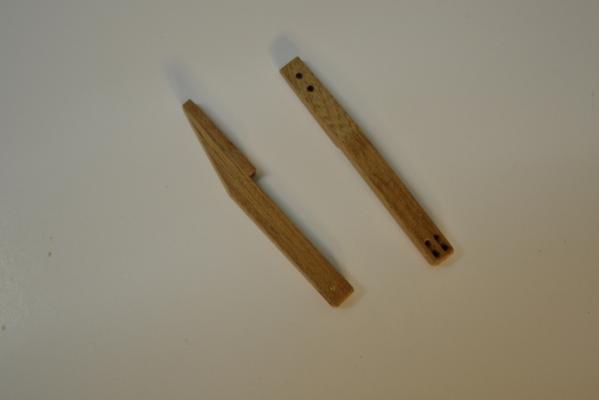
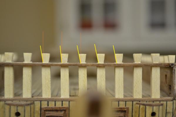
Continuing with the Samson posts. I decided to redo the bow waterway and bow limber board with mahogany wood cut out of a 1,5 mm sheet And bend the side limber boards into the curved shape of the hull before gluing them into position After this I fitted the bow limber board And manufactured the bow Samson posts as well as the side Samson posts Instead of just gluing them on the limber board I decided to add a Ø1mm “fixing stick” and drilled holes in the limber board . Hopefully this addition will keep them in place during the rest of the build I added all limber boards and the (so called ?) Waist coming & quarter deck Finial planks. Here’s the result so far.


-
Hej Anja, I (and I'm surely not the only one) now have patiently waited quite some time for updates.. Hopefully you have a reason and have not giving her up yet ?
-
Thank you Sjors & Randy for your kind words, it is really appriciated and Sjors i can really recomment the drill stand setup "it's like a dream.." Hej Demonborger I copied the cast metal gun port frames from the kit and it haven’t crossed my mind that these Gunport frames maybe stick out to much How do they look on your build, I asume you used the provided frames ? How far are you with the ST, are you considering a Build log on MSW as well ?
-
Thank you mick, yes “at last” I can focus on all the tiny details.. and not to forget the 104 gun port hatches ...
-
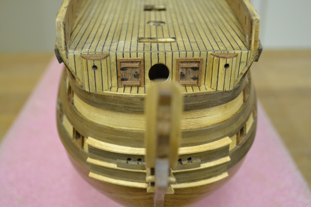
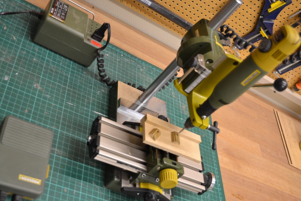
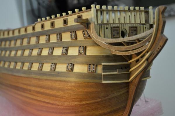
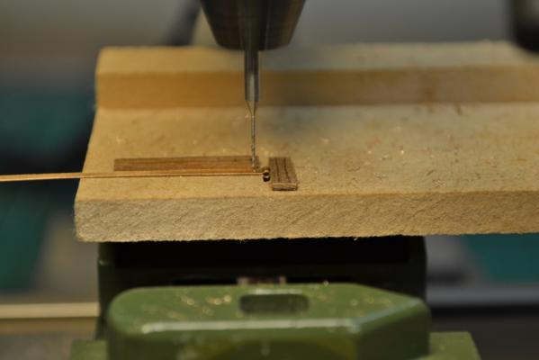
Continuing with the heads and a nice opportunity to tried out my newly arrived toy I decided to purchase a proxxon drill stand (MB200) with the compound table KT70 for my micromot 50/EF instead of buying a (proxxon) Bench drill press The main reason for this was that I also can use this setup when I need to drill in different angles (besides the fact that it is also a cheaper solution) Additionally I can now also use it for several other applications like milling and grinding as the micromot easily can vary speeds from 5000-20.000 rpm . I already had the optional food-switch for the micromot so I can also easily start the machine without removing my hands from the subject. So far I’m very pleased with the setup Underneath some pictures after the install of the heads & the doors (I allready made these doors earlier in the build) and opening up for the anchor davits in the bulwarks.


-
Thank you all, inspired by this little fix i'm moving ahead.. according to the instructions: The heads are glued into place.. As I found this a bit too basic I decided to modify them a bit before gluing them into place I like the consistency of the planks already and can't wait to glue them into place..

-
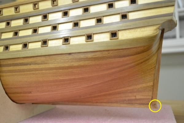
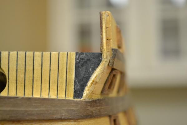
The finish between the deck and hull on the bow section annoyed me right from the beginning. Somehow I thought this was going to be covered by either a Samson post or an head rail later in the build. Today I found out that it actually will not be covered, so I made the decision to remove carefully a section of the deck strips And placed new ones with more precision Taa-daa !! the annoying feelings are gone and it didn’t even took that long to fix

-
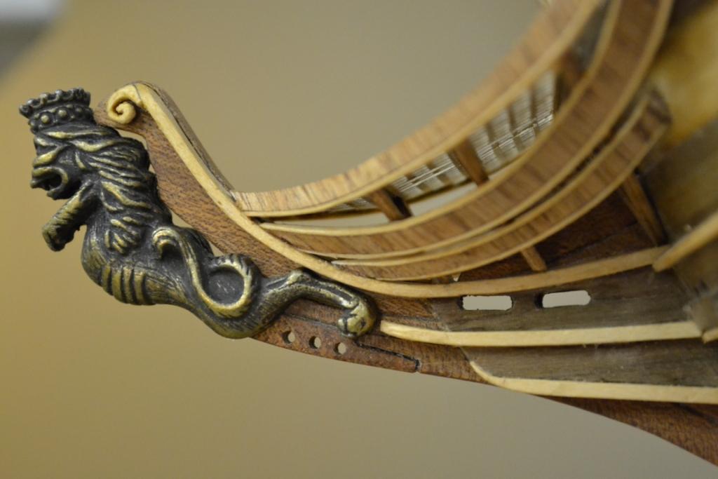
Thank you Ferit, your compliment is appreciated. I agree the figurehead is nicely done, of a good quality and it was indeed included in the kit .. So no sculpturing for me this time :mellow:
-
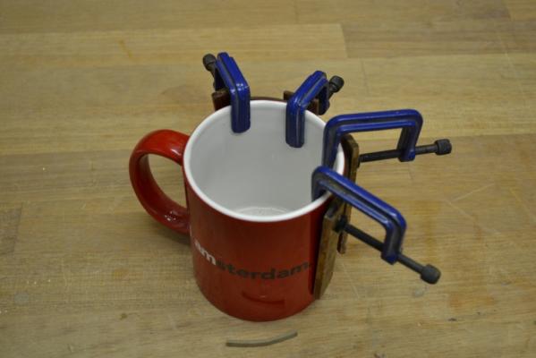
Thank you for your compliments guys it is really appreciated.. Yes indeed Mick you’re absolutely right.. As a matter of fact it took me ages to find this very advanced, "nicely shaped" and coloured cup-tool
-
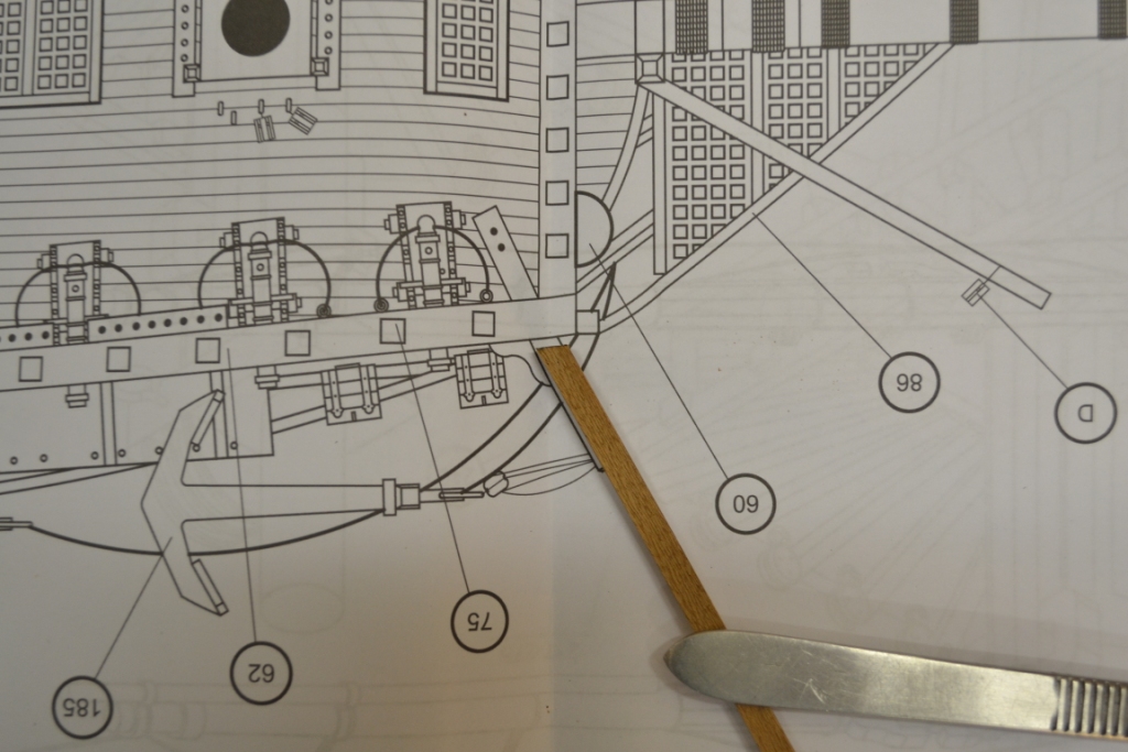
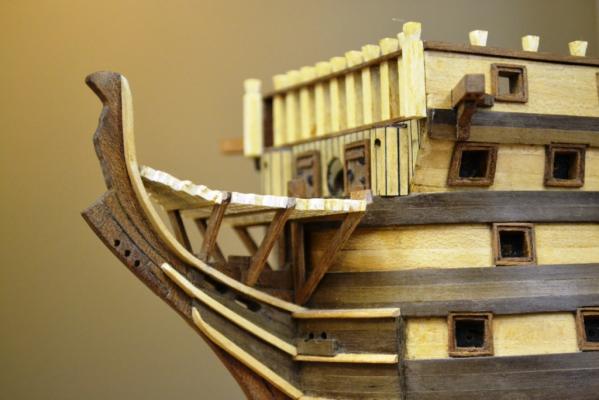
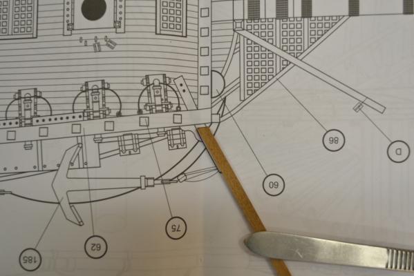
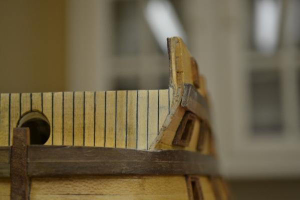
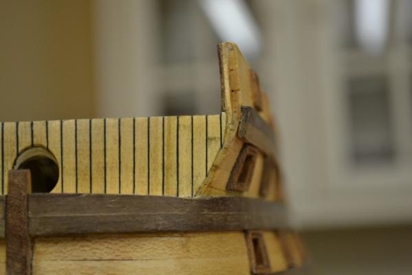
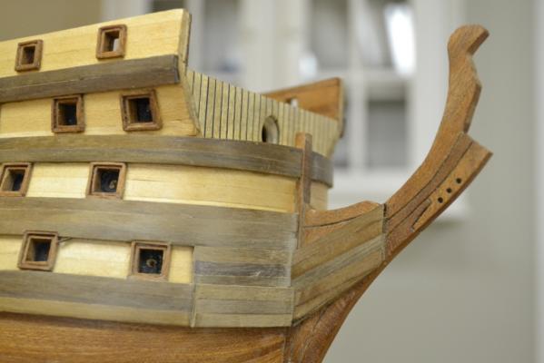
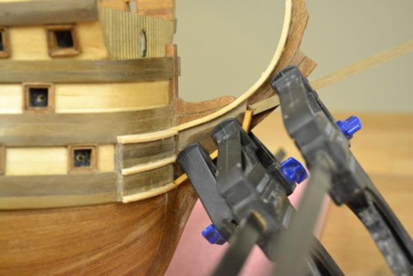
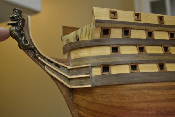
I continued with the battens. The first challenge I faced was to find a way to bend them with the curves of the bow. I found out that these walnut strips are not that easy to position without having them shaped first. The solution: I found a suitable coffee cup After having them soaked and dried on the coffee cup the rest was a piece of cake.. Bending the strips on the stem was a bit easier but I had to be a bit creative with the clamps… Note: I just copied the premade holes in the stem from the original, but these "original" holes were completly misplaced as i have positioned the strips & battens slightly different.. So I closed them again with scratch wood and re-positioned them after all battens & strips on both sides were glued in place.. Here’s the current state of the bow section with and without figurehead


-
Thank you Sjors & Ferit for your excellent advice on this, i will certainly do more effort to camouflage this fix as i still find it very eye catching..
-
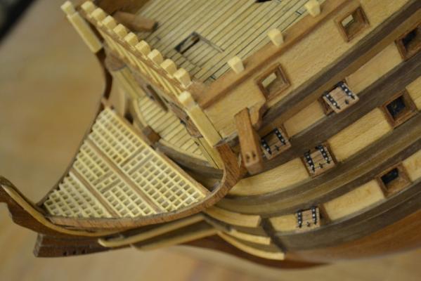
I found some time again and decided to spend it on the project I have now managed to place the keel. I’m now very pleased that I decided to replace the supplied plywood parts of the kit with Mahogany wood. I’m especially pleased with the bow section, even so knowing that some of it will disappear behind battens ? later on in the build.. Note: the last section was too short (unfortunatly I made all sections the same length as the supplied ones) so I had to extend the last one in the row ..not the best fix i have done so far but i didn't felt like exchanging the complete section..