HOLIDAY DONATION DRIVE - SUPPORT MSW - DO YOUR PART TO KEEP THIS GREAT FORUM GOING! (89 donations so far out of 49,000 members - C'mon guys!)
×

GTM
-
Posts
249 -
Joined
Content Type
Profiles
Forums
Gallery
Events
Everything posted by GTM
-
 Hej Sjors, I will post the missing pictures later this weekend ..It is not so easy to take pictures while using both hands to hold these tiny things..
 -
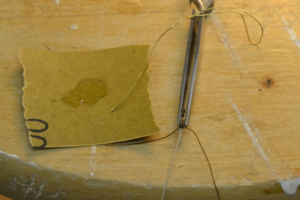
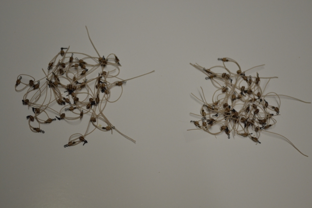
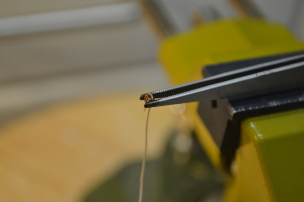
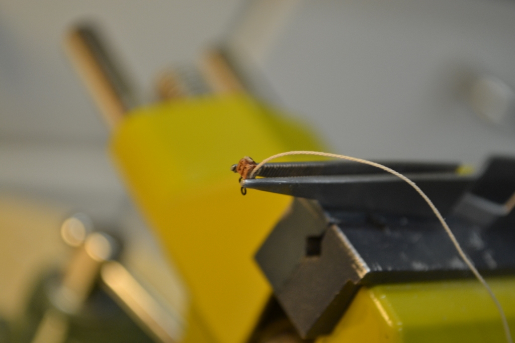
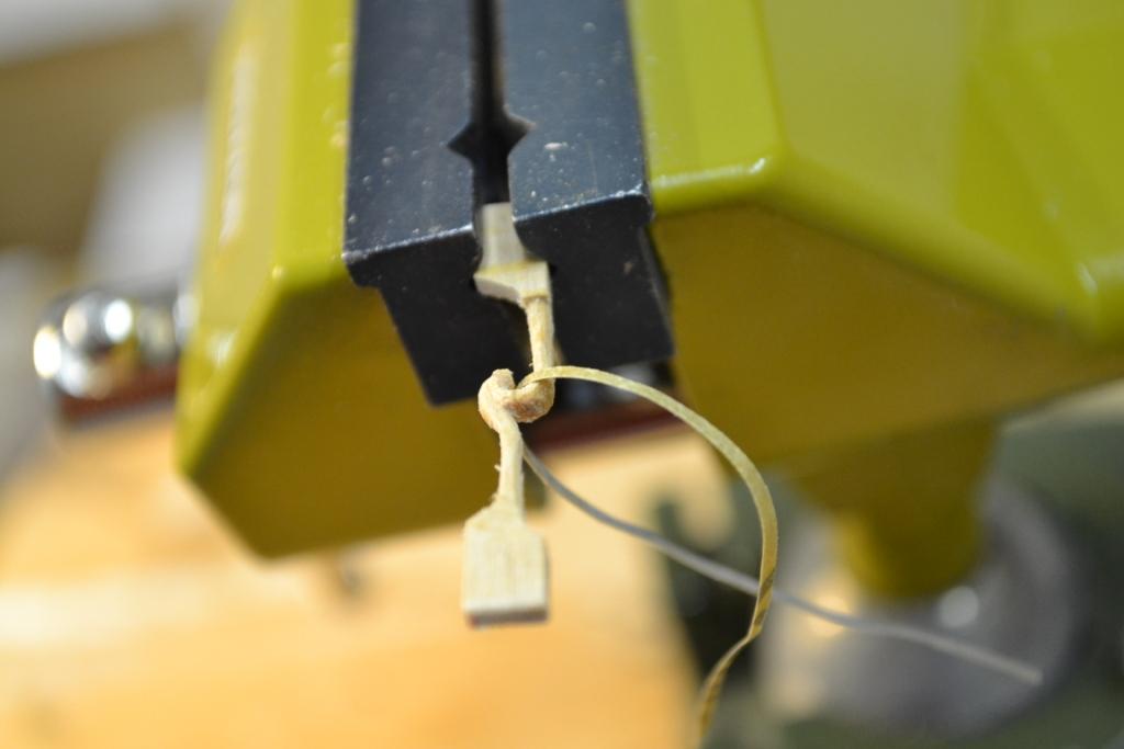
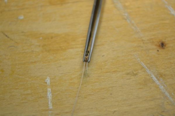
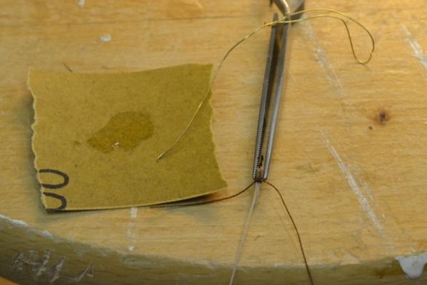
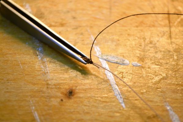
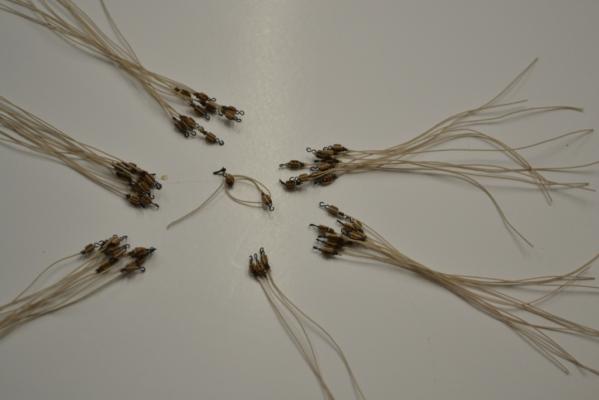
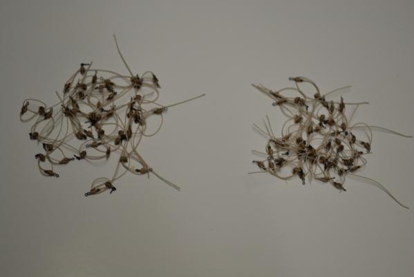
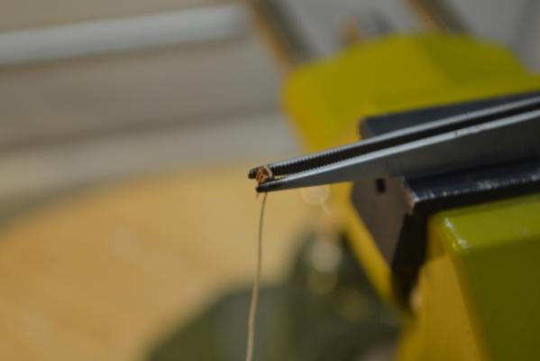
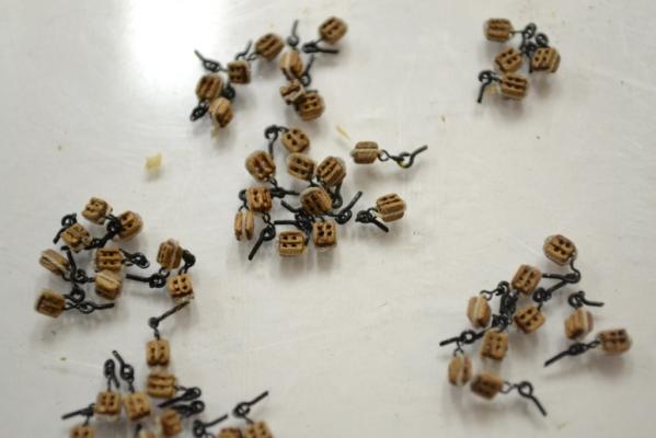
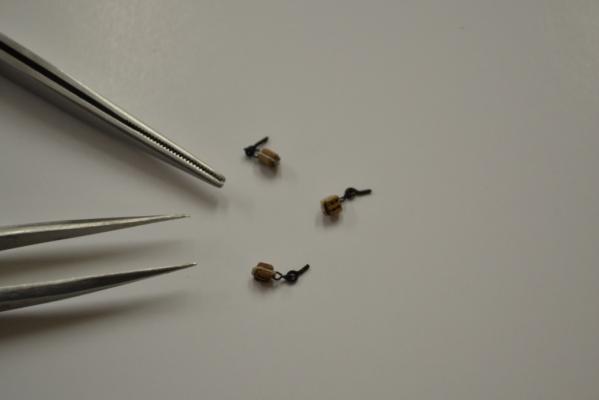
Continuing the production line with the single sheave block. I prepared all the ropes by cutting them to a 9 cm length. Wrapped it around the sheave including the eye and holding it in place with the “crossover tweezers”. Using brown sewing thread and a “normal” overhand knot to tighten the ends together. I lock the knot by dipping very thin CA on the knot. To prevent too much glue on the knot I started to use a piece of brass wire (made a small hook at one end) by dipping it in CA and carry it over onto the knot (and repeat the process as much as needed.) This method works very fine for me, when the tip becomes too thick (to much dried CA glue) I cut off the hook and make a new one. .. Easy, cheap, quick and efficient .. After wrapping the thread 2,5 times around I secure it again with CA glue, and cut off all ends.. The end result (left & right rigged) , the only thing remaining is to install them.. Taa-daa !!...
-
“I know", "I know”.. , I should not use SMS language on every keyboard.
-
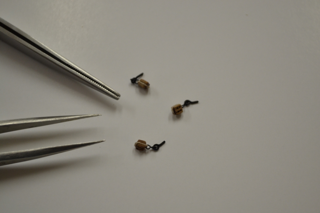
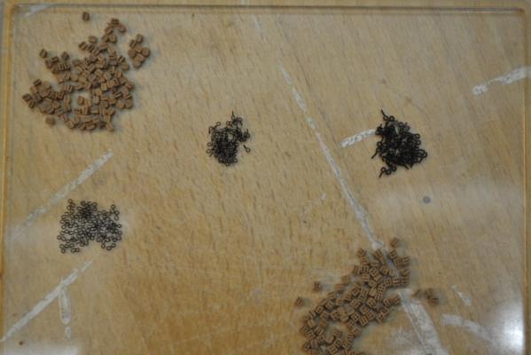
Some progress.. After this prototype rigging I started the "production line" this weekend. I made & blackened all eyes needed for the job, I decided to use 3 different eye types, when using these eyes the blocks are getting “angled" as i would like them to. I became extremely happy for my x-over-tweezers it really helped me to keep these small blocks under control while “attaching” the eyes to the blocks. "I cheated" by using (2) small drops of CA to fix the rope on the double sheaved block. all 54 of them..,so far so good..

-
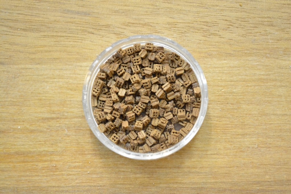
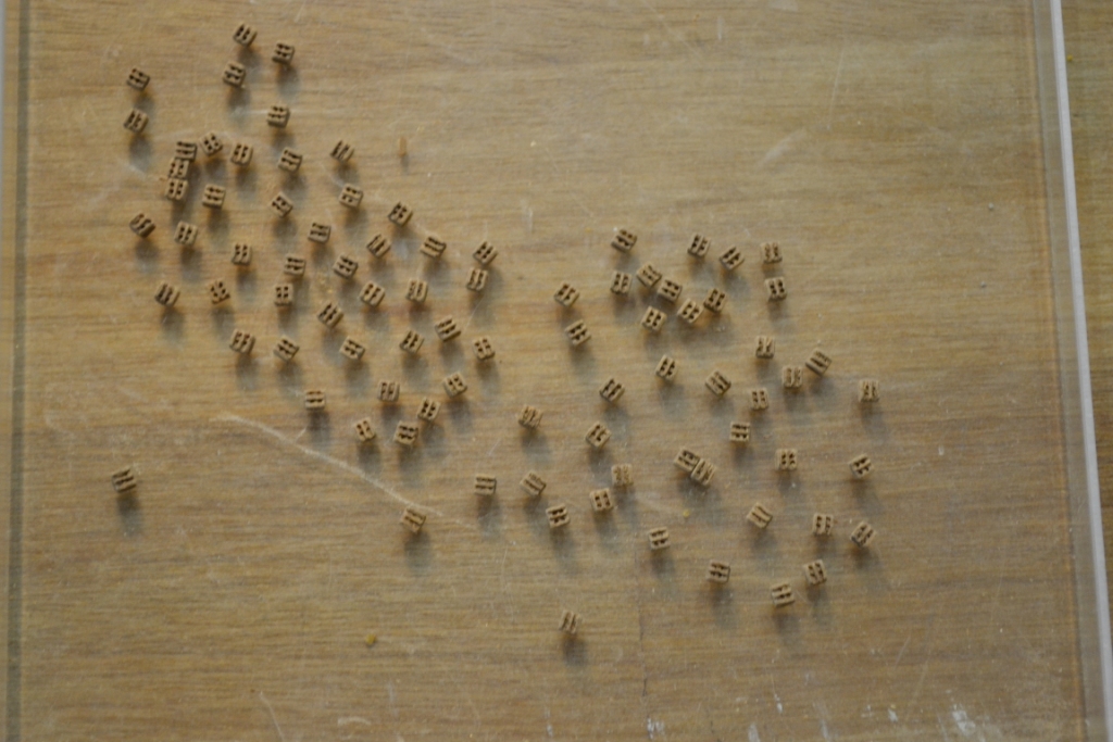
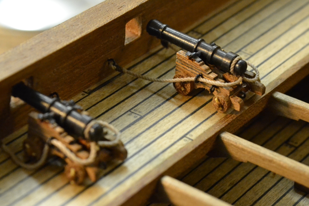
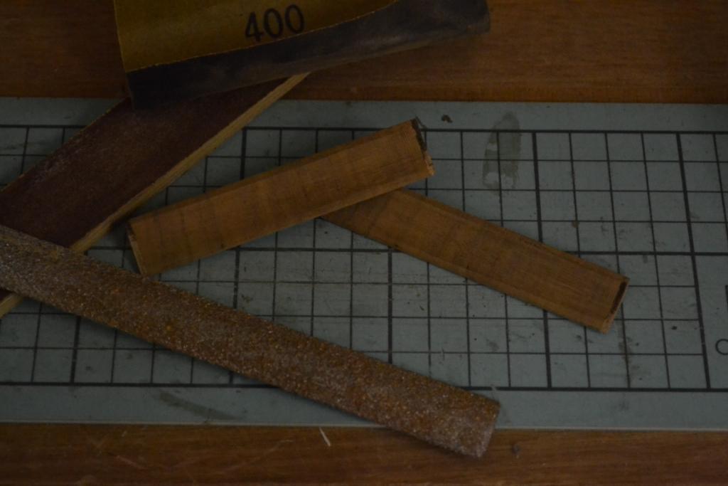
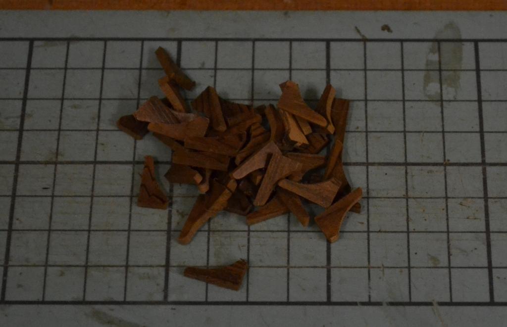
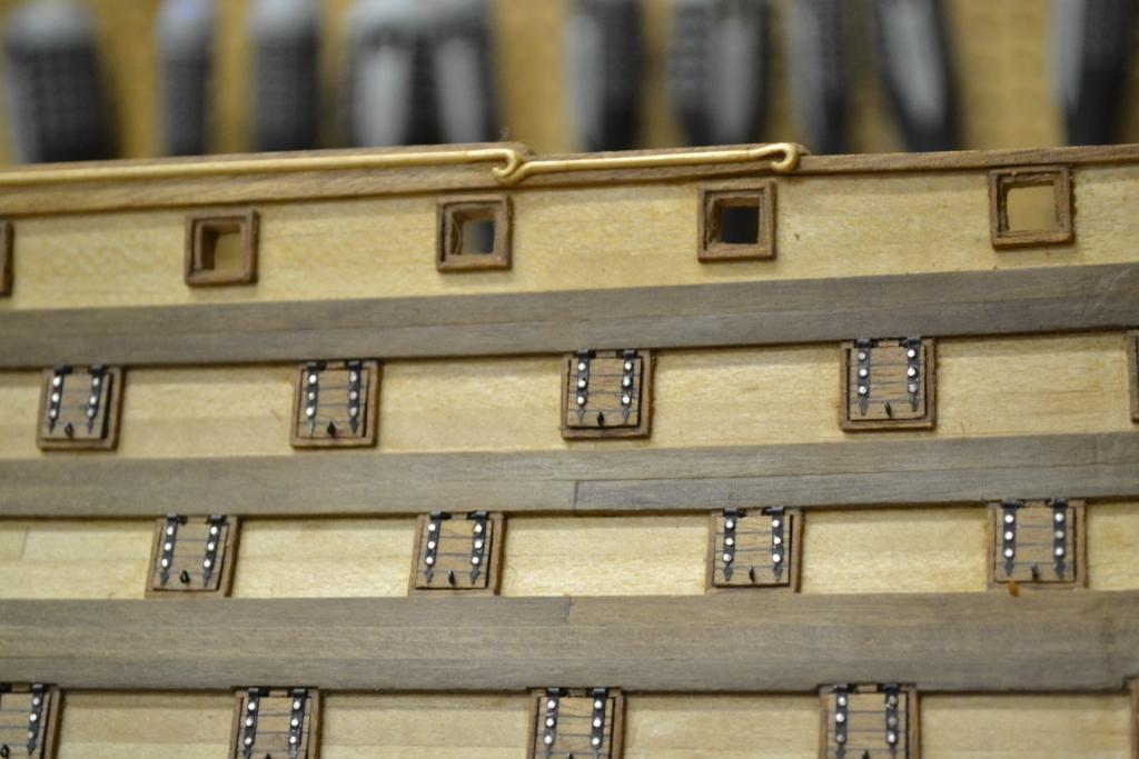
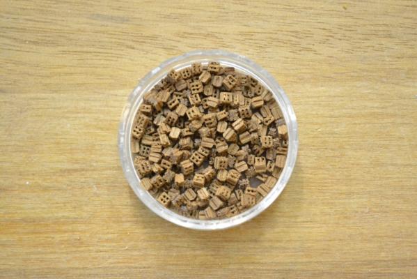
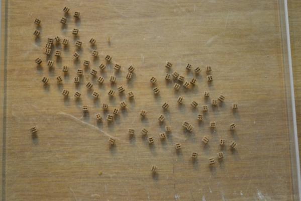
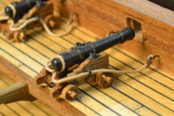
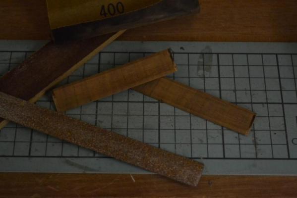
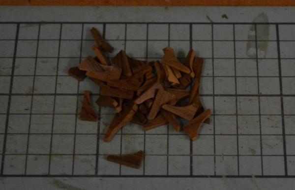
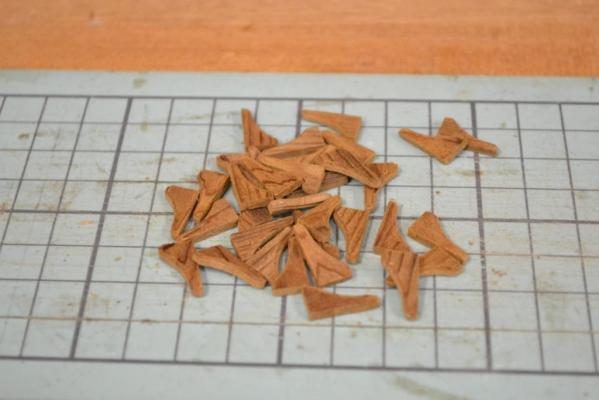
What can I say.. Time flies and work & other tasks prevents me from working on the project.. So this will be a minor update to show that I’m still alive & kicking I now have installed the breech rope on most of the cannons. At last the router bit arrived so I was able to continue with the canon rigging blocks. I used boxwood to start with, but decided to redo them as I find the boxwood color “to bright”, so after some experiments with walnut, cherry, pear I ended up with sapelli as the “best color” The downside is that Sapelli is grainy and it easily breaks for these (2mm) block-sizes. The unprocessed result.. After "tumbeling" with grain 150/400 in app. 10 minuttes The next thing was “how to rig a cannon” ? .. After some research on MSW, I ended up with the following… As usual the first one seems to takes ages, I’m sure it will get a lot better after installing number 20..
-
Hej Vince, I’m not sure in what order the euromodel instructions guide you at this stage but... i noticed you allready have placed the false keel at this stage of the build. In my instructions (OCCRE) I had to place the false keel first at a pretty late stage .. Personally I would start with “shaping” all the frames (and keel) and check the lines with a lath before even placing the false keel.. ..Check out here what I mean..
- 593 replies
-
- 1
-

-
- royal william
- euromodels
- (and 1 more)
-
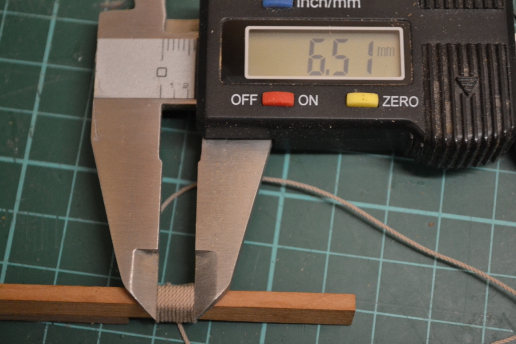
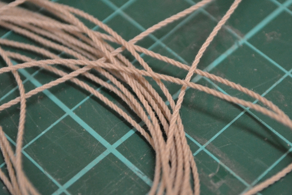
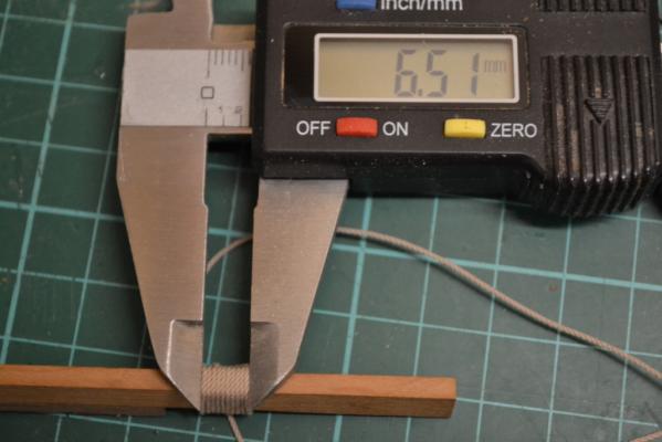
Hej Rob, She's looking great !!, just keep the pictures coming. By the way: Another way to find out of the (real) diameter of the rope is to wind it around a piece of wood in for eksample “10” turns Measure it with a caliper and divide the number by the used number of turns The diameter of the rope in the picture would be: Ø 0,65 mm
- 295 replies
-
- 1
-
-
- victory
- caldercraft
- (and 1 more)
-
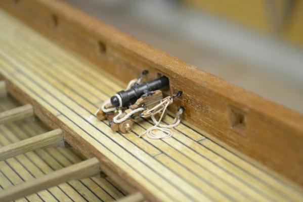
.. Still waiting for that router bit to arrive :mellow: .. So in the mean time I practiced a bit on the breech rope. To be honest what you see on the pictures took me quite some time to produce . Basically I had to reinvent the wheel, as I never did anything like rigging before.. But after having found out how I wanted it and which tools to use, it seems to get a lot faster. I also spend some time to find out what kind of rope and which color to use for the canon rigging. I settled with “sand” as the color “brown” seemed to fade away in the background The rope itself I made (on my home made ropewalk) with a total of 9 strings and it measures Ø 0,65mm. A bit more info about the rope for those who also make their own rope: I made 3 “Hawser Laid” or “Twisted” ropes from 3 yarns and used 3 of these ropes to produce a “cable laid” rope. Intentionally I also wanted to rig for the “train tackle” but as you can there’s not really any room for such rigging as the main hatch is right behind it when the guns are in “loading” position.. So i guess i have to give up that idea..


-
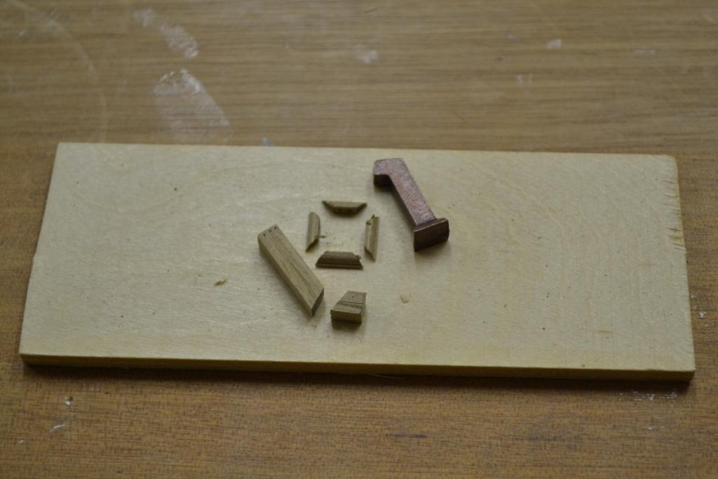
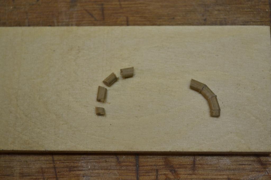
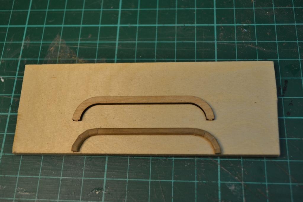
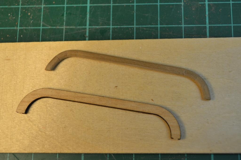
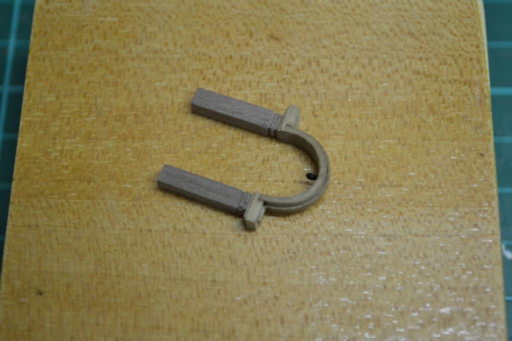
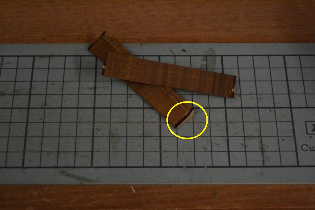
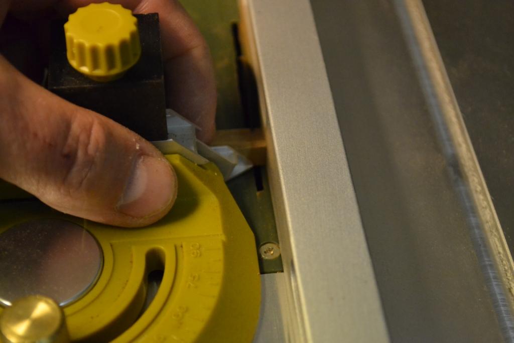
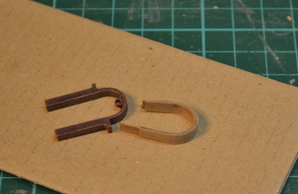
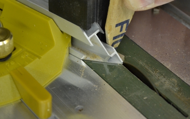
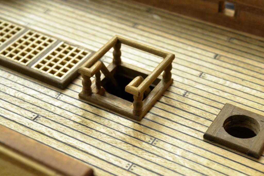
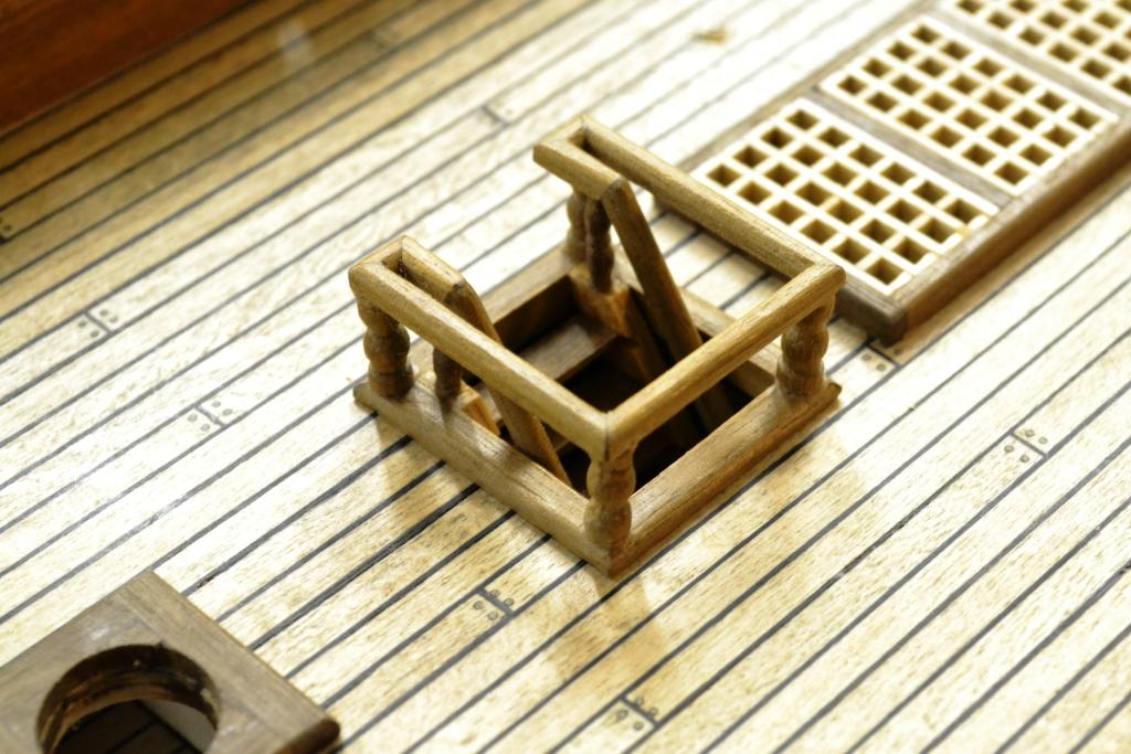
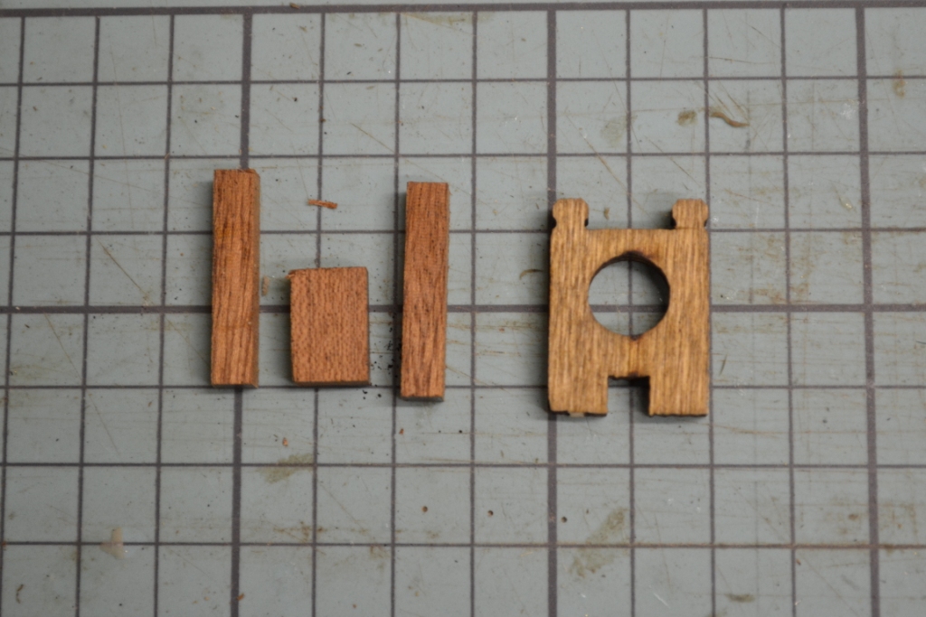
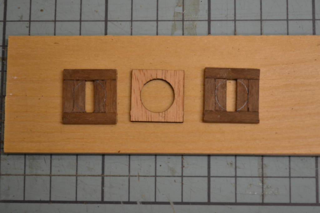
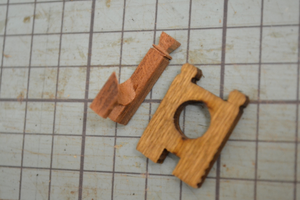
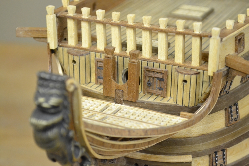
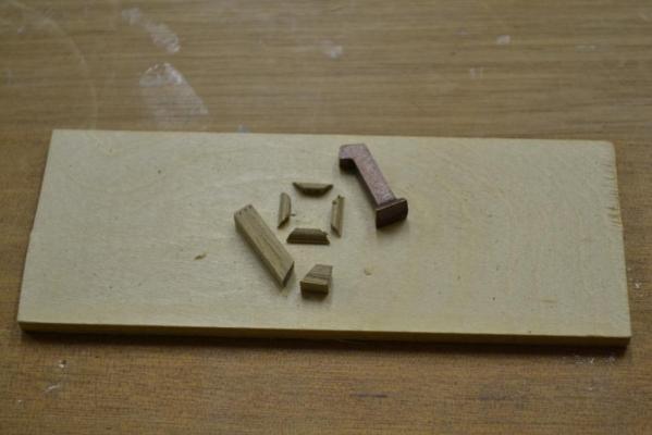
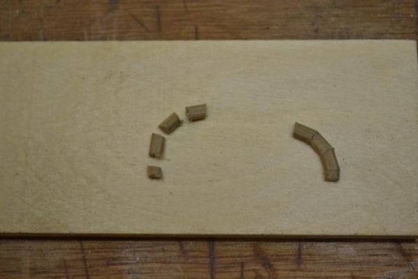
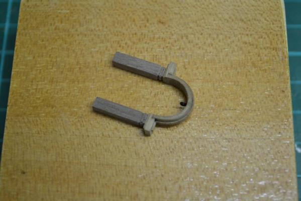
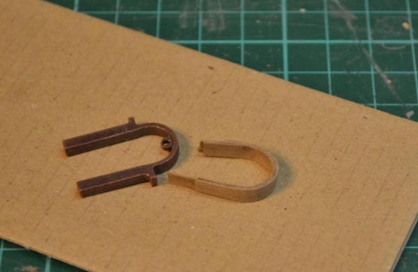
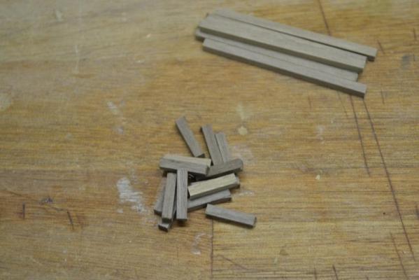
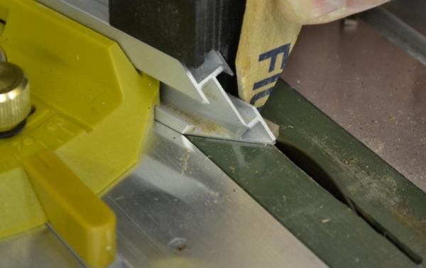
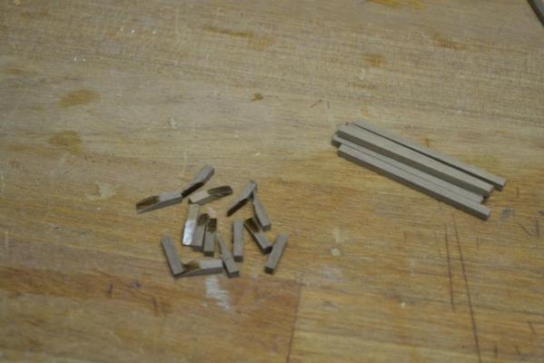
I tried to install the cannons under the quarterdeck today but I had a bit of a setback.. During manufacturing of the cannon rigging blocks, one of my very small router-bits snapped and I have to wait now for a new one to arrive :mellow: .. So to kill some time and to be a bit constructive I continued with manufacturing some of the remaining fittings. I started with the chimney, again the supplied one was made of cast metal, and I made one in walnut .. I also had to manufactor an curved handrail, which I had saved for last. I tried some time ago to bend the handrail by soaking it in water for quite some time, but the curve was just to narrow and/or is walnut wood just not flexible enough. So again the table saw helped me out by cutting 4 very small (app. 11 degree angled) pieces of handrail which I glued together with carpenter glue. After this it was just an matter of rounding the whole thing with sandpaper & scalpel Here they are installed..


-
Same here, I just can’t see the repair .. Either we need a macro picture or you have to highlight the lines/fix Very well done !!
-
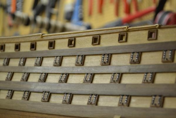
Hej Sailer1234567890, You are absolutely right, after blackening & fitting the sheaves I was a bit disappointed as well. .. as you correctly noticed, all the details (& efforts) disappeared.. To comfort me I said to myself that the details would have been disappeared anyway when all the ropes are fixed in place...
-
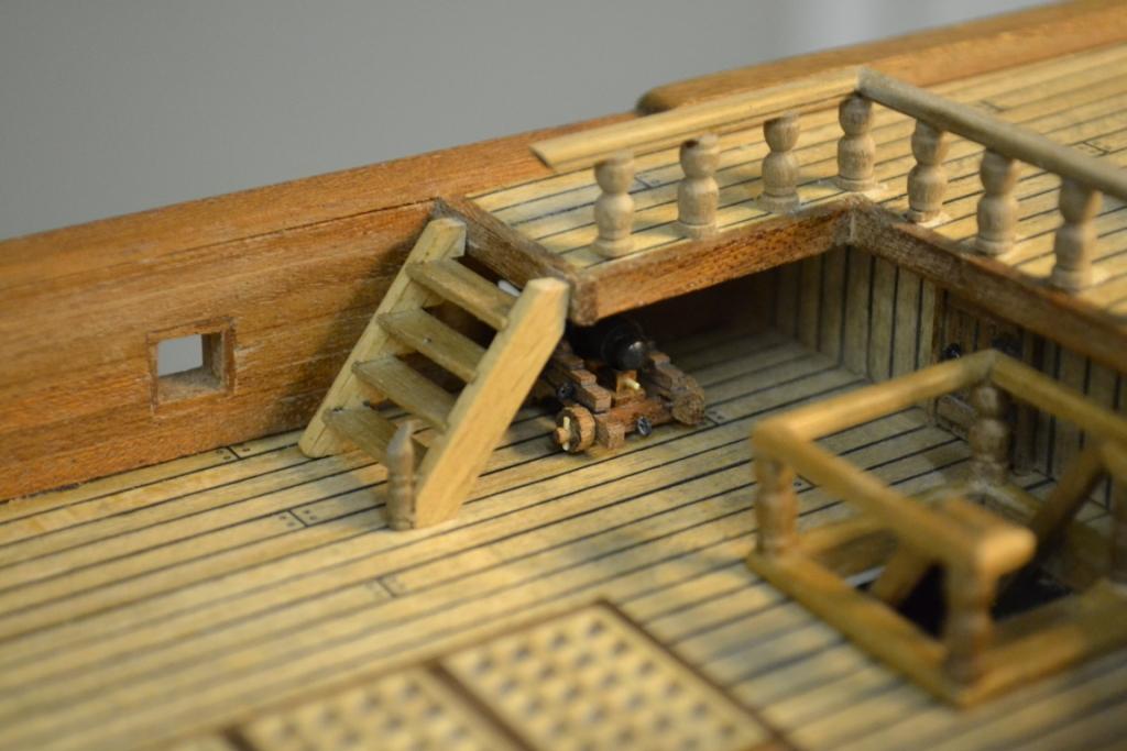
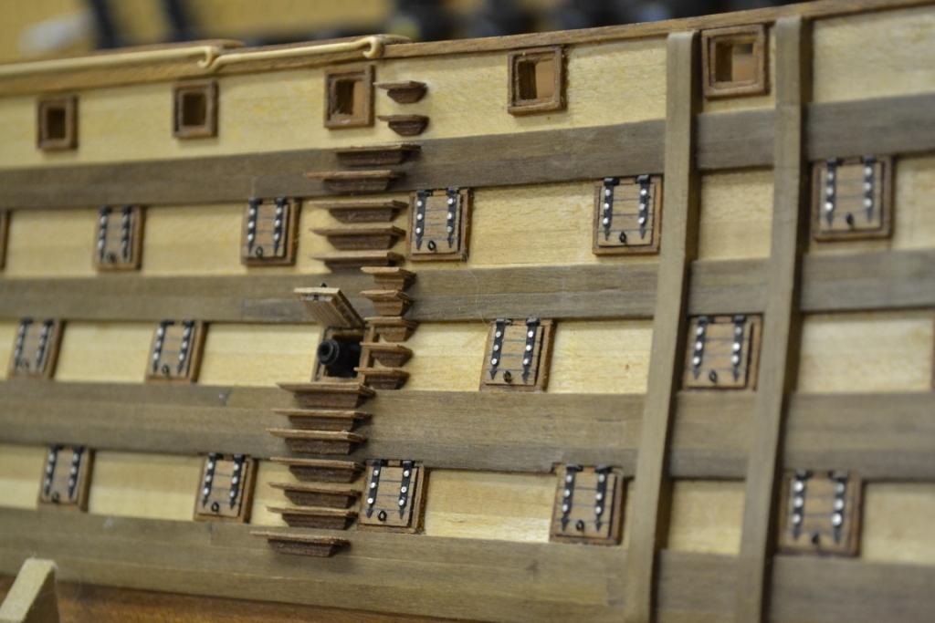
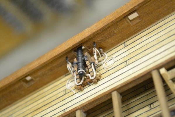
To all you Santisma Trinidad builders out there. .. .. Be aware of the following!!.... Just before gluing the quarterdeck ladders in place I realized suddenly that the planned cannon rigging and drilling holes behind it will be quite a challenge.. So ‘m forced to do some cannon rigging before continuing with the deck furniture.. But even without the ladder in place I’m afraid this will be very difficult For me (being allready at this stage) it’s not so nice to remove the quarterdeck anymore, so let’s see how things will go from here..

-
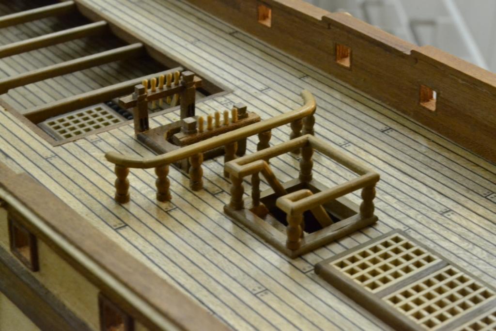
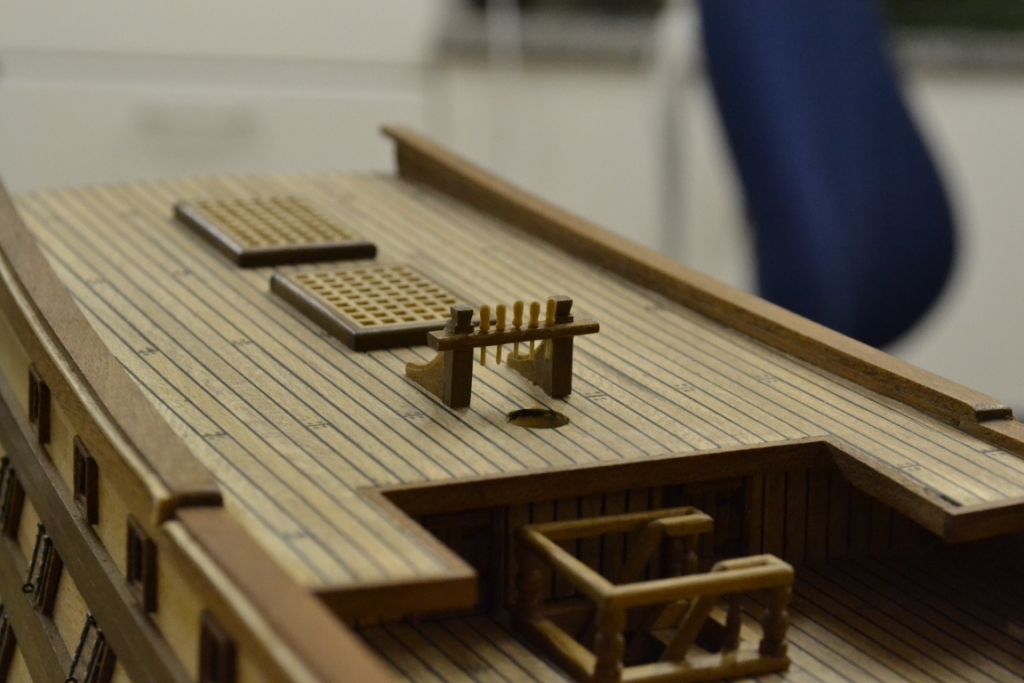
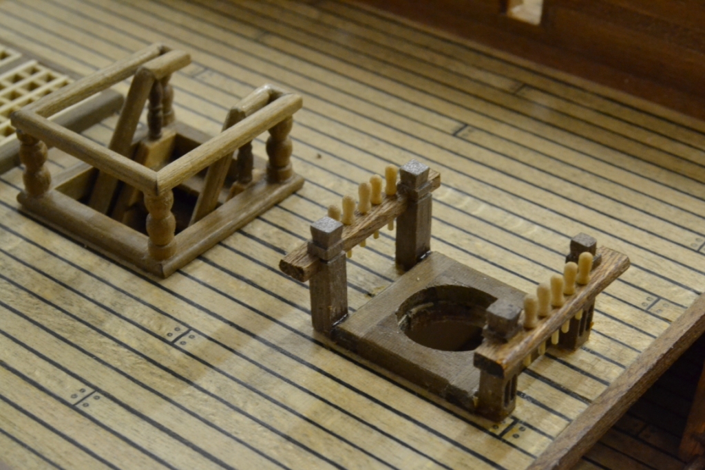
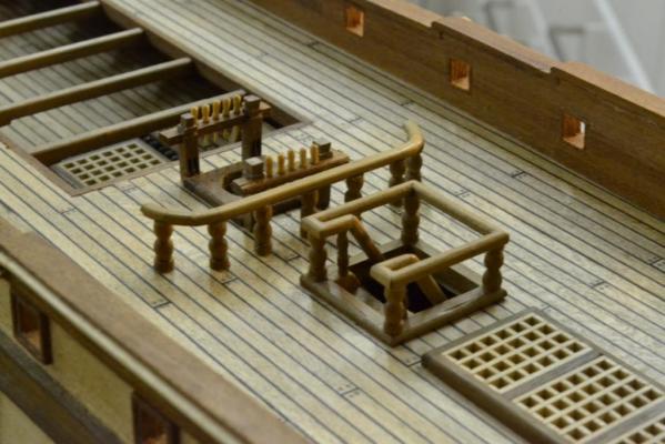
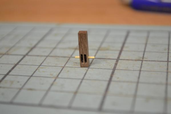
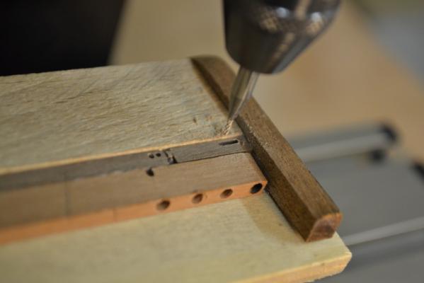
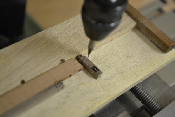
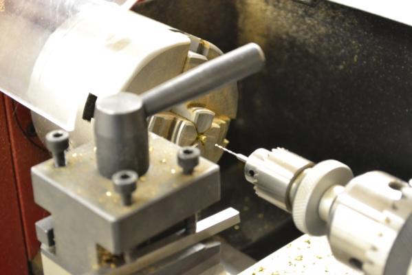
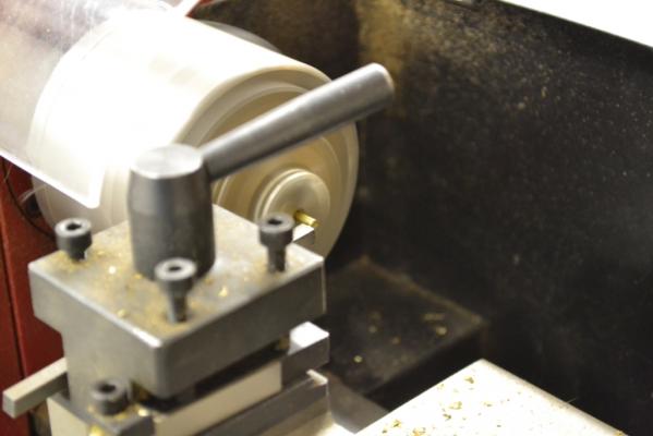
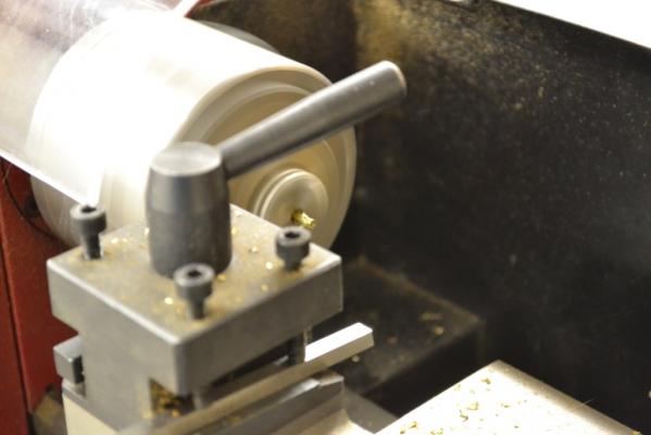
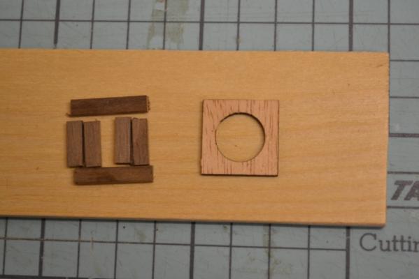
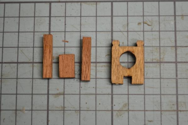
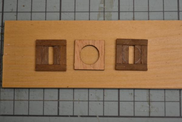
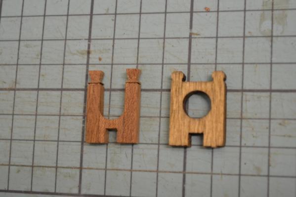
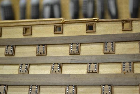
I worked mainly on the belaying pin - rack assemblies (fife rails) this weekend, and discovered that the supplied belaying pins where totally out of proportions So I spend quite some time in trying to manufacture my own (I created an separate post about how I made them) .. link to the post .. Besides the belaying pins I placed 2 sheaves in 4 knightheads (I believe these where used for the lower yard tackles of the fore and main mast) i Started with milling of the sheave openings in the knighthead I manufactured the sheaves with a lathe from a 2,5 mm brass rod using an home-made cutting tool, drilled an hole in the middle and used an cutting tool to separate the sheave from the rod Blackened the sheaves and fixed them in position by using a Ø 0,7mm bamboo stick Added also some details to the knightheads the cross piece is as suggested by the kit but I did round the edges on the front. Here are all of them glued into position including the scratch build belaying pins..


-
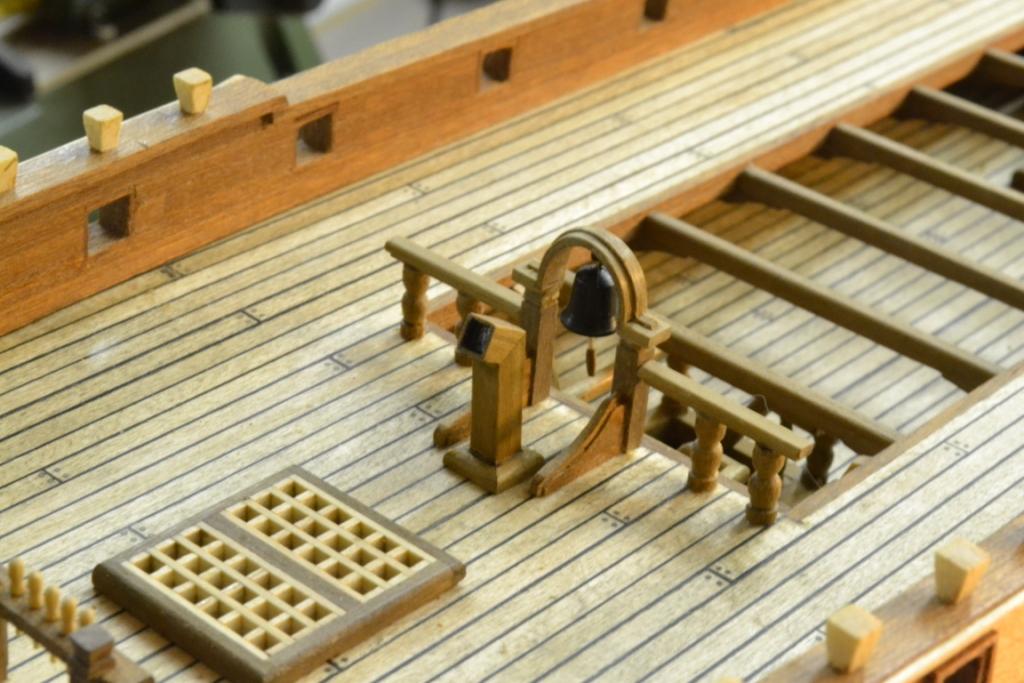
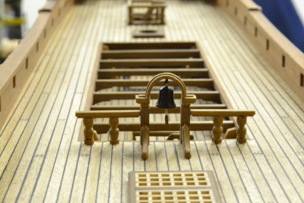
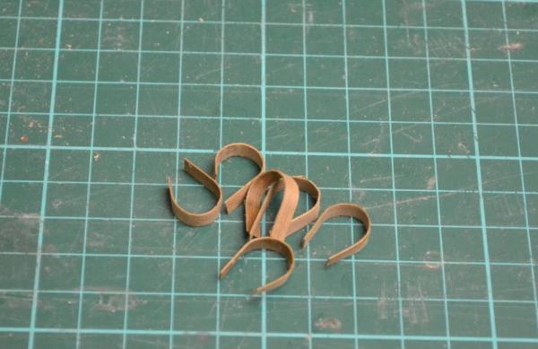
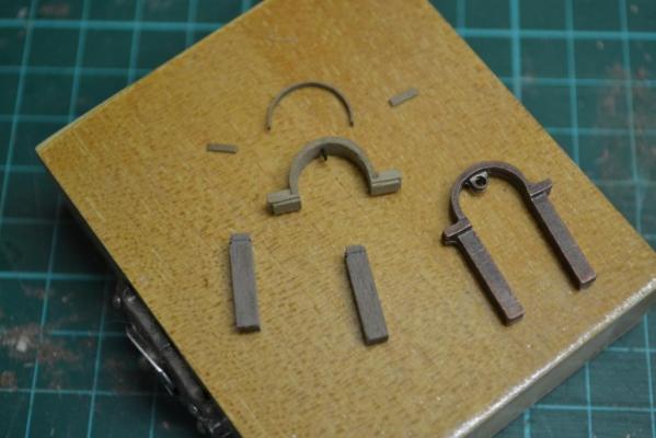
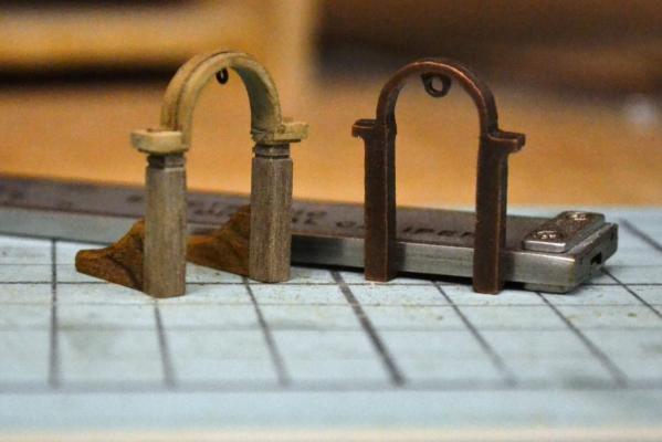
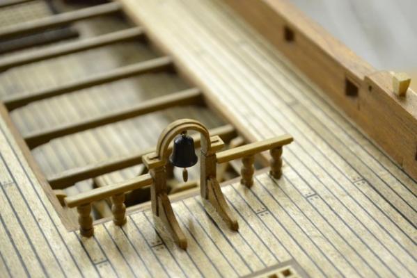
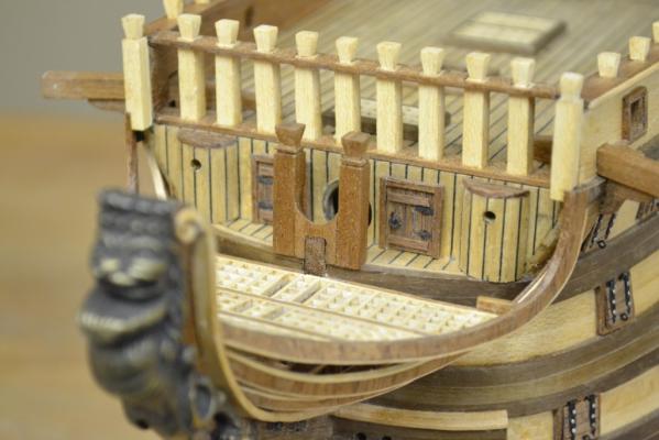
Thank you all for the likes & the comments, they are (as always) appreciated a lot and very motivating, keep them coming I hope I don’t bore too much with all these “how I create stuff” pictures as these might not be relevant for all of you followers... ..Right now I feel I’m starting to run in circles.. Off course the supplied “metal cast” bell-tower didn’t matched the rest of the wooden interior, so my next project became the bell tower. The biggest hurtle was to find out how to create the arc from wood. I made it by cutting very thin strips of African walnut, soaked them in water and wrapped & dried them on a 10mm drill-bit afterwards. After gluing 3 of them on top of each other ..the result.. I used the kit’s bell tower as the reference and together with my imagination I added a bit more details to it. “2” laser cut “plywood” !! :mellow: Brackets are needed when installing the bell tower (“32” brackets will be needed for the entire build) So I setup an small production line and made enough brackets from a piece of 10mm redwood which was available to me. I glued the brackets supplied by the kit at the end(s) of them and used these as "shaping guides", I shaped them, and cut individual “brackets slices” afterwards on the table saw . To add a bit more detail I wanted to mille an edge in the curved top of the brackets. To achieve this a came up with the idea to mile the bit (with the appropriate depth and width) into a round piece of scrap wood. Luckily the brackets where not too small and by using toothpicks and a pair of tweezers I could avoid milling my fingers Off course "afterwards" (when looking at the macro pictures) I can now see a lot of different “colors” Fortunately when looking at it from an distance it doesn’t show too much, but learned a lesson here: “next time use only wood from the same batch” So finally a few pictures of the bell tower fitted on the ship (including the (blackened) bell and accessories) and with the previously modified pillars & handrails ..Enjoy..


-
I finished all 3 staircases today, and I continued with manufacturing the beams for the main hatch. I'm extremely happy with my table saw and i use it whenever i can. All material and angles in the supports are cut with a table saw. But.. no fancy machines for creating the arch in the supports.. ..I became a big fan of jigs during this build.. Just by gluing 3 simple pieces of scrapwood in place and it will make sure that all the supports are glued exactly on the same spot. I rounded the top edges of the beams And glued them in place No secrets & as suggested by the instructions !!!

-
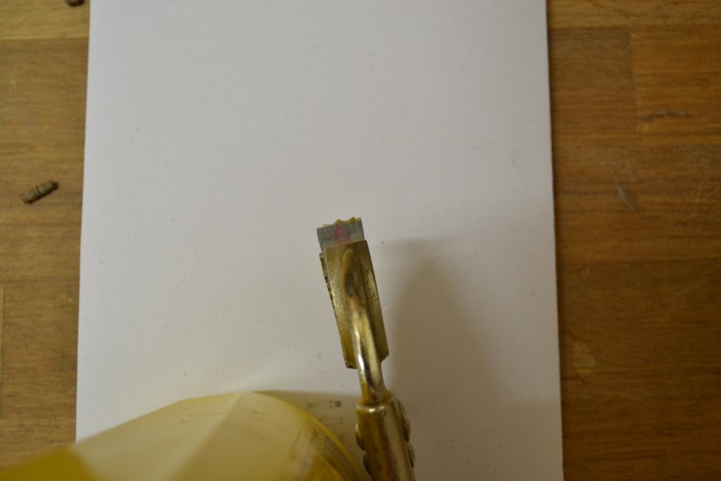
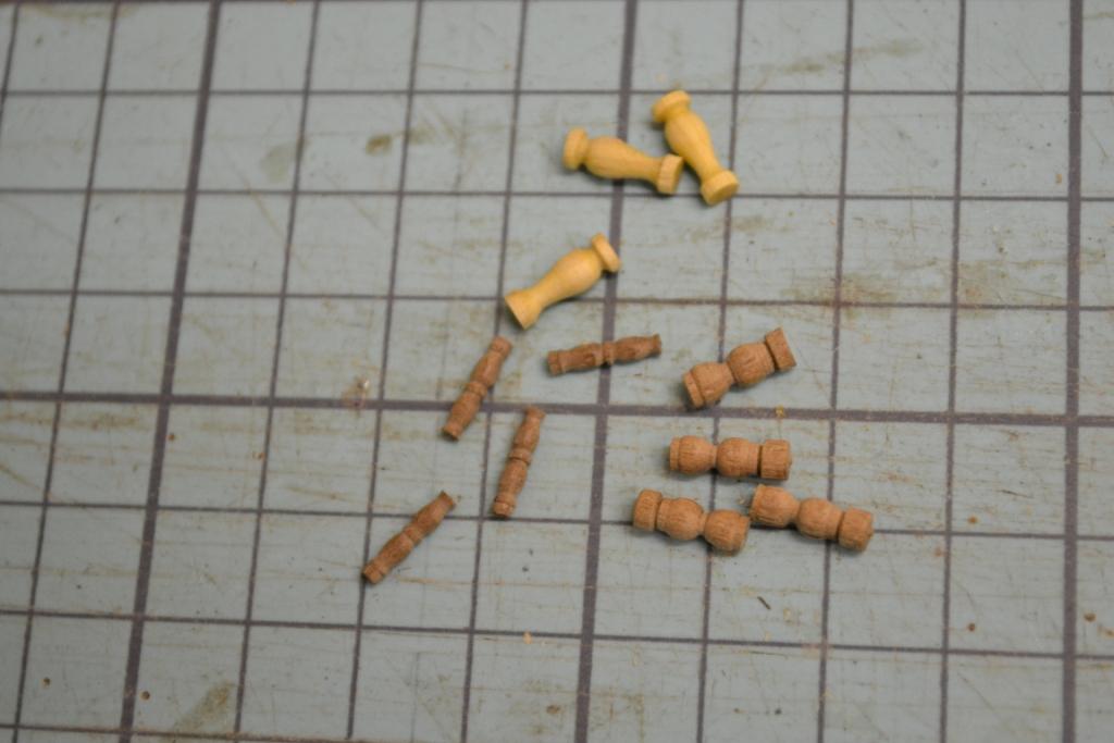
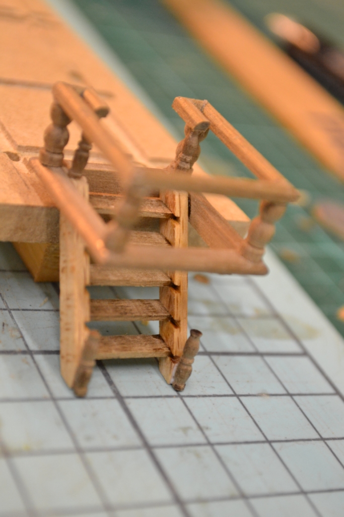
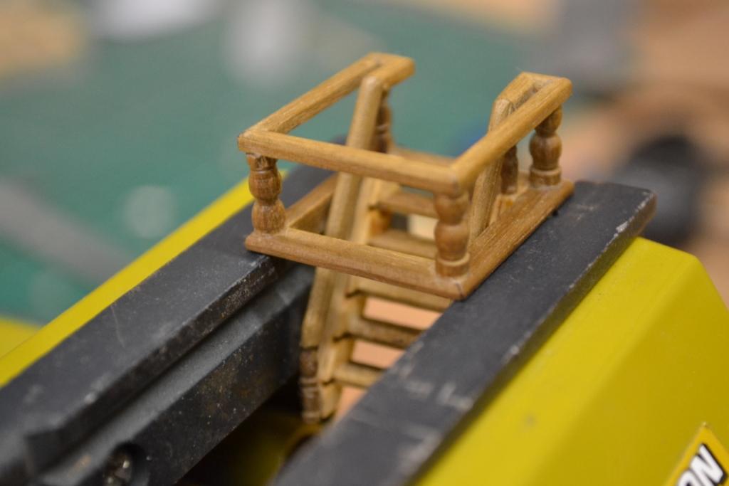
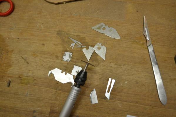
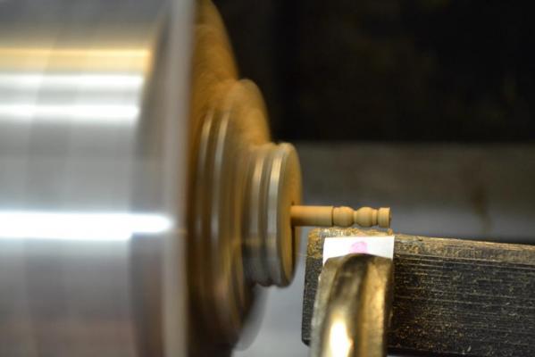
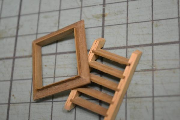
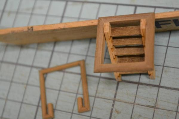
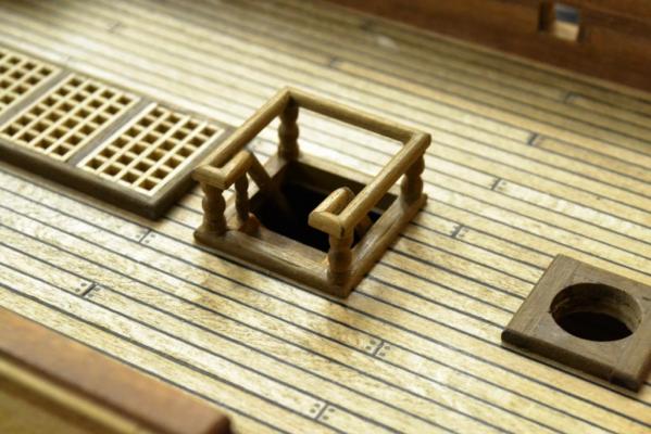
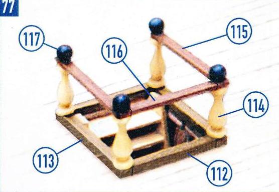
Thank you guys !!, I know the next part it is not exactly after the instructions either .. I don’t like all the “visual” plywood parts and as I’m not intent to paint my model I try not to use too many different materials/colors. According to the instructions the stairs to the lower decks should be made as shown down below. I find the supplied columns slightly out of scale so I wanted to change them. Browsing through MSW I stumbled over scrapers and I decided to make one from used scalpel blades and by grinding a column pattern into them .. I used a thin grinder but still it was not easy, not very accurate & it removed very quickly too much. .. just by trying, trying & trying.. finally !! (more luck than science) I had created some usable scrapers By using a round stick in a lathe (unfortunately not my own) and using the scraper, I succeeded to produce some columns in a better scale After this I also wanted to change the handrails a bit. I needed 3 Staircases, so I decided to use a jig to make sure to keep all the parts in place and in the right angles during the gluing process. I noticed that some plywood around the hatches would still be visible after mounting the stairs. I glued a very thin border around the frame to prevent this and mounted all the columns and the handrail section. And added handrails to the stairs. Here it is, the very first one waxed & fitted in position.. ...


-
Continuing with the deck "furnishings".. And continuing the current trend by scratch building the mast partners by using some remains of the supplied walnut strips by the kit. As well as the the plywood supplied bowsprit knighthead … ...


-
Hej Klimi, Just stumbled over your build log .. Really a great build with quite some inspiring input !! I certainly will follow, keep the pictures coming
-
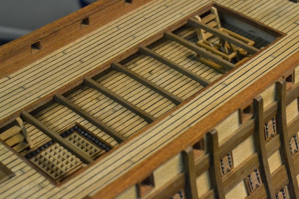
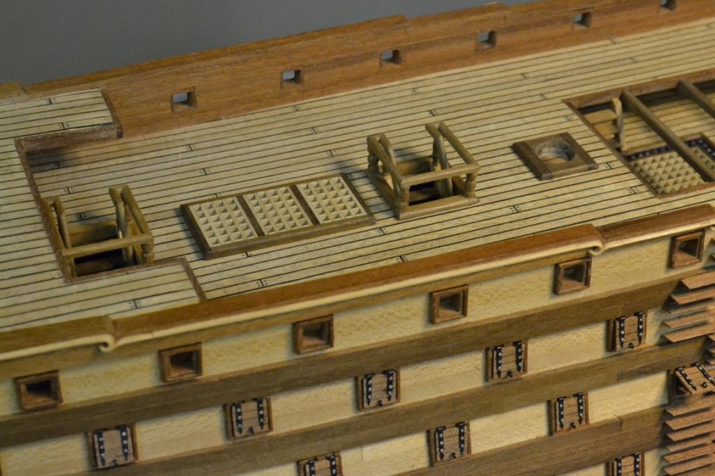
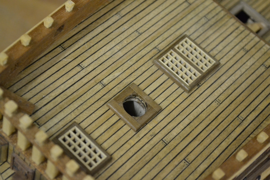
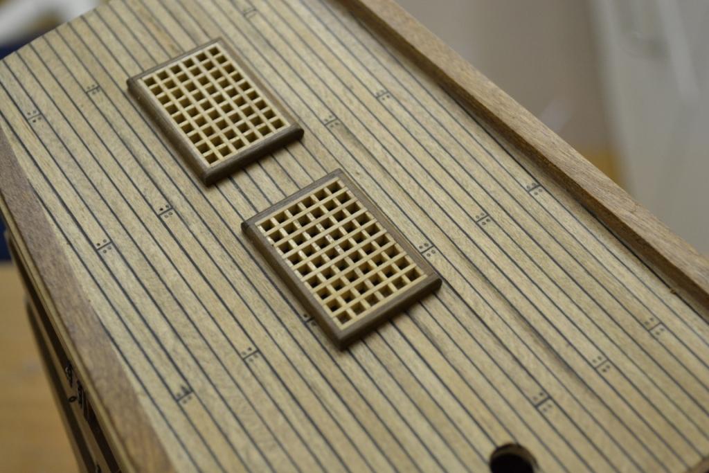
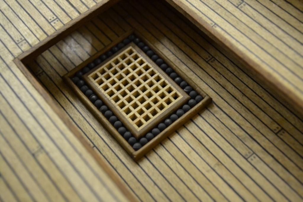
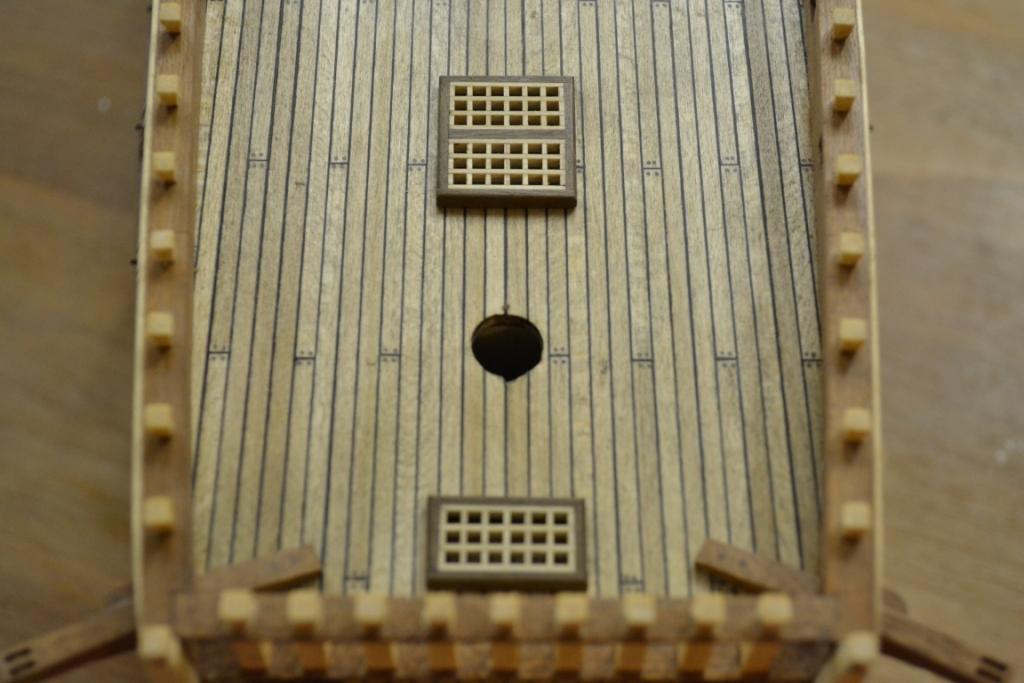
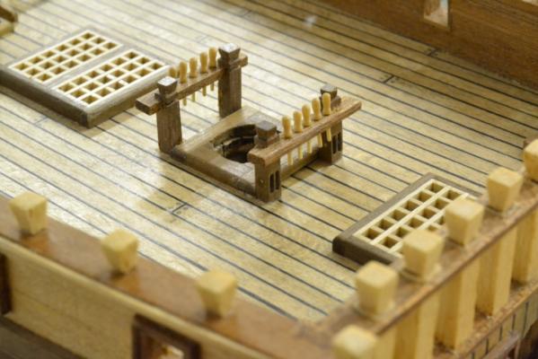
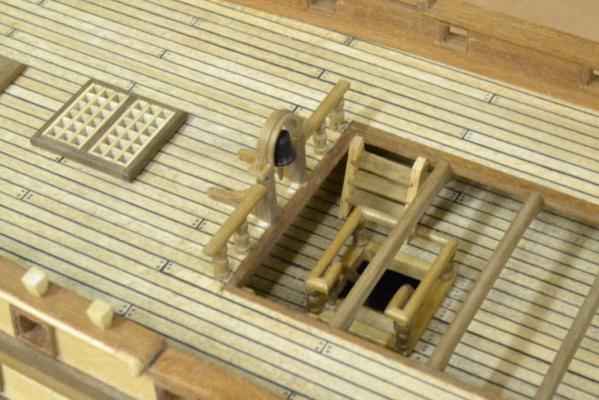
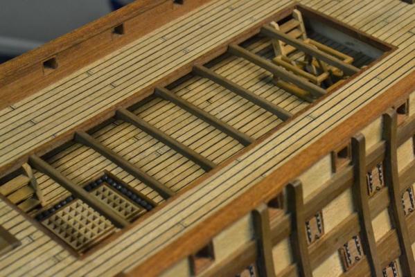
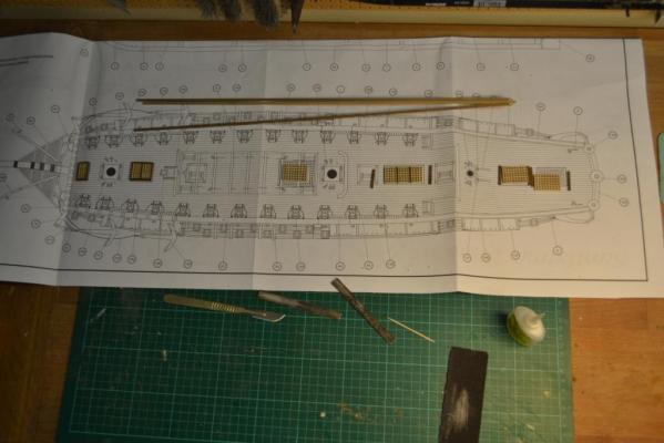
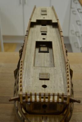
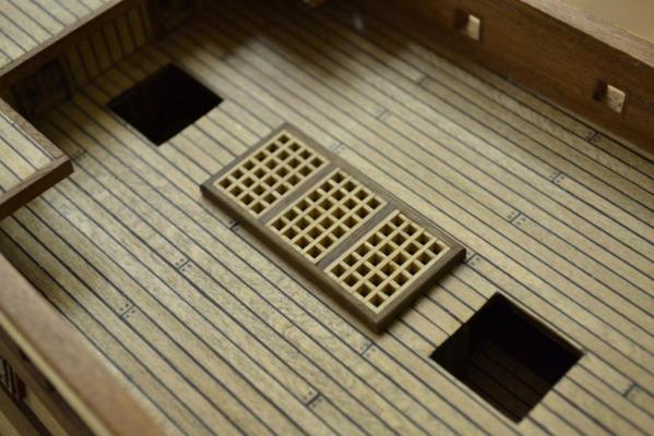
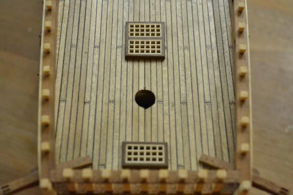
..An small update with an nice impact.. Today I assembled the gratings and glued them in place. Straight forward, and pretty much as suggested by the kit .. I did rounded all edges before installing them .. It seems to me that there are not enough cannon balls supplied by the kit. I’m not really happy with them, so I might find some others before gluing them finally in place.


-
Hej Sjors, Wow. She is HUGE !! Are you sure you started building the 1th of January ? You're are working fast ! .. a Great job so far ..
-
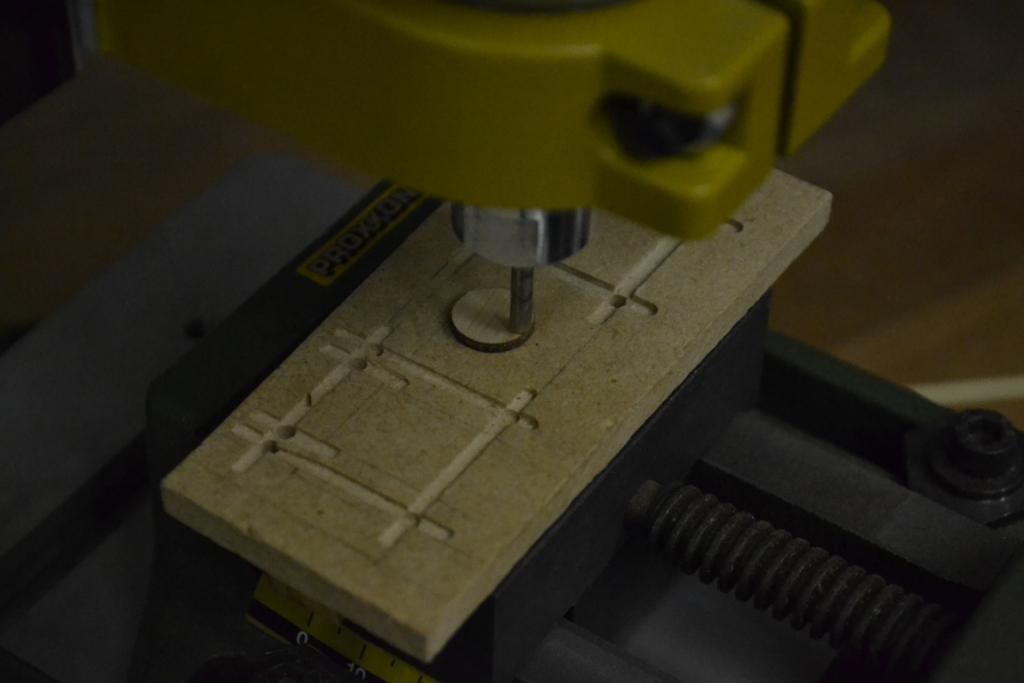
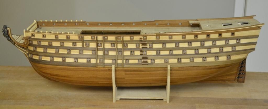
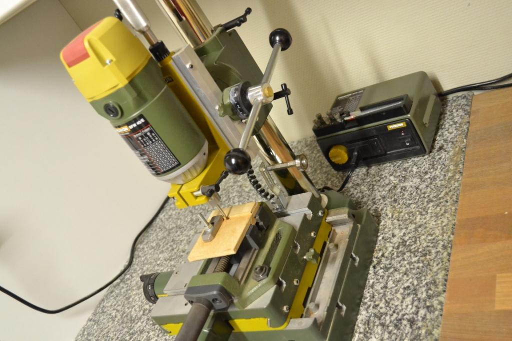
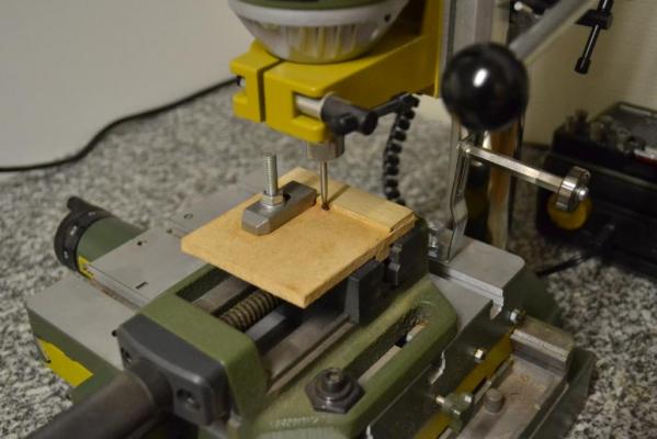
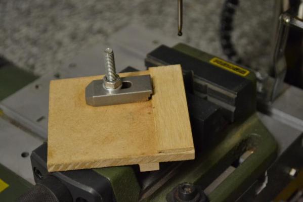
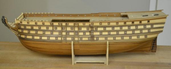
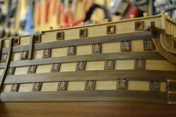
Ok,ok .. after all these macroshots and close-ups a few wider shots Bug, The guide I made is pretty simple, I made it because I can clamp it easily in my vice(s) and it can't damage any milling bits or drill bits I used 6mm MDF wood and a wooden paint-stirrer as base material. To keep subjects secured in place (and avoid milling my fingers) I mounted part of the clamp set (P/N: 24 257 Proxxon) on it The mill setup I use is from proxxon (more or less because it is the only manufacturer for small hobby machines in Europe) I highlighted some advantages & disadvantages in another topic earlier which can be found here : Link Sailor, here she is at the current status .. (in an extreme wide shot) unfortunately the file limitations on MSW prevents higher resolutions, so many details are fading rapidly..

-
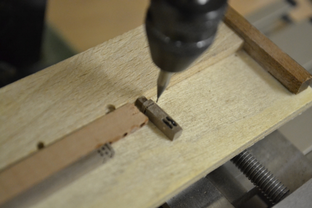
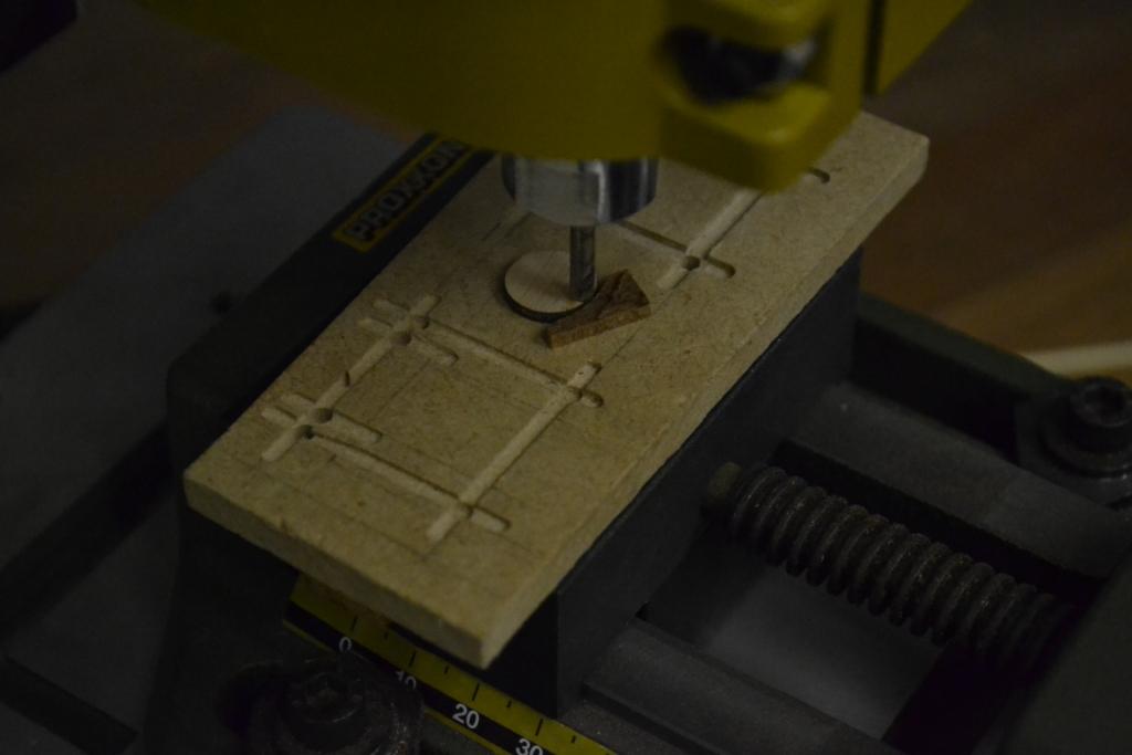
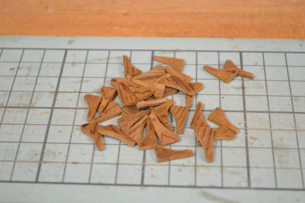
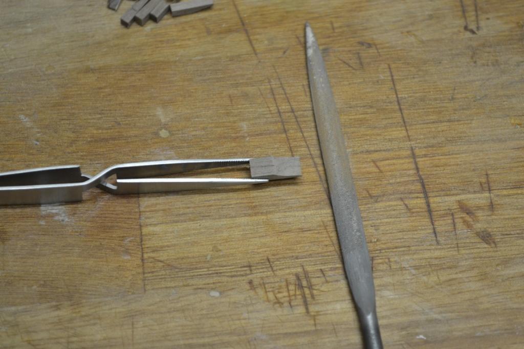
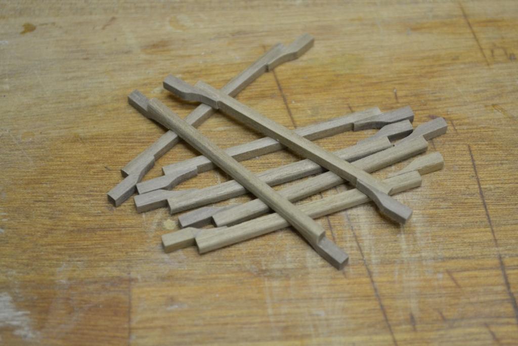
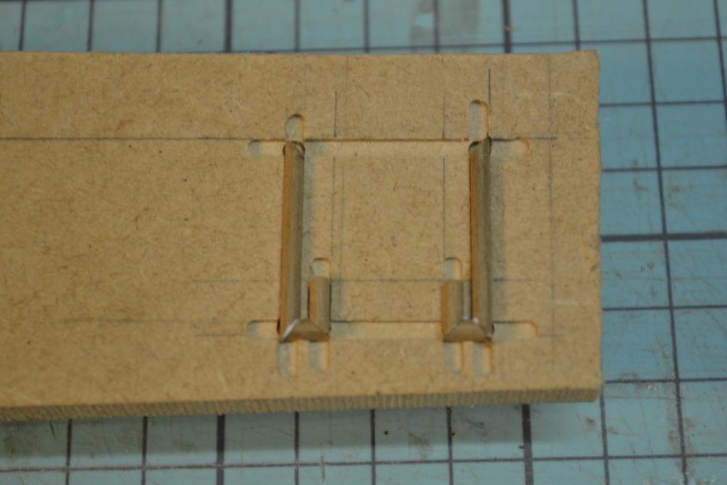
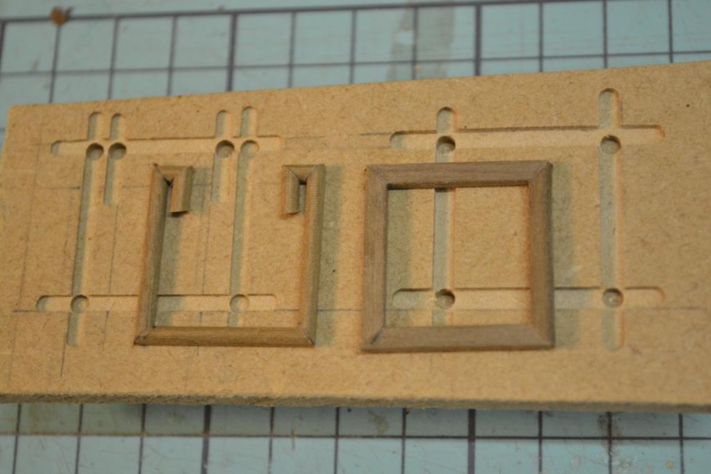
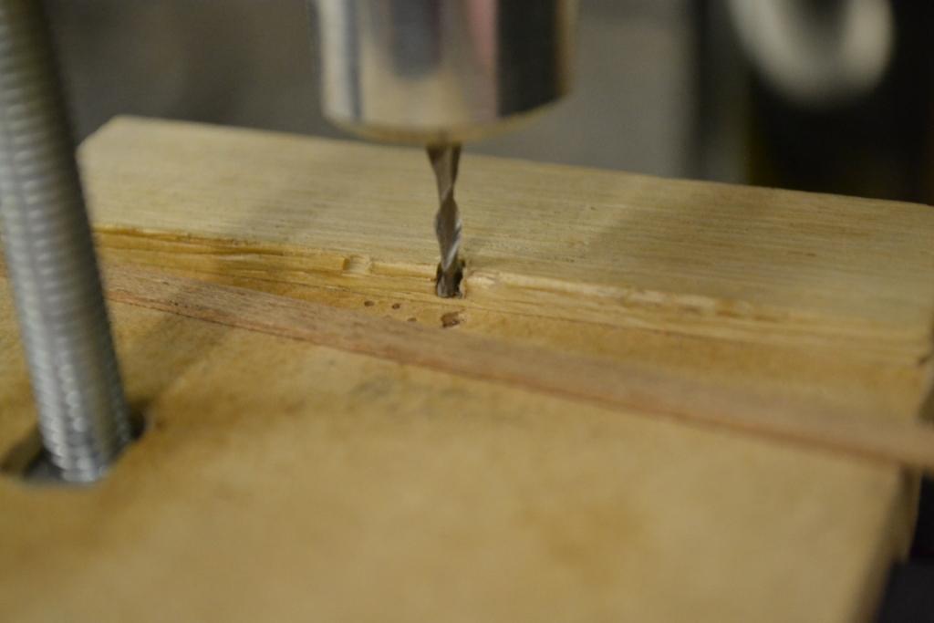
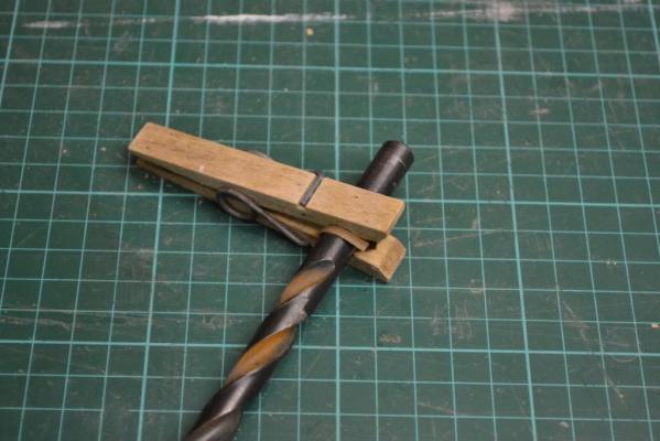
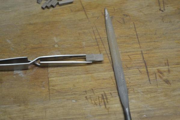
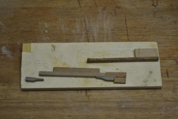
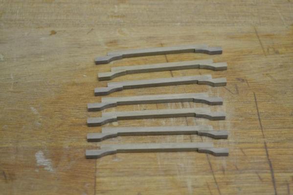
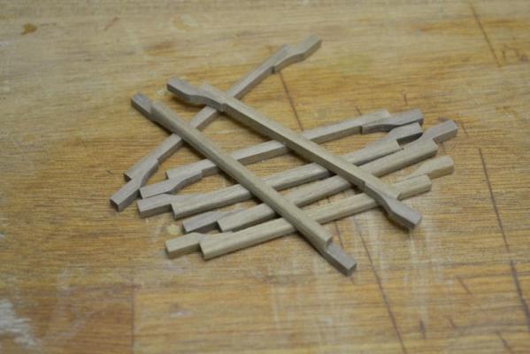
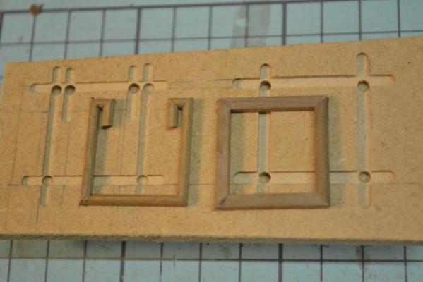
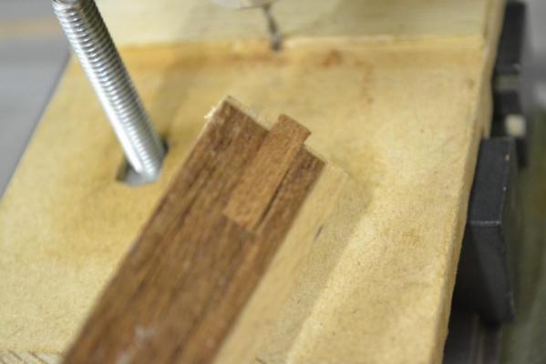
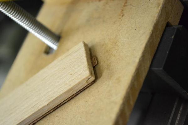
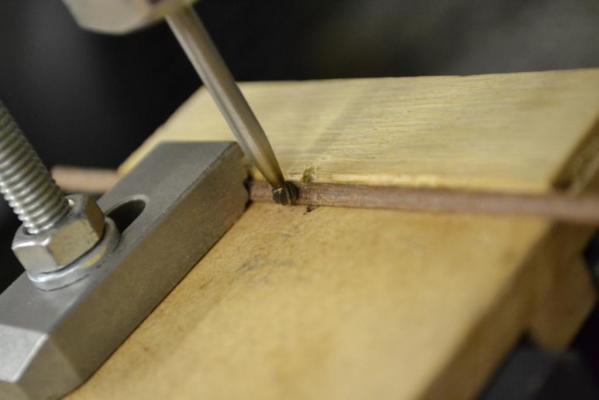
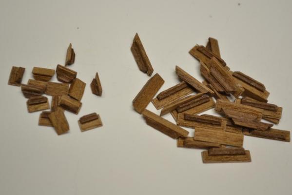
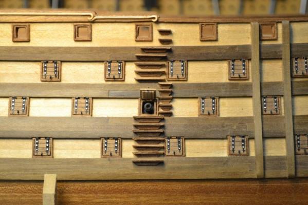
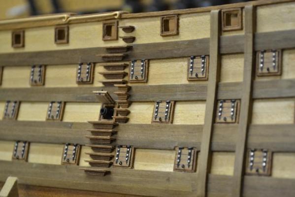
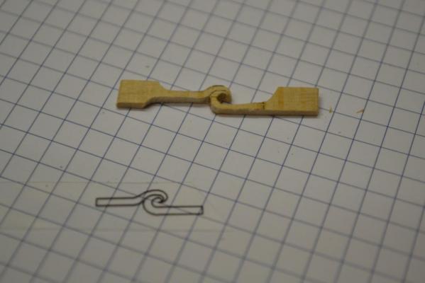
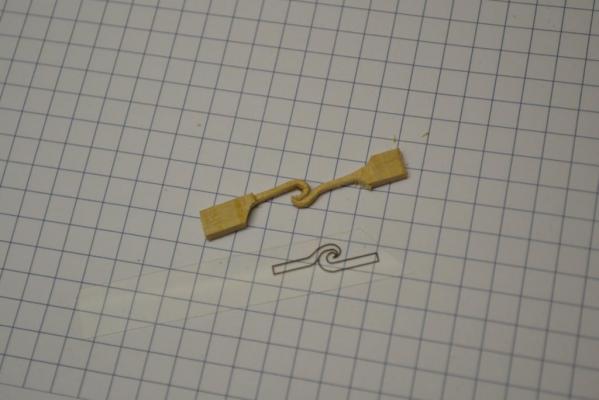
Thank you all for dropping in and the fine comments !! To Moonbug: I found out that you have to be very very “gentle” when using sandpaper this way ..I’m surprised myself about the carving result and this got my mind set to the stern. I’m now convinced that I also should be able to “scratch build” the stern decorations. But first the ladders, and, ..“off course” .. I just couldn't resist and had to add a bit more detail. I wanted an “edge” around the rungs to add more detail and to create a slimmer look. To achieve this I milled a 2 mm routerbit (with the appropriate depth and height) into my primitively made guide and milled the edge in the list. After cutting the rungs they became too small to hold them by hand, so I made a “tool” to hold them and milled the remaining edges. I milled an groove with a round routerbit to get a nicer base shape for the rungs Assembled all the individual pieces. ..And placed them ..

-
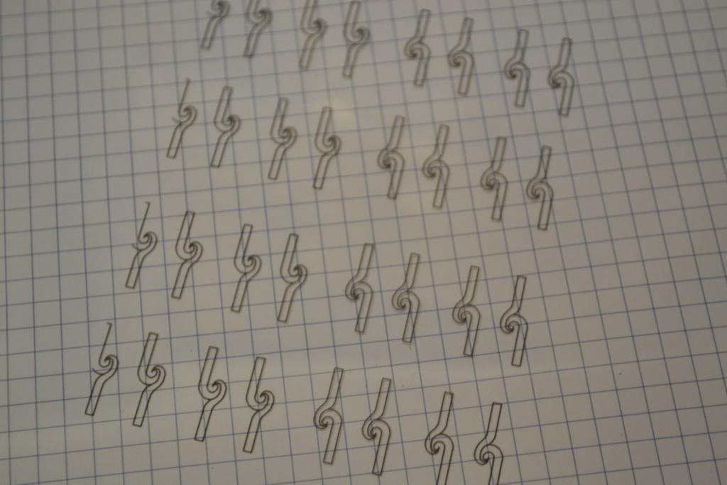
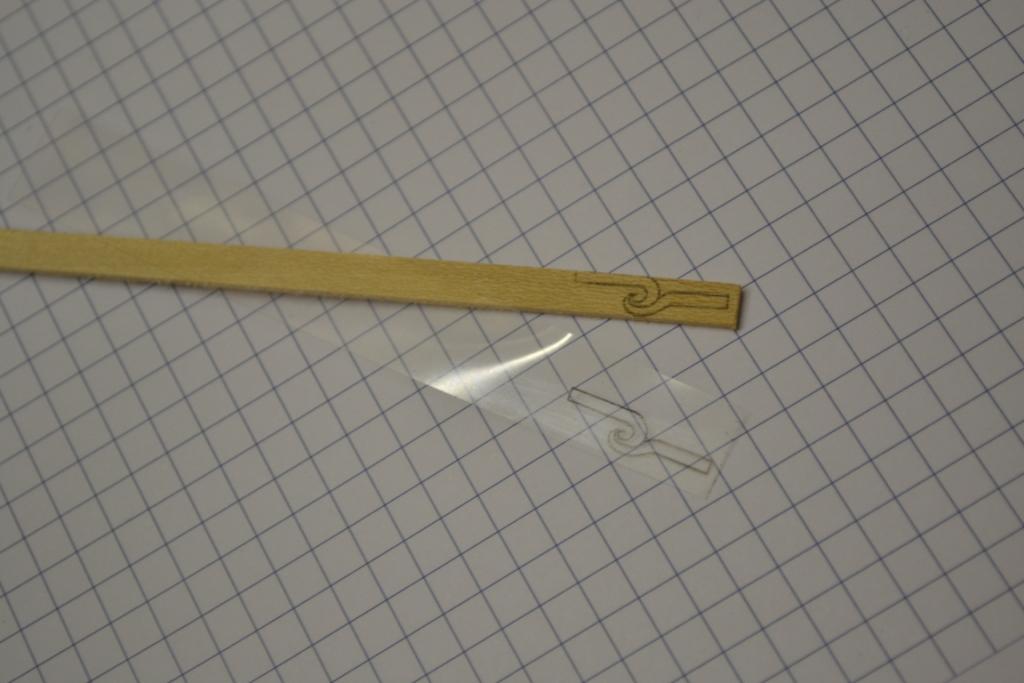
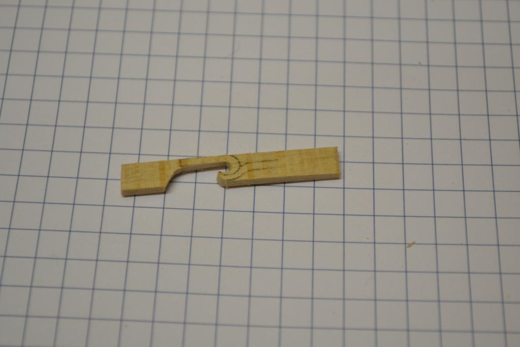
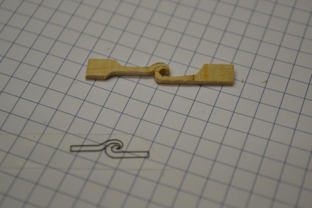
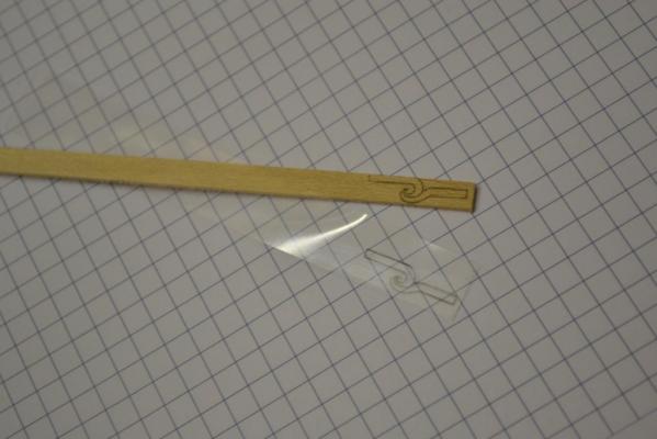
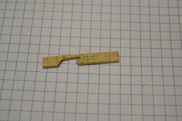
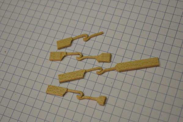
..Did some brainstorming about how to manufacture these "artifacts".. Sorry for the following (long) text but my findings in this case are not so easy to explain in a few words The First problem I had to solve was “consistency” From my earlier carvings (2 curls for the stem) I found out that it was not so easy to produce equal results. So I knew that drawing the motive by hand was not really an option. Cracking problem 1: I decided to use a so-called “CAD program” and “designed” the curl I needed ("not to complex" as I know my carving skills ) So after printing the result (on a laser printer) I had to transfer the motive “somehow” to wood. I tried soaking the paper in all kind of chemicals and hoped that it “magically” would/could transfer the motive to wood. .. without luck.. ..Maybe the results are different/better when using an inkjet printer.. An laser printer uses “heat” and burns “powder” very secure to the paper. So again “after a bit of brainstorming” I used an iron and hoped that by reheating the paper it would “transfer” the motive. .. without luck.. To keep the scenario short and share my findings: I ended up in printing the curls on a “transparent” foil (used for overhead projectors) and when reheating the foil (using an iron) it will actually “release” the powder particles to wood !! "Cracked" problem 1 ..i believe.. So...Next challenge was the carving itself I think it is easier to show the progress with a few pictures Using a fretsaw ? to cut-out roughly the contours And the result after using a sharp scalpel (blade 10) “Polishing” the result with a thin strip of sandpaper (1500) “More or less” 4 equal results.. And installed/waxed them on starboard today. .. enjoy..


-
Thank you all for the positive input, likes, advice and the quick responds !! ..Special thanks to Nigel for the link to the “original?” plans of the ST.. As it seems the entry port is now on hold as there’s no such one in the drawings But something else has now my attention !! So this might be the next challenge I will work on, "my carving talent" ..

-
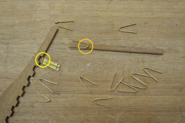
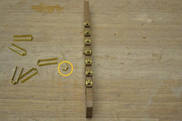
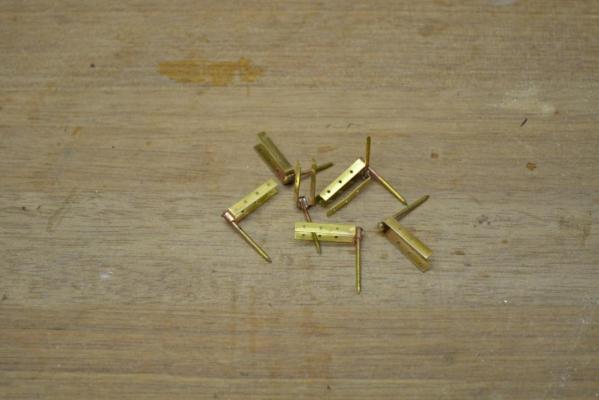
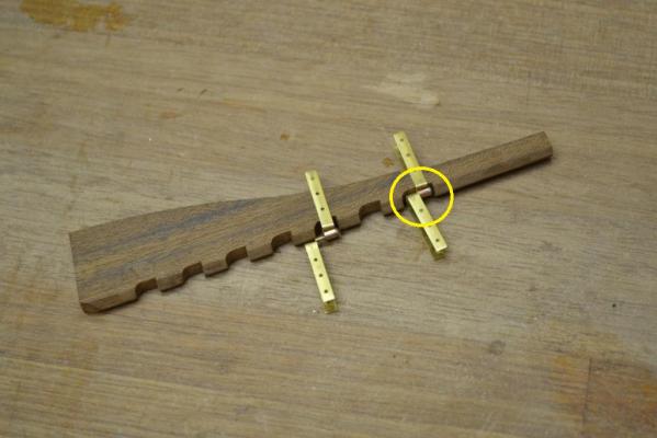
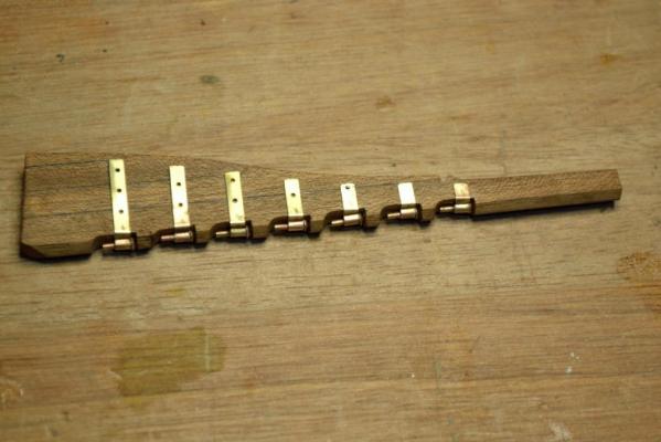
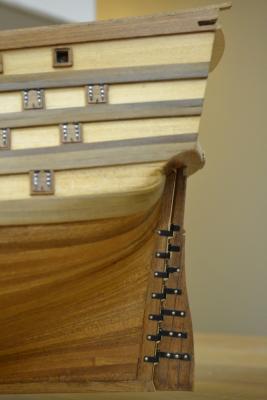
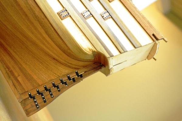
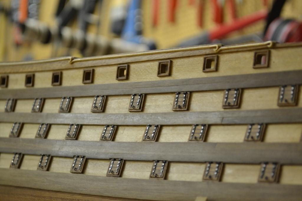
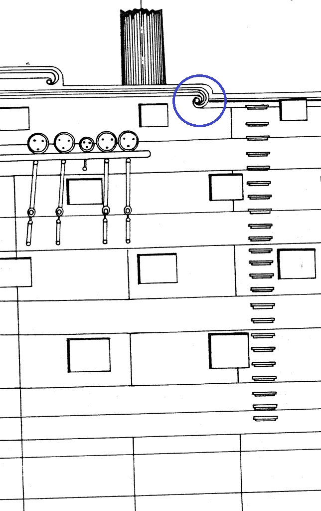
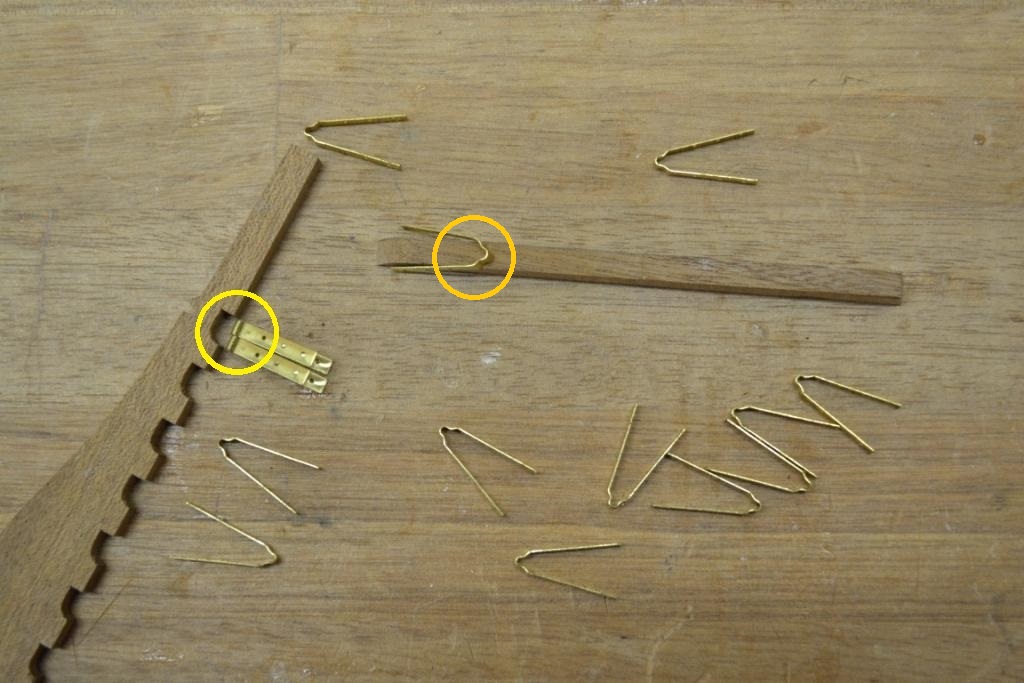
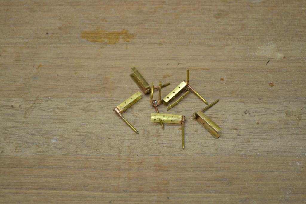
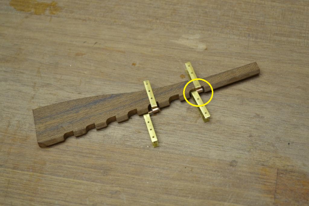
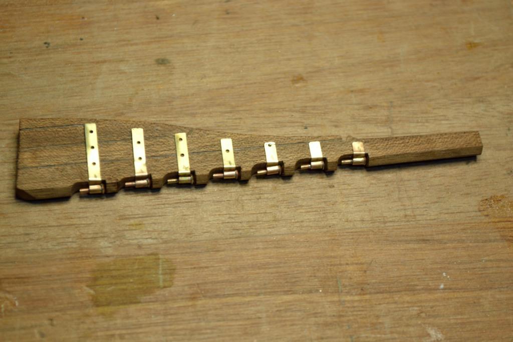
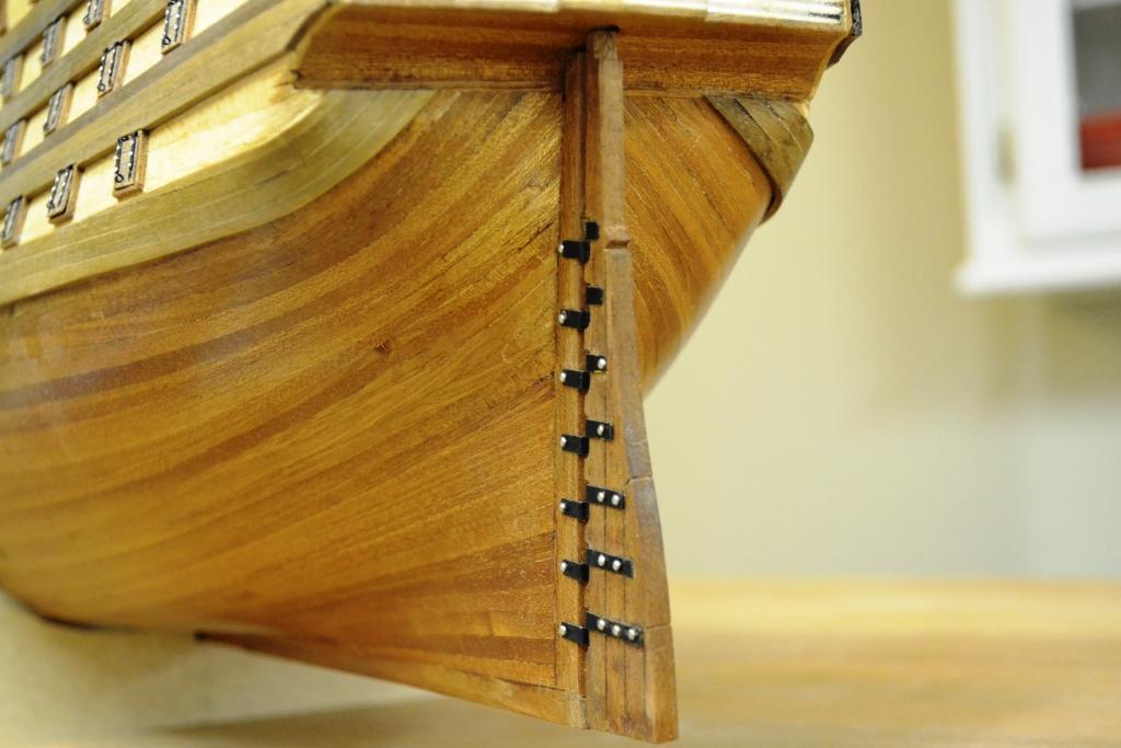
I installed the rudder today. Earlier in the build I “copied” the original supplied “plywood” rudder and used mahogany instead. First now I noticed that the hinges provided with the kit seems to be slightly too big for the cut-outs of the rudder (Yellow circle). Also the hinges do not have the correct shape (orange circle) according to the provided plans.. So first thing I did was reshaping the hinges so they became a better fit. A bit of a mystery: the plans only reveal to use 1.5mm brass wire to join the hinges (perhaps glue them together?) anyway I decided to use and solder brass nails to half the hinges . After cutting the nails in length I made the cut-outs in the ruder slightly bigger so they now easily could contain 1 complete hinge I did the following to the rudder to enhance some details: “angled” the rudder so it will work after installing cut some parallel lines in the ruder to simulate individual planks cut all the hinges in length so they were following the rudder shape blackened all the hinges And installed it.. Next are the side ladders, I noticed that some ships (like the victory) have a “side door” to enter the middle deck. Does anybody know if this was common on Spanish ships as well ? I’m considering to install it on my version of the ST