HOLIDAY DONATION DRIVE - SUPPORT MSW - DO YOUR PART TO KEEP THIS GREAT FORUM GOING! (Only 13 donations so far - C'mon guys!)
×

molasses
-
Posts
455 -
Joined
-
Last visited
Content Type
Profiles
Forums
Gallery
Events
Everything posted by molasses
-
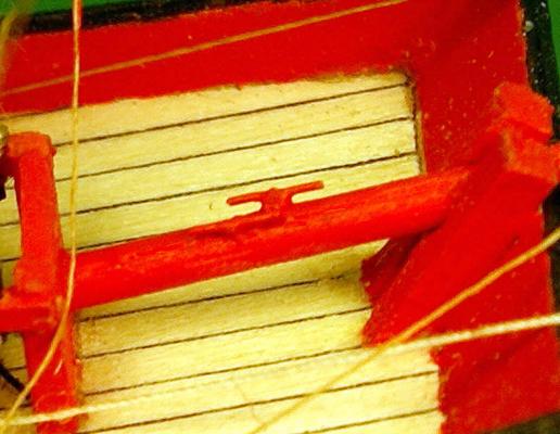
 This bottle had a screw cap (top dollar wine!) and the neck ID measures 1.025 in./26 mm.
 -
Thank you, Daniel, David and Augie. The kindness and support I've received during this project have kept me going when I was discouraged by setbacks and problems. In fact you've inspired me to do my best work instead of what I considered as good enough in a couple places. Thanks again, Dave
- 170 replies
-
- 1
-

-
- ogallala
- praire schooner
- (and 2 more)
-
Just plain help!
molasses replied to torpedochief's topic in CAD and 3D Modelling/Drafting Plans with Software
The kit I'm looking at is from Micro-Mark. It uses masks that can be printed on most computer printers and chemicals in the kit remove the un-masked metal. http://www.micromark.com/micro-mark-pro-etch-photo-etch-system,8346.html There's a link to how it works there. I don't know if Chief has this kit but it's the only one I've found. -
Just plain help!
molasses replied to torpedochief's topic in CAD and 3D Modelling/Drafting Plans with Software
I've been pleased with Serif DrawPlus Starter. It's a vectored drawing program rather than a drafting program which makes it easy to trace over an imported image then reduce the tracing to the size you need. I think it will suit your needs perfectly, I've been strongly considering a photo-etch kit and intend to use DrawPlus for the masks needed. -
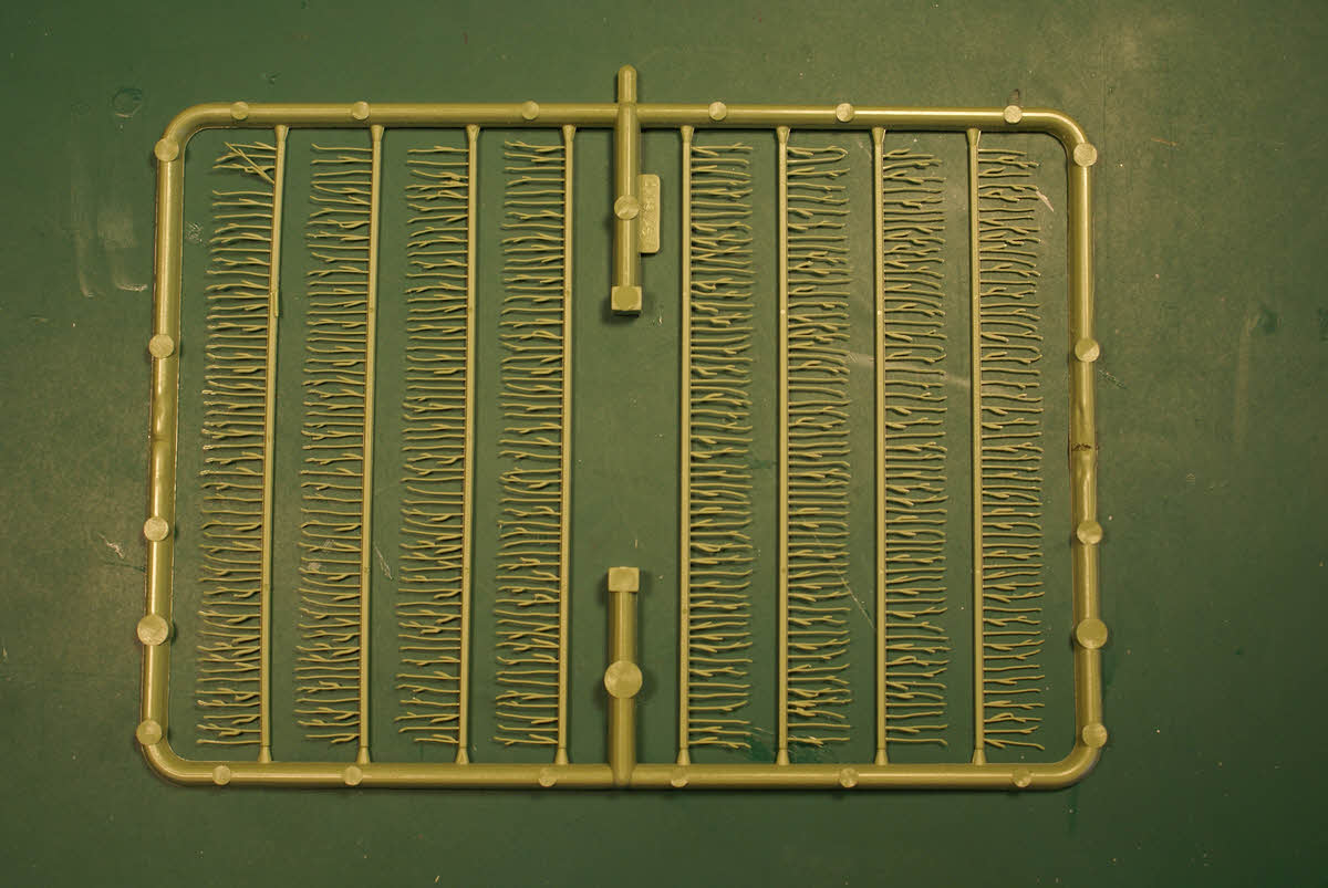
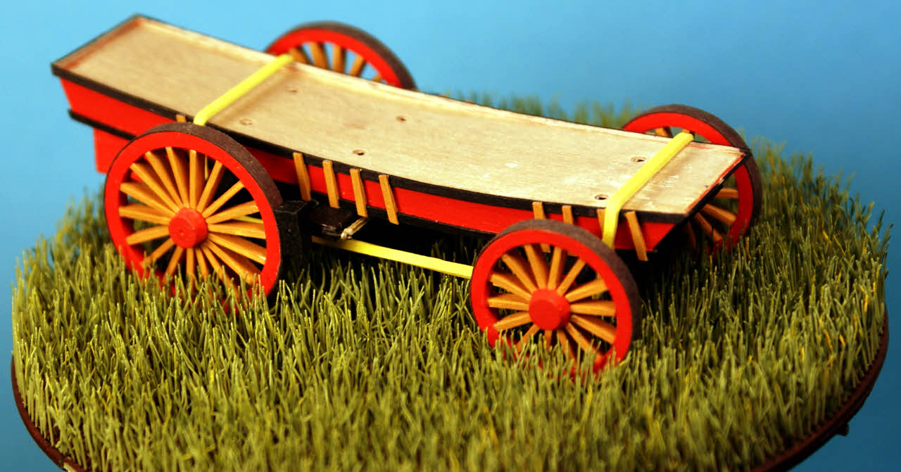
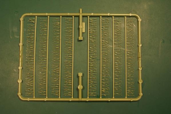
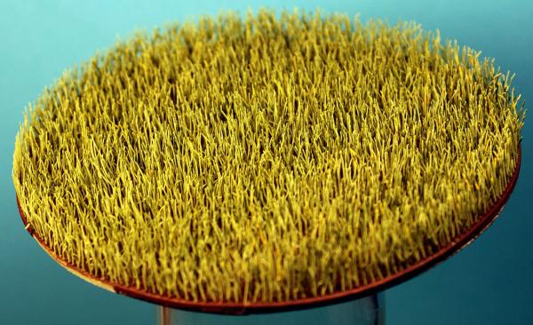
Here's my fourth try with my "sea of grass". To review, I selected an HO scale scenery kit for a field of barley and bought two of them - and a good thing, too. Each contained ten trees of eight strips. The strips are 4 in./100 mm long and .056 in./1.4 mm wide and assemble just like deck planks. The stalks are about .40 in./10 mm tall - about 40 inches/1 meter to scale and a close approximation of the short grass prairie of Kansas and Nebraska. A tree of "planks" of prairie grass. Being plastic, I tried gluing them to sheets of styrene but that didn't work; for some reason I couldn't discern these sheets of grass warped kind of like potato chips. I tried thicker plastic and it helped. For the fourth try I used contact cement to glue styrene sheet to 1/16th in./1.5 mm plywood. I detailed the strips and stalks - dark brown for the soil and darker green and pale green-yellow at random on parts of the stalks of grass. As I assembled the strips I bent and twisted most of the stalks to give them a more 3 dimensional appearance - about 5000 stalks!. The plywood and styrene base for the sea of grass is in four strips to fit through the opening of the sphere. I epoxied sections of brass tube to the underside of the strips for alignment with brass rods in three places. Here's the result. This disc of prairie grass is 4.5 inches/114 mm in diameter. I worked out exactly where the prairie schooner needed to be and flattened the grass in the wheel tracks and set the lower hull and wheel assemblies in place to see how it all looked. Lower hull and wheel assemblies (with a yellow rubber band to hold them together) posed on the prairie for a picture. The wheel tracks would show better if I photographed this at a higher angle - too late now. I still got a little bit of the potato chip effect but I think it's more a result of having one side of the plywood sealed and the other side not sealed and subject to abnormally high humidity. I live in a desert and three thunderstorms have passed through in the last week. Didn't get any measurable rain - it all evaporated before it hit the ground - but the storms did drive up the humidity from the usual 10 to 15% to over 40% and I'm sure it's temporarily warping the wood a bit. The "sea of grass" turned out to be more labor intensive than anticipated - especially with three false starts that used up most of one kit - but I think the result is worth it. Still working on figures and have detail work on the lower hull and wheel assemblies to finish before I can fit it all together inside the sphere. Dave


- 170 replies
-
- 9
-
-
- ogallala
- praire schooner
- (and 2 more)
-
This photo is associated with at least two different ships of the near 300 members (in two groups) of the Flower-class corvettes built just before and during WW2. This photo is most often associated with HMS Balsam, a member of the group of Modified Flower-class (69 vessels) ordered by Great Britain in and after 1940. The exact count of the number built is somewhat difficult to pin down because they were built in British, French, Canadian and US shipyards and they served in all four navies and in the navies of six more allies. Many were freely swapped between the USN, Royal Navy and Royal Canadian Navy under lend-lease agreements. Some Canadian built ships served in US waters with USCG crews in preparation for US entry in the war. Four were captured by the Nazis on the ways in France and three of these were completed and served in the Kriegsmarine. Those that served in the US Navy are known as Temptress- and Action-class gunboats. The Flower-class accounted for fully half of the convoy escort vessels deployed in the North Atlantic during WW2. HMCS Sackville is the only one of the class preserved as a museum ship. One source says 267 were built but in the same article says 225 in the early group and 69 in the modified group (294 total). Also, do the 3 completed by the Nazis count? Anyway, David's mention of Flower-class was first. It's up to SpyGlass.
-
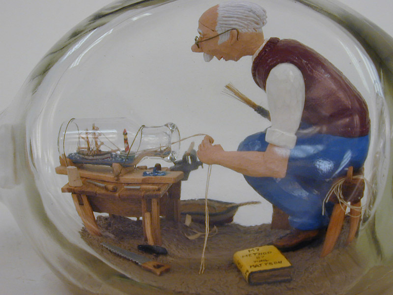
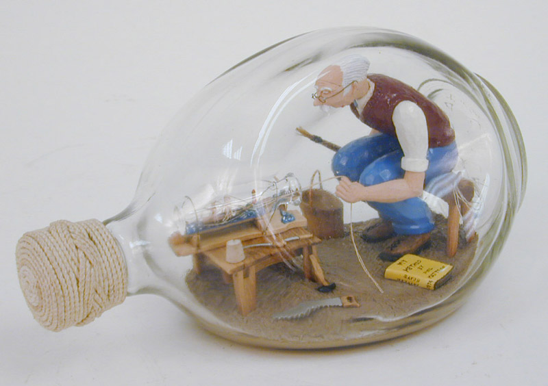
I like this micro miniature a lot. It turned out well considering the limitation of a bottle about the size of a thumb and that it is almost entirely an experiment in new techniques. I especially like the furled courses as if she had just engaged her latest victim - and it fits with the bit of "battle damage" Daniel pointed out. Well done, Daniel.
-
Thank you all for your kind and generous comments. I can't help but focus on the flaws and defects in my work, it's apparently in my nature and always has been. It's only when I've been away from the bench for a while and return to work on this project that I get a brief "Wow" moment before the deficiencies start jumping out at me. Jeff, the shininess is entirely a camera/lighting effect; the finish is matte by eyeball. I've started the next three figures and I'm sure they'll be better. I need to figure out a quicker way to make armatures before even considering doing a minimal crew (say, 20) on deck for a "real" vessel. Perhaps photo-etch stick figures for a model at 1/300 to 1/500 scale. Speaking of 1/500 scale, Michael, I admire very much the start you made on the miniature pilot cutter. I hope you get back to it. Dave
-
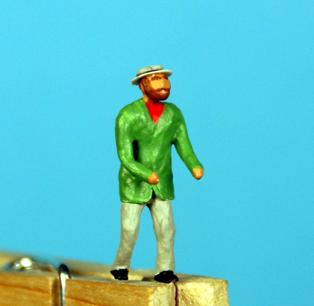
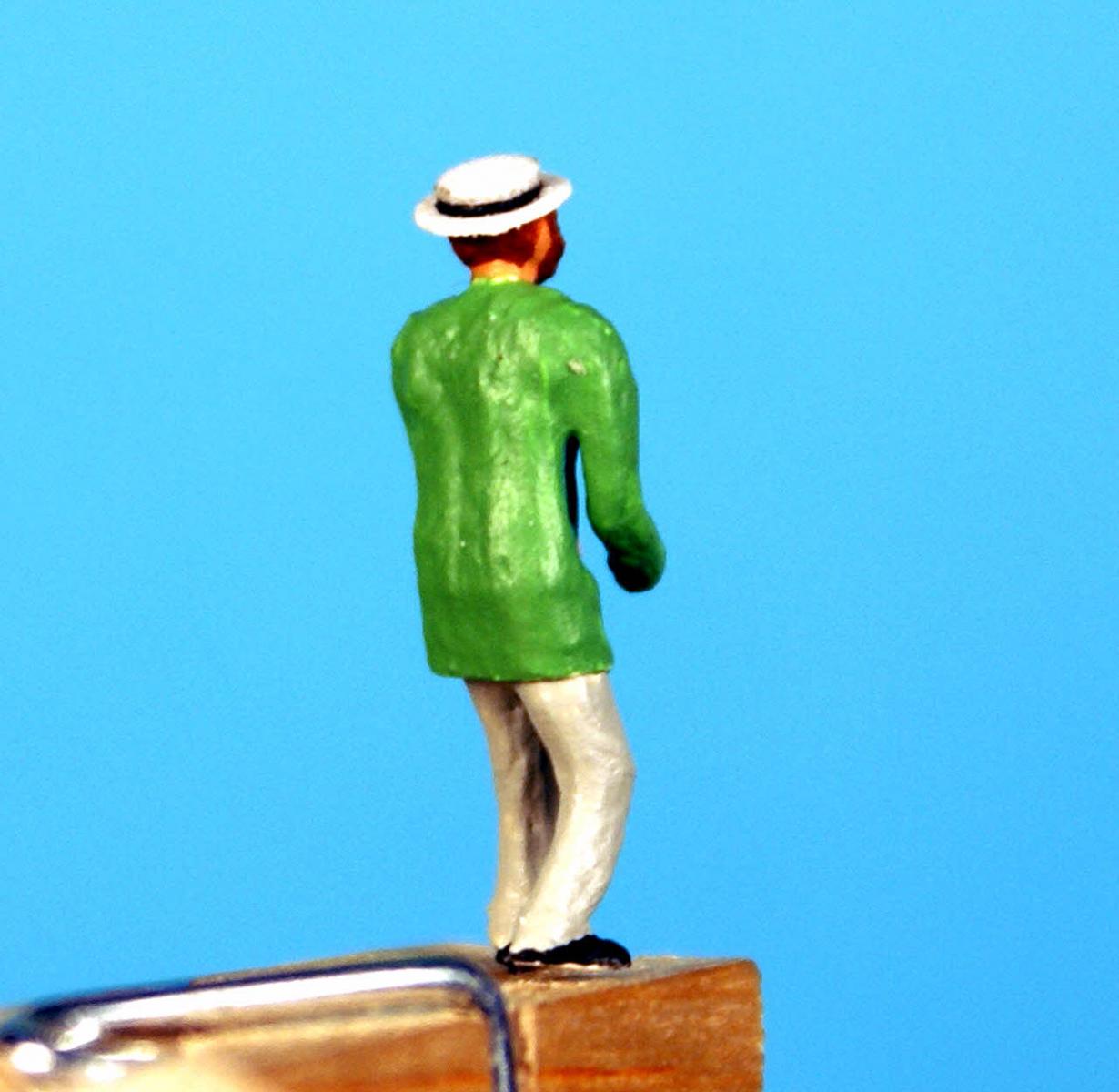
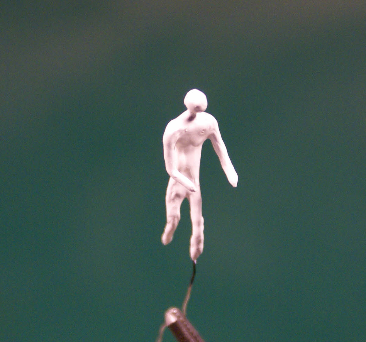
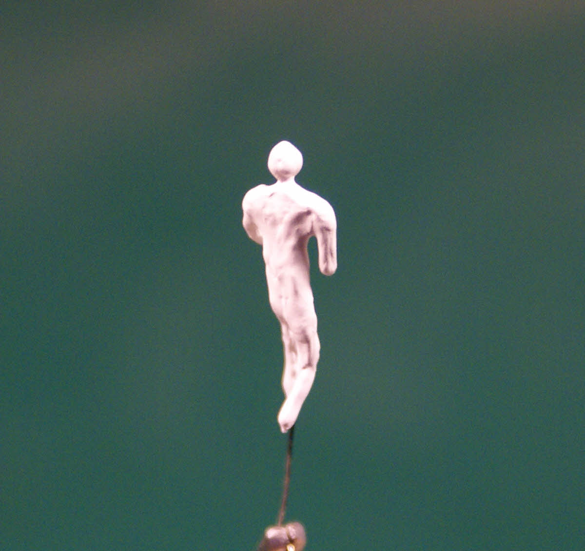
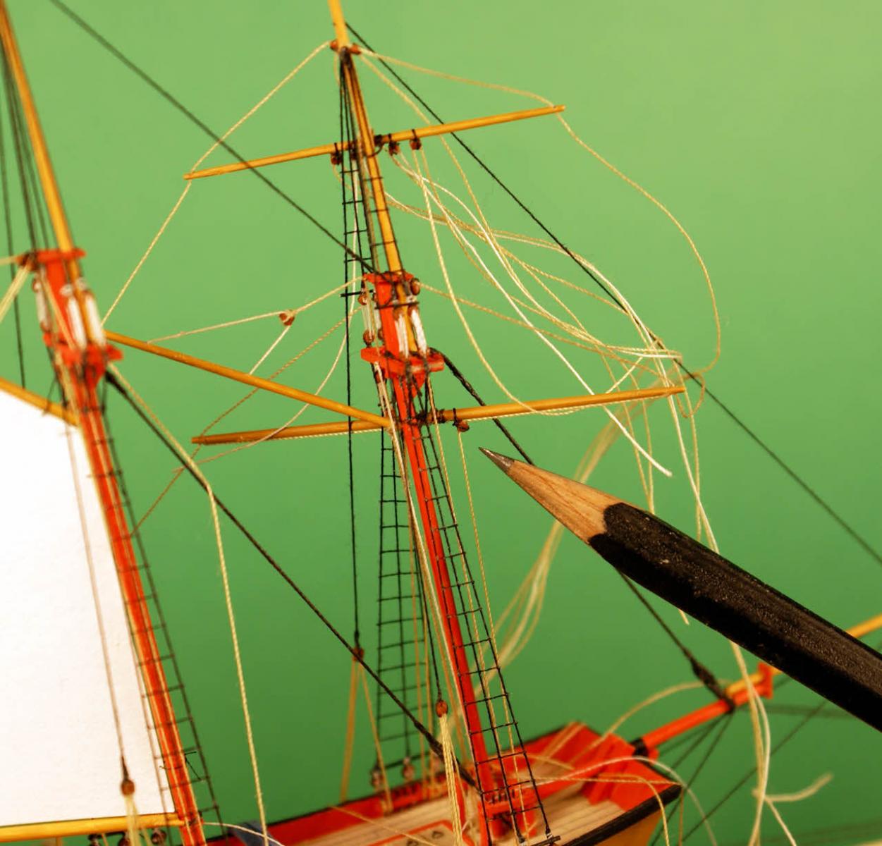
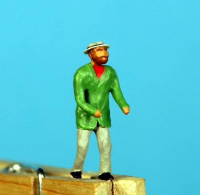
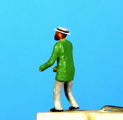
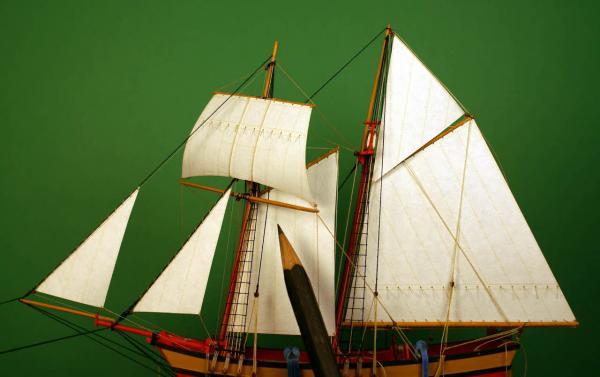
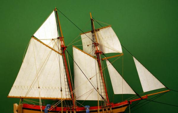
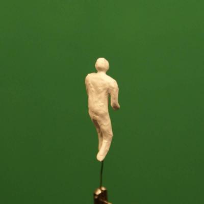
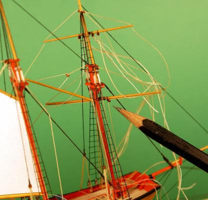
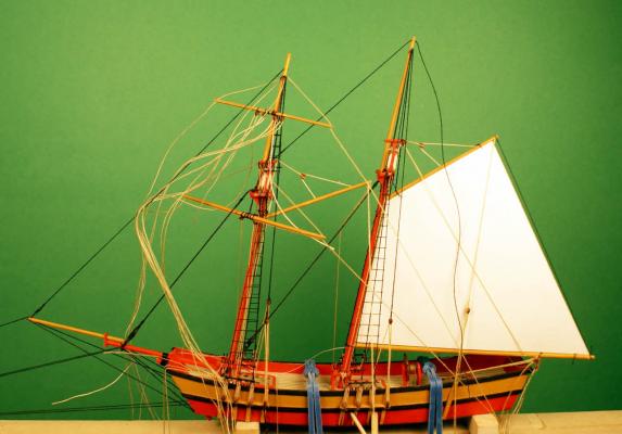
Closer to 40 tries than 20, Michael. Shows you how extreme my obsessive/compulsive disorder has become. Finished the rigging that I can tie off before bottling the model. Larboard view with a pencil for size reference. Starboard view. Gaff foresail extended away from the model to tie the sail to the gaff. This sail will get in the way when the mast hinges for going into the sphere so will need to extend similarly. It has nine lines that will need to be adjusted and glued when inside, perhaps less - I'll know for sure when I drop the masts to bottle Ogallala. I needed two blocks for the peak halliard and the gaff topsail up haul and decided to combine them into a violin block just to keep things neat and tidy. I needed a pair of cleats, smaller than the first batch, on the bowsprit for the stay sail and jib down hauls. They were made from 36 gauge wire (.008 in./0.20 mm) bent in an "L" about .040 in./1.0 mm both legs. I glued one "L" into a hole then drilled a second hole next to it and glued a second "L" into it. I decided I needed tackle to pull the foot of that big mainsail taught along the boom and a pair of cleats to tie off to. These cleats were made the same way but smaller with the "L" pieces at .030 in./0.75 mm each leg. They are about two-thirds the size of the wooden ones I made earlier (two visible on the bulwark) and easier to make. I hadn't planned to be as complete with the rigging as I've been since I started on it. I haven't done the topping lifts and reef tackle for the fore topsail and the leach lines for the two gaff sails (and a couple other minor lines) simply because I don't have enough places on the pin rails to tie them off. I have coils of rope to prepare for each belaying pin (matching the color tied to it), paint touch up and some other minor detail work on the upper hull to complete. I'll do much of this to fill in bench time while focusing most of my attention on other aspects of the project. My "fill in" work while rigging Ogallala was my test figure, the first of three or four to make. I got him finished and I think he turned out okay. My helmsman wearing a green jacket, gray pants, red shirt, black shoes and a straw skimmer. He's .685 in./17.4 mm tall - smaller than an HO railroad figure - 5 ft. 9 in./1.75 m to scale. The hem of his jacket is a narrow strip of paper wrapped around him to make it look more realistic than just building up with gesso. It also conceals my mistake in making his torso a bit too long. I found that the front lap and lapels can be simulated with brush strokes of gesso carefully applied. Larboard quarter view. If you look carefully you can see where I didn't quite blend in the gesso to the paper hem. I changed the background color to light blue for contrast with his green jacket. He looked too much like a head floating above gray pants with the green background. Starboard quarter view. I can't figure out why his jacket and pants have highlights as if the paint was gloss rather than flat. Perhaps the color correction I applied enhanced them. The straw hat was made from discs of ca treated paper glued together and glued to his head after I cut the top of his head off flat. I painted the edge of one disc black for a hat band before gluing them together. I think I need to add one disc to the top of the hat. I'm not entirely pleased with my first human figure - he's no better than "good enough" - but I am encouraged by the result and what I learned to try three more. I have some detail work on the lower hull and wheeled components to do. I need to get to work on a second try with the sea of prairie grass which will be my primary focus. Not really applicable to ship modeling so I won't go into a lot of detail when I report on it. Then I'll be ready for the part I find most stressful - bottling it. Dave


- 170 replies
-
- 10
-
-
- ogallala
- praire schooner
- (and 2 more)
-
Thank you, Bob and Piet, but I'm not sure "magic" is the right word - unless you're using it as a euphemism for "product of insanity". Much of this project is trying to do something I thought was crazy to attempt but did anyway - and, to my surprise, they worked. I'm glad you're aboard.
-
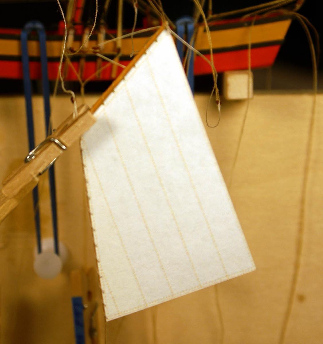
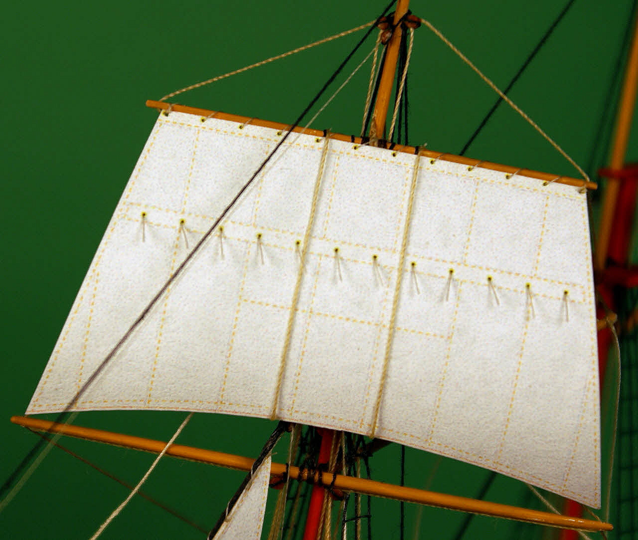
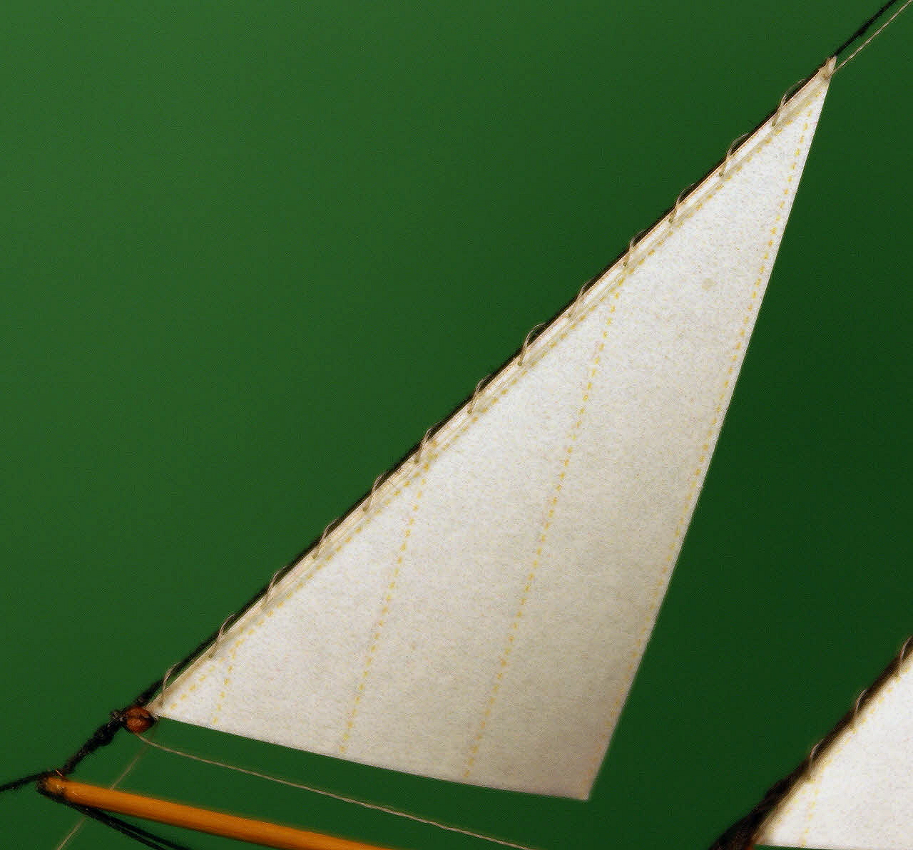
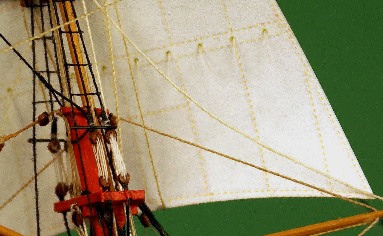
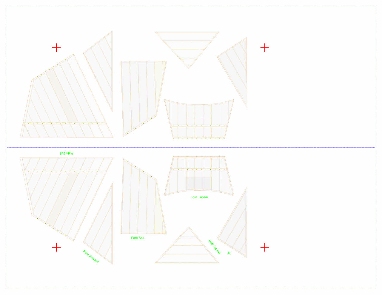
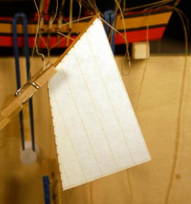
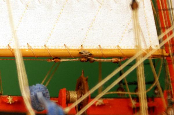
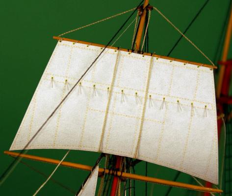
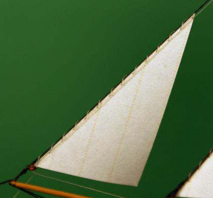
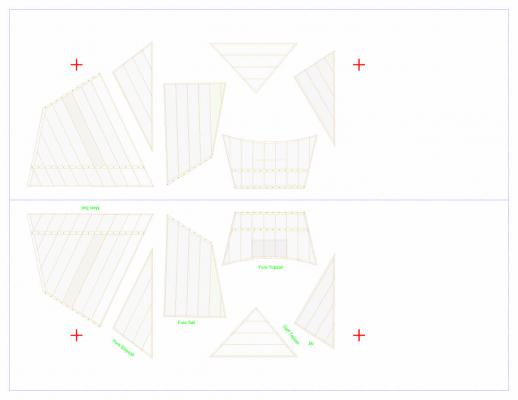
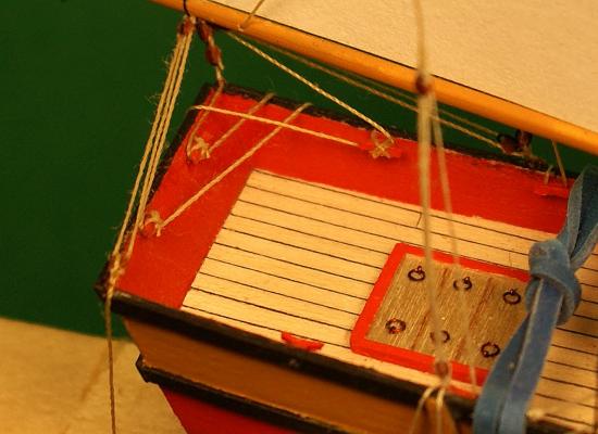
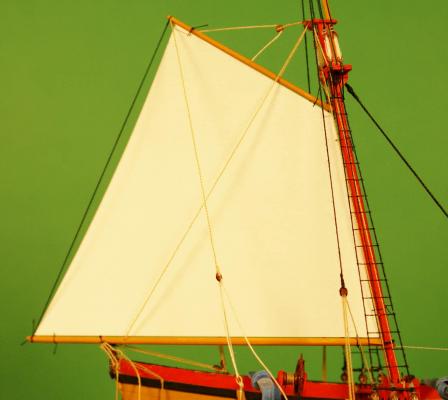
Welcome. Spent several hours on the computer redrawing the sails based on my card stock templates made to verify size and curvature then detailing the drawings with seam edges, stitching, patches, reef bands and brass colored grommets. I then mirrored those sails and detailed the opposite sides to match. Sail printing computer master. I used four shades of light grey and two shades of light tan to simulate differing ages, thicknesses and production lots of the canvas. This image was printed on both sides of a sheet of paper to print two sets of sails. The red crosses and the blue centerline and border served as register marks to check that the images on both sides align to each other. I stopped counting at about twenty tries and estimate that it was at least thirty print-outs before I got one sheet with two sets of sails where the variables in paper feed starts, slight angular shifts of the paper during printing, etc. resulted in one "perfect" set of sails. I used the best grade of 20 lb. printer paper with the smoothest surface finish I could find. After cutting out the sails I drilled the holes at attachment points rather than poking holes with a needle point which promotes tears in the paper near edges. I also drilled the holes for the reef point ties. Fore topsail bent to the yard with the reef point ties in place and the buntlines finally rigged. Notice the stitch line below the reef band across three clothes for the wear patch on the other side. The sail is 2.015 in X 1.140 in (51 mm X 29 mm) since I forgot a size reference again. Aft side of the topsail. Here you can see the wear patch in a slightly darker shade of gray, a buntline and a clew line with an appropriate caternary to the corner of the sail. I made up some blocks at .032 in (0.8 mm) diameter for some of the sail control lines on the staysail and jib and bent the sails to the stays. Jib with a block and rope for the downhaul. I still need to rig the sheets at the corner. The block and rope for the uphaul is visible just below the stay in the first photo of the topsail. Dave


- 170 replies
-
- 8
-
-
- ogallala
- praire schooner
- (and 2 more)
-
Thank you, Jeff. Learning from each other for the benefit of all is the whole point of this website. Ship modeling has perhaps the longest and initially the steepest learning curve of any hobby and anything that eases that curve is a good thing. I feel like I've learned more in the year and a half since finding this site than in my decades of ship modeling that passed before. I'm very pleased that I can help others. I didn't mention it when I installed the belaying pin rails at the masts and on the bulwarks but they are all pinned at their attachments. The pinrails at the masts are also pinned through all the joints. I did this not so much for the stresses of the finished static condition but for the sudden, accidental loads that can occur during building - and everyone who has built a sailing ship model knows about those.
-
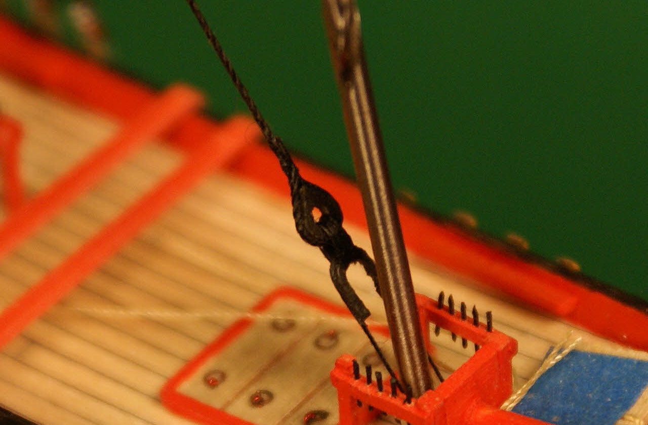
I absolutely cannot have any of those cleats coming off inside the bottle, they would be just short of impossible to repair. By pinning them with .012 in/0.30 mm diameter X .030 in/0.75 mm (stick-out) steel bug pins I'm able to provide about 2.5 times the glue surface over the .020 in/0.5 mm X .040 in/1.0 mm base of the cleat plus the steel reinforcement of the connection. No worries about the cleat failing unless it breaks apart from around the pin. The extra work is cheap insurance against a near disaster and the pins provide convenient handles for painting the cleats.
- 170 replies
-
- 4
-
-
- ogallala
- praire schooner
- (and 2 more)
-
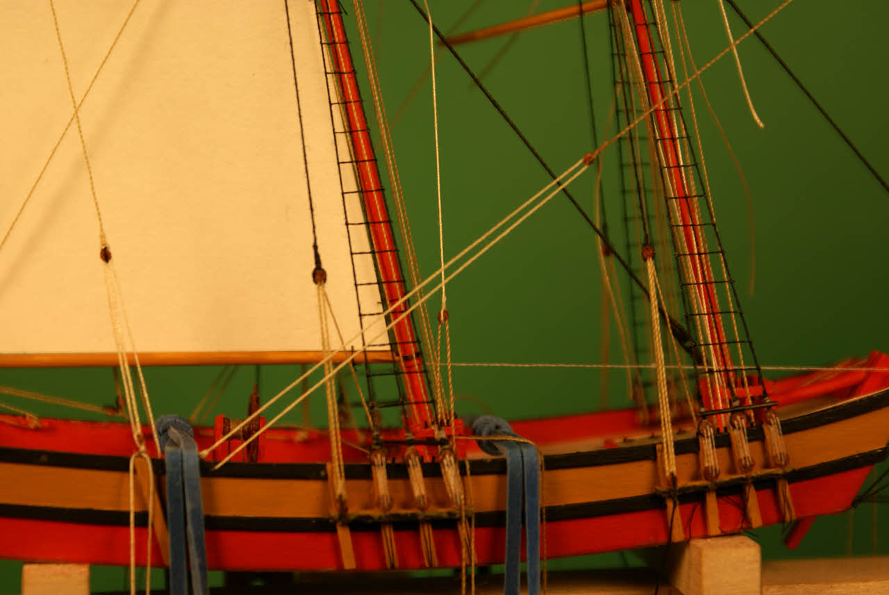
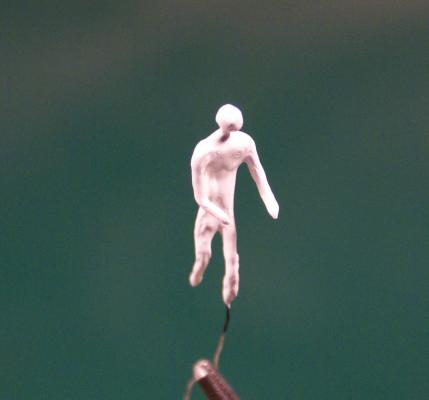
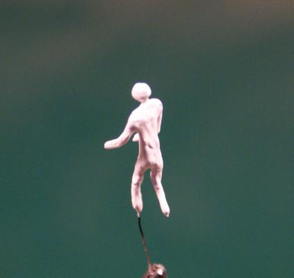
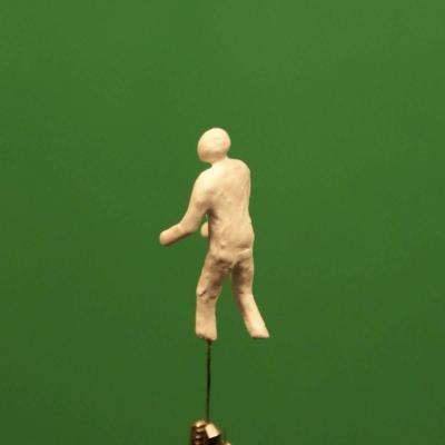
Thank you, Piet and Bob, and the likers and lurkers. I don't mean "lurker" at all derogatorily - I "lurk" several builds and topics myself. Worked on some odds and ends. I started with some cleats. Cleats ready to install. They have a piece of bug pin through them for strength when glued to the bulwarks. Some of the cleats glued into holes and rigged. The crossing ties on the cleats are fakes. The lines to the cleats will be glued when inside the bottle and trimmed close to the cleats. Then I finished the foremast yard braces and foresail gaff vangs. Upper portions of the braces and vangs. Lower portions of the braces and vangs. The remaining rigging will be finished when the sails are installed. I also worked on my trial figure by building it up with some more gesso to the point where I can try to detail it. I discovered that the cured gesso is flexible, almost rubbery, and I can adjust the pose, which may be a blessing - or a problem. I didn't test it to find out how much flexing it will take, maybe later if I don't like the finished figure or replace it with another after some practice making three more figures. A photo I posted a while back for comparison to the more "filled out" current condition. A pair from his larboard quarter. I trimmed the legs and will add feet below the cuffs of his pants. And from his starboard quarter. It seems my photography has improved somewhat in the interval. Dave


- 170 replies
-
- 9
-
-
- ogallala
- praire schooner
- (and 2 more)
-
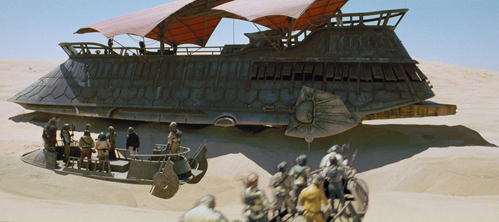
Resembles Jabba's sail barge from Star Wars VI

-
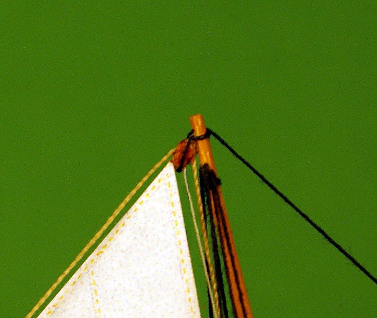
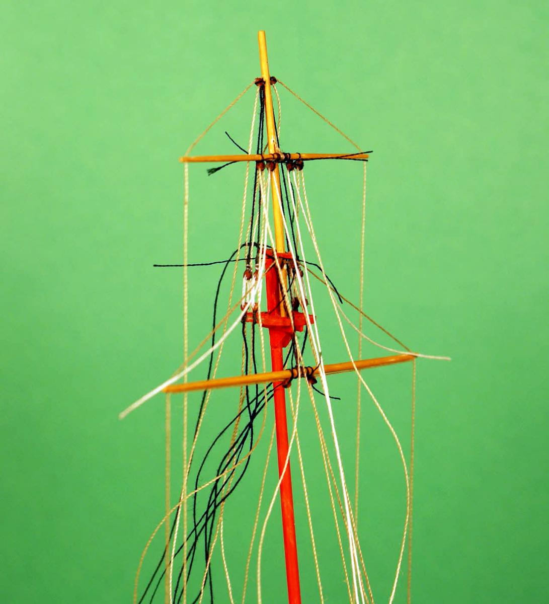
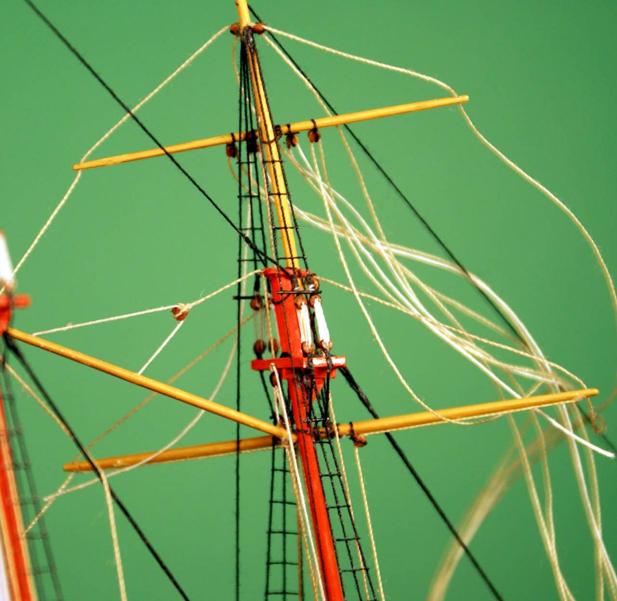
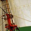
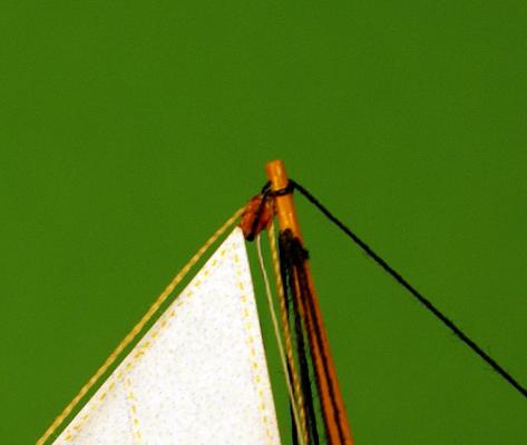
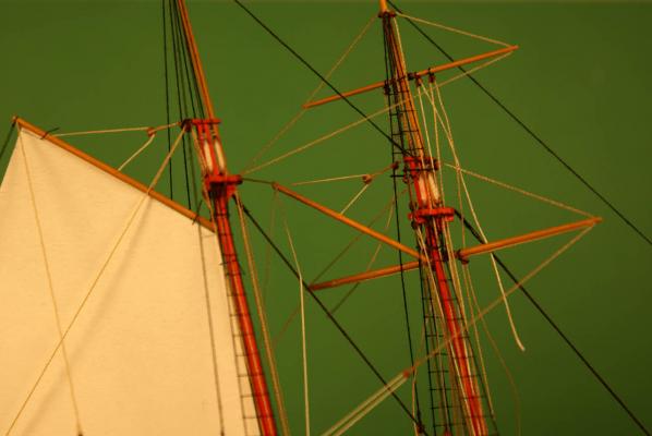
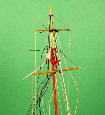
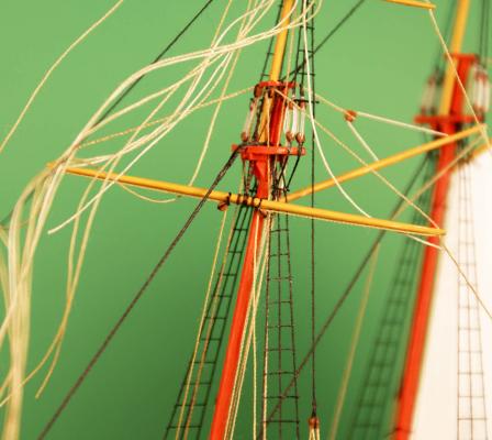
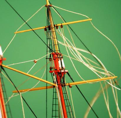
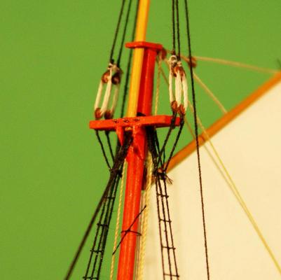
Welcome back. Worked mostly on foremast rigging. Since most of this work is repetitious of the mainmast rigging I won't go into the details of how it was done. Foremast with most of the rigging - and looking like a birds nest. It's easier - and safer - to rig as much as possible of the mast off the model. I took this photo right after stropping all the blocks while waiting for the glue to cure so I can trim all the loose ends. Foremast in place with the standing rigging and ratlines rigged. Also in place are the gaff with throat and bridle halliards and vangs. The bird's nest is slowly being un-tangled with lines going down to the deck and tied off to the pinrails. Close-up of fore topmast, gaff, crossjack and topsail yard. You might notice that the topsail yard and crossjack halliards pass through the tips of the yards to become the respective braces. The lines are not glued at the tips, only at the mast. This arrangement allows the yards to rotate to a position more parallel to the mast after the mast is hinged down to the deck for fitting through the bottle's neck. Another view of the crossjack and top. Note that the running rigging is in four shades of tan to simulate varying states of wear and weathering. I still have the topsail yard halliards and the topsail clew and buntlines to route to the deck and tie off. That will leave the other ends of the clew and buntlines left hanging until I bend the topsail. Overall view of the progress so far. I didn't forget the ratlines on the main topmast shrouds, I left them off because they were frequently omitted on schooners like this. I also have the fore braces and vangs to rig. Dave

- 170 replies
-
- 11
-
-
- ogallala
- praire schooner
- (and 2 more)
-
Thank you, Bob. Coming from you it means a lot to me. Thank you, Jeff. My photography gradually improves as I learn from practice and occasional tips I receive. I'd like to improve my depth-of-field in the close-ups but a smaller aperture requires more light or longer exposures. So far my experimental photos haven't turned out well - I'm still pretty much an "all auto" photographer.
-
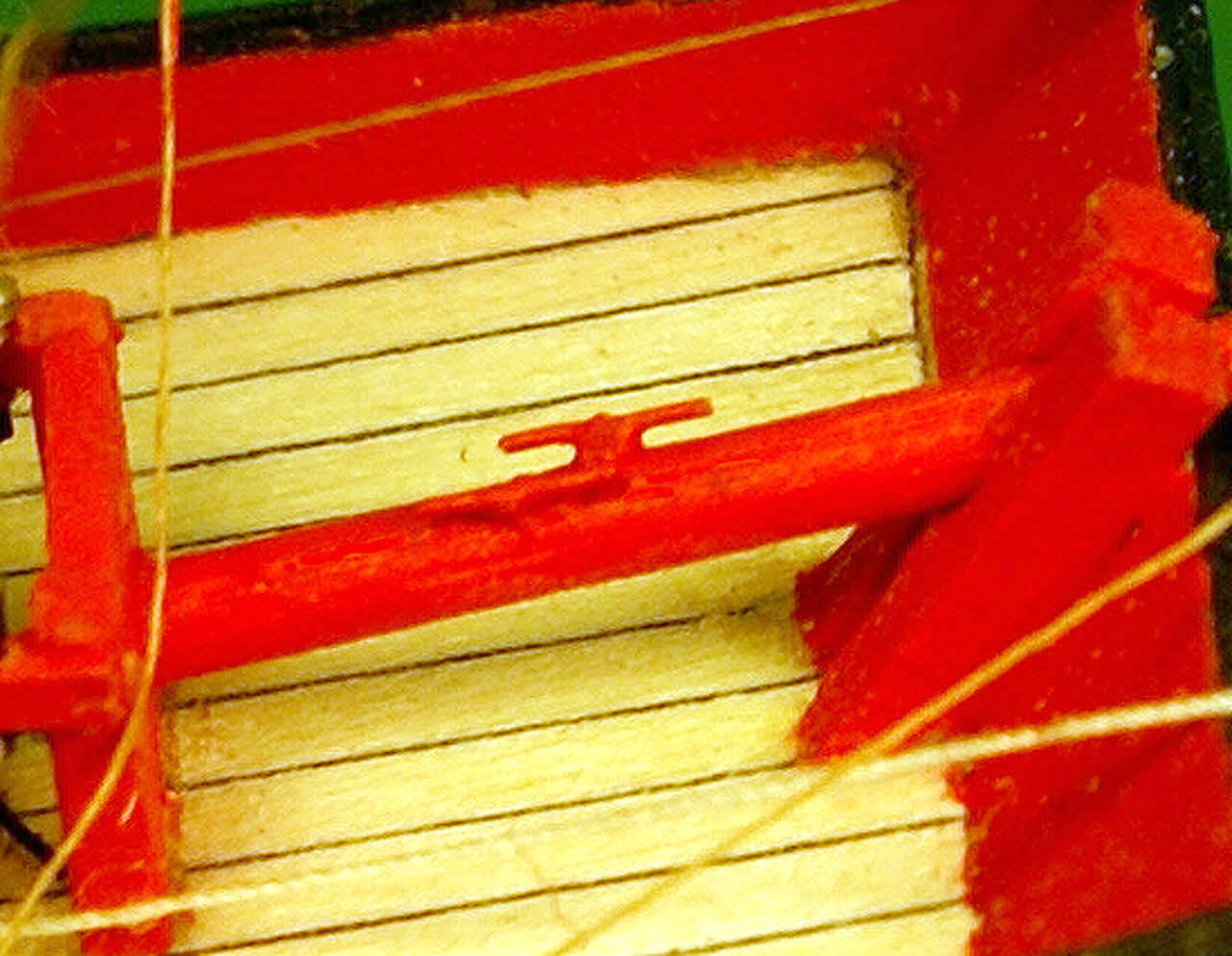
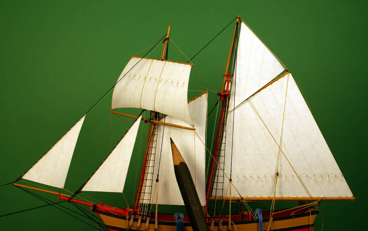
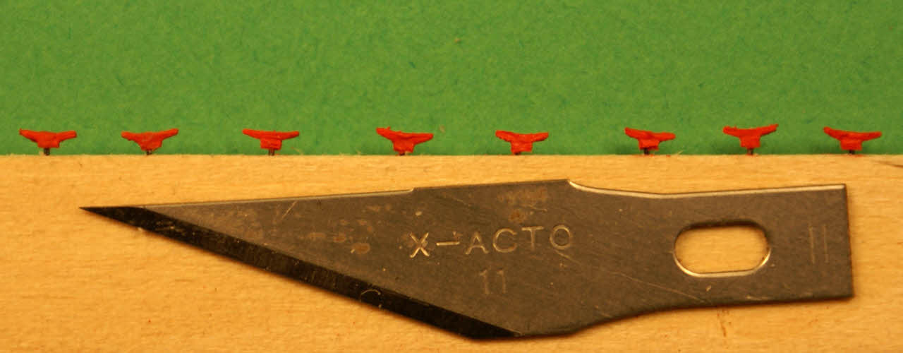
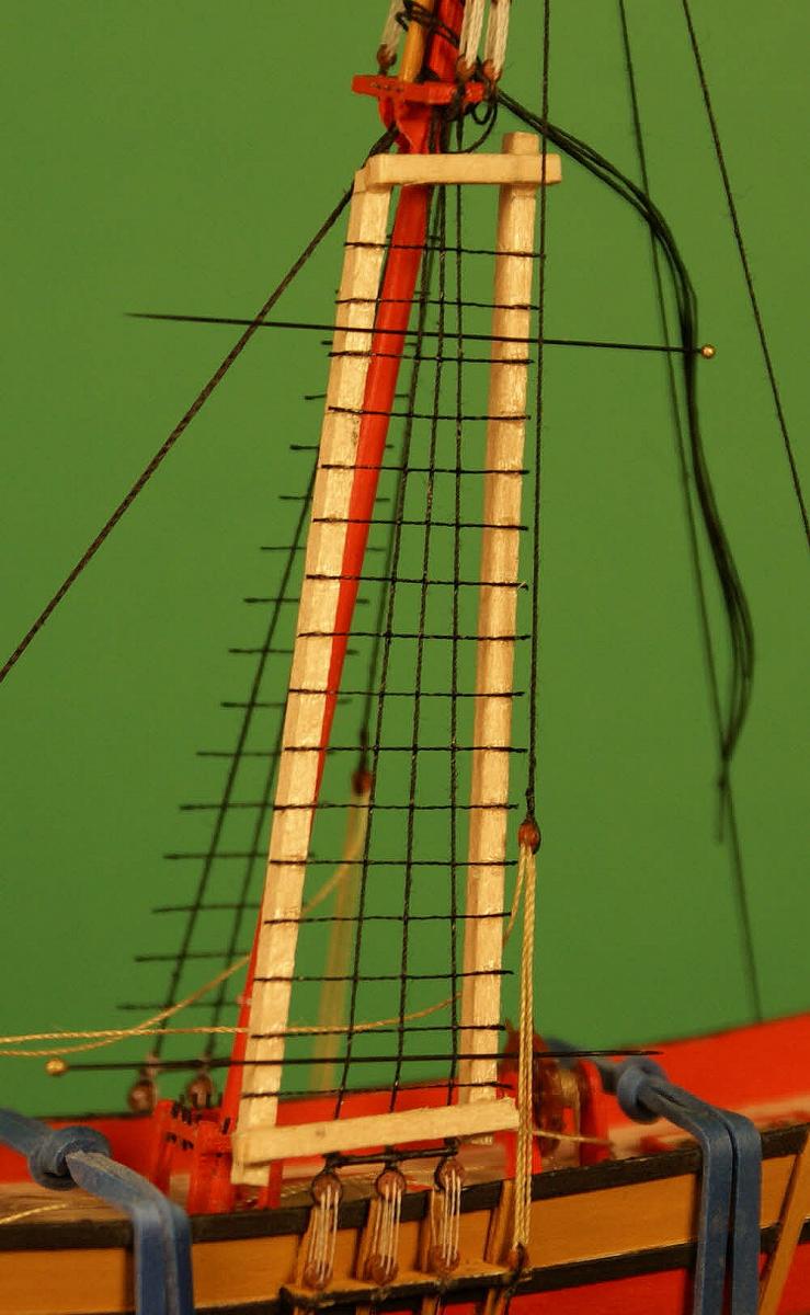
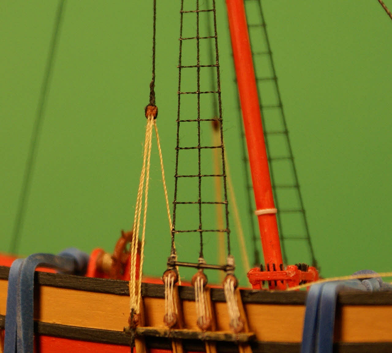
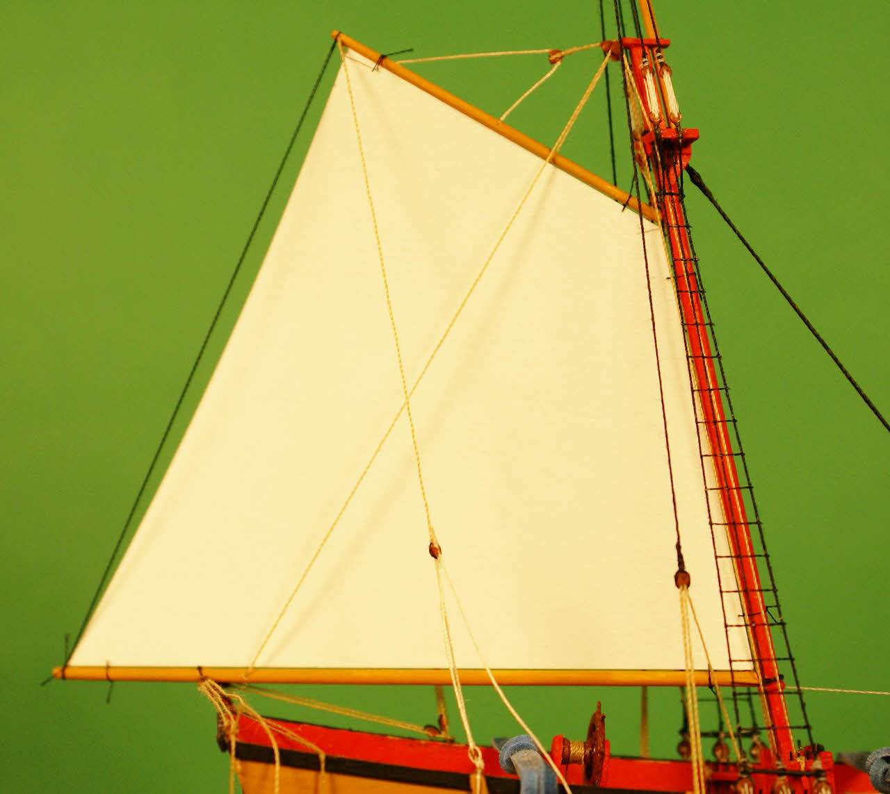
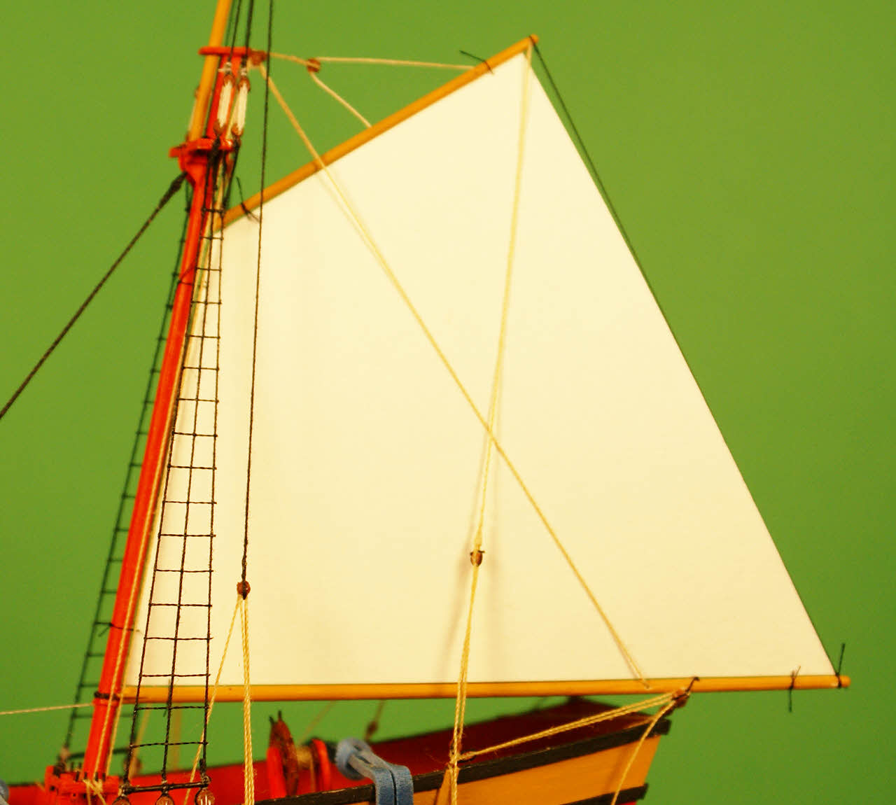
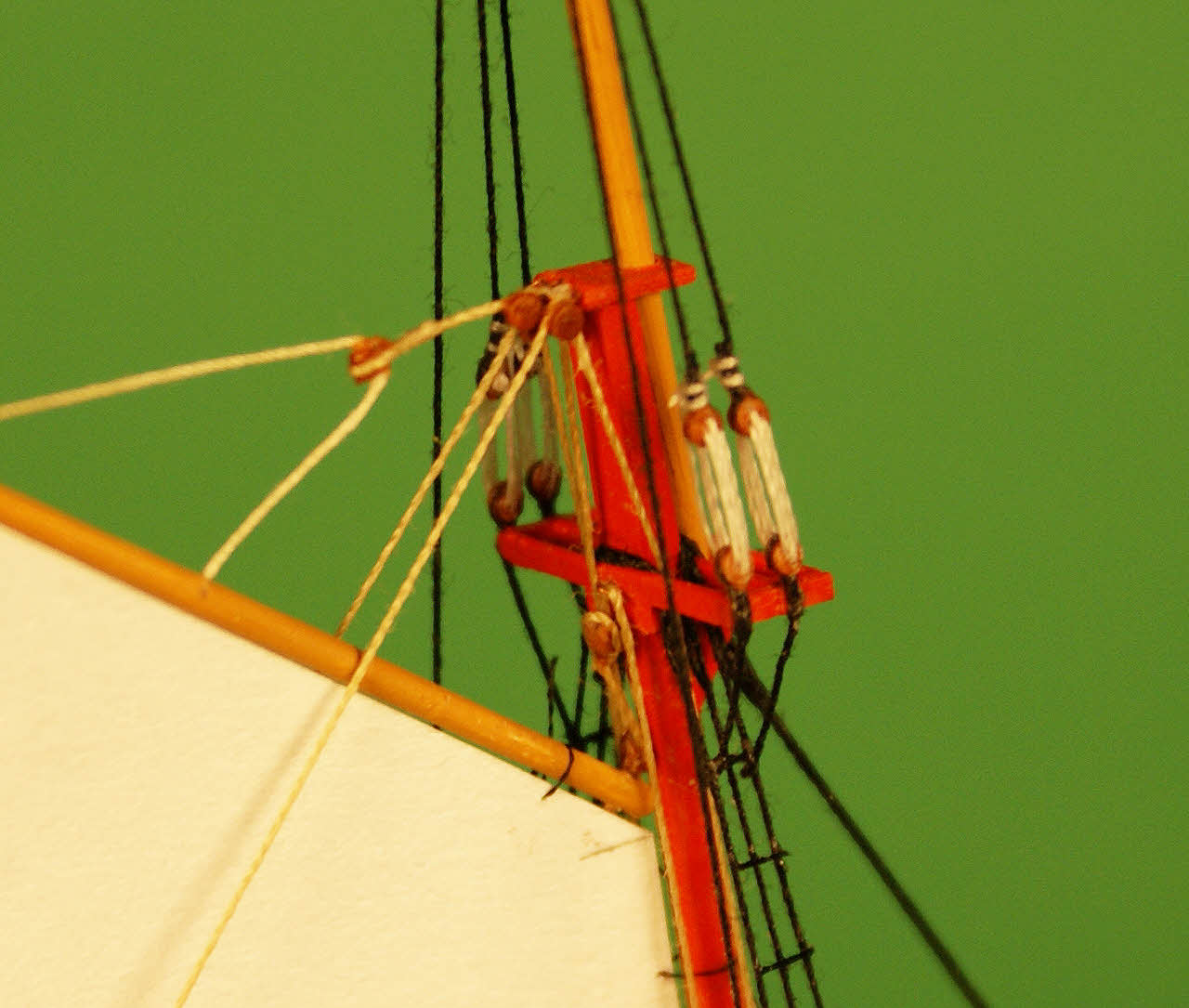
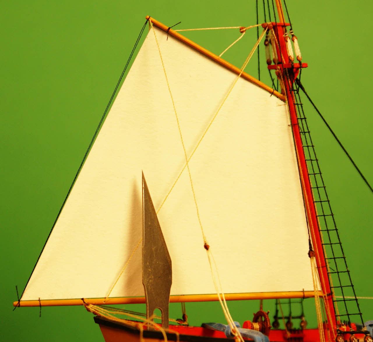
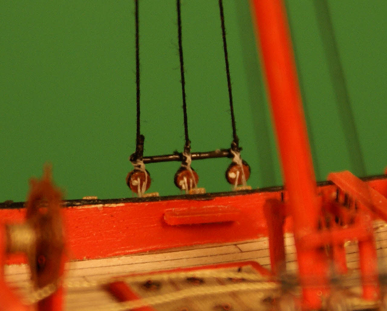
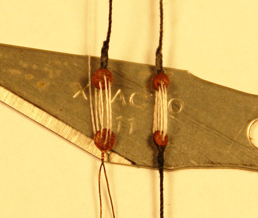
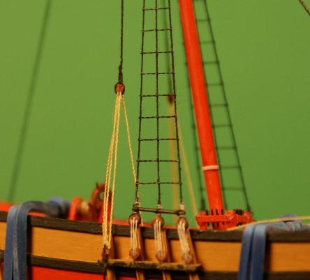
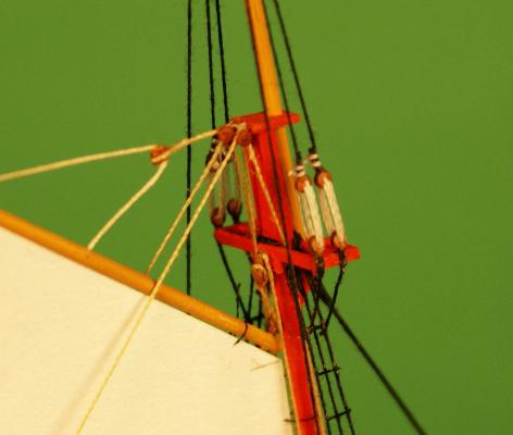
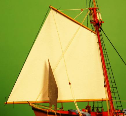
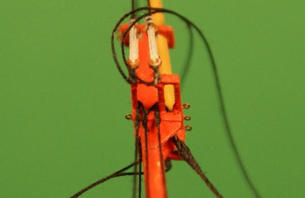
Welcome back. Thank you, Jeff and Michael, you are both very generous. BTW, I proudly stole every one of "my" techniques - thank Donald McNarry and Lloyd McCaffery for many of them. I started with the breast backstays, each rigged with a single and double block. After choosing the length of the tackle from outside to outside of the blocks I routed the thread between two pins in drilled holes in a scrap of wood and built the tackle using the discs as previously described then needle spliced an eye around each block and added the backstays to the model. I rigged the main ratlines using a "harp" with ratlines spaced and glued to wooden frames. The frames were opposite hand, one for each side of the schooner. After pinning the frame in position with bug pins I glued all the intersections. I'm trying out artist's matte acrylic fixative instead of thinned white glue and am pleased with the results. The white glue sometimes goes milky while the fixative stays clear. I thinned it a little by using a wetted brush when I dipped it into the fixative. "Harp" pinned in place with intersections fixed and frame ready to cut from the ratlines. Starboard side has the harp removed but the excess on the ratlines un-trimmed. Breast backstay and trimmed ratlines. The backstays go through the same hole where the topmast shrouds were secured and are now tensioned with weights. The backstays need a bit of adjustment before they glue. After this photo I rigged the futtock shrouds and futtock staves then glued and trimmed the backstays. Starboard view of the mainsail, spars and rigging. While assembling this I had a card stock sail in place, tied to the boom, mast and gaff to hold them in their correct positions. This card stock sail has been lengthened slightly along its leech (aft edge) to give the belly I want in the sail. The aft ends of the boom and gaff have a thread to pull that belly in this temporary sail. Larboard view. The card stock sail will be removed later to use as a pattern for making the sail. The black line will be removed before the sail is installed. I have some cleats to make and install where the leads from the blocks and tackles will tie off which explains some of the stray threads. Close-up of main top showing the futtock shrouds and futtock staves. I used a needle to pass each futtock shroud through a lower shroud, glued it (not ca) then passed the needle through those intersections, sideways, for a third thread to be the futtock stave, glued it and trimmed. Close-up of main top showing the boom and gaff halliards and gaff throat halliard. After making and installing the throat halliard and installing the gaff I routed the throat halliard and the boom and gaff halliards through eyebolts installed while building the masts. The blocks for boom halliards were made in place. The block on the gaff bridle halliard at the eyebolt was glued prior to rigging to act as a stop while rigging. All four lines continue to the deck. Close-up of pin rail where the halliards tie off. I installed eyebolts earlier for the gaff halliards to route through so that some of the tension on the pinrail is downward to balance the upward pull by the boom halliards tied off there. Tensions are very light - just enough to hold the line straight - but I felt it necessary to do this. You can also see where one of the breast backstays tied off to the pinrail on the bulwark just below the shrouds. A white thread from the throat of the boom, through the mast and out the bottle for pulling the boom into place is also visible but mostly out of focus. I almost forgot a size reference but recovered with a standard #11 X-Acto blade. As always, click on a thumbnail shown here for the larger format photos. Thank you for viewing this log. Dave


- 170 replies
-
- 11
-
-
- ogallala
- praire schooner
- (and 2 more)
-
Thank you, Piet, sometimes I amaze myself when I take off my Opti-Visor and see the real size of the work. The first one is always the most difficult but I use lots of little temporary fixtures made with scraps of wood and bug pins. It's really not much different from the rigging most of you guys do - just smaller - and I don't have to serve it. I swung up the yards on the foremast but decided to finish the mainmast standing rigging including the ratlines and rig the boom and gaff before installing and rigging the foremast. Back in a couple days. Dave
-
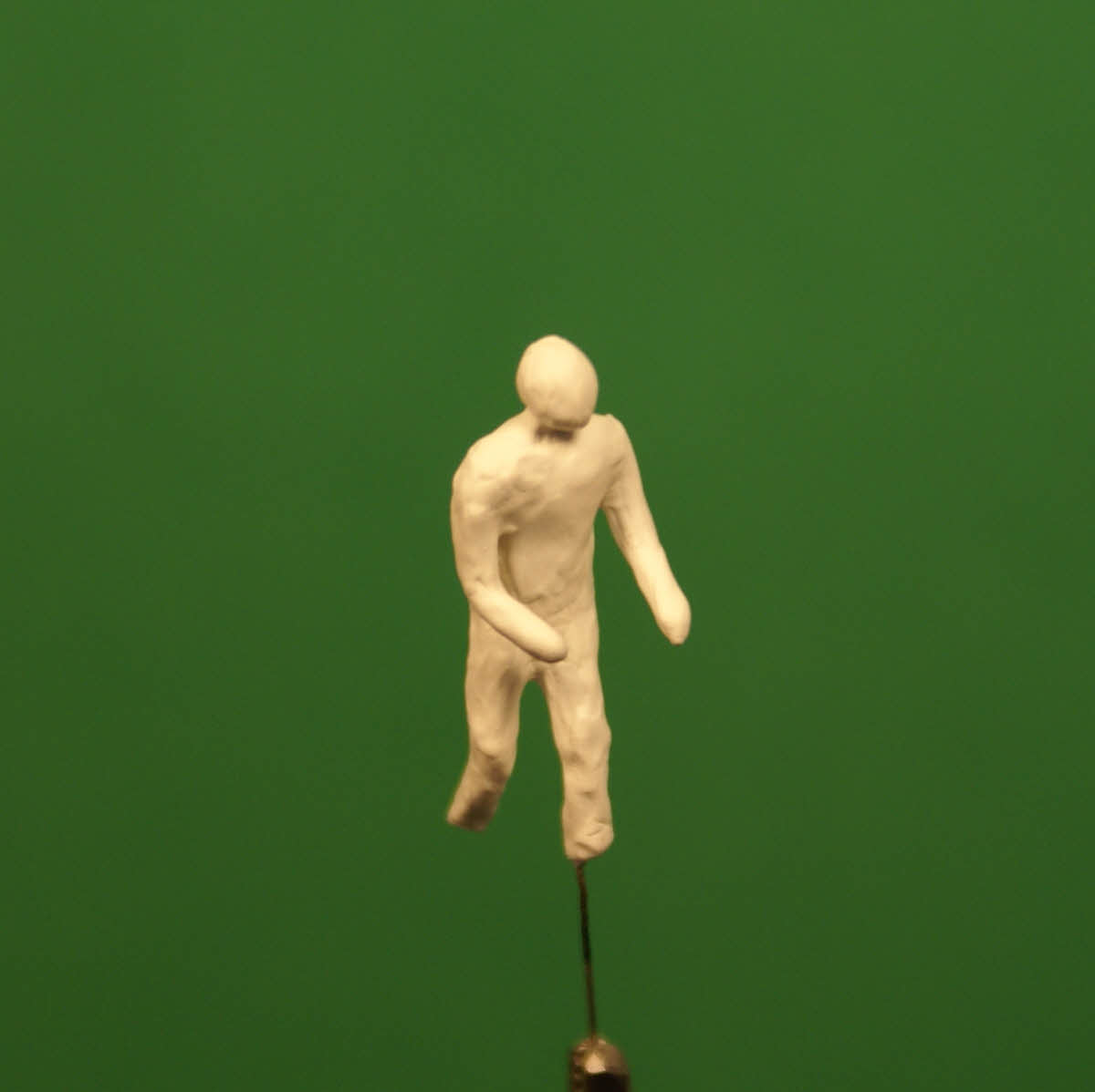
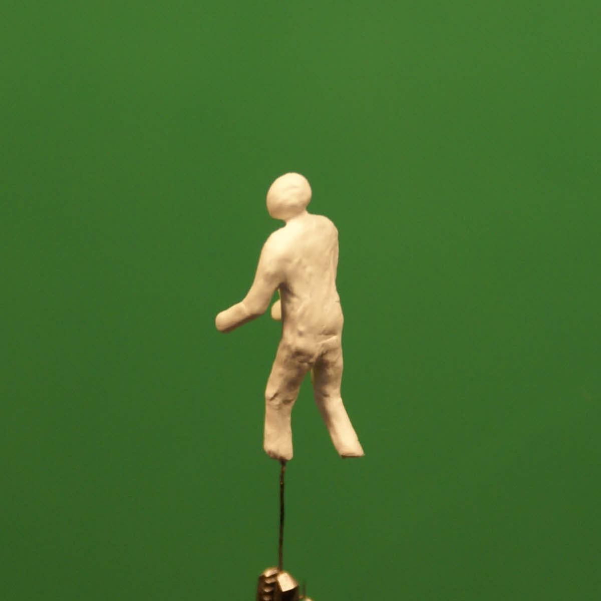
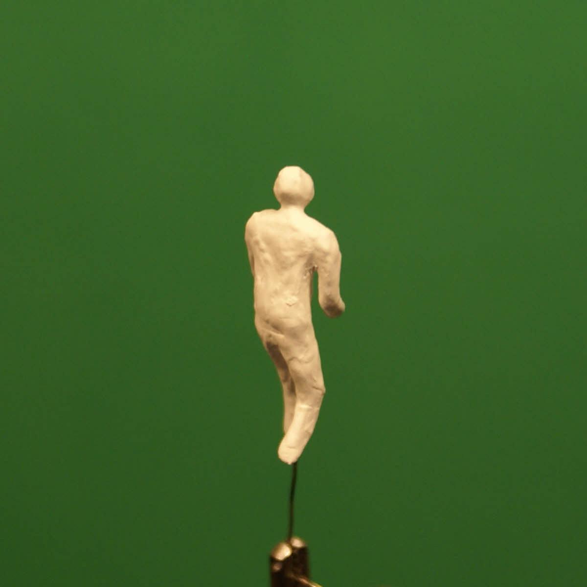
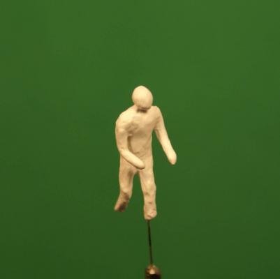
I've been tinkering with the same thing - figures for my ships in bottles. My current project, at 1/96, is unusually large compared to my norm but may work well at more normal ship modeling scales. At this scale my figures will be in the range of .65 in. to .72 in. The technique starts with an armature, but instead of covering it with clay it's built up with acrylic gesso. This artist's material is thicker than Model Expo paints and it dries and builds up quickly applied with a brush, 30 to 45 minutes between coats. Perhaps much less, I applied the coats interspersed with working on other items on my current build. Here's photos of my first try after three coats, it needs one or two more. I chose this process over clay on an armature precisely because I anticipated the problem with Sculpey adhering to an armature as mentioned. From this little bit of experience with the gesso I get the impression that much of the detail can be worked in the gesso during application of the final coat and fine tuned with bits of fine sandpaper. I wrote more about the process on my Ogallala build, last post on page four.


-
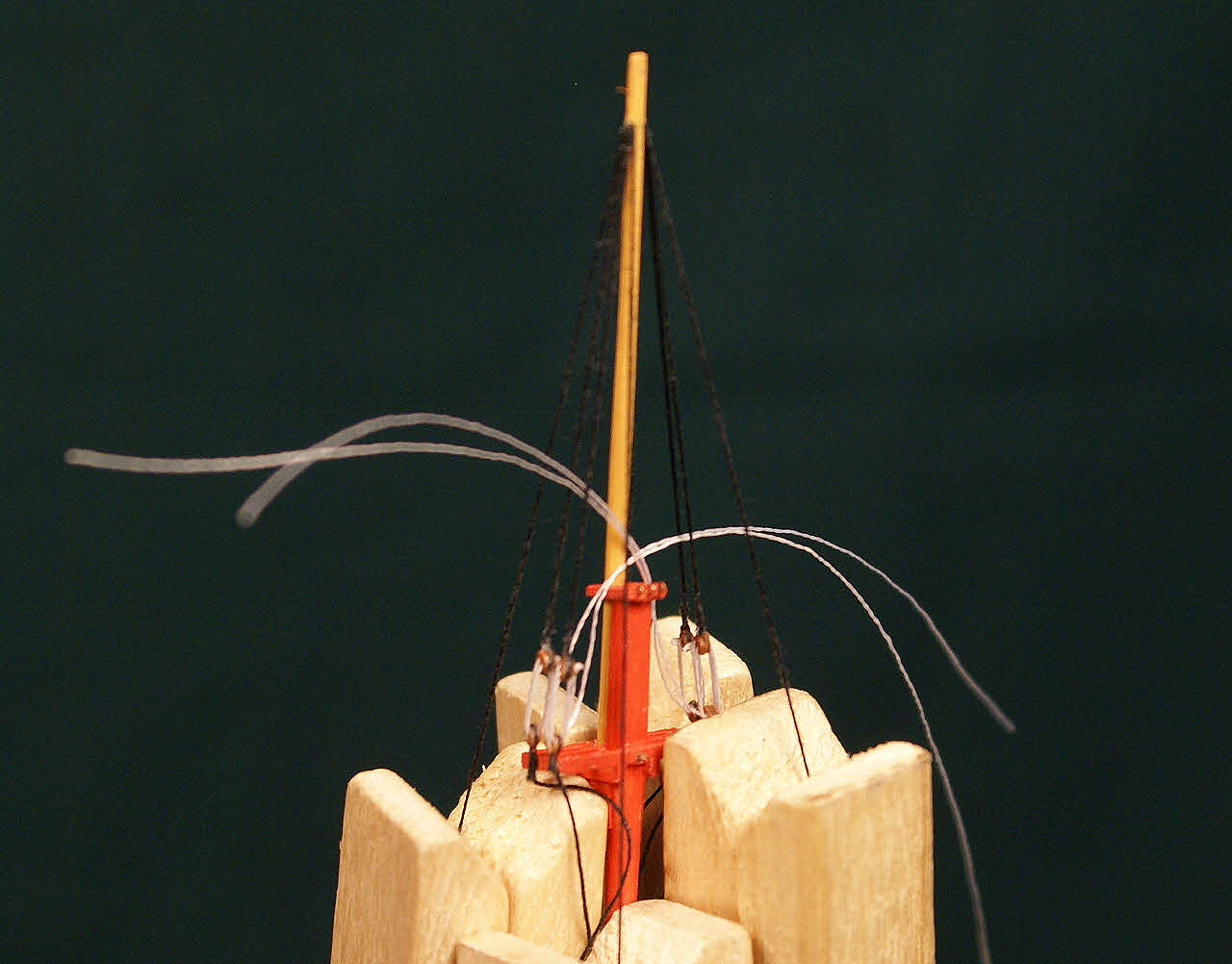
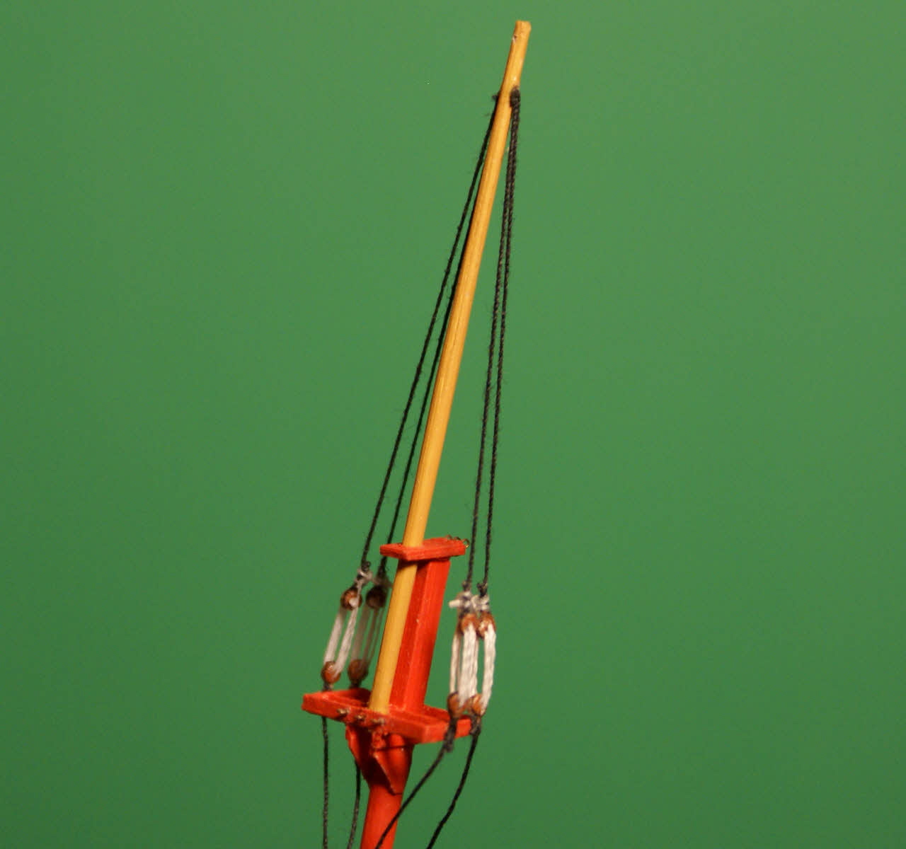
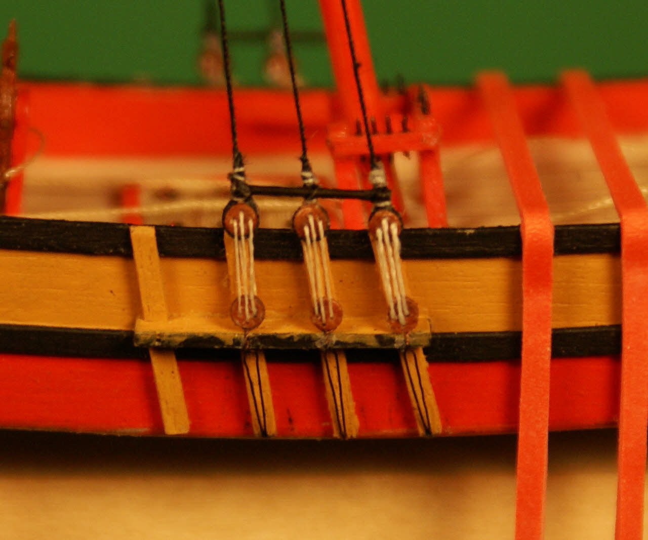
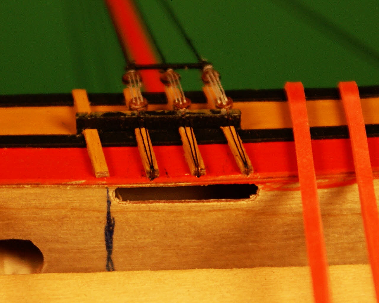
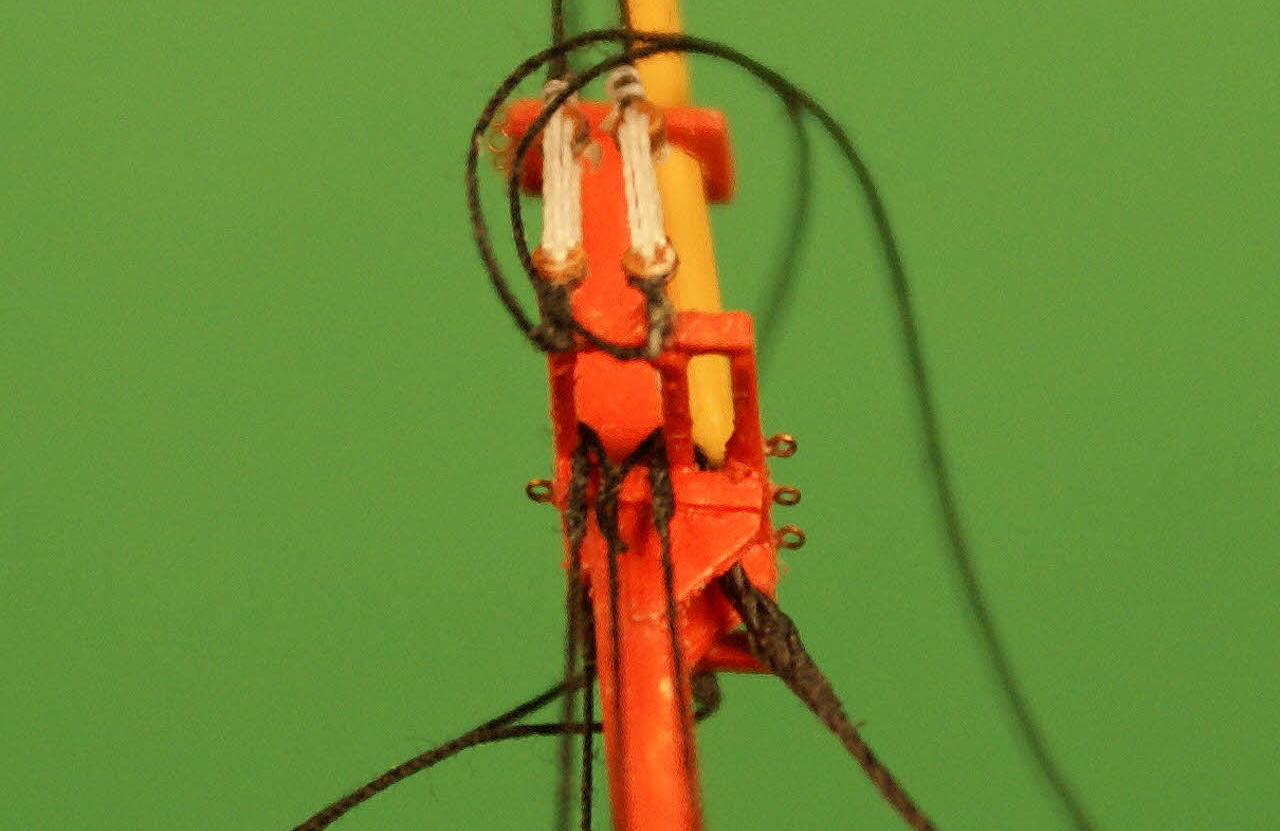
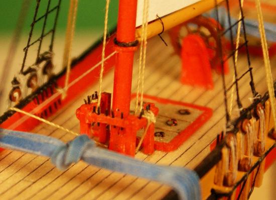
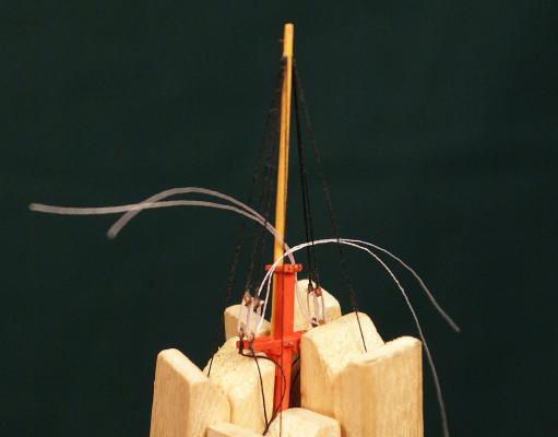
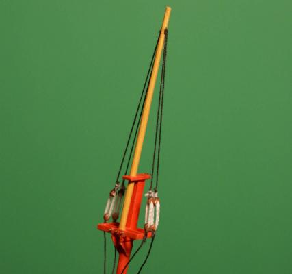
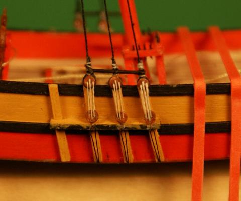
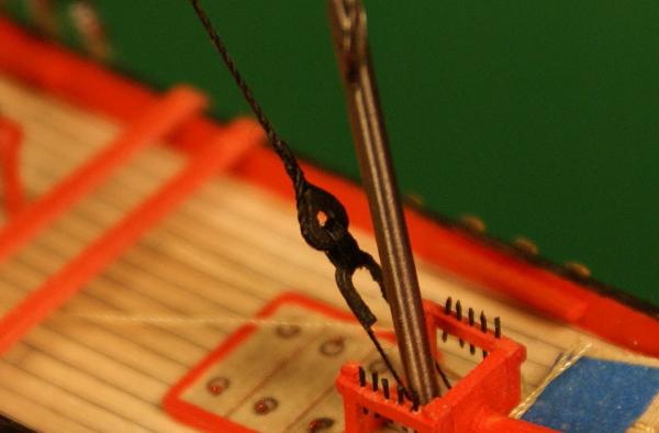
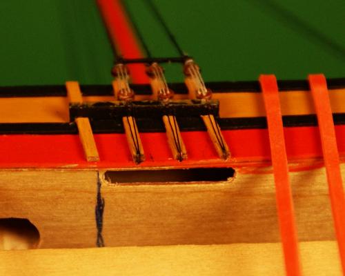
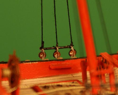
I'm finally getting to my favorite part of a build when all the different mini-projects are installed and I can start tying them all together with rigging - in fact I enjoy doing rigging just on its own. I took the method of making blocks (two discs with a thread sandwiched between then a thread tied around the block) and expanded it to double blocks. This is part of the steering tackle with a double block. I still need to strop it. The white discs are.040 in./1.0 mm in diameter, same as those used to make the double blocks. After I finished making twelve deadeye assemblies with .060 in./1.5 mm deadeyes and eight assemblies with .040 in./1.0 mm deadeyes (plus a couple extras of each) I started rigging the smaller assemblies to the topmasts. Main topmast while rigging the topmast shrouds. After the glue cured on the lower deadeyes at the top, I routed each shroud through the same .020 in./0.5 mm hole in the topmast and tensioned the shrouds with standard size clothespins as shown here. I can't rely on "feel" for equalizing the tension in threads at this size so always use weights, usually clothespins - in this case two on each shroud until the lanyards looked right. I filled the hole in the topmast, which is .035 in./0.89 mm diameter at the hole, with ca. A spar gets seriously weakened at a hole and I avoid holes greater than 25-30% of the spar diameter unless the hole can be filled with ca to restore most of the spar's strength. After the ca cured I trimmed the excess thread flush then tied off the lanyards. I should have tied them off when I made the assemblies - something to remember next time. Completed shrouds at topmast. I'll tie off the futtock shrouds to staves on the lower shrouds later. Before I could step the mainmast I needed to make a heart and collar for the mainstay. I chose to split the mainstay around the foremast simply because putting the mainstay on the starboard side of the foremast messed with my sense of symmetry. After making them I needle spliced an eye around the heart and rigged a lanyard through the heart and around the collar. This stay will be used to erect this mast inside the bottle so I routed the two lower ends through holes drilled in the deck and out the bottom of the upper hull and stepped the mast and rigged a temporary pair of backstays. I needle spliced the upper end of the mainstay making sure that the mast was at the correct rake and the collar near the foremast would not interfere with it. Completed mainstay heart, collar and lanyard. The .063 in./1.6 mm drill bit is standing in for the same diameter foremast. With the mainstay in place I moved ahead with rigging the mainmast shrouds. After gluing the deadeyes to the channels and fixing the chains through holes in the hull I routed the shrouds through the top, attaching each to the opposite side shroud with needle splices. The middle shrouds have one shroud forward of the mast the other aft to form a cut splice around the mast. Not quite accurate to actual practice but pretty close - it's easier to get the mast vertical, side to side, this way than by duplicating the right way. It took a while to get all the tensions balanced out and all the needle splices done, but once I was satisfied that I had the rake correct and the mast was centered I glued the needle splices. After that glue dried (I use pva thinned 50/50 with water on my needle splices) I completed the second pass through of the needle splices, glued them, attached the shroud stretchers and tied off and glued the lanyards. Completed shrouds with chains, stretcher and tied off lanyards. I still need to rig a breast backstay and touch up the paint on the edge of the channel. Inboard view of deadeyes, stretcher and tied off lanyards. Before I could do any of this work I had to cut holes in the bottom of the upper hull to get access behind the holes for the chains. Another angle of the chains showing the access hole where the chains were fed through a hole, bent to the sides and glued. While the schooner was on its side I got a shot of the underside of the top to show needle splices of the shrouds and the eye splice on the mainstay. I found that the blackening on the chains flaked off from handling and bending (which left black smudges on the hull I need to touch up) and tried a permanent black marker on them which worked very well. I tried the marker earlier but it wouldn't take so must assume that the acid in the blackening product etched the copper enough for the ink from the marker to adhere. A bath in acetic acid (vinegar) will probably work just as well. Sorry, I forgot to include visual size references in the photos. Next, the foremast rigging and finishing the incomplete work on the main. Dave

- 170 replies
-
- 11
-
-
- ogallala
- praire schooner
- (and 2 more)
-
Thanks Bob and Jeff. Got all 20 of the deadeye assemblies made and starting rigging them to the tops and topmasts. Also got more detailing done on the fore crossjack and topsail yard and some preliminary work on the upper hull for rigging. Photos and descriptions in a couple days when I'm a little further along. Dave
-
Thanks, Michael - I think. And thank you, Mark. The hard part of getting that photo was photo-shopping the 3X scale X-acto blade. Michael, you reminded me of a story I heard when I was in college. A couple of grad students working in the materials technology lab made what they thought was the smallest drill bit in existence and sent it to one of the foremost Swiss watch makers - no message, just the bit. It came back, also with no message - just the bit with a hole drilled through the shank. Dave
-
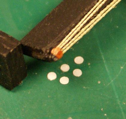
Here's the first pair of .040 in./1.0 mm deadeyes with lanyard, posed with a bigger pair (.060 in./1.5 mm) from a few days ago. Left, 1.5 mm deadeye assembly; right, 1.0 mm deadeyes. Dave


- 170 replies
-
- 7
-
-
- ogallala
- praire schooner
- (and 2 more)