molasses
-
Posts
455 -
Joined
-
Last visited
Content Type
Profiles
Forums
Gallery
Events
Everything posted by molasses
-
 Jeff: I have lots of proportion diagrams that show where the joints are, range of motion, etc. with the most useful to me printed out for reference including one set reduced to the size of my figures. I haven't worked on him today - I'm rigging dead eye pairs, maybe later. Dave
 -
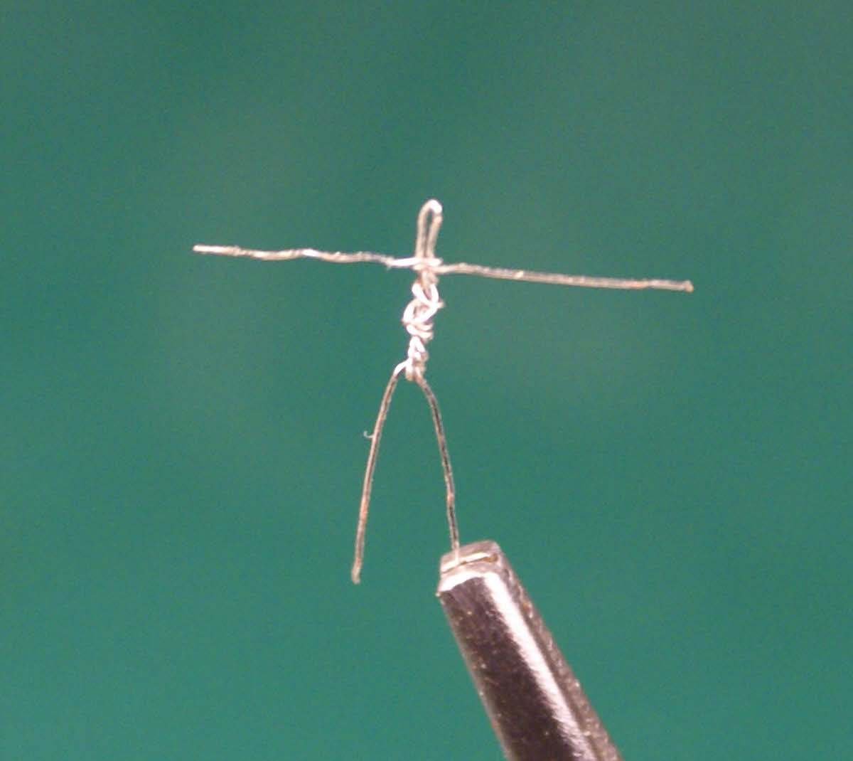
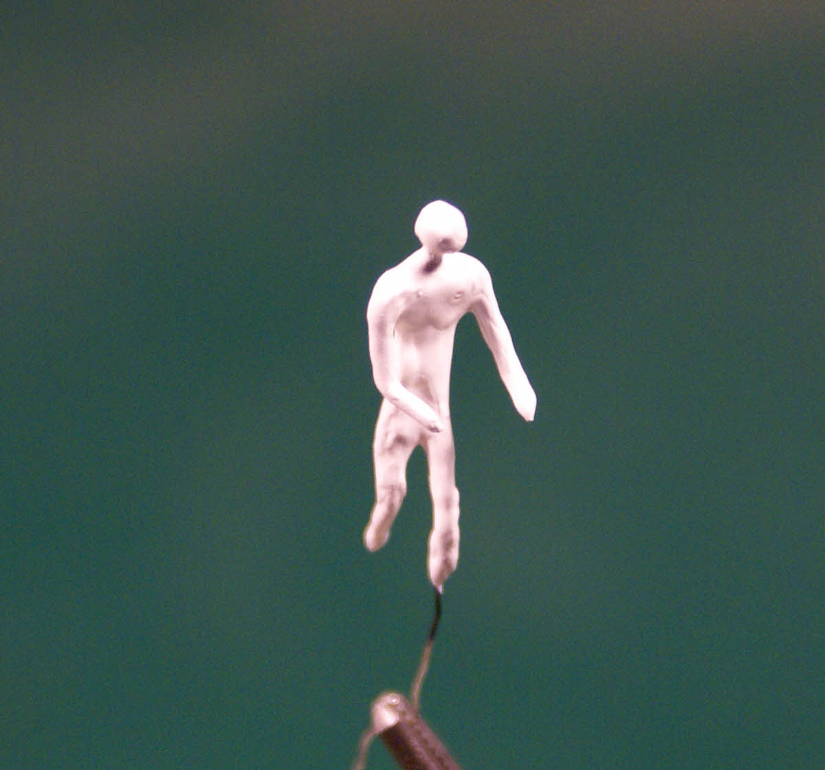
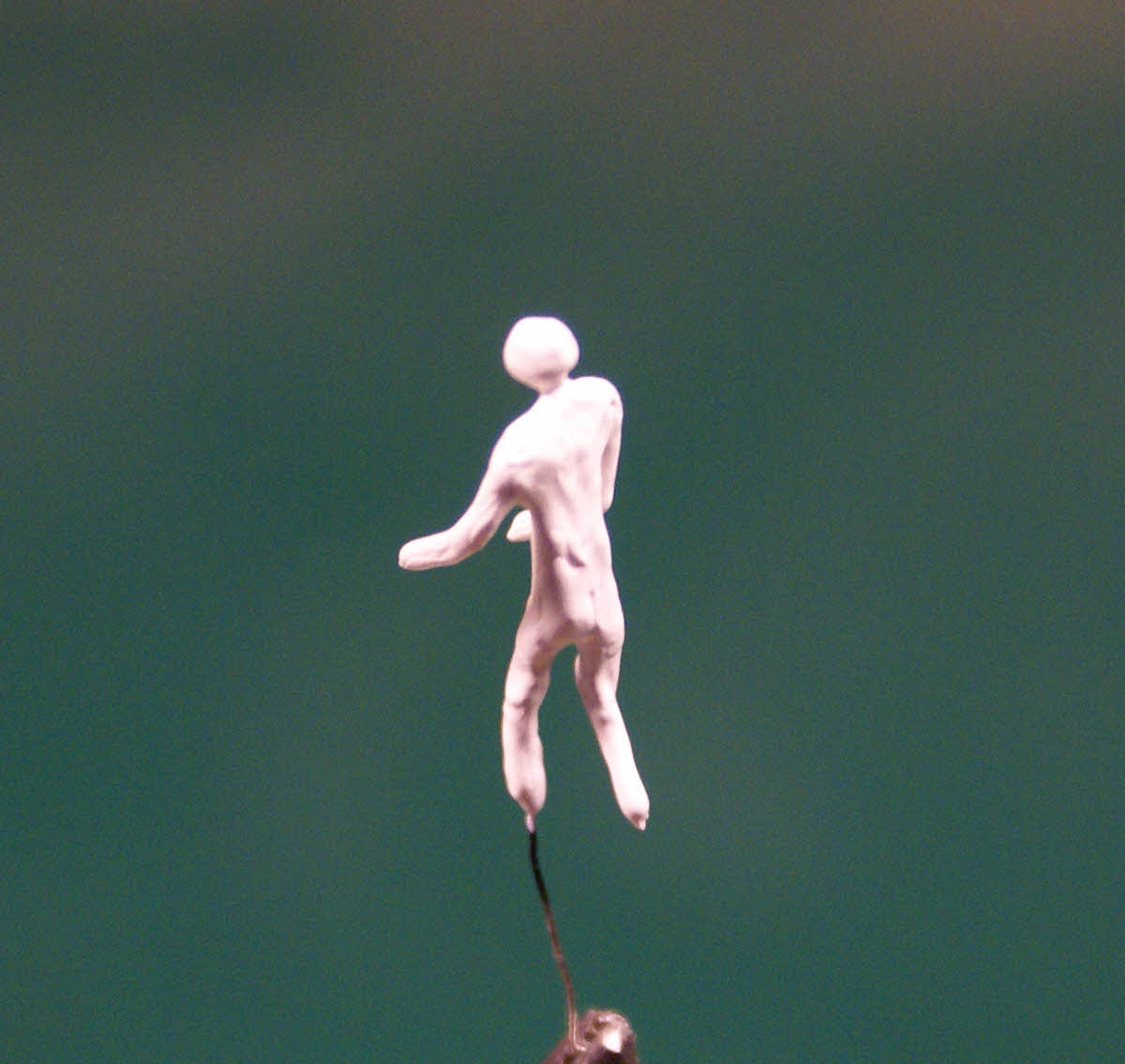
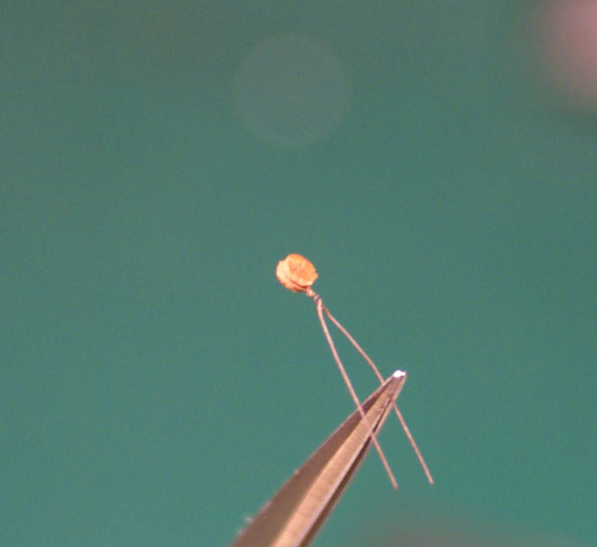
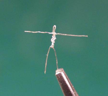
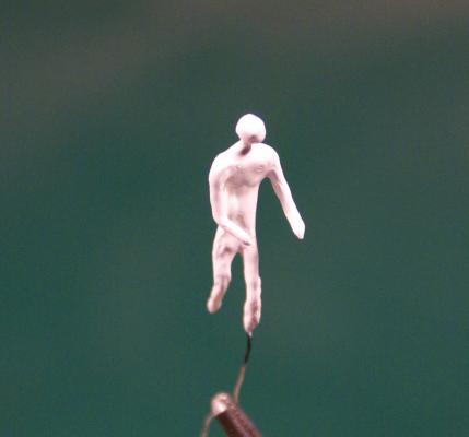
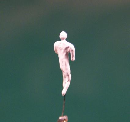
I've been building ships in bottles for more than 35 years and every one of them has been a waterline model, most under full sail, with the wind direction and strength appropriate for the sails and correctly depicted (more or less, as my experience and knowledge grew) in the sea state and swell direction. However, there was always something that bothered me about my models, increasing as time went by, because I had no confidence that I could succeed in modeling something that everyone is extremely familiar with. I have finally gotten to the point where I can no longer leave out these details. In case you haven't guessed, I'm talking about putting people on my models. There's nothing like human figures to give a strong sense of the scale of a model and bring it to life - or ruin the project if they are poorly done. I'm no artist, just a modeler, and I was always lousy at drawing people. Just the thought of sculpting human figures had me extremely intimidated so a couple months ago I started research and study of the human body from an artist's point of view and on ways to make very small figures. Ogallala seemed to me a perfect project to introduce people into my work since it is a rather large scale and has become an experimental test bed. It's basically a 2X scale Conestaga wagon mated to a 1/2 scale topsail schooner rig, then reduced to a scale appropriate to the bottle I initially selected. The result is roughly 1/96 scale, about 10% smaller than HO. I rejected using HO figures (which would be large anyway) because I couldn't learn anything by buying figures and adapting them. Most methods I researched begin with wire armatures, so that's were I started. My first armature with the arms not yet bent at the shoulder joint and arms and legs not trimmed to length. I dropped - and thought had lost - that first armature, made a couple more, threw them away and finally got one that might work as a first try. I rejected using any kind of clay and settled on building up the armature with an acrylic gesso, mostly because Lloyd McCaffery uses gesso. [bTW, I found that first armature today while doing a bit of work area clean-up and photographed it. I'm convinced that a smooth, bare concrete floor is the best thing under a modeler's work bench/table, I hardly ever lose dropped objects on that floor except for the semi-microscopic bits I don't even bother to look for.] So, here's my first try after three coats, applied at about 30-45 minute intervals, between drilling holes in groups of dead-eyes. Front view. He's posed for steering, weight on left foot, left hip against the wheel stanchion, both hands on the wheel. Left quarter view. I think I have the head and shoulders pretty close but he's still a bit thin elsewhere. The long left leg will be cut below the foot to glue into a hole in the deck. Right quarter view. He's 5'-9"/1.75m tall to scale - 11/16 in./17.5mm. One or two more coats of gesso should have him ready for detailing. I'm very surprised at how easy this method is, at least this far into it. If I was doing a larger crew, say 20 figures, at this scale (I'm only going to do three or four for Ogallala), I would be able to apply a coat of gesso to all, go back through them with successive coats and have them all ready for final detailing in one day, perhaps four hours or much less with practice or for a smaller scale. Making the 20 armatures and posing them in a wide variety of activities would take longer. The gesso, being a little thicker than Model Expo paint, builds up easily with a paint brush and sets quickly. Used as a base for painting, it's a brilliant white, so it's a bit difficult to see the shape of the growing figure - and very hard to photograph; my first photos were just white silhouettes with no shadows to give a discernible 3rd dimension. I'll add a bit of black paint to the gesso for the final coat to make it easier to see as I finalize the fleshing out and the drape of the clothing. I'll continue working on this figure to learn about the rest of the process before starting the two or three more needed. Don't be surprised if he winds up being a less cartoonish version of Windwagon Smith. Looking back on my agonizing over doing people, I feel really stupid (a frequent feeling) and timid (very rare) for not trying this 20 years ago - it's not at all like drawing, it's really just modeling after all. I guess it took Lloyd McCaffery's work to make me see that I might be able to do it combined with the realization that I had no choice but to at least attempt it. As you can probably tell, I'm very pleased with what I have so far. He's off to a much better beginning than I expected and my confidence now is high, which is probably the most important result of this experiment. I will greatly appreciate any comments, positive and negative. I need to learn quickly how to do these figures, and other eyes - and the intellects that go with them - may notice what I have missed. Dave


- 170 replies
-
- 11
-

-
- ogallala
- praire schooner
- (and 2 more)
-
Thanks for the kind words, everyone. You're welcome to sit in, Crackers - and you can take a front row seat if you share. While looking over my photos I noticed that the group of holes in the dead eyes were a bit off center (by about .004 in./0.1mm) and corrected the drilling fixture.
-
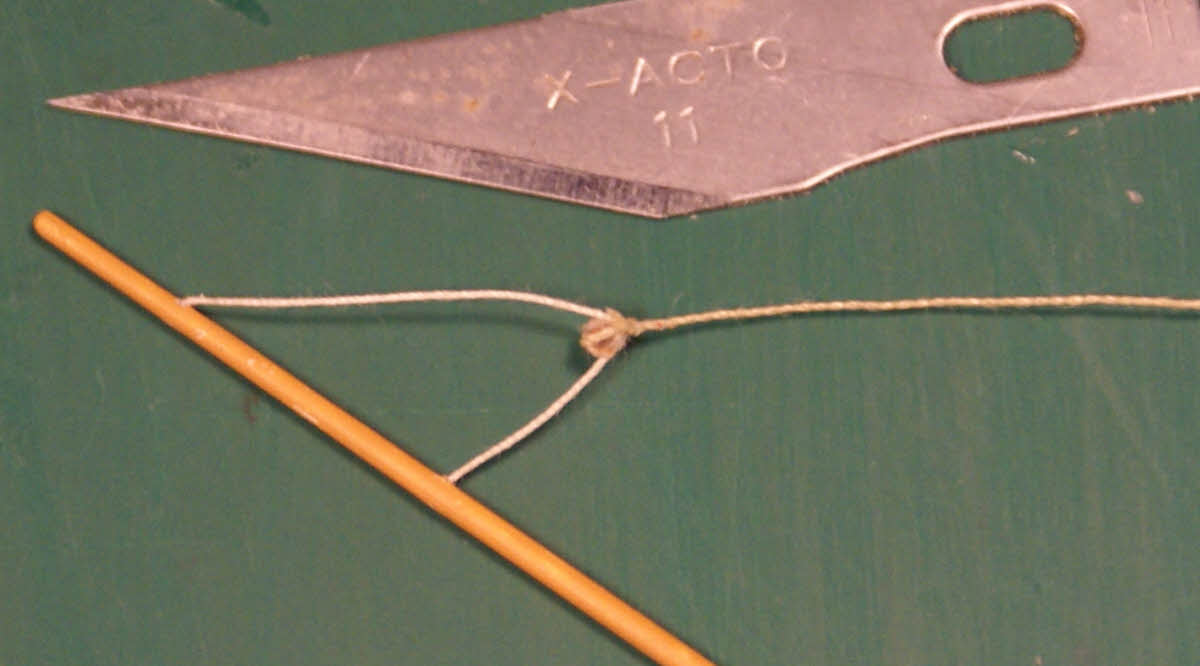
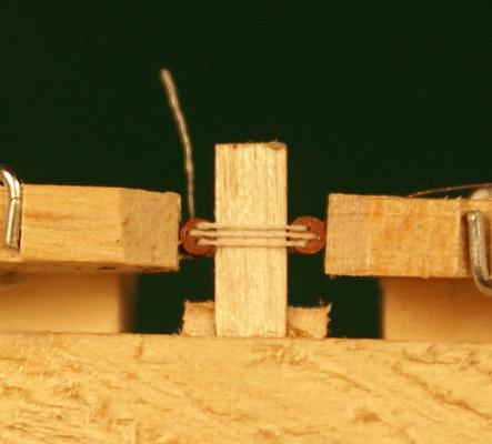
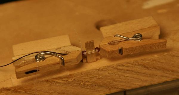
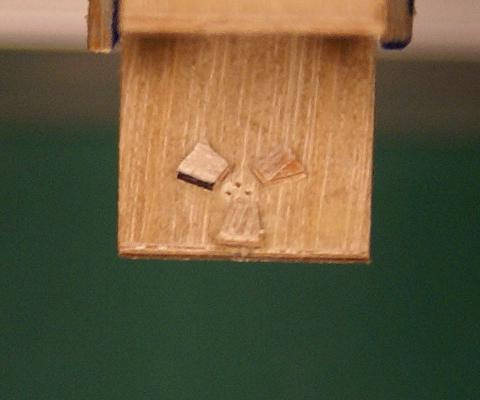
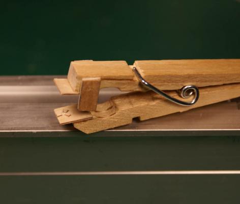
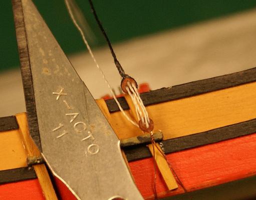
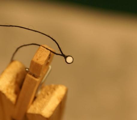
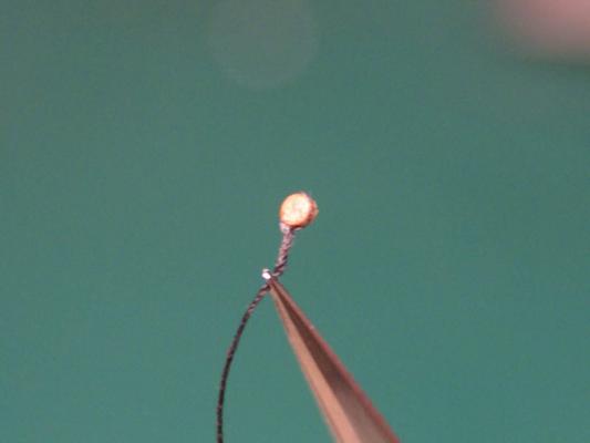
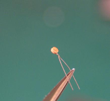
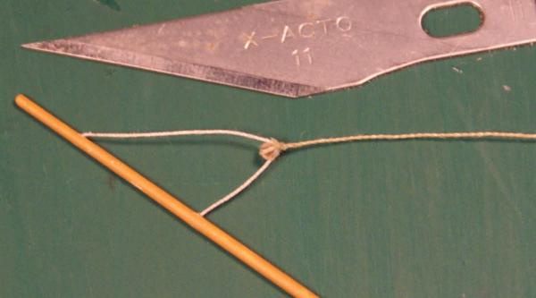
I decided to drill holes in the dead eyes and to rig lanyards rather than to fake them by gluing segments of thread to both faces of the dead eyes. I don't fully trust ca (used to make the dead eyes) and paint, in particular, to withstand rigging stresses. By rigging them, even if the ca fails, the dead eyes are less likely to come apart with the lanyards to assist in holding them together. By faking the lanyards I would be trusting the paint-to-deadeye bond to not fail. In either case repairing failure(s) would be next to impossible inside the sphere. I realized I had no choice but to rig them for real. I started by fabricating a fixture using a standard spring clothespin as a clamp to hold the dead eye for drilling through guides in the clamp. I used 1mm hobby plywood to make the parts added to the clothespin. The guide holes are .010 in./0.25mm. The pieces on both sides of the clothespin keep the two wooden parts of the pin from shifting sideways. Three bits of ply glued to one of the ply yaws to locate the dead eye and the three guide holes for drilling. I also made a fixture to hold an upper and lower dead eye for reeving with a lanyard. I modified two mini clothespins to hold the dead eyes by the previously installed tails with a piece of the ply positioned between to sort of wedge the dead eyes against the clamps. Dead eye reeving fixture, lower dead eye to the right. Closer view of the fixture. The out-of-focus light thread is the tail from the knotted end of the lanyard. I used some thinned white pva glue to secure the lanyard in the holes and on the knot. I will secure the other end of the lanyard after rigging the shrouds and attaching a stretcher just above the dead eyes. I know this all seems backwards to the method used on larger models but tying and seizing and reeving the lanyards on the model at this size seems to me next to impossible. It was hard enough with the parts held steady in clamps and fixtures. This way the only tying while on the model will be of the shrouds at the tops to form short splices or bight splices with a needle similar to the way I seized the dead eyes. After letting the glue set I removed the shroud from the fixture and posed it in position in a channel on the model with an X-acto blade for size reference. The lanyard is not tensioned at all. It has acquired a bit of a twist which comes out with a little tension. I have to be careful when I reeve the lanyard so that the lay doesn't tighten as I pass it through each hole of the dead eye. Now to get back to the other eleven pairs of dead eyes to drill holes and reeve lanyards, then go through the whole process again, starting with cutting discs, for the smaller topmast dead eyes and shrouds. Dave

- 170 replies
-
- 14
-
-
- ogallala
- praire schooner
- (and 2 more)
-
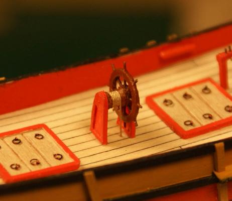
I've been working on some very fiddly bits the last few days so it doesn't seem to me that I have much done when I look back on the time I spent at the bench. I made a test assembly of my dead eyes. The dead eyes were fabricated from two discs .060 in./1.5mm in diameter of ca stiffened card stock with another disc .040 in./1.0mm sandwiched between and centered. In this test I seized the thread around the dead eye by passing the thread through itself twice with a needle. If you think threading a needle is challenging try piercing a thread with a needle. Satisfied with the general results I punched out the discs needed to make 24 dead eyes with plenty of extras to cover mistakes. I also made my ship's wheel from the ca stiffened card stock. Made 3 rings, glued two together then cut notches for the 36 gauge wire to fit into. Did similar with the hub of the wheel, then assembled the wheel and glued another ring and hub in place. I also used the card stock to build up the wheel stanchions. I turned the spindle from basswood. Here's the wheel after going into the paint shop, attaching the tiller rope and installing the completed unit to Ogallala's deck with the tiller ropes passing through holes in the deck. While working on the wheel I also assembled the dead eyes and painted them. Here's one of the dead eyes with a shroud seized as in the test. This dead eye has blackened 36 gauge wire wrapped around it and twisted just enough turns to conceal the twist when attached to the channels. I may need to blacken the wire some more, it looks black in normal light but with the lights for photography the copper shows through. If I blacken the wire too much it just flakes off. I haven't decided if I'm going to drill holes for the lanyards or just fake them by gluing short pieces of thread to both sides of the dead eye pairs. Now to make smaller dead eyes for the topmasts. Dave

- 170 replies
-
- 10
-
-
- ogallala
- praire schooner
- (and 2 more)
-
Suggest you check other pages because there are missing pics on pages 16 through 19.
-
I found this photo with the caption: "PMARIG working on the Coronation site in 1999 (SHIPS Project)" which could lead one to assume that PMARIG was the name of the ship. However, PMARIG stands for Plymouth Maritime ARchaeological Interest Group which is comprised of dedicated amateurs interested in maritime archaeology in the Plymouth area since 1995. This group pioneered many techniques since adopted by professional archaeologists and offers training in underwater archaeology. I did identify the small boat, Nova T, used by the Malvern Archaeological Diving Unit, participants in the 1999 Coronation wreck site survey. I don't think that counts for the win.
-
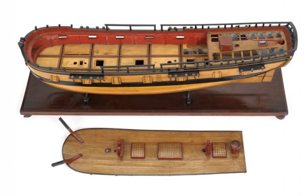
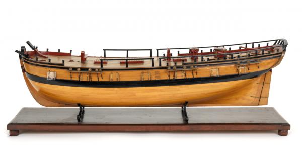
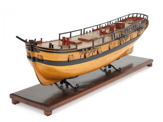
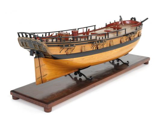
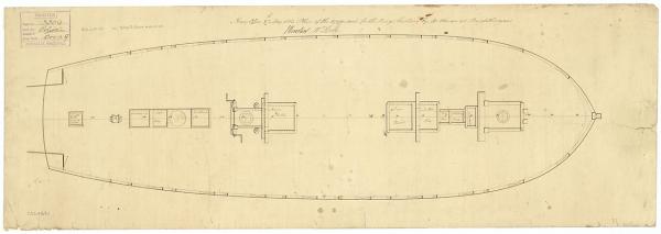
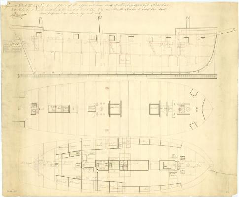
Very good, Jason. I held back a fourth photo that shows the grooves in the deck. Armed on the lower deck with 2 x 18 pound cannon and 6 x 24 pound carronades that were secured on the centerline of the brig when not in use then shifted to the engaged side during battle. This clearly could present a big problem when engaging from the lee side because the heeling of the brig from the wind plus all that weight well off center could easily leave the gun ports under water. She also had 2 x 12 pound cannon forward and 4 more aft on the weather deck. This armament gave her a weight of broadside about equal to that of a 32 gun 12 pounder frigate in a vessel about half the size and requiring one-third the crew. Commissioned in 1798, Wolverine engaged a French 30 gun privateer frigate to protect her convoy in 1804. After an hour of battle she was forced to surrender and sank 15 minutes later. Your turn, Jason.
-
Thanks, Jason. To continue with the trend here's another contemporary model. Please note that this sloop model is ship-rigged even though the sources I've consulted say this sloop was a brig. This model was built to illustrate the experimental features of this sloop and I suspect that the rigging changes were not made to the brig purchased for the experiment. Good luck! Dave (not Doug )
-
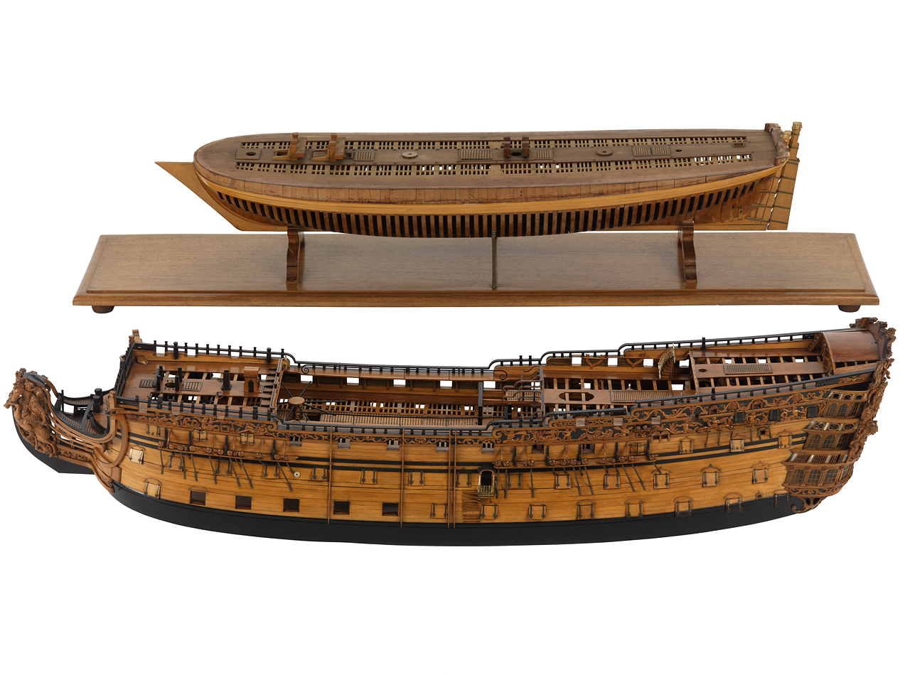
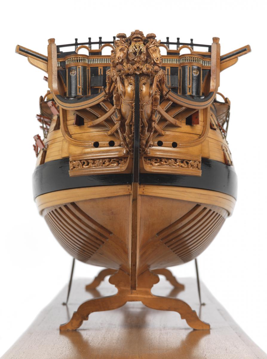
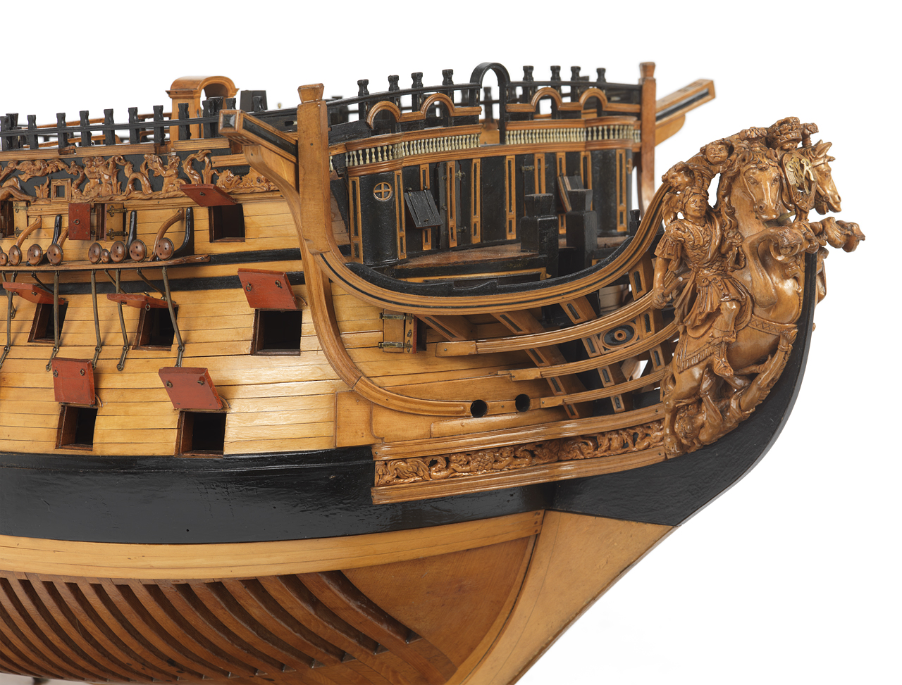
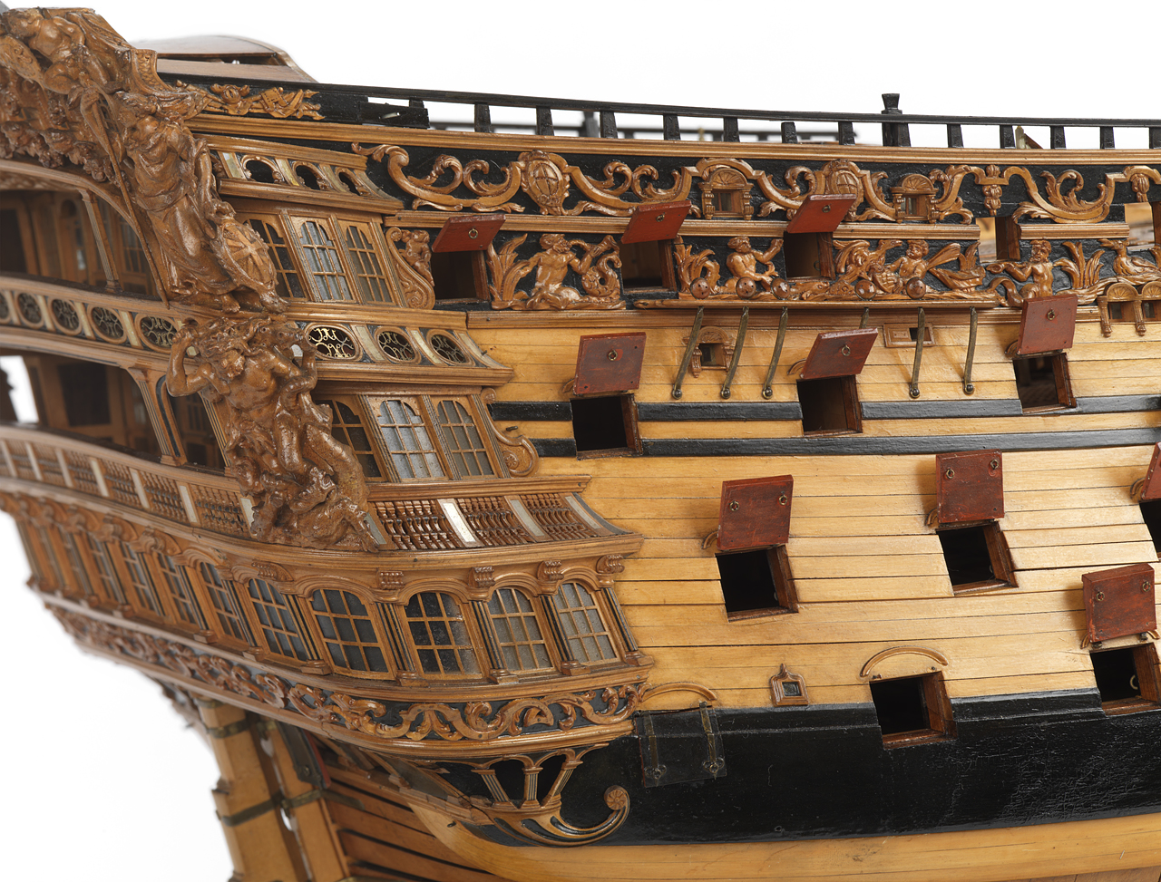
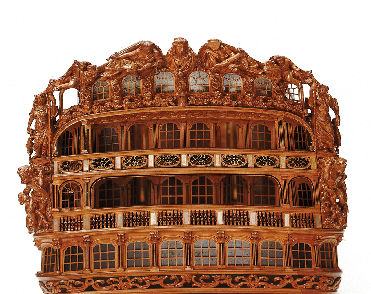
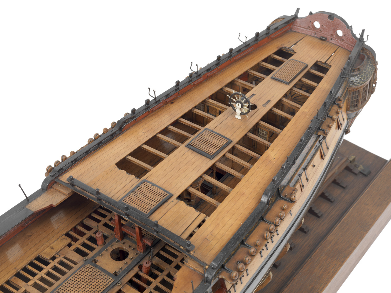
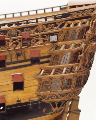
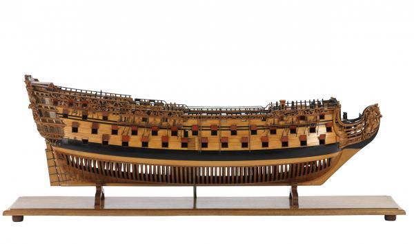
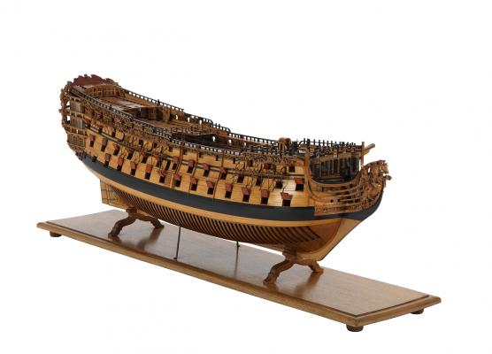
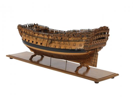
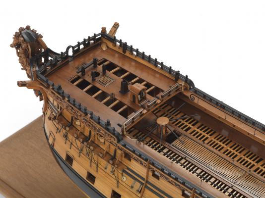
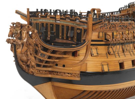
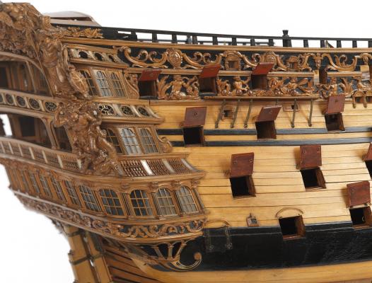
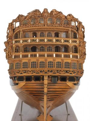
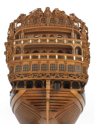
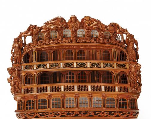
This model is of the 100 gun first rate Royal William for the 1714-19 rebuild. Originally the 100 gun Prince of 1670, she was rebuilt, enlarged and renamed Royal William in 1692. She was enlarged again for the 1719 rebuild. Royal William had her armament reduced to 84 guns in 1756 and was scrapped in 1813. This is a spectacular model and remarkably well preserved for being 300 years old! It is not on display at the NMM, Greenwich. I've posted the entire gallery of photos of this model. For best viewing click on an image (the photos shown on the page are just thumbnails), use the "prev" and "next" tabs near the upper corners (or keys "p" and "n") to scroll through the photos - and be ready to pick your jaw up from the floor. Thank you, Jason, for bringing this stunning model to our attention. Dave


-
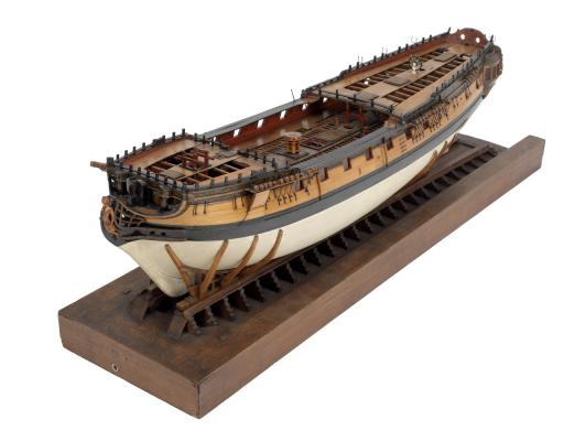
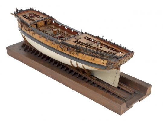
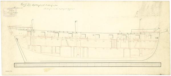
Richmond class is correct. The model is not identified as to which specific ship, "possibly Thames" is how it's labeled. I thought this model, which is not on display at the National Maritime Museum in Greenwich, was worth being seen. I came across it while reading about Admiral Edward Pellew, 1st Viscount Exmouth. His first ship as a 14 year midshipman was the Richmond class Juno in 1770. After serving as temporary captain of the Artois, his first permanent post command was the Winchelsea from 1786 to 1789 out of Newfoundland. Your turn, Jason.
-
I figured Niger/Winchelsea would be a first guess because of our familiarity with it and the close resemblance. Close, but no cookie.
-
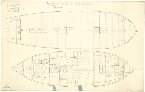
Here's four views of a model contemporary to the ship. Naming the class will be close enough. Name the ship: Good luck! I found another photo of this model.


-
The pre-dreadnought battleship, Evstafi (Евстафий), and her sister ship Ioann Zlatoust (Иоанн Златоуст) were named for Saint Eustace and Saint John Chrysostom ("golden mouth" in Greek), respectively. They were larger versions of the better known Potemkin with increased armor and more guns. Launched in 1906, their entry into the Imperial Russian Navy's Black Sea Fleet was delayed until 1911 for improvements dictated by the Russian experience in their war against Japan. They were captured by the Germans in Sevastopol in 1918 and turned over to the Allies after the Armistice. The British destroyed their engines in 1919 before the White Russians abandoned the Crimea in 1920. They were scrapped in 1922-23.
-
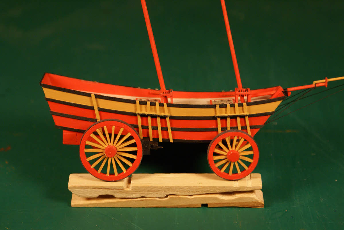
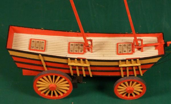
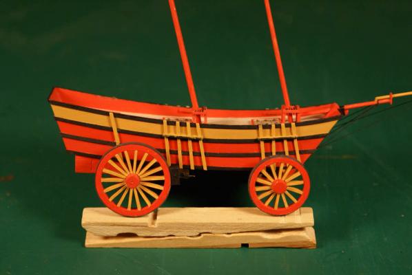
I get a lot of comments on the colors. The historical builder was a ship's carpenter turned wagon wright who had some cheap barn red, yellow ocher and black in his paint shed but not enough of any one of them to do the whole job. Truth is I thought the color scheme looked good in my first drawing and accented the details well so I kept it just for fun.
- 170 replies
-
- 1
-
-
- ogallala
- praire schooner
- (and 2 more)
-
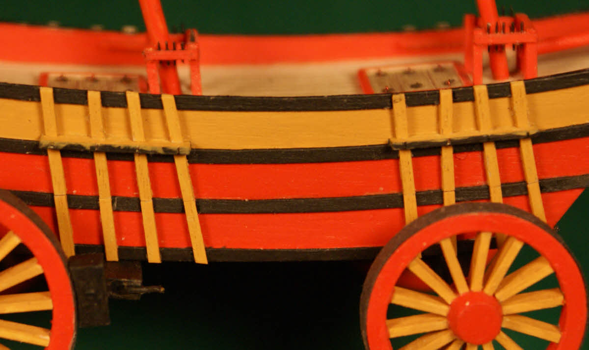
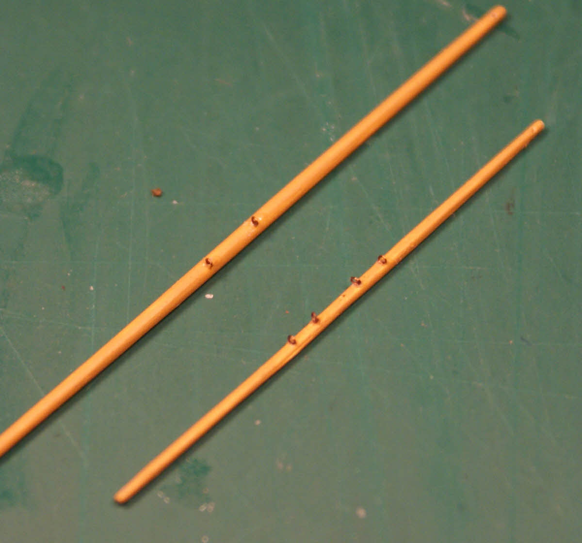
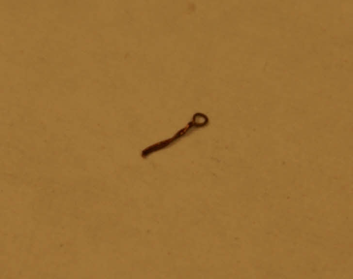
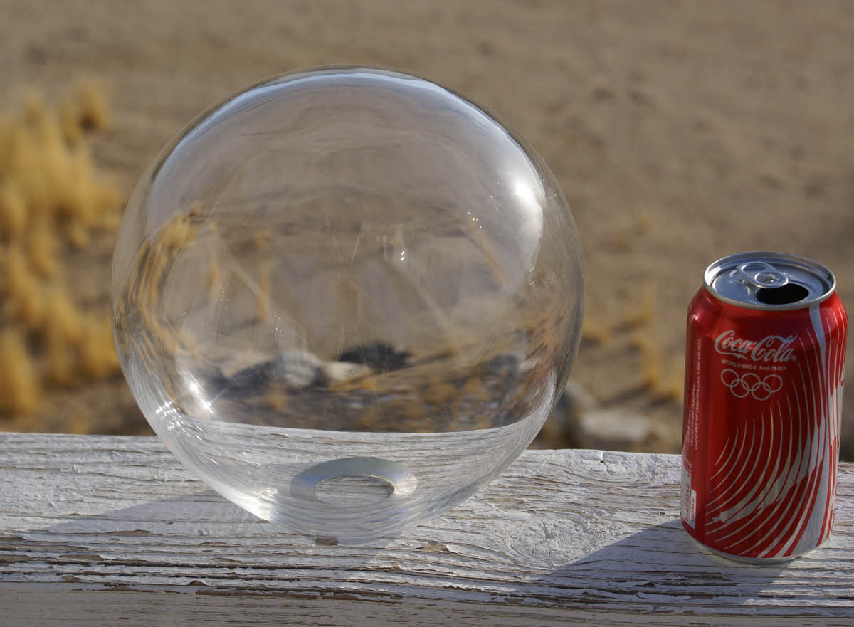
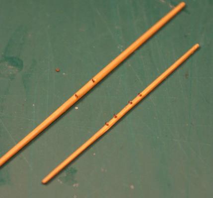
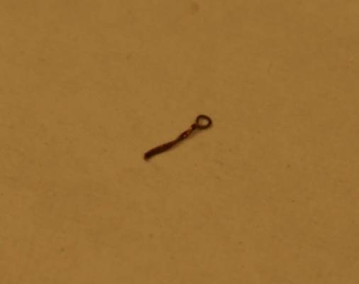
Finally making some progress on this project. I have seen SiBs built in light bulbs, clear glass Christmas ornaments and vertical bottles and liked the ability to view the model inside with minimal distortion from almost any angle and decided on an 8 inch (200mm) diameter sphere with a hole about 1 3/8 inch (35mm). My custom "bottle" A characteristic of Conastoga wagons, on which Ogallala's hull is based, is the external ribs. During the design phase I chose to have most of these external ribs do double duty as attachments for shrouds and backstays. Channels and external ribs in place. I also installed pinrails on the inboard side of the bulwarks but they don't show up well because they are red and don't have the belaying pins inserted. The tedious part of doing the ribs was achieving an "invisible" butt fit at the line where the hull separates into two parts. Another view. Can you see the dividing line? The ribs look kind of irregular because they are aligned to the corresponding points on the masts for the shrouds and backstays. I'll touch up the black on the edges of the channels after installing the deadeyes. Close up of ribs. You might be able to see the dividing line if you click on this for the full size image. I have tried different methods of simulating blocks at SiB scales - thread knotted and glued around the point of a needle (thread blocks) and using small seed beads - without being satisfied with the results. Neither of these look much like a block. So I came up with using two discs cut from ca-stiffened card stock to sandwich the line passing through the block then tying the end of a line around the sandwich and gluing it. Here's the result after some experimentation. This block is .040 inch (1mm) in diameter on one of the gaff bridles with halliard attached. Of course, double and triple blocks can be made by adding threads and discs to the stack. I have all my spars made but still have some detailing to do to them. Here are the fore crossjack with two micro eye bolts installed and the fore topsail yard with four installed. They also have .010 inch (0.30mm) dia. holes drilled in them very near the tips. The topsail yard is 1.650 inches (42mm) long, .037 inch (0.94mm) dia. at the center and .027 inch (0.68mm) at the tips. This is about my limit for a spar with a usable hole, I have not (yet) been able to feed a thread through a smaller hole. Fore crossjack and topsail yard. Here's a close-up of an eyebolt made from .005 inch (0.13mm) copper wire made by bending the wire around a .010 inch (0.25mm) hard wire then twisting the ends until the eye is snug. I also installed four of these in various places in the foretop and seven in the maintop and still have several to install on the deck. Most of these eyebolts will be covered with disc blocks during rigging after feeding thread through the eye. I'm glad to be back at work on Ogallala after my set-back as a result of miscalculating the overall width of her hull. Stupid me. Dave


- 170 replies
-
- 8
-
-
- ogallala
- praire schooner
- (and 2 more)
-
Cruizer-class Brig-Sloops of the Royal Navy
molasses replied to molasses's topic in Nautical/Naval History
Joe: Of those you mention I cannot confirm that any of them had the aft platform. The forward platform is mentioned in the accounts of the actions for Frolic, Peacock, Epervier, Reindeer and Penguin. I had made an assumption that the brigs with a forward platform also had the aft platform but am coming to realize that may not be true. Of course, Epervier could be modeled as either Royal Navy or US Navy. In the US Navy Epervier was armed with 18 x 32 pounder carronades. Her appearance in the US Navy is documented in Howard I Chapelle's The History of the American Sailing Navy. Please review the armaments as listed in the individual articles, they varied widely, e.g. Peacock and Reindeer were armed with 16 x 24 pounder carronades instead of the 32s and Epervier when captured had 2 x 18 pounder boat guns instead of the 6 pounder cannons. Good luck -
Cruizer-class Brig-Sloops of the Royal Navy
molasses replied to molasses's topic in Nautical/Naval History
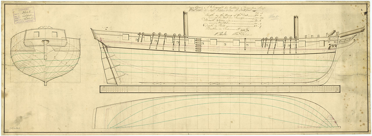
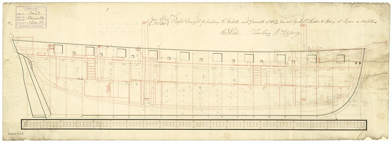
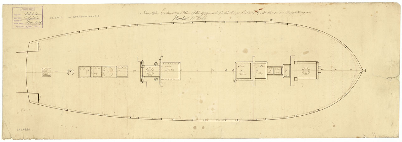
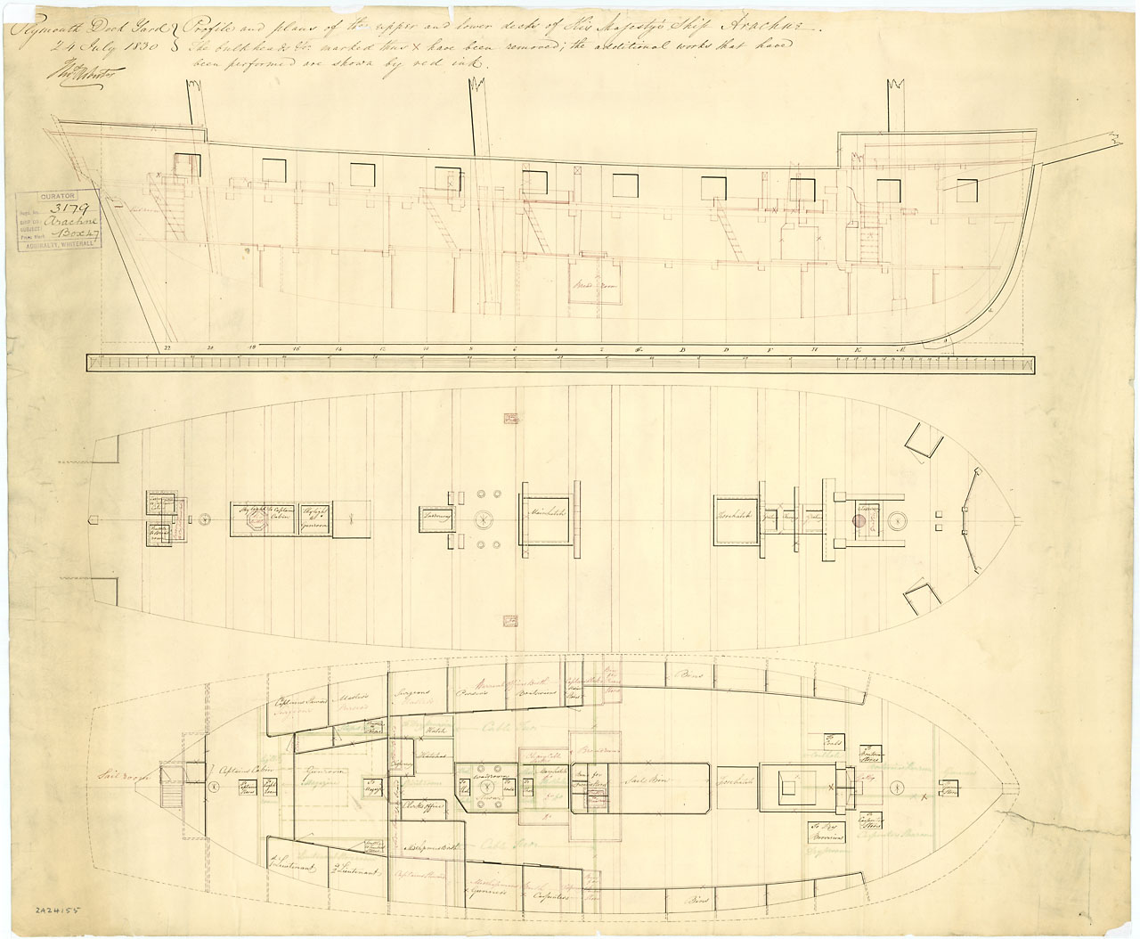
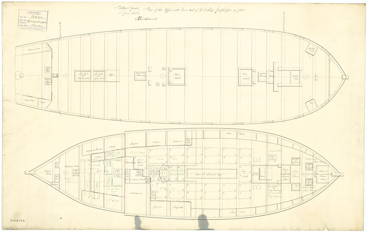
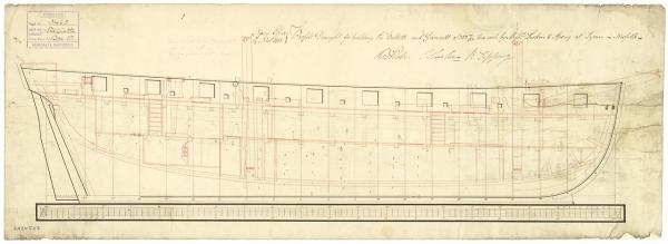
Joe: there are several ways to go to build something a little different presented here in no particular order except for the kit that I think presents the least scratch building. All ships mentioned have plans at NMM. 1) Cruizer kit. As near as I can tell, without doing a lot of digging, is that 50 to 70 or more Cruizers were built with the fore and aft platforms, and that guess is based on the plans that list the brigs built from those plans, but it doesn't guarantee that those individual brigs were built with platforms. This route would require upgrading 16 cannons with 16 x 32 pound carronades. I've been following most of the Snake builds (no Cruizers right now) and all those builders were unhappy with the carronades in the kit and bought the upgrades from Caldercraft which would be expensive. Chuck (w/Syren) has been promising carronades but he doesn't list them yet (at the time I'm writing this) and his carronades may be cheaper and of even better quality. Alert (1813) 2) Cruizer kit. Some of the plans at NMM show a few of the later-built brigs without the platforms (Alert of 1813 for one). Others show them with a pair of small enclosed heads on deck at the aft corners (Redwing, Eclair, Sparrowhawk in about 1806). Redwing (1806), Eclair, Sparrowhawk 3) Cruizer kit. Bellette and Gannett, both built in 1814, had the aft two heads, like in 2), but with a larger forward platform that covered the chase ports and 6 pounders. This platform almost butted to the fore mast and was set higher than the usual platform to give working room under it, but not much. Bellette and Gannett (1814) 4) Snake kit. Beginning in about 1822 many of the remaining Cruizers were refit as ship-sloops (Fly 2, Grasshopper 2, Arachne, Thracian). The forward platform was enlarged around the fore mast and raised with a bulwark and the aft platform extended almost to the mizzen and raised so the helmsmen were under cover. This platform was not intended as a deck, just a cover, and is without ladders. The two aft enclosed heads were under this cover as were two more enclosed heads under the forward platform. The transom also appears to have been reset to a bit more vertical position. The tiller may have been raised to above this platform and rigged to eliminate the tiller rigging under the cover. Mast locations appear to be slightly different on many of these refits Fly and Grasshopper of 1813, both were the second Cruizer class brig with the name. 5) Snake kit. In 1830 Arachne was again refit with a different foremast location and change in the size of the bulwarks on the forward platform. Arachne as refit in 1830 showing the earlier refit in about 1823. I don't know if any of this helps you or just adds to the confusion, but it's something I wanted to point out as options for building something different.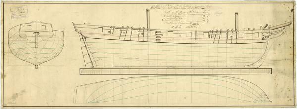
-
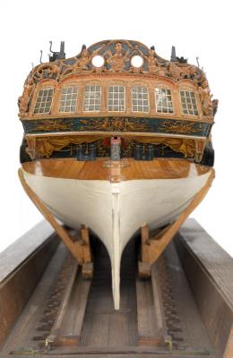
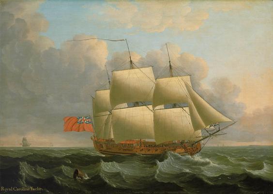
Jeff: Here's a very nice contemporary portrait of HMY Royal Caroline by John Cleveley the Elder that might be useful. She was renamed Royal Charlotte in 1761 when sent to convey Duchess Charlotte of Mecklenburg-Strelitz to England to marry George III. I would be intimidated by the ornate decoration. She will make a lovely SiB and I look forward to you posting a build log. Are you familiar with the Facebook page for Ships in Bottles Association of America (SIBAA)? You might find it interesting. https://www.facebook.com/groups/125786360859225/
-
I used basswood because I had it. I'm not entirely pleased with some of its working properties but I'll keep using basswood until I find something better.
-
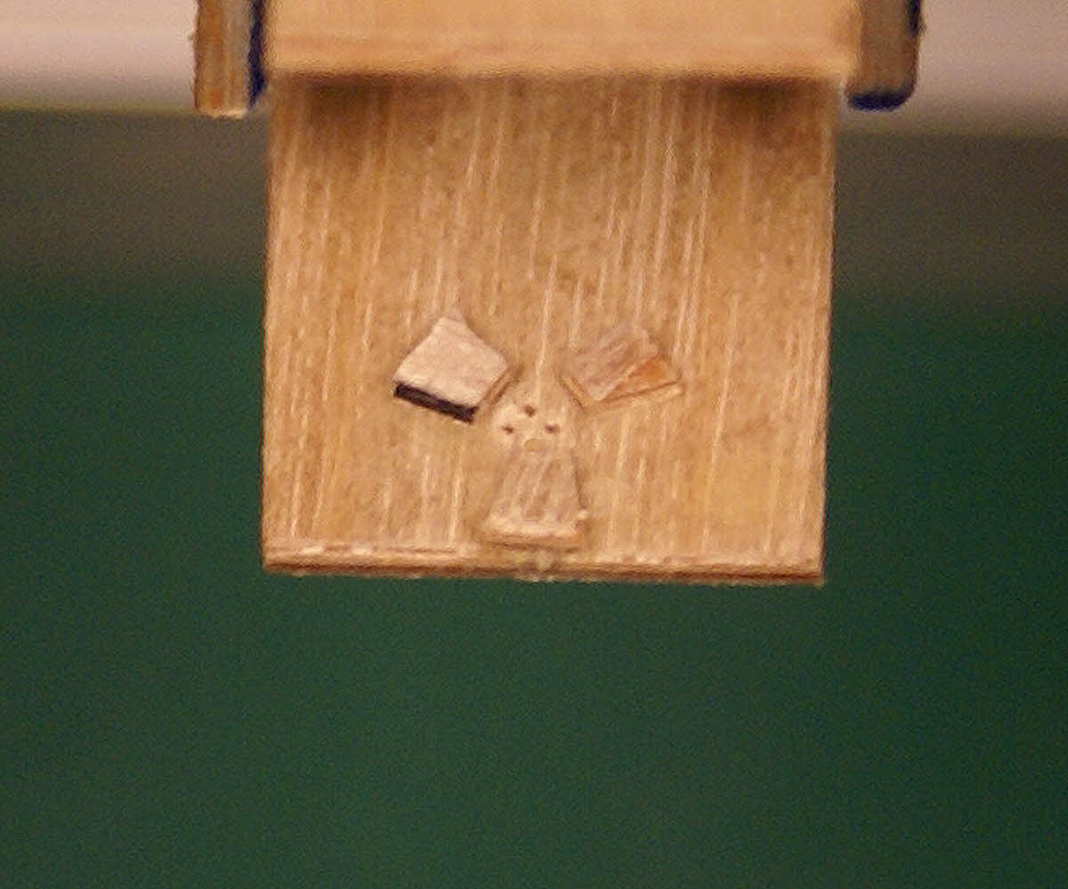
Thank you, Jeff, you're very kind. FIMO is a polymer based modeling compund that doesn't air dry. It can be baked at a low temp (110C/230F) but I've never baked it. It's very similar to Sculpey but it's firmer and a little harder to work. I have heard of others who baked their sea and needed to glue the sea to the bottle. I haven't had that problem with un-baked FIMO. Since I use white FIMO only for a small amount of detail on the surface of the sea, I still have a piece of the first square of white FIMO I bought 35 years ago. I recently bought a new square of white FIMO with a much larger quantity of blue. I cannot tell the difference between the old white and the new in any way. I prefer FIMO Classic over the other types of FIMO, or Sculpey, simply because FIMO Classic has a Navy Blue that is the closest IMO to the color of deep water ocean than any other shade of blue available from either company. If Sculpey came in a shade of blue I liked better, I'd buy Sculpey. I've used both and have no preference other than the color. Colors can be mixed but it's a lot of work. I've been so pleased with the results from using this kind of polymer modeling compound that it's the only material that I have not felt a need to improve upon since building my first SiB over 35 years ago.
- 84 replies
-
- 2
-
-
- esmeralda
- training ship
- (and 1 more)
-
Think nothing of it, Ted. I have twice posted photos with the name right on the photo. First time I caught it myself. Second time someone commented on it but didn't mention the name. Both times I quickly substituted a corrected photo.
-
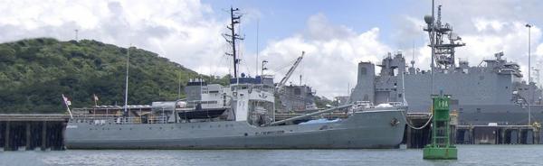
Welcome aboard, Ted, you got it. She is now in Panama's National Maritime Service with the name SMN Independencia (A-401) since 2002. She is used primarily as a tender for Panama's fleet of coastal patrol vessels. Here's a recent photo of her: By the way, this is the tenth mystery ship in a row I have posted that at one time or other in their history had the name Independence going back to Atzmaut (Hebrew for Independence) and the 12th including the USS Independence, the United States' first ship of the line (posted by me), and the Texas First Navy cutter Independence (posted by Kevin from Hampton Roads) in recent months. The latter was the ex-US Revenue Cutter Ingham that was the source of the Coast Guard's motto Semper Paratus - Always Ready. I think this is a good time to end the string of Independences. Your turn, Ted. You coasties don't always get the recognition and respect you deserve - thank you very much for your service.
-
It's been a week and no more guesses have been posted so I'll recap what is known: It's a 180' buoy tender (the only USCG vessel to have classes) built during WW2. 39 of them were built. It's one of the 6 "B" or Mesquite class. It's still in existence and in service in the navy of a small country. Down from 6 to 2. The name does not begin with "B" which eliminates 1 - leaving only 1 possibility.