Glenn-UK
-
Posts
3,170 -
Joined
-
Last visited
Content Type
Profiles
Forums
Gallery
Events
Everything posted by Glenn-UK
-
 Looks a very nice model, one to bear in mind along with the Indy once I have completed Sphinx, Erycina and Saucy Jack. I hoping to complete the Sphinx by the end of this month then I will be starting on the two fishing boats
 -
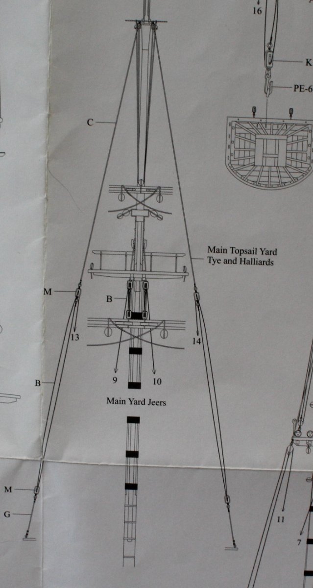
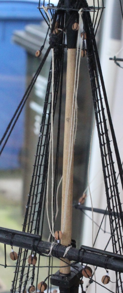
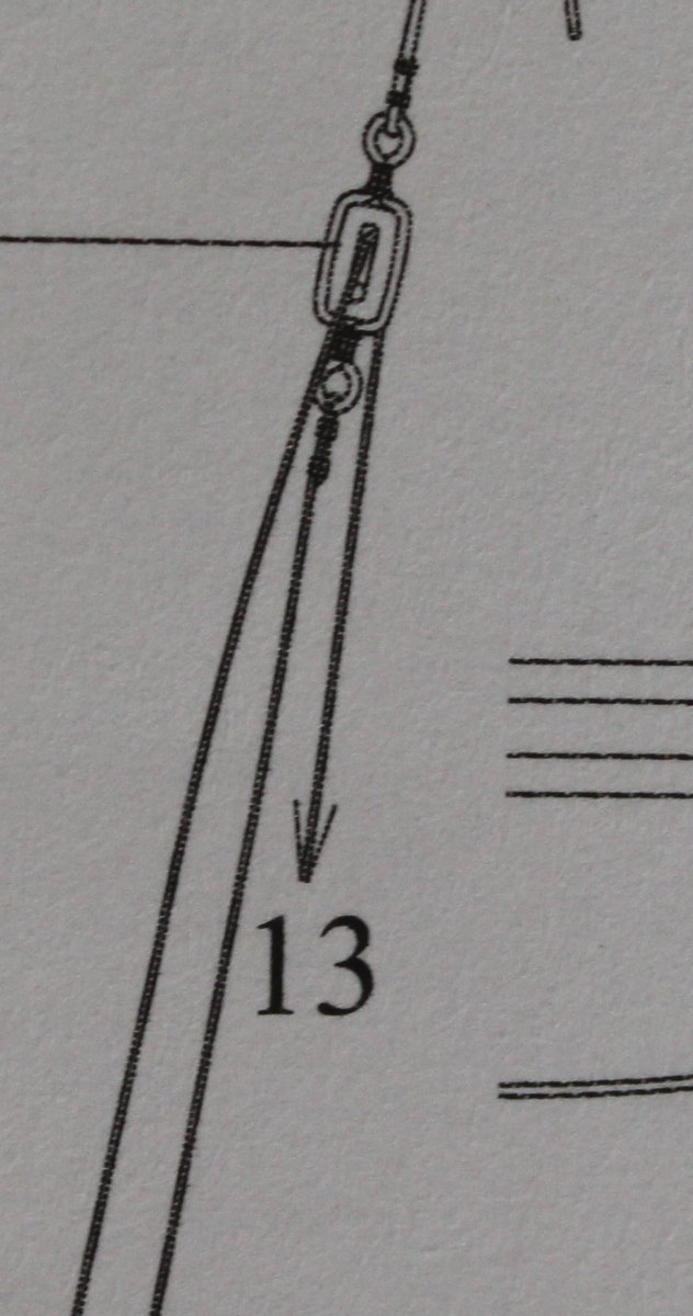
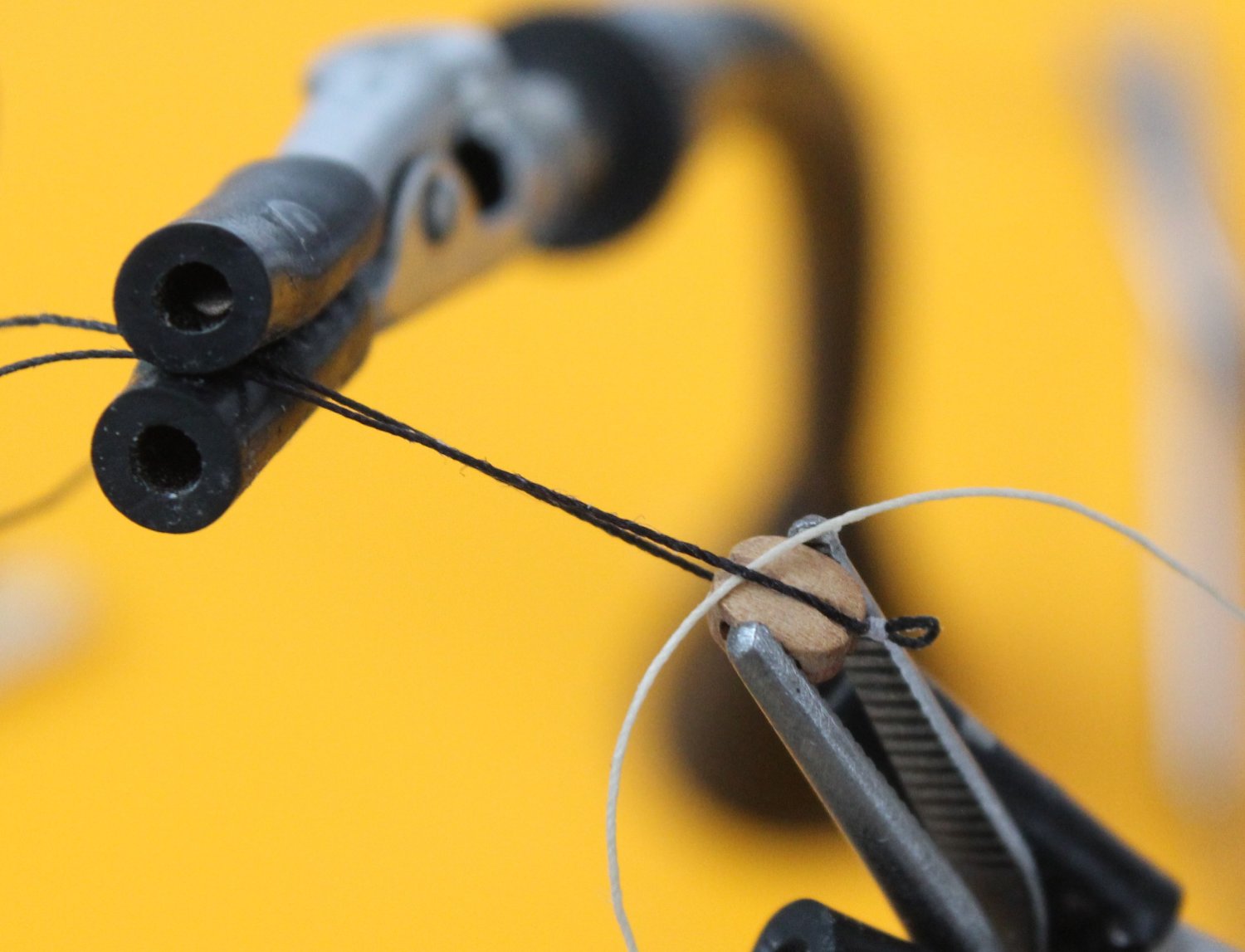
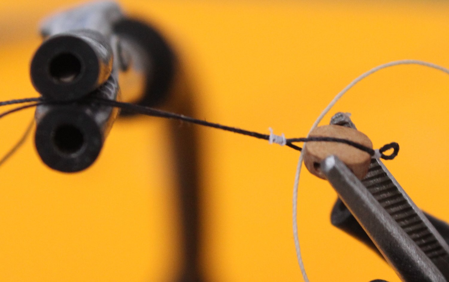
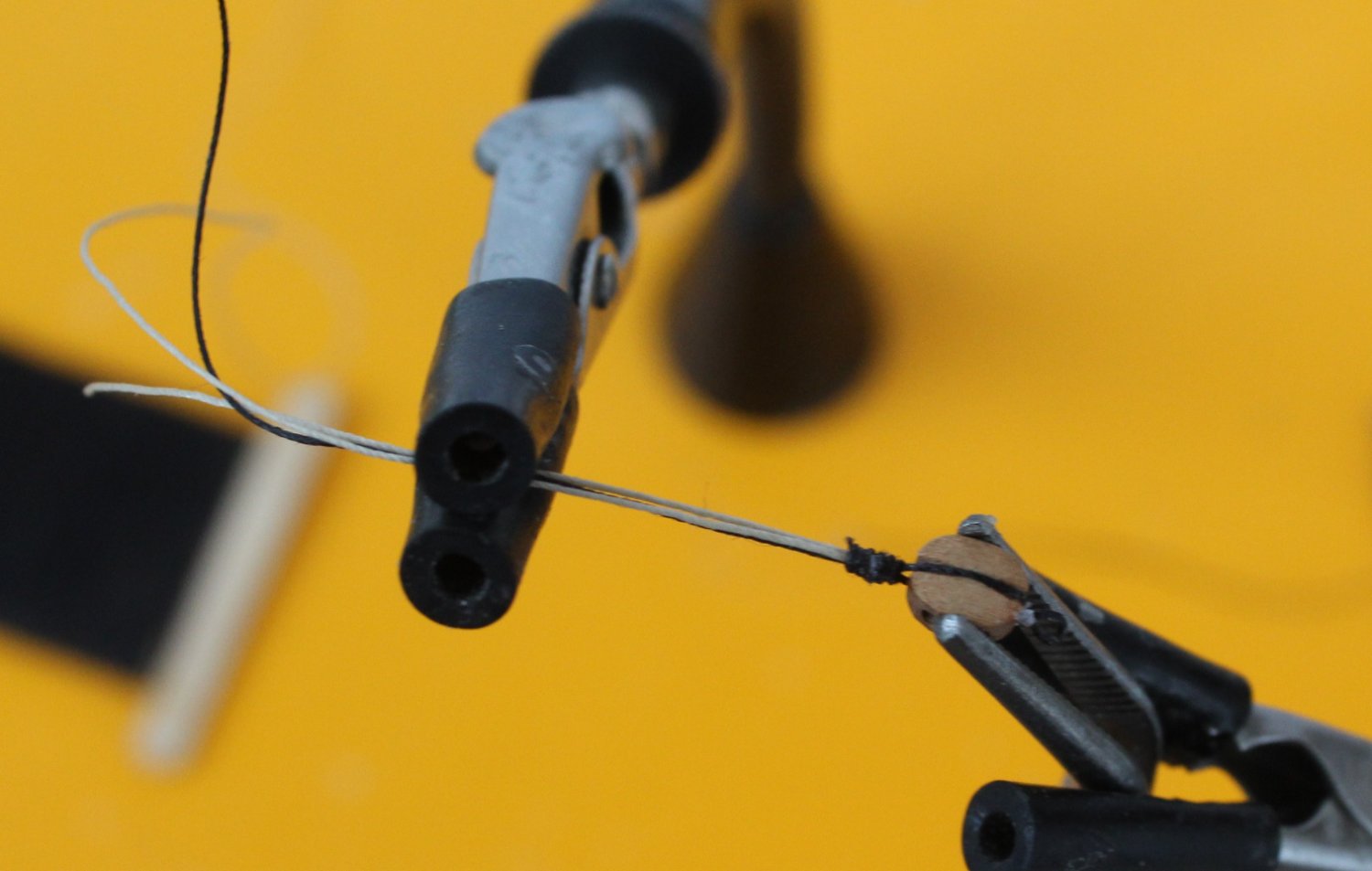
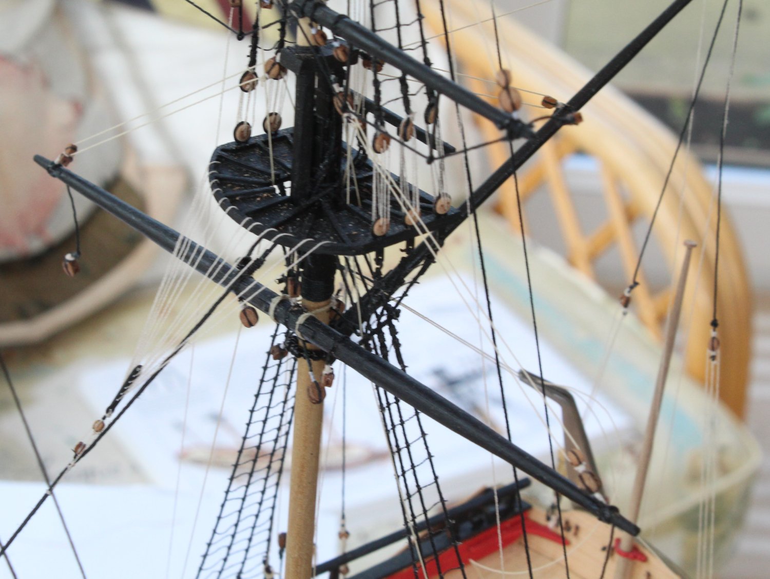
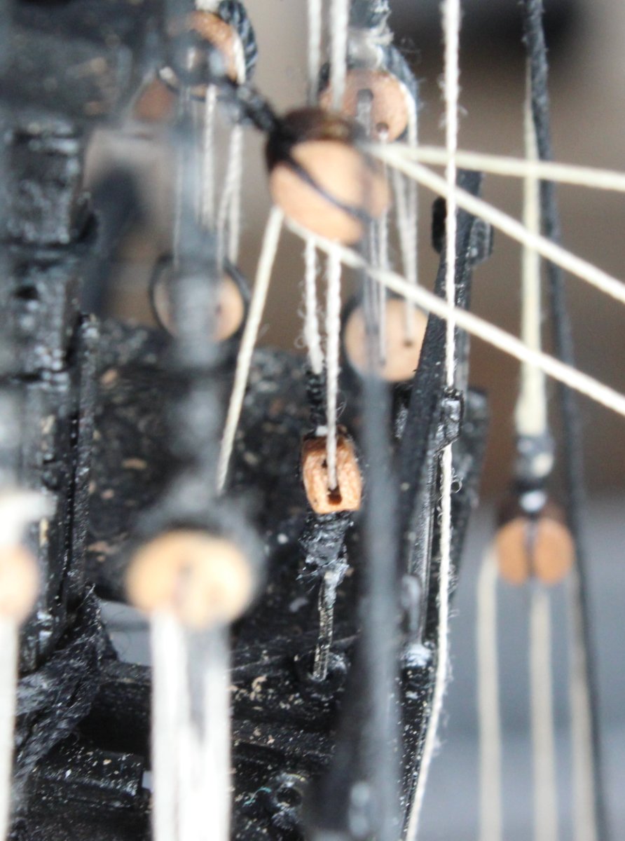
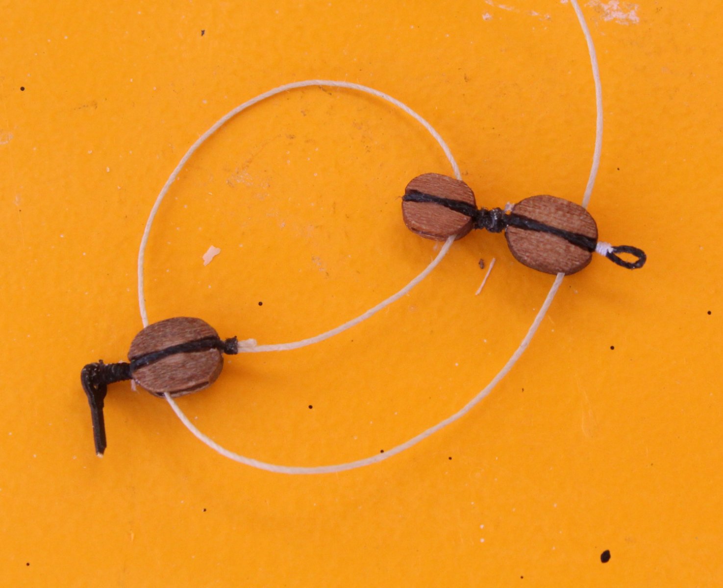
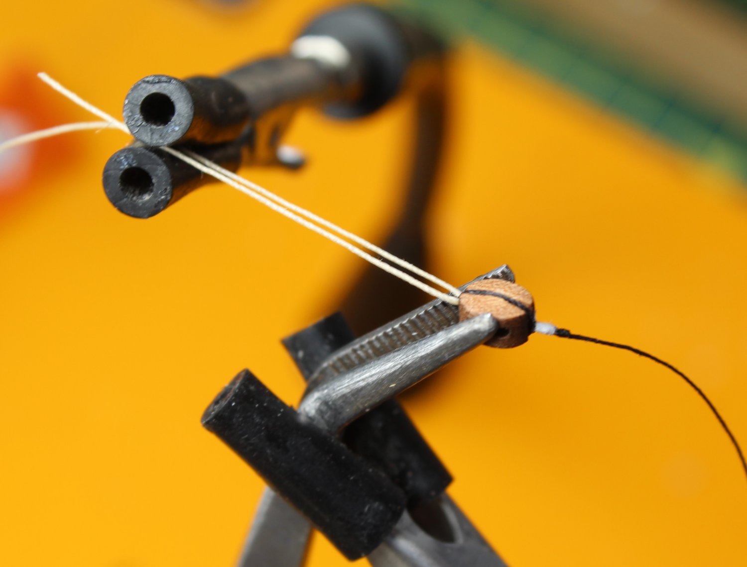
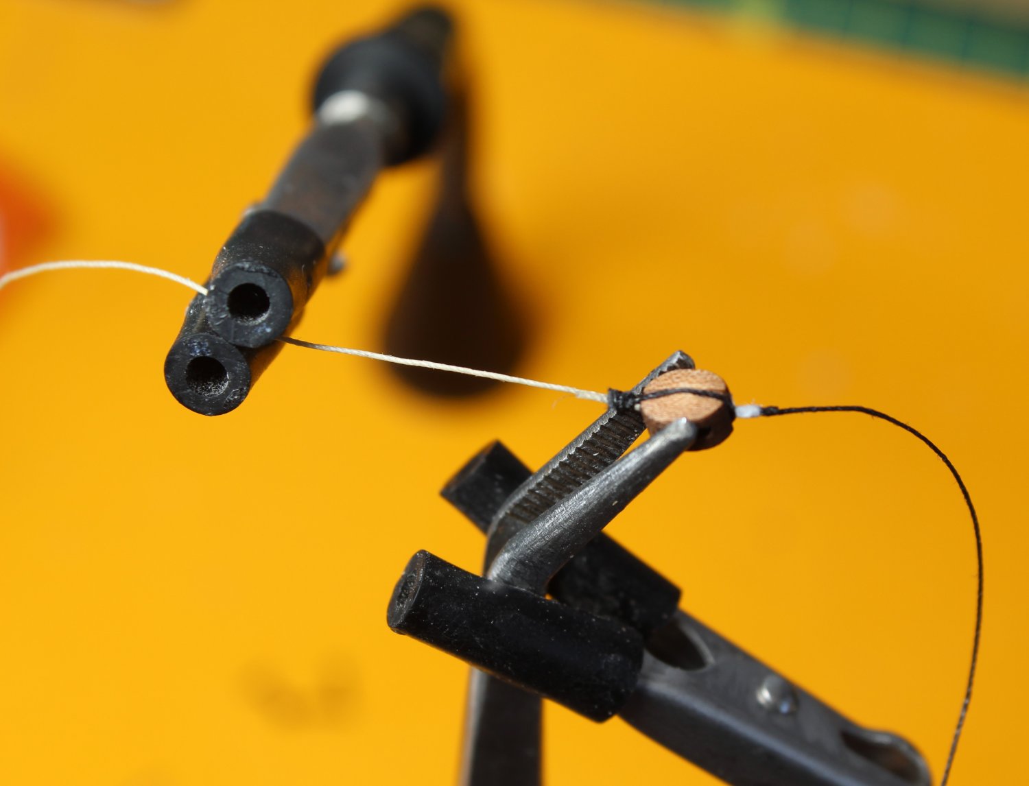
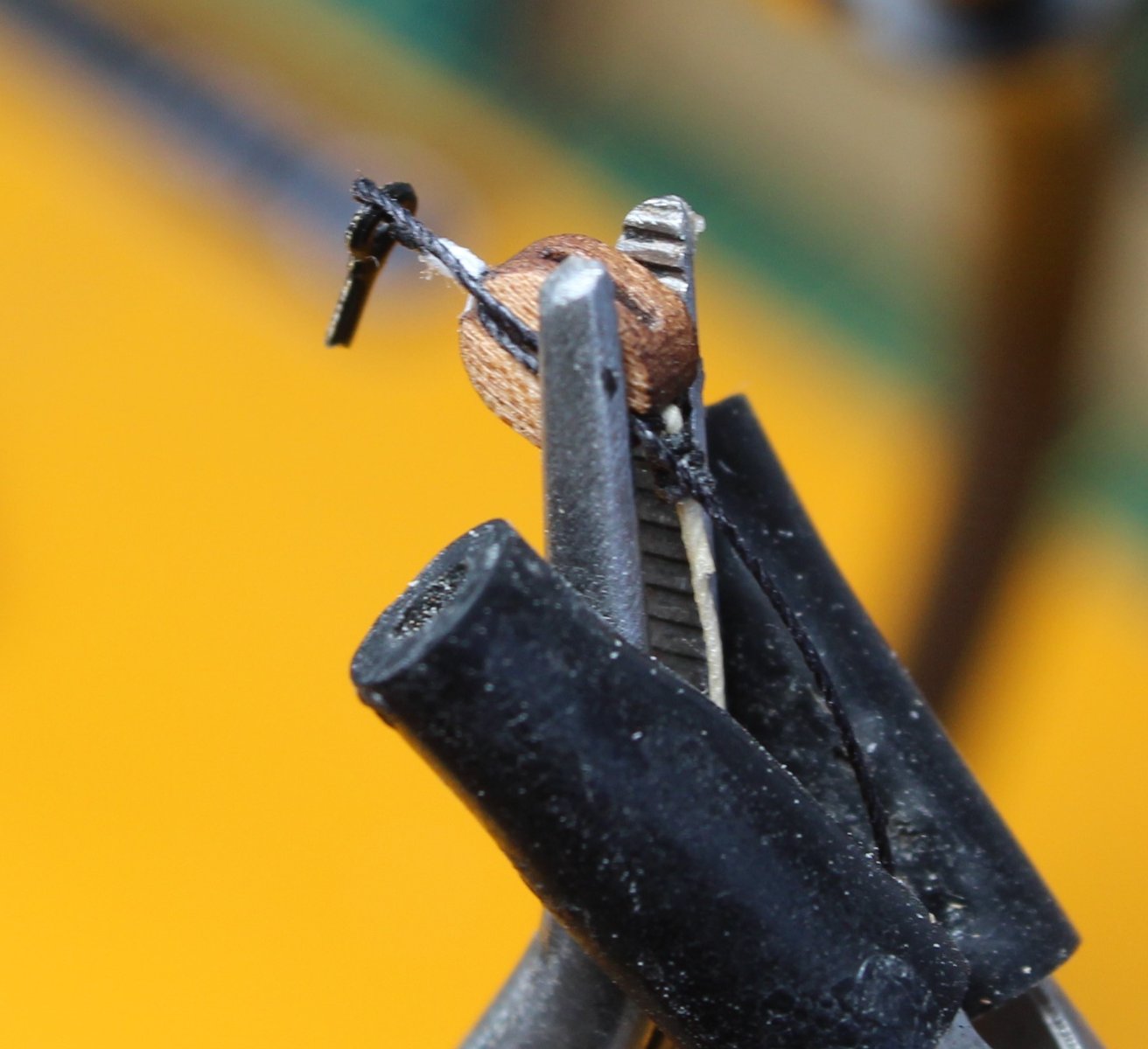
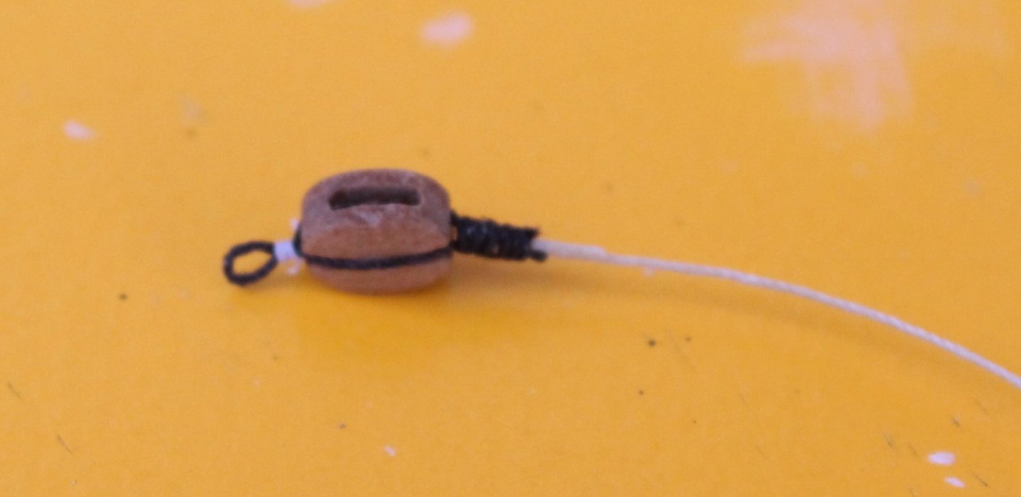
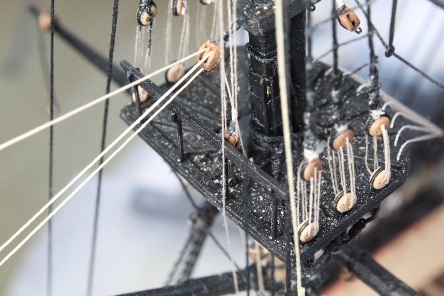
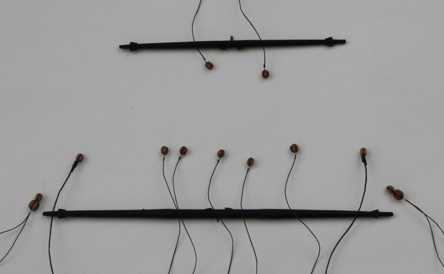
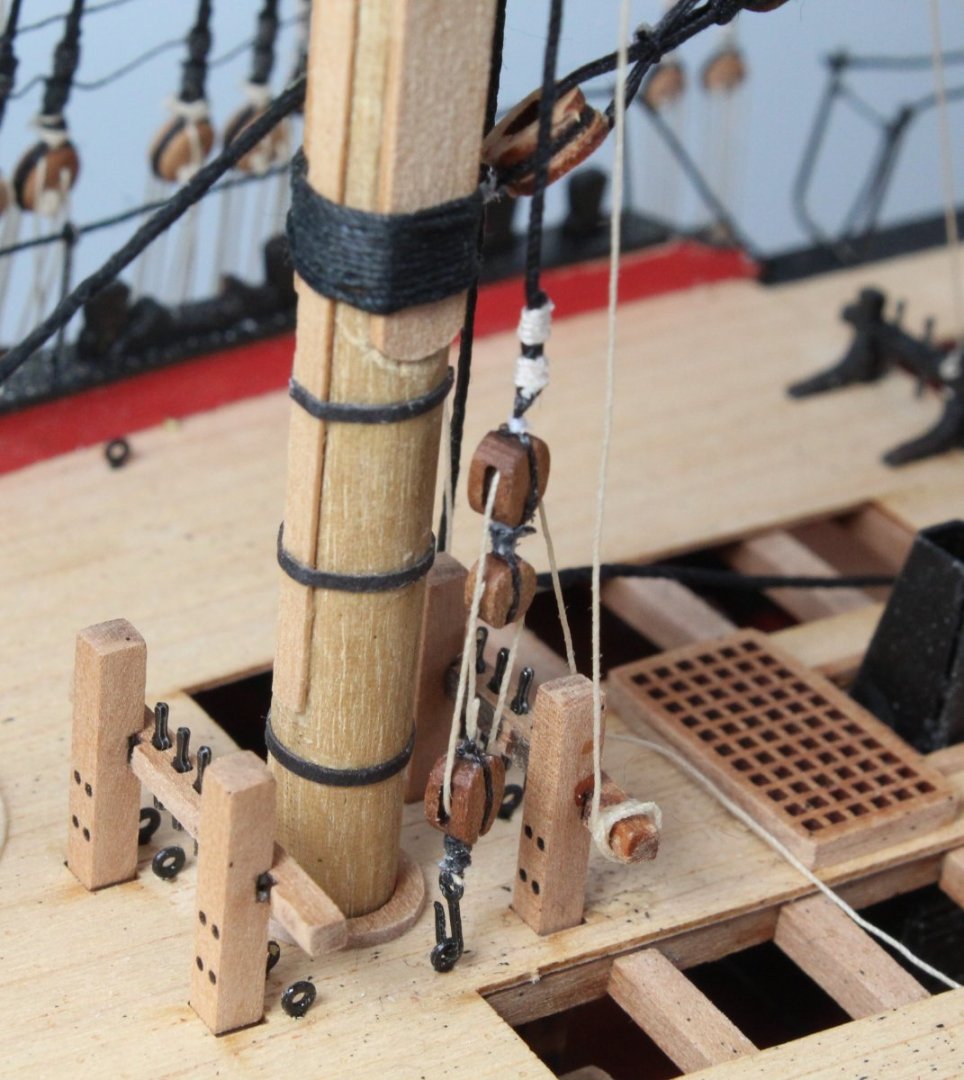
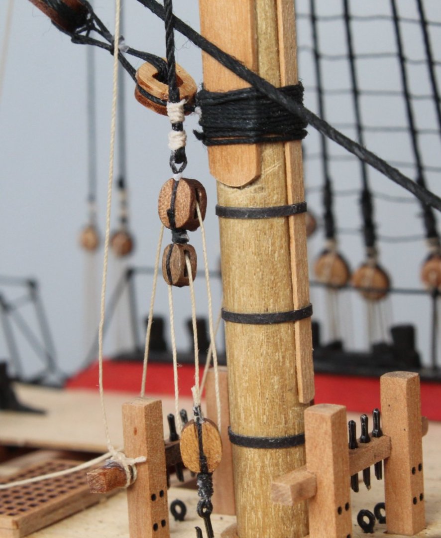
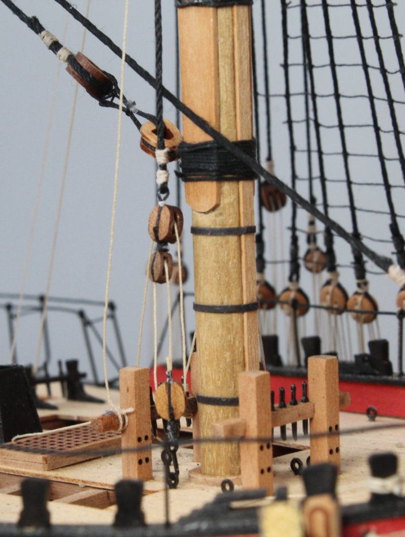
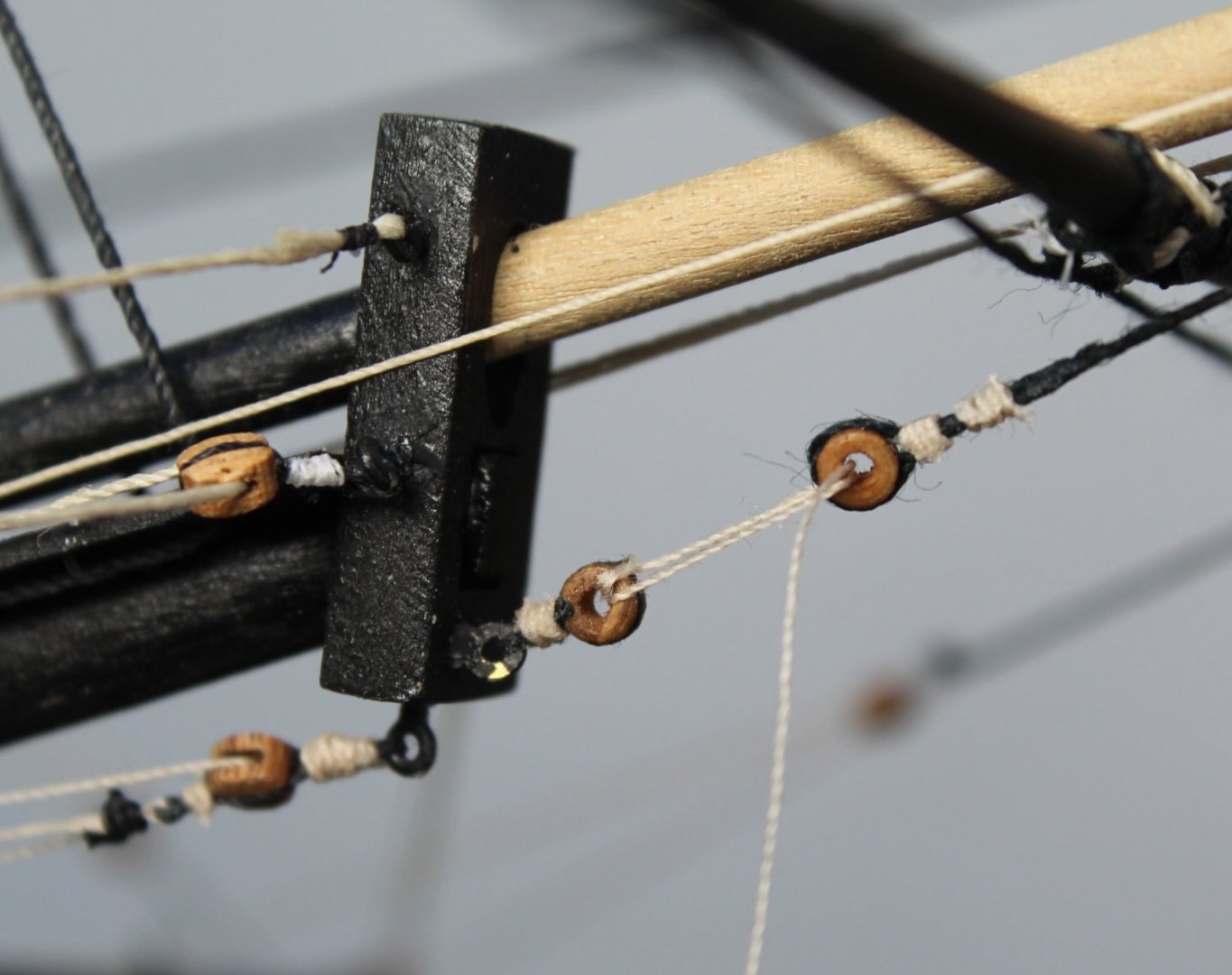
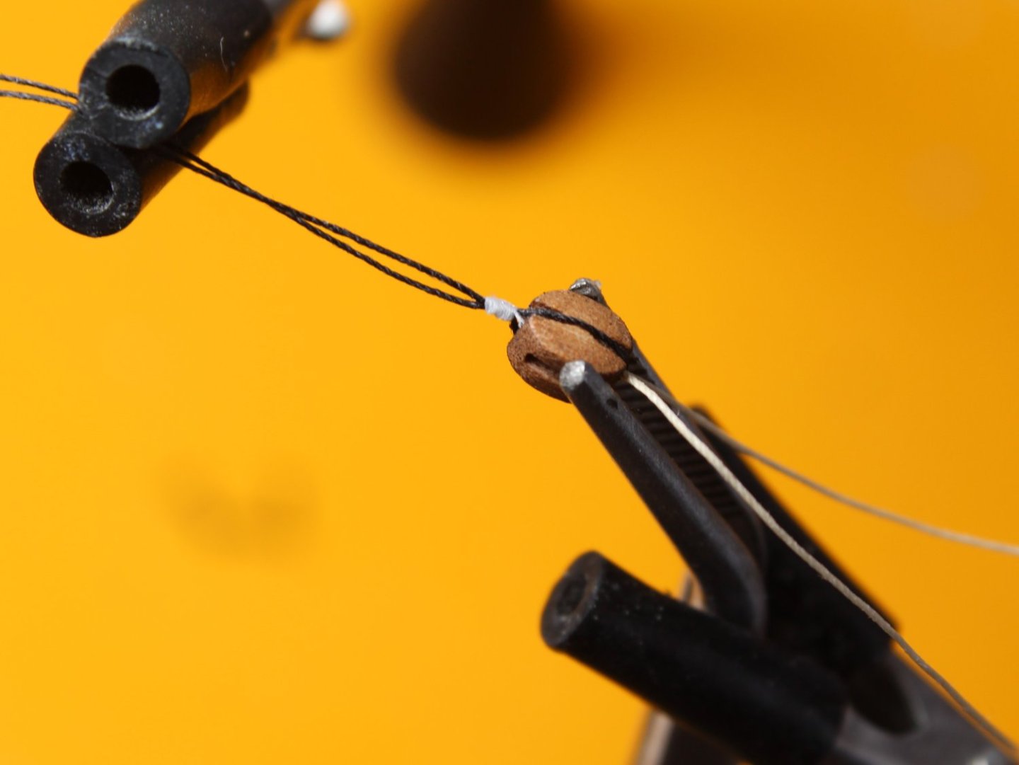
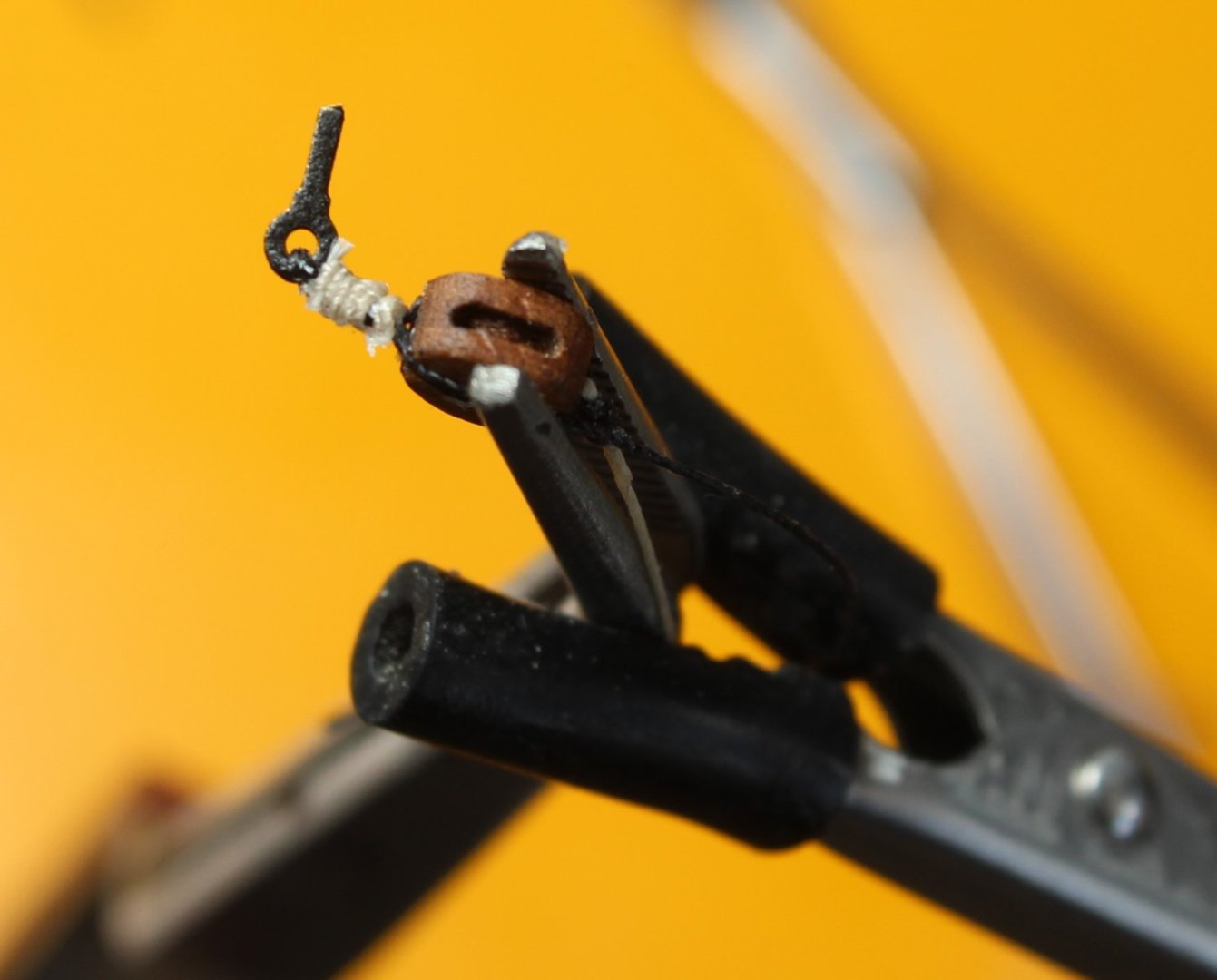
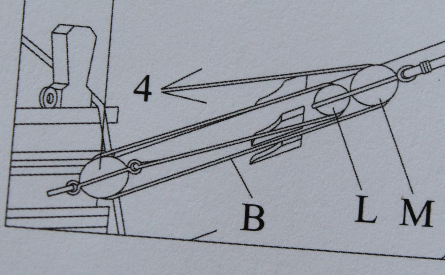
Main Topsail Yard Tye and Hilliard The photo below shows the rigging plan for this task. Two lengths of 0.5mm natural thread are secured to the leading topmast crosstrees. These threads are then passed through the central double block located on the topsail yard. The two threads return to the topmast platform and are fed through single blocks. The two free ends are then secured to single 5mm blocks. A second set of 5mm single blocks are then secured to the main mast channel using eyebolts. 0.25mm natural thread is used to join the two blocks together. I took two lengths of 0.5mm natural thread and ran them through the central double block on the yard and to the two 3mm single blocks on the upper crosstrees. This is shown on in the photo below, noting the free ends are still to be belayed so the rigging is not very taut Close up of the central double block The free ends of these threads are then belayed to 5mm single blocks. I thought I would detail the method I used to seize one of the blocks. It might not be the correct method, but it is a method which I have found to be relatively easy do and does produce a passable end result (in my opinion). The picture below shows the block arrangement required and as can be seen there are two thimbles required (top and bottom). Starting with a length of 0.25mm black thread I create the upper thimble. A large loop is formed and is then held in place using my quad hands. The seizing is the applied using fly tying thread. As detailed in some of my previous posts all seizing is done using a series of half hitch knots (top and bottom). As the created loop is over sized it is then placed over a metal pin and closed up by pulling the two free thread ends. This is shown in the photo below. With the top thimble created the thread is then wrapped around the 5mm single block, taking care to ensure the upper thimble is correctly positioned with the block. With the two free ends of the seizing thread held firm in the quad hands a long length of 0.25mm natural thread is added. This arrangement is shown in the next photo. Using flying thread, the bottom thimble is formed, as can be seen in the following photo. The two free ends of the seizing thread are then pulled so the seizing can be pull up tight against the 5mm block which is shown in the next photo. One of the seizing thread ends is trimmed away so that the 0.25mm natural thread can be placed alongside the remaining seizing thread. This arrangement is then held in place with the quad hands, as shown in the next photo. To complete the process the natural thread is seized to the remaining black thread end, as shown in the photo below. I opted to use the black ratline thread for this. I hope you found this post of some interest. The competed block is now ready to be added to the Sphinx.


- 476 replies
-
- 6
-

-
- sphinx
- vanguard models
- (and 1 more)
-
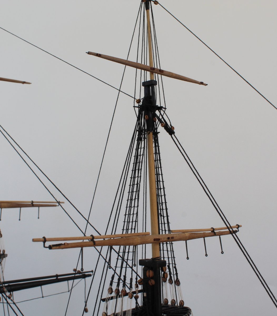
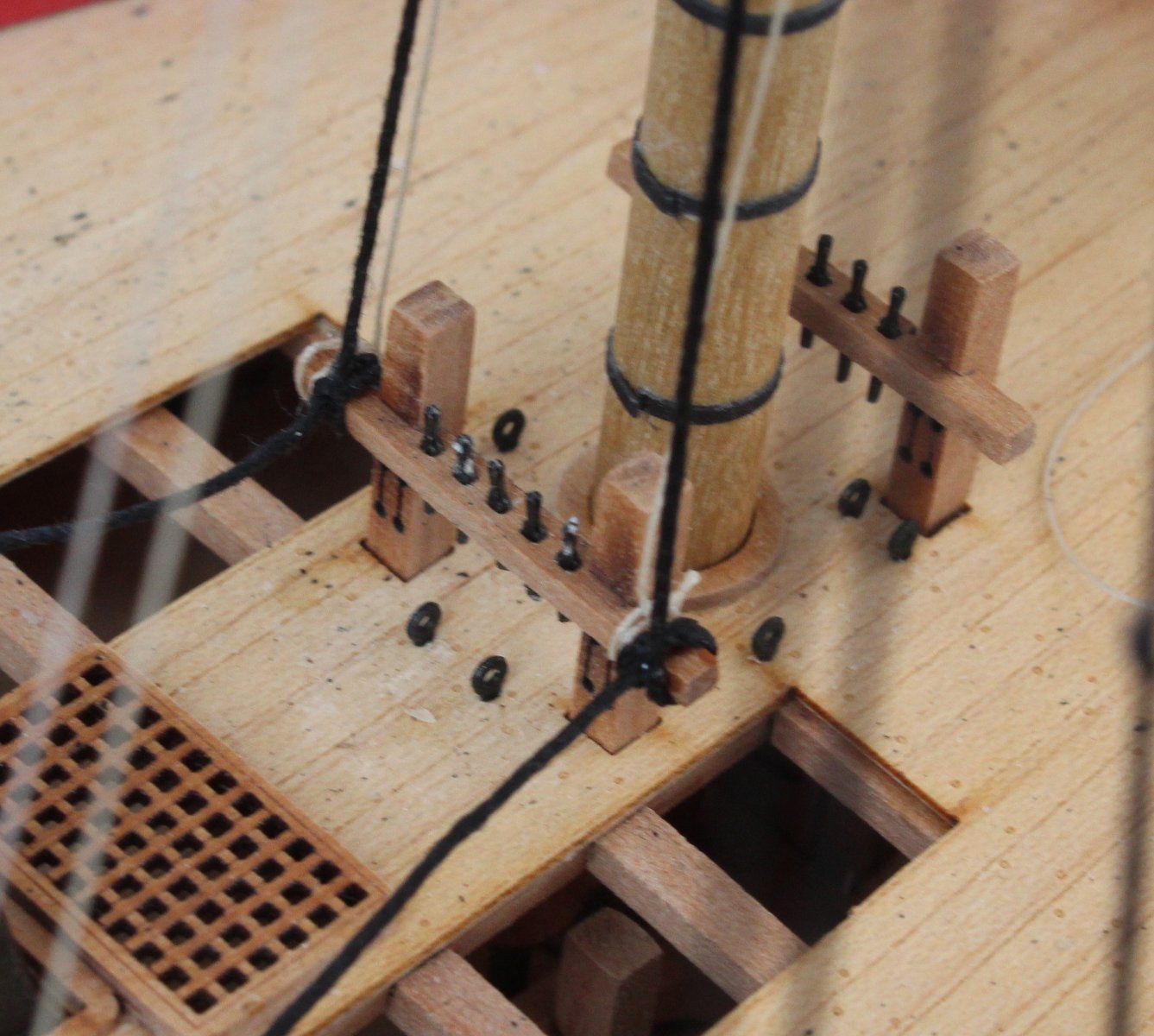
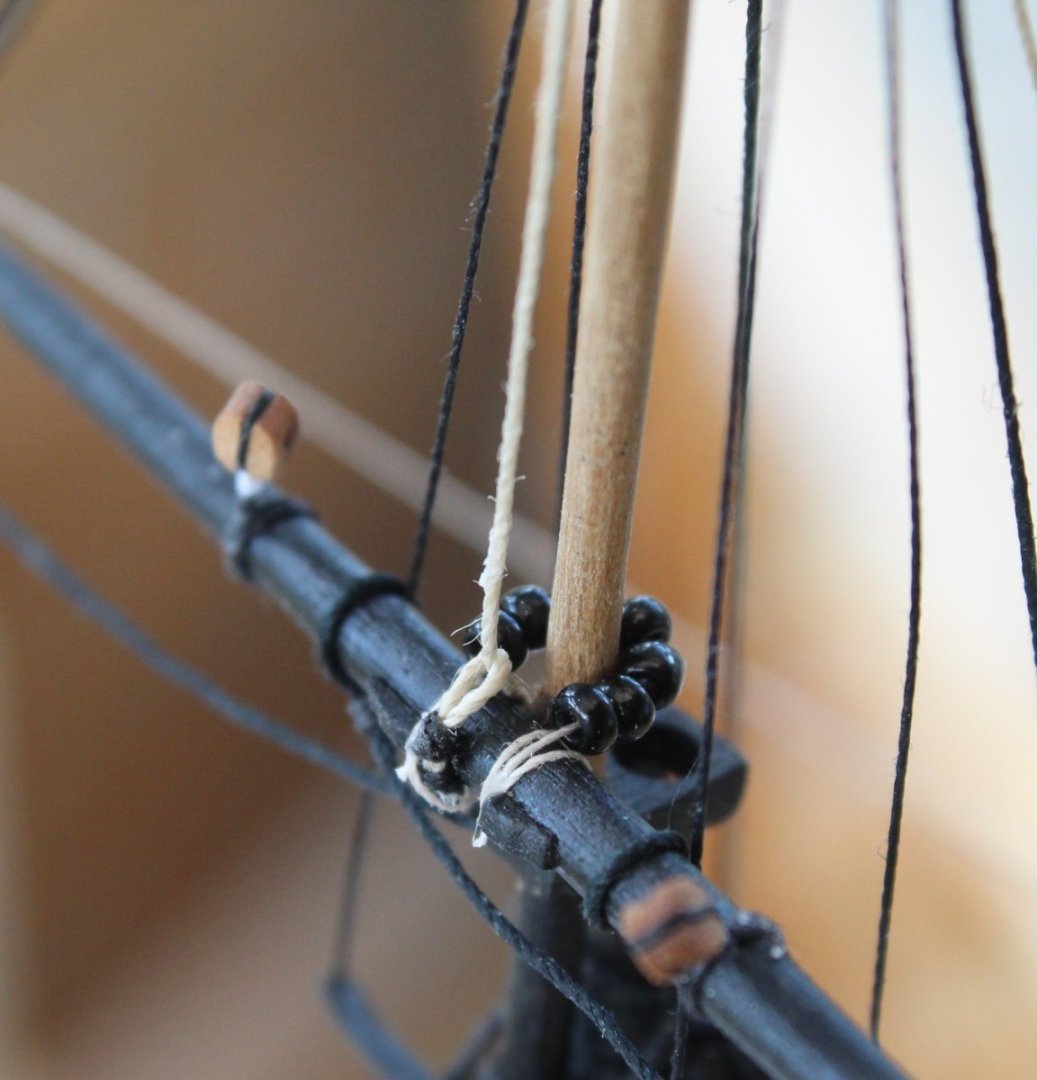
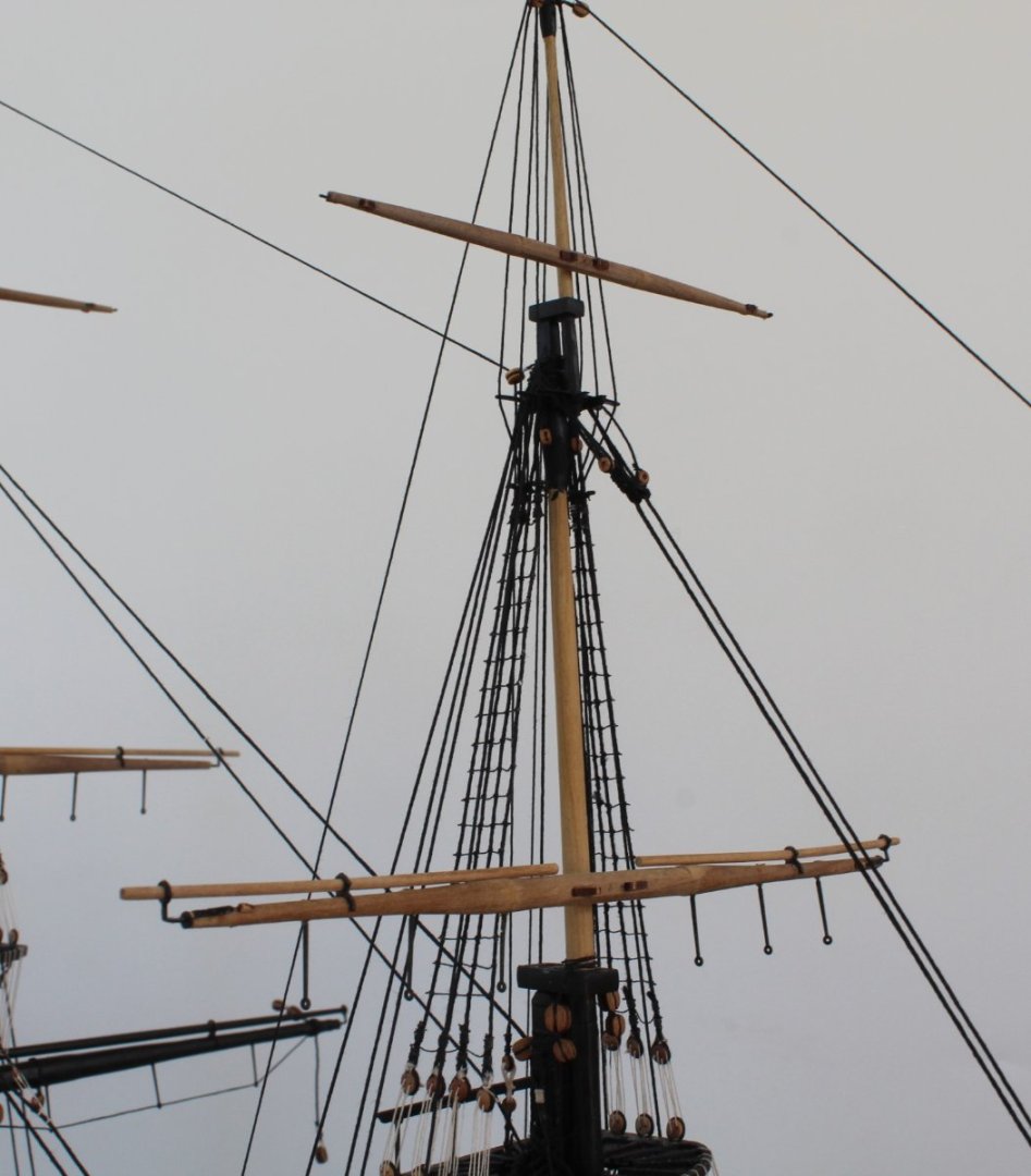
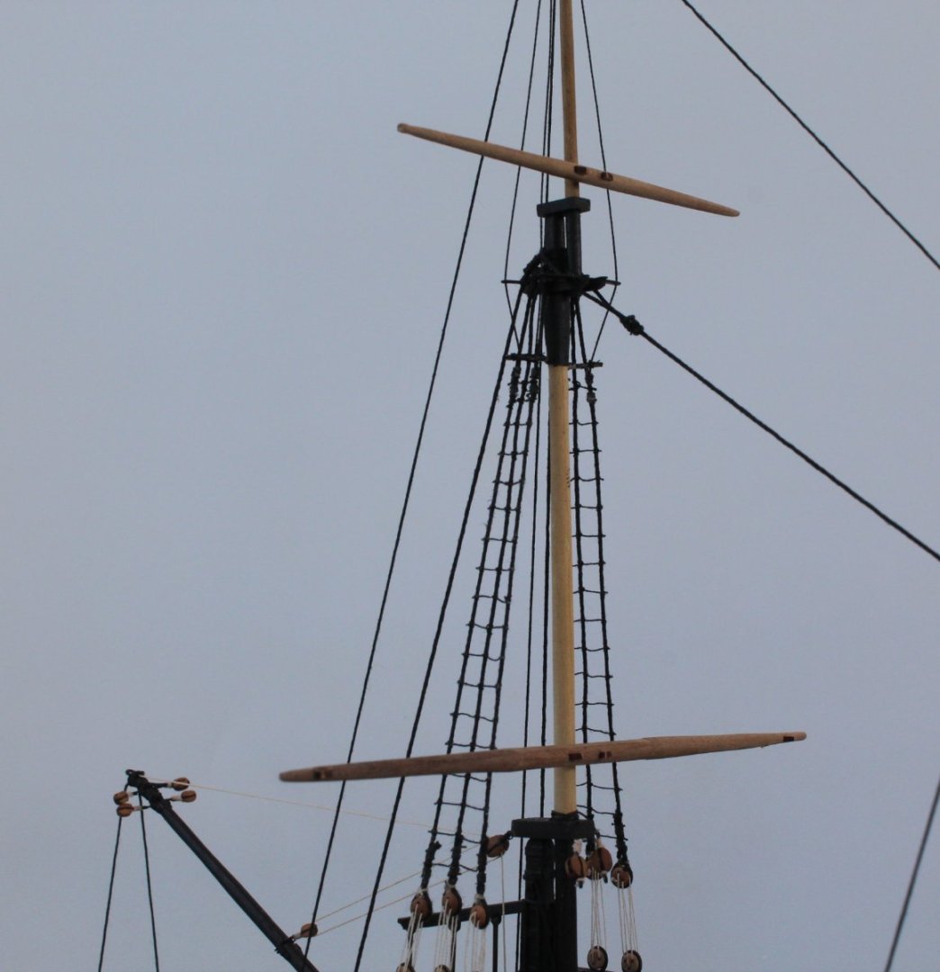
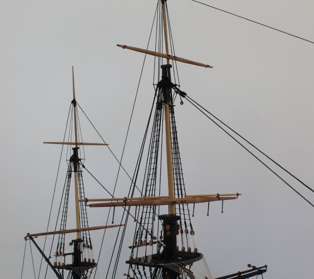
Mizzen Yard Braces This morning I added the braces to the mizzen crossjack, top and topgallant yards. I have not belayed the free ends of these braces which I will do once I have secured the main and fore top and topgallant yards to their respective masts. As I have moved the build to a different location in the shipyard for better all-round access it is much harder to get good quality photos. The first photo shows the crossjack yard braces. You may note some reverse action tweezers in the photo. I am using these to keep some tension in the various braces before I belay the free ends to the pin rack on the mizzen mast. The next photo shows the topyard braces. The free ends will be belayed to cleats located on the leading mizzen mast shroud line. The next photo shows the topgallant yard braces. The free ends will be belayed to cleats located on the topmast shroud. The next photo shows the mizzen mast in full. My IJN Yamato (Model Space) can be seen in the background. I am now working on securing the remaining yards to the masts. The final picture shows the main topyard which has been secured to the topmast using parrel ribs and beads.


- 476 replies
-
- 6
-
-
- sphinx
- vanguard models
- (and 1 more)
-
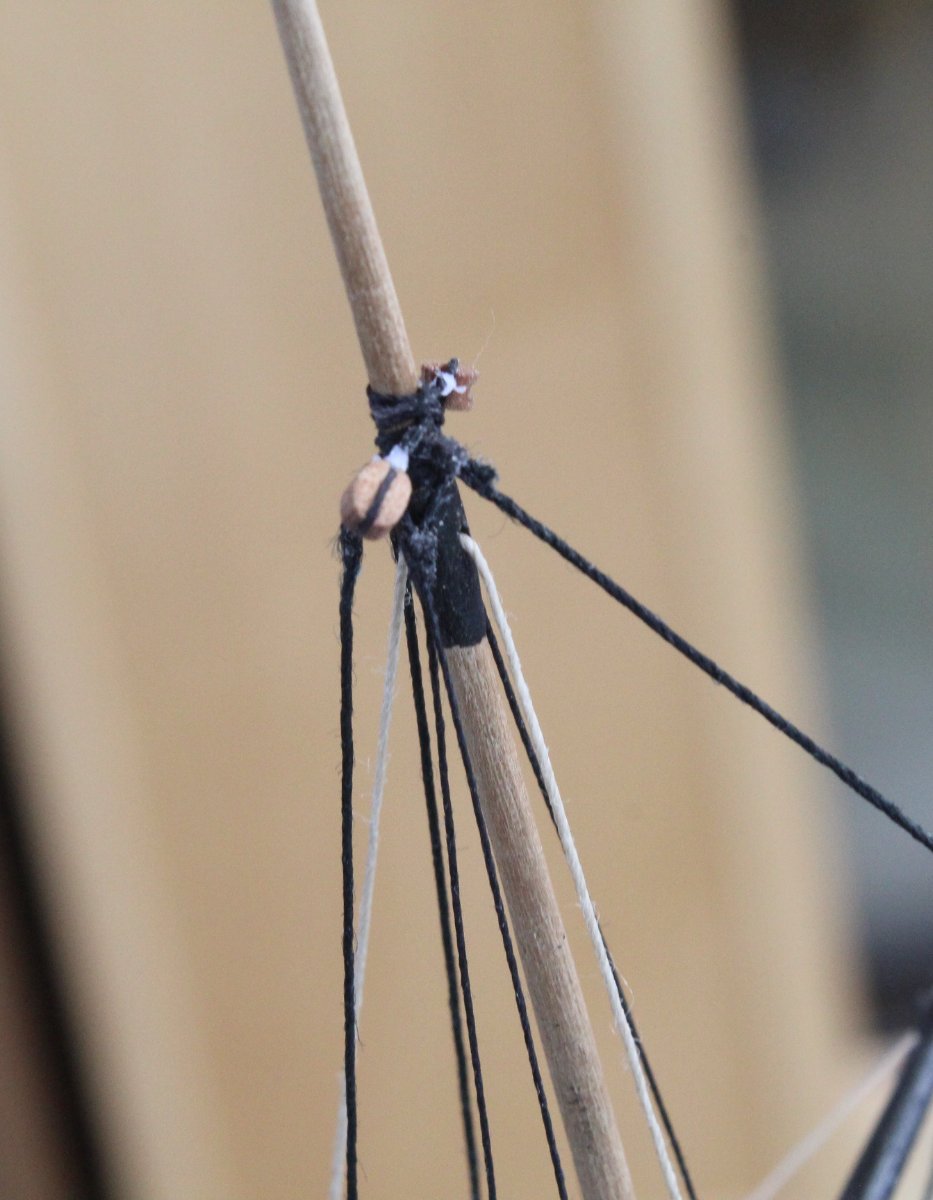
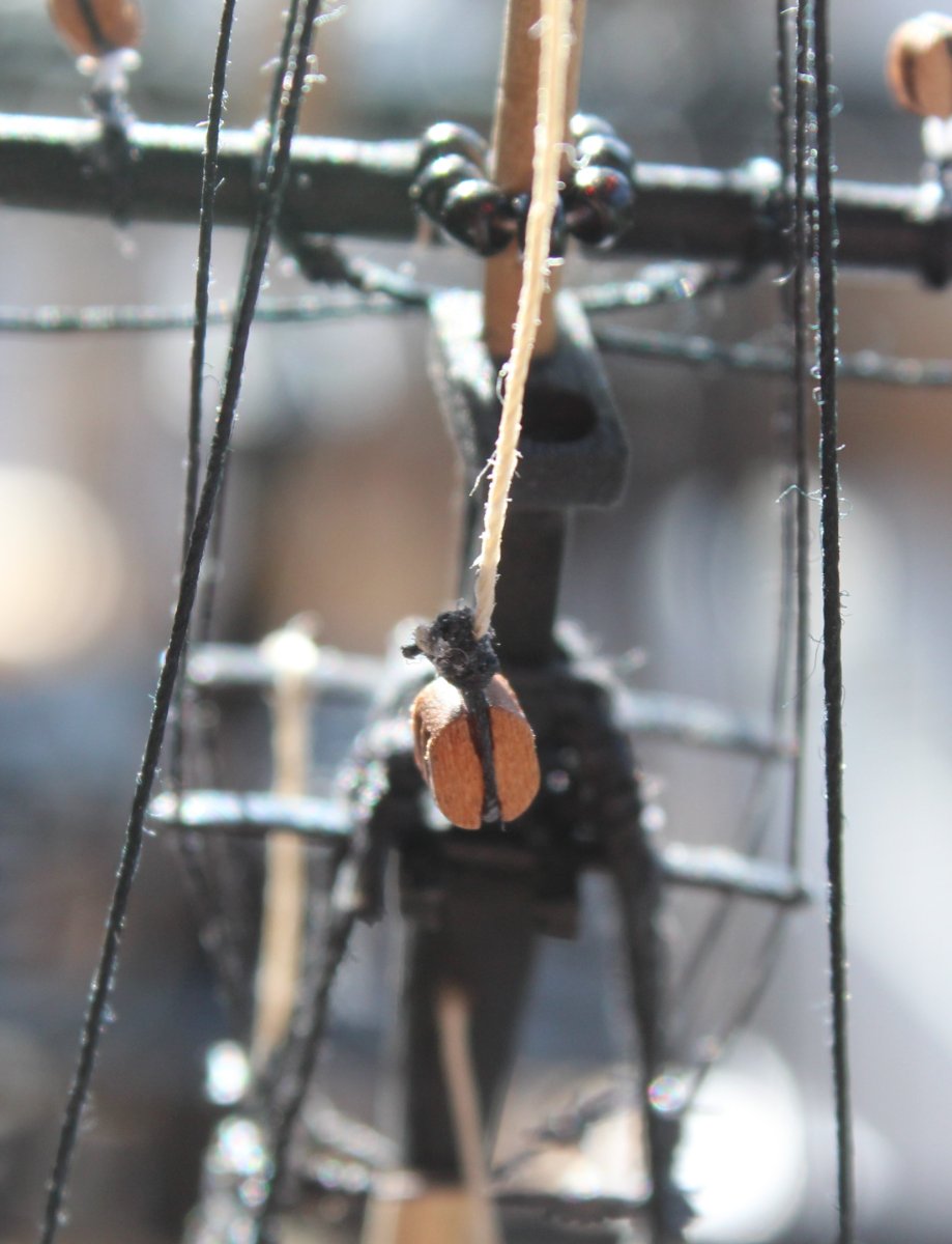
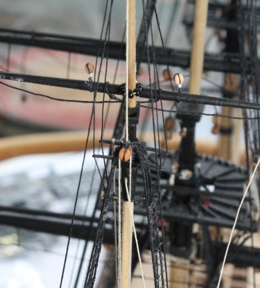
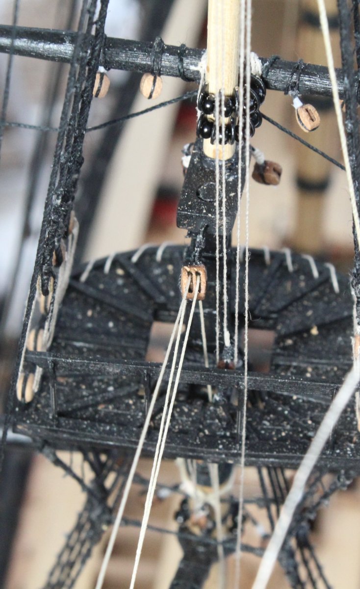
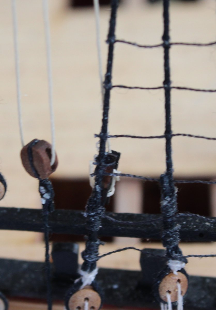
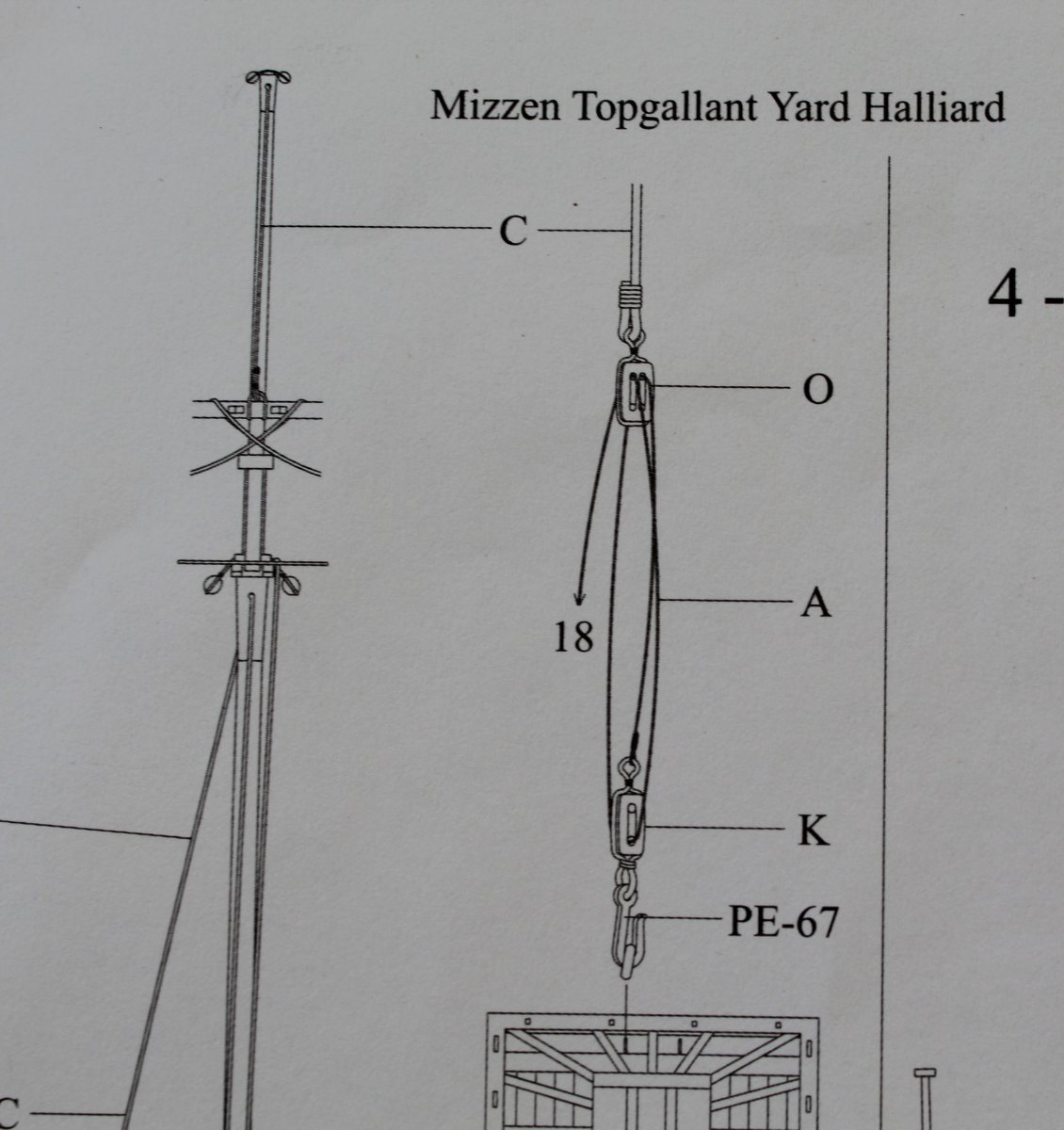
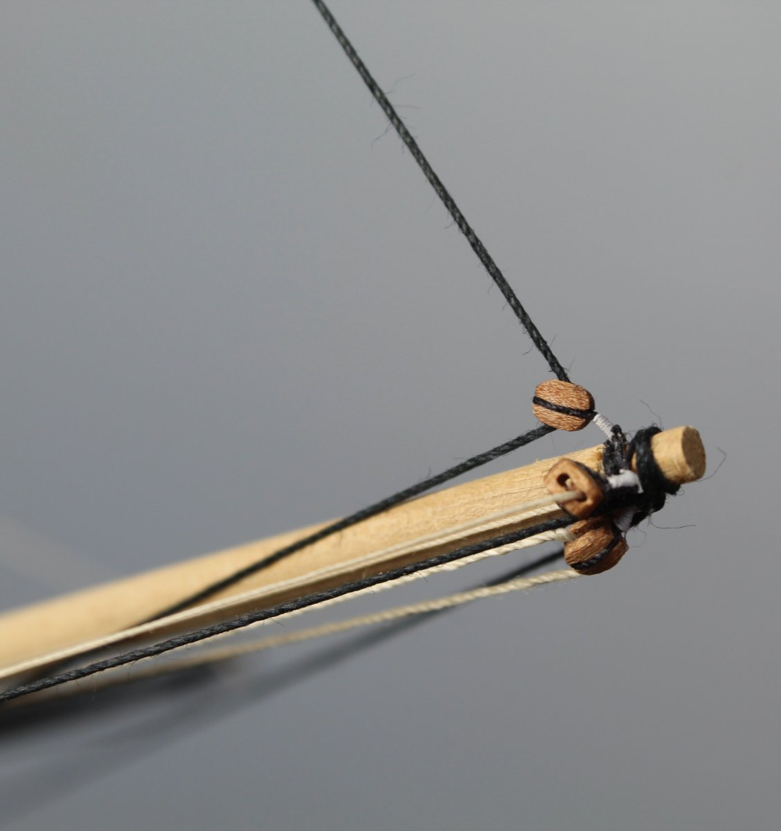
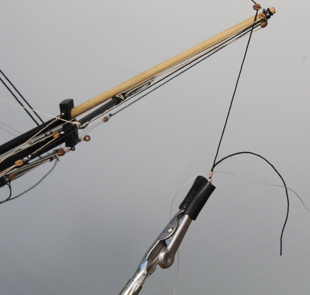
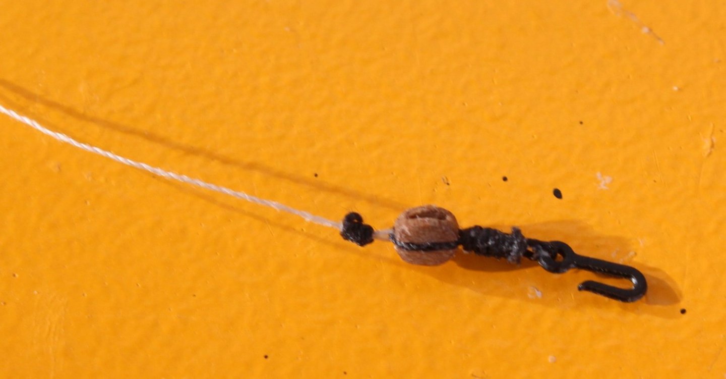
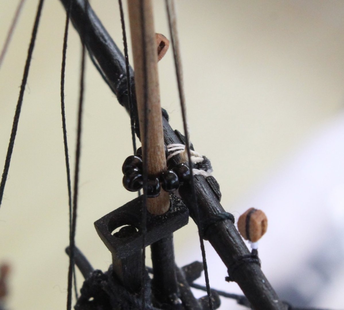
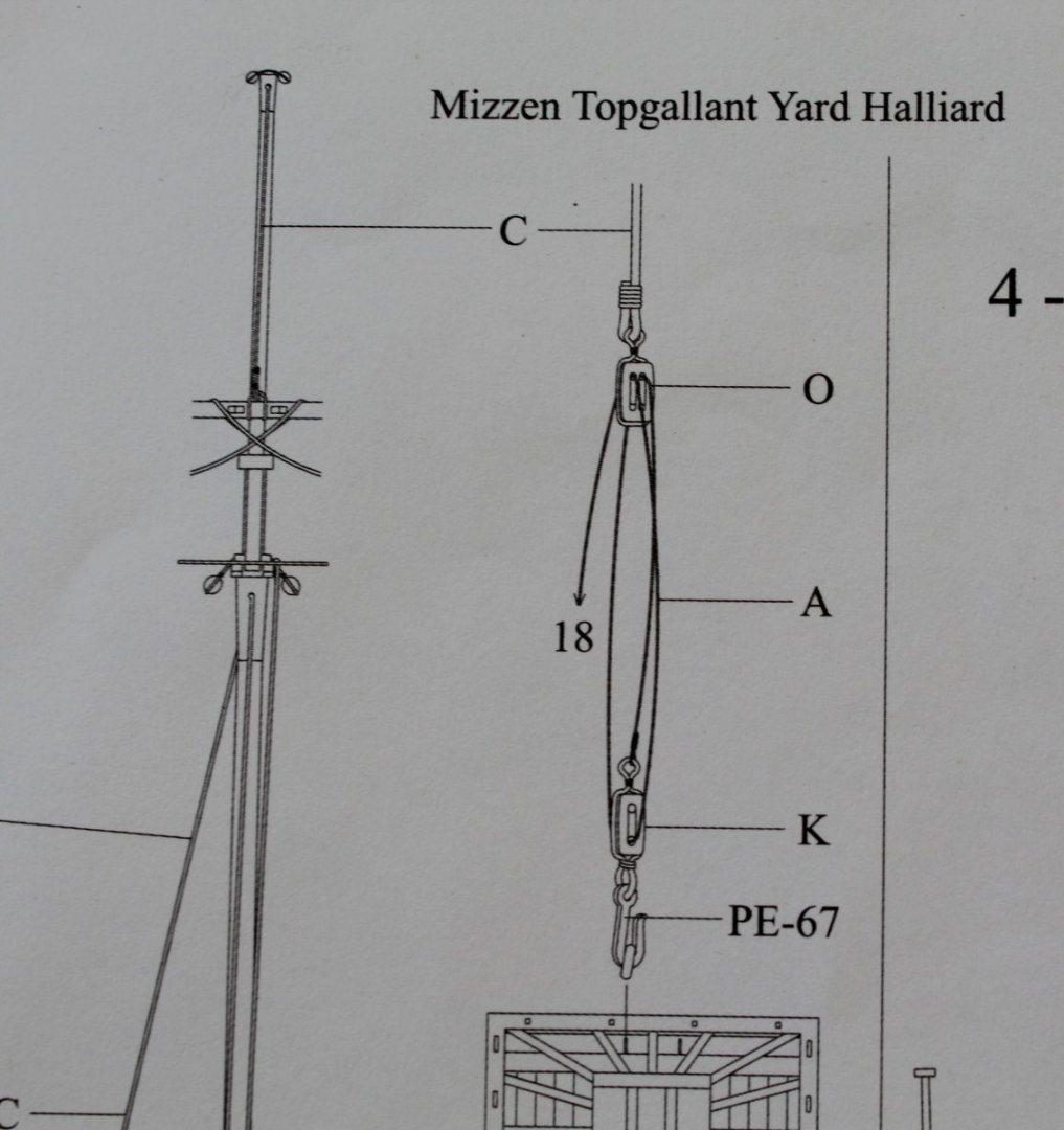
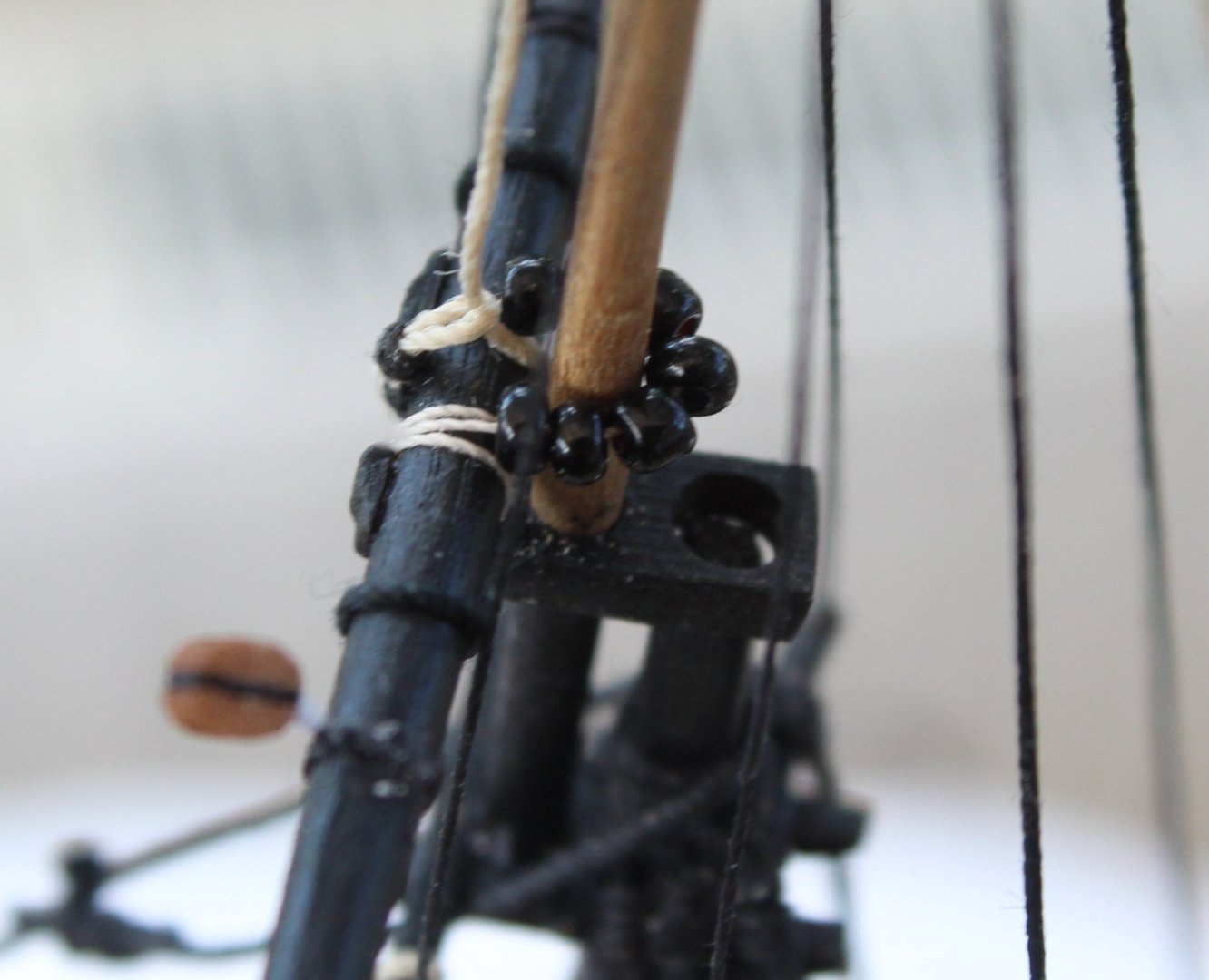
Following on from my earlier post I added the cleat to the mizzen shroud. I then belayed the free thread end of the mizzen topyard hilliard rigging to the newly added cleat, as can be seen in the photo below. Mizzen Topgallant Yard The mizzen topgallant yard is to be secured to the topgallant mast using parral beads. I used a spare piece of dowel to work out how many parral beads were required. It was a fairly straightforward task to add the threaded parral beads to secure the topgallant yard to its mast. The following picture shows the required rigging for the topgallant yard hilliard. The hilliard thread was secured to the yard as can be seen in the next two photos. The hilliard thread was then fed through the hole in the topgallant mast as can be seen in the next two photos. The next task was to add a double 4mm block to the end of the hilliard thread, as shown below. As was shown on the plan sheet a single 3mm block, complete with a hook, is to be added to an eyebolt on the mizzen mast platform. The next photo shows the block arrangement, before it was fitted in place. A long length of 0.1mm thread was also seized to a thimble on the other end of this block. I was then able to add the hook to platform eyebolt without any problems as can be seen in the next two photos The final two photos in this post shows the completed rigging between the two blocks. The free end is ready to be terminated to a belaying pin on the rack fitted near the base of the mizzen mast


- 476 replies
-
- 7
-
-
- sphinx
- vanguard models
- (and 1 more)
-
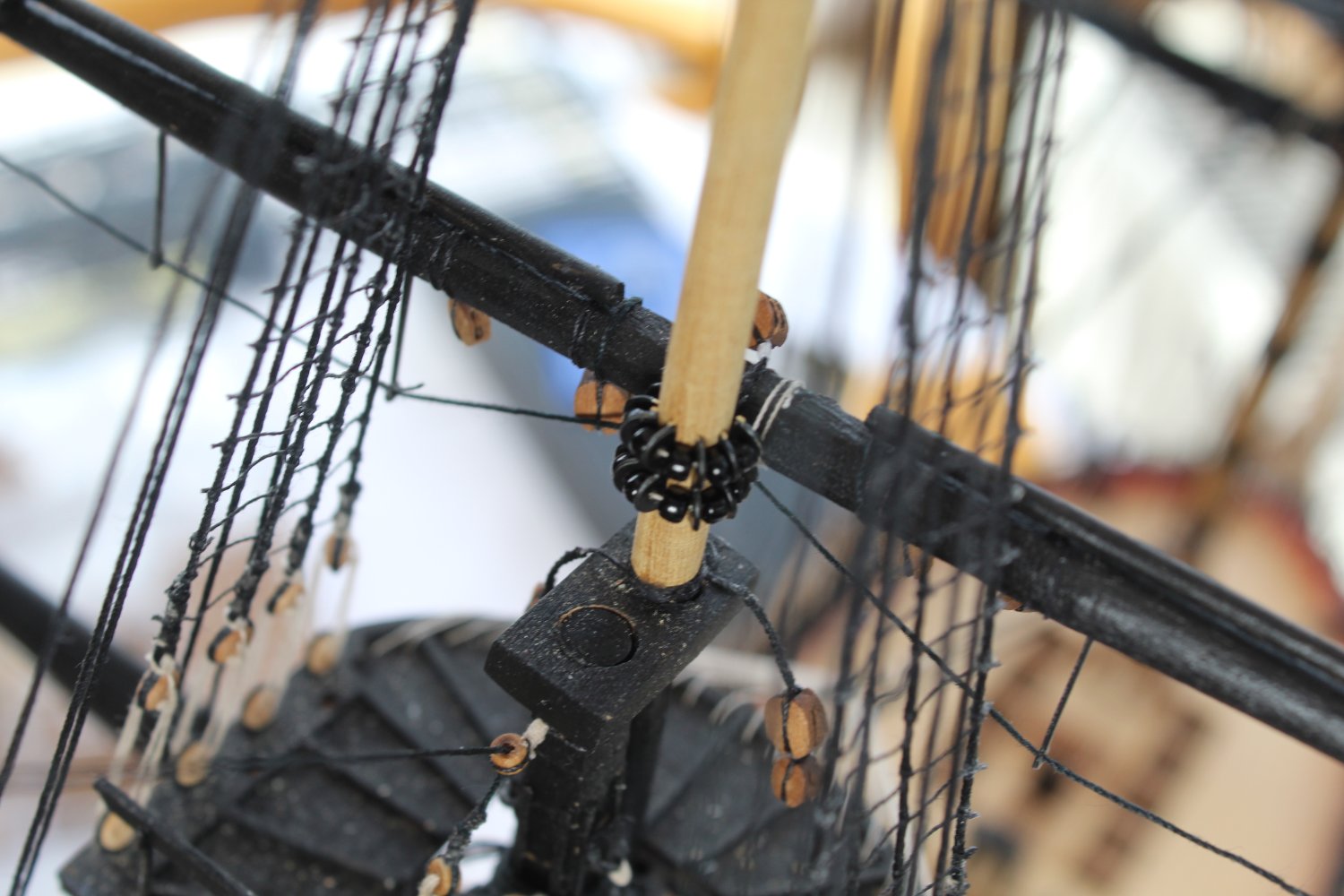
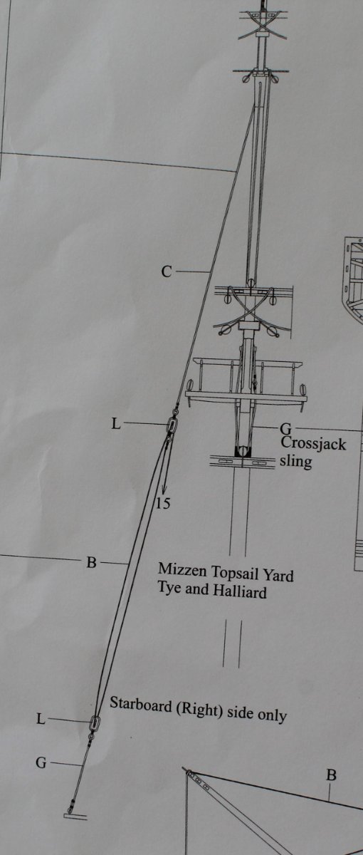
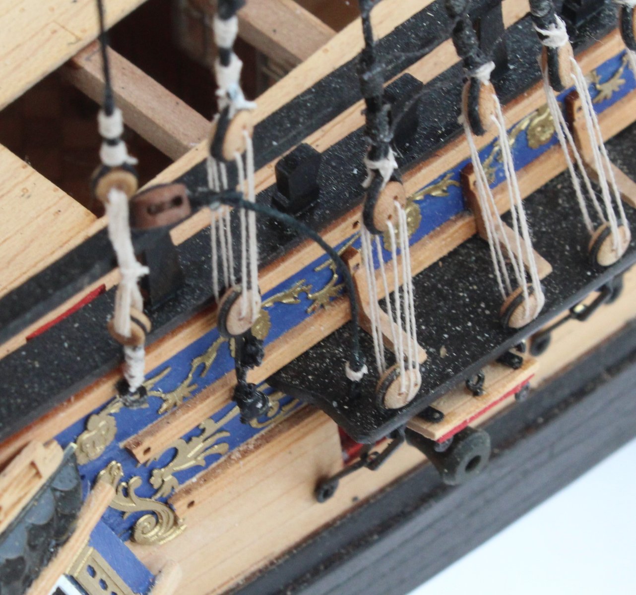
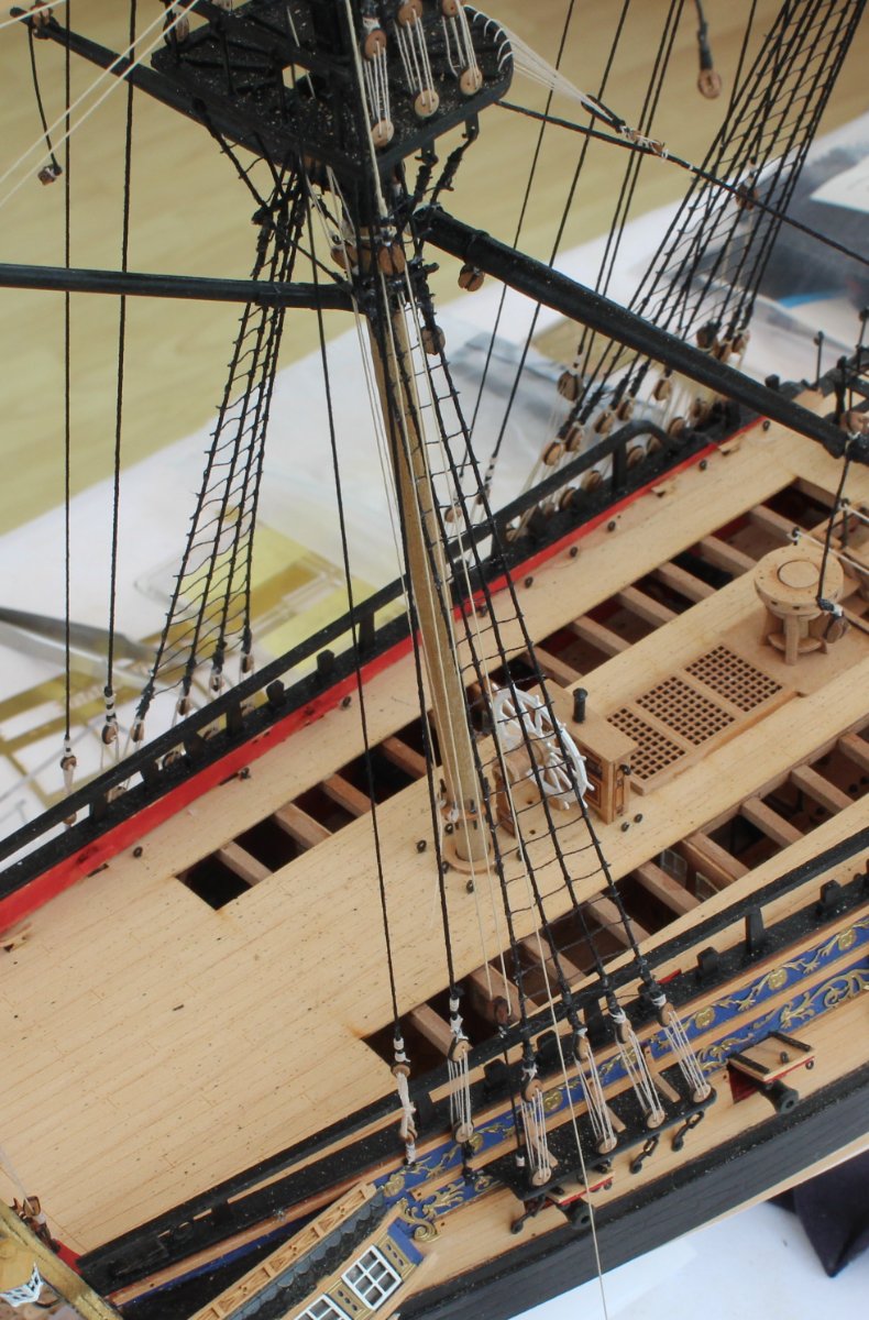
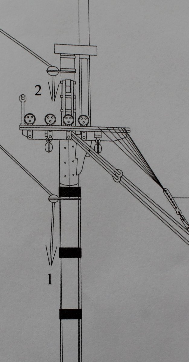
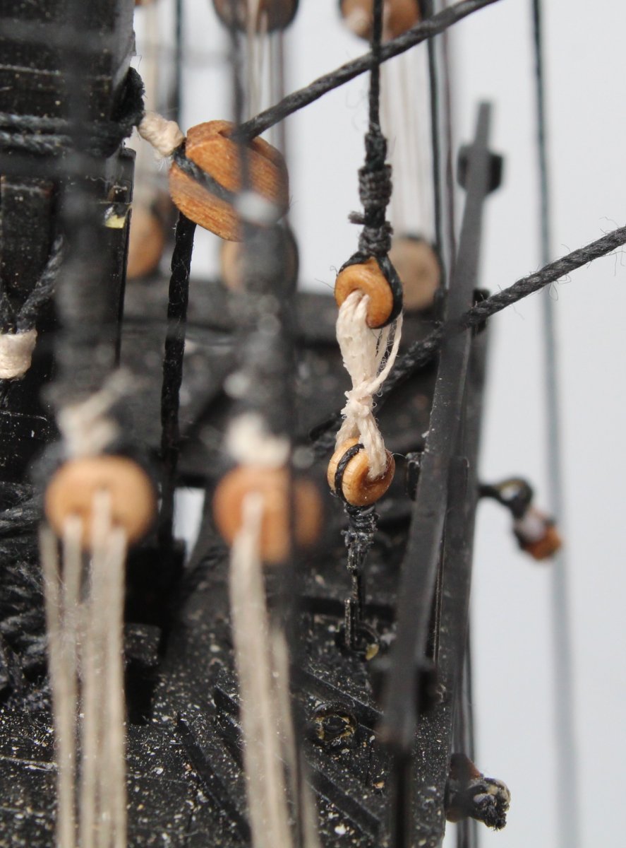
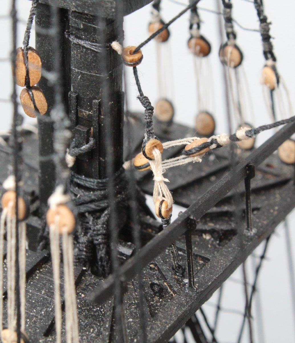
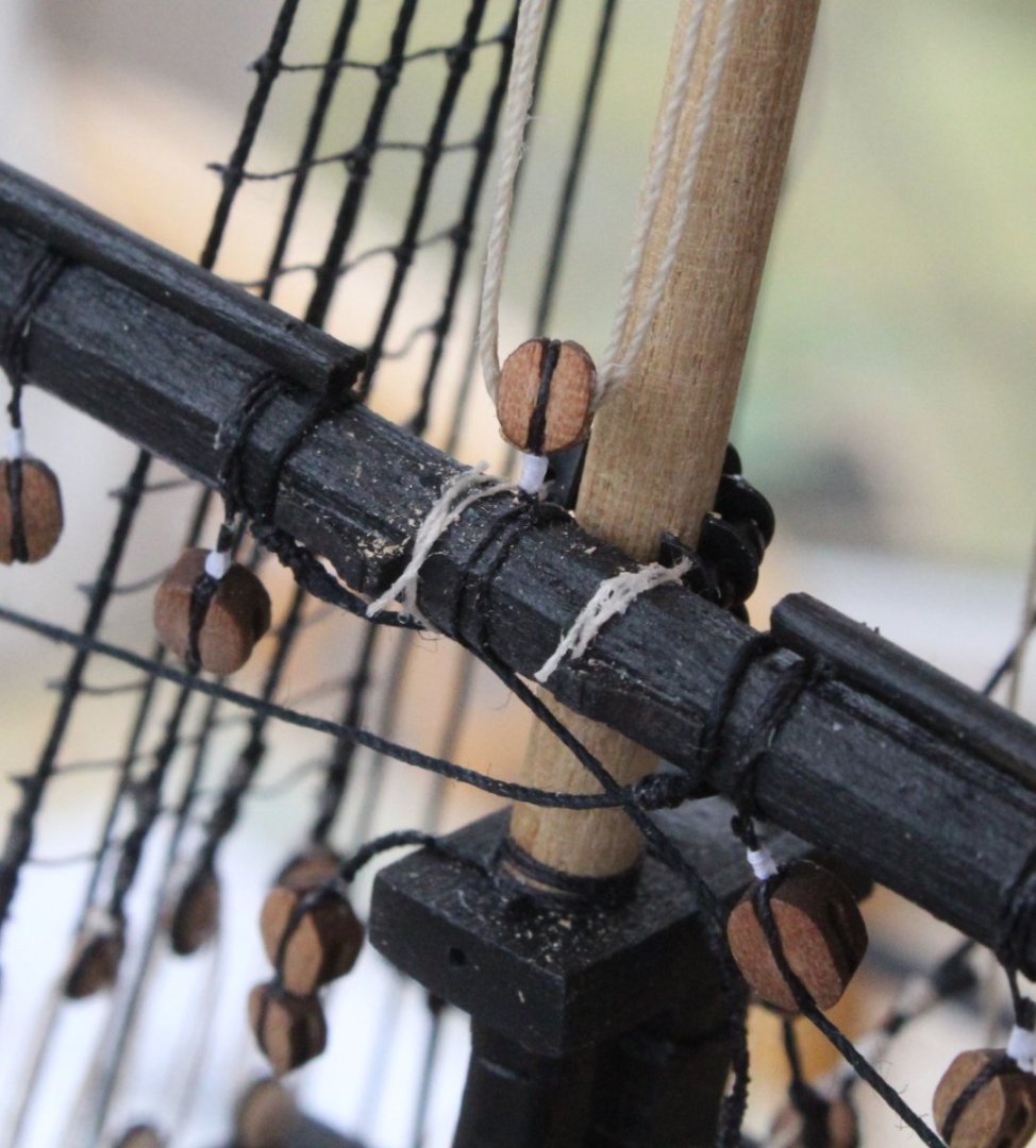
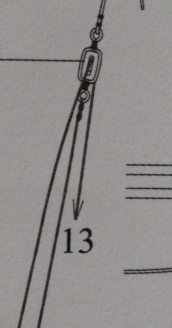
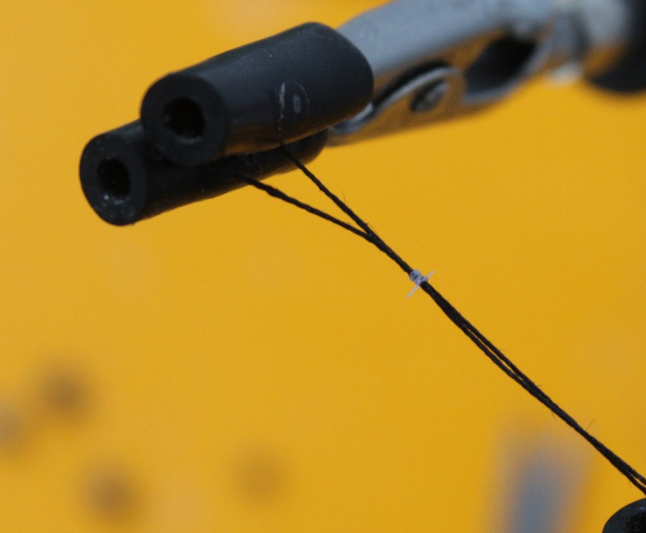
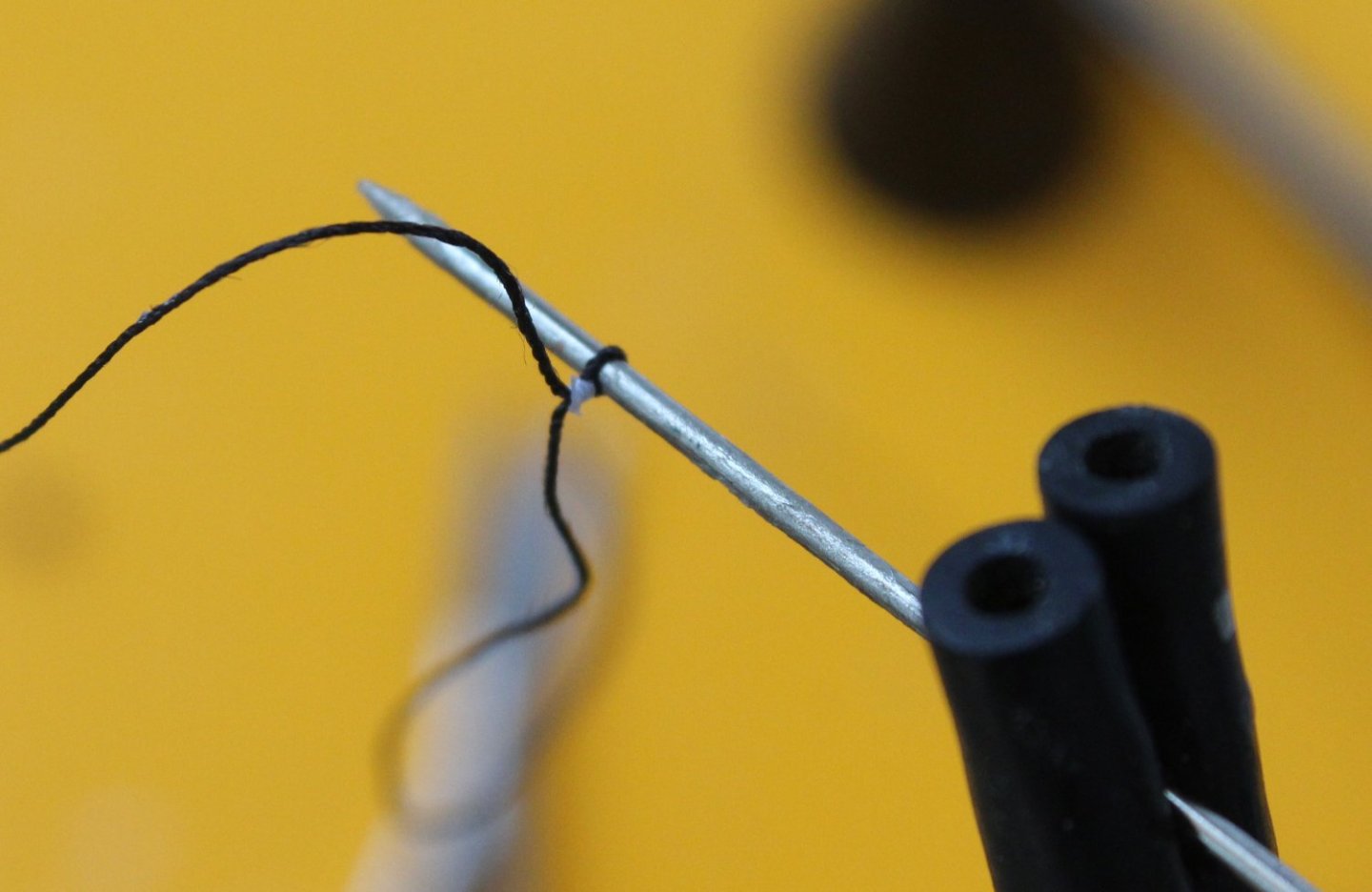
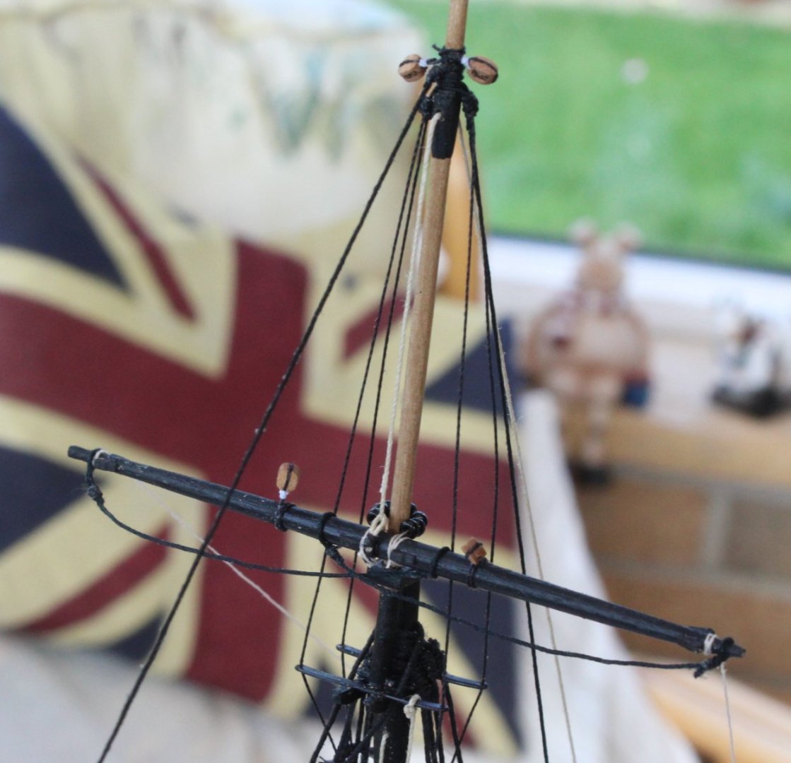
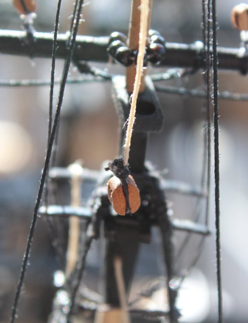
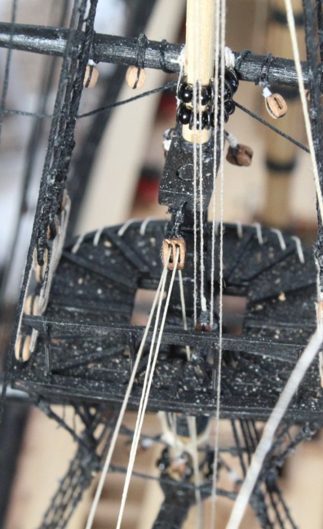
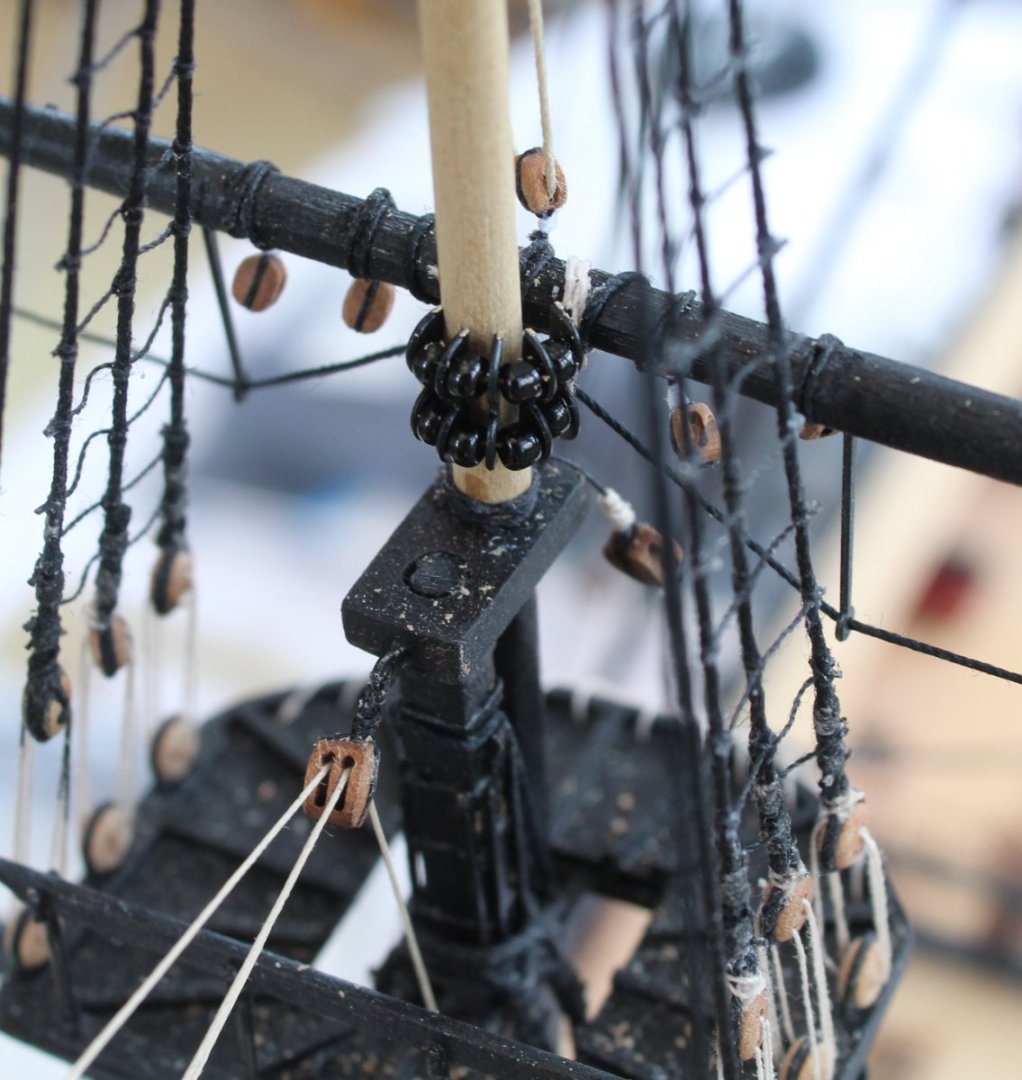
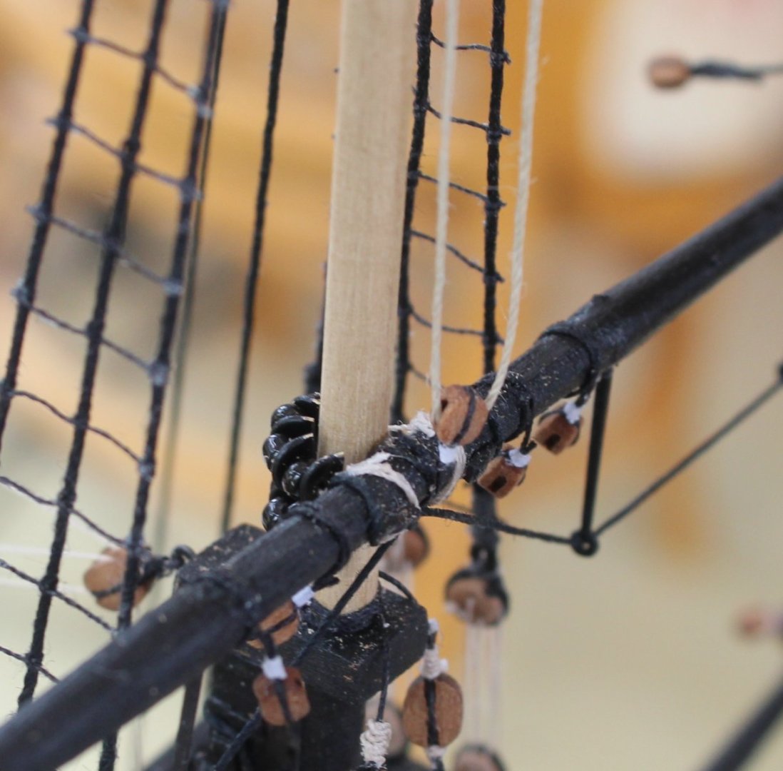
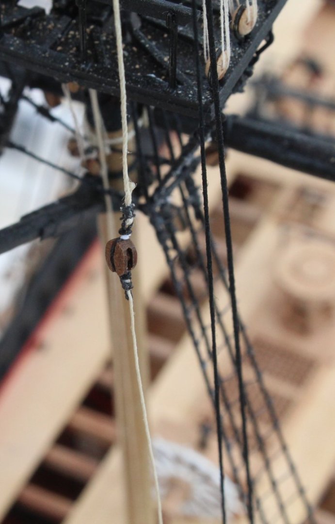
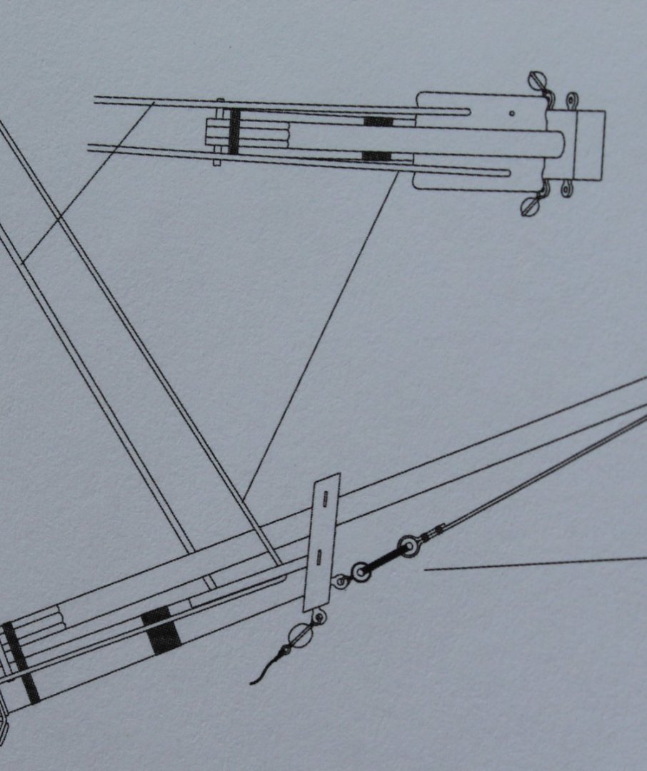
Mizzen Topyard I really enjoyed my cruise up and back down the Seine but now I am home my attention returns back to completing the Sphinx. The next task was to start securing the top and topgallant yards to their respective masts. Over the last couple of days, I have been working on the mizzen topyard which is secured to the top mast using parral beads and ribs. It was a bit fiddly to add the parral beads and rib arrangement but thankfully I was able to complete the task without any mishaps. With the topyard secured to the mizzen topmast I then looked at the tye and hilliard rigging requirement. As can be seen in the plan sheet the rigging (0.5mm natural thread) starts from the topgallant crosstrees. The thread is then passed though the central 3mm single block on the topyard. The thread is then passed through a hole in the topmast before it is belayed via a two 4mm single block configuration. One block is secured to the channel via an eyebolt the other block is seized to the end of the 0.5mm natural thread. The rigging between the two 4mm blocks is then belayed to a cleat fixed to the back of the rear starboard mizzen shroud. With the 0.5mm natural thread tied to the crosstree I was able to feed the thread through the central 3mm block, as can be seen below. Once the thread had been passed through the topmast hole a 4mm single block was seized to the free end. When adding the seizing a thimble was added to the block so a length of 0.25mm natual thread could be added, as can be seen in the photo below. A second 4mm single block was seized to a short length of black thread, complete with an eyebolt. The completed arrangement was then added to the mizzen starboard side channel as shown below. The natural thread was then rigged between the two 4mm single blocks. As can be seen in the final photo below the free end is now ready to be belayed to the shroud cleat. I still need to add the cleat to the shroud line.


- 476 replies
-
- 7
-
-
- sphinx
- vanguard models
- (and 1 more)
-
Many thanks for your kind words Tim, they are very much appreciated. I like to detail what I am doing. They might not be the best or correct methods but they seem to work for me.
- 476 replies
-
- 1
-
-
- sphinx
- vanguard models
- (and 1 more)
-
I can't take credit for the footrope shaping method but it does work really well so I'm pleased it will help others.
- 476 replies
-
- 2
-
-
- sphinx
- vanguard models
- (and 1 more)
-
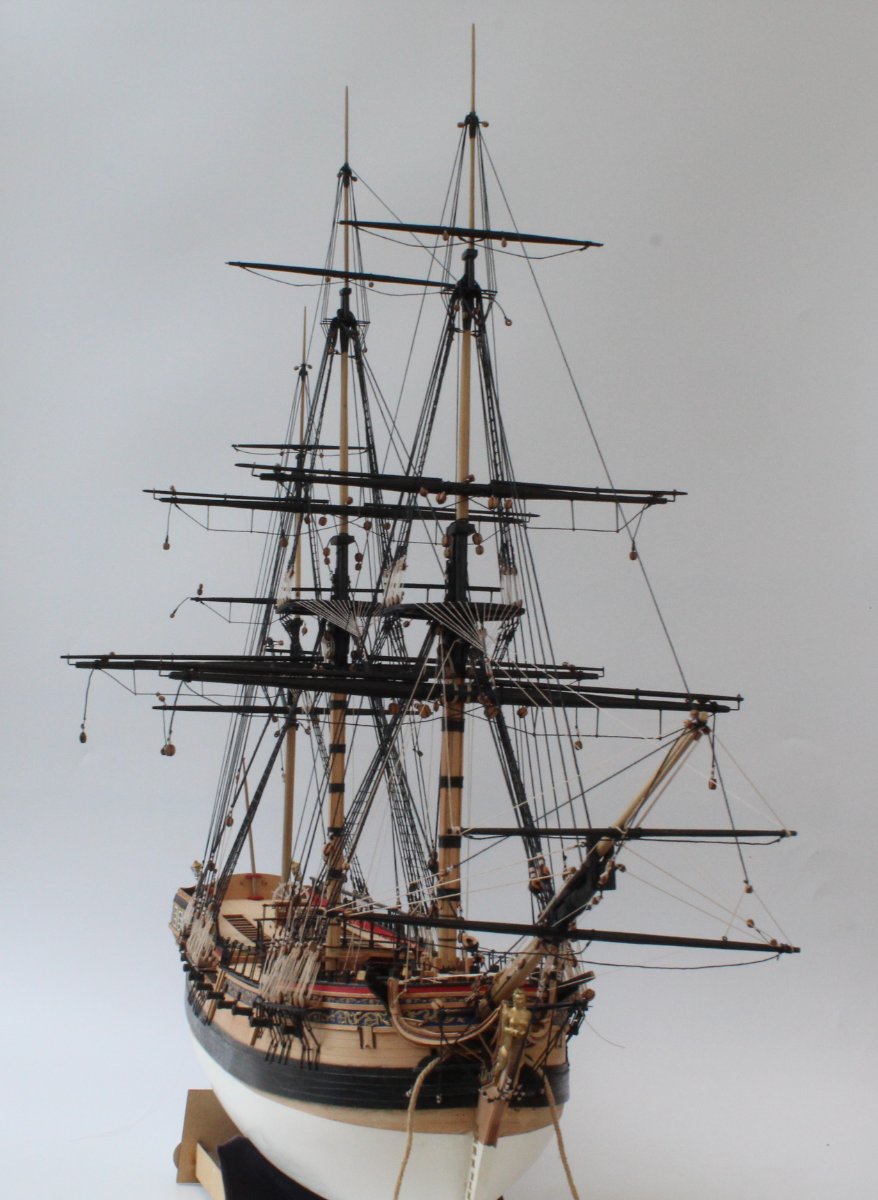
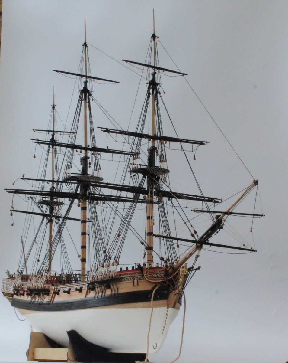
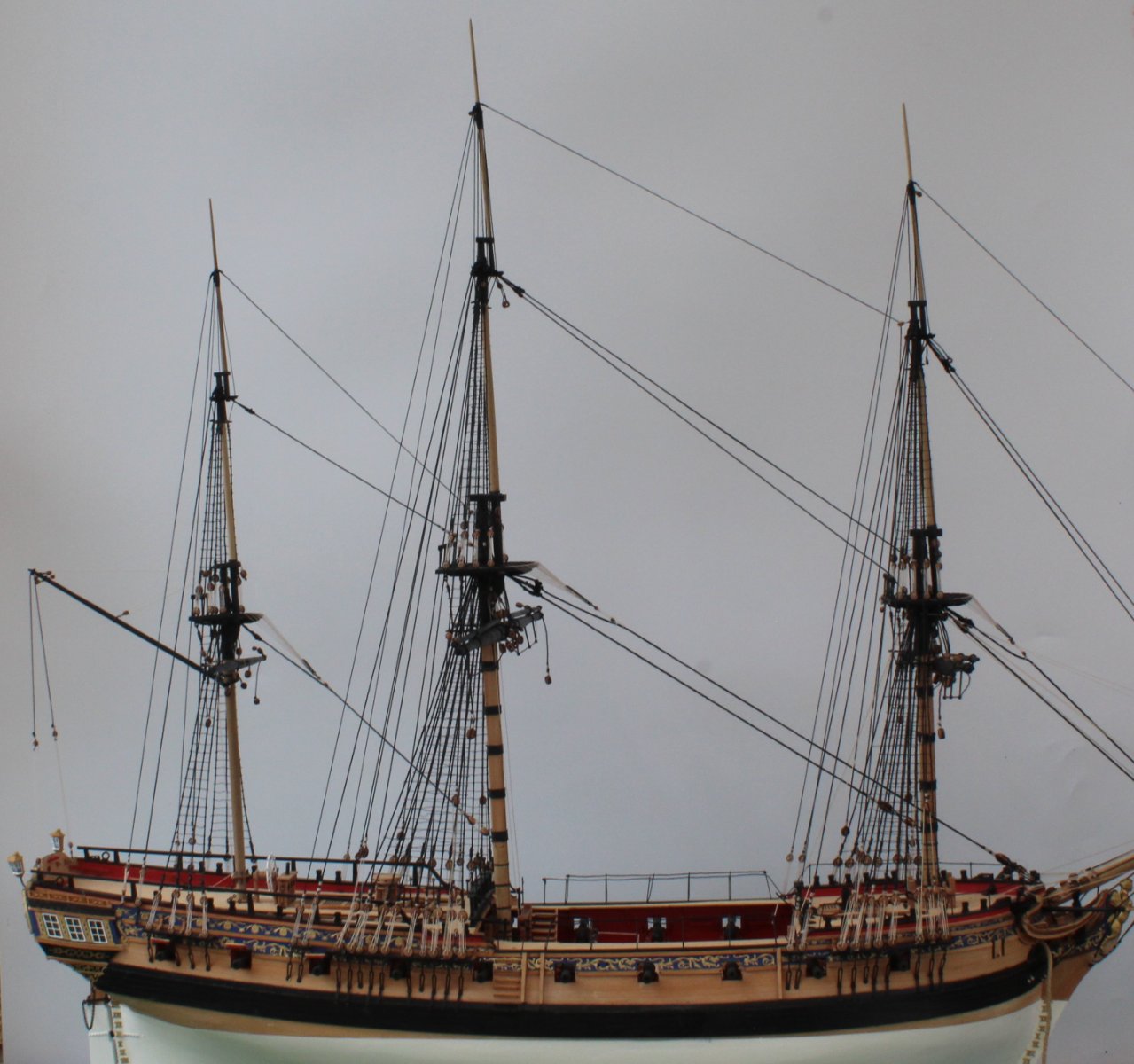
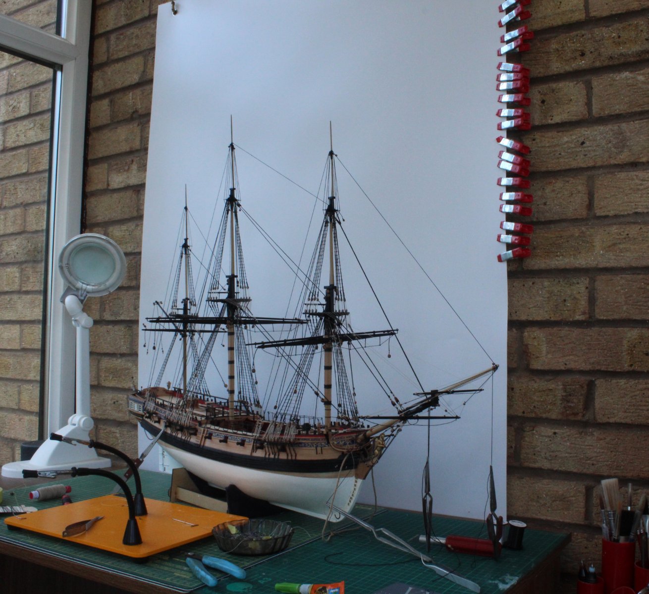
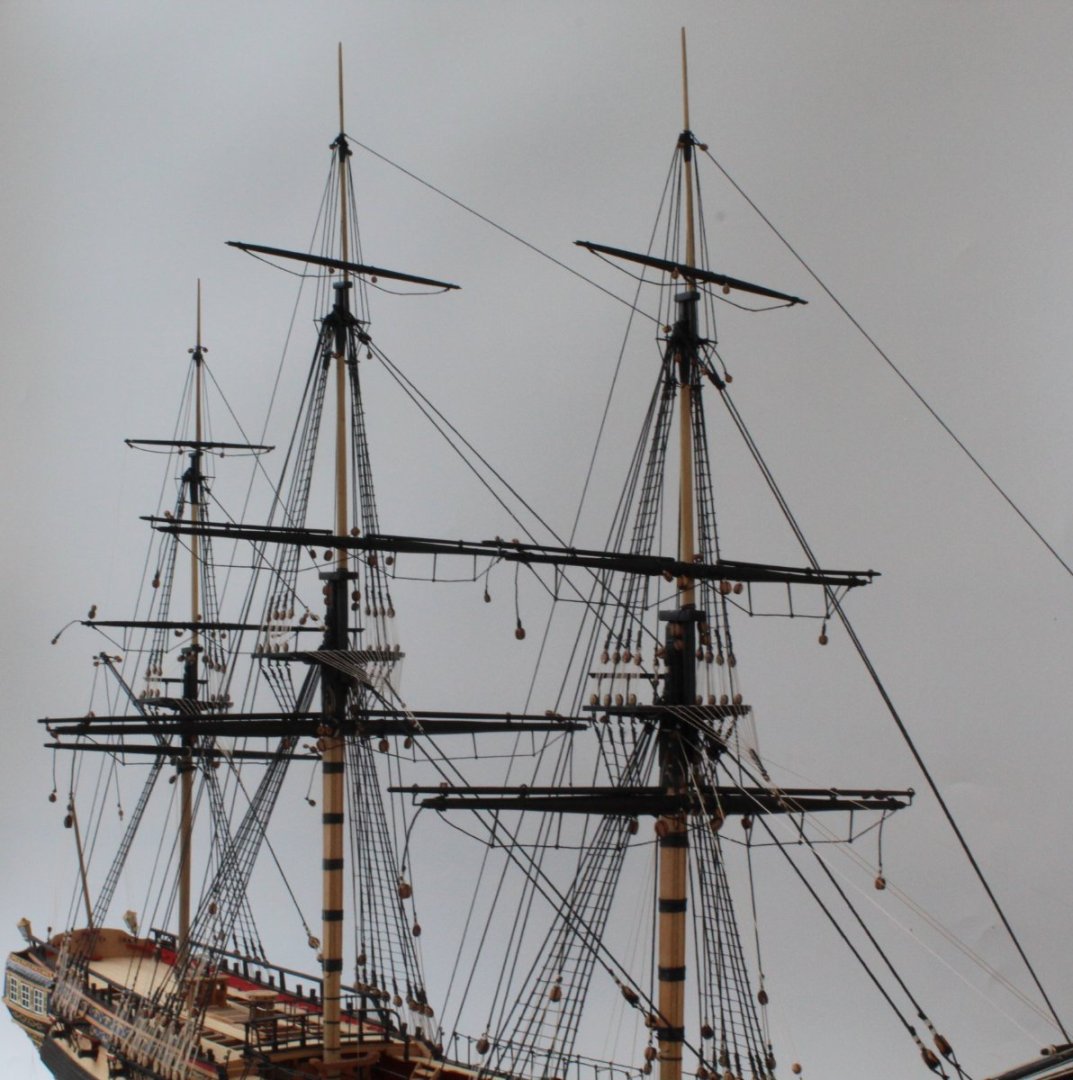
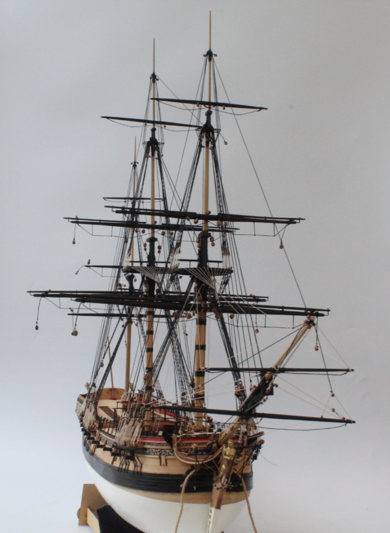
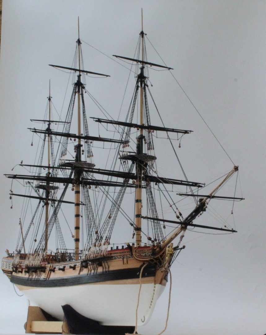
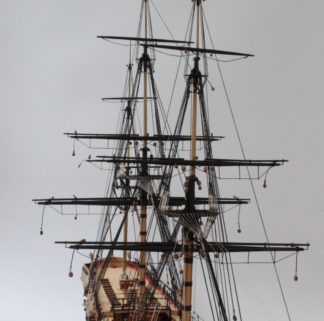
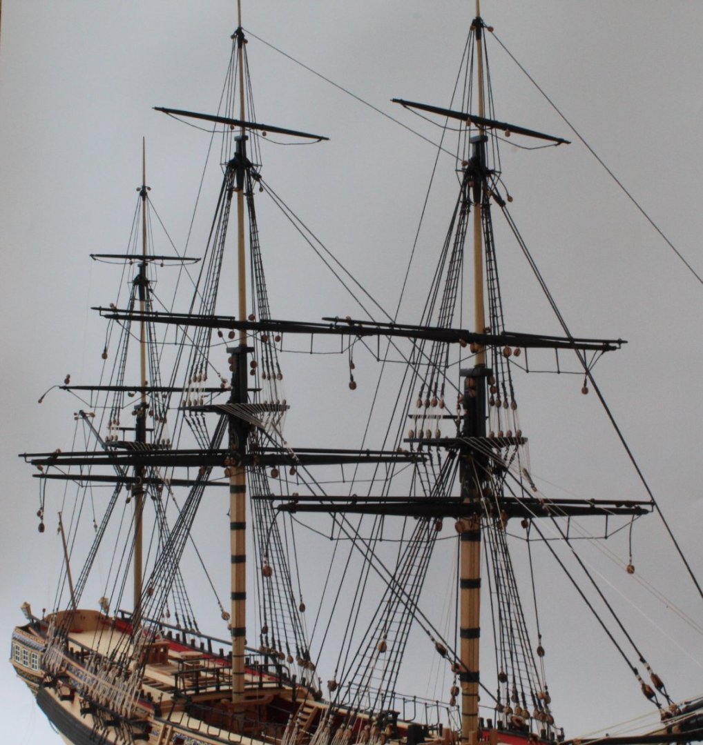
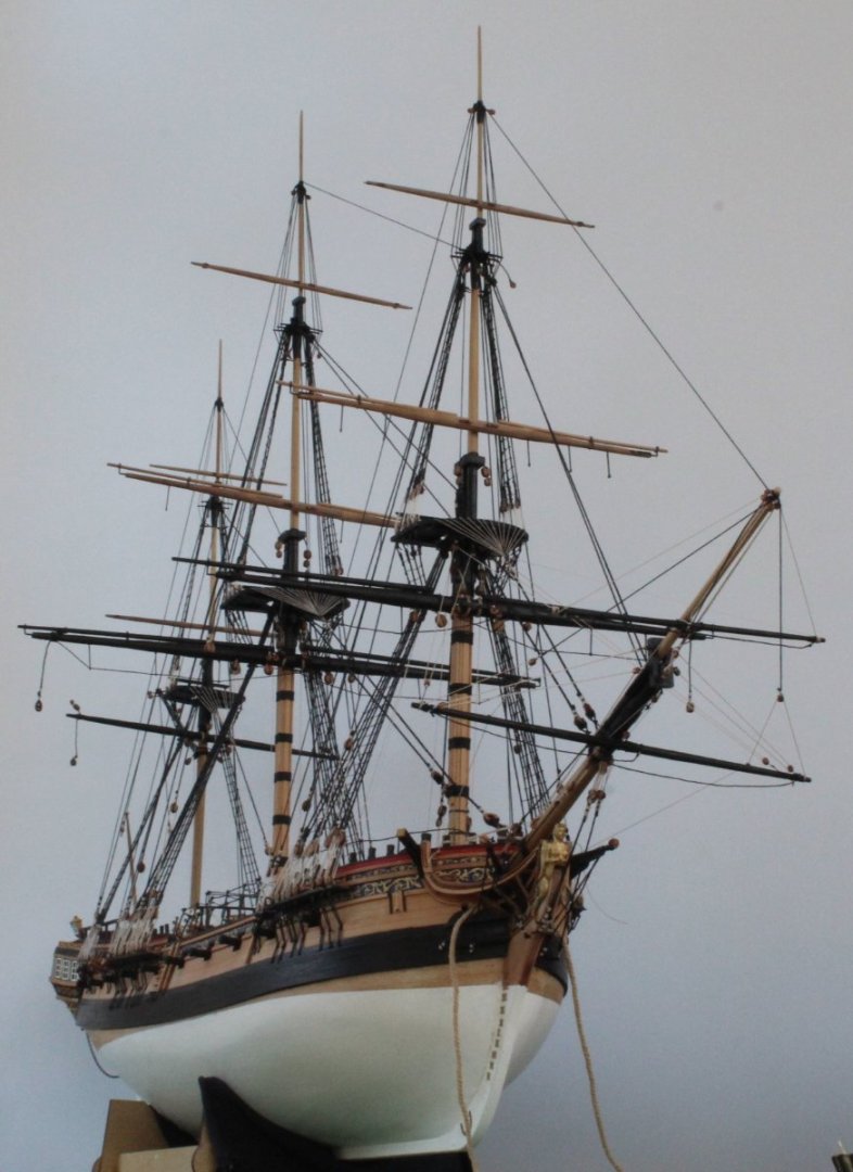
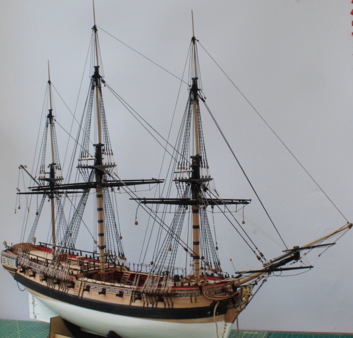
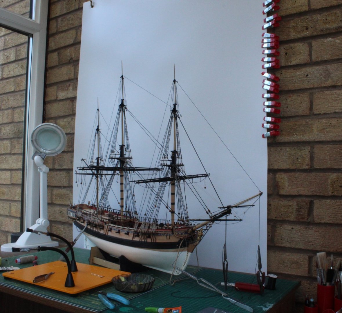
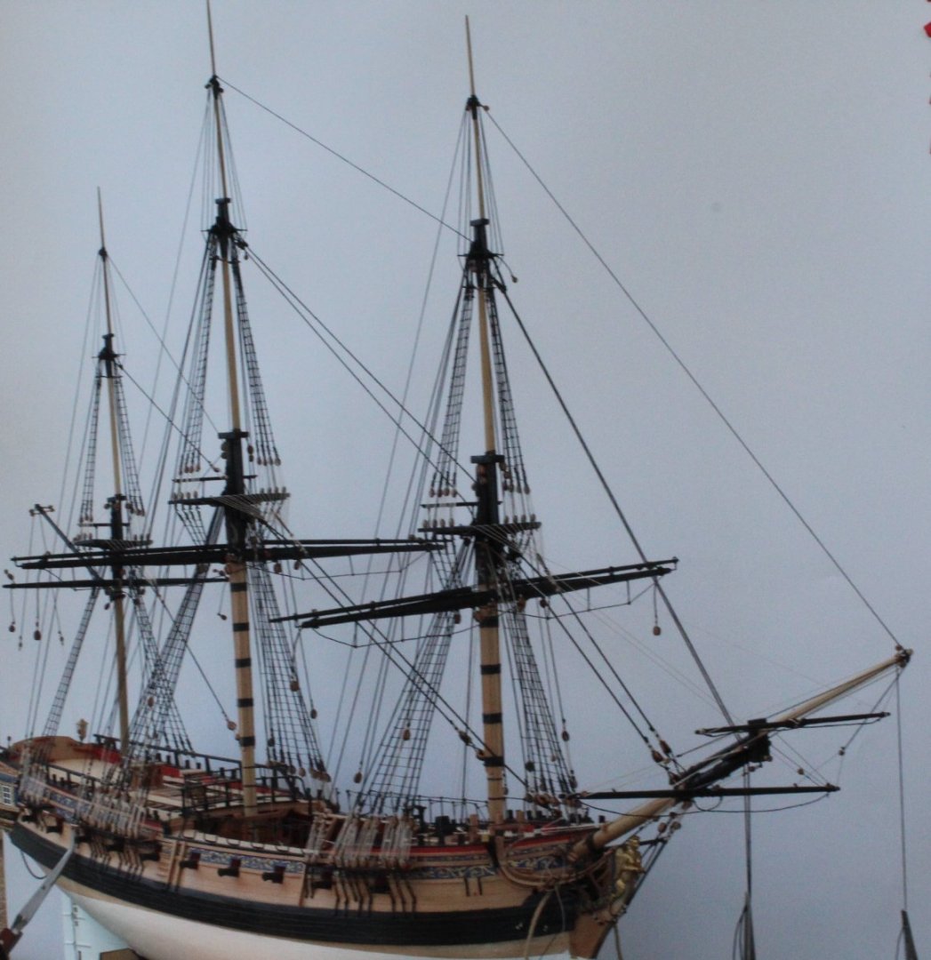
Yard Work Completed Another major milestone on this build project has now been completed as I have now finished all the work related to the manufacture of the top and topgallant yards. I am pleased I managed to complete this activity before leaving for an 8 day river cruise on the Seine tomorrow morning. This means on my return back to dear "old blighty" next week I am just left with the rigging all the yards. Assuming I do not encounter any major snags I hope to be able to complete the yard rigging by the end of September. There is then just the small matter of building the 3 small boats. As I bid you au revior here is a nice selection of photo's of the Sphinx as she will be left for the next 8 days.
- 476 replies
-
- 7
-
-
- sphinx
- vanguard models
- (and 1 more)
-
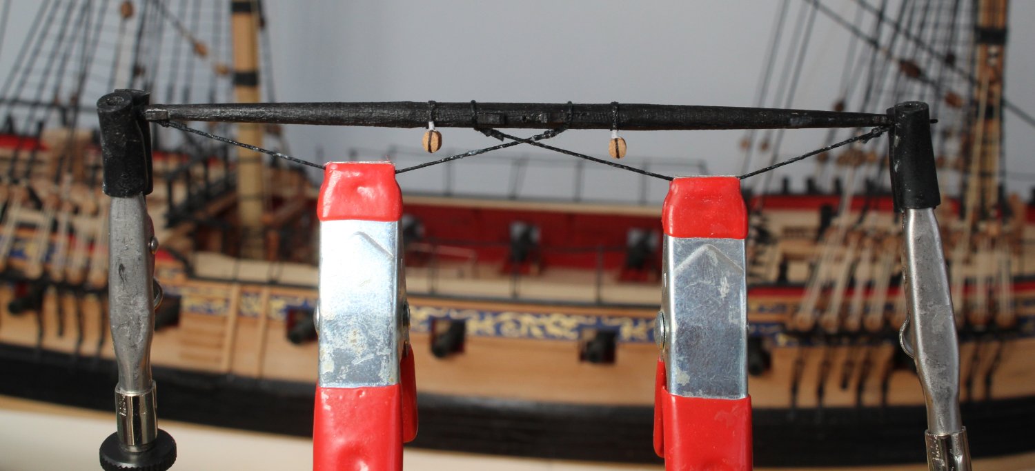
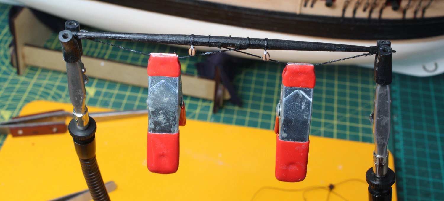
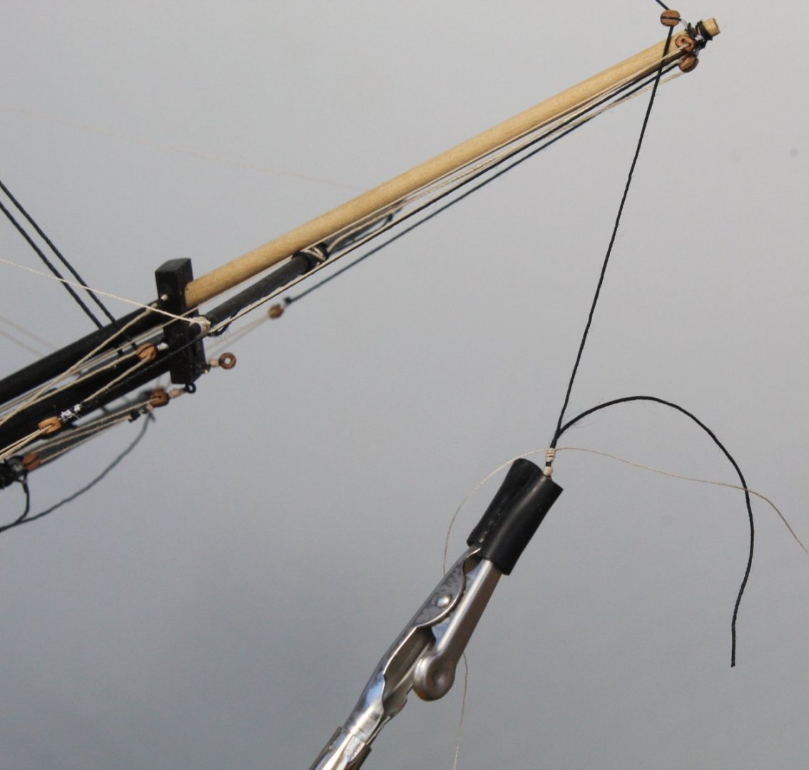
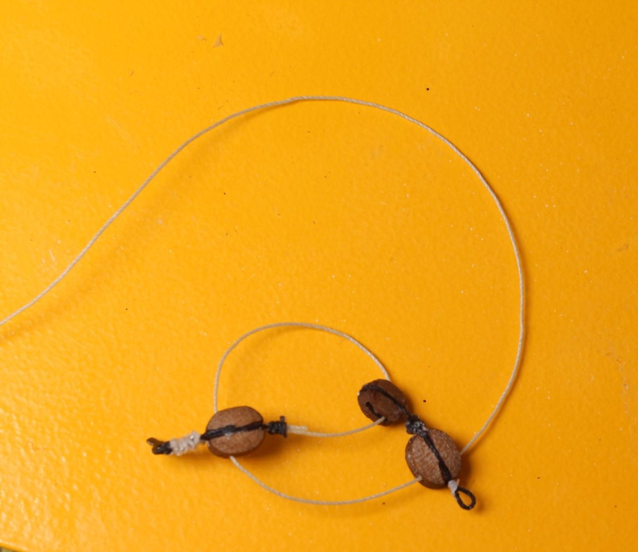
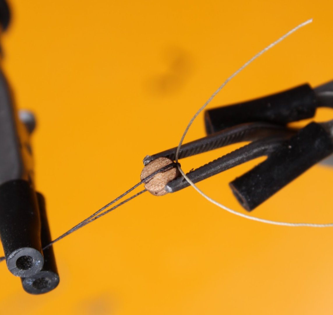
Fore Topgallant Yard I thought I show how I shape the yard footrope's with today's post. When the footrope is added to the the yard I adjust the position of the footrope seizing as necessary to get the require shape. It take a bit of trial and error to get right but is not a very long process. Once I am happy with the footrope the yard is held in place using the quad hands. I then use a clamp on each of the footropes to create the required shape, as can be seen in the photo below. With the clamps in place a diluted solution of pcv glue is brushed on the footropes which are then left to dry. The next picture shows more of the quads hands holding the yard in place. I have just one more yard to complete (Fore Topyard) which I hope to do later on today.


- 476 replies
-
- 3
-
-
- sphinx
- vanguard models
- (and 1 more)
-
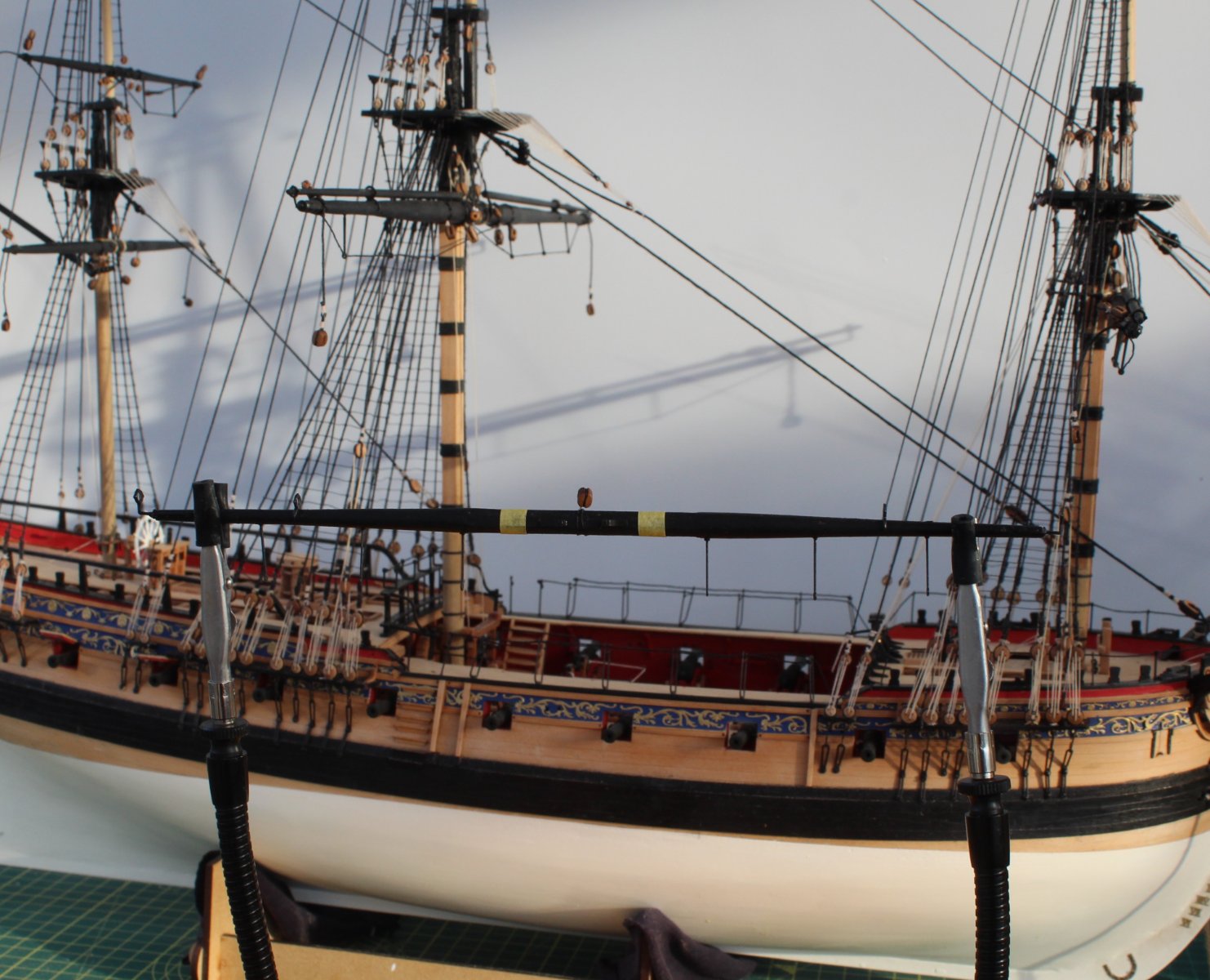
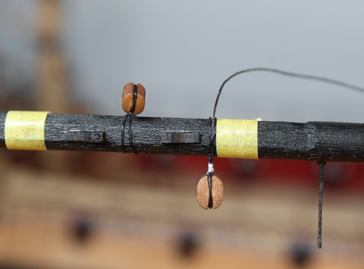
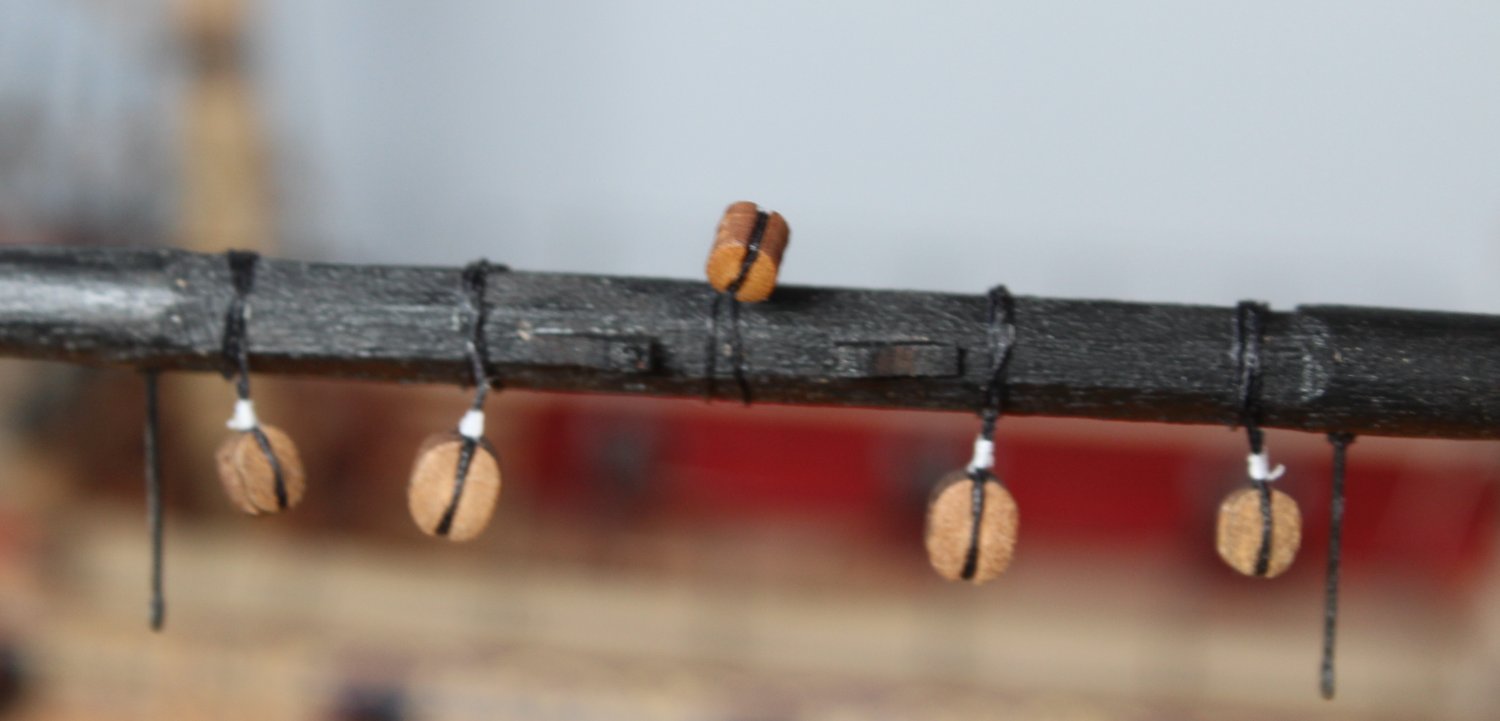
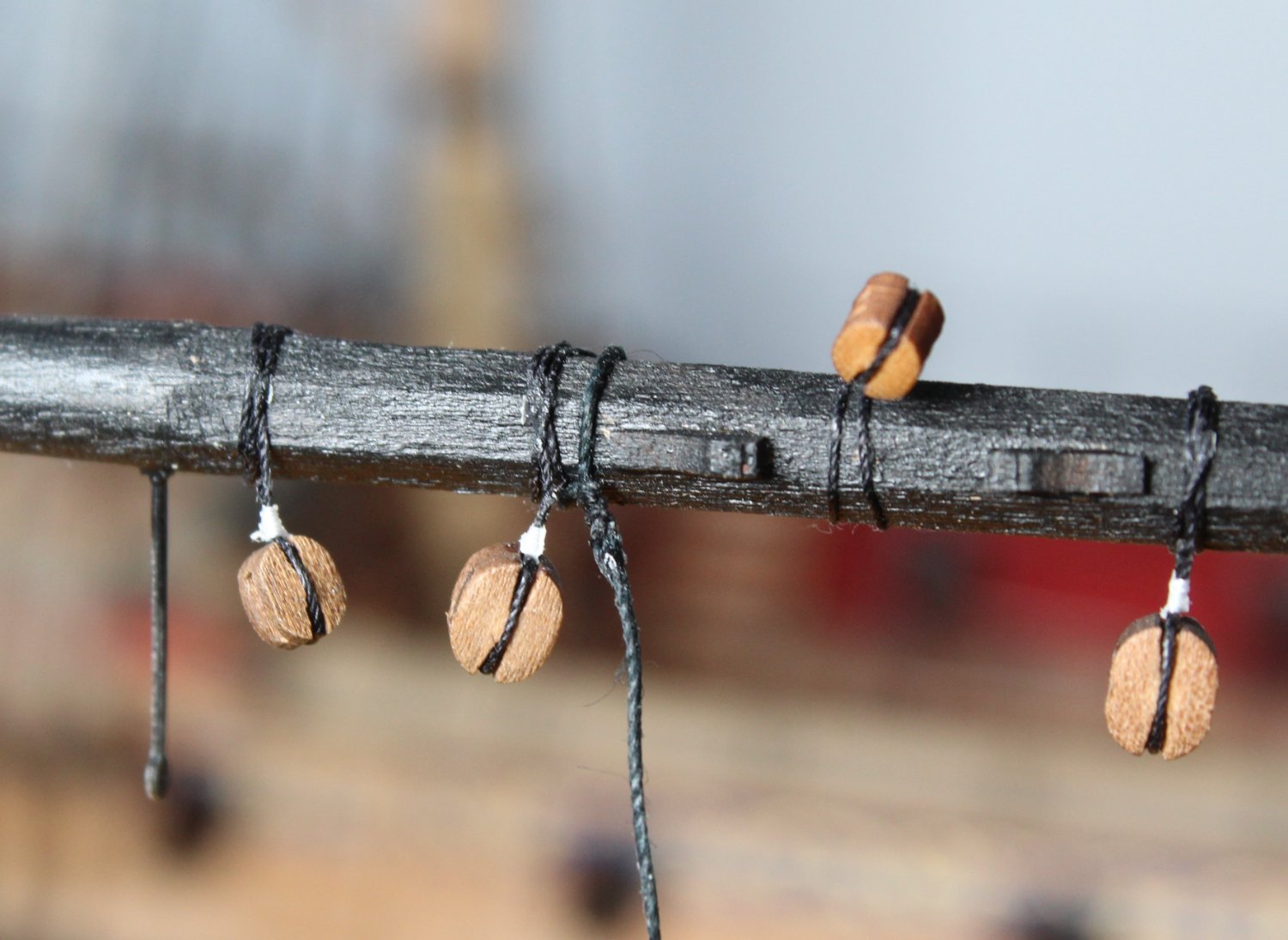
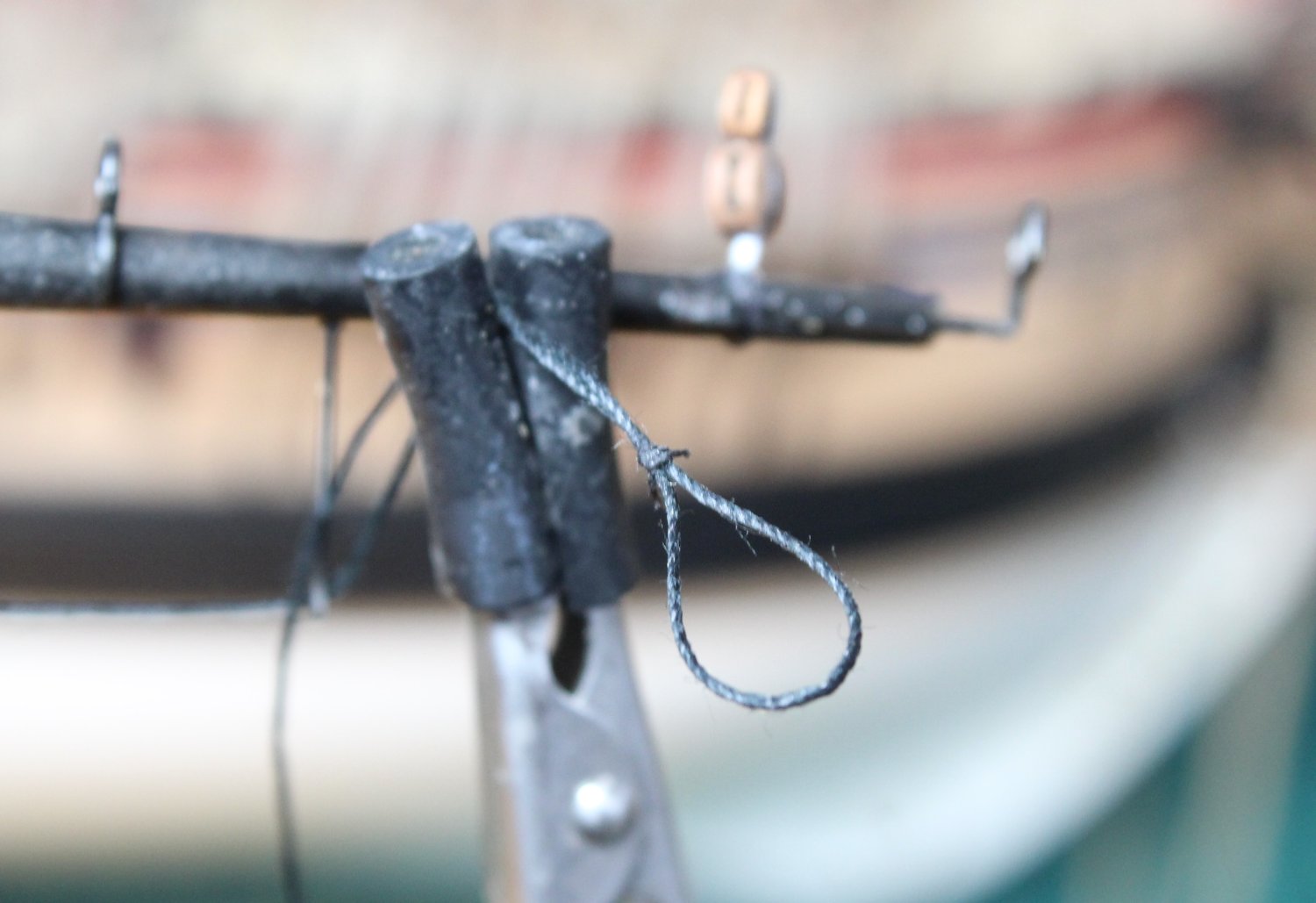
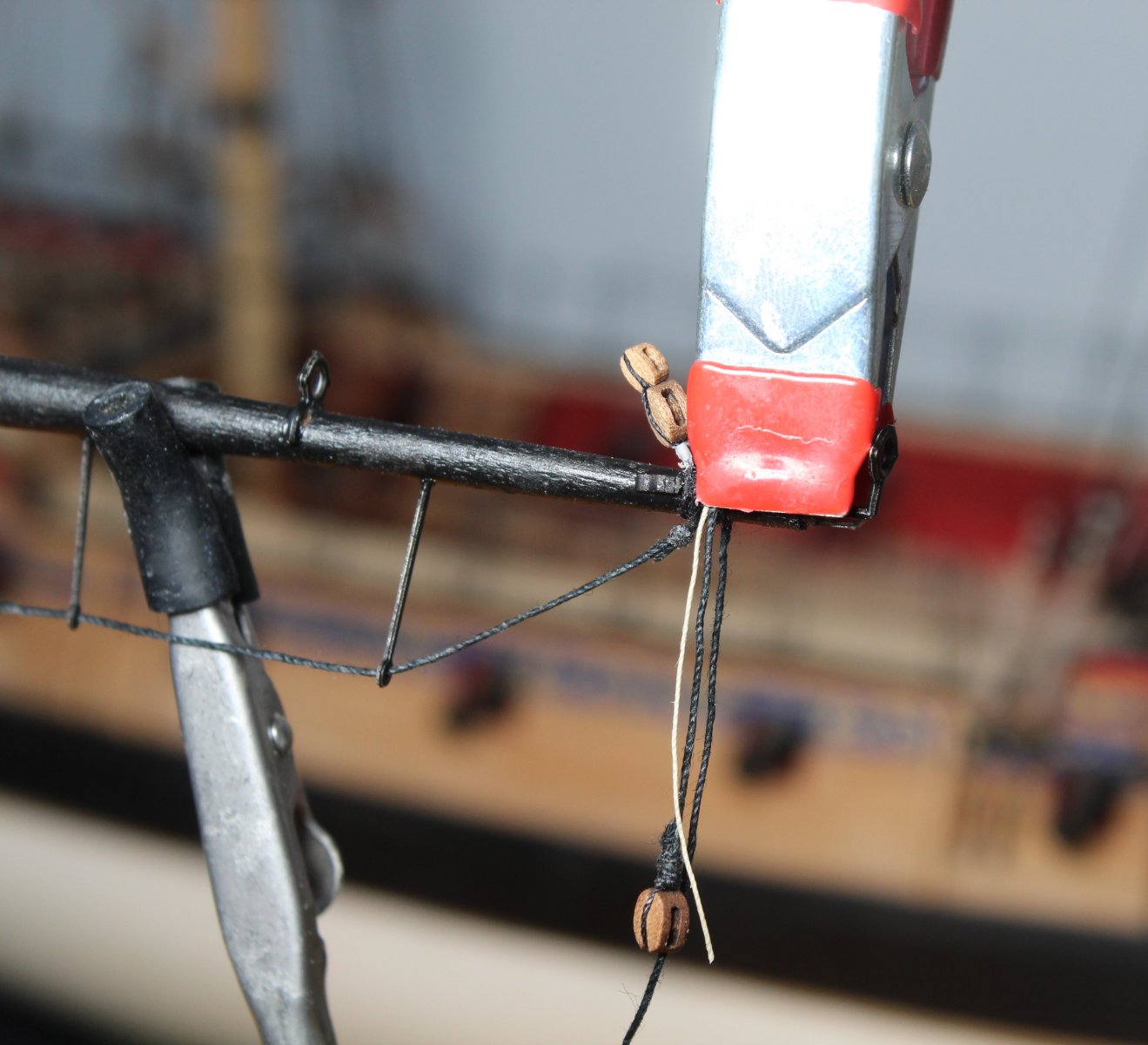
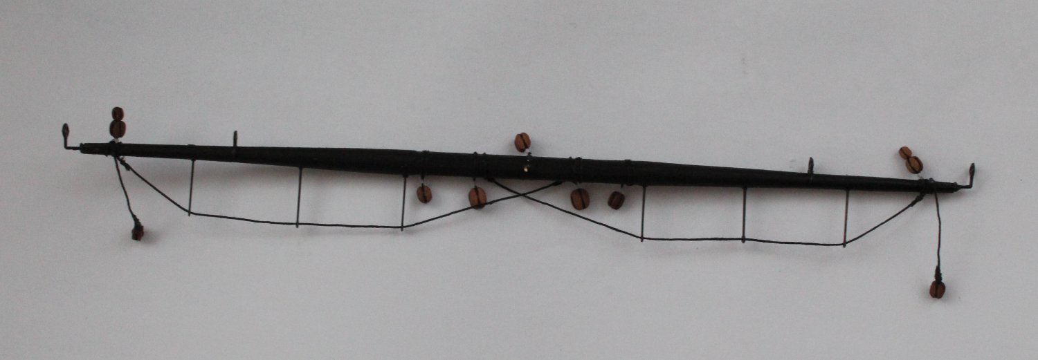
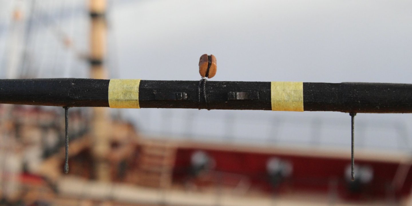
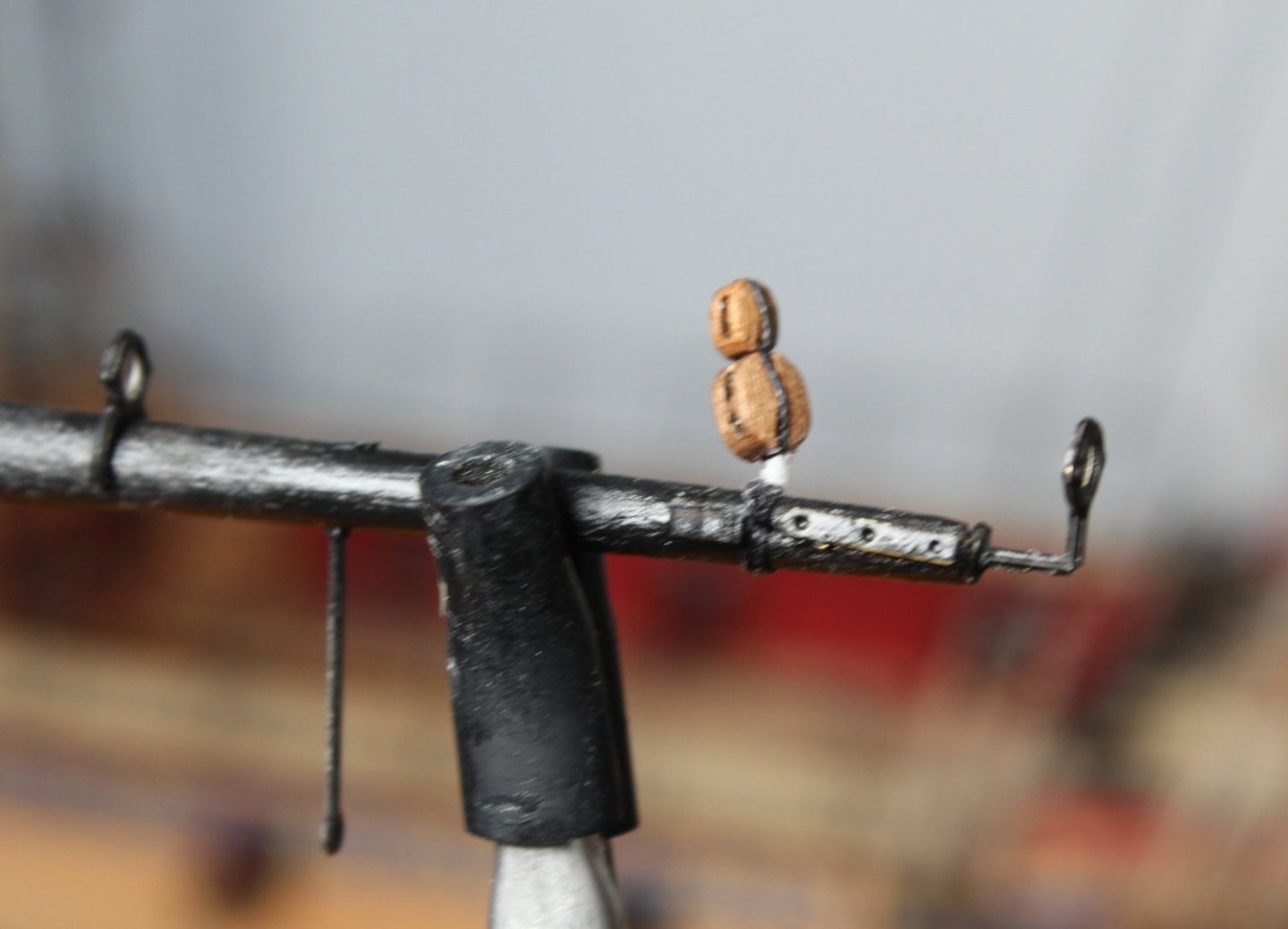
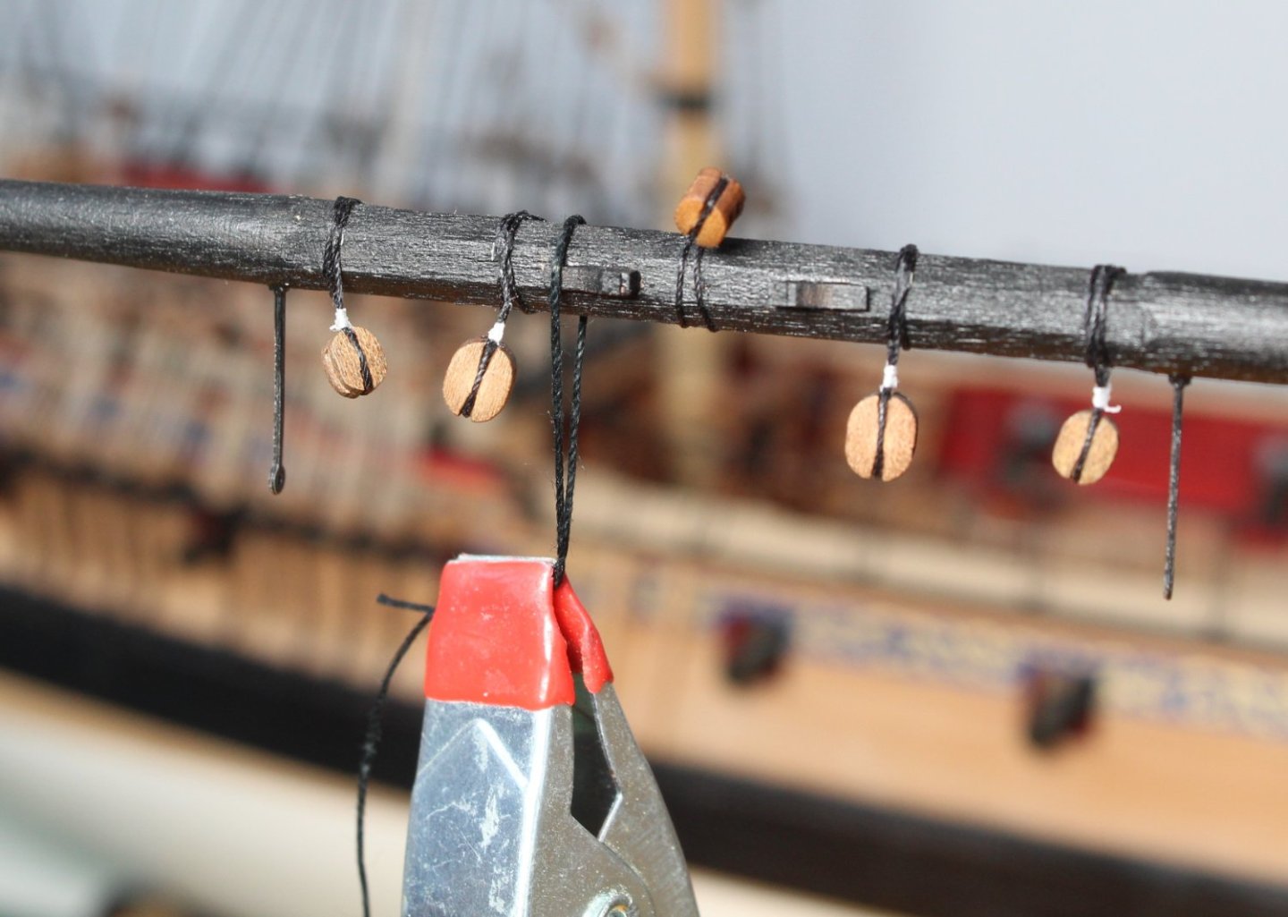
Main Topyard Fixtures and Fittings I was able to spend a couple of hours in the shipyard today and completed both the main topgallant and main top yards. I thought I would detail the method I used to add the fixtures and fittings to the main topyard. With the yard held in the place using the quads hands, as shown in the photo below, the central double 4mm lift block was added, secured to the yard using a clove hitch knot. I then added some tape to mark the position of the 2 off 5mm single blocks on the yard, as can shown in the photo below Using the tape as a guide the first 5mm block was added to the yard, secured using a clove hitch knot, as shown below With both 5mm blocks added I repeated the taping process and added the 2 off 4mm single blocks. The work on the central part of the yard is now complete as shown in the photo below. Next I added the 2 off double block assemblies to each end of the yard. Before adding the two brace blocks I have found it is better to add the footrope stirrup rigging. To do this I started by wrapping a length of 0.5mm black thread around the yard, next to the one of the central cleats. I used a clamp to hold the thread in place as shown below. With the thread held in place it was an easy task to add the seizing. The loop was then tighten and the excess thread trimmed. I then added the second thread to the other central cleat using the same method. The two threads were then fed through the yard footrope stirrups as shown in the next photo Next I created the loops in the other end of the footrope stirrup threads. To do this one end of the yard was removed from the quad hands which then allowed me to seize the loops, as can be seen in the next photo The loop was then placed over the end of the yard and the position of the seizing adjusted, as required. Once I was happy with how the footrope stirrup rigging was looking I then moved to to adding the two brace block assemblies to each end of the yard. I used a template to set the length of these braces, as can shown in the photo below. The completed main topyard is shown in the photo below


- 476 replies
-
- 5
-
-
- sphinx
- vanguard models
- (and 1 more)
-
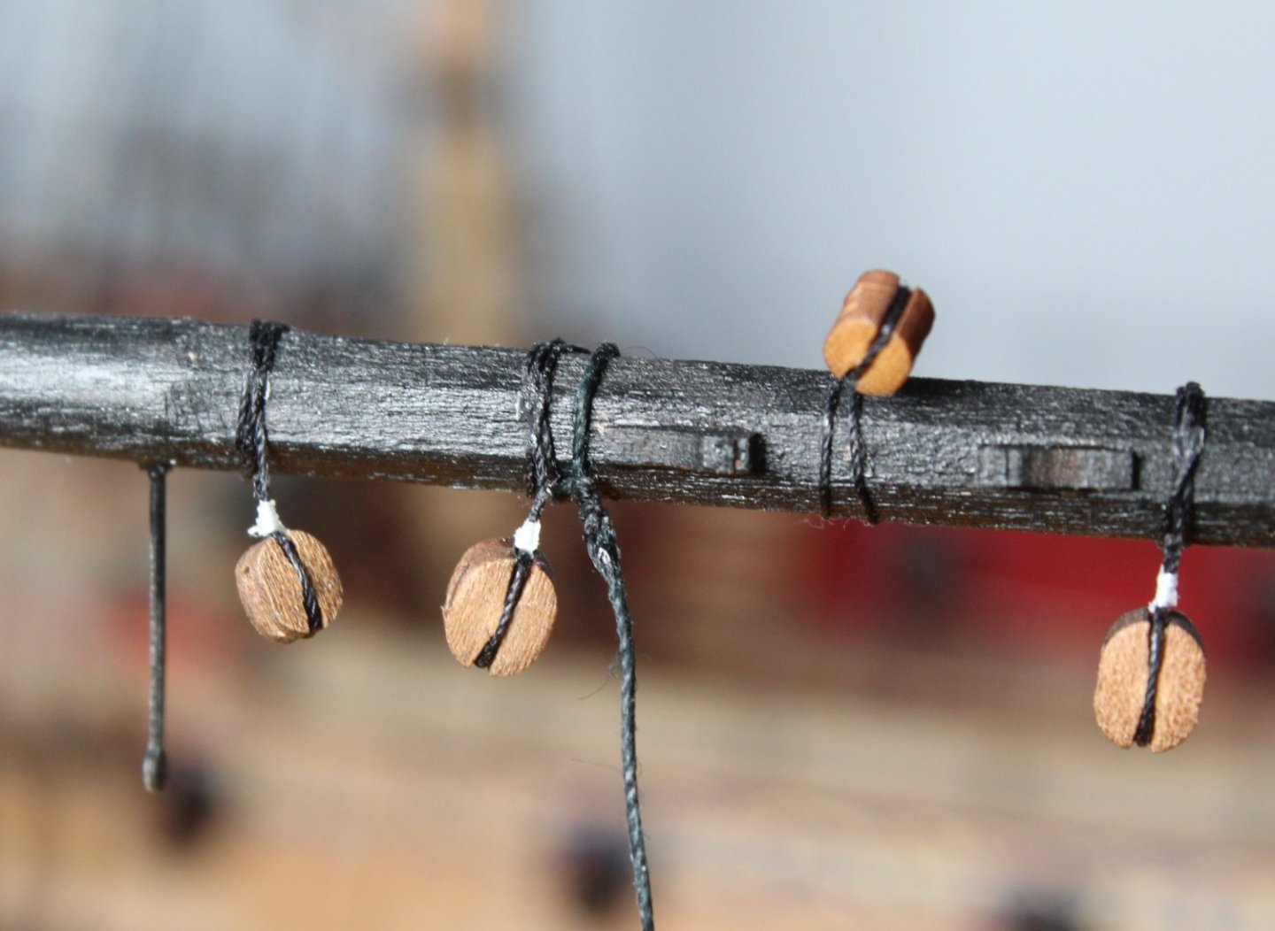
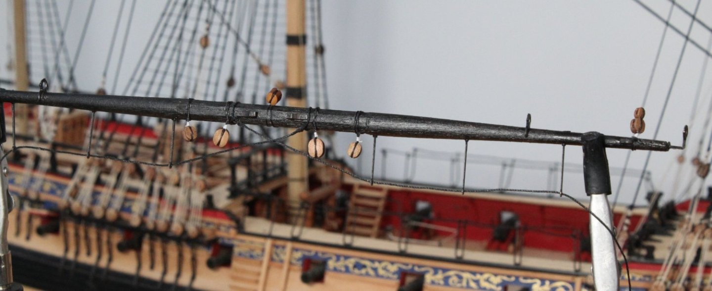
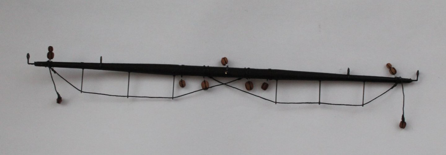
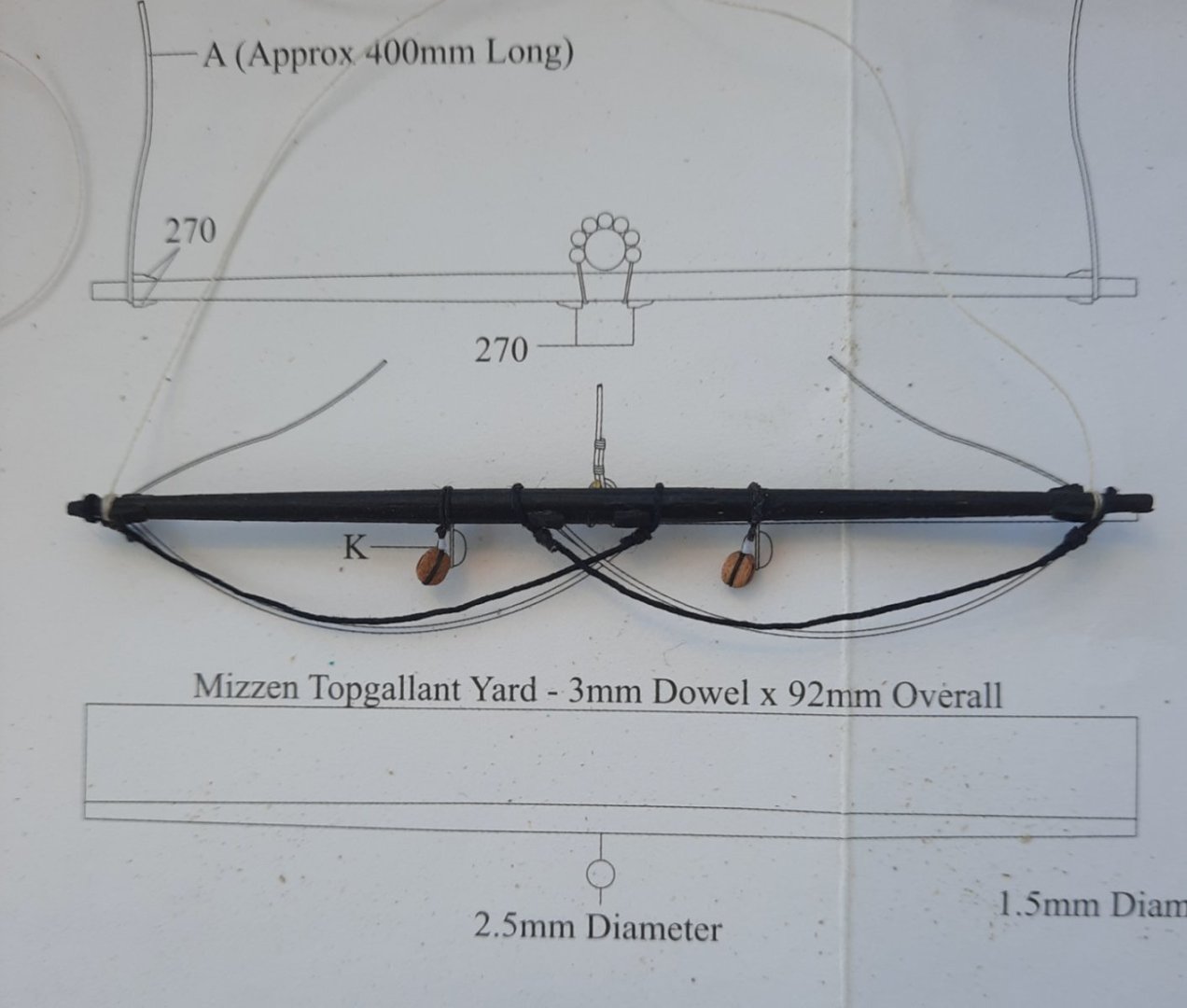
Mizzen Topgallant Yard I managed to sneak 30 mins in the shipyard this morning and completed all work on the mizzen topgallant yard. After fitting the yard fixtures and fittings I held the yard in quadhands and used a couple of clamps to shape the foot stirrup's. Once I was happy with the foot stirrup shaping I applied a coat of a diluted pva solution. Overall I think the end result passes muster.
- 476 replies
-
- 3
-
-
- sphinx
- vanguard models
- (and 1 more)
-
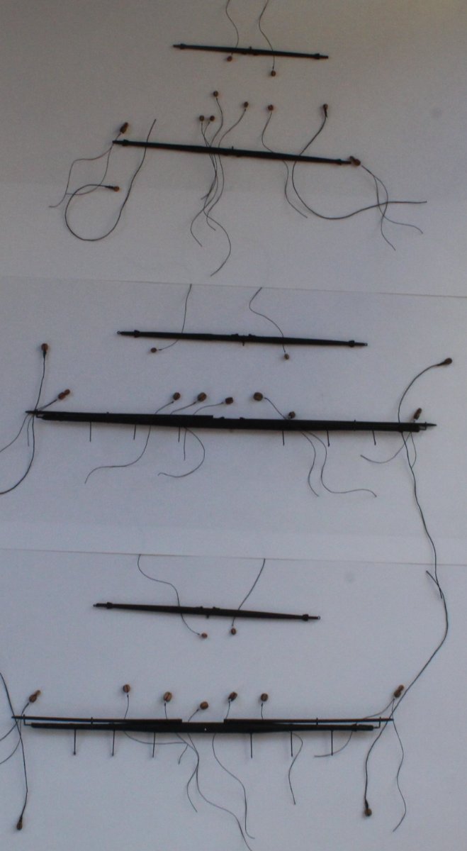
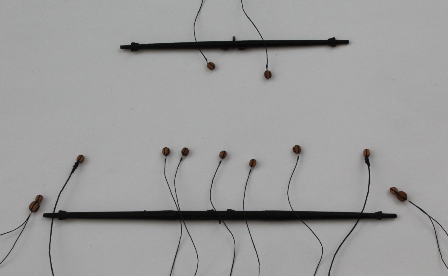
Top and Topgallant Yard Block Manufacture It has been a busy period over the last 2 days as I have been seizing a multitude of blocks for the various top and topgallant yards. I had to push on to complete the task before my holiday next week. I also realised I would have precious little time in the shipyard on Friday or Saturday as we are looking after three of our 4 grandsons. Thankfully the ship building gods were looking down on me and allowed me to work without any major mishaps or misadventures. I started with the Mizzen Top and Topgallant yards which have been painted black. There are only two 3mm single blocks required for the Mizzen Topgallant Yard. There are 11 blocks in total required for the Mizzen Top yard. As can be seen in the photo below the blocks have been seized and are ready to be secured to the yards. I am planning to secure each block to their respective yards using clove hitch knots. With the Mizzen block seizing completed I moved on to seizing the various blocks for the the main top and topgallant yards. There are only two 3mm single blocks required for the Main Topgallant Yard. There are a total of 11 blocks required for the main top yard. As can be seen in the photo below the yards have been painted black and all the blocks have been seized and are ready to be secured to their respective yards. I am planning to use a clove hitch knot to secure each of the blocks to the yards. I then moved on to seizing the various blocks for the the fore top and topgallant yards. There are only two 3mm single blocks required for the Fore Topgallant Yard. There are a total of 11 blocks required for the fore top yard. As can be seen in the photo below the yards have been painted black and all the blocks have been seized and are ready to be secured to their respective yards. I am planning to use a clove hitch knot to secure each of the blocks to the yards. The final picture shows all the top and topgallant yards


- 476 replies
-
- 4
-
-
- sphinx
- vanguard models
- (and 1 more)
-
Looks nice, any planking issues will not be seen once the hull is painted. I am looking forward to starting mine soon and will use you build log as a reference. I just have a few more weeks left on the Sphinx before I can start both the Erycina and Saucy Jack. This is the current build state of my Sphinx. I just need to add the blocks to the top and topgallant yards before I can rigging the yards which will be the final task. Fingers cross I can complete this by the end of next month.
- 59 replies
-
- 1
-
-
- saucy jack
- fishing smack
- (and 2 more)
-
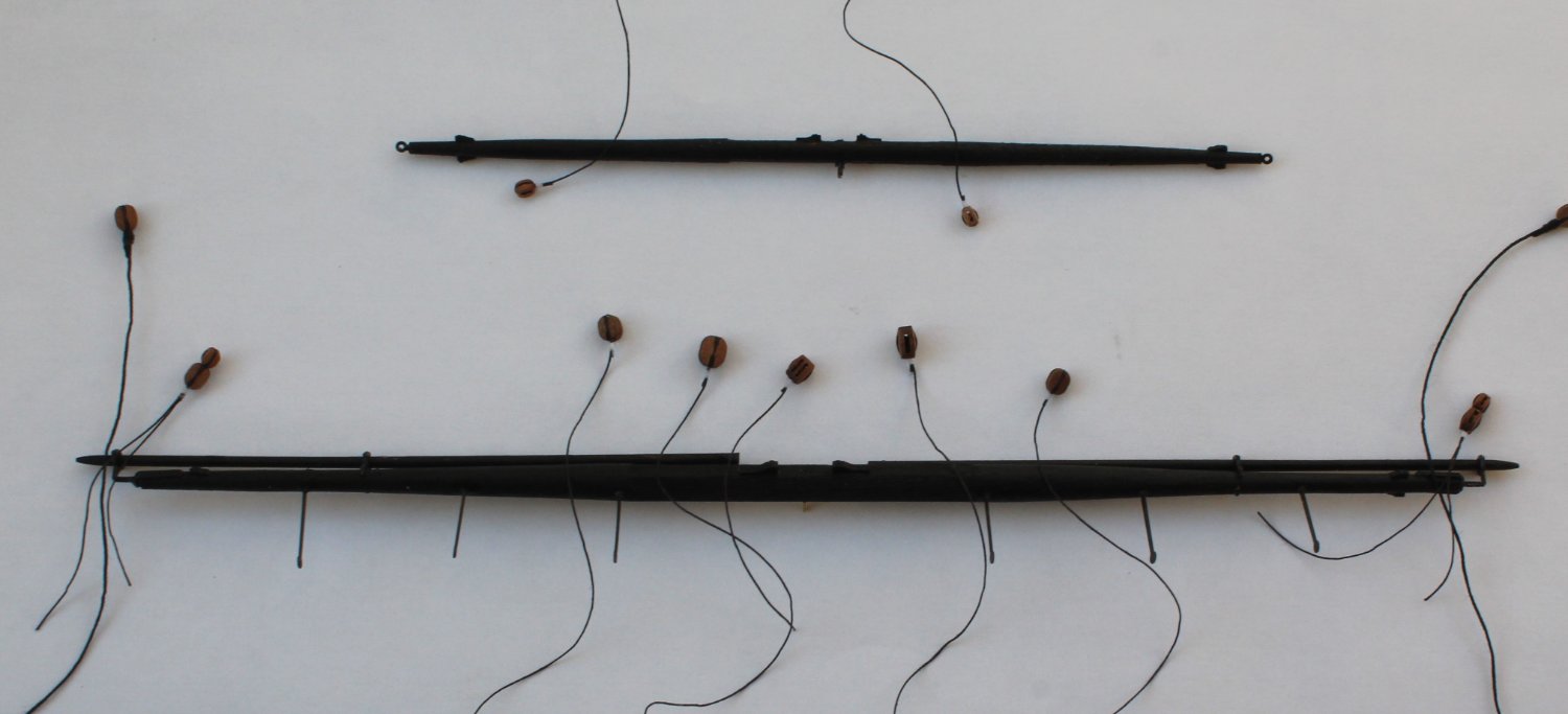
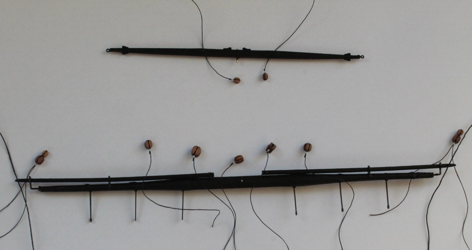
Top and Topgallant Yards - Woodworking For the last two days I returned to the woodworking workshop to make all the top and topgallant yards, plus the staff ensign. Apart from creating a lot of sawdust as each yard was turned on my Proxxon mini lathe the task was completed without any problems. Once I had completed shaping all the yards all the cleats and ironwork were added. The yards are now ready to be painted black which will be done later today (after tea) as it is now time for my daily afternoon run. Once they have been painted black I will spend the few days seizing and adding the various blocks and foot stirrups rigging to each yard. I should be able to complete this work before my holiday next week. With a brass rod inserted in each yard the completed top and topgallant yards were pinned to the yards for a photo shoot. The Sphinx looks resplendent with all the yards pinned in place. The Staff Ensign The Mizzen top and topgallant yards The main top and topgallant yards The fore top and topgallant yards


- 476 replies
-
- 3
-
-
- sphinx
- vanguard models
- (and 1 more)
-
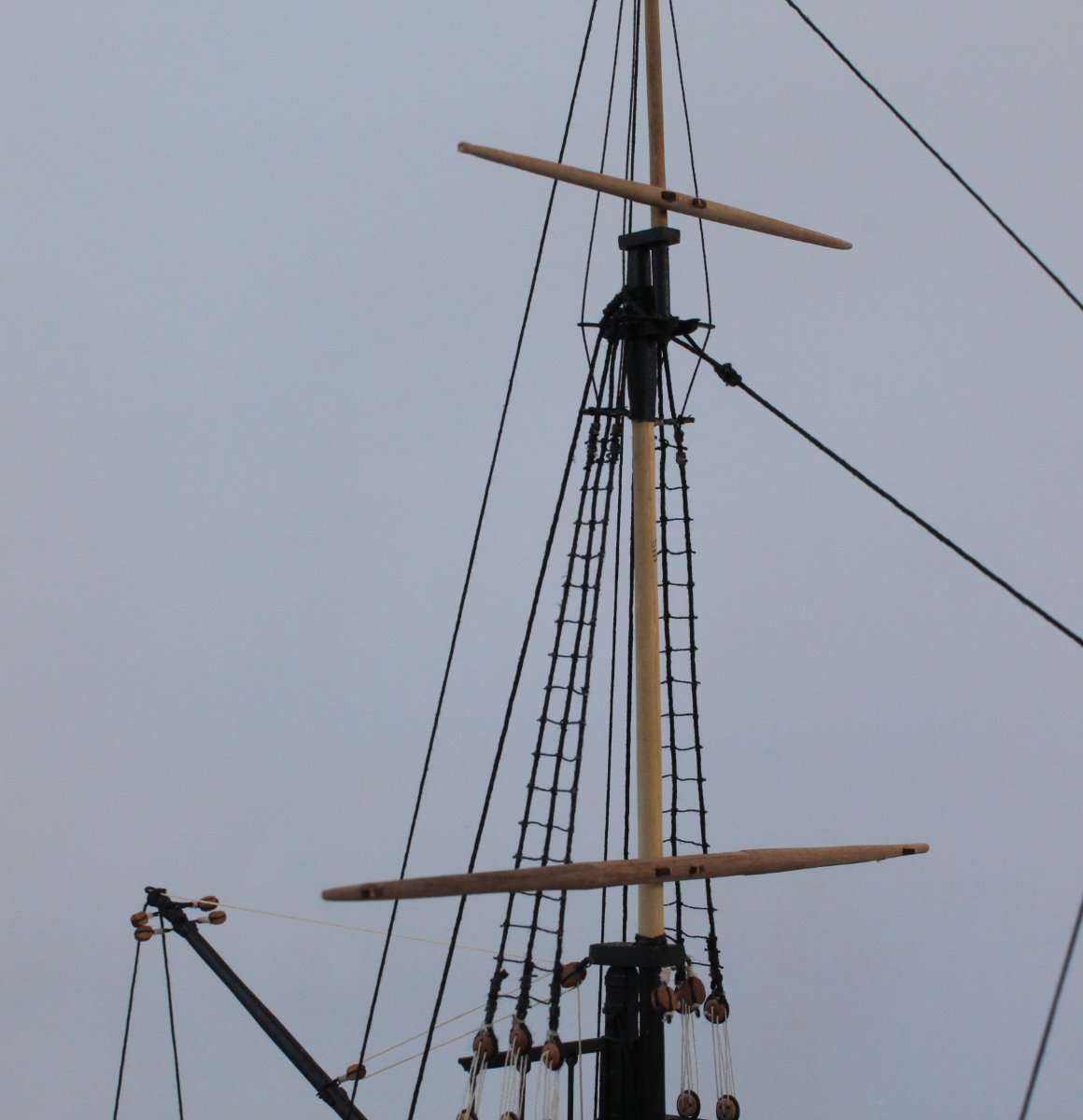
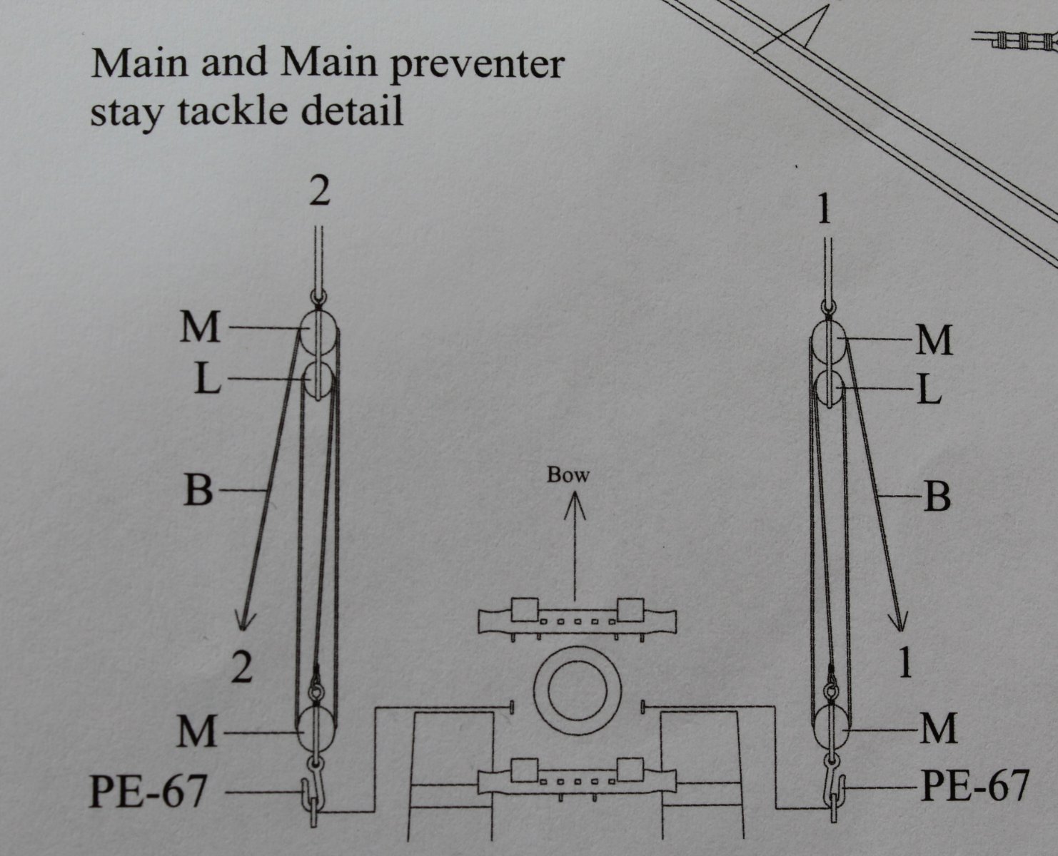
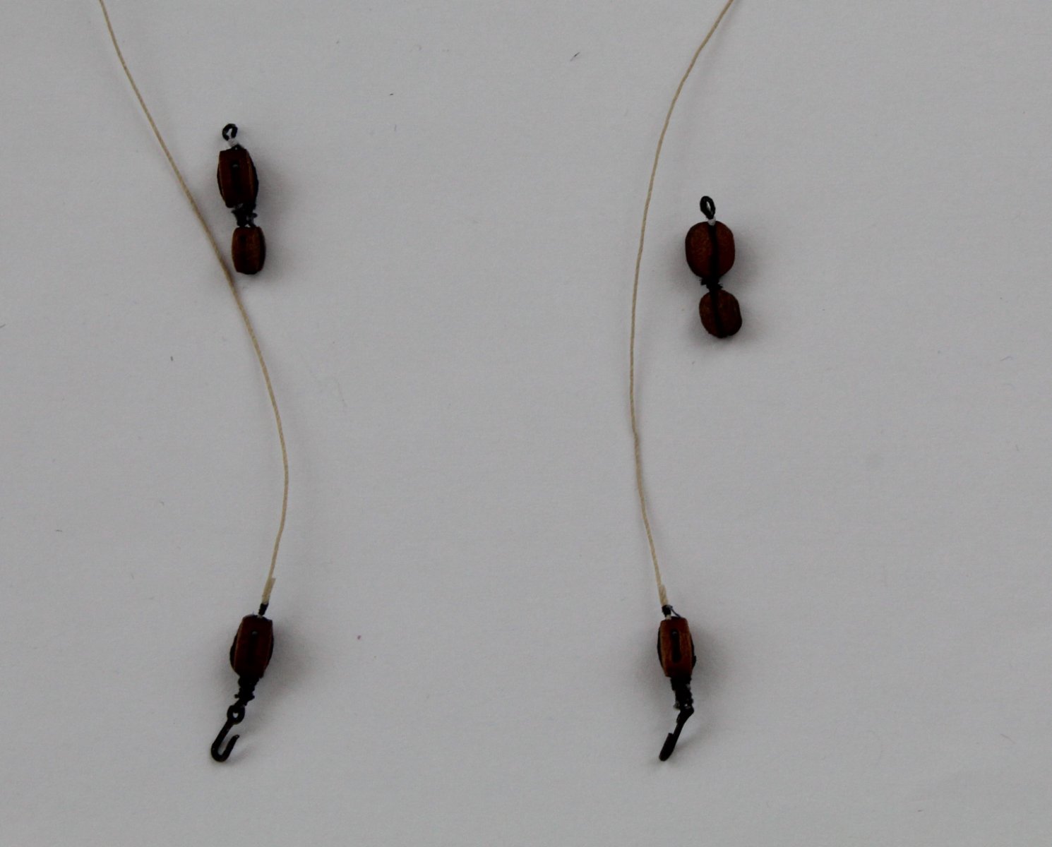
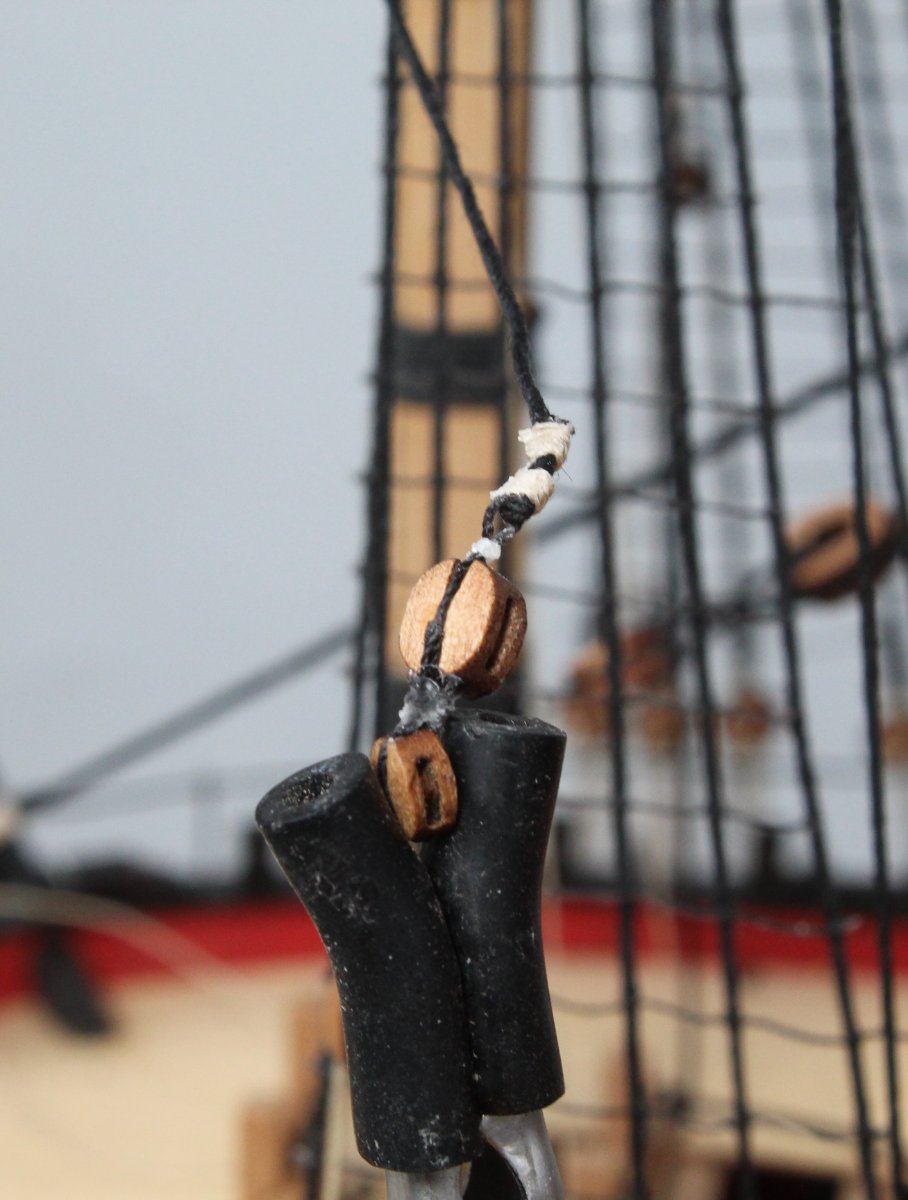
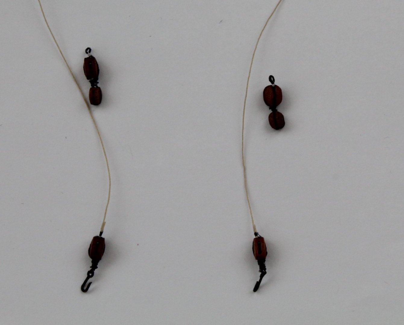
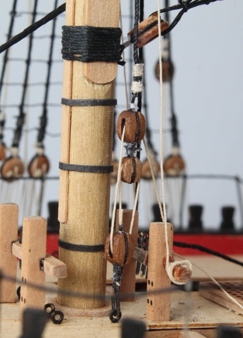
Main and Main Preventer Stay Tackle As indicated in my previous post I had made an fundamental error with belaying the main topmast stay and preventor as I had missed adding the tackle arrangement. The blocking arrangement for the main and main preventer stay tackle is shown in the picture below. Using the same techniques and methods which I have detailed in some of my previous posts I spent about an hour making the various block assemblies, as can be seen in the photo below. With the blocks assembly complete I then set about removing the main topmast stay and preventor from the bitt crossbeam. This turned out to be a relatively pain free 5 minute activity. The stay and preventor lines were then seized to their respective double block assemblies. I was able to hold the blocks in the quad hands which meant adding the seizing was an easy task to complete. You can see the end result of one of the seizing's in the photo below. With the double blocks added to the stay and preventor the two single blocks were hooked in to place. It was then a simple matter to run the 0.5mm natural thread through the blocks before belaying the free end to a belaying pin on the bitt crossbeam. Each side took about 15 minutes to rig with most of the time spent securing the free end around the belaying pin. Main Stay Tackle Pictures Main Preventer Tackle Pictures Over the next few days I will be turning my attention to the manufacture of 6 yards for the three top and topgallant masts. It will be nice to have a break from the rigging and hopefully I can complete the work before my luxury French river cruise next week.


- 476 replies
-
- 3
-
-
- sphinx
- vanguard models
- (and 1 more)
-
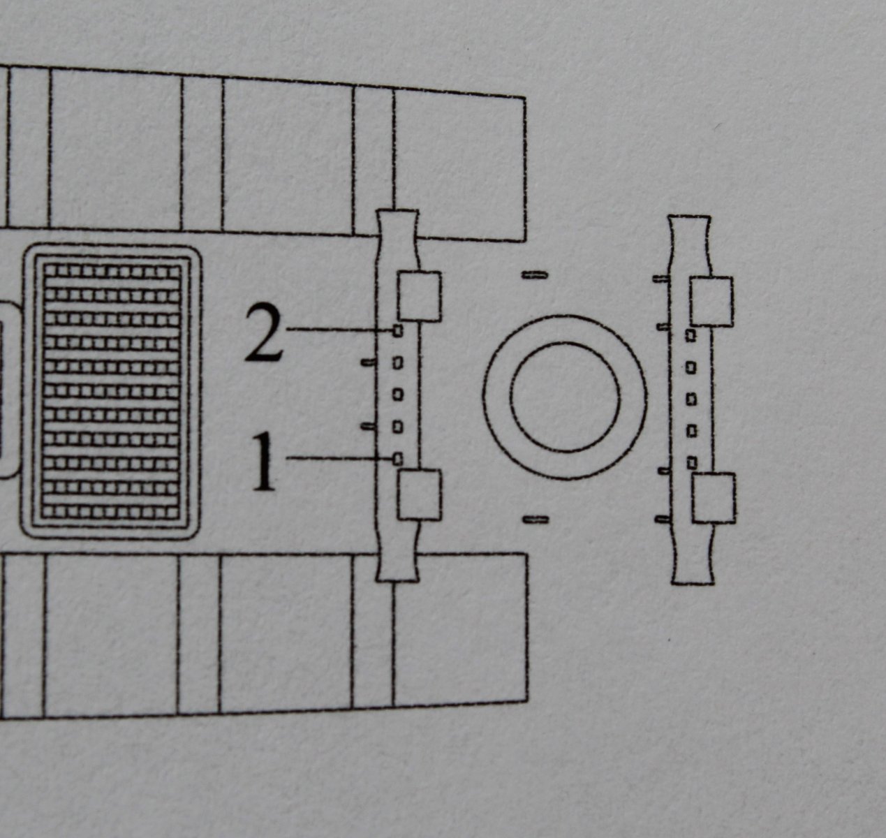
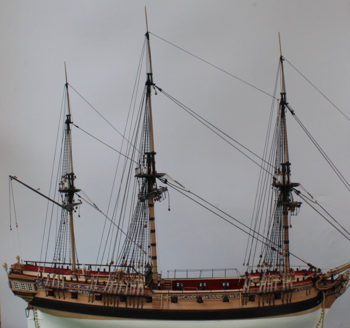
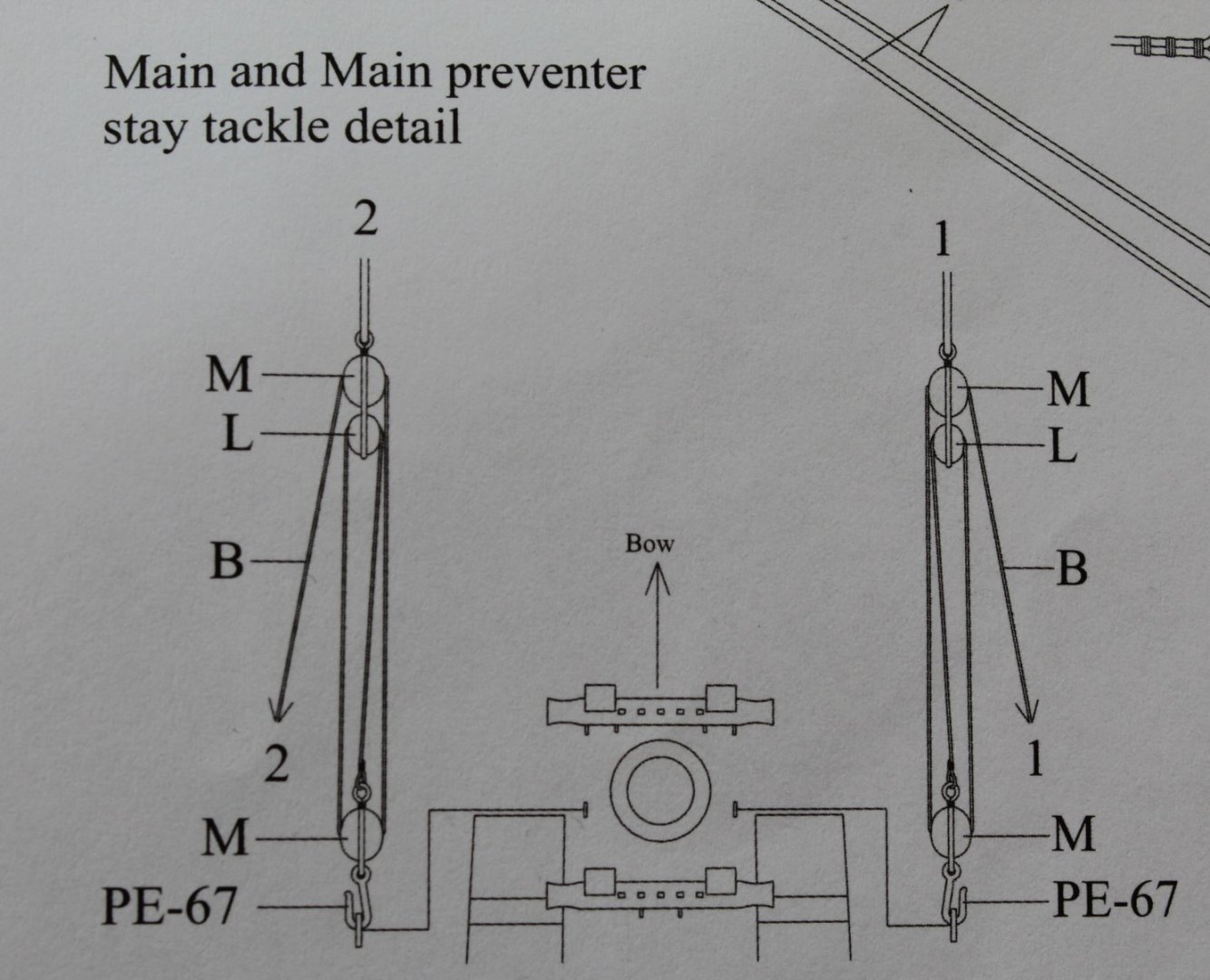
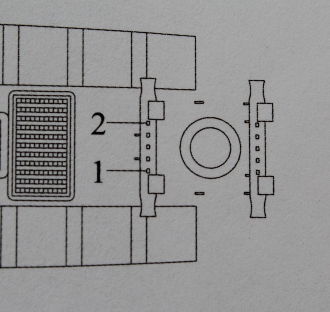
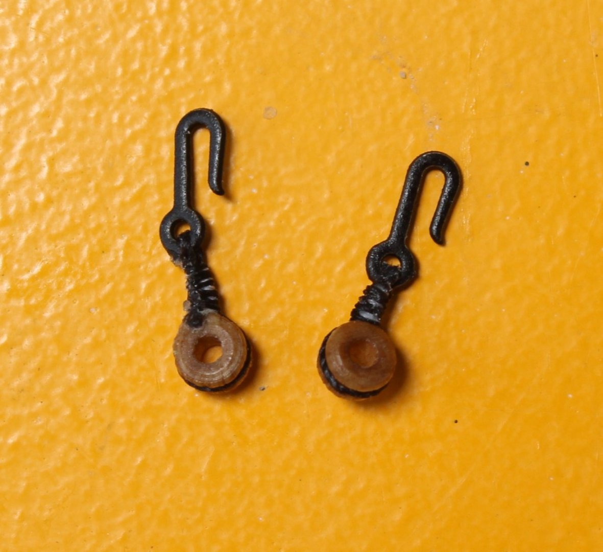
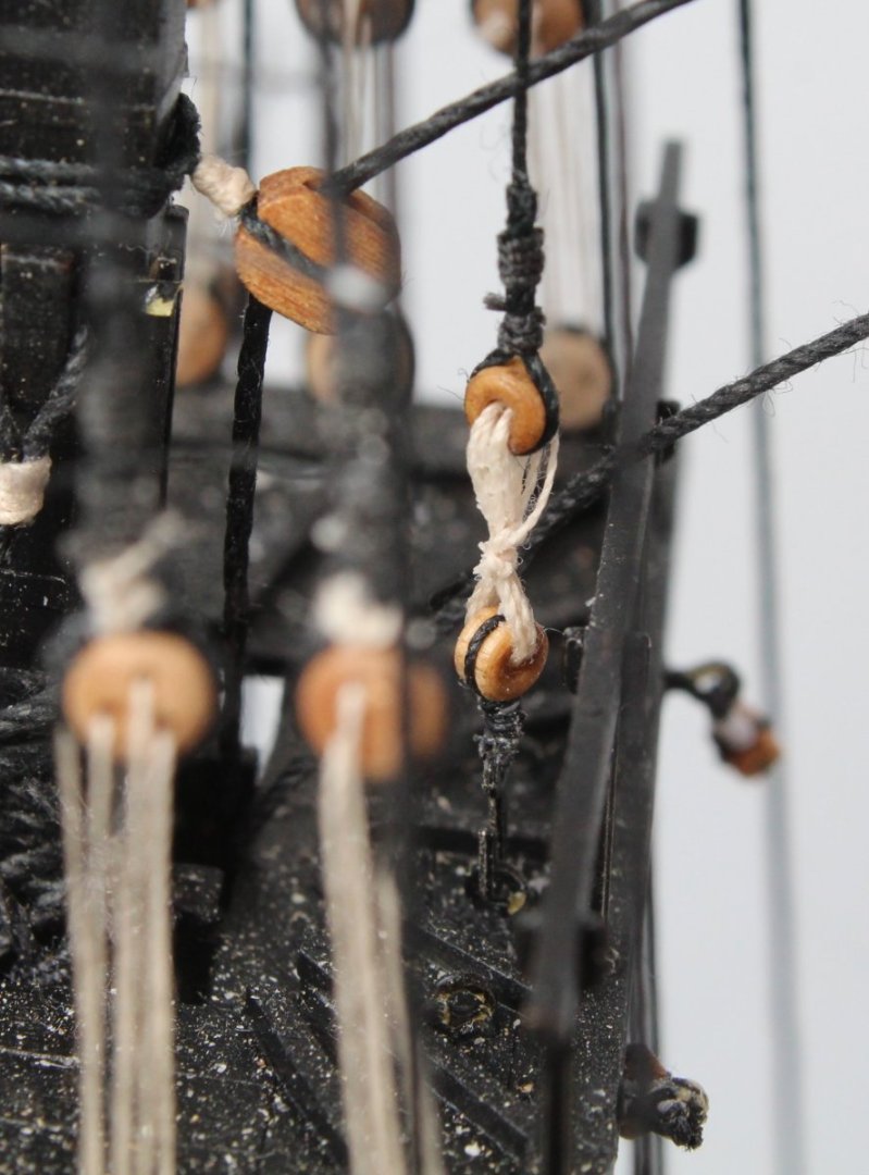
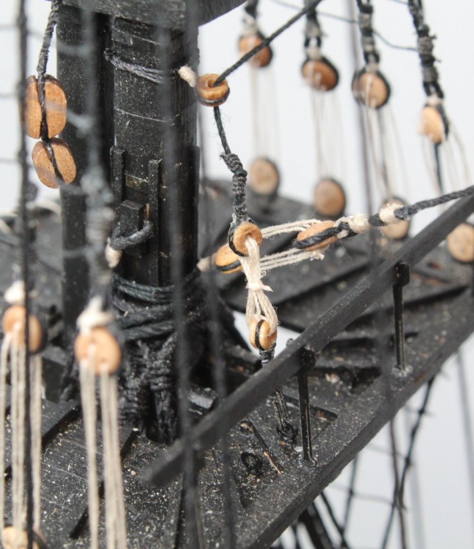
Rigging Plan Sheet 2 Completed (or so I thought!) I was really pleased with my morning work thinking I had finally completed all the tasks shown on rigging plan sheet 2. This was proven to be incorrect when I then discovered I had made a error with the belaying of the main stay and preventor. This error will be covered later on in the this post. Mizzen and Man Topgallant Stays This morning I pressed on with completing the work for the mizzen topgallant and main topgallant mast stays. These stays are to be belayed to the main and fore platforms respectively via a double thimble arrangement with the lower thimble secured to the platform eyebolt via a hook. Therefore the first task was to add a hook to the bottom thimbles. This did not take too long to complete and both completed thimble / hook arrangements are shown in the photo below. The next task was a little bit more complicated which was to add the other thimbles to the end of the stays. The main topgallant mast stay is fed down to the foremast platform via a thimble located on the fore topmast therefore adding the thimble to the end of the main topgallant mast stay was not so bad with the aid of the quad hands. The mizzen topgallant mast stay is fed down to the mainmast platform via a thimble located on the main mast therefore adding the thimble to the end of the mizzen topgallant mast stay was much more difficult as there was little thread available so I was unable to use the quad hands. In the end I decided to remove the stay from the mizzen mast so I could add the thimble without restrictions. Once the thimble had been added I was able to rerun the stay before making a new loop which was then placed over the mizzen mast. The bottom thimbles were then hooked to their respective eyebolts on the platforms. Two lengths of 0.1mm natural thread were then cut (approx 25cm each). It was then a case of using these threads to link both of the stay thimbles with their respective hooked platform thimbles. It was a bit awkward due to the limited access but I took my time and without any mishaps the task was soon completed. The photo below shows the rigged double thimble arrangement for main topgallant mast stay belayed to the foremast platform. The photo below shows the rigged double thimble arrangement for mizzen topgallant mast stay belayed to the mainmast platform. With the work on rigging all the stays finished I took some photos showing the completed work and I have attached a couple which can be seen below. The Sphinx is really taking shape. Checking The Plans Happy that the work was complete with regards to the stays I decided to double check the rigging plans. My eyes were then drawn to a detail for the main and main preventer stay tackle, as shown in the picture below. I was not overly concerned and thought it was something I needed to add. Whilst looking at the picture I noticed there was a number 1 and 2 shown at the top and also a 1 and 2 shown at the bottom which did confuse me somewhat. I soon realised I had made an error with how I had belayed the main topmast stay and preventor. When adding the main stay and preventor I had noted the 1 and 2 on shown on the stay and preventor lines and then wrongly assumed they should be taken to belaying points 1 and 2. The picture below shows the stays and preventor with the 1 and 2 identifiers which actually relates to the numbers shown at the top of the main and main preventer stay tackle. The 1 and 2 shown at the bottom of the main and main preventer stay tackle are the belaying points. The belaying point 1 and 2 for the main and main preventer stay tackle are shown in the picture below. Choosing not to use the belaying pins I wrapped the stay and preventor (minus the main and main preventer stay tackle arrangement) around the crossbeams, as shown below. I should be able to remove the both the stay and preventor belayed to the bitt crossbeam without too much trouble. It will then be a case of making up the required blocks and completing the rigging as per the plans.


- 476 replies
-
- 4
-
-

-
- sphinx
- vanguard models
- (and 1 more)
-
Great work, you have a very nice looking model
- 118 replies
-
- 3
-
-
- Duchess Of Kingston
- Finished
- (and 1 more)
-
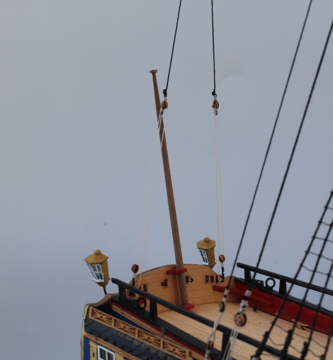
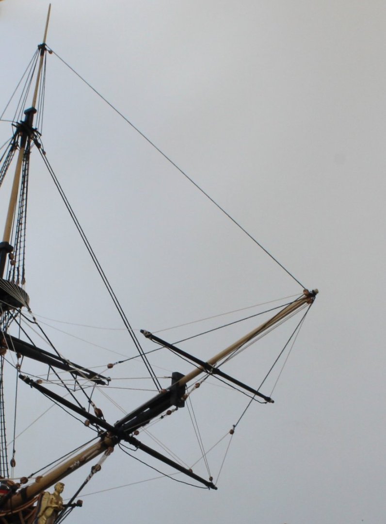
Fore Topgallant Mast Stay A length of 0.5mm black thread is used for the fore topgallant mast stay. The first step is to make a loop at one end of the thread which is place over the fore topgallant mast. Once the size of the loop as been adjusted so it is a goof fit over the fore topgallant mast the free end of the thread is fed through a 3mm single block located at the end of bowsprit, as shown in the photo below. Once the thread has been feed through the 3mm block the free end is then belayed, via a double thimble arrangement, to an eyebolt located on the end of the bowsprit cap. In the picture below I am in the process of adding the seizing a thimble to the end of the fore topgallant mast stay. The thimble is held in the quad hands as the seizing is added. The other thimble had already been secured to the end of the bowsprit cap during the manufacture of the bowsprit. Therefore the next task was to take a length of 0.1mm natural thread and tie one end to a thimble (at the bowsprit end). I then proceeded to link the two thimbles, as can be seen in the next photo. I have found it important to set the required tension in the stay early on in this process. After a few passes of the thread between the two thimbles the free end was tied off and the excess thread trimmed away. The final photo shows the completed stays and preventors for the fore mast, topmast and topgallant mast. Completing the main and mizzen topgallant mast stays will be a bit more fiddly due to the limited access around the fore and main platforms. That said I think I should be able to complete these stays in the next day or two. Once complete my attention will then turn to the manufacture of top and topgallant yards which I should be able to complete before my wife and I leave for our trip to France at the end of the month.


- 476 replies
-
- 4
-
-
- sphinx
- vanguard models
- (and 1 more)
-
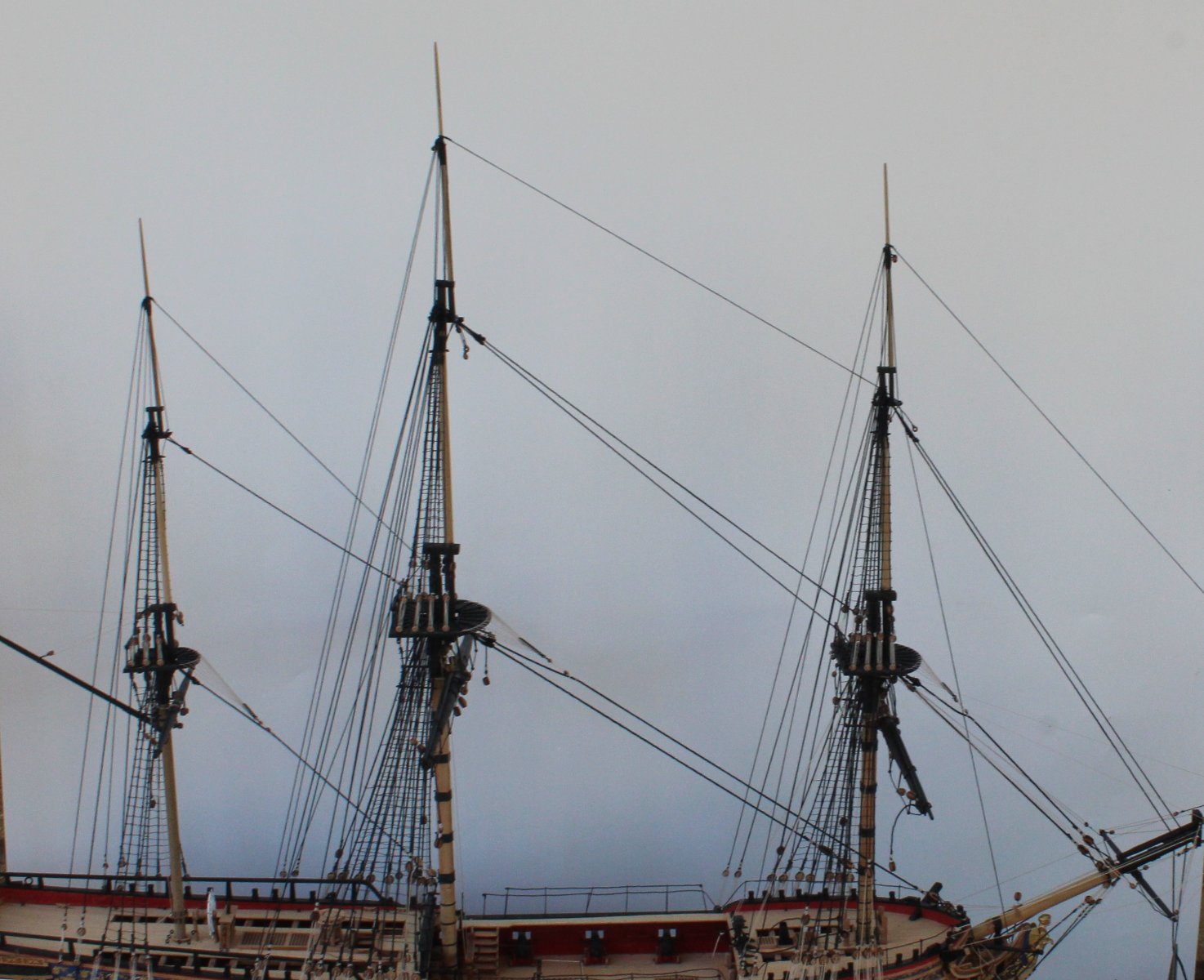
Topgallant Stays WIP I have now completed the work with regards adding the main and fore topmast stays and preventors. The first photo shows the fore topmast stay secured to the hull. There is an identical blocking arrangement on the starboard side for the topmast preventor. I did describe the method I used to seize the 3 block arrangement in my last two posts. You will probably note that I did make a slight miscalculation when added the double block section to the fore topmast stay as it is a bit closer to the single block section that I had planned. That said I think it looks OK so I have no plans to redo it. With the topmast stay work completed it was time to move on to the topgallant mast stays. The mizzen topgallant stay feds through a thimble on the main mast and will then be belayed to the main mast platform via a double thimble arrangement. A hook will be added to the lower thimble so it can be added to one of the platforms eyebolts. The main topgallant stay feds through a thimble on the fore topmast and will then be belayed to the fore mast platform via a double thimble arrangement. A hook will be added to the lower thimble so it can be added to one of the platforms eyebolts. The fore topgallant stay feds through a single block located right at the end of the bowsprit before being belayed to the bowsprit cap via a double thimble arrangement. I have added all the topgallant stays and they have been run down to their retrospective belaying points. The next two photos shows how the Sphinx is now looking. You can see some of the various tweezers I have used to apply some tension to the stays. My next task will be to add the double thimbles to each of these topgallant stays The final photo shows the Sphinx on my workbench getting ready for the photo shoot. Once I have completed all the work on the stays I turn my attention to all the yards and my first task will be to manufacture all the top and topgallant yards. Once that is done the actual yard rigging should not take too long to complete, famous last words!!


- 476 replies
-
- 2
-
-
- sphinx
- vanguard models
- (and 1 more)
-
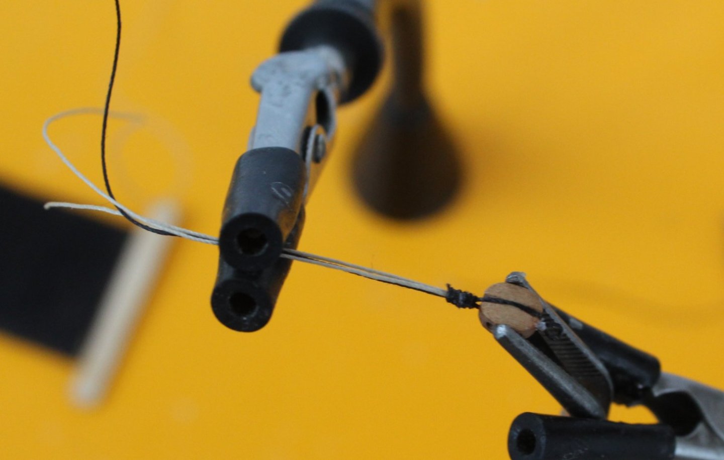
Take two - Fore topmast stay block arrangement I detailed the method I used for seizing the fore topmast stay and preventor blocking arrangement in my last post. I also indicated that I thought the seizing was a bit to chunky and that I would need to redo it. Take two turned out much better as can be seen in the photo below. When adding the eyebolt I used black tying thread this time rather than the 0.1mm natural thread. This does produce a much better end result. I also used ratline thread for the seizing to link the 4mm block to the 5mm block which again produced a much better result, maybe it is still a tad too chunky, but it is Ok.

- 476 replies
-
- 4
-
-
- sphinx
- vanguard models
- (and 1 more)
-
You might be able to release it if you drip some acetone down to soften the ca joints and then to gently prise it apart with a sharp blade, but it is risky. I think I would be more inclined to leave and remove straighten the crooked edge. You can add filler or wood offcuts to fill any gaps before painting. Great work nonetheless. Glenn
- 59 replies
-
- 2
-
-
- saucy jack
- fishing smack
- (and 2 more)
-
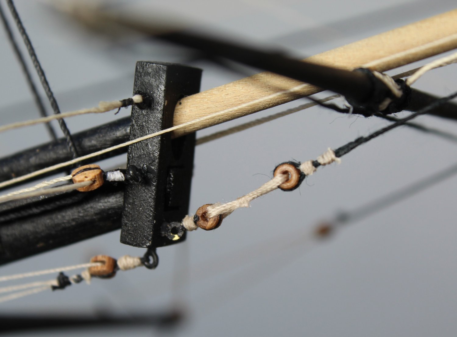
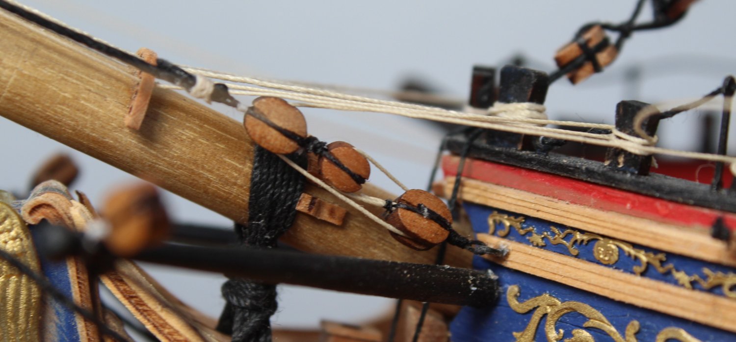
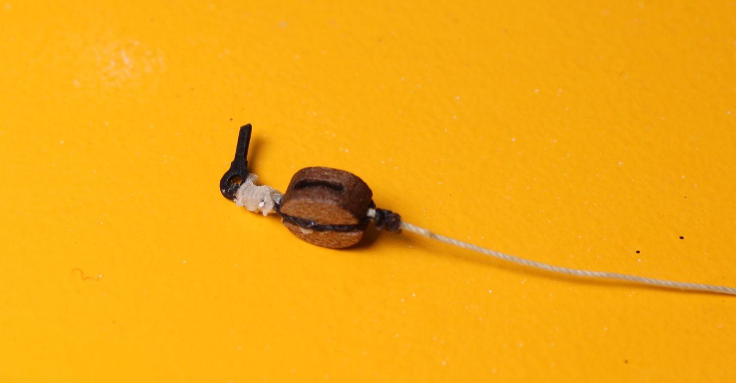
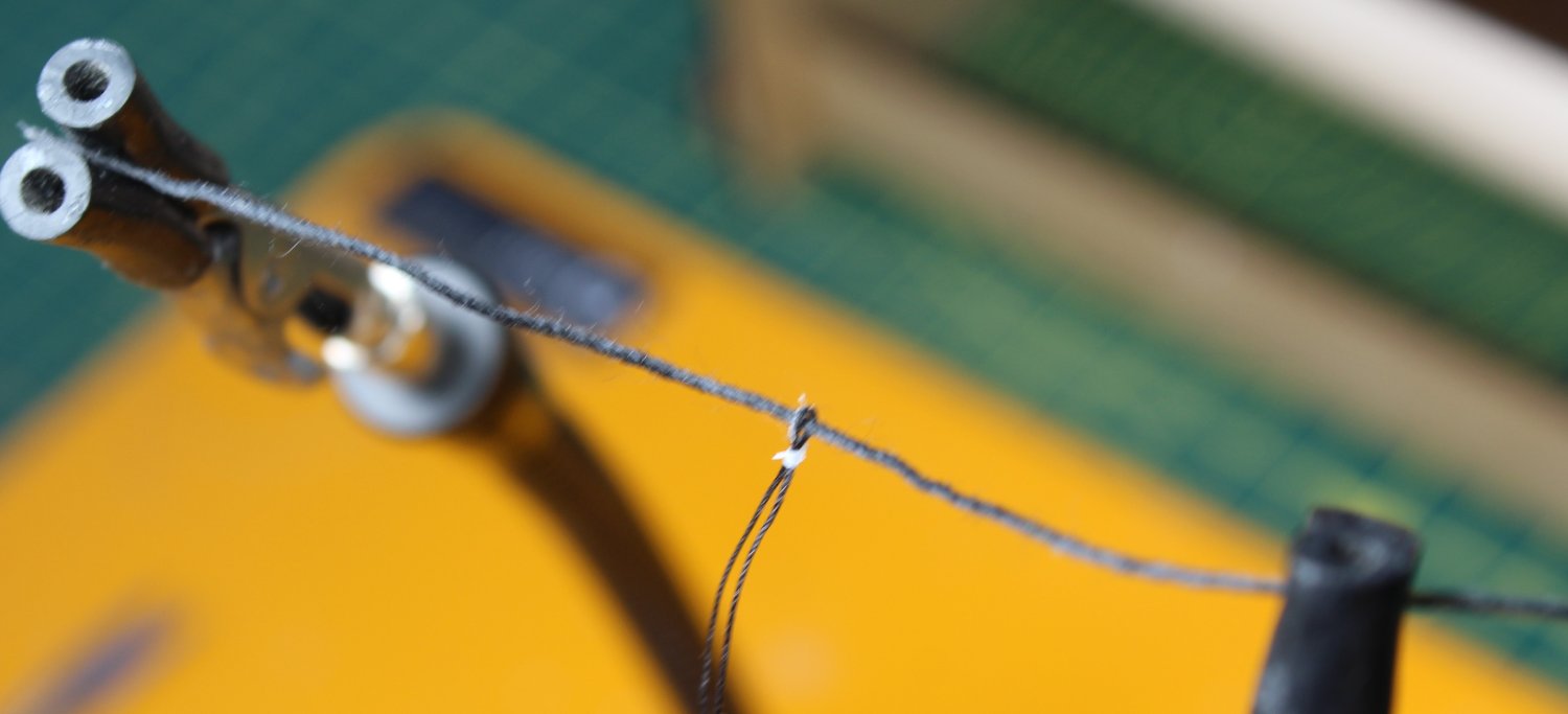
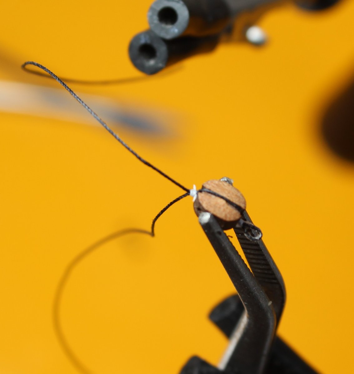
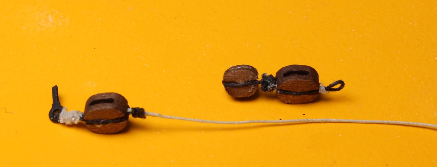
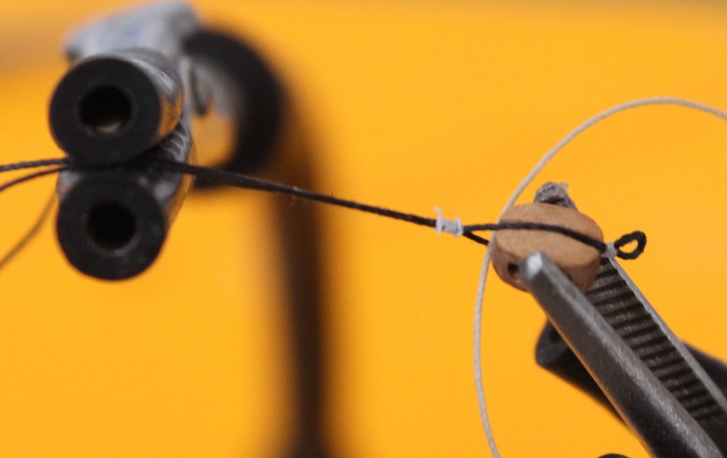
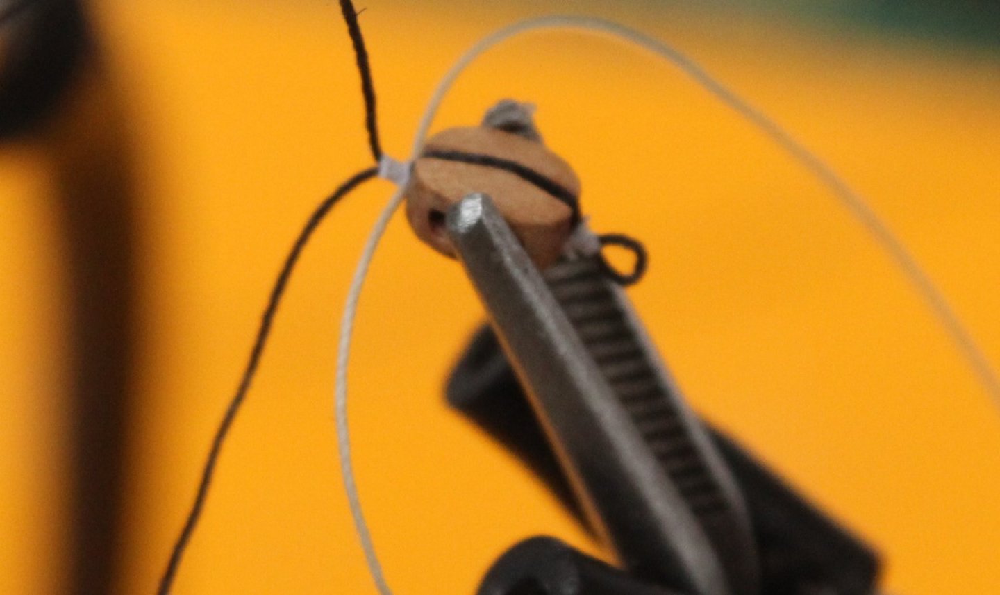
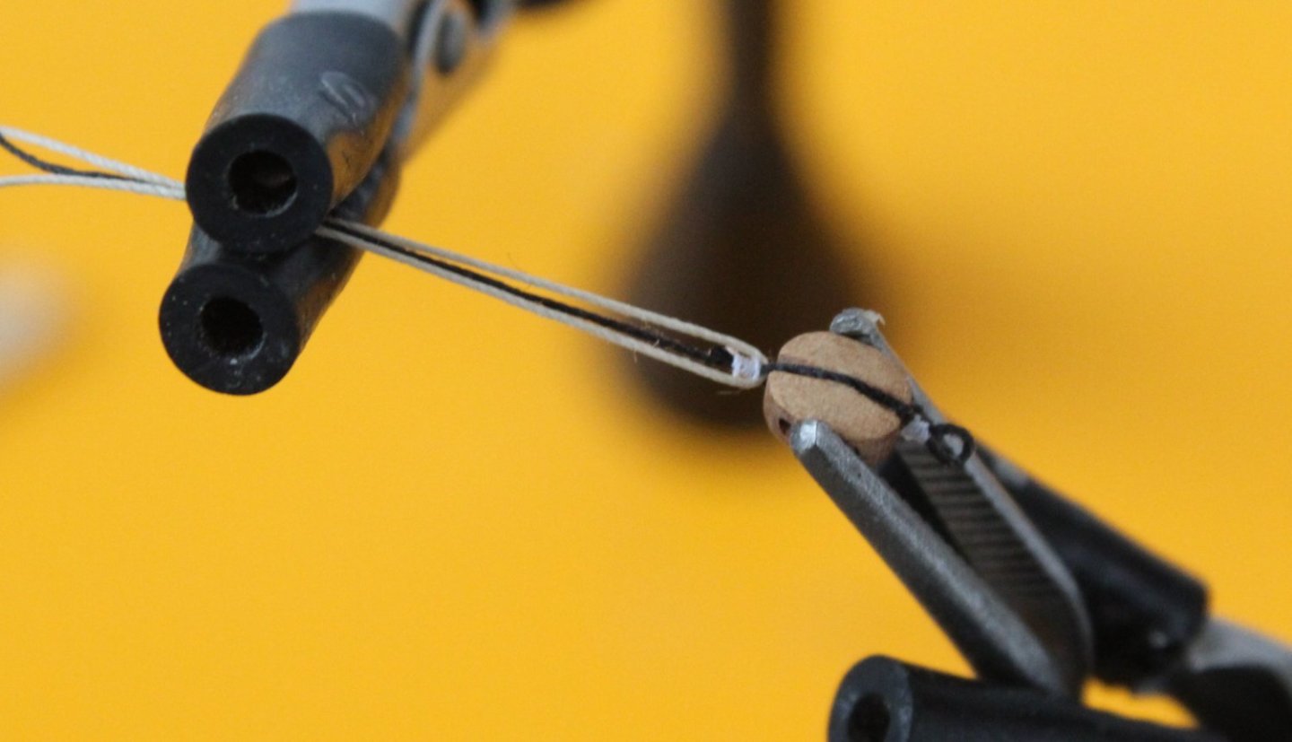
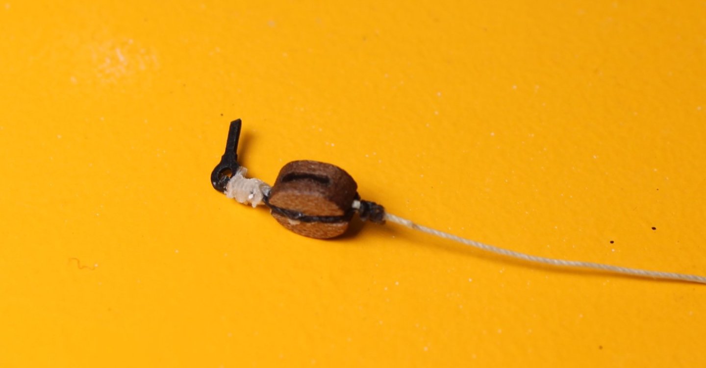
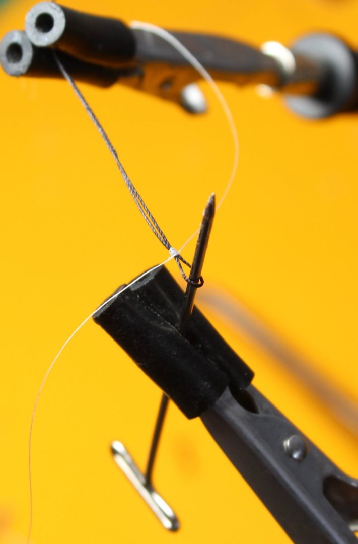
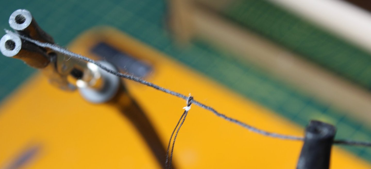
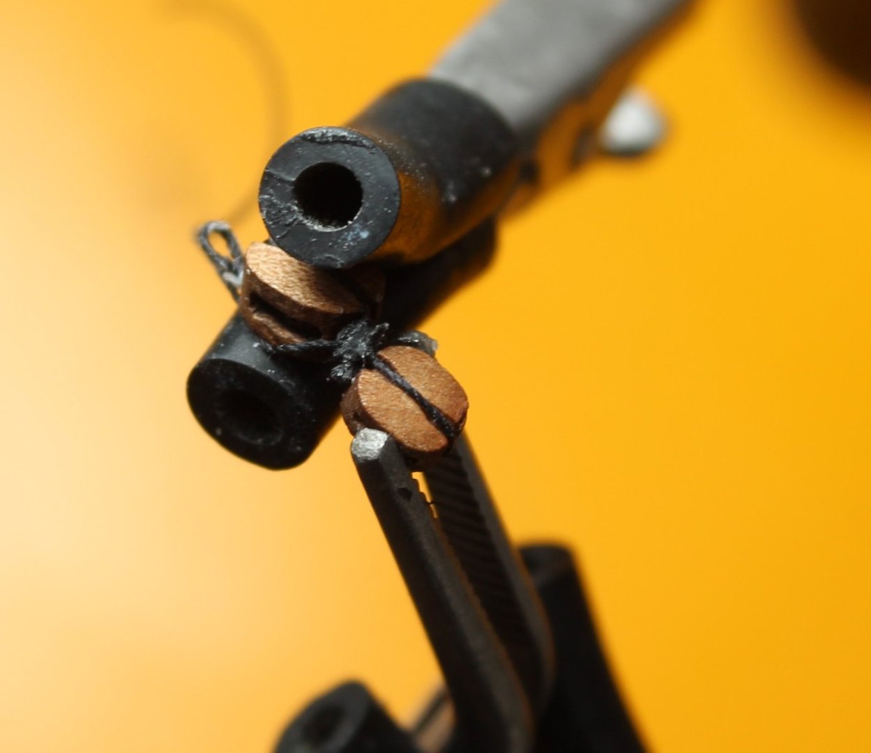
Fore Topmast Stay and Preventor Planning is the cornerstone of any success with regards to rigging, as I have learnt through many hours of rework when I have not planned ahead. With regards to the fore topmast stay and preventor I took a good look at the rigging plans. As can be seen in the photo below both the stay and preventor are fed through holes located on the either side of the bowsprit bee. Once the stay and preventor have been fed through their respective bowsprit bee holes then are belayed to thimbles located on the end of the 5mm / 4mm single block arrangement. A second 5mm single block is secured to the hull via an eyebolt. The blocks are then linked together using 0.25mm natural thread and the free end is belayed to one of bow catheads. The 3 block plan arrangement and rigging is shown in the photo below. The first task was to check the 0.25mm natural inter-block rigging thread could be fed through the various block holes. As seen in the photo below the thread would pass through the block holes without any problems. I decided to start with securing the single 5mm block to an eyebolt. With the 5mm block held in the quad hands a length of 0.25mm black thread was wrapped around the block. A long length of 0.25mm natural thread was also added at this stage, as shown in the photo below. Using some white fly tying thread the block was seized, as can be seen in the photo below. One of the two black thread end was trimmed. The other black thread will be seized to the eyebolt later on in the process. With reference to the next photo the 5mm block was reversed in the quad hands so the 0.25mm natural rigging thread could be seized, creating a pseudo thimble I used some ratline black thread to seize the rigging thread. Once seized the excess rigging thread was trimmed as can be seen in the photo below. It is now time to feed the black thread through the eyebolt. With the eyebolt in place black thread is held in place on the side of the 5mm block as shown in the next photo and is now ready to have the seizing added. I decided to use some 0.1mm natural thread to add the eyebolt seizing. I did check with the rigging plan sheets to ensure the eyebolt was correctly aligned with regards to the block, as can be seen in the two photos below. I think it was a mistake to use 0.1mm natural thread for the seizing as it looks a bit to bulky. Turning my attention to the double block arrangement I started with making a thimble which will be used to belay the stay / preventor thread. I took a length of 0.25mm black thread and using some white fly tying thread made a loop. The two free ends of the black thread were then pulled which reduced the loop diameter to the required size. It is a good idea to check stay / preventor would pass through the completed thimble, as shown below. Next the thimble was seized to the 5mm single block which is held in position using the quad hands. With the 5mm block held in one of the quad hands the 4mm block was positioned and held in place with another quad hand and the black seizing thread was wrapped around the 4mm block and seized, as can be seen in the two photos below. Again I think the seizing looks to bulky The final photo in this post shows how the blocks will be rigged. As I am not totally happy with how these finished blocks look I will redo to see if I can make a much better job of the seizing.


- 476 replies
-
- 5
-
-
- sphinx
- vanguard models
- (and 1 more)