Glenn-UK
-
Posts
3,175 -
Joined
-
Last visited
Content Type
Profiles
Forums
Gallery
Events
Everything posted by Glenn-UK
-
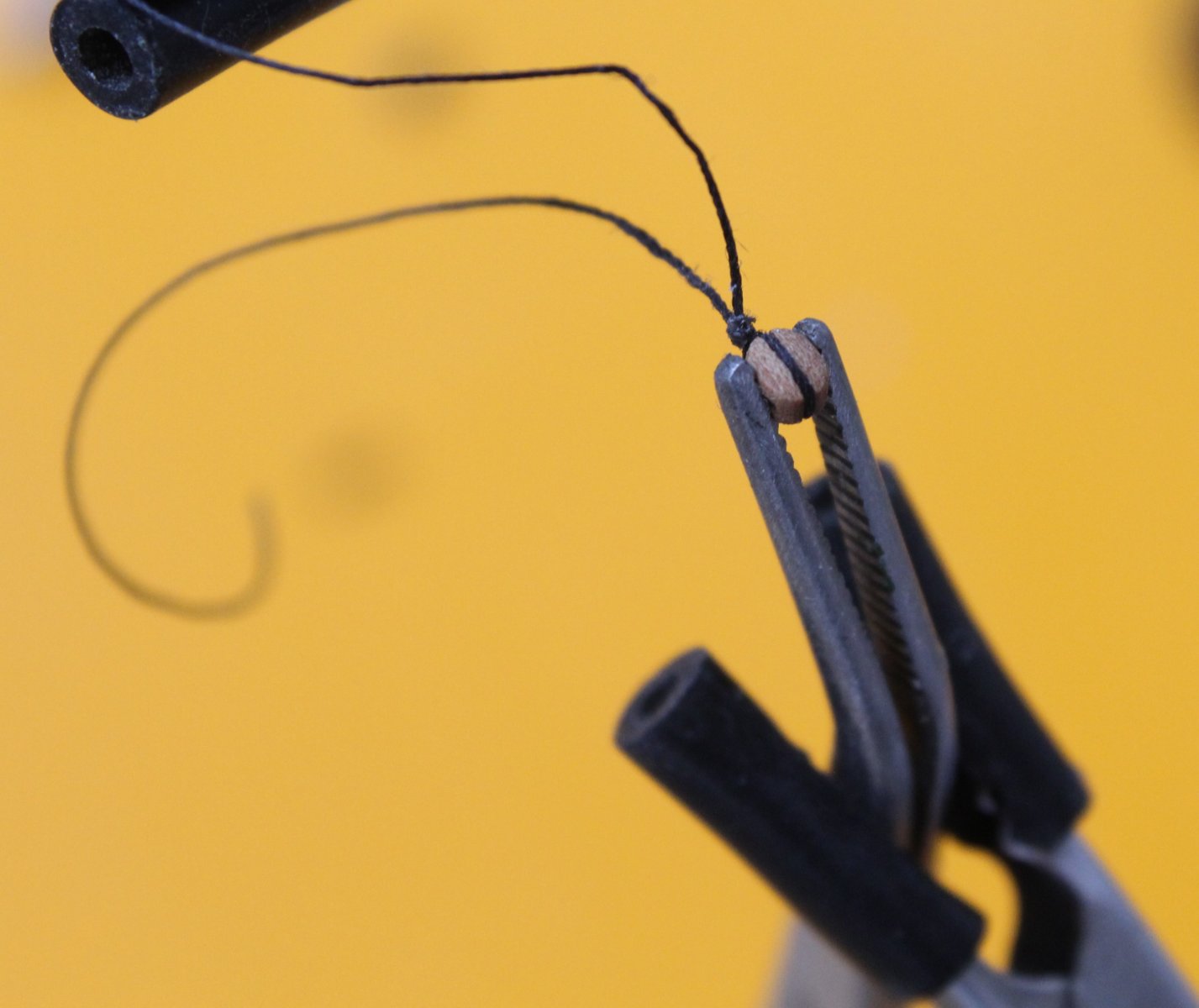
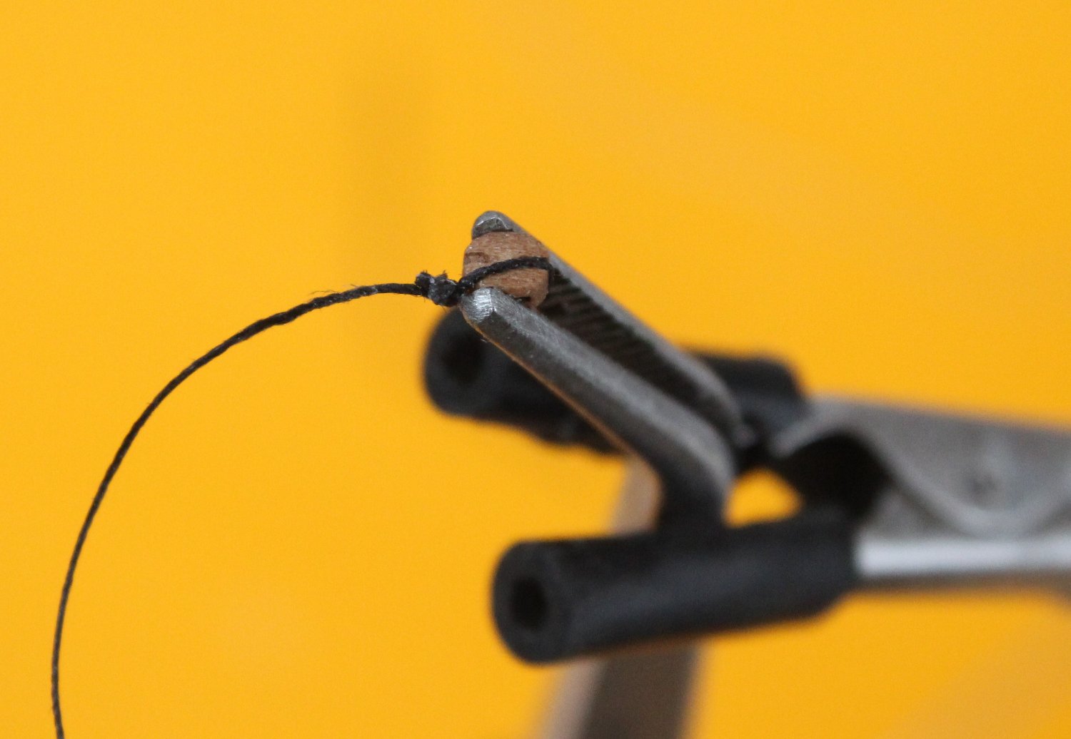
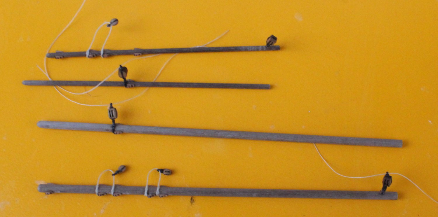
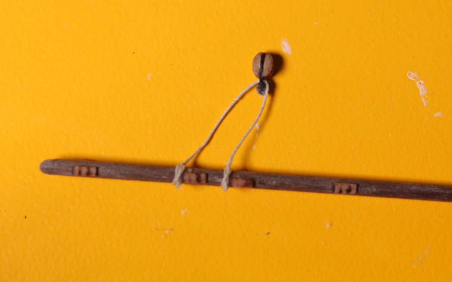
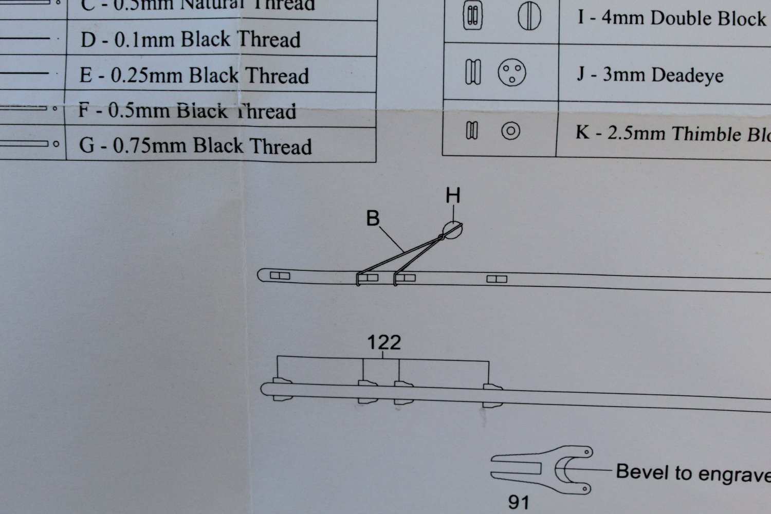
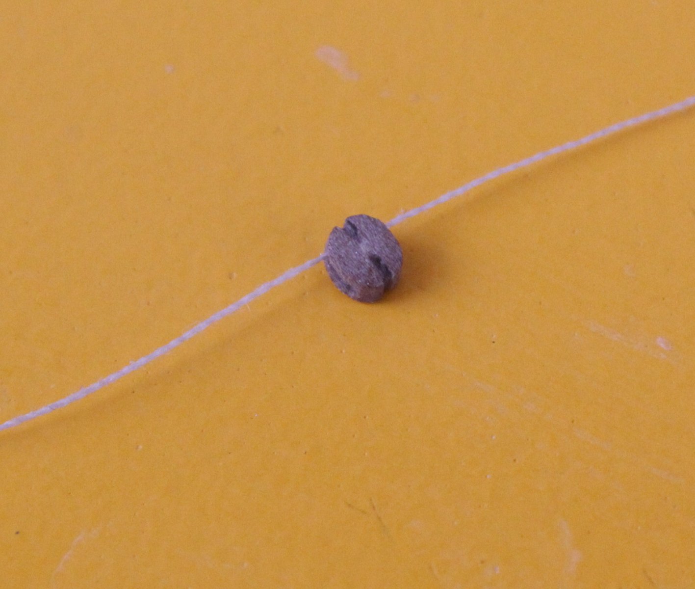
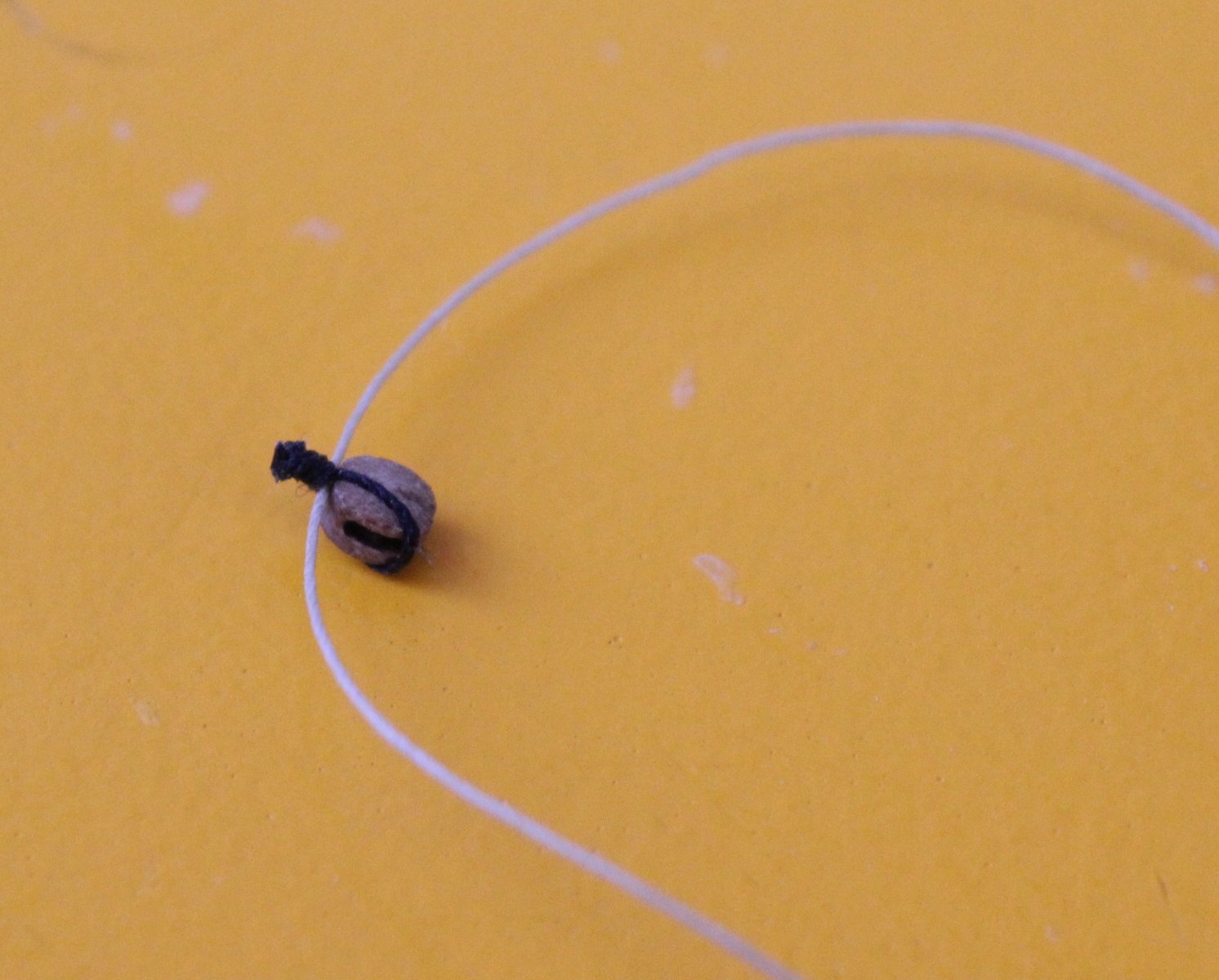
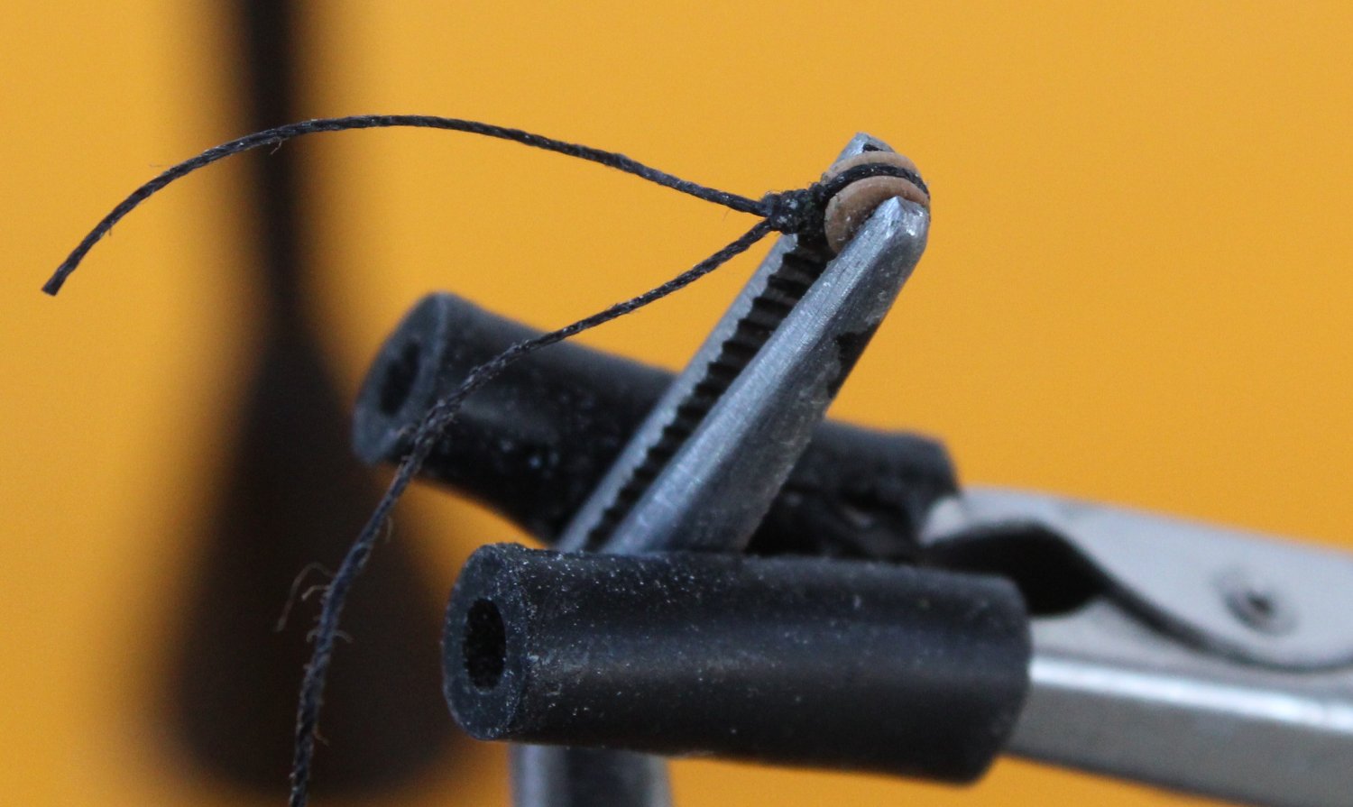
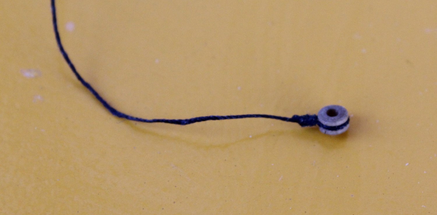
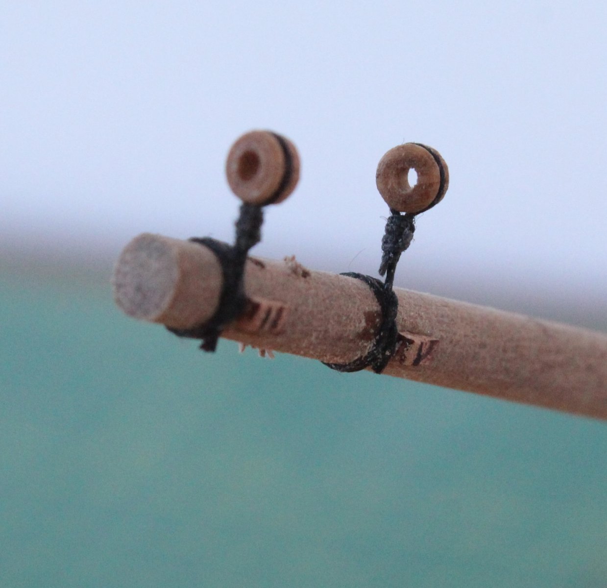
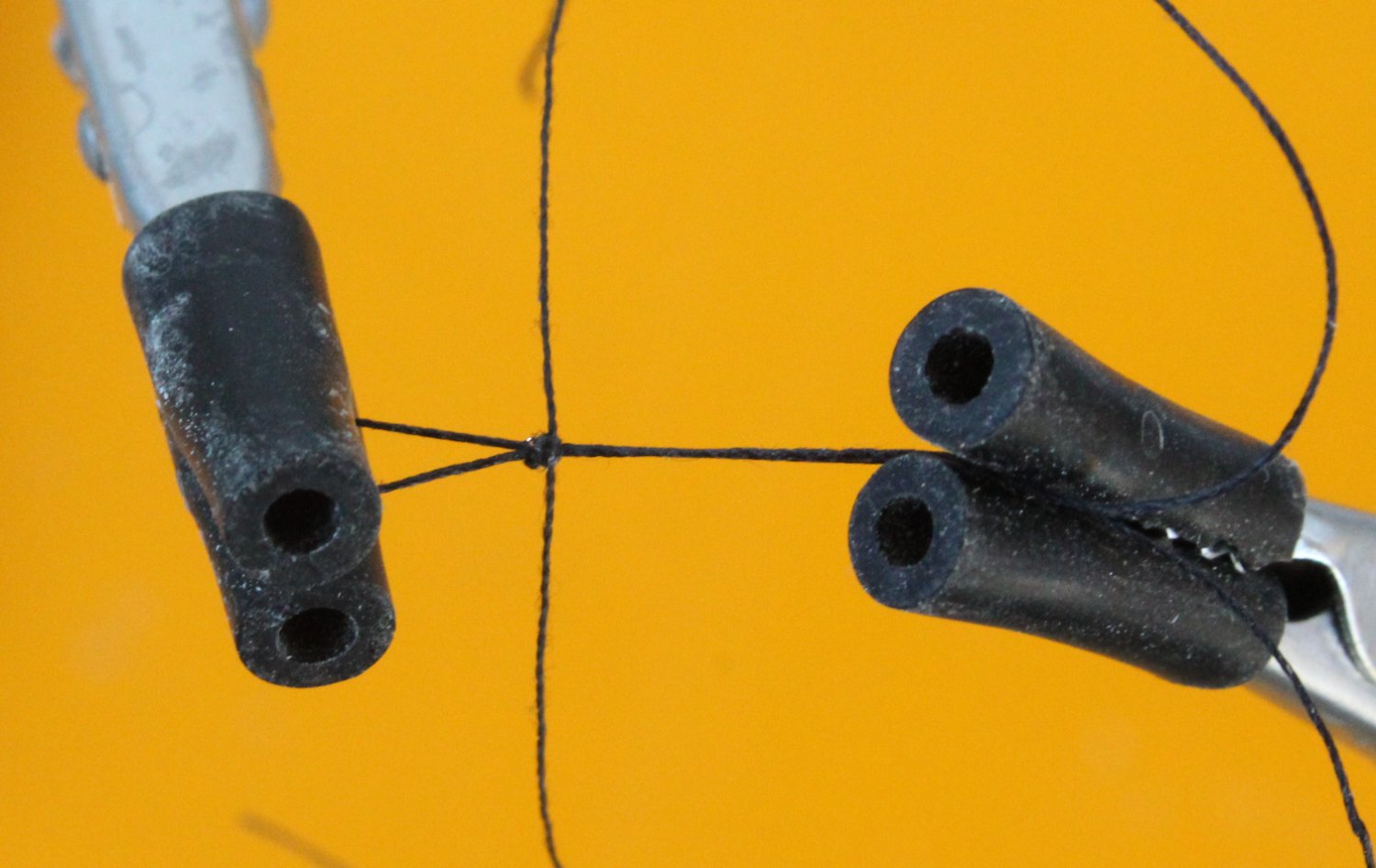
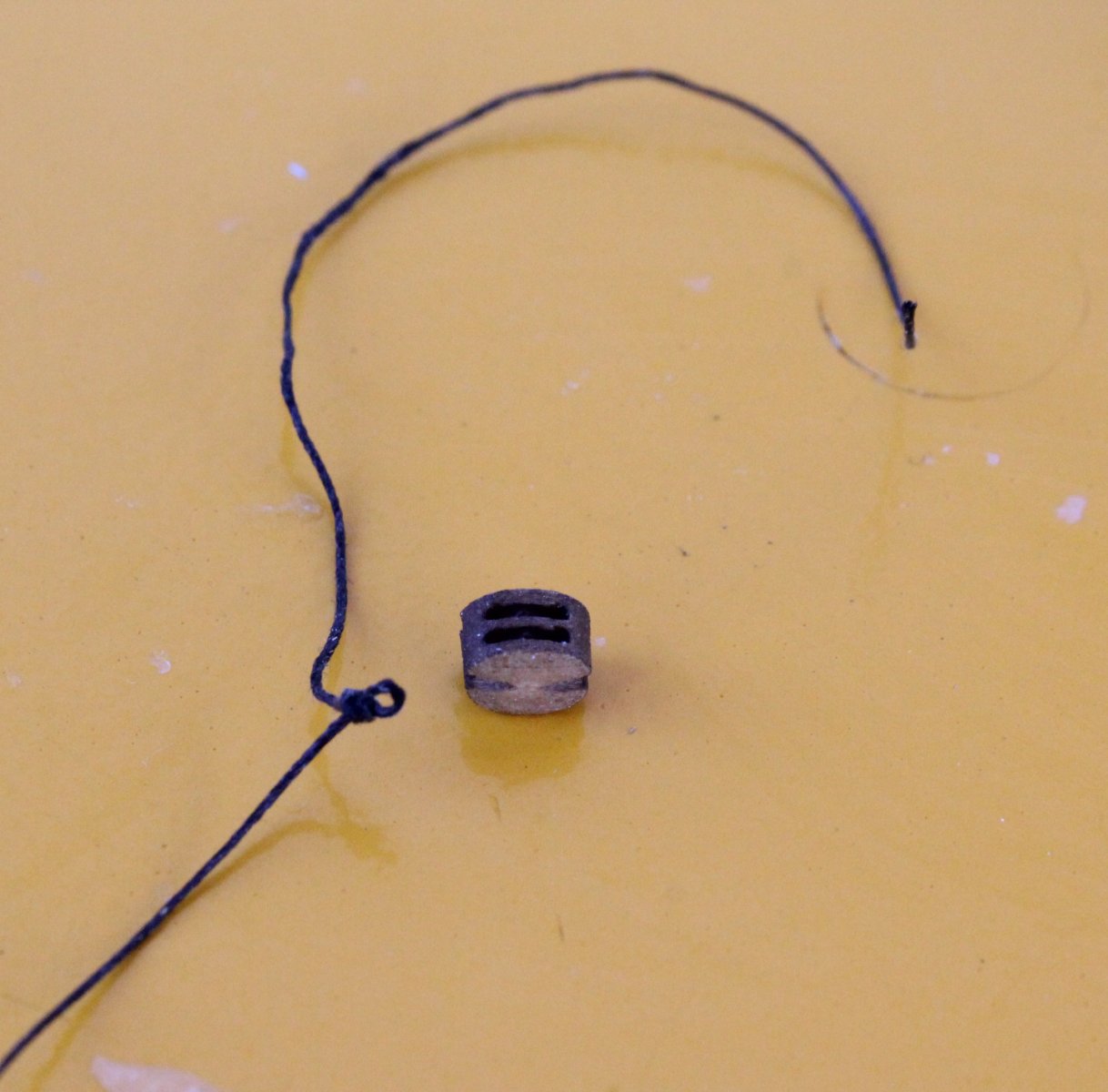
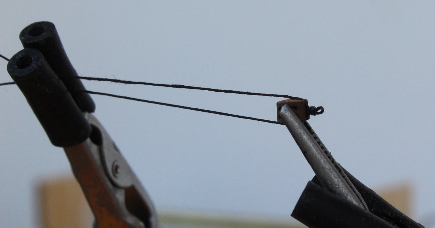
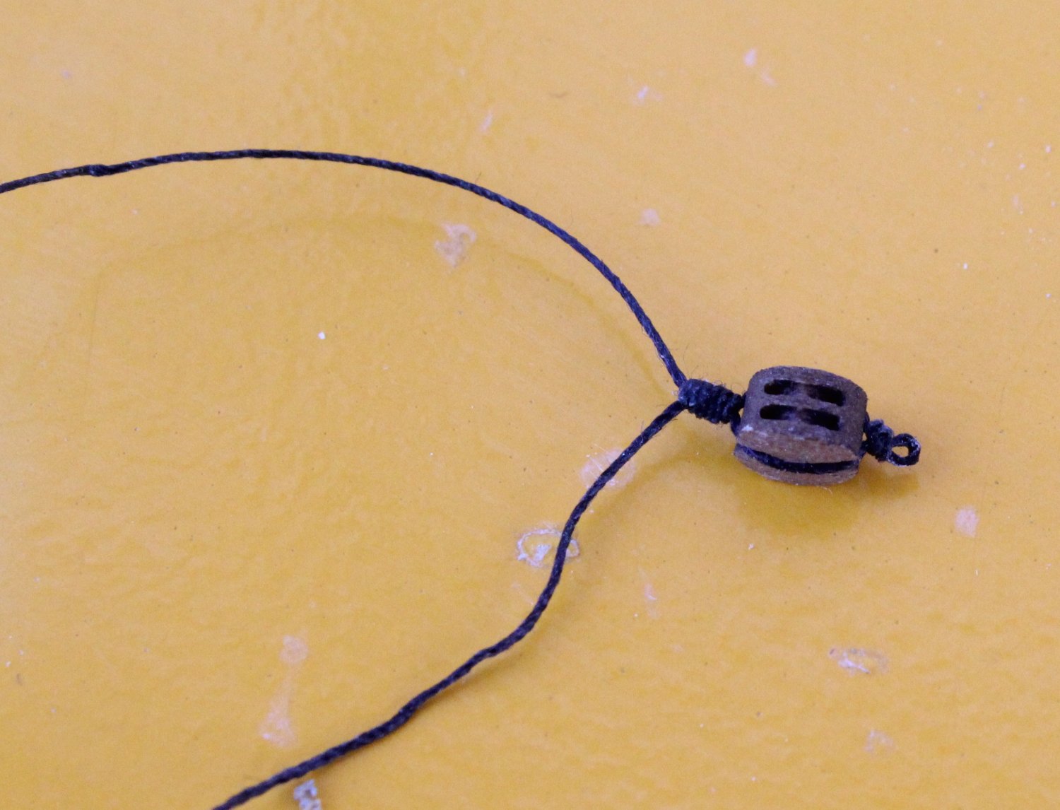
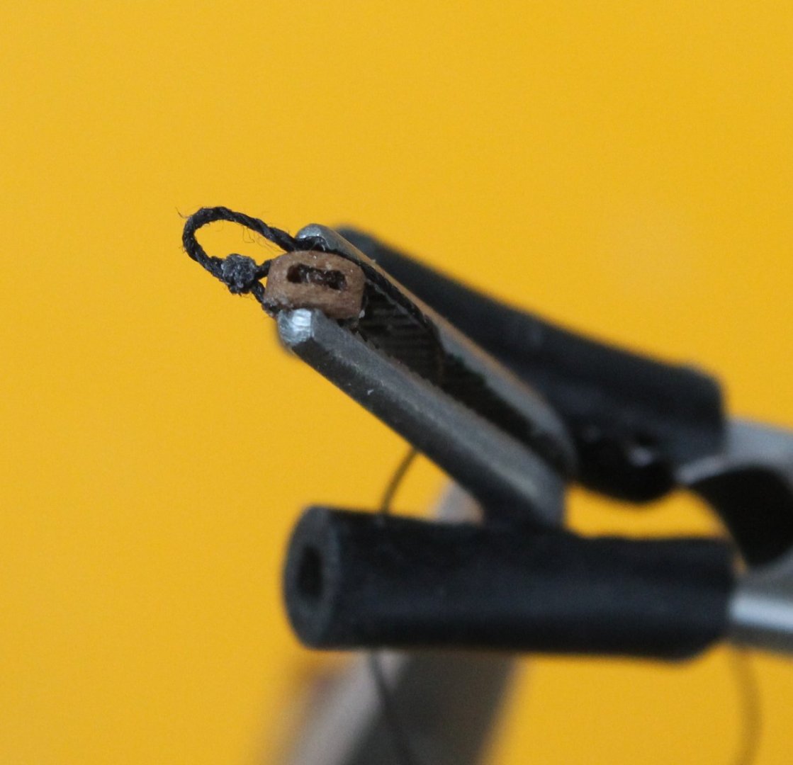
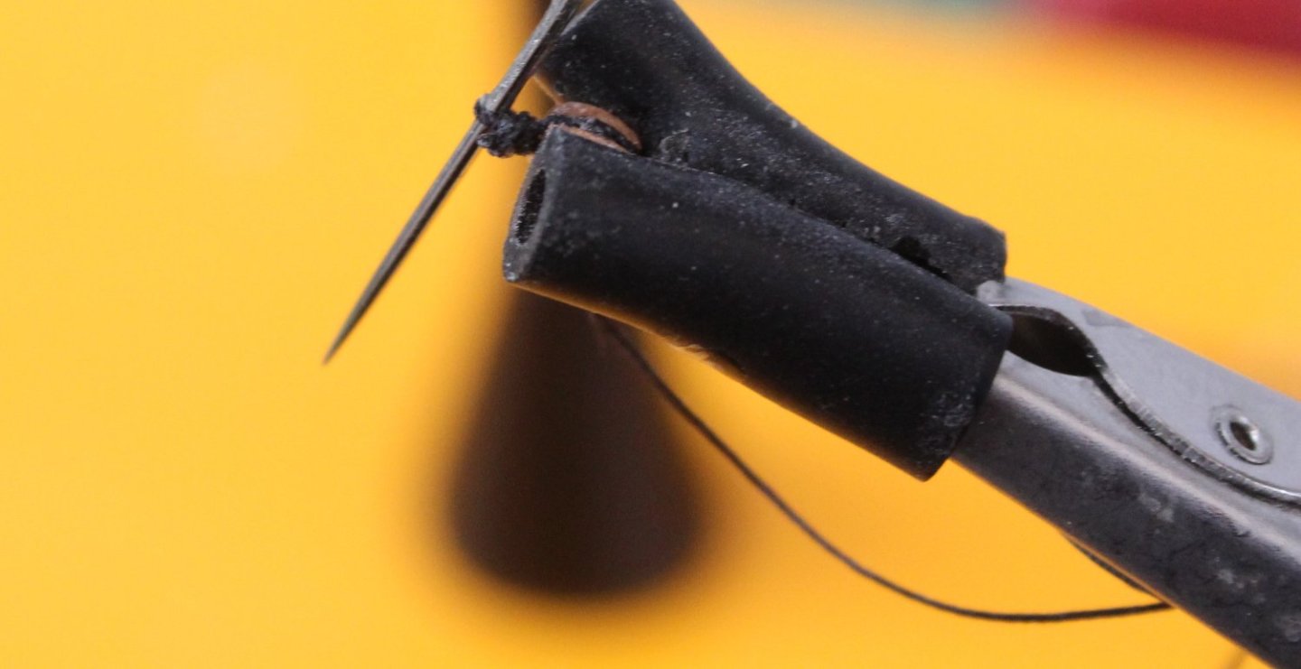
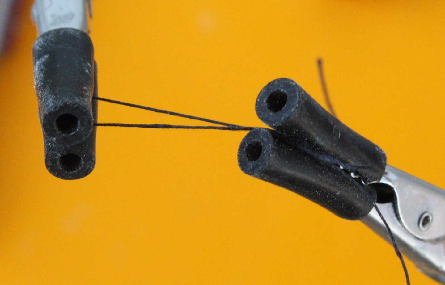
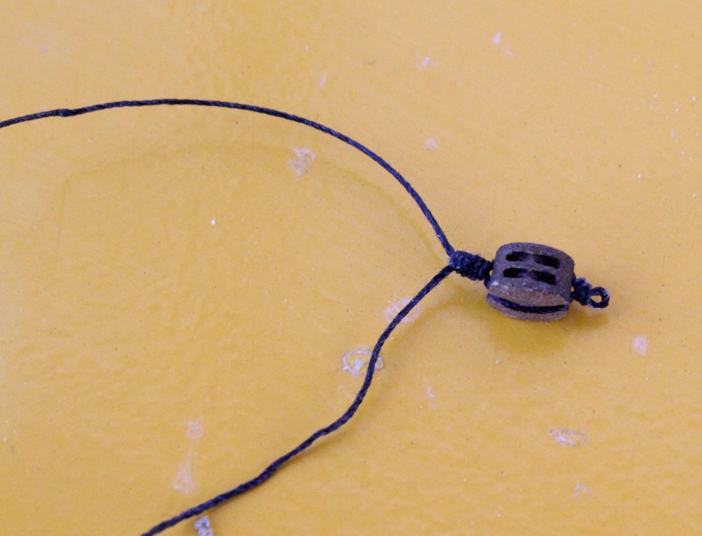
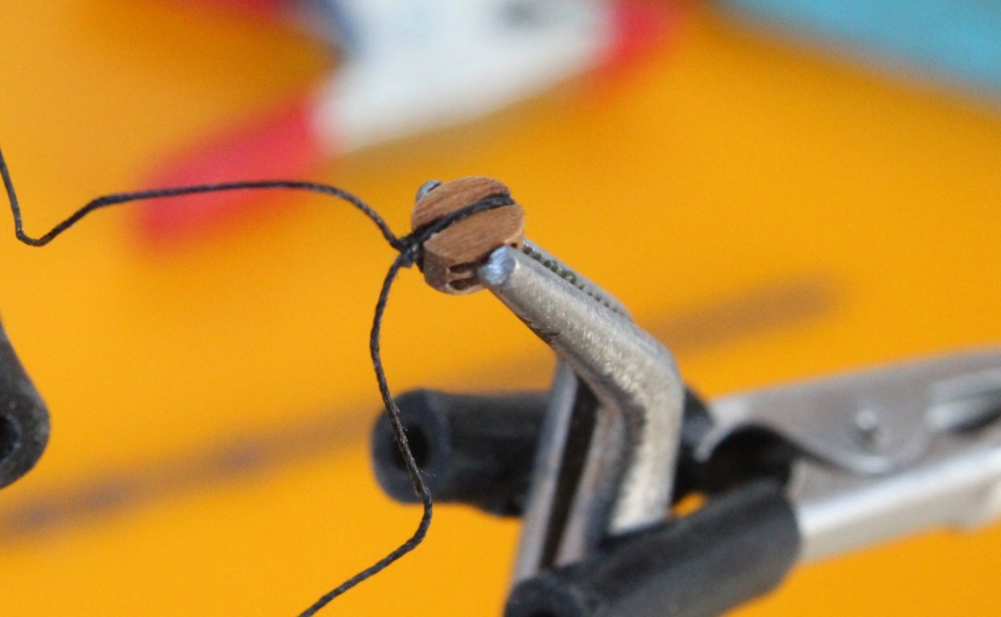
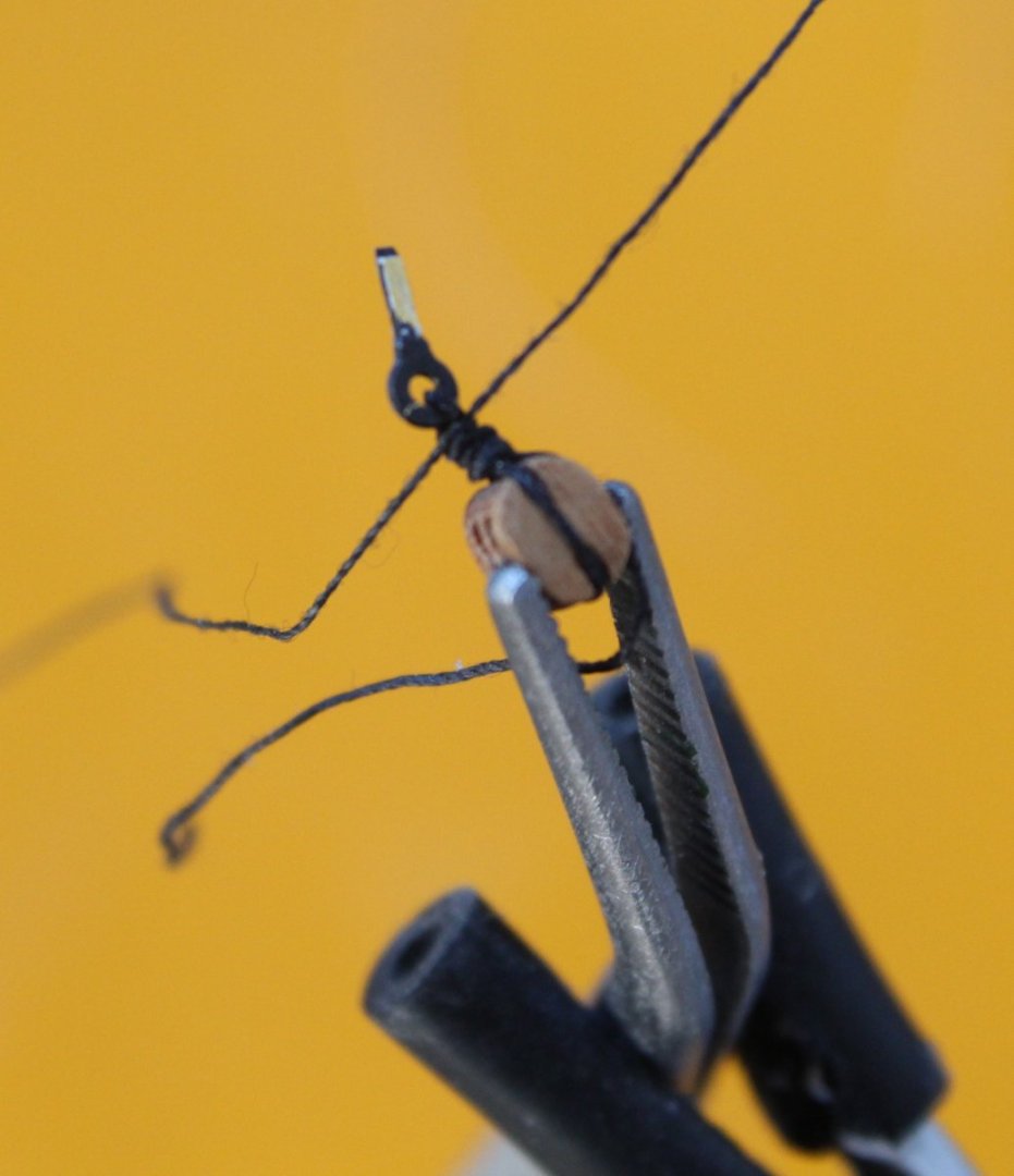
 026 - Adding Blocks Part 3 Main Gaff In my previous post I detailed a method of adding a simplified thimble to the bottom of a block which was required for the mizzen gaff. The main gaff requires two such blocks. I decided I should add a proper thimble to the bottom of the main gaff blocks. After checking the rigging thread would pass through the 3mm single block holes I wrapped a length of 0.25mm black thread around the first block and seized it with 0.1mm black thread. The seizing comprised 4 half-hitch knots, 2 on the bottom and two on the top. I then trimmed one of the free ends. As can be seen in the photo below after the free end was trimmed the seizing was not correctly seated in the slots. This was corrected. The remaining free end was then clamped to the side of the block to create the thimble loop. It is better to make the loop on the large size at this stage as it will be closed up later on in the process. Using 0.1mm black thread 4 more half-hitch knots were added, 2 on the bottom and 2 on the top. I then placed a needle in the created thimble and the free thread end was pulled which closed the thimble up around the needle. The resultant blocks are shown below. Using 0.25mm natural thread the two blocks were then secured to the main gaff using clove hitch knots. The blocks are free to move along the thread and their position will be set during the rigging process. I have now added all the blocks to the mizzen and main booms and gaffs.


- 106 replies
-
- 5
-

-
- Erycina
- Plymouth Trawler
- (and 3 more)
-
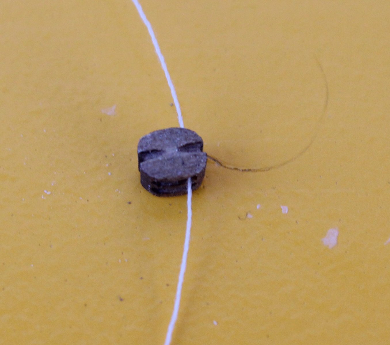
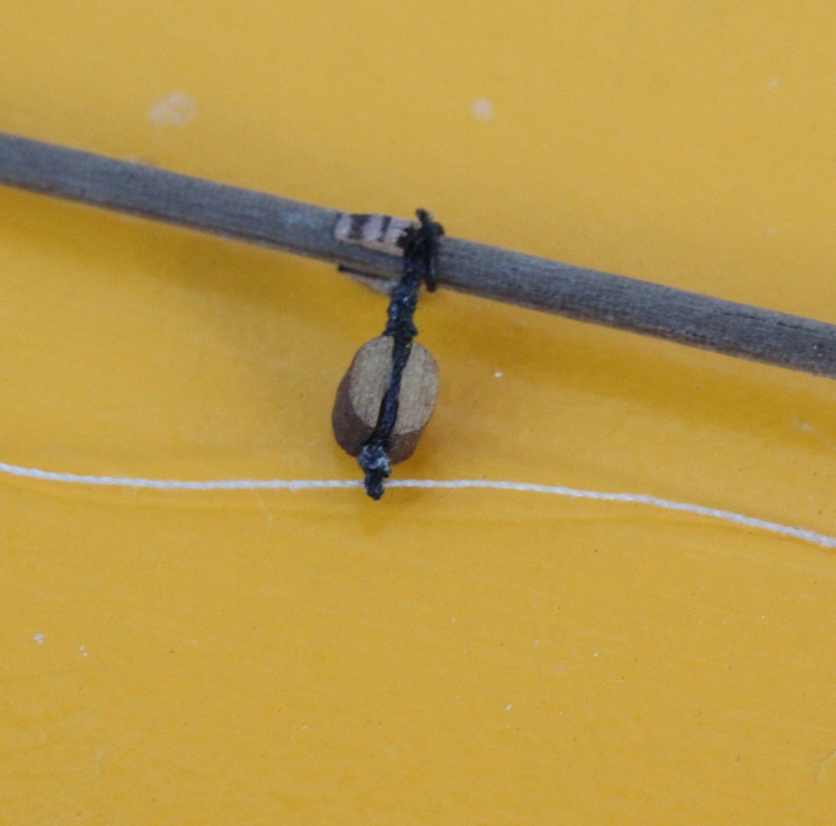
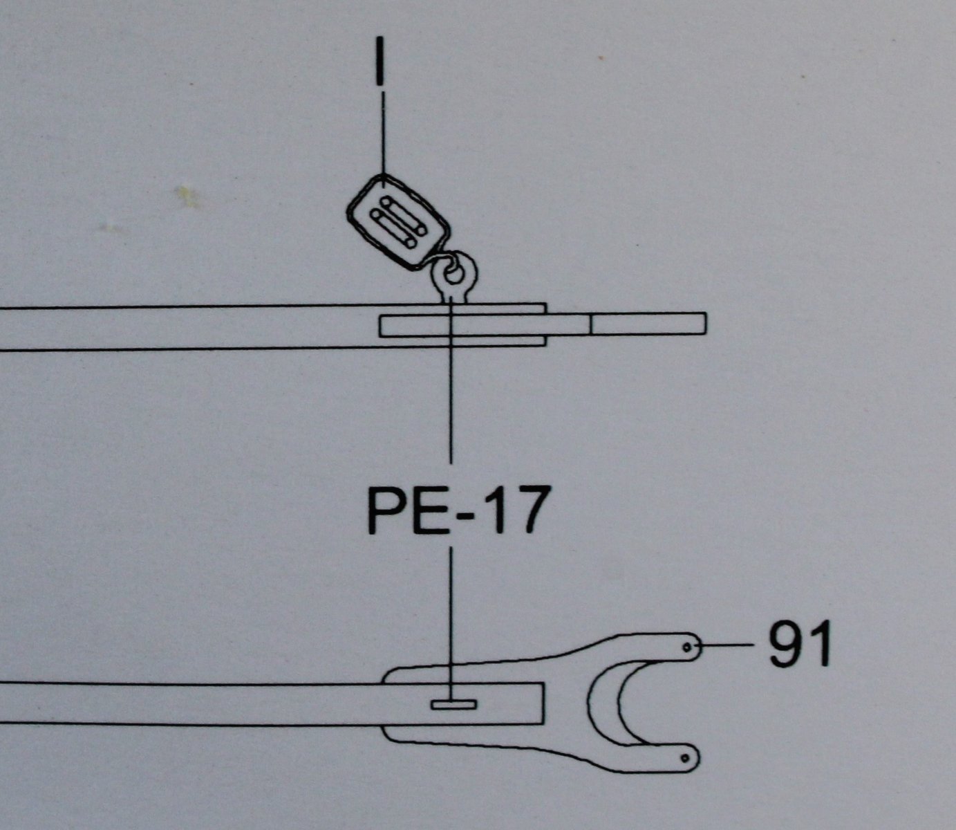
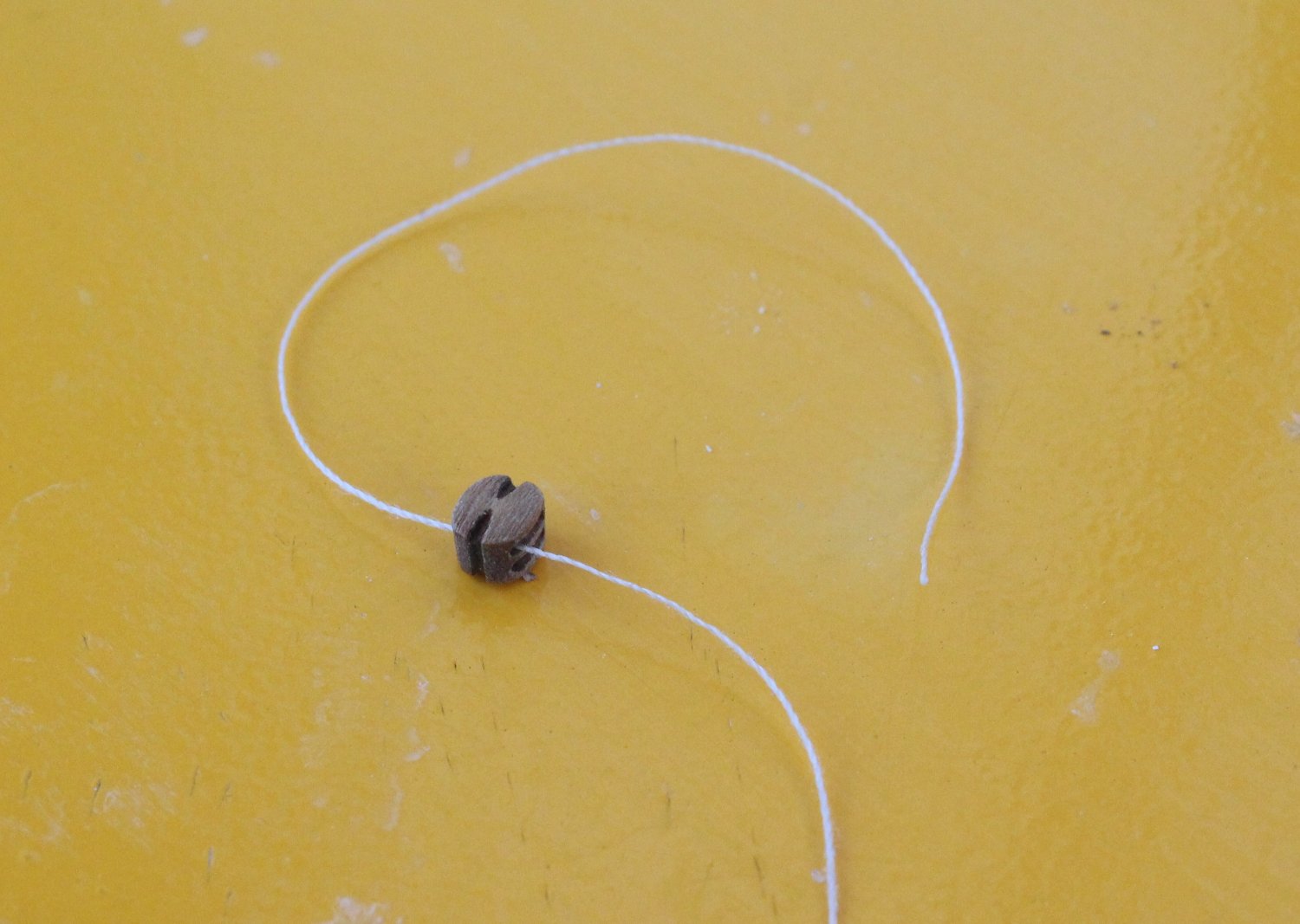
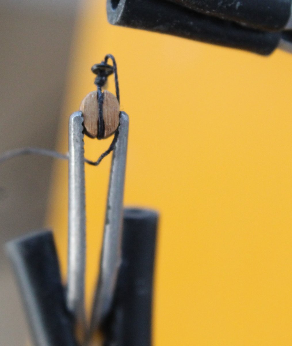
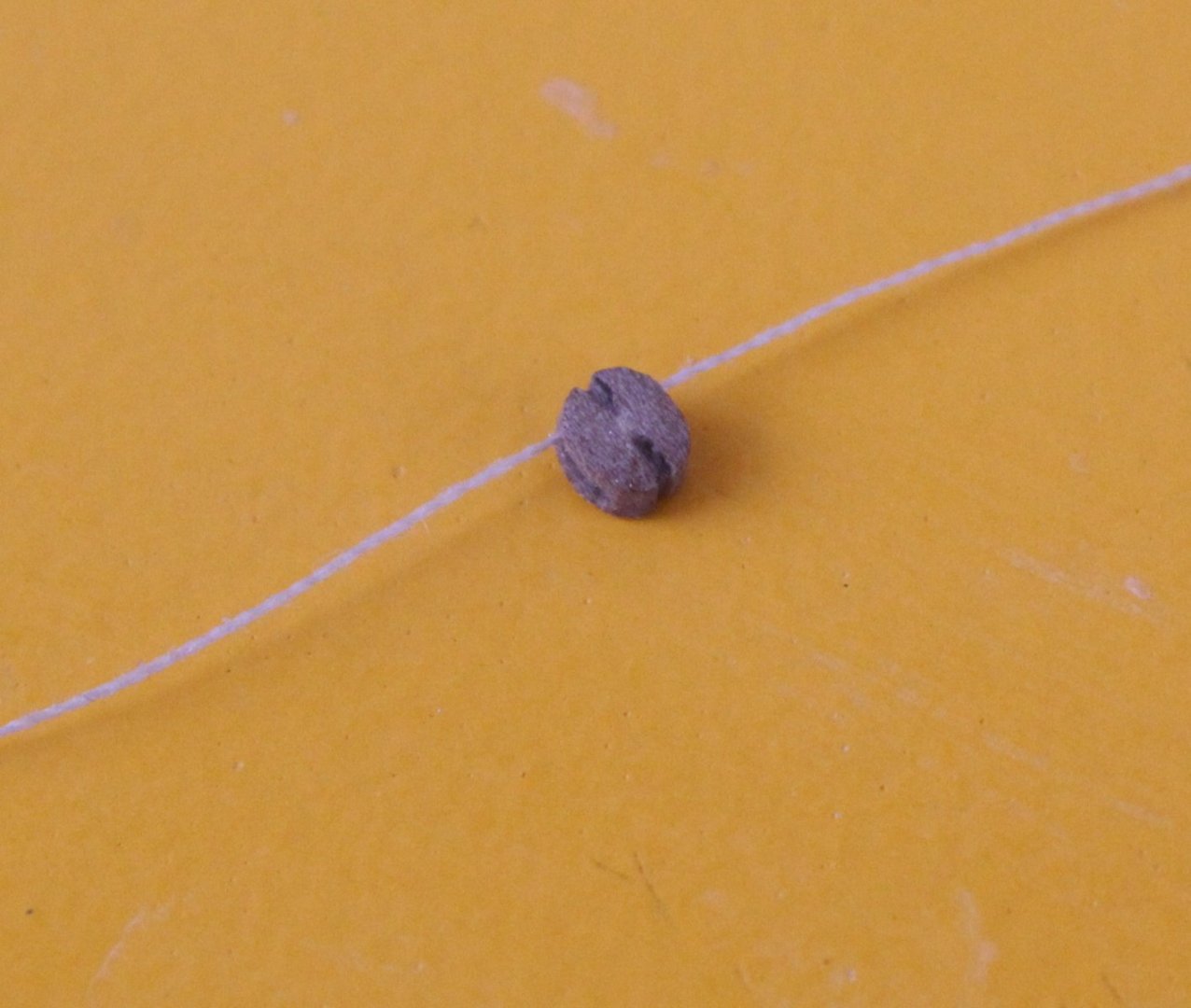
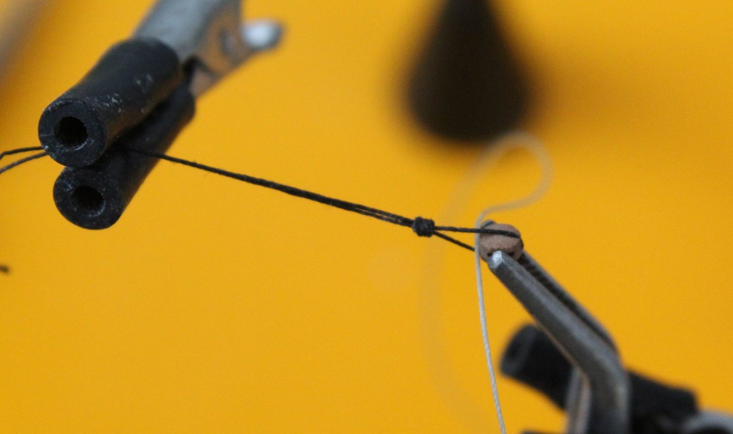
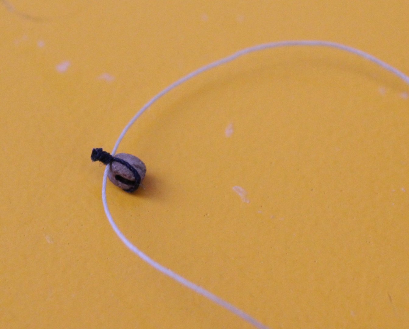
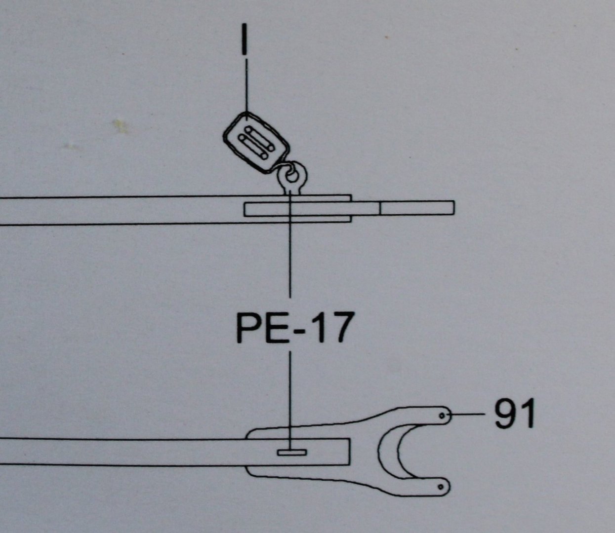
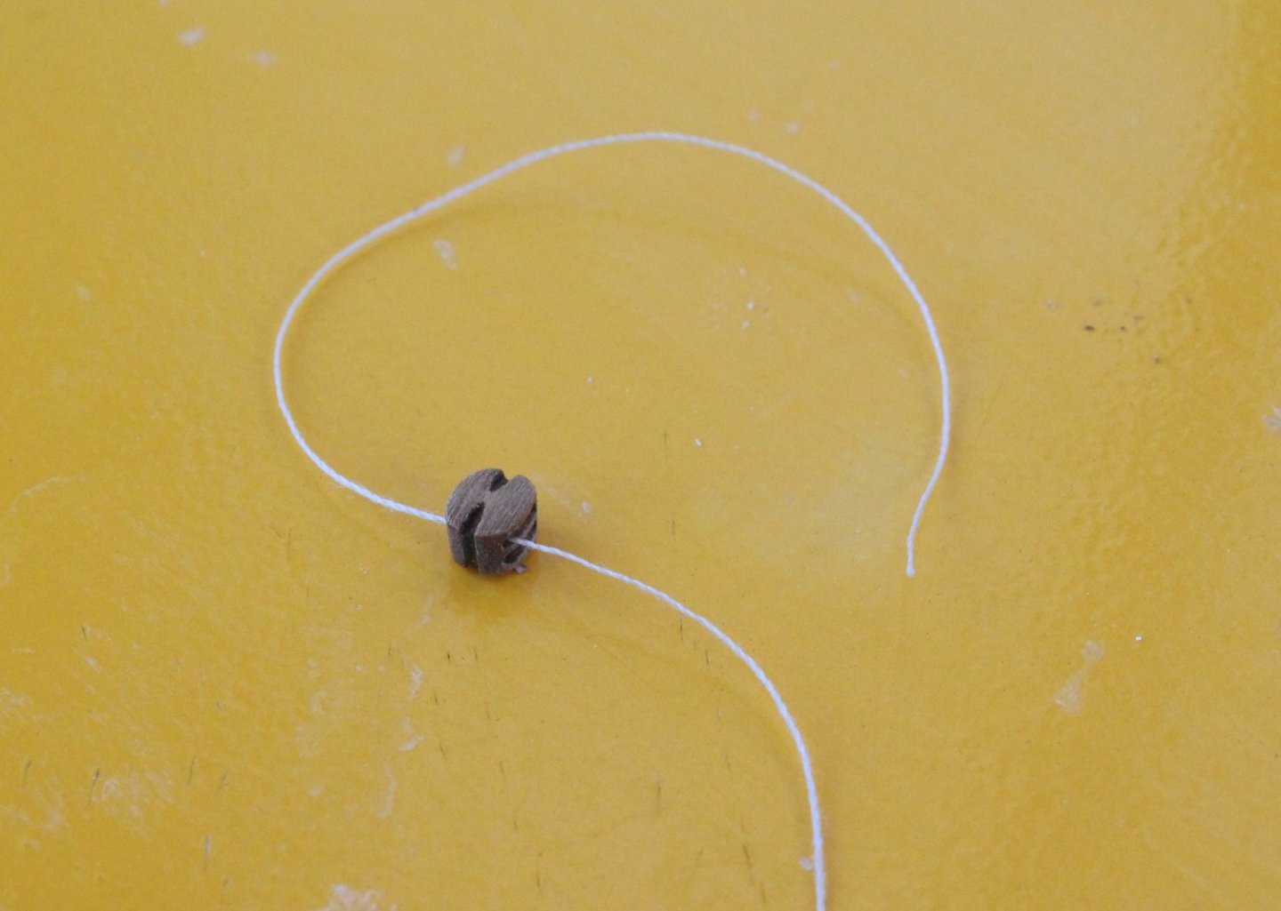
025 - Adding Block to Mizzen Gaff There is an interesting 3mm single block to be added to the mizzen gaff as can be seen in the following photo. After a bit of thinking I decided on a method to install this block on the mizzen gaff which is detailed in this post. The 3mm block is secured to the mizzen gaff in two places, using 0.25mm natural thread which is passed through a thimble on the bottom of the block. Scaling up from the plan sheet I calculated the short length of the 0.25mm natural thread as 8mm and the longer thread length as 14mm. As with all blocks my first task is to check the rigging thread will pass through the block holes. If the rigging thread (0.1mm natural thread for this block) does not I will run a micro drill through the holes. I have found it better, especially for the smaller blocks, to run a micro drill through the block holes after the seizing has been added. The test rigging thread passed through the block so there was no need to enlarge the block holes. I started by seizing some 0.25mm black thread to the block, with the seizing thread being 0.1mm black. The seizing comprised 4 half-hitch knots, 2 on the bottom and 2 on the top. Before the seizing is closed up to the block a length of 0.25 natural thread is placed in the gap as can be seed in the photo below. With the 0.25mm natural thread in place the seizing was pulled up tight to the block. The natural thread can still be slide back and forth as required. It is a simplified version of a block with a thimble. Once again, I am using a clove hotch knot to secure the block to the mizzen gaff. A touch of ca will be applied to the knot. I will also add a little bit of ca to the back of the two cleats before the thread is pushed up against them. The first clove hitch knot has been tied in the photo below, but I have not added the ca as yet. The other end of the 0.25mm natural thread was secured to the mizzen gaff with a clove hitch knot. The block was roughly positioned so there was approx. 8mm on the short length and approx. 14mm on the long length. With the positioning set the clove hitch knot was tightened up and secured with ca. The block is still free to move on over the natural thread which should enable the thread to be set to the right angle when the block rigging is added.

- 106 replies
-
- 3
-
-
- Erycina
- Plymouth Trawler
- (and 3 more)
-
Many thanks, I love my quad hands. I picked up the alternate half hitch seizing method from a post on one of @DelF build logs.
- 106 replies
-
- 2
-
-
- Erycina
- Plymouth Trawler
- (and 3 more)
-
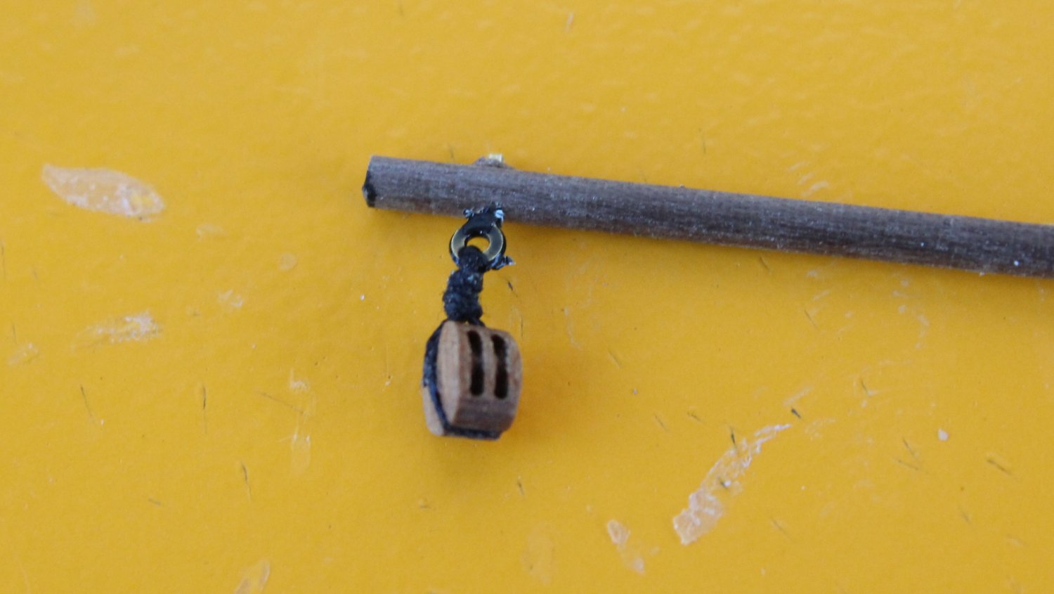
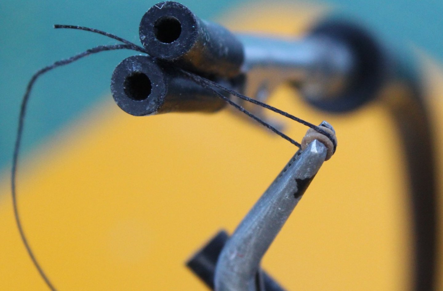
024 - Adding Thimbles and Blocks Part 1 I have detailed methods for seizing and securing thimbles and blocks to masts and yards in some of my previous build logs. To make things simpler I thought it would be better detail some of the methods I use as I add the blocks and thimbles on this build log. The one item which, in my opinion, is a must have for rigging is the quad hands. These are ideal for holding the blocks and thread in place so the seizing can be added. Bowsprit There are two thimbles to be fitted to the end of the bowsprit. The plan sheet indicates that these thimbles should be secured to bowsprit with 0.1mm black thread. I have opted to use 0.25mm black thread. I would have preferred to use fly-tying thread for the seizing as I think it yields a better end result. As I am currently out of stock of fly-tying thread, I decided to use the slightly thicker 0.1mm black thread for the seizing. With the thimble placed in one of the quad hands I cut a length of 0.25mm black thread and wrapped it around the thimble and then placed the two free ends of the thread in one of the other quad hands. The technique I use to add the seizing is to tie a series of half-hitch knots. These knots alternate between the bottom and top. In the picture below I have started to add a half-hitch knot to the top. For the thimbles I added a total of 8 half-hitch knots, 4 to the bottom and 4 to the top. A touch of ca is applied to the final top knot. The two free ends are then released from the quad hands and are pulled in opposite directions which pushes the seizing right up to the thimble. As I will use a clove hitch knot to secure each thimble to the bowsprit therefore one of the free ends needs to be trimmed. After trimming I applied a touch of ca to the cut end to ensure it stays in place. One of the completed thimbles is shown below. Using the clove hitch knots the thimbles were secured to the bowsprit, making sure they were correctly orientated. Mizzen Boom There is one 4mm double block to be added to the mizzen boom. It is an interesting block to seize because it requires a thimble on the bottom of the block as can be seen from the plan sheet. The block will be rigged with 0.1mm natural thread. I like to check the thread will pass through the block before it is rigged, as can be seen below. To start the seizing, I took a length of 0.25mm black thread. A loop was formed and the thread in then held in two quad hands, as shown below. Using alternate bottom and top half-hitch I created the thimble loop. I placed a thin piece of wire in the loop and then pulled the two free ends of the thread in opposite direction to close the loop up around the wire to create the thimble. The 4mm block was then placed in one of the quad hands and the thread was placed around it ensuring the thimble was correctly positioned. Using 0.1mm black thread the seizing was added using 12 half-hitch knots, 6 on the bottom and 6 on the top. With the seizing complete and pulled tight against the block it is now ready to be added to the mizzen boom. One of the free thread ends was trimmed and the block was secured to the mizzen boom using a clove hitch knot. As the knot was pulled tight, I ensure the block was set in the require orientation. I also checked the rigging thread would pass through the thimble Mizzen Gaff There is a 4mm double block secured to the mizzen gaff, via an eyebolt as shown on the plan sheet. I checked that the required rigging thread would pass through the block holes. A length of 0.25mm black thread was seized to the block using 0.1mm black thread with a series of bottom and top half-hitch knots. With the seizing pulled tight to the block one of the free thread ends was then trimmed. An eyebolt was then fed through the remaining thread end. The thread was then placed against the side of the block and held in place with my reverse action tweezers. This is shown in the photo below. Using 0.1mm black thread and a series of alternate bottom and top half-hitch knots another layer of seizing was added. The excess thread ends were trimmed, and the eyebolt was then test fitted to the end of the mizzen gaff, making sure the block was in the correct alignment. The eyebolt will require a bit of trim as it currently poking out of the other side of the mizzen gaff.


- 106 replies
-
- 4
-
-
- Erycina
- Plymouth Trawler
- (and 3 more)
-
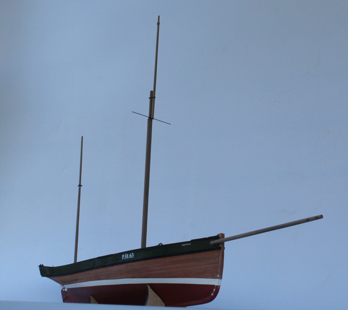
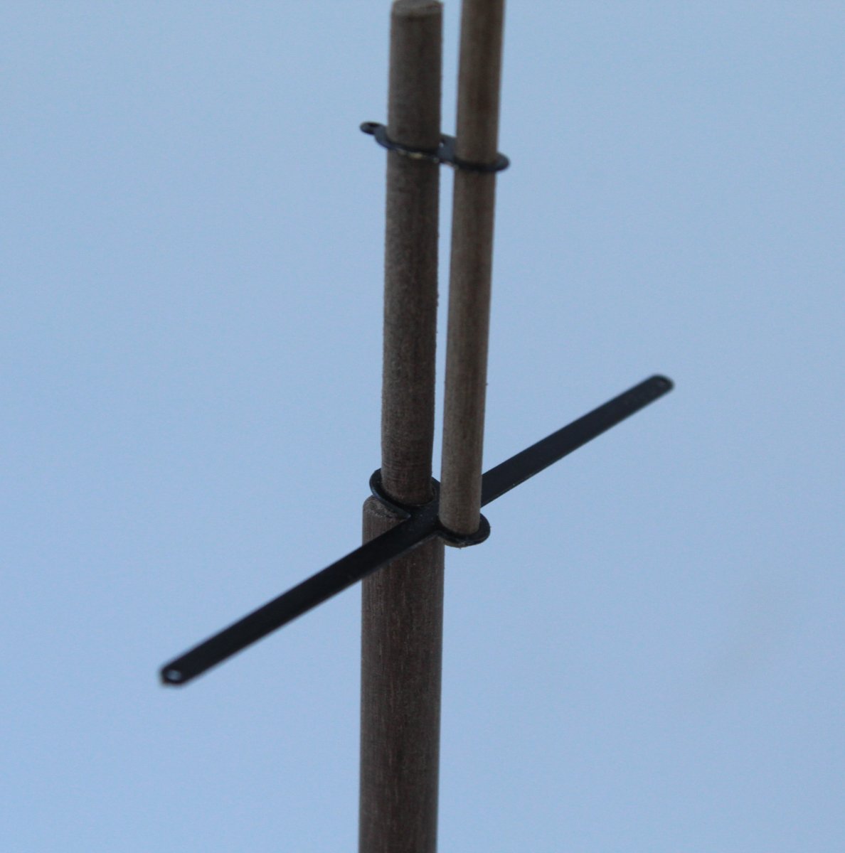
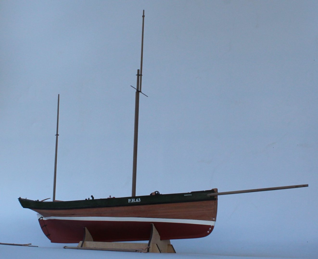
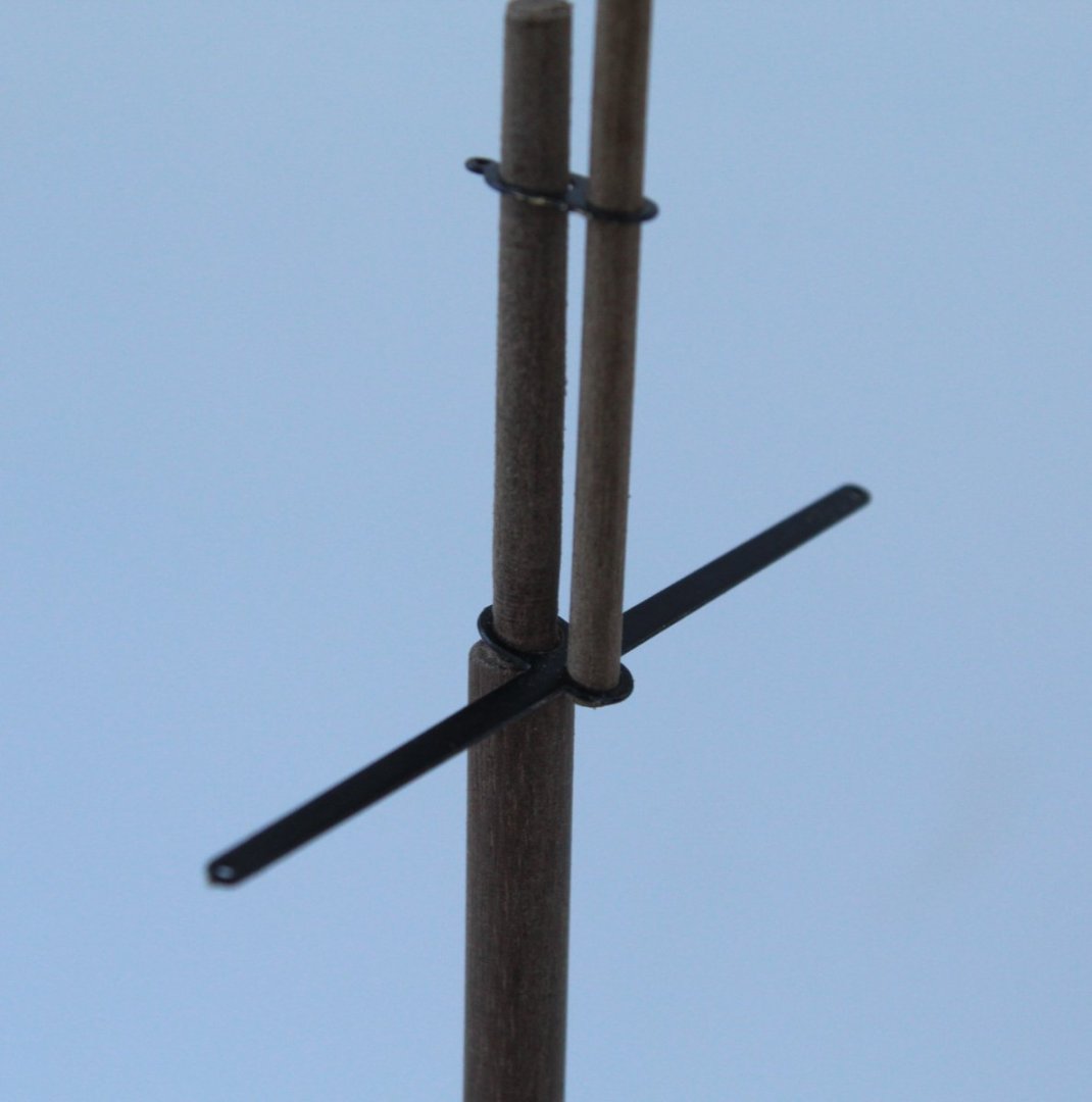
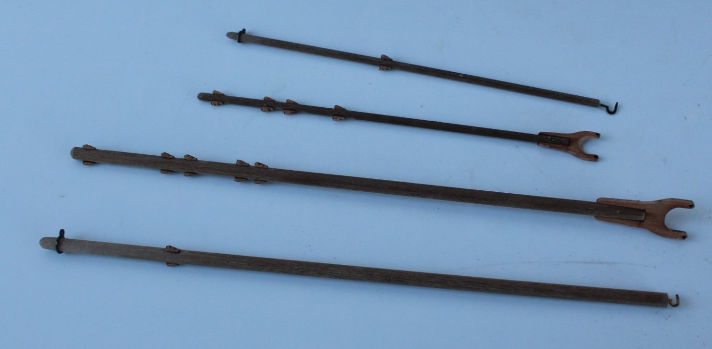
023 - Masts, Bowsprit, Gaffs and Booms I have completed shaping the all the masts, bowsprit, gaffs and booms. The masts and bowsprit have been test fitted as can be seen in the first two photos below. There is a bit more work required before these are finally positioned and secured in place. The opening on the bulwark did require sanding before the bowsprit could be slotted in place. I have also dry fitted the deck ironwork. The main and mizzen mast bases have not been fitted as yet. The ironwork has been test fitted on top of the main mast, a couple of the items can be seen in the photo below. The booms and gaffs have been shaped, the iron work has been test fitted and the cleats glued in place. I am now going to have a fun few days seizing and adding the various blocks to the masts, bowsprit, gaffs and booms. I am using some of my spare pear blocks rather than the kit supplied blocks. I'm also going to spend some time looking over the rigging plans so I can fully understand the various steps. On first glace the rigging associated with the double block fitted in the Main Sheet Chock box looks a bit tricky. The block does rotate which hopefully will make task a bit easier. I have ordered the Erycina deluxe, pre-sewn sail set from Vanguard Models. This is going to be a new challenge as I have not added sails to any of my previous models. I have also ordered some RIT dye power, cocoa brown to colour the sails. I have no experience with dying fabric so again will be another new challenge. I plan to use the free sail set provided with the kit to experiment with the dying process.

- 106 replies
-
- 7
-
-
- Erycina
- Plymouth Trawler
- (and 3 more)
-
Hi Craig I am also building Saucy Jack as a background task, which is ready for the first planking. These two fishing boats are a stop gap project after I completed the Sphinx and before the release of the Indy, which will be my next major project. I built the Alert as a stop gap project after I completed the Duchess of Kingston before the release of the Sphinx.
-
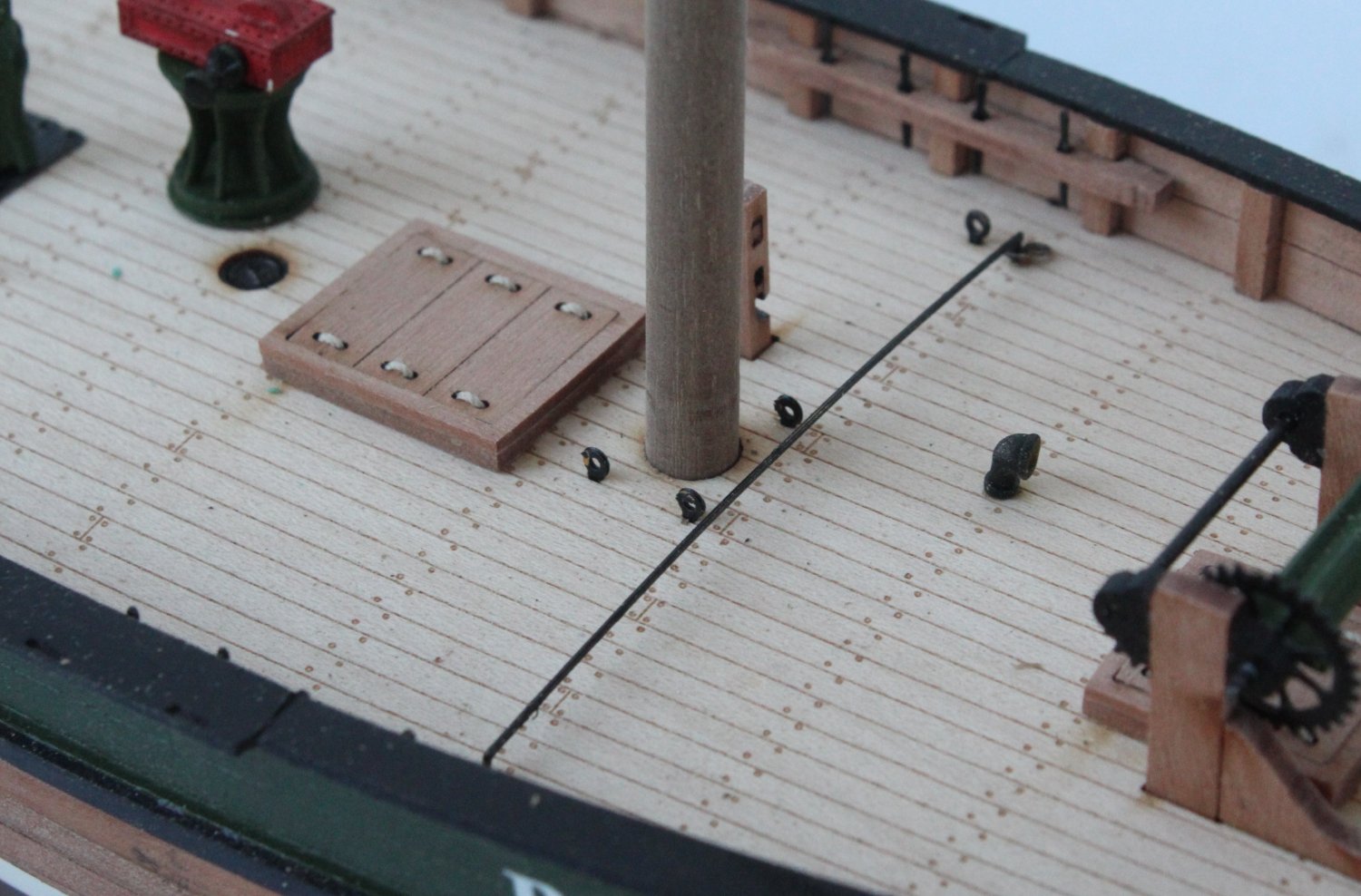
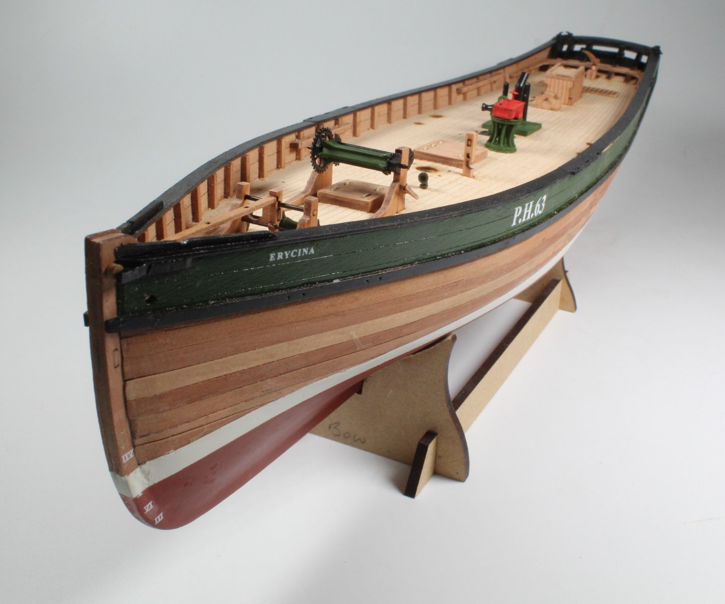
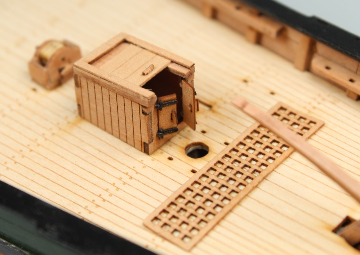
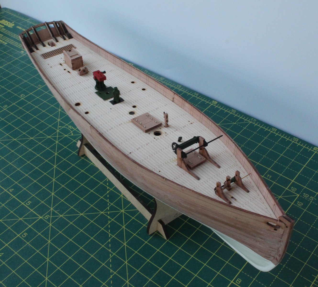
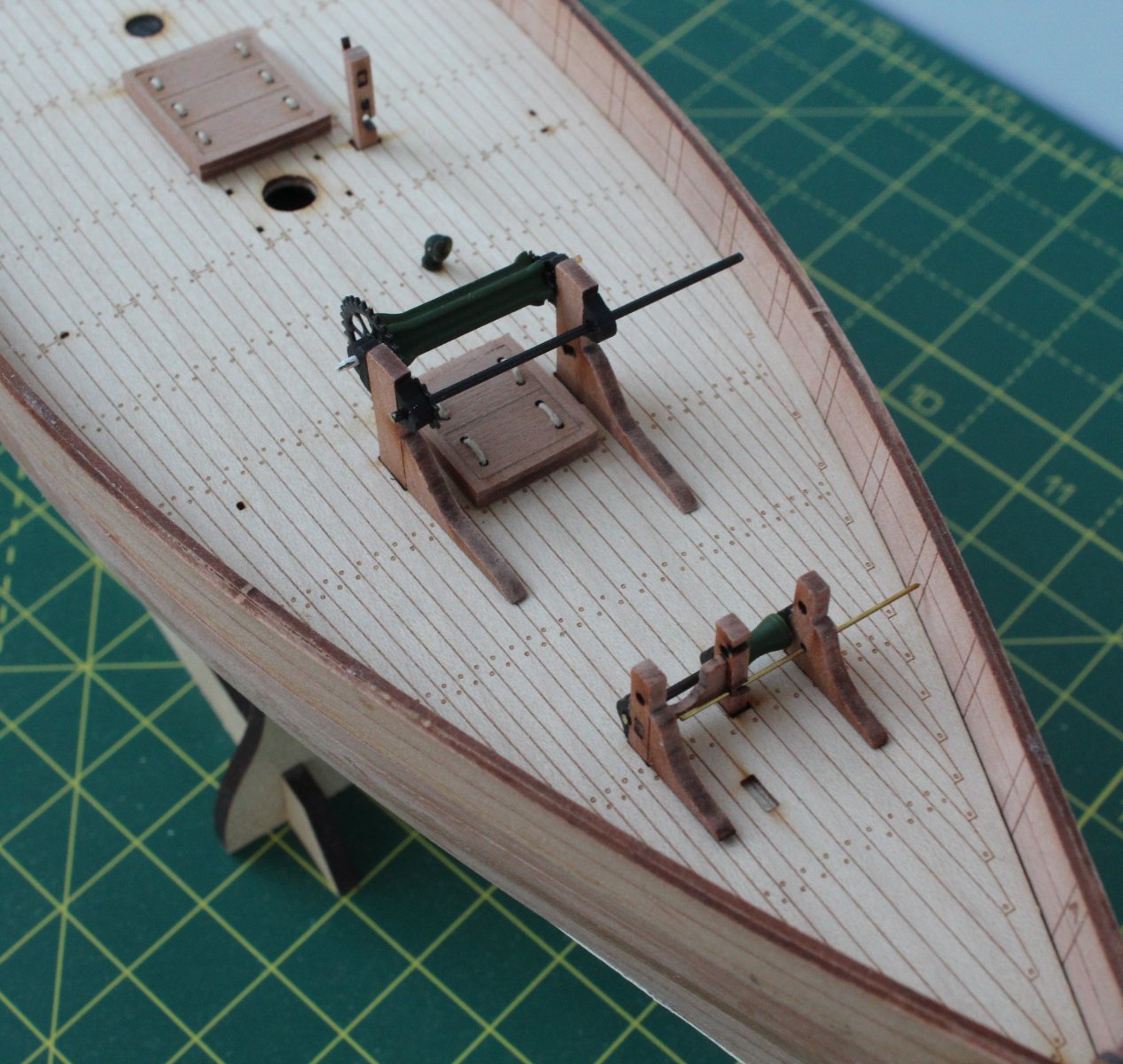
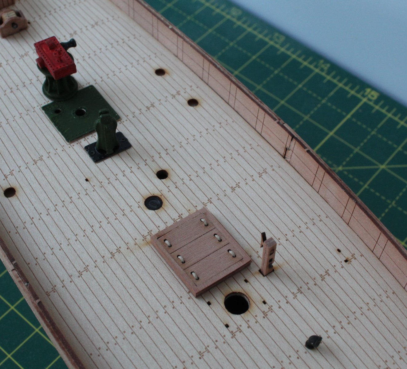
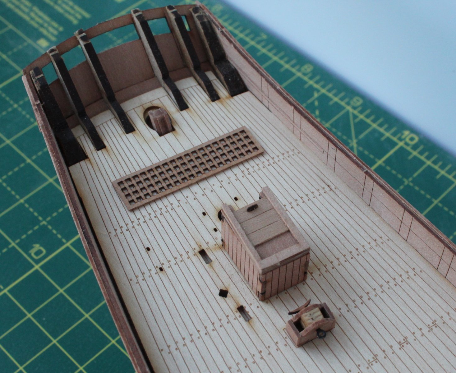
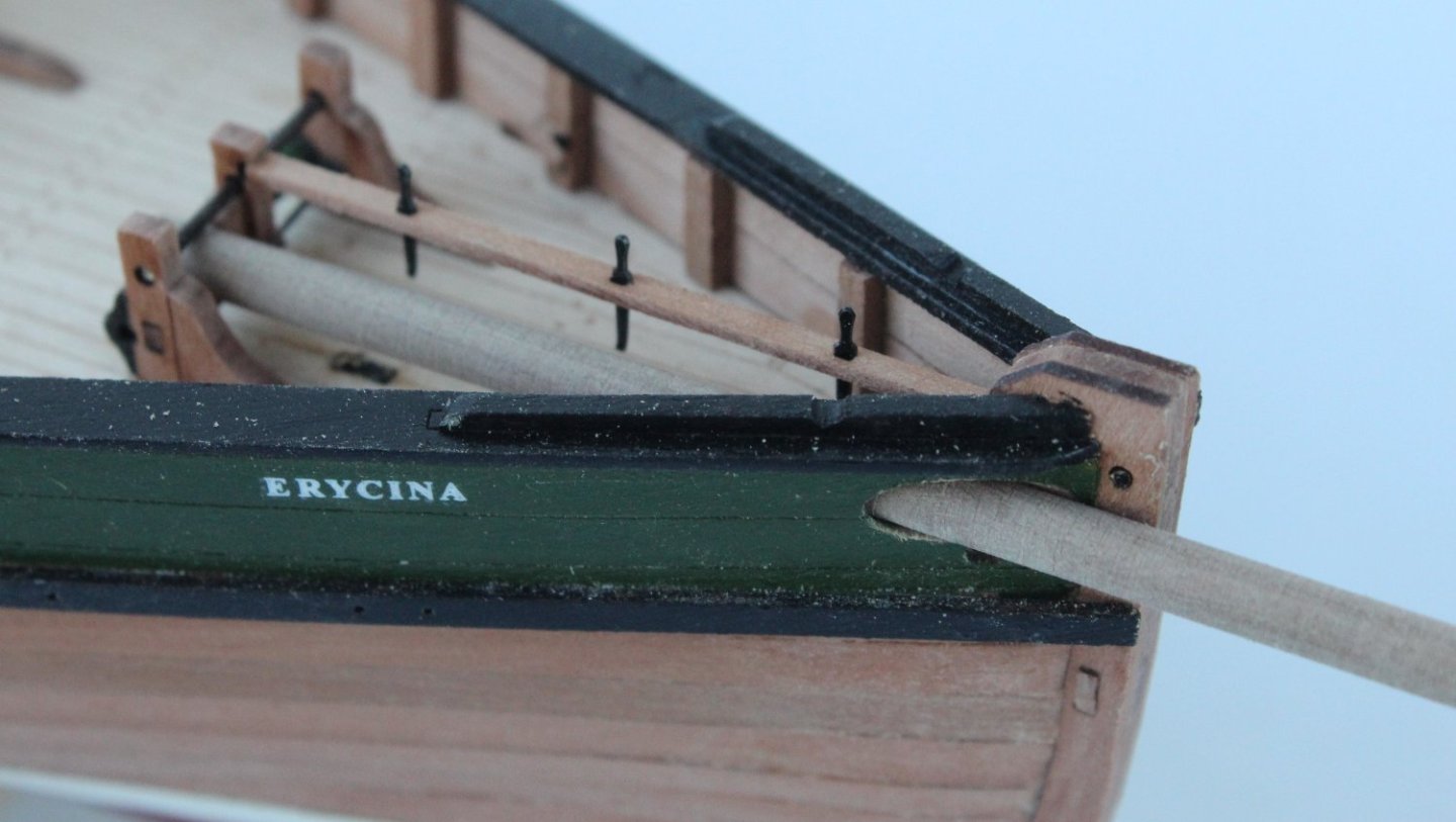
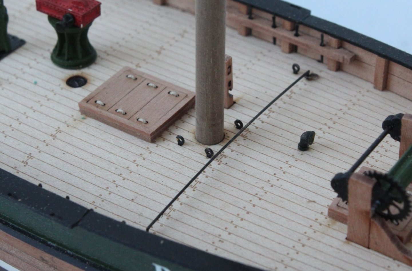
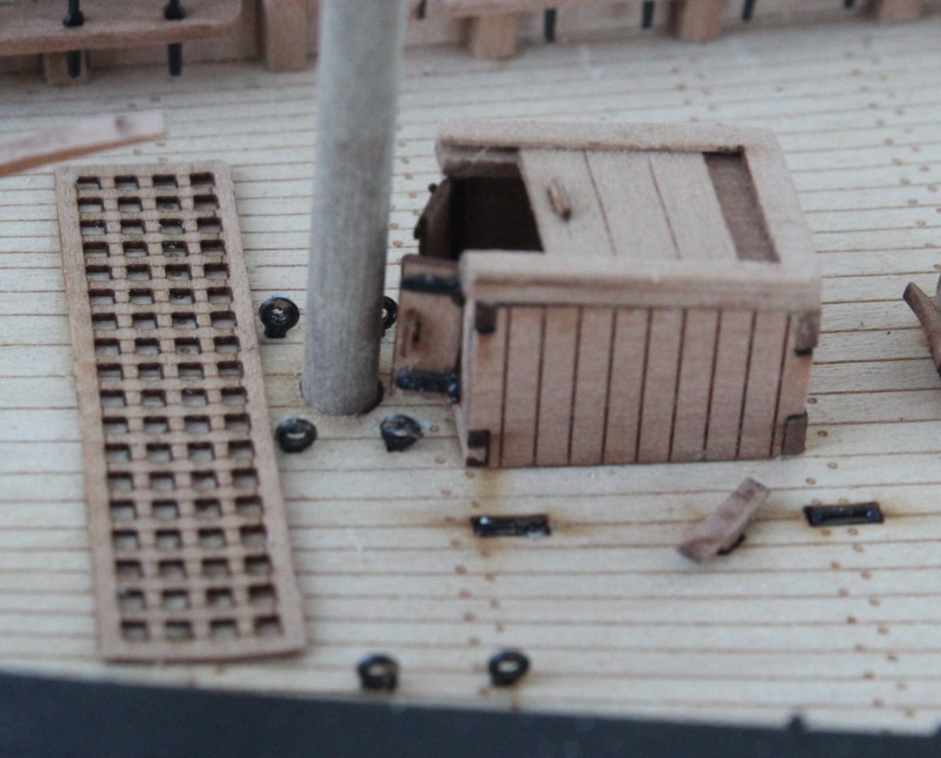
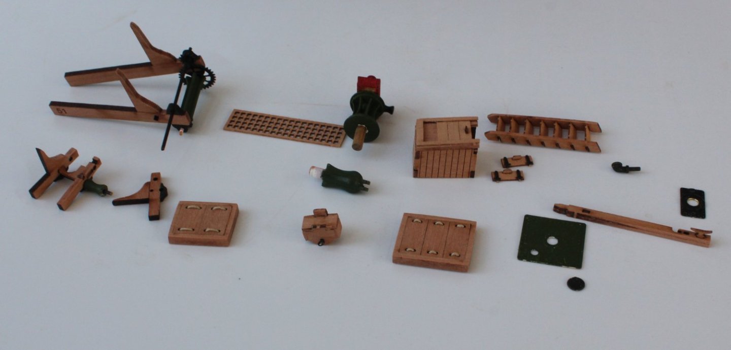
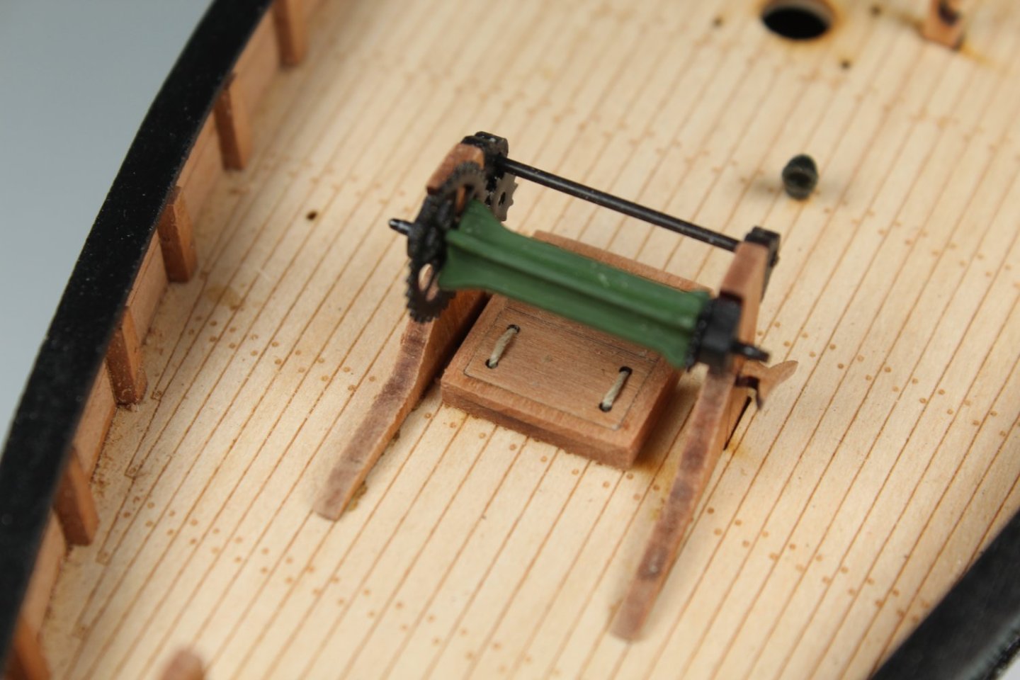
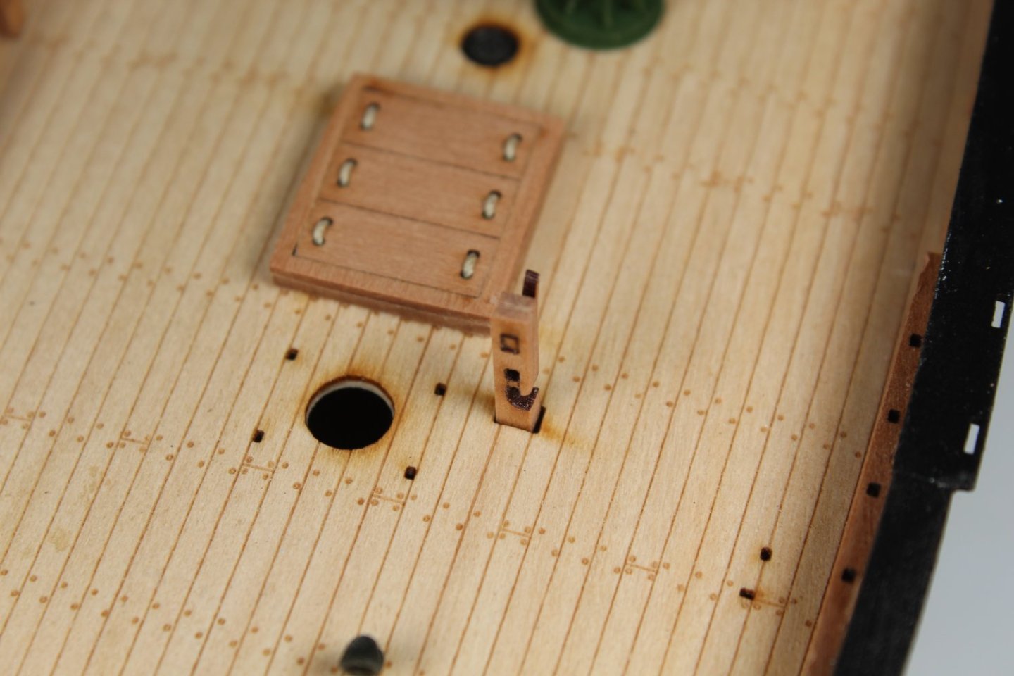
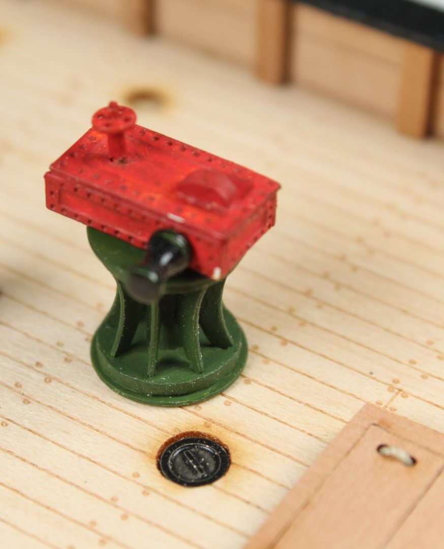
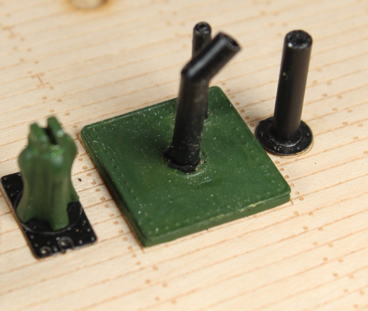
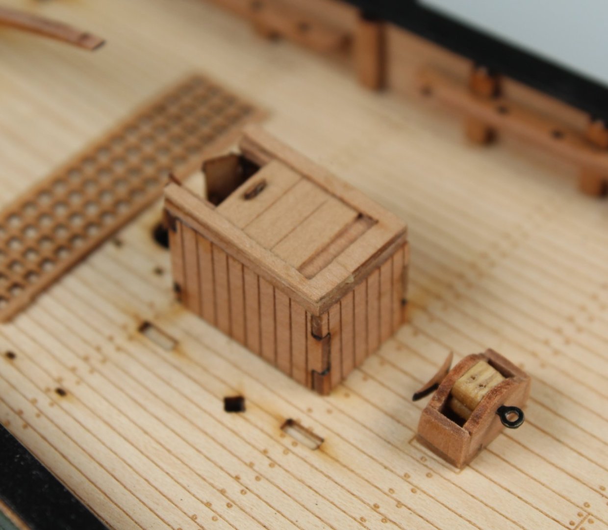
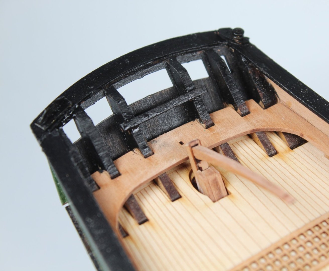
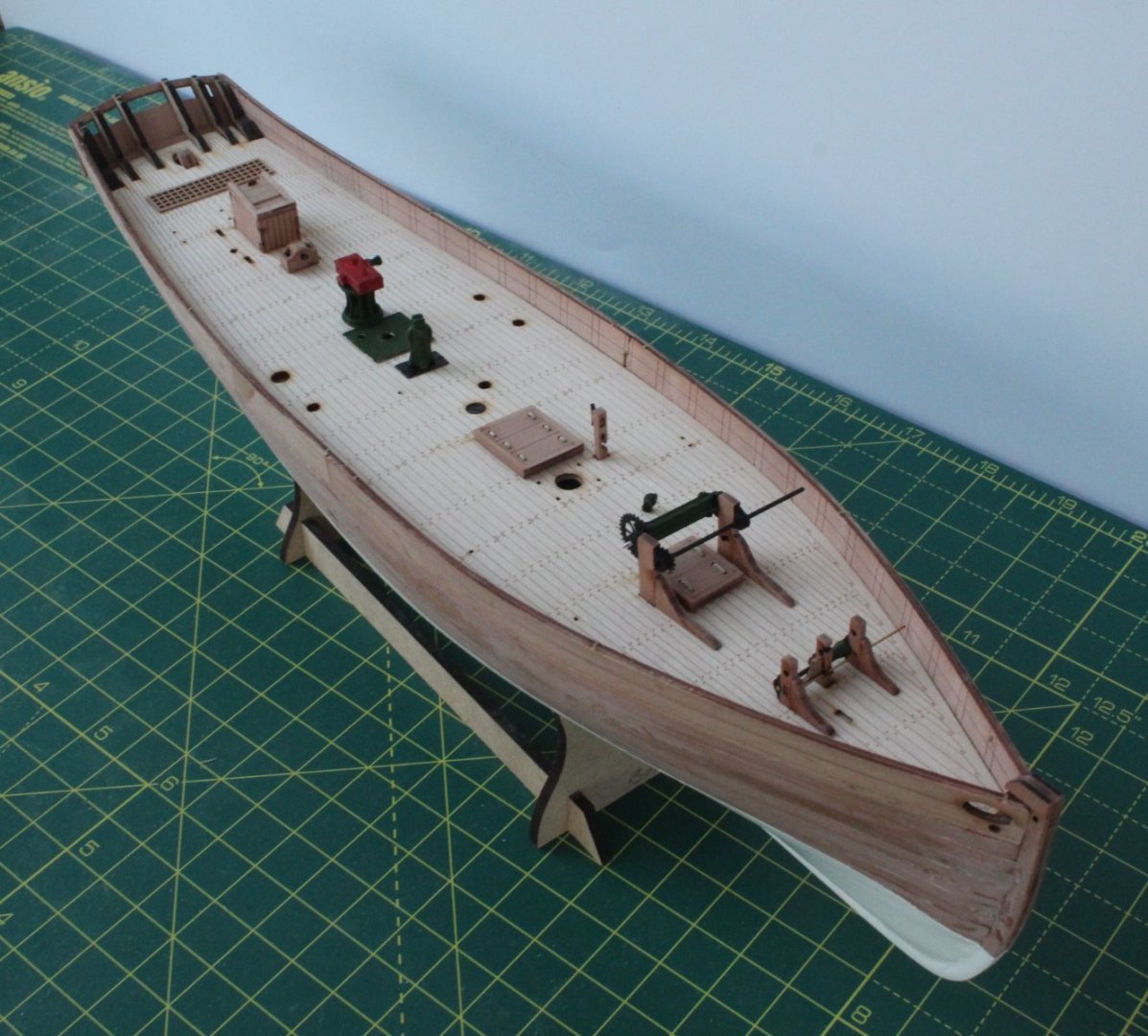
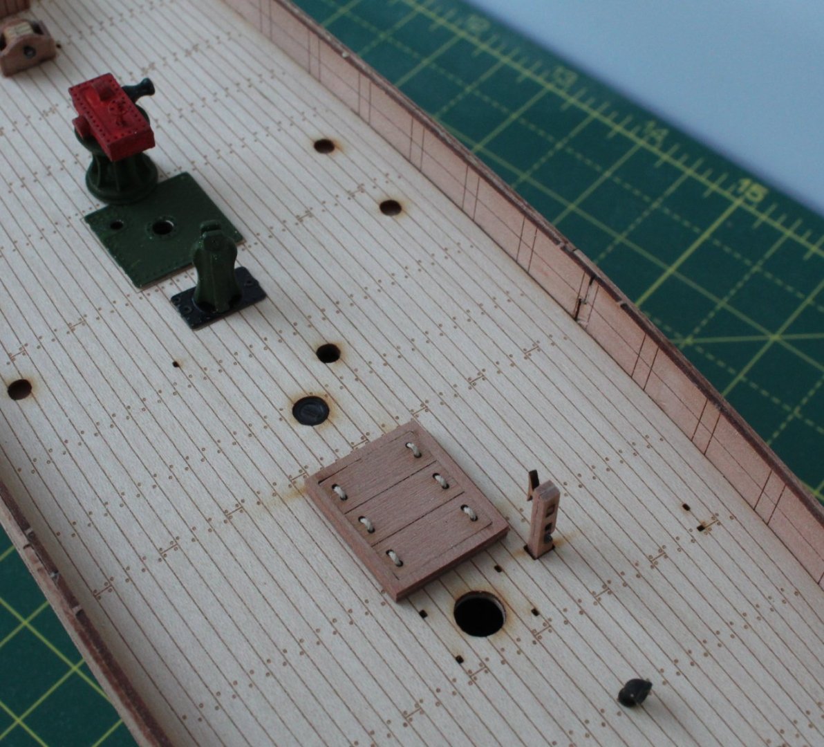
022 - Adding The Deck Items I painted the gunwales black and then fitted them to the top of the bulwarks. I also painted the upper rear section of the stern area black. With the gunwales glued in place I am now ready to add the previously assembled deck items. The various deck items were then added to the deck. And now a few close ups of the various deck items. You will note I have not fitted the various eyebolts, belaying pins or cleats. I normally like to fit these once I have studied the rigging plans as I have found that it is sometimes easier to seize some of the rigging to the eyebolts before they are fitted. Tomorrow, I plan to start work on the masts, yards and bowsprit.


- 106 replies
-
- 6
-
-

-
- Erycina
- Plymouth Trawler
- (and 3 more)
-
005 - Adding the bulwark patterns I am not making too much progress on this build at the moment as I am pressing on with the Erycina build. All I have done to the Saucy jack is to add the two bulwark patterns. I did soak and bend the patterns to shape before gluing in place. I think this was a mistake as I did end up with some unwanted curling of the patterns. Thankfully I was able to correct this. The Saucy Jack is now ready and waiting for the first layer of planking.


- 62 replies
-
- 7
-
-
- Saucy Jack
- vanguard models
- (and 3 more)
-
Congratulations, you have built and wonderful model
- 73 replies
-
- 1
-
-
- Sphinx
- Vanguard Models
- (and 1 more)
-
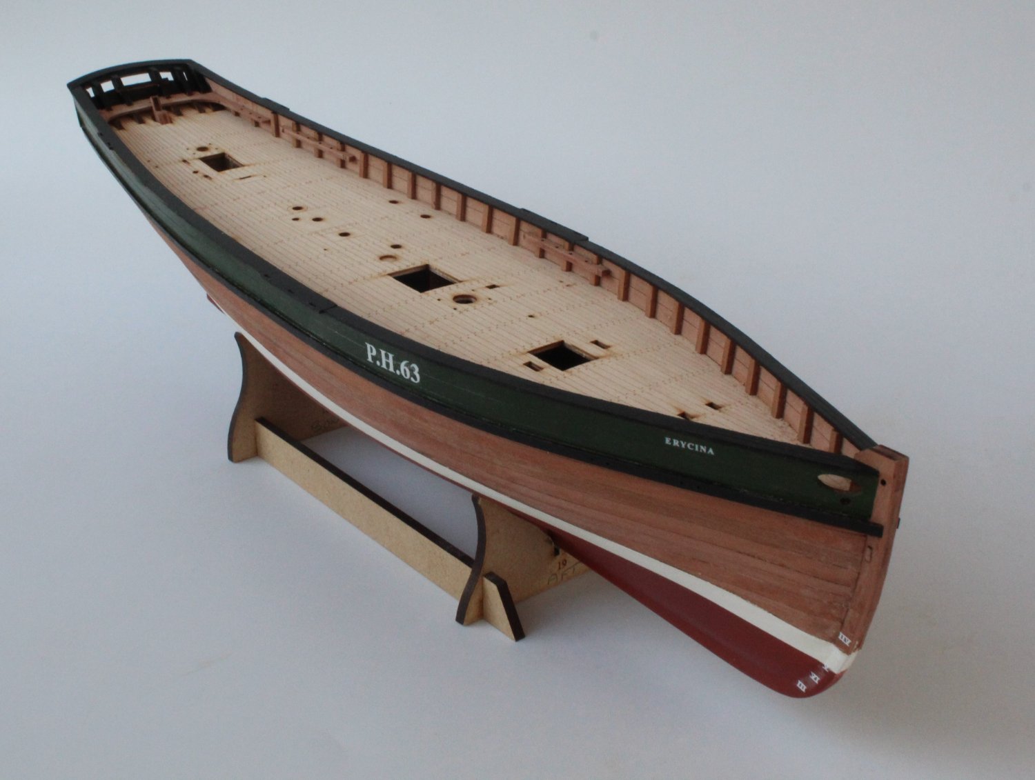
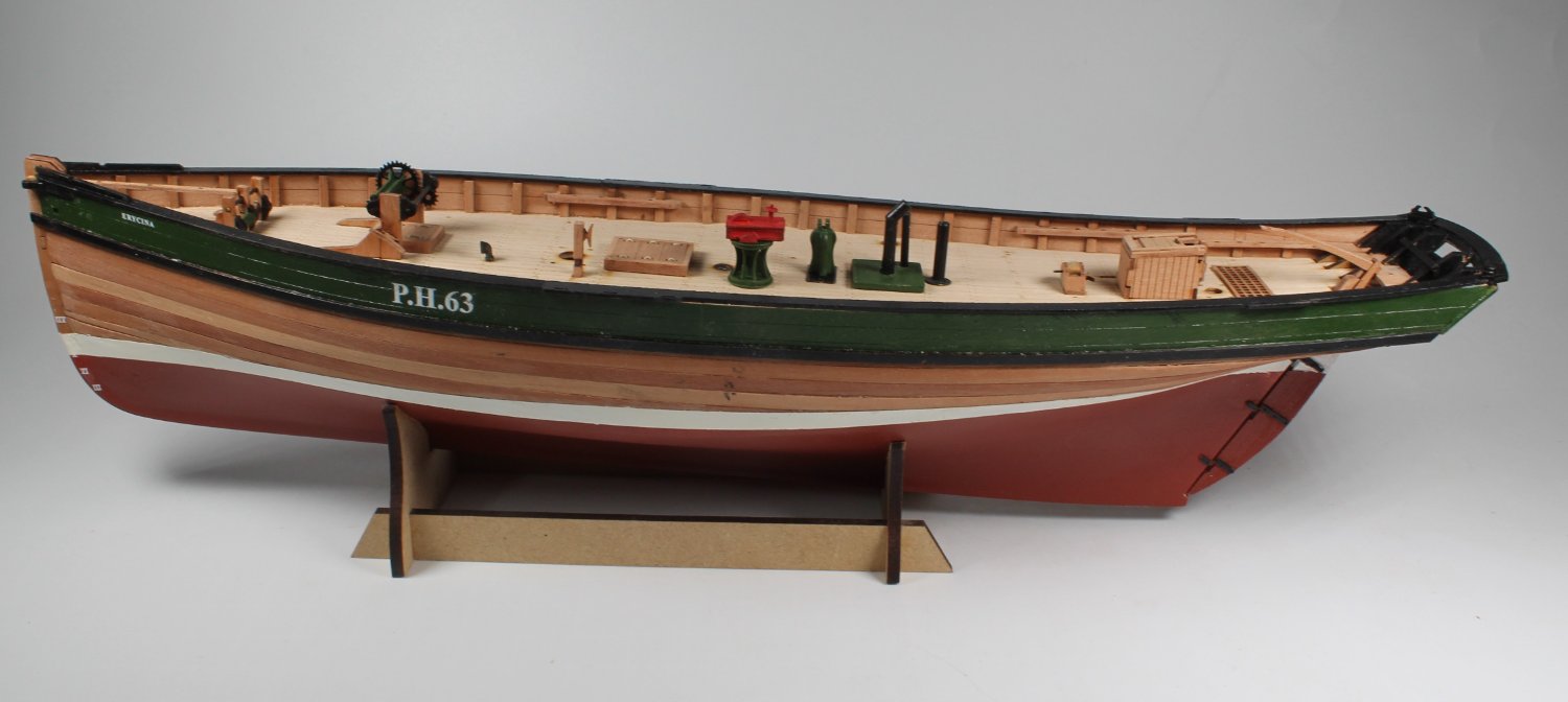
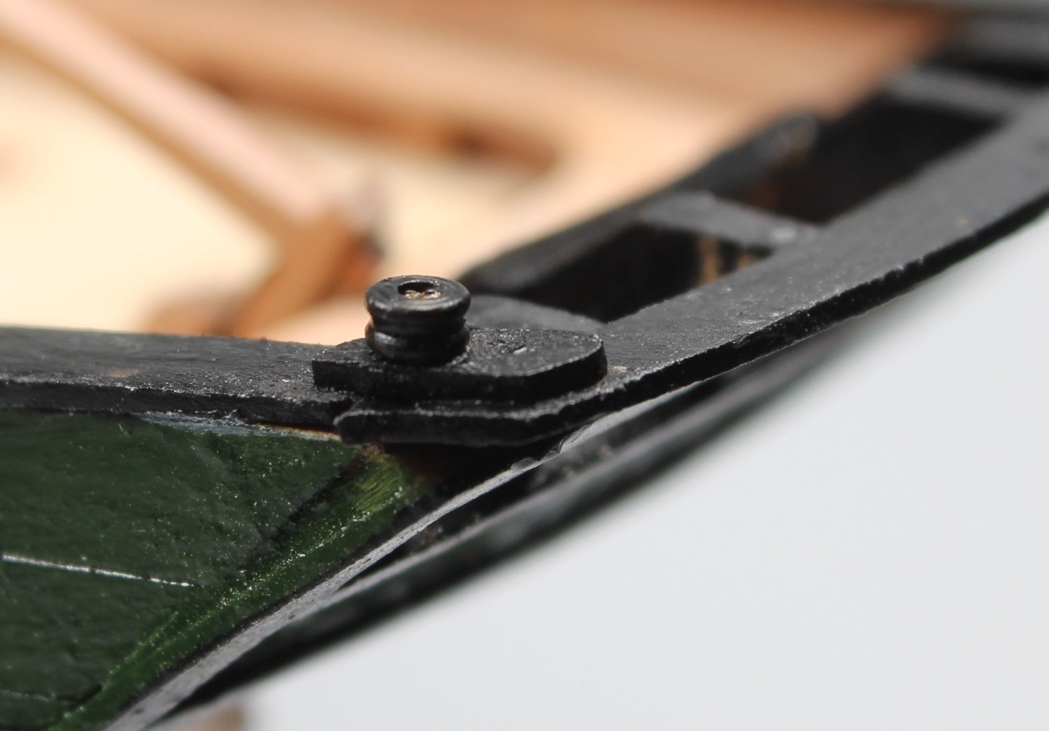
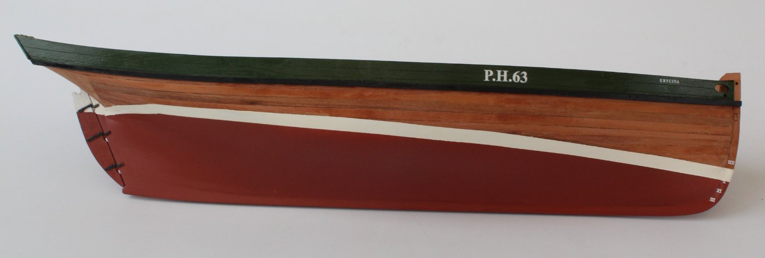
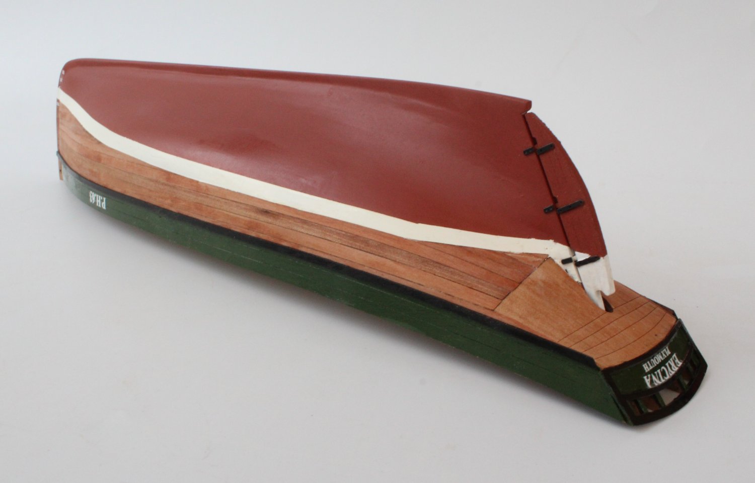
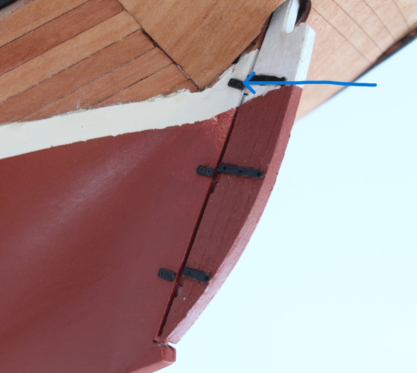
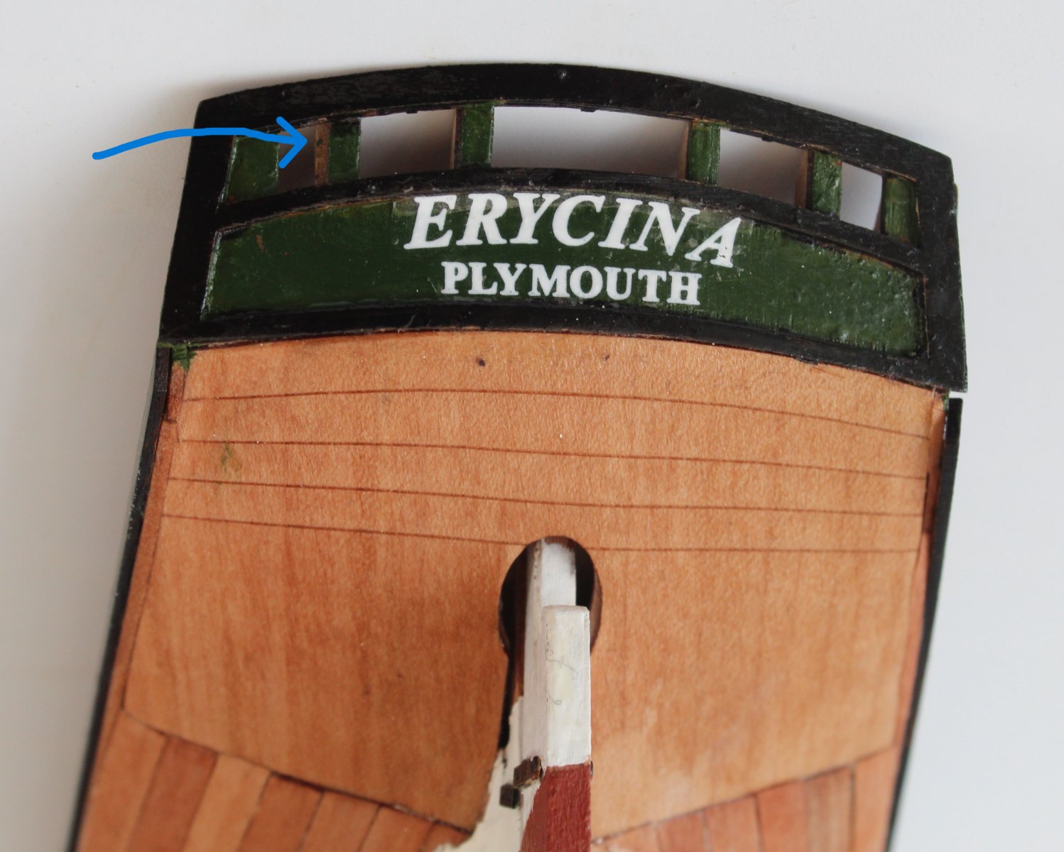
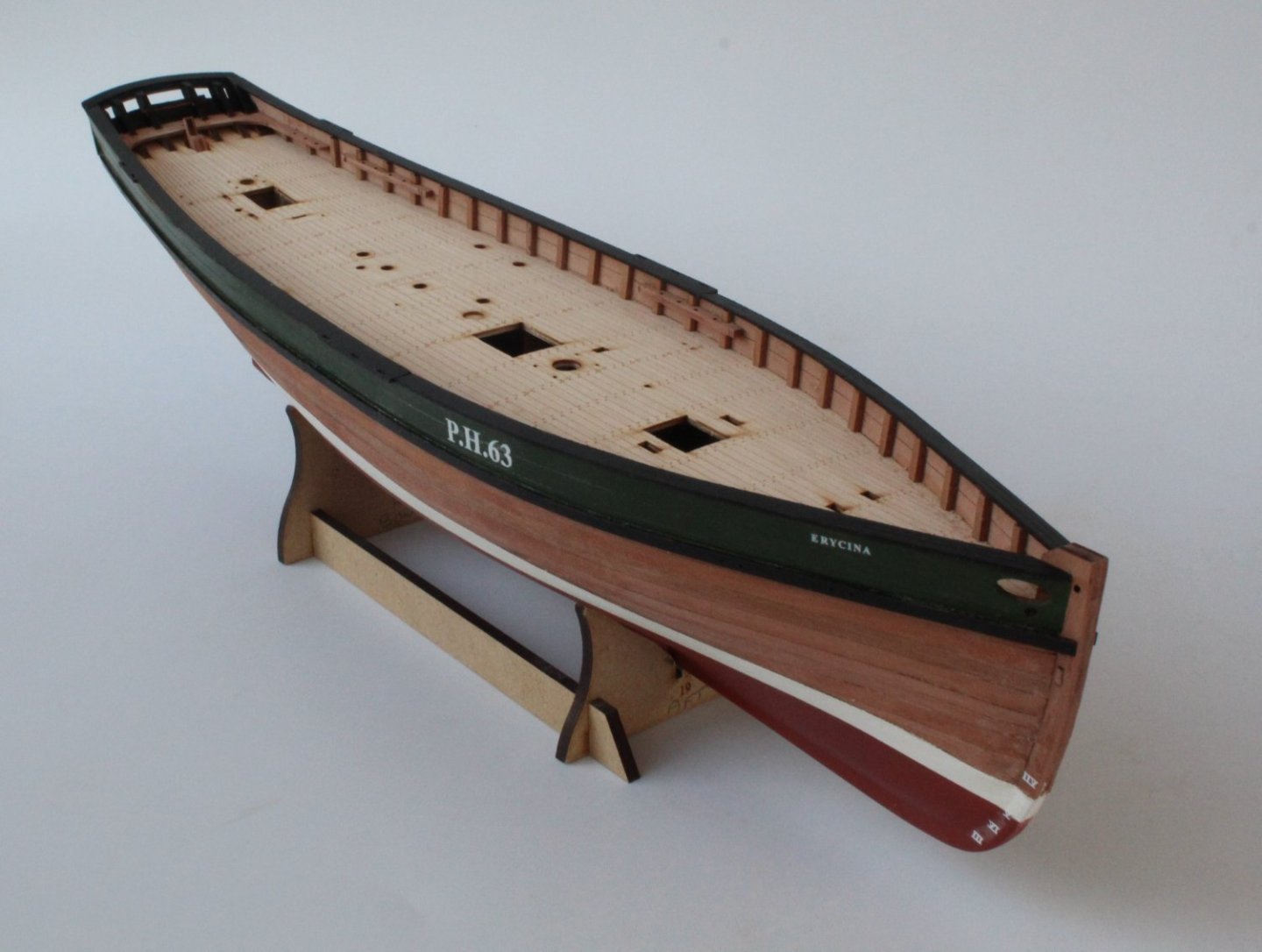
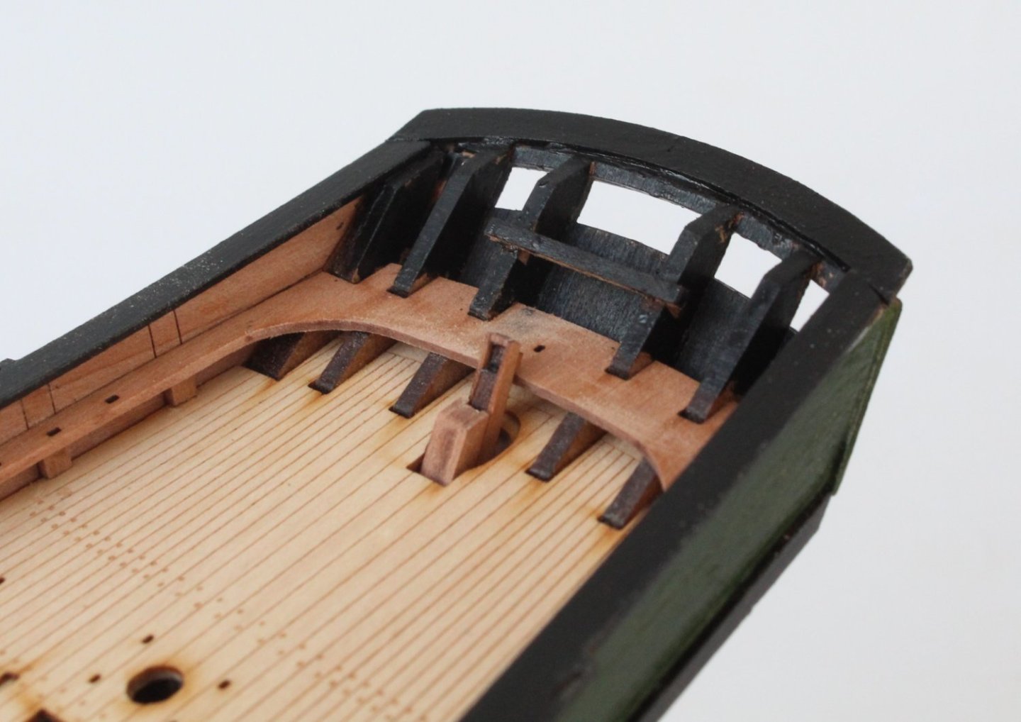
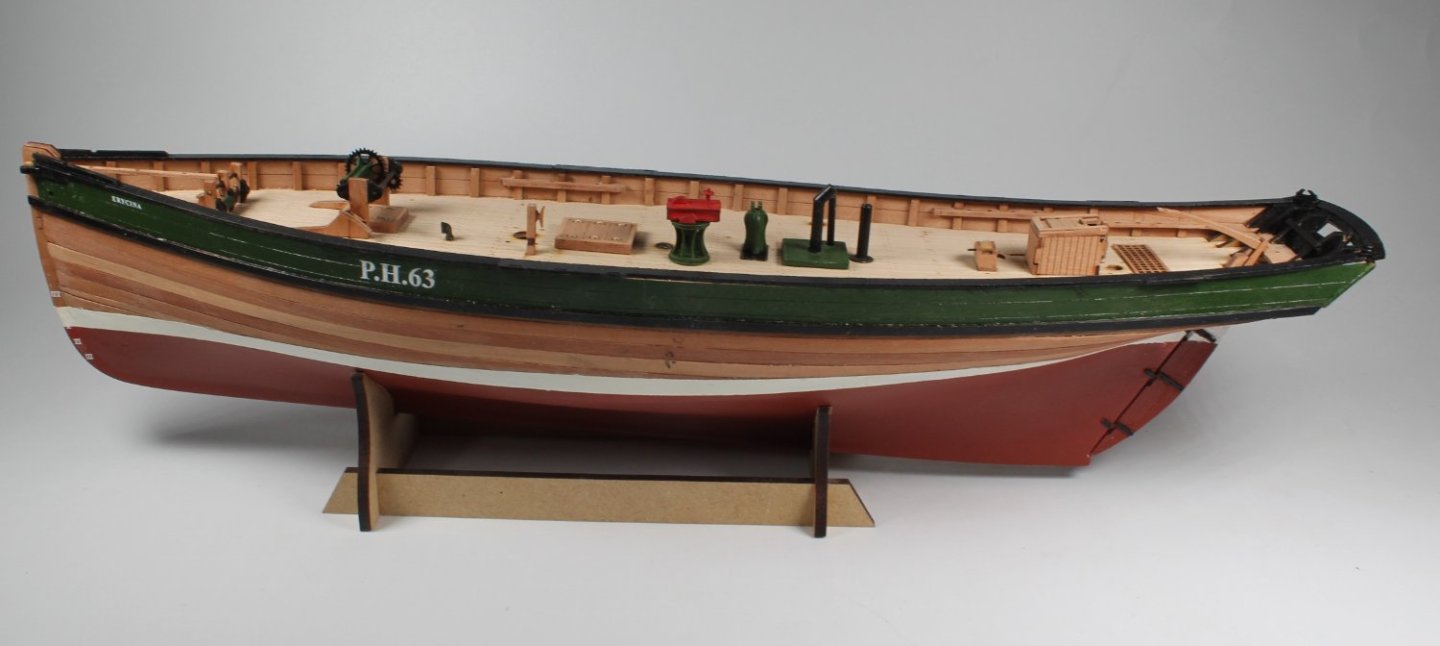
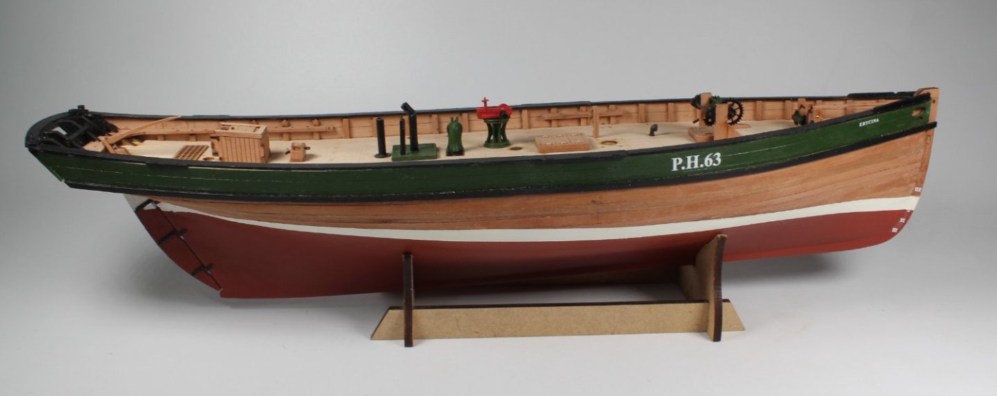
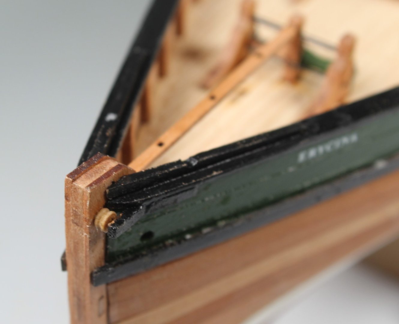
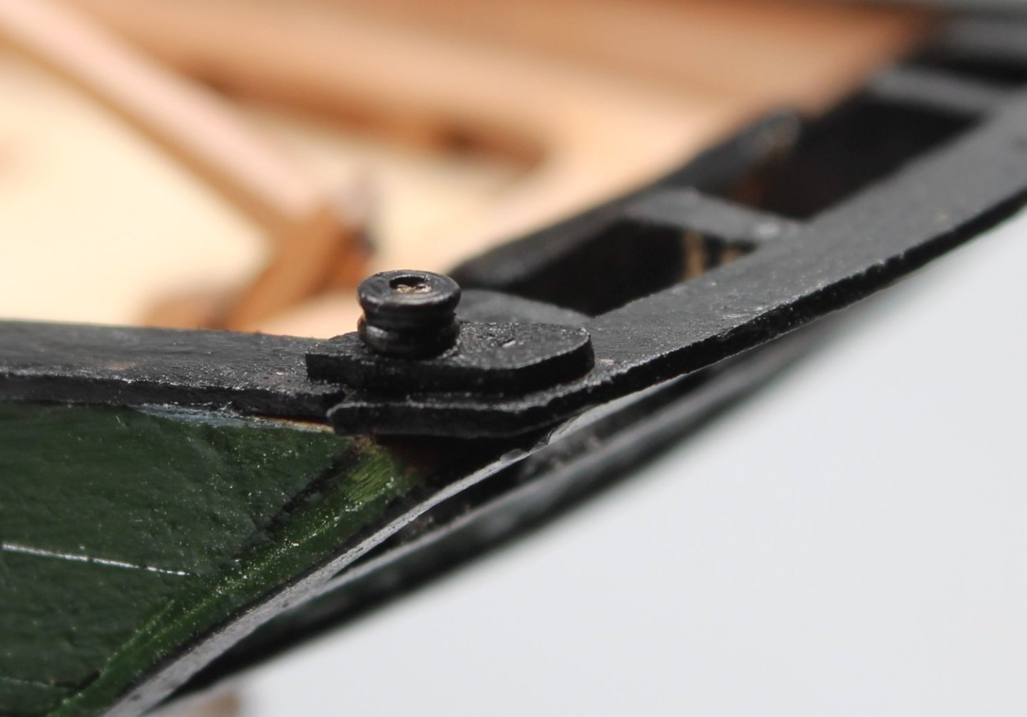
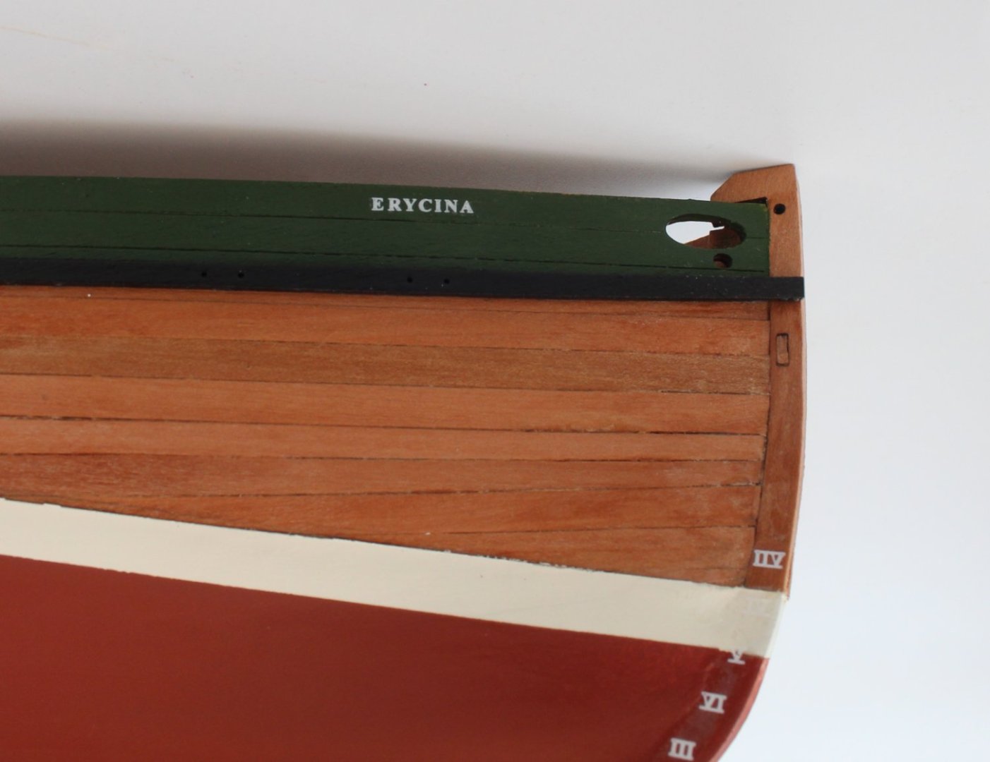
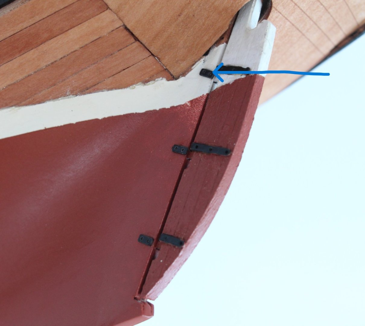
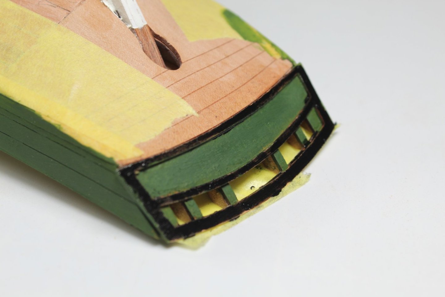
021 - Hull Painted, Decals and Rudder I have now completed painting the hull. I have also added the decals and rudder assembly. As can be seen with the close-up photo's there are one or two very small areas where the lines are not clean, mainly around the stern area. For the most part the finished paint job is to an acceptable standard and is more than good enough for me and my low standards. When adding the rudder straps to the rudder post one strap was not positioned as it should be, as shown in the photo below. I could release the part and reposition but, based on past experience, this may damage the paint. It will be left as is. The unclean painted lines are also noticeable with this close up photo. When looking at the rear of the Erycina, the back of the left-hand middle stern frame can be seen. I will just give it a couple coats of paint and I suspect I will be the only person to know about it. The misalignment of the left-hand side upper rudder post strap is also very noticeable in this photo.


- 106 replies
-
- 1
-
-
- Erycina
- Plymouth Trawler
- (and 3 more)
-
I was not intending to do as much work on the Saucy Jack, but the painting phase of the Erycina means I have some free time at the moment. Also having plenty of free time is one of the joys of retirement, although my wife and I are looking after our youngest Grandson (18months old) so there will be little or no shipyard time this weekend.
- 62 replies
-
- 2
-
-
- Saucy Jack
- vanguard models
- (and 3 more)
-
I agree, taking good photos of the rigging is very hard to do. I normally end up rejecting the vast majority of rigging photos I take.
- 118 replies
-
- 4
-
-
- Duchess Of Kingston
- Finished
- (and 1 more)
-
004 - Hull Fairing With the stern counter frame and frame patterns (lower, middle and upper) fitted I spent some time fairing the hull, using a mixture of florey sanding sticks, 120 grit sandpaper and my Amati sanding block. I am reasonably happy with how the hull looks. I will now spend some time checking how various planks will lay to make certain the fairing process is complete, especially around the stern area.


- 62 replies
-
- 5
-
-
- Saucy Jack
- vanguard models
- (and 3 more)
-
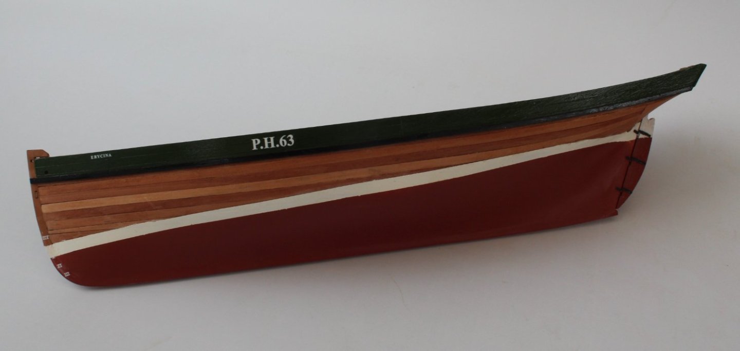
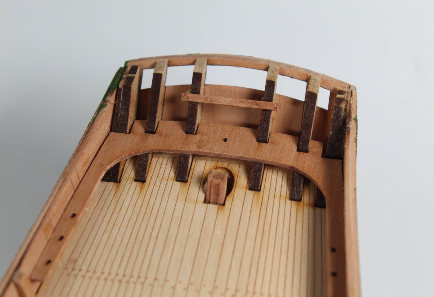
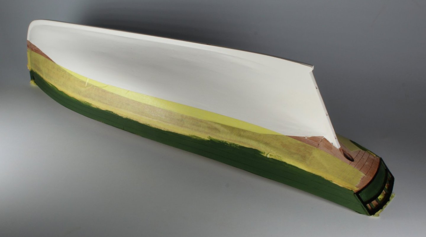
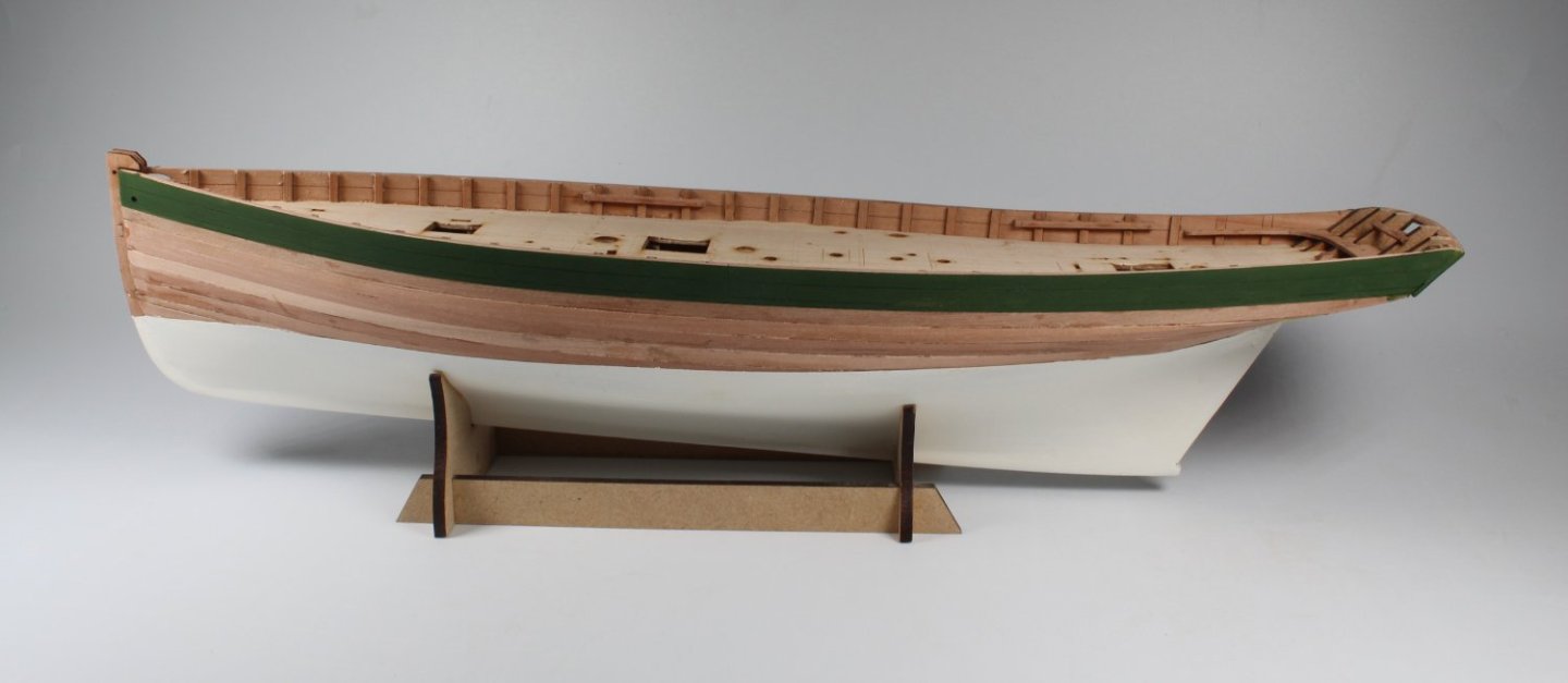
020 - Timberheads and Paint I have made a bit more progress today. Starting with the right-hand side the first 'A' timberhead was removed from the sheet. After the laser char had been removed and the bottom edge shaped as necessary the 'A' timberhead was glued in place. This process was repeated for each timberhead in turn. Once the right-hand-side was completed the left-hand side timberheads were glued in place. The transit rail and stern rail cleat were then glued in place. I did file and angle the slots in the stern rail cleat before fitting. I then taped the hull and applied a WOP to the exposed outer bulwark patterns. Once the WOP had dried the bulwarks were painted flat green. I started with two coats of a diluted flat green paint before applying the final undiluted flat green coat. With the tape removed I have nice clean lines. The lower bulwark patterns have also had a WOP and have been painted black. Once the paint has fully dried, they will be glued in place. I have also started to paint the stern area. This requires some more work before I can get a nice clean finish, as can be seen in the photo below.


- 106 replies
-
- 4
-
-
- Erycina
- Plymouth Trawler
- (and 3 more)
-
Thanks, I have already fitted all the right-hand side timberheads, except the last two top aft timberheads. The Transit Rail needs to be fitted before they can be added. As each timberhead is released from the sheet, I am sanding the edges to remove the char and then they are glued in place. It should not take me too long to complete.
-
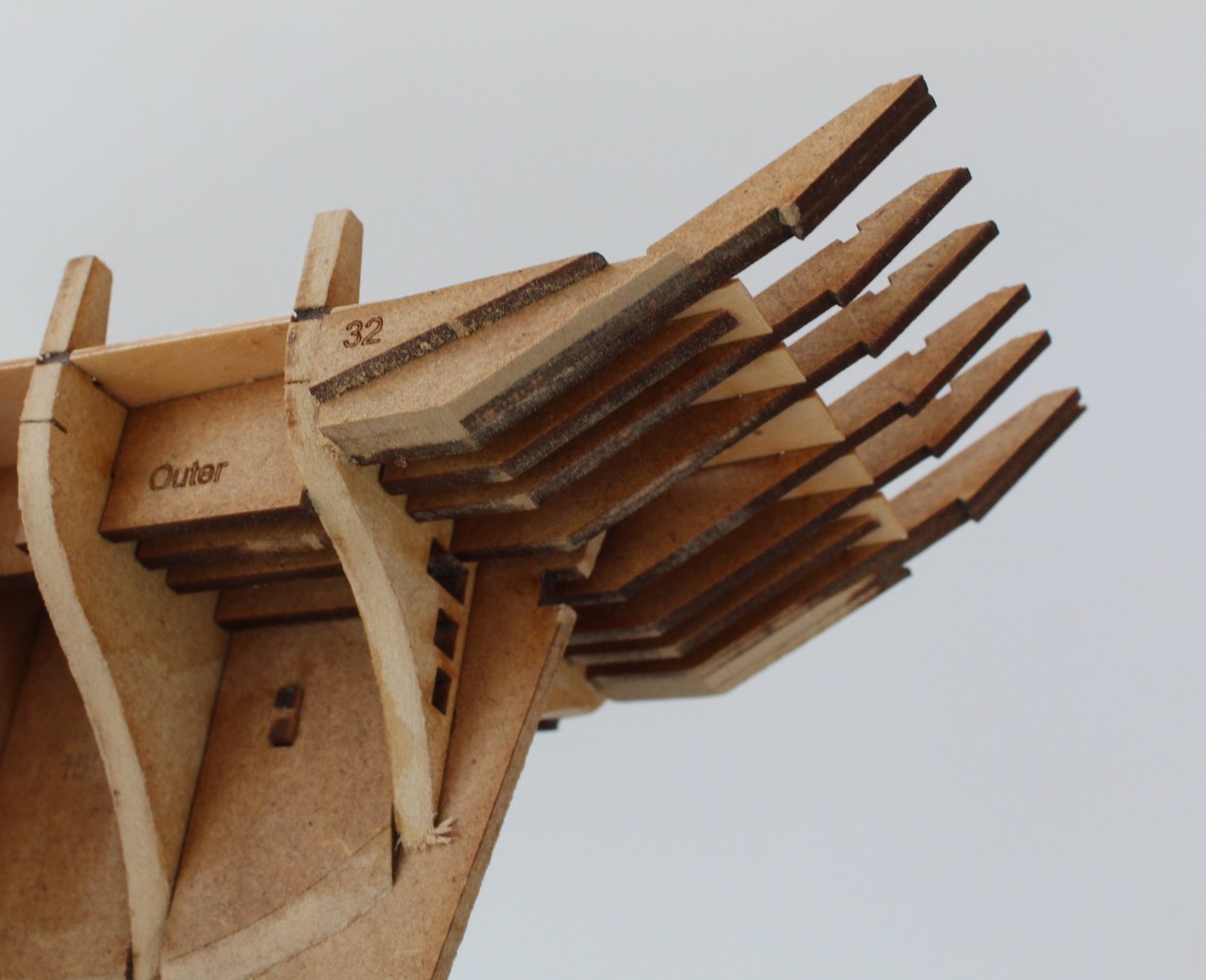
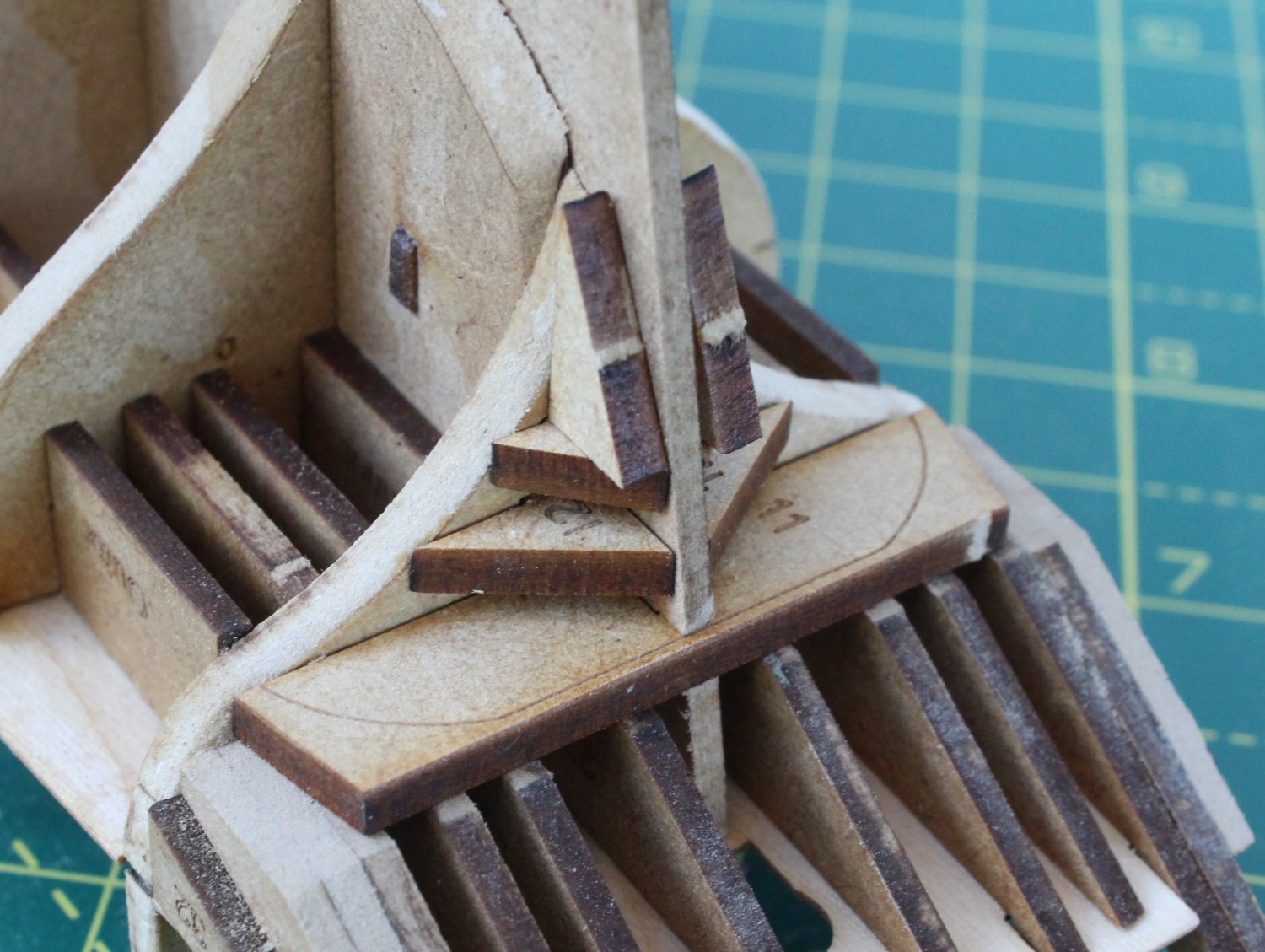
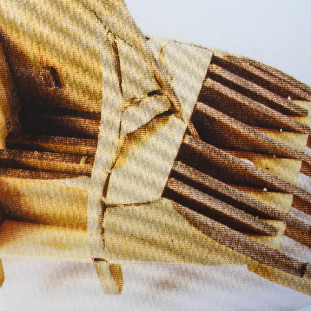
003 - Fitting Deck The assembled hull had been left for 18 hours to allow time for the glue to fully cure. The deck was then added to the hull. It is essential to ensure the deck edges are fully engaged with all the locating slots on the bulkheads. With the deck fully engaged I then brushed a diluted titebond solution to the joints. With the deck glued I then moved on to gluing the 3 off fillers to the outer stern frames. I then dry fitted the Stern Counter Frame and Stern Patterns (Lower. Middel and Upper). There is quite of bit of sanding required to get the required shape to the bow area, can be seen from the build manual photo. I have been debating if I should glue these filler parts in place or to do a pre-fair before fitting. When I built the Sphinx, I did mark and pre-fair the bow and stern filler patterns before fitting which I think this made the final fairing process much easier.


- 62 replies
-
- 1
-
-
- Saucy Jack
- vanguard models
- (and 3 more)
-
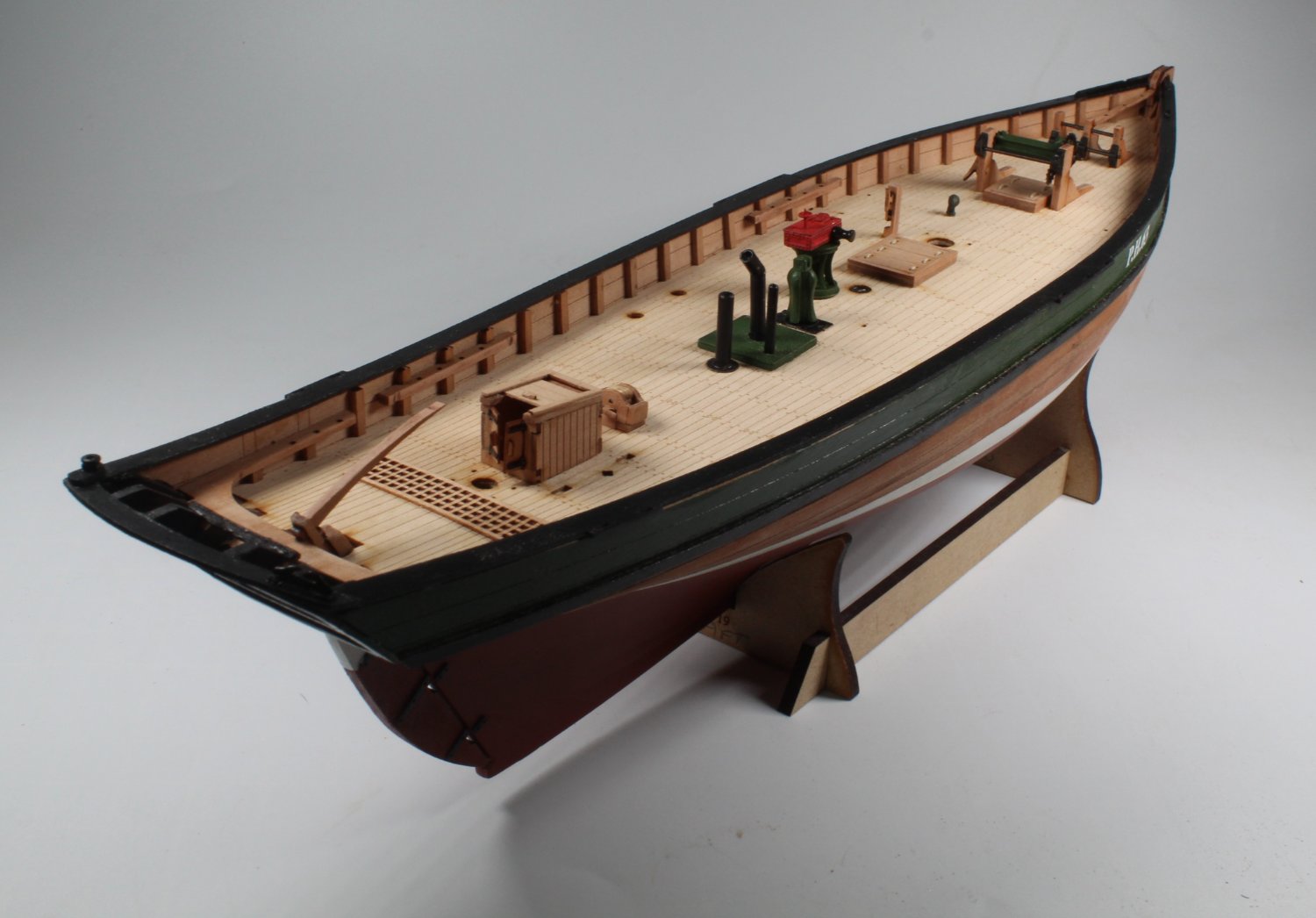
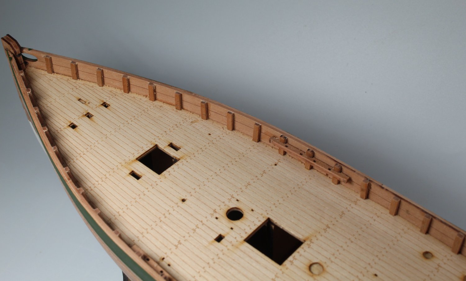
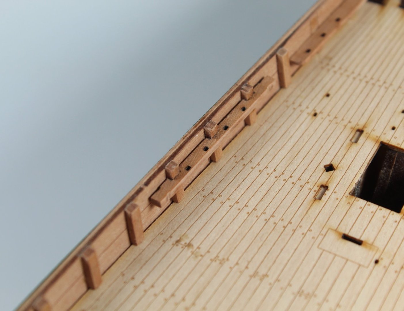
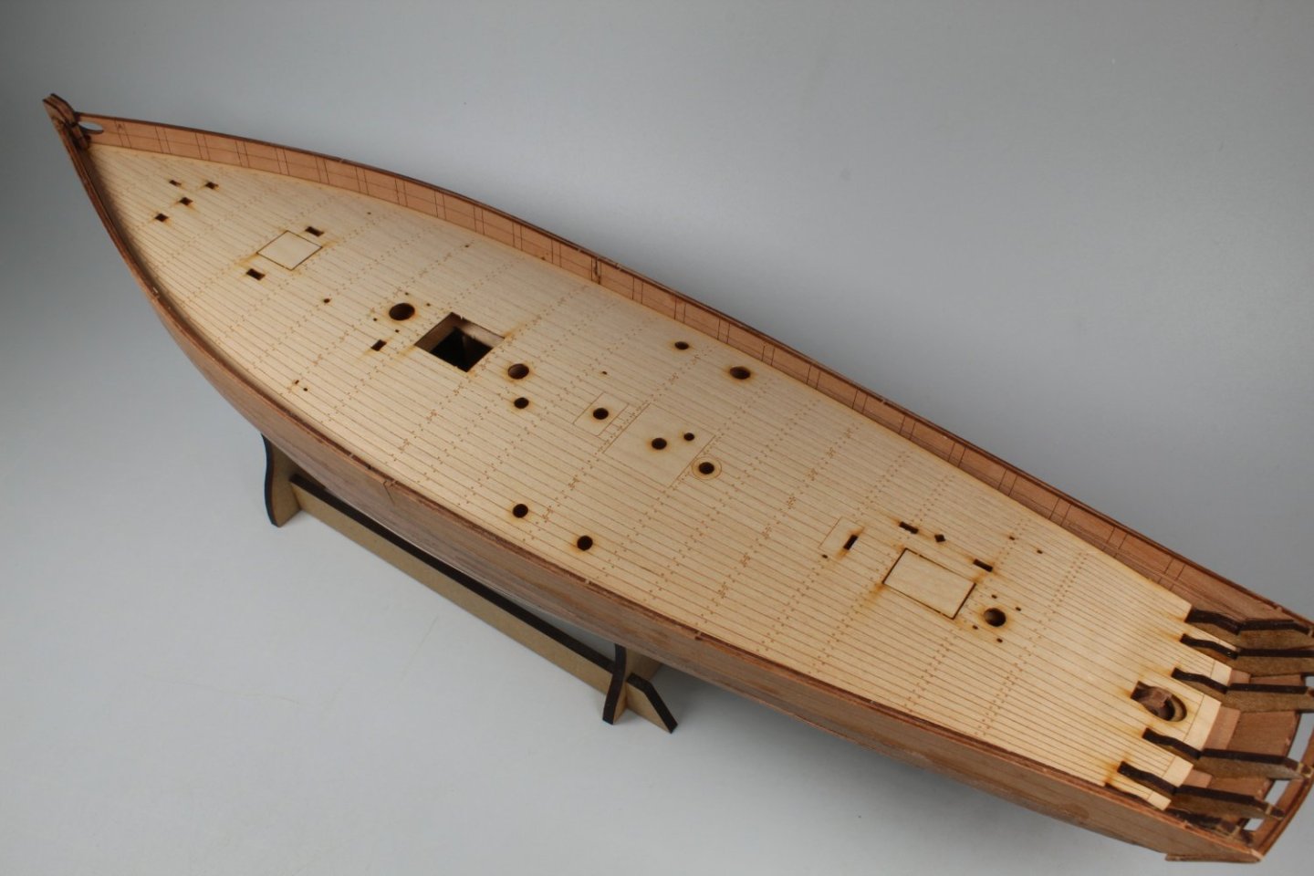
019 - Deck Fitting After removing the laser char from the edge of the maple veneer deck it was a perfect fit. Using a slightly diluted titebond mixture I applied a coating of glue to the false deck. The maple veneer deck was the added with a series of edge clamps to hold the veneer deck in place. Once the glue had cured, I test fitted the previously built deck furniture. The addition of the furniture does bring the boat to life. Next up will be adding all the timber heads to the inner bulwarks. When gluing the deck glue in place I also glued the outer decorative patterns to the rudder which, once cured, was then test fitted. It was a perfect fit.


- 106 replies
-
- 3
-
-
- Erycina
- Plymouth Trawler
- (and 3 more)
-
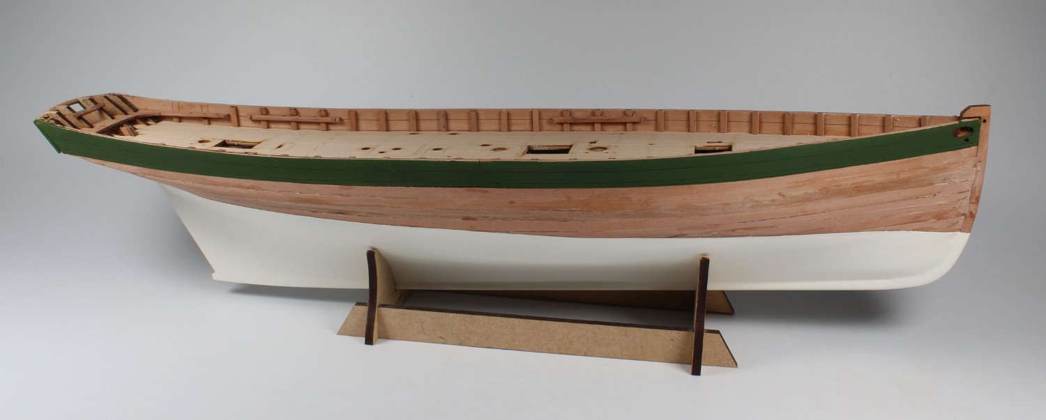
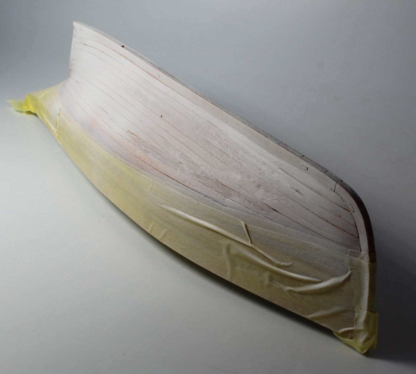
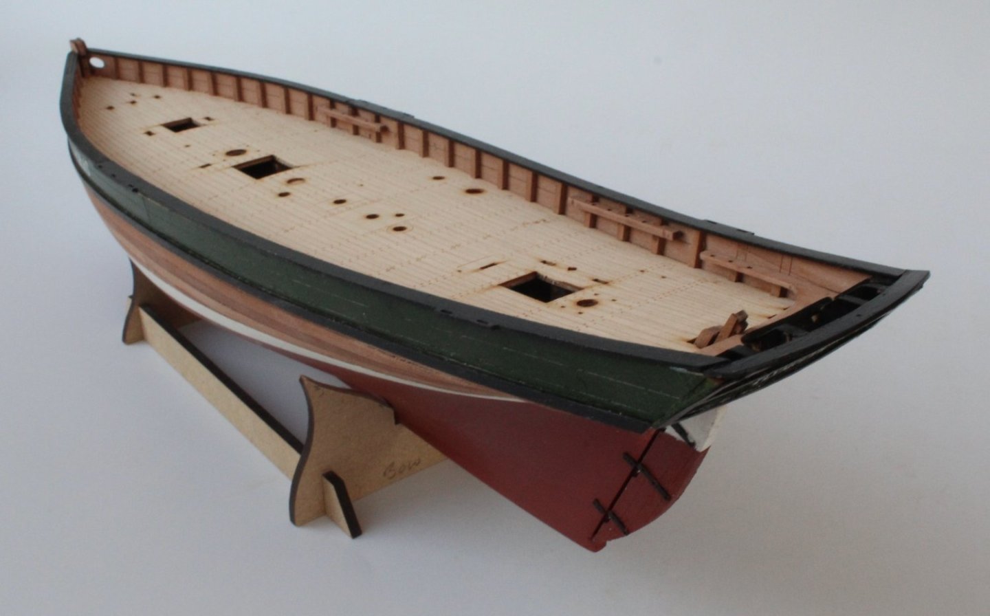
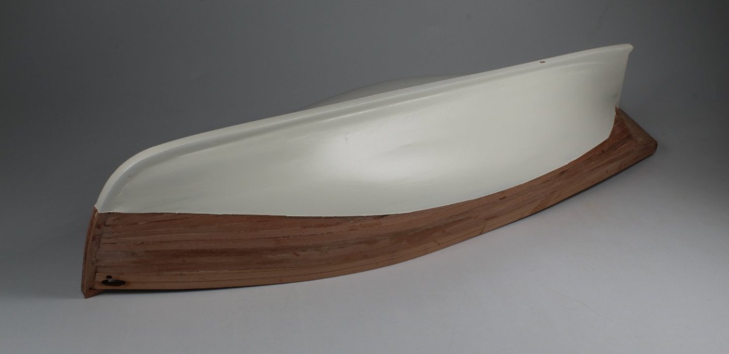
018 - Hull Smoothing Completed I took my time to sand, fill, paint the hull below the waterline. After a few iterations I am now reasonably happy with the end result. I will be spraying the hull with some red paint, but this will be done later on in the build process keeping in line with the build manual instructions. The next task was to remove the bulkhead ears, above the deck level, and to then sand flat. This was a simple straightforward task. The 0.8mm maple veneer deck was then test fitted. It was almost a perfect fit. I will just need to sand a little bit from the edges of the maple veneer deck. Fingers crossed that, like @James H prototype build, I will only have to remove the laser char at the edges for it to fit perfectly.

- 106 replies
-
- 6
-
-
- Erycina
- Plymouth Trawler
- (and 3 more)
-
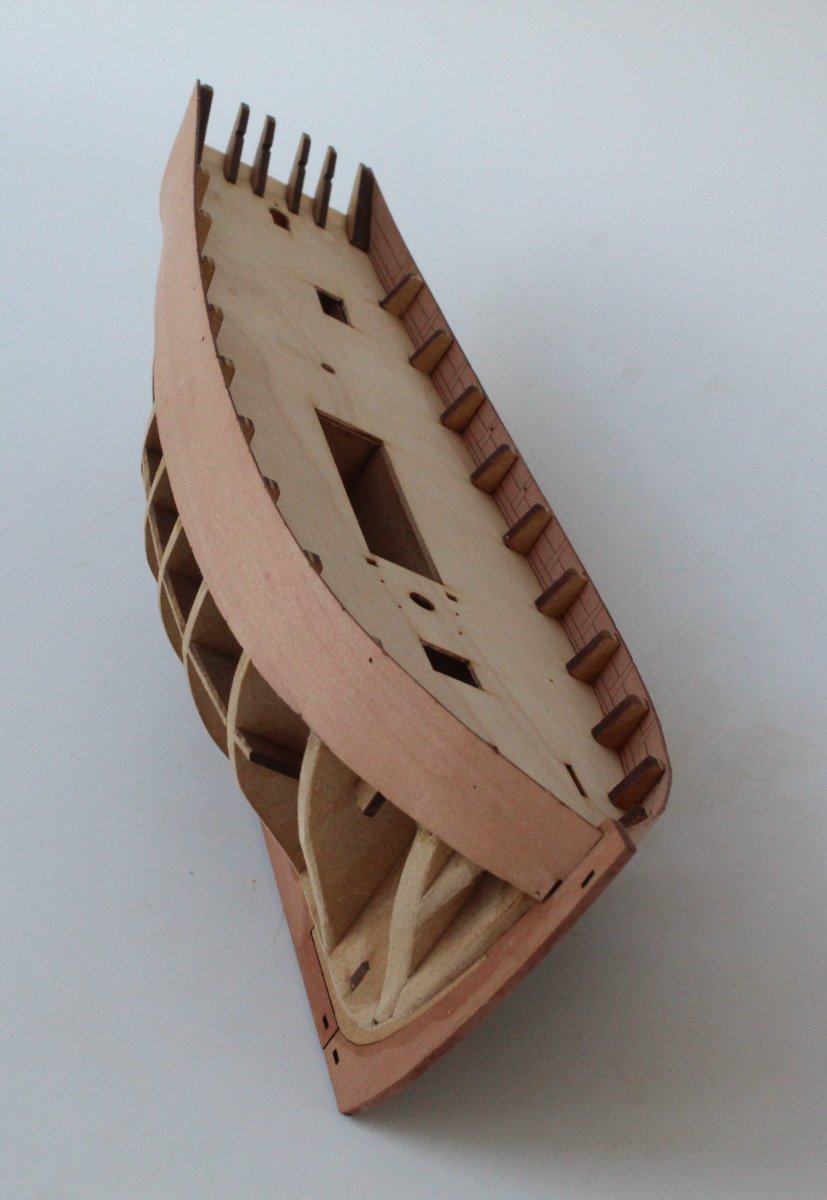
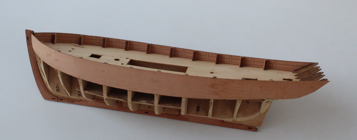
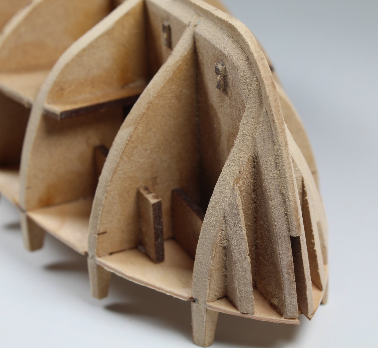
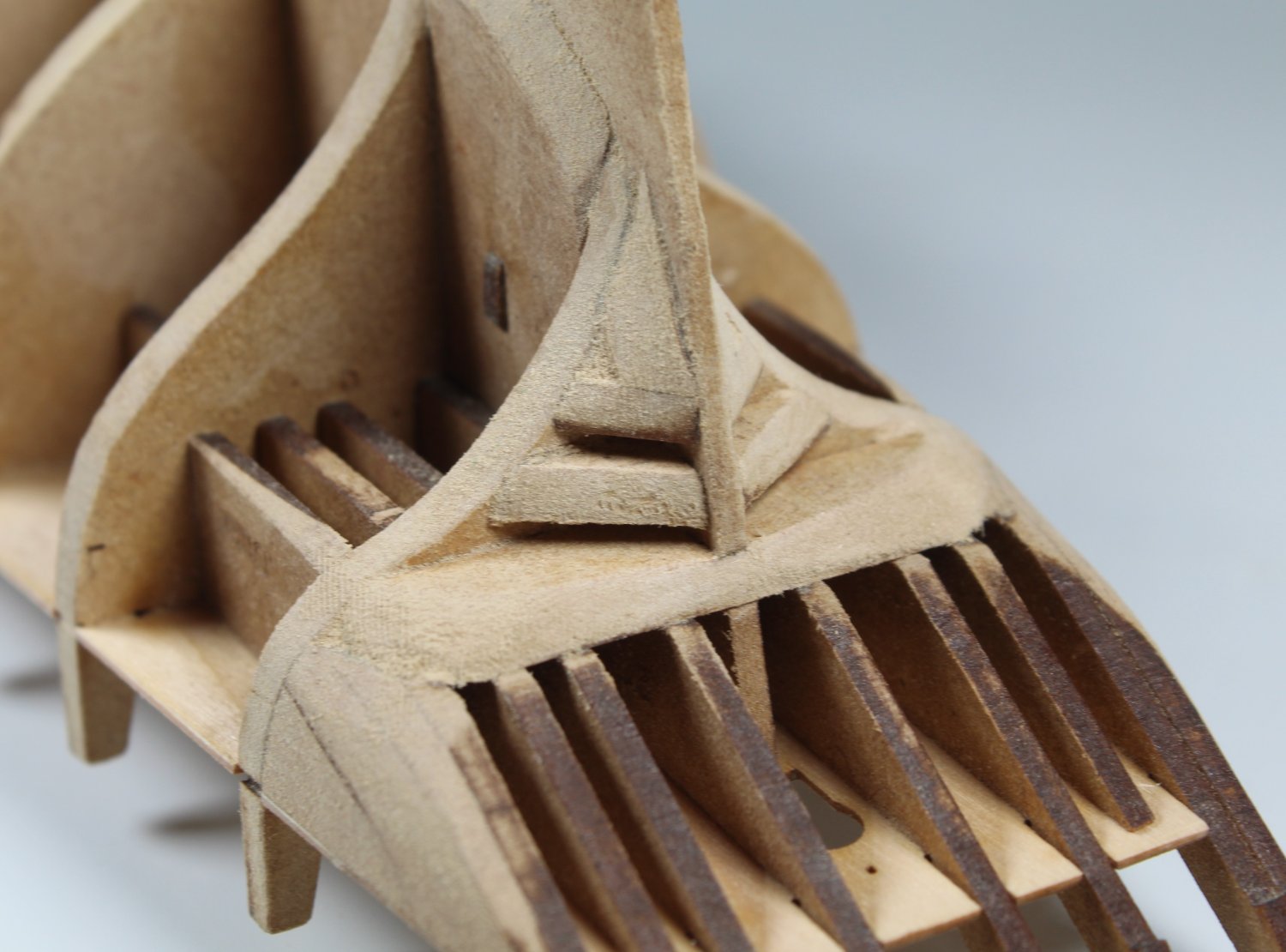
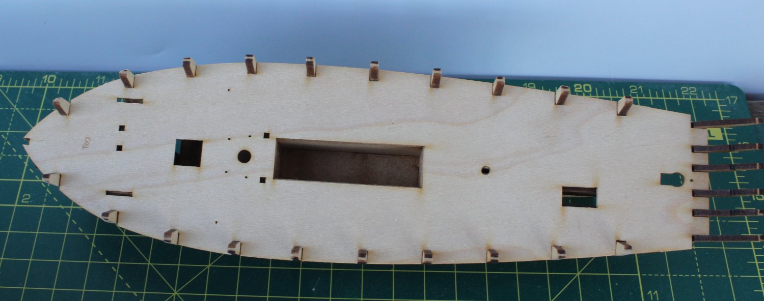
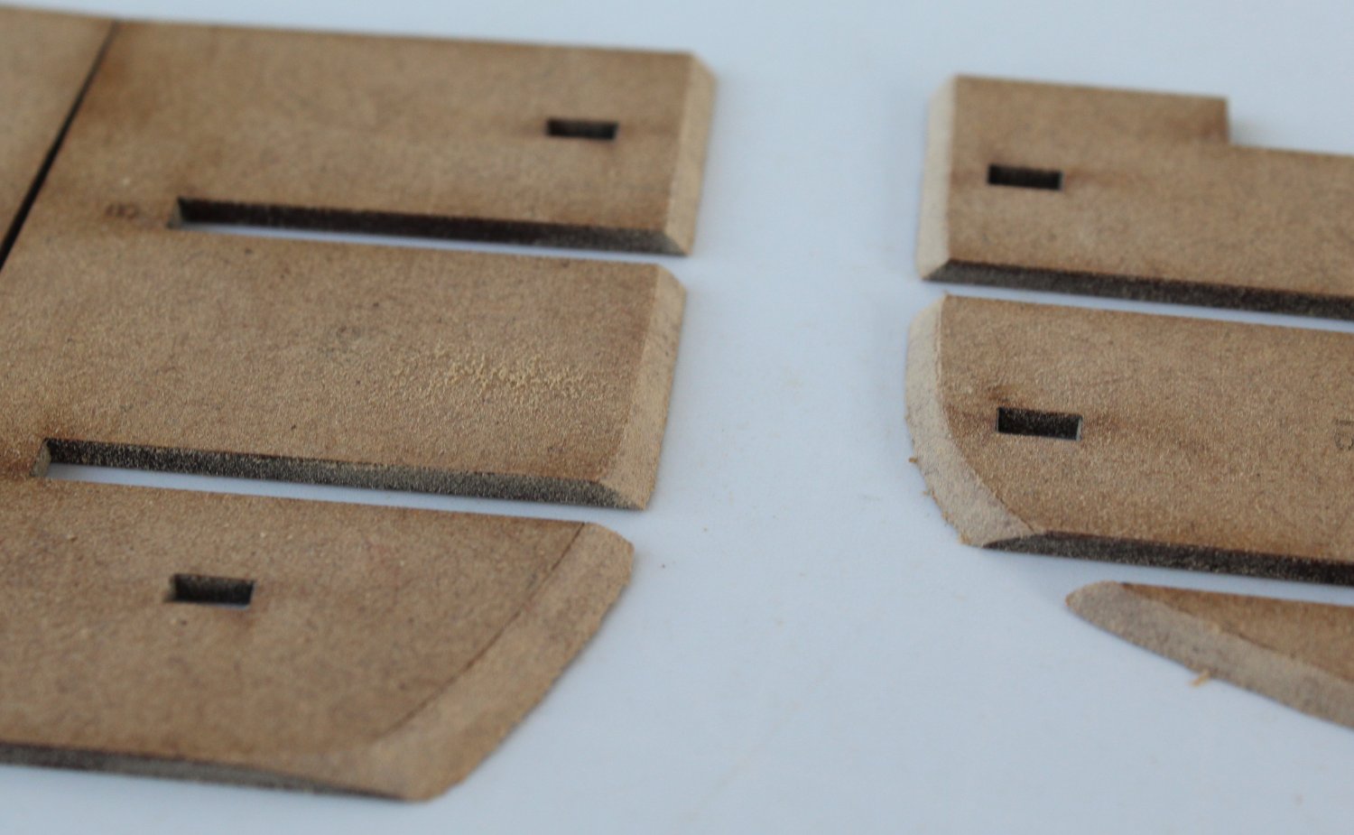
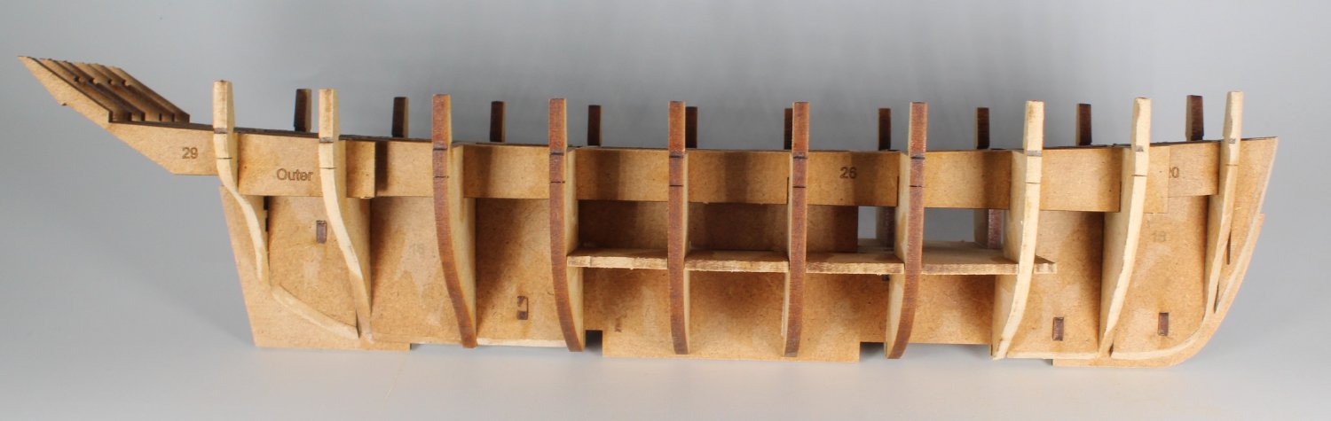
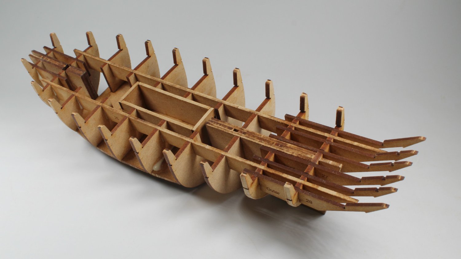
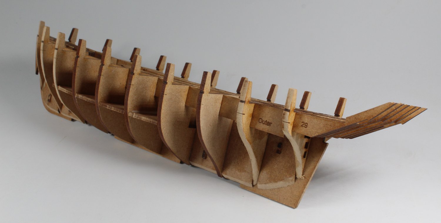
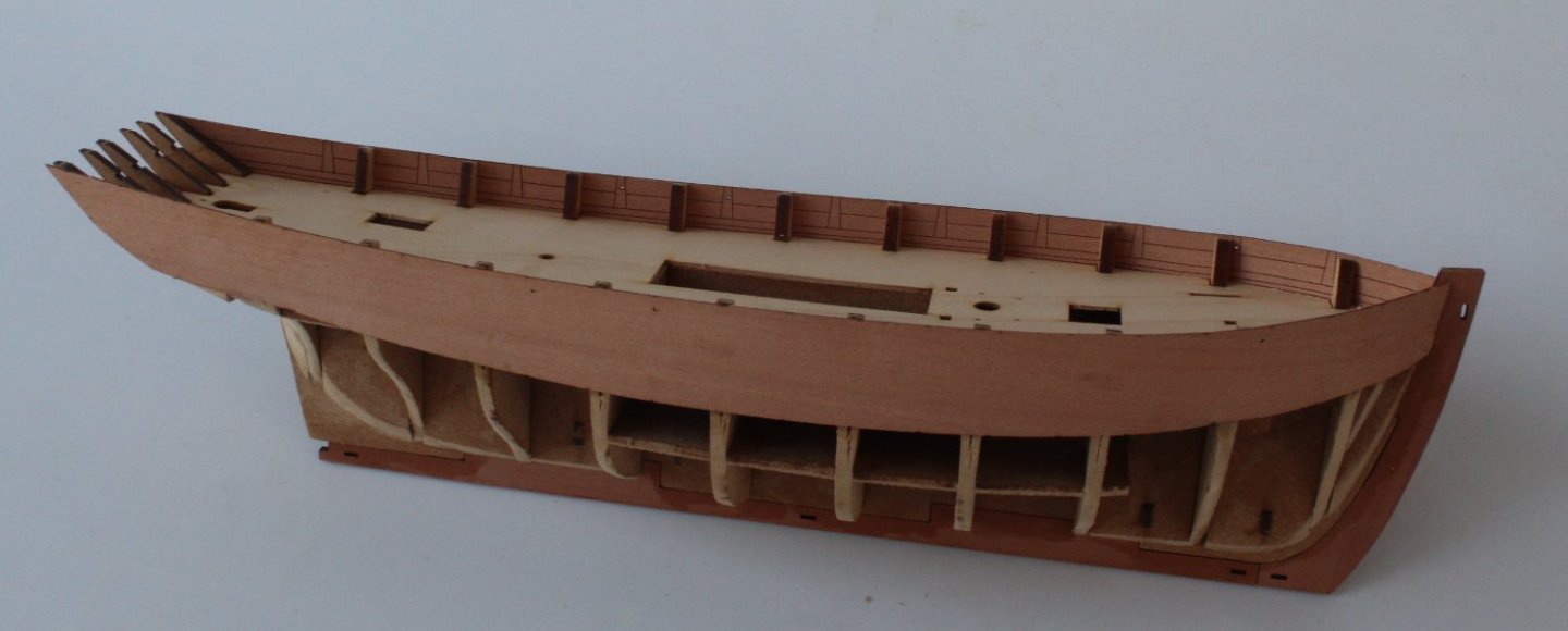
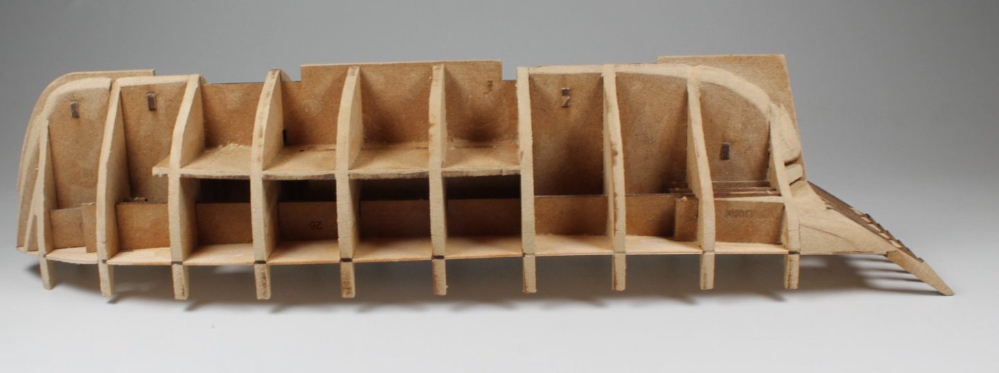
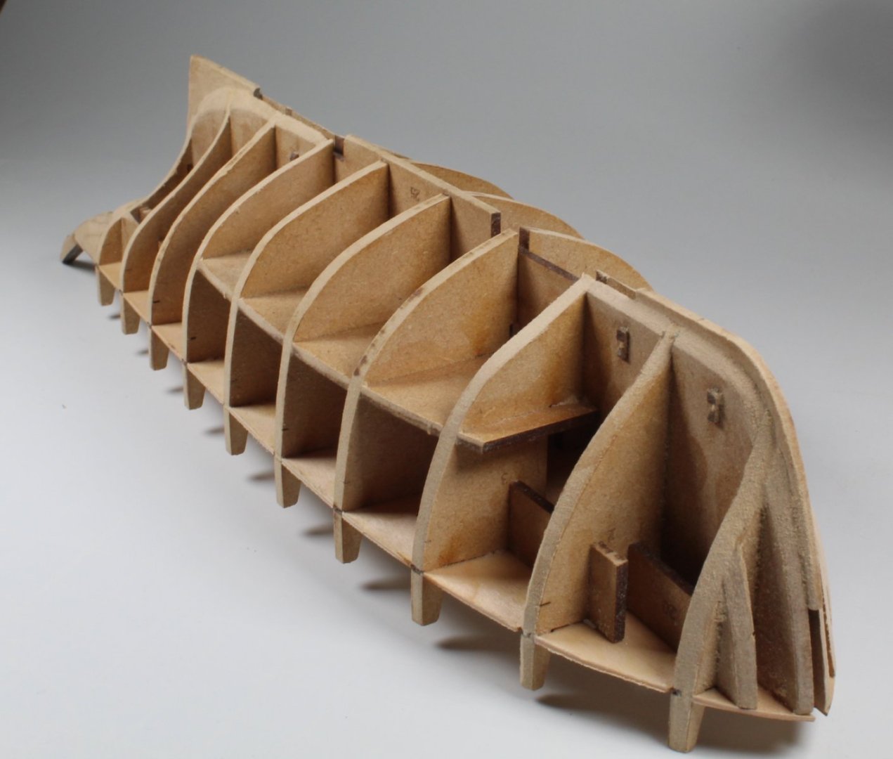
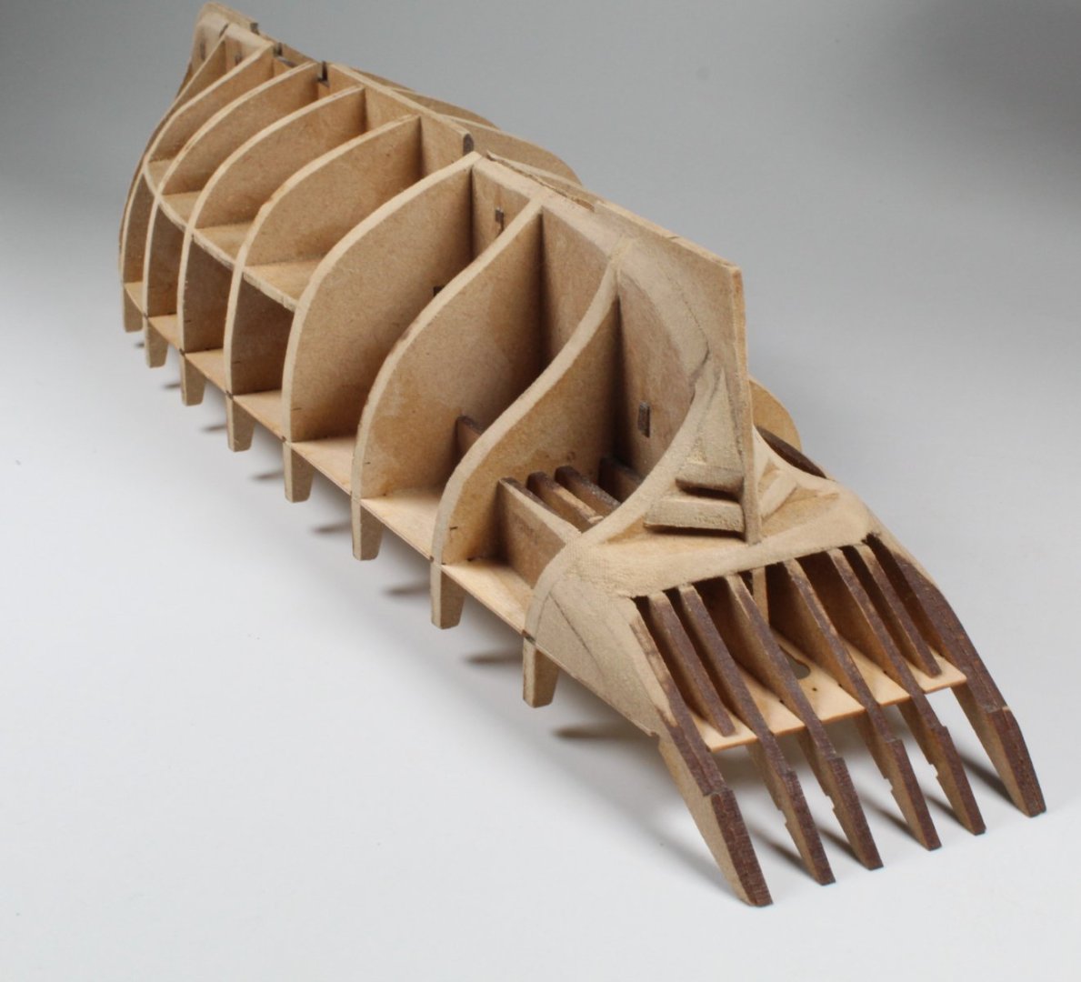
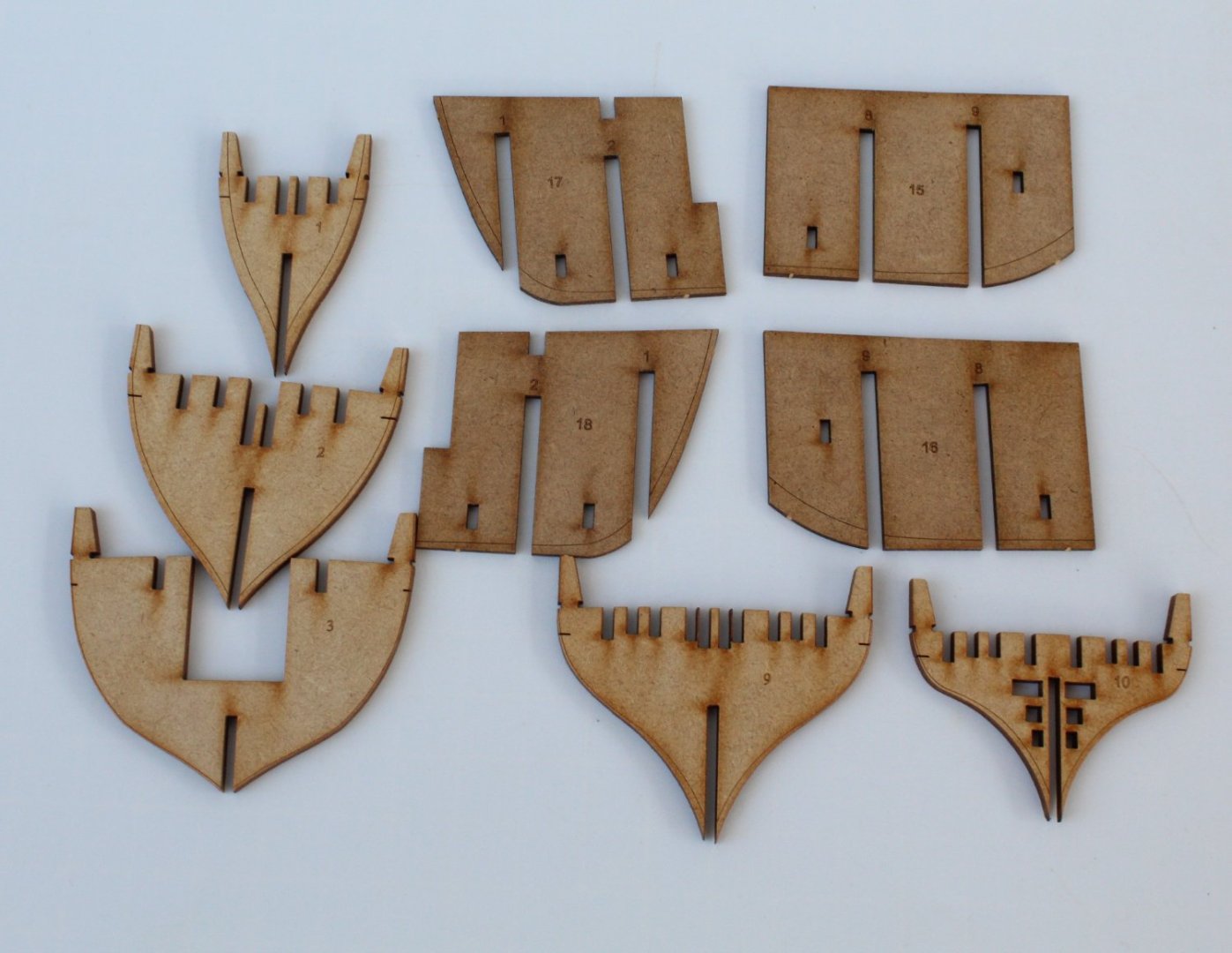
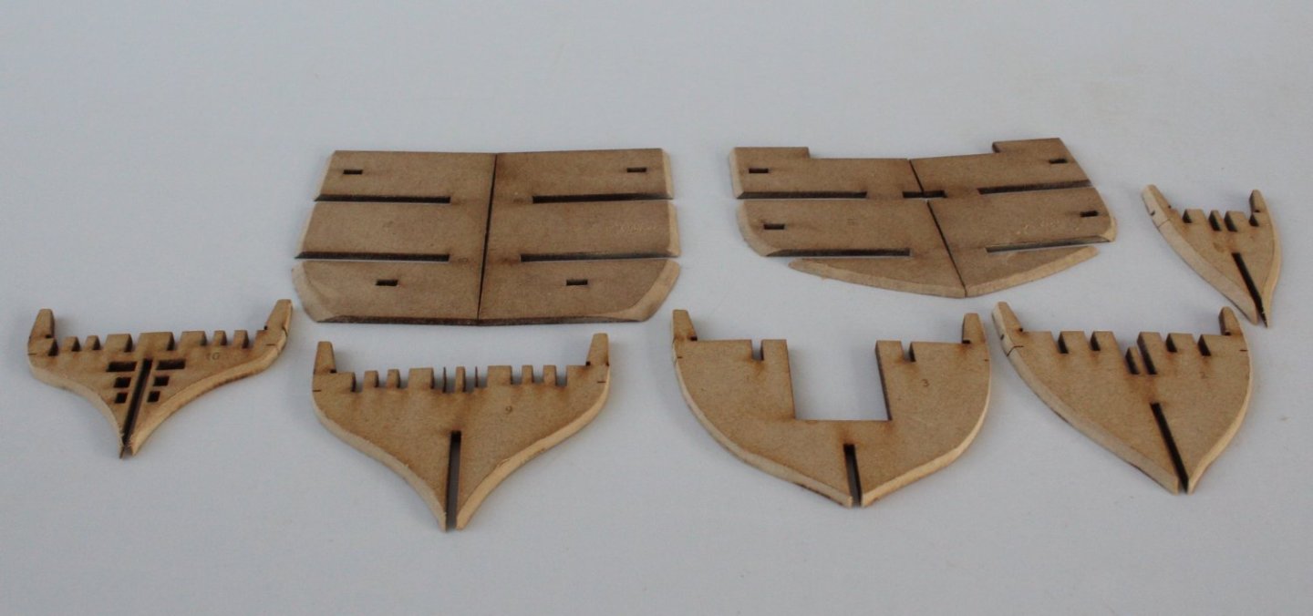
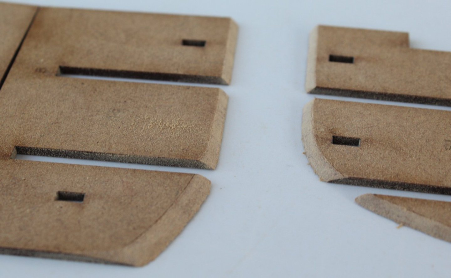
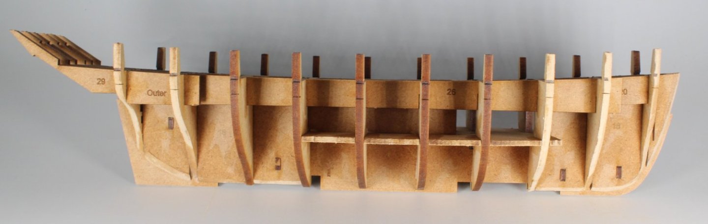
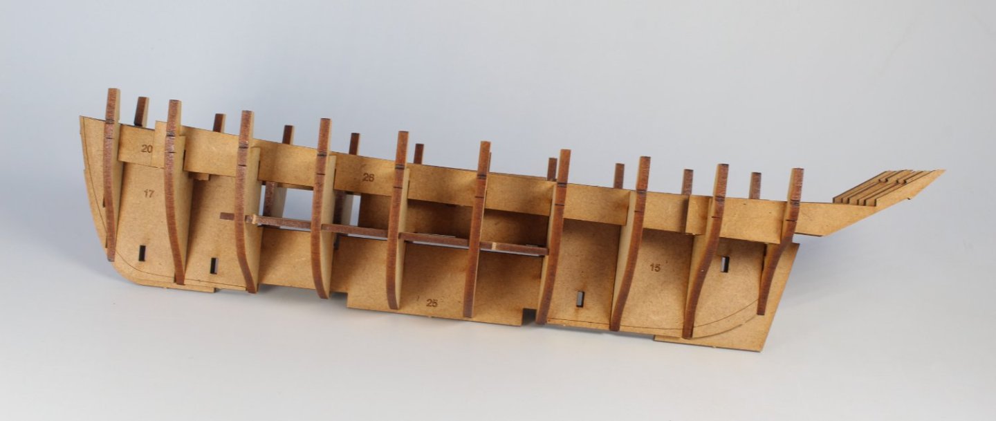
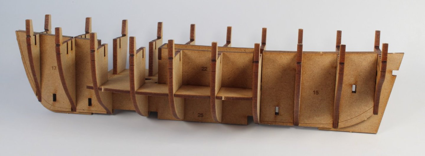
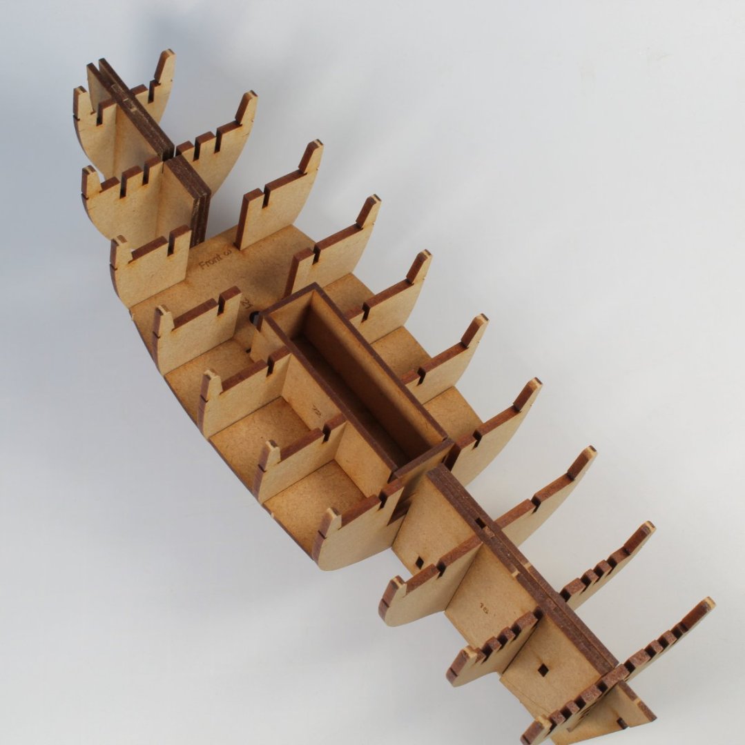
002 - Hull Build Stage 1 Completed All the stage 1 hull parts are ready for a dry fit assembly. All the above parts slotted together very well. The hull was then disassembled, and the bulkheads and planking edge patterns were put to one side ready for the pre fair to the marked lines. Using a rotary sanding took the bulkheads and planking edge patters were beveled to the marked line. The hull was then reassembled in stages. The bow and aft planking edge parts were glued in place. After the deck was added the Fish Well parts were glued in place. Once all the bulkheads, the longitudinal hull brace and stern frame patterns had been properly fitted diluted titebond glue was brushed into all the joints. The hull will now be left to full cure overnight. You will note in the following photo that I did remove the laser char for the fish well top edges.


- 62 replies
-
- 1
-
-
- Saucy Jack
- vanguard models
- (and 3 more)
-
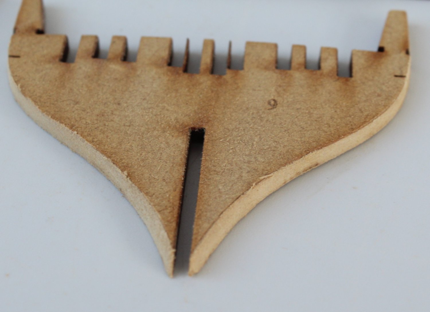
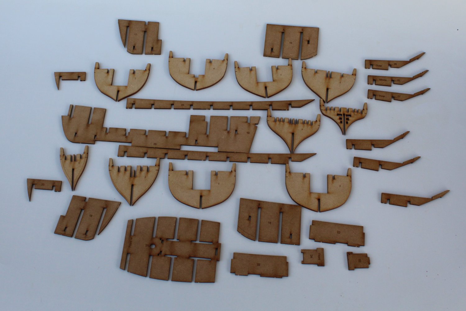
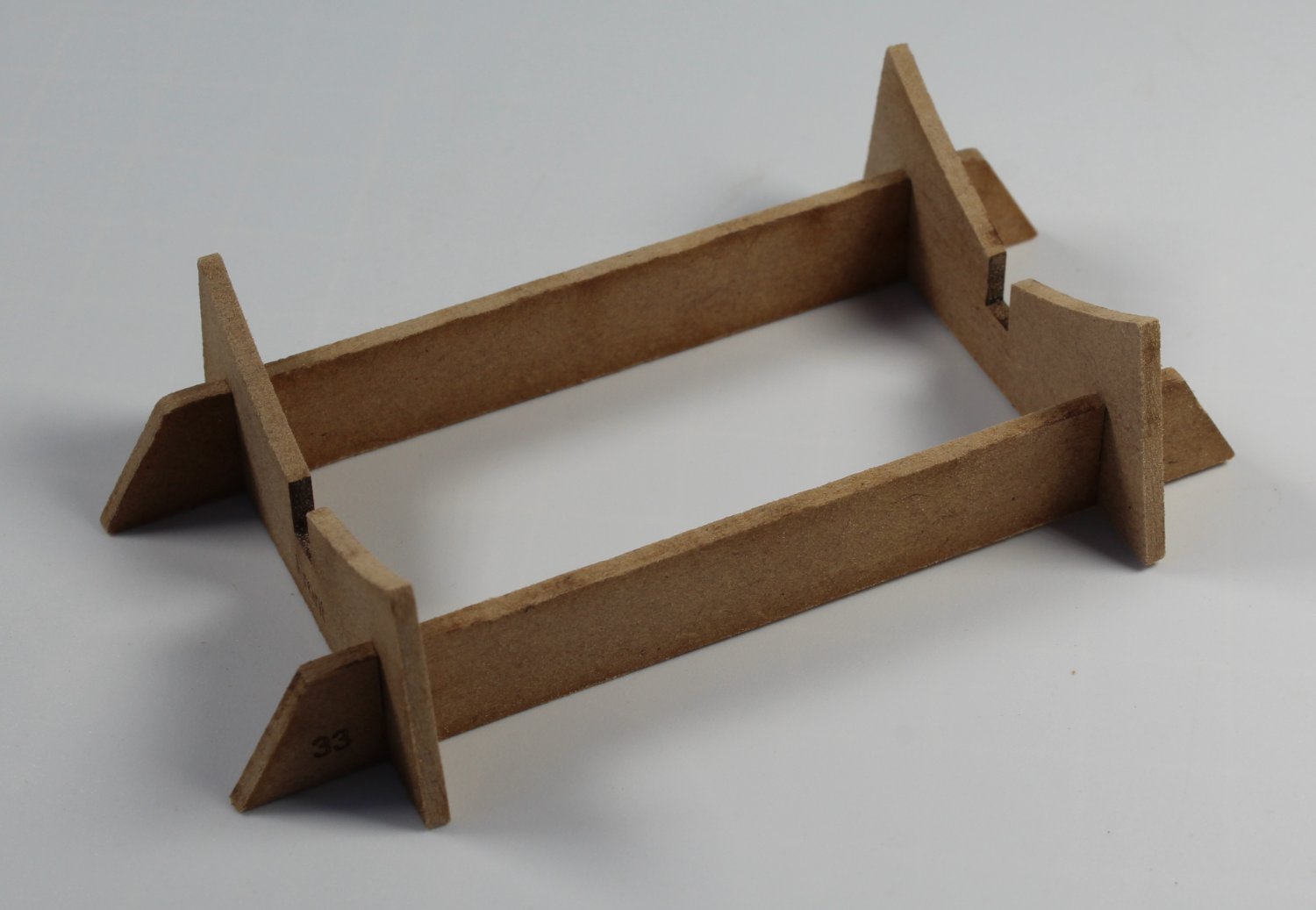
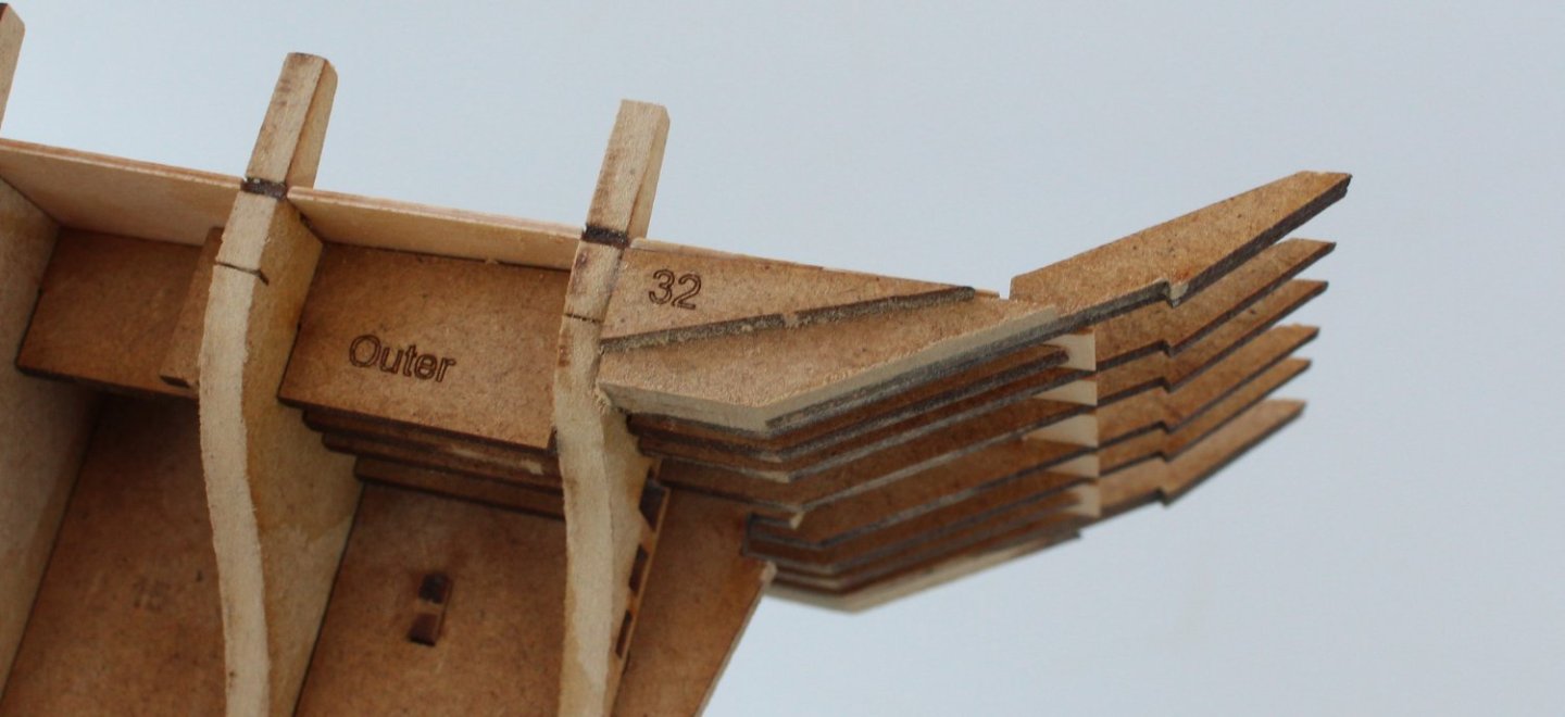
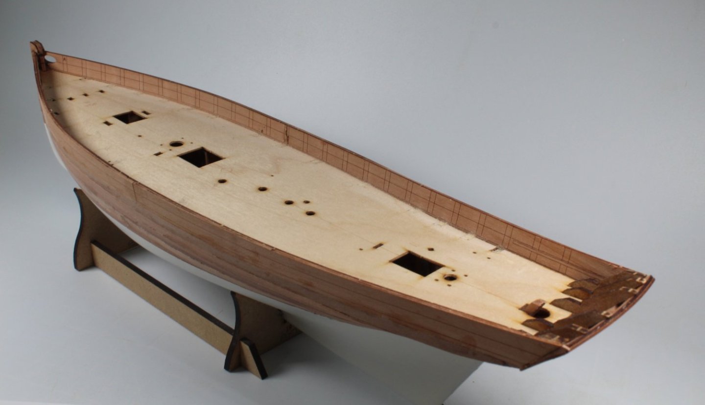
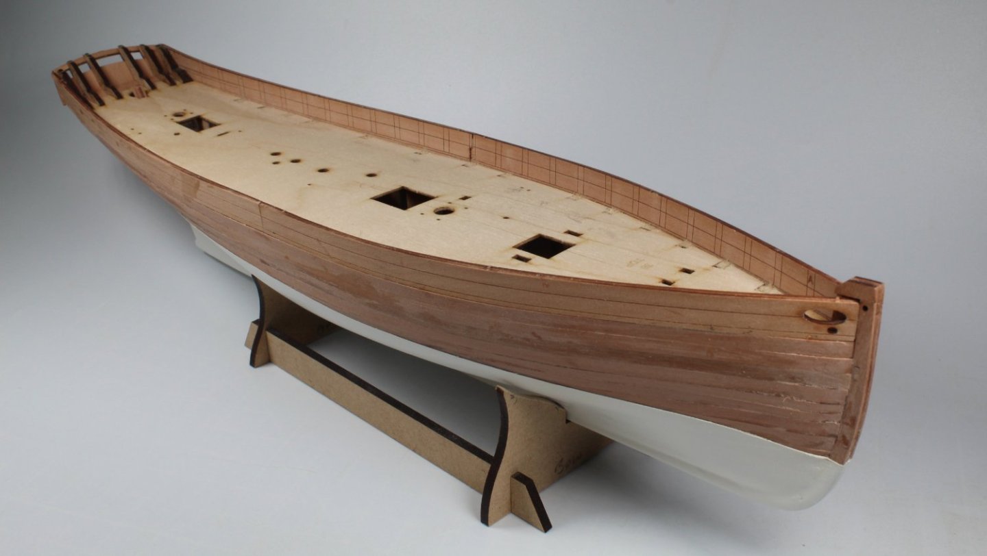
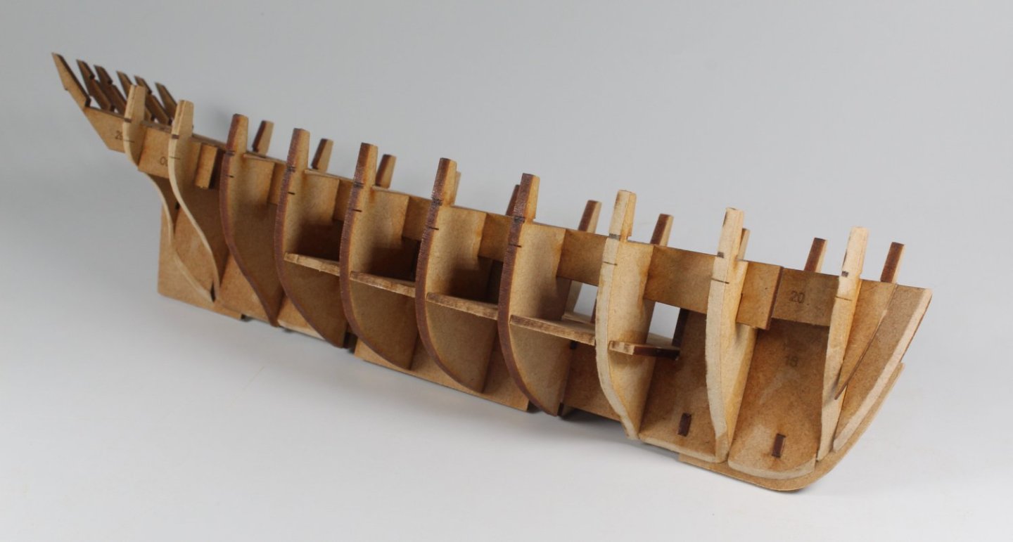
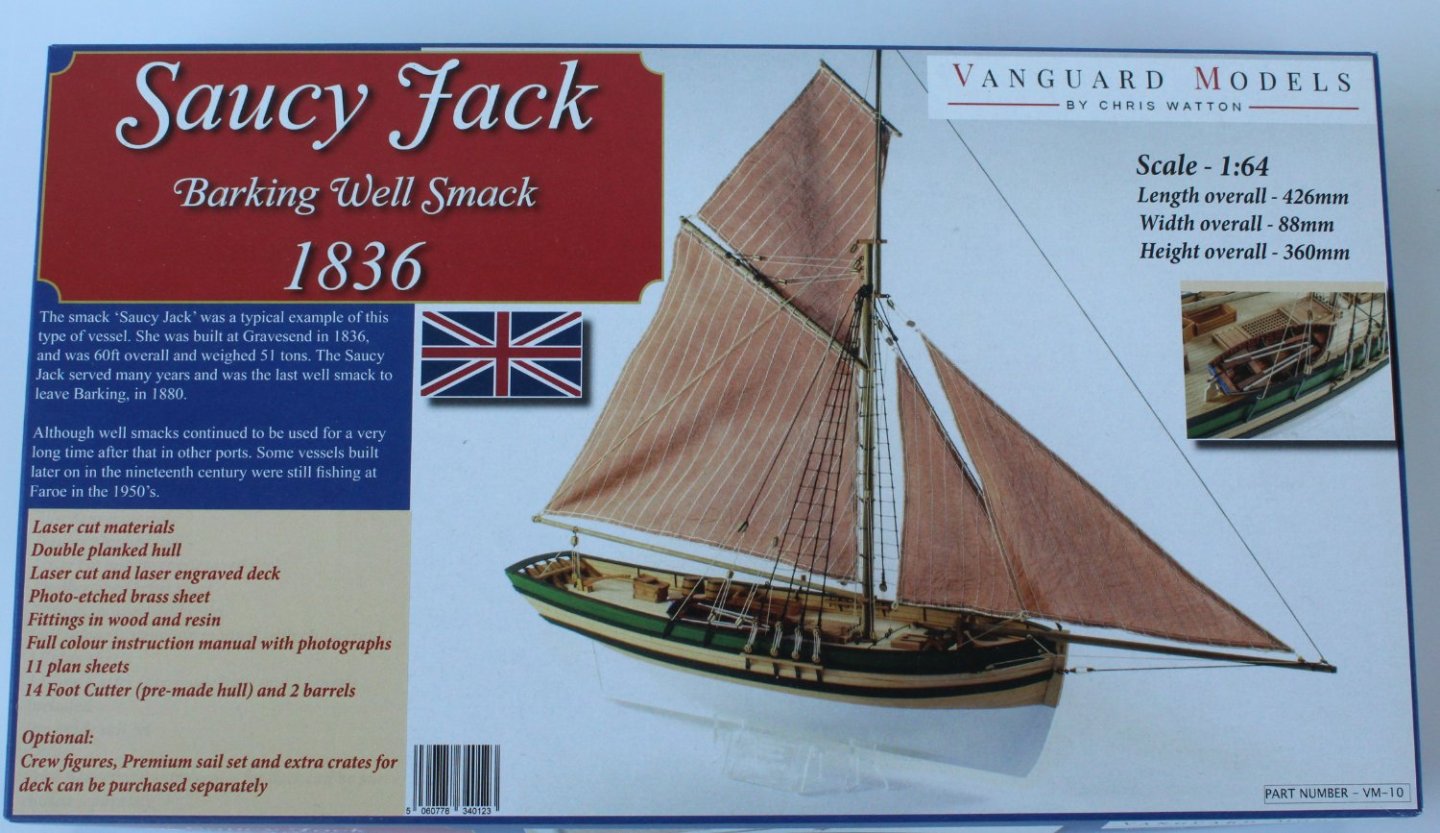
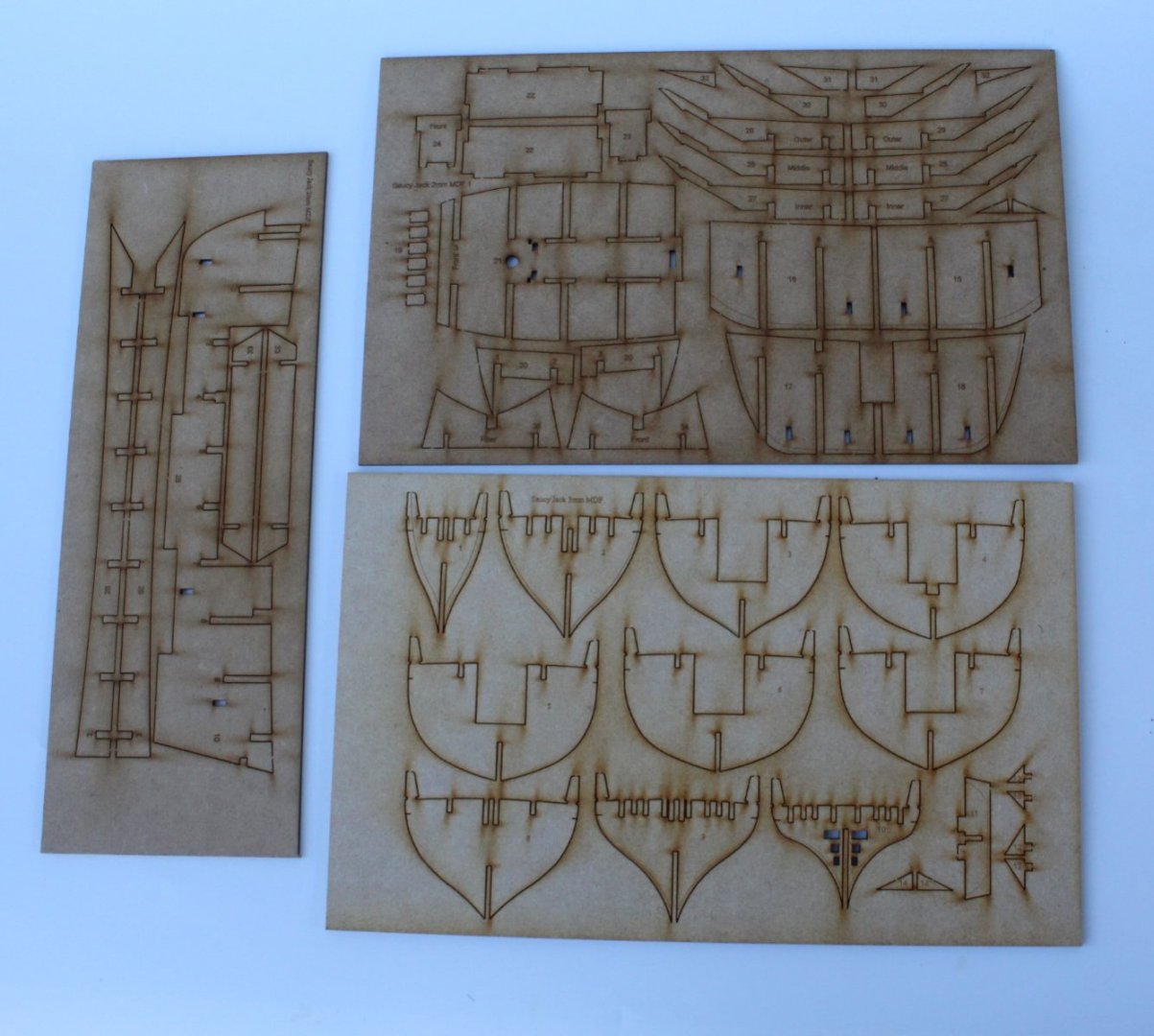
001 - Starting Point As I have some free time between painting and sanding my Erycina hull I thought I would have a look at the Saucy Jack. This looks to be a nice small and relatively simply project to build. As with all my previous Vanguard Model projects I get a warm feeling when inspecting the kit box and its contents. Once again everything appears to be of a very high quality (materials, build manual, plan sheets, etc.). I do not expect to make much progress with this build in the short term as I will be mainly working on the Erycina. The temporary stand was a very simple item to construct. I did opt to remove the laser char from the visible edges even though there is no need to do so. I then released a few parts from the MDF sheets and did a dry fit assembly. Everything slotted together very well, without any issues. This dry fit will have to be disassembled so I can fair the bulkheads and the planking edge patterns to the guidelines provided. Once the hull is fully assembled and before I start the planking phase the hull will require a final fairing process.

- 62 replies
-
- 3
-
-
- Saucy Jack
- vanguard models
- (and 3 more)
-
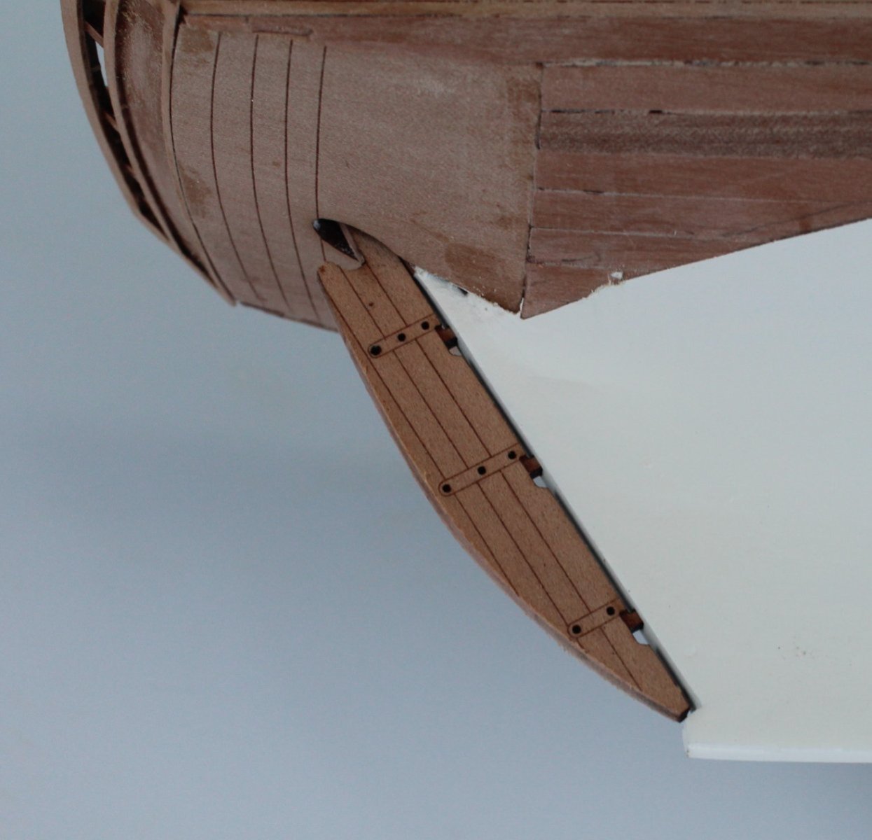
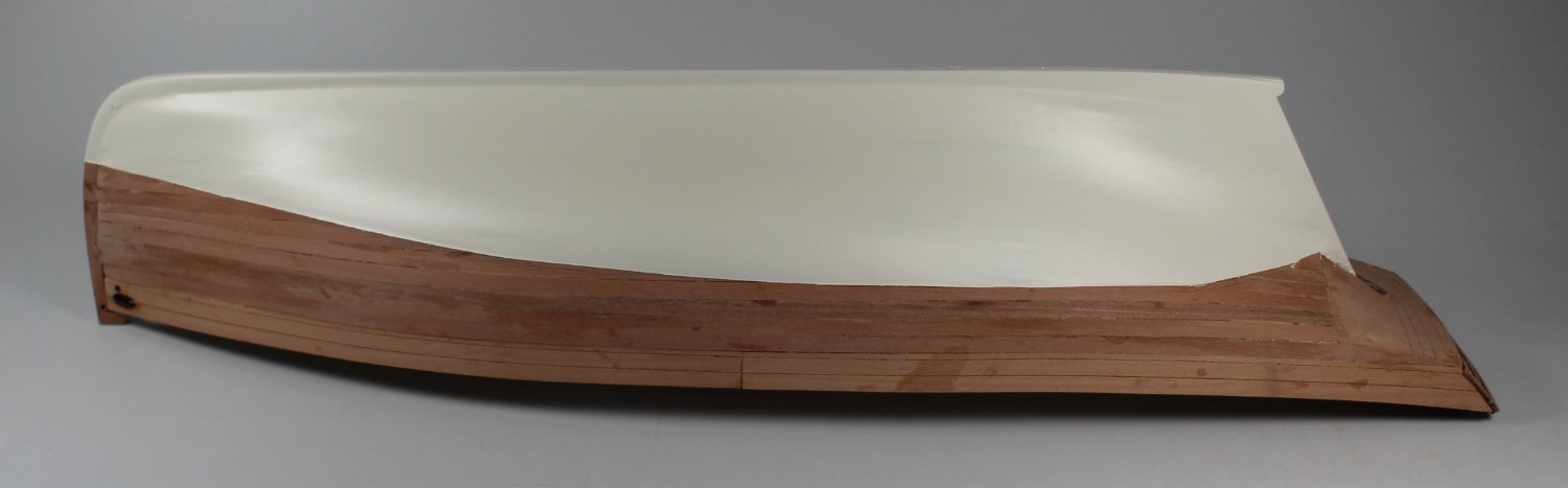
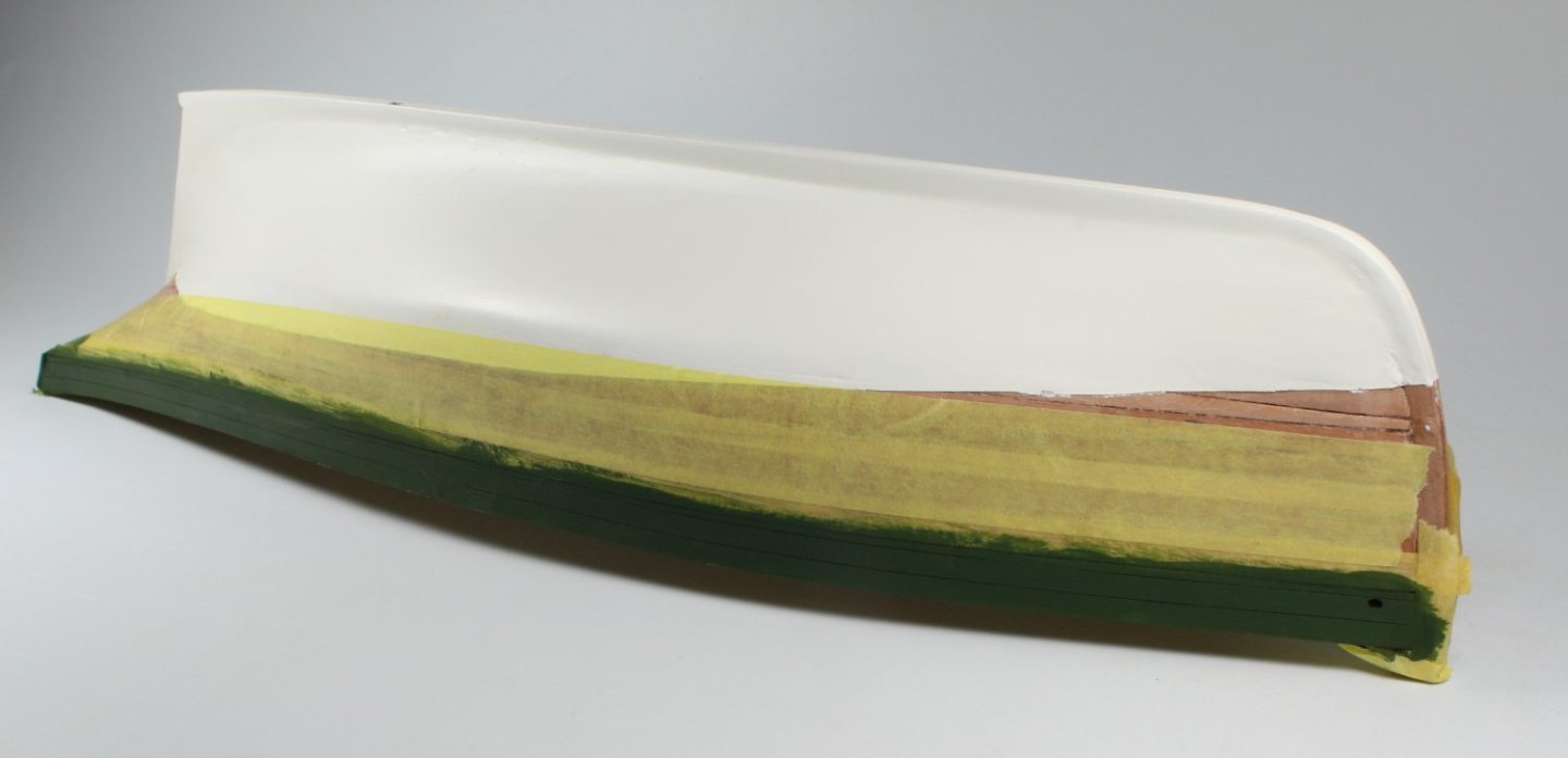
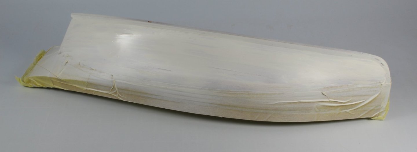
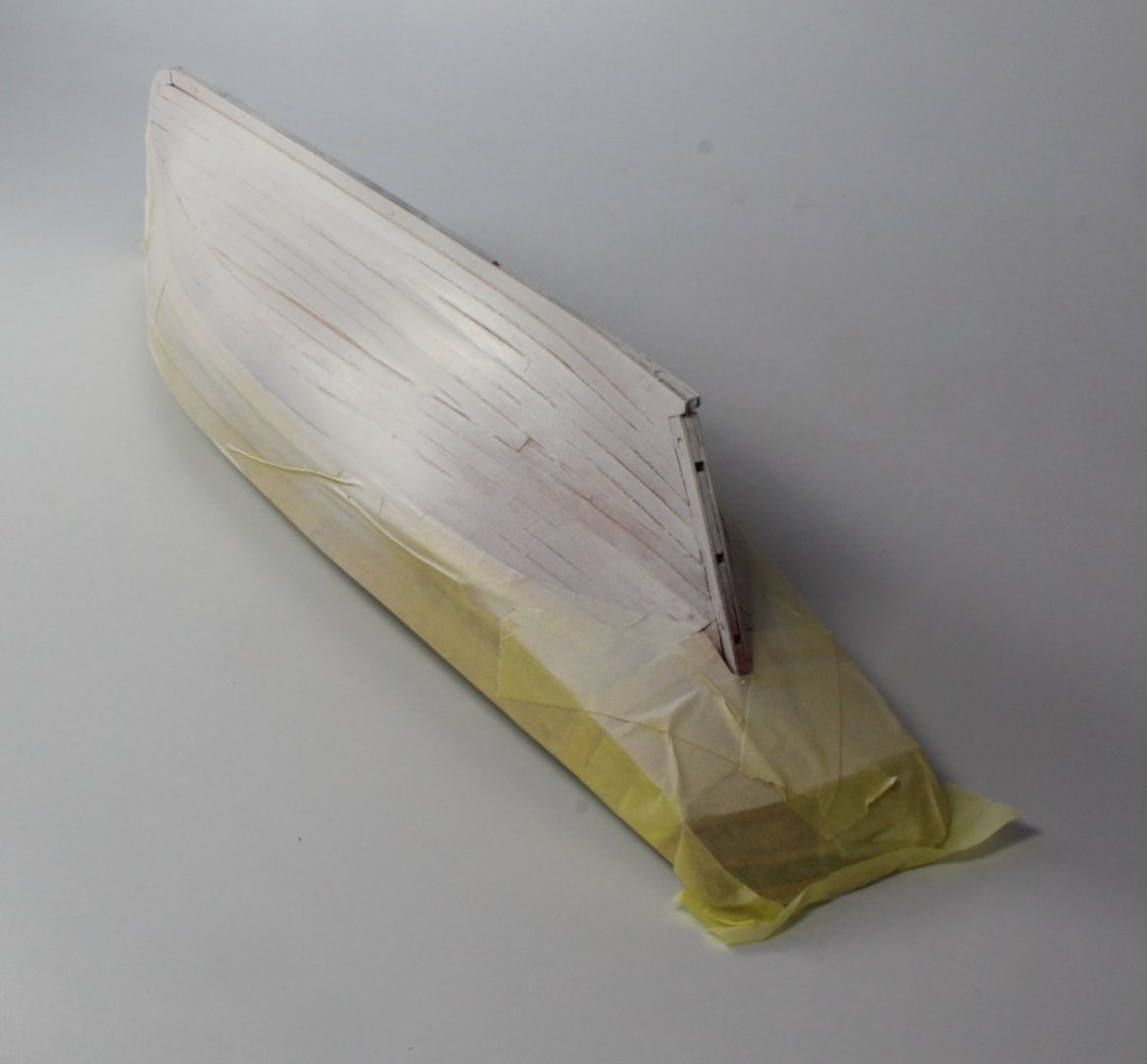
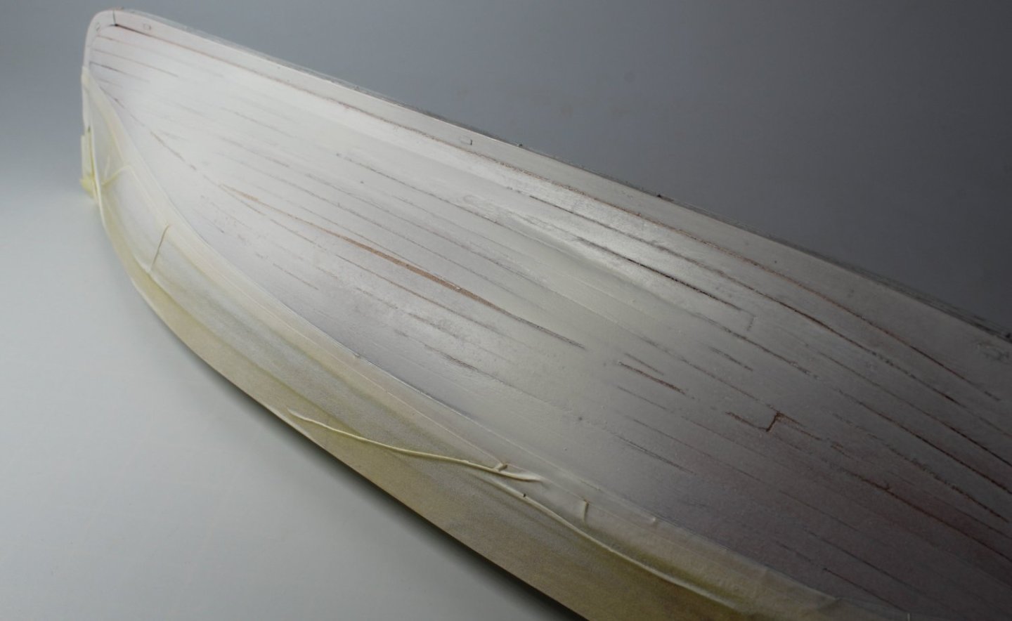
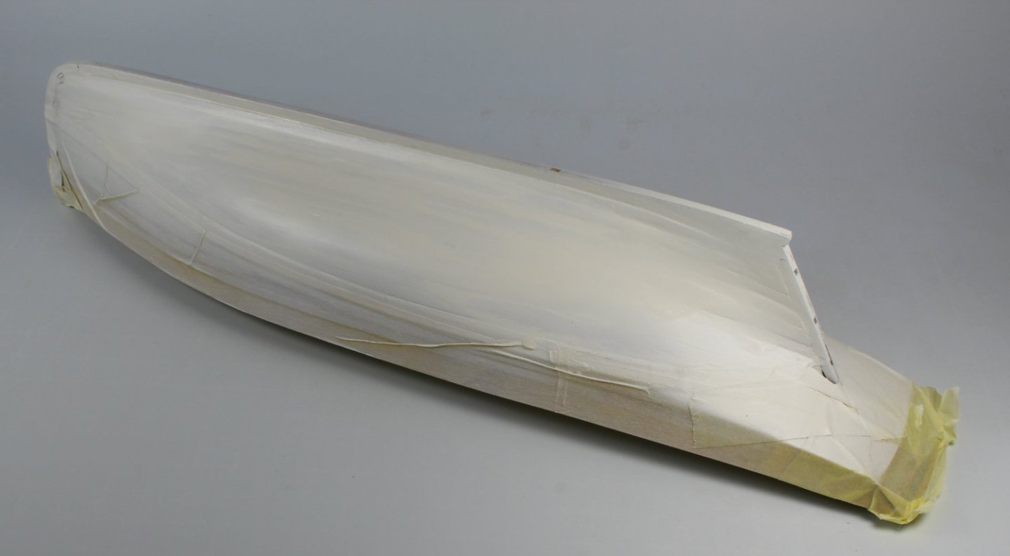
017 - Smoothing and Filling The Hull After the initial sanding process, using 120 and the 320 grit sandpaper the hull looked and felt smooth. I then applied a thin coat of white paint. As can be seen in the following three photo's the paint really helps to highlight all the problems. Once the paint had fully dried, I applied a filler solution to all the gaps and dips. The filler solution used was diluted Roneal natural wood filler mixed with an equal measure of titebond original. Once the mixture had hardened the hull was sanding smooth removing all the excess paint and filler. Another coat of white paint was then applied. As can be seen in the final two photos below the painted section of the hull looks much better. It is still not perfect. Once the paint has had time to dry more filler will be applied as necessary and the hull will be sanded smooth again and then repainted. This is a slow painstaking process, and it can take a few sanding and painting steps to complete the job. It is well worth the time and effort required to get a nice smooth hull.

- 106 replies
-
- 3
-
-
- Erycina
- Plymouth Trawler
- (and 3 more)
-
Many thanks. I'm no smarter, I just try to learn from all my previous builds and from studying other people's build logs.
-
I have two waterline marker tools, an Amati one and one I bought from Vanguard Models. I prefer the Vanguard Models tool. It can be tricky to use and mark under the stern counter. However once the tape has been added I find it easy to check the alignment with the waterline marker tool.
-
A good start
-
Many thanks. I had noted the plans were not 1:1 scale (as you noted) and I took that into account.
- 106 replies
-
- 1
-
-
- Erycina
- Plymouth Trawler
- (and 3 more)