HOLIDAY DONATION DRIVE - SUPPORT MSW - DO YOUR PART TO KEEP THIS GREAT FORUM GOING! (Only 72 donations so far out of 49,000 members - Can we at least get 100? C'mon guys!)
×


Glenn-UK
-
Posts
3,158 -
Joined
-
Last visited
Content Type
Profiles
Forums
Gallery
Events
Everything posted by Glenn-UK
-
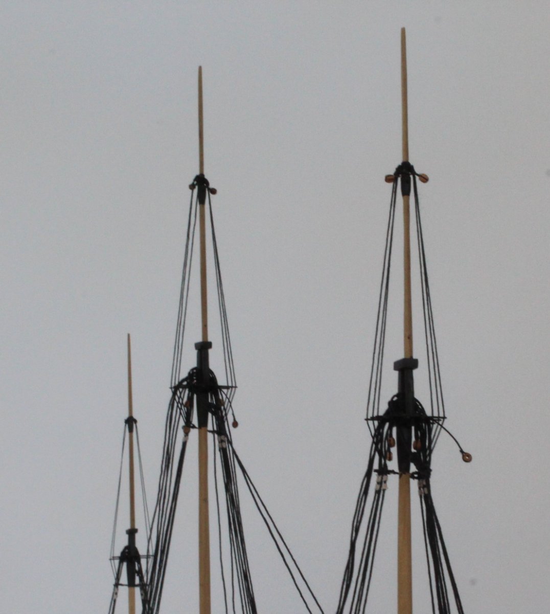
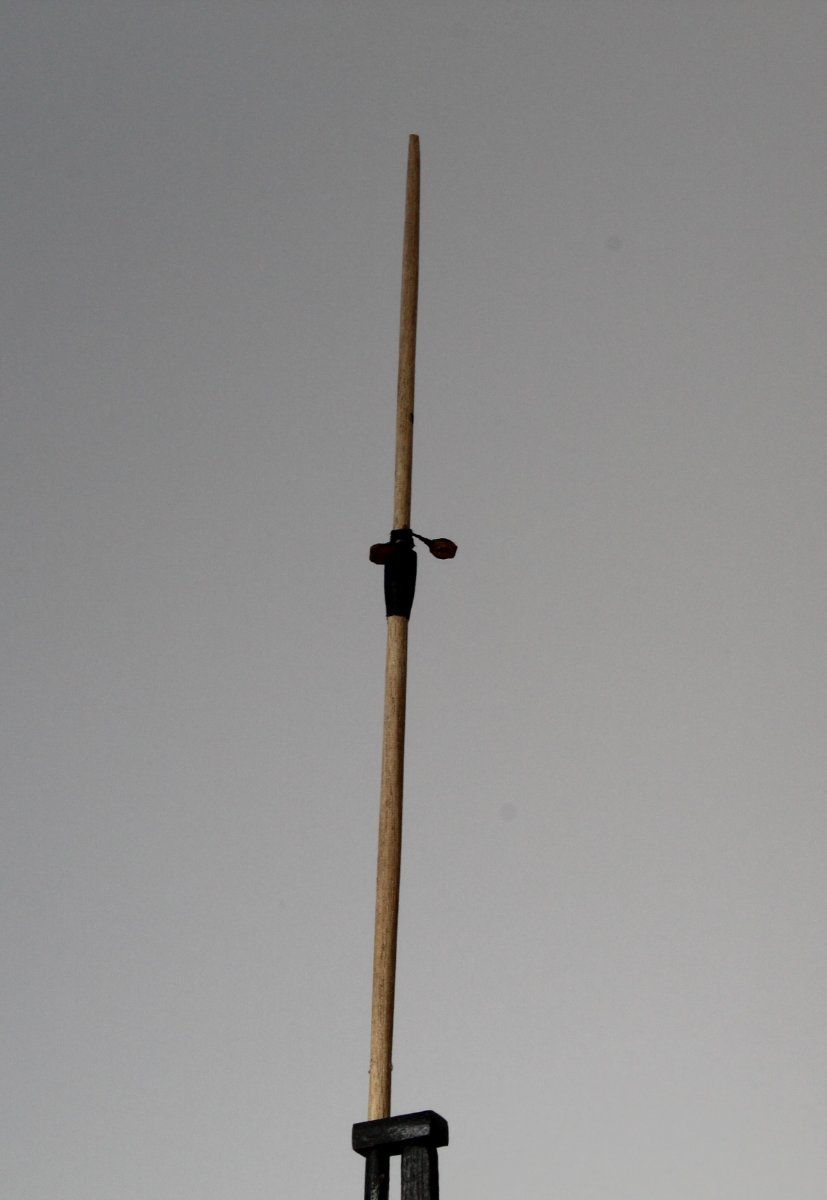
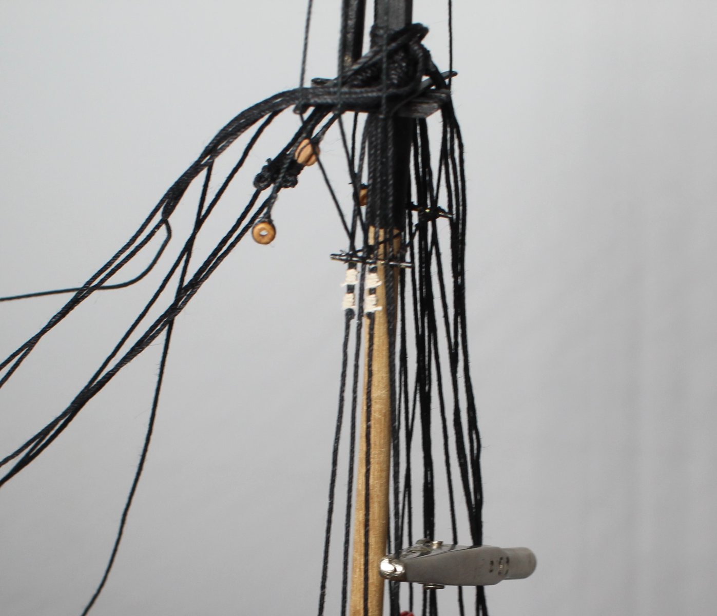
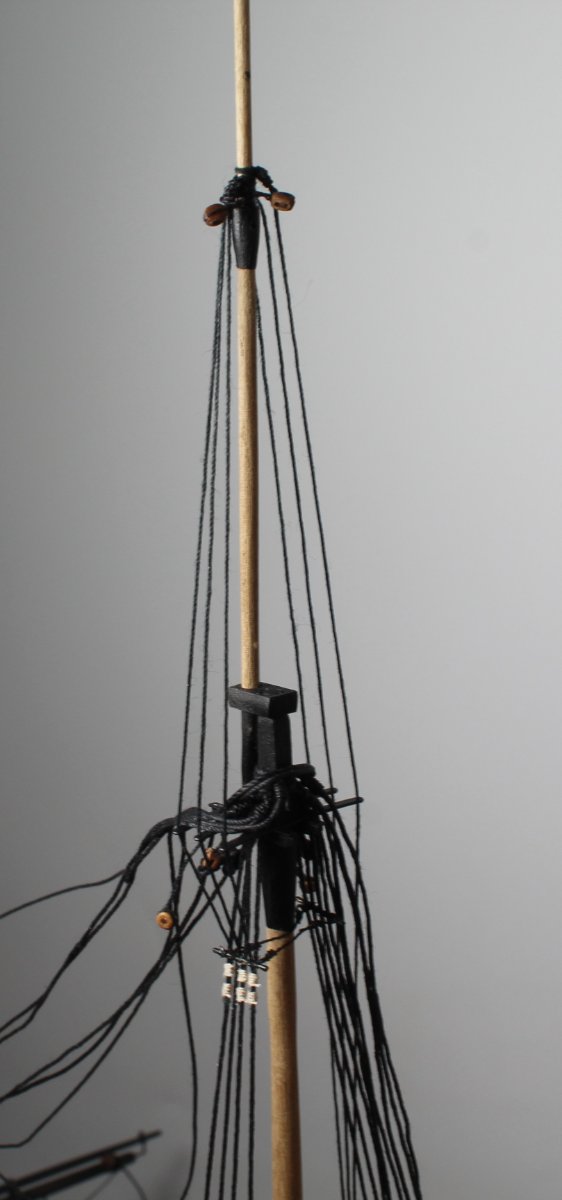
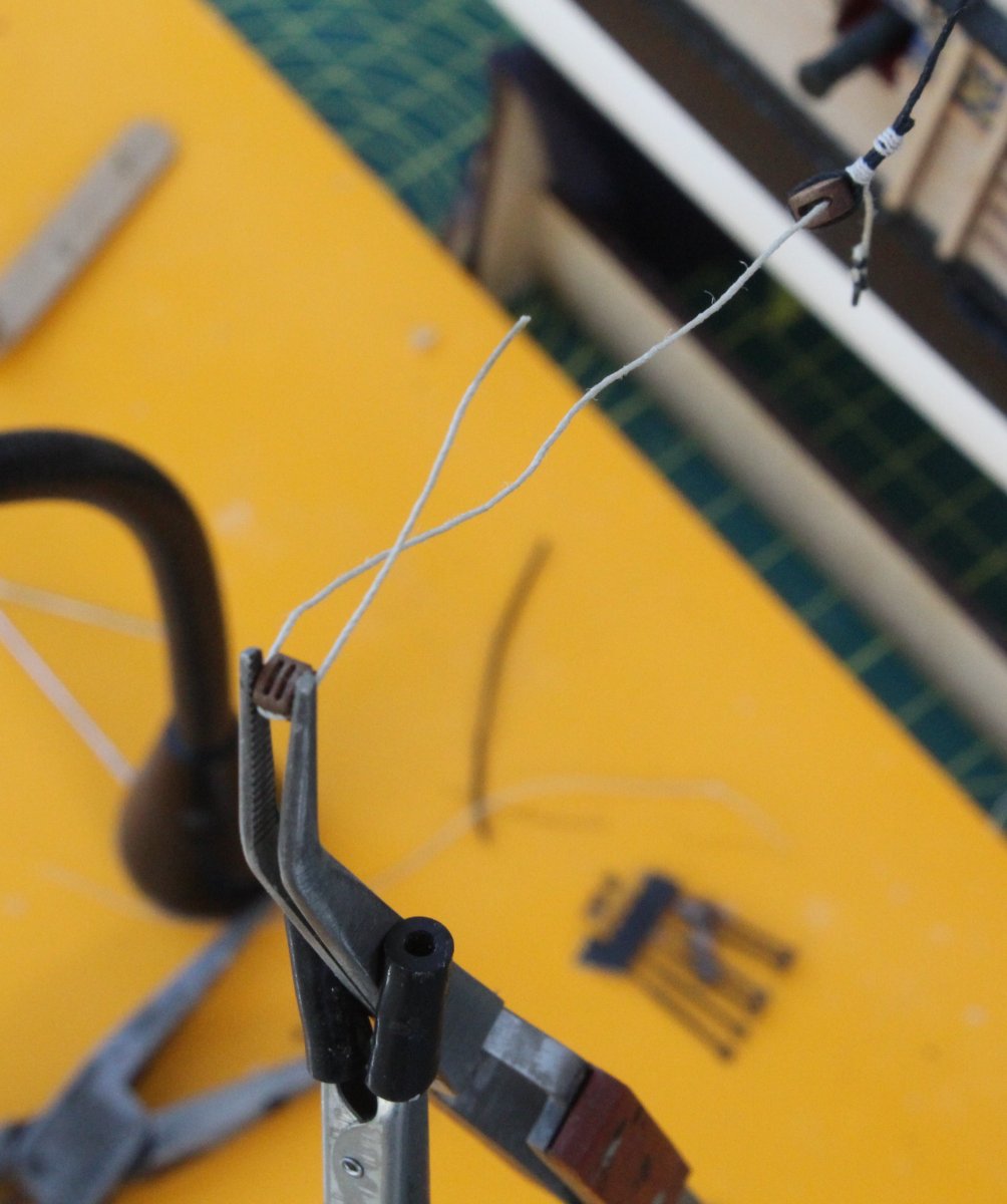
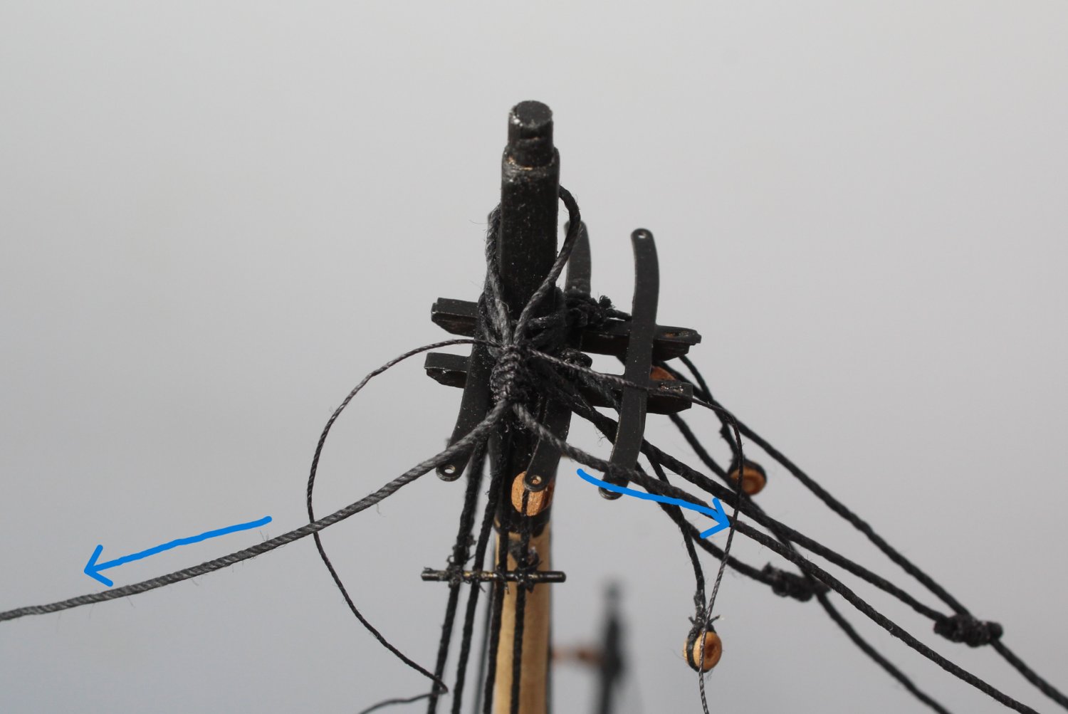
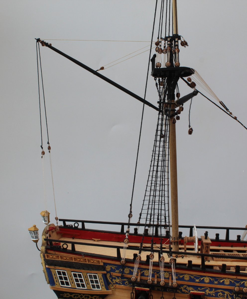
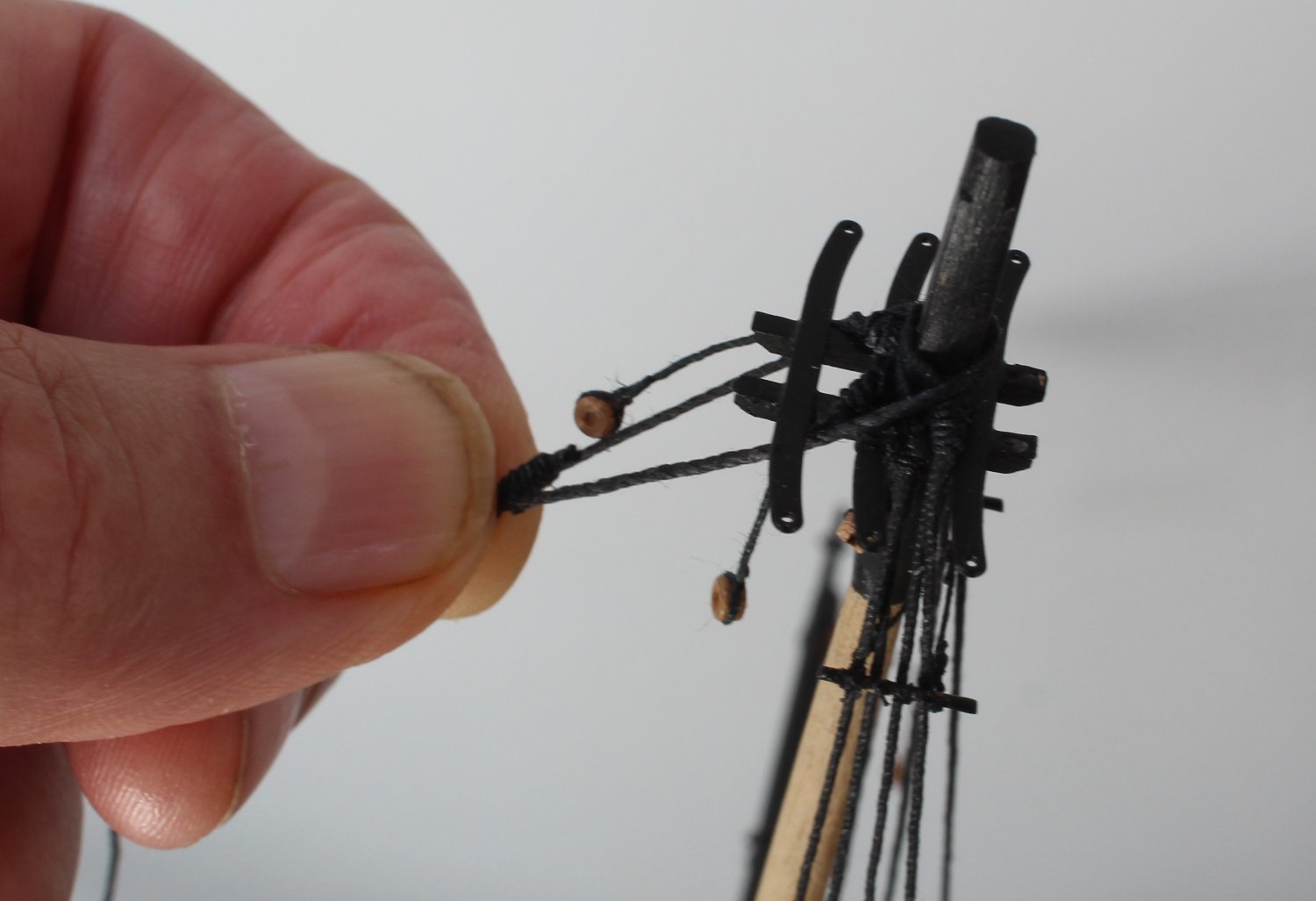
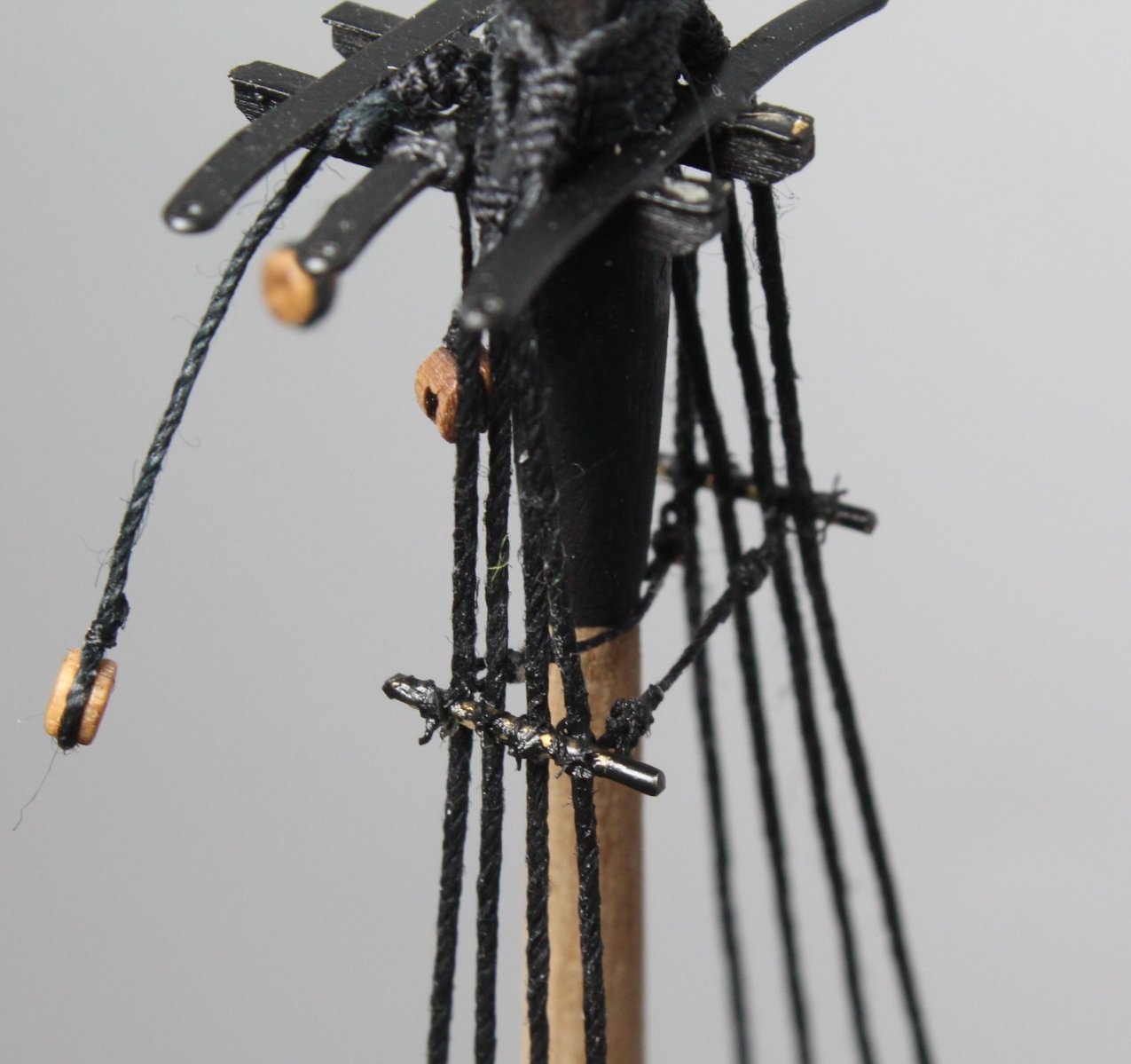
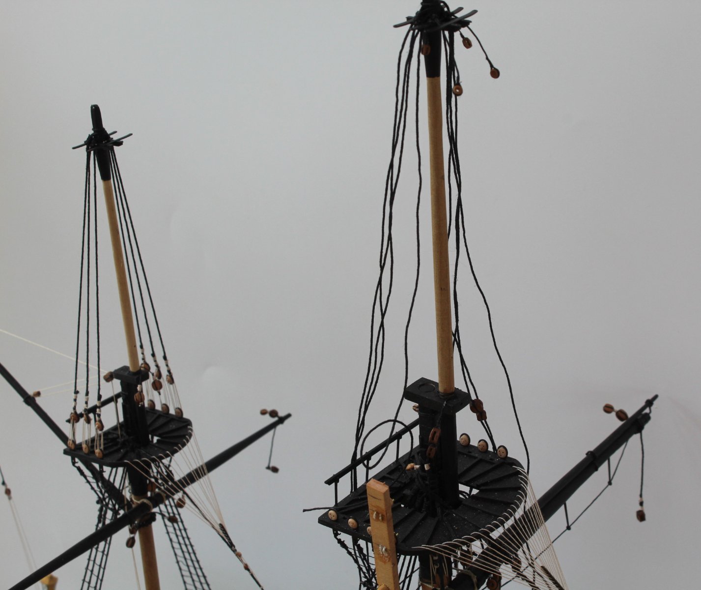
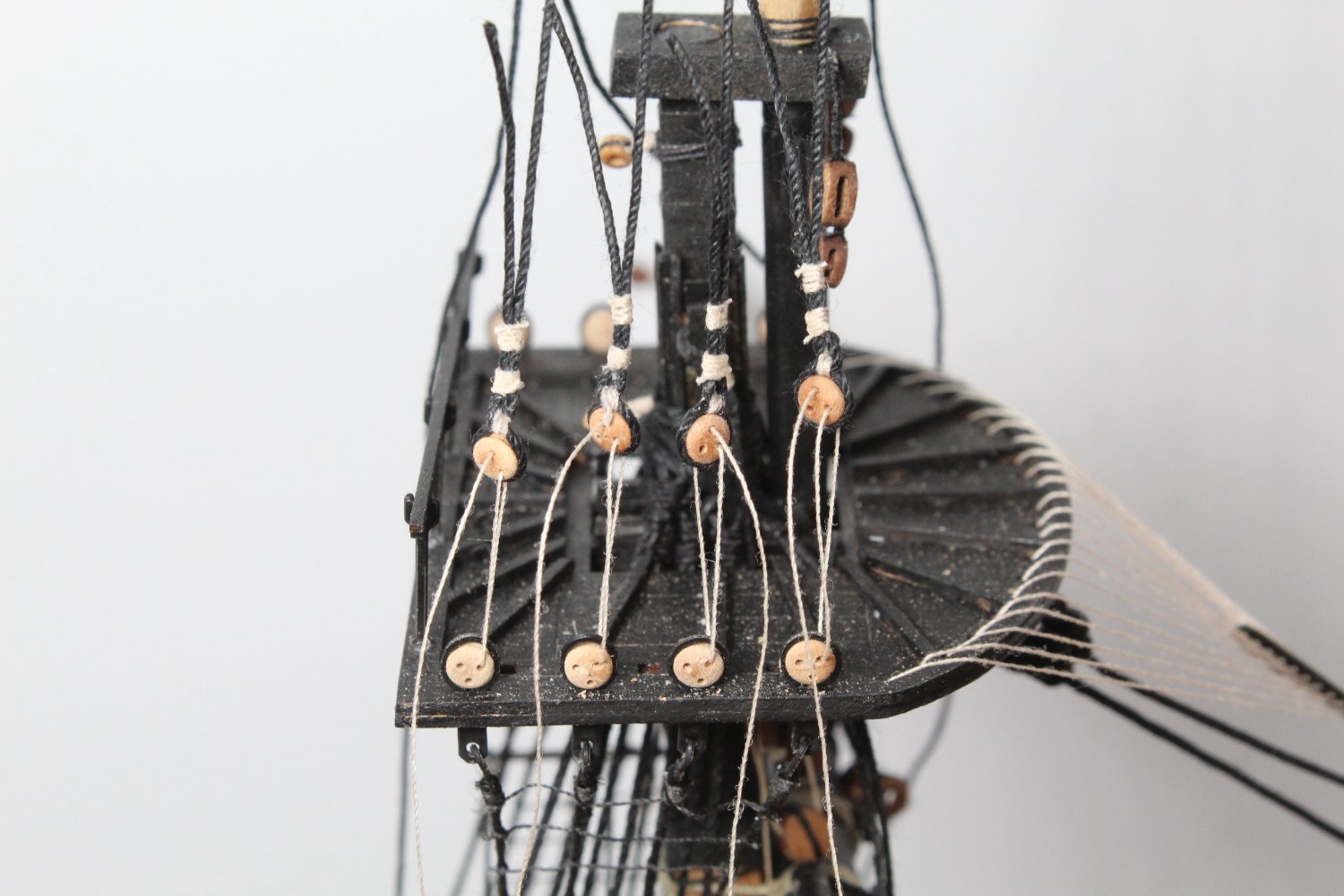
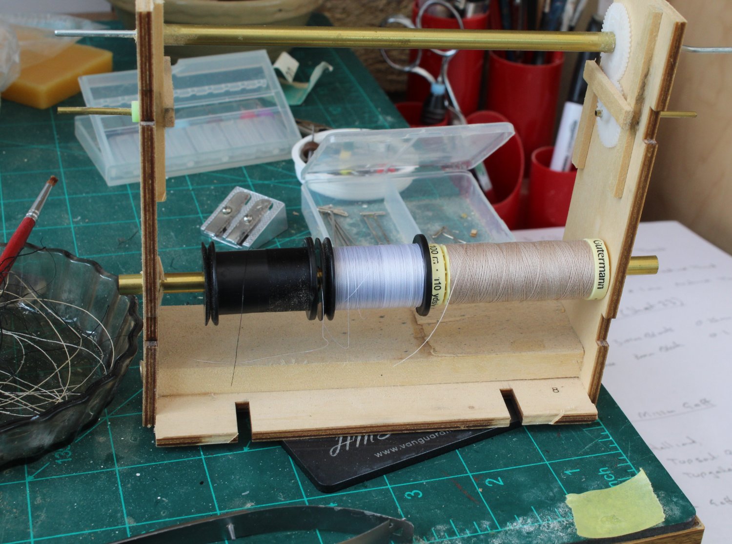
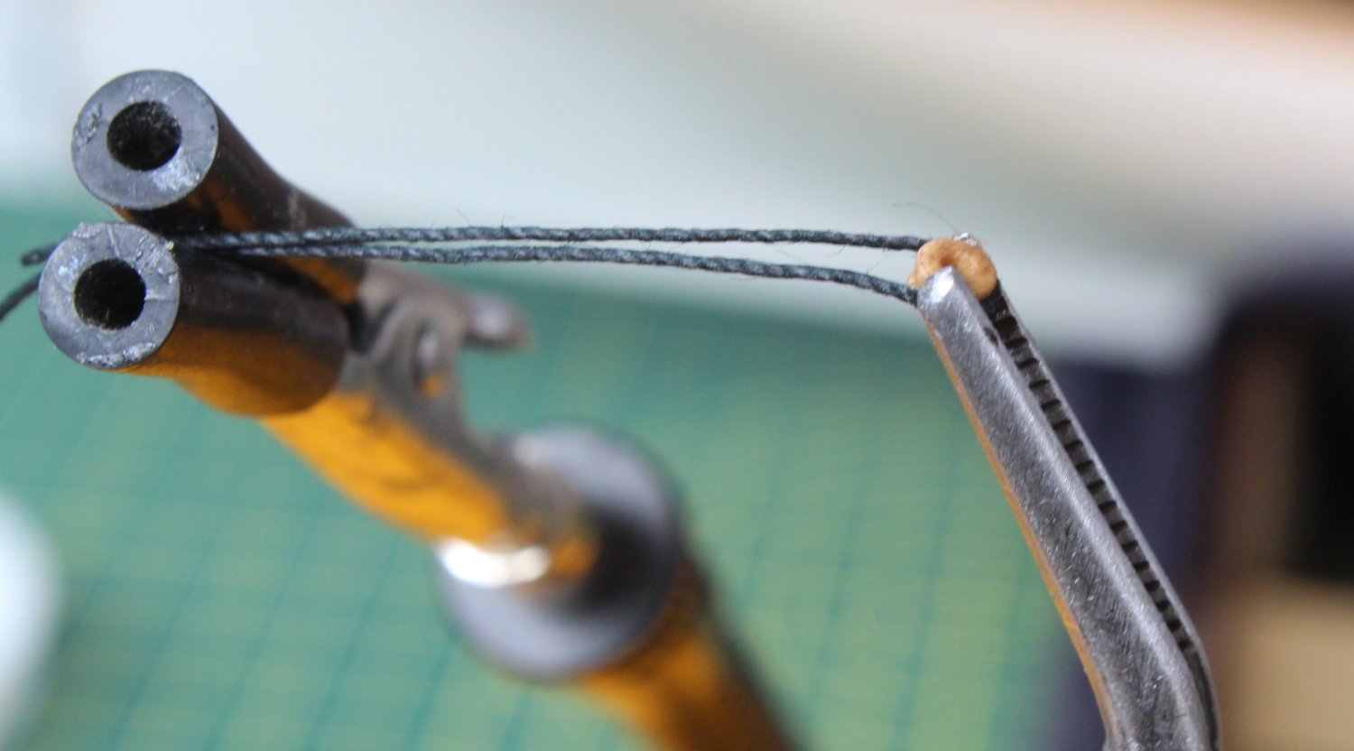
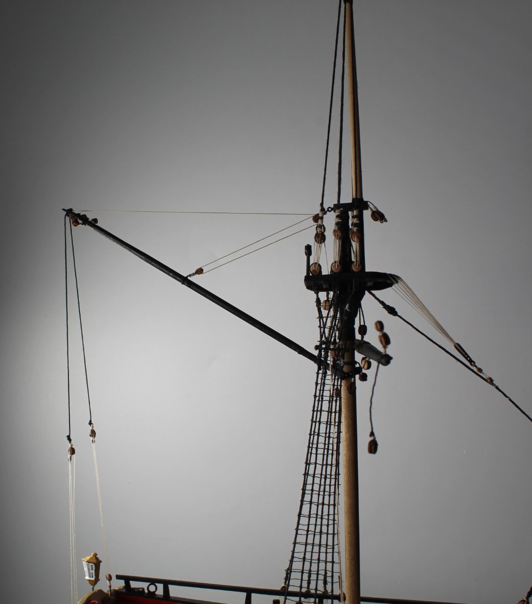
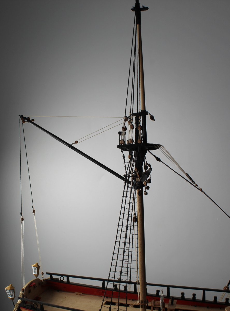
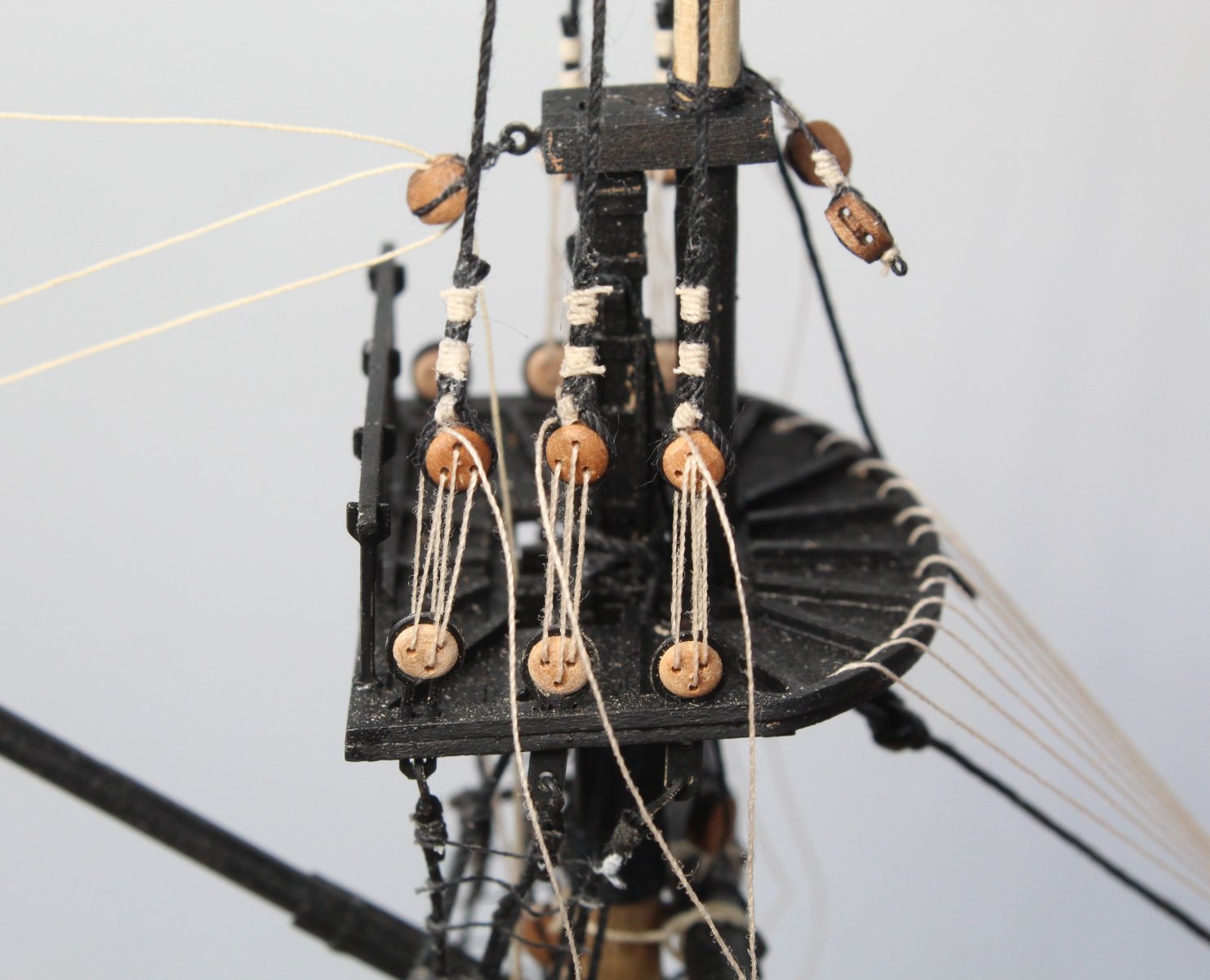
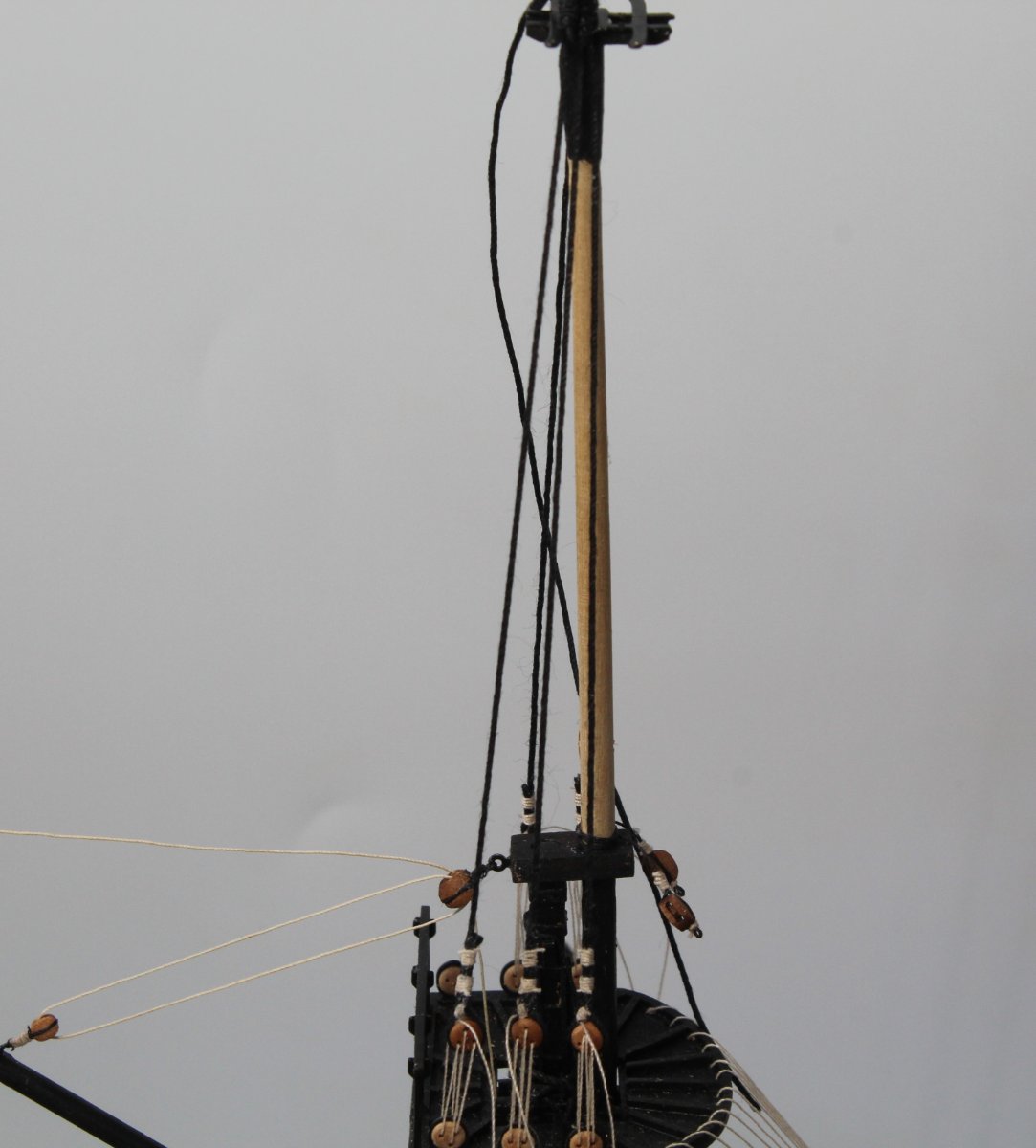
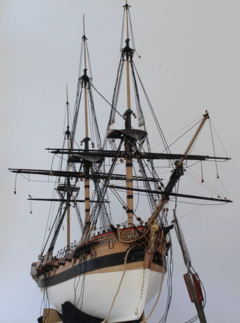
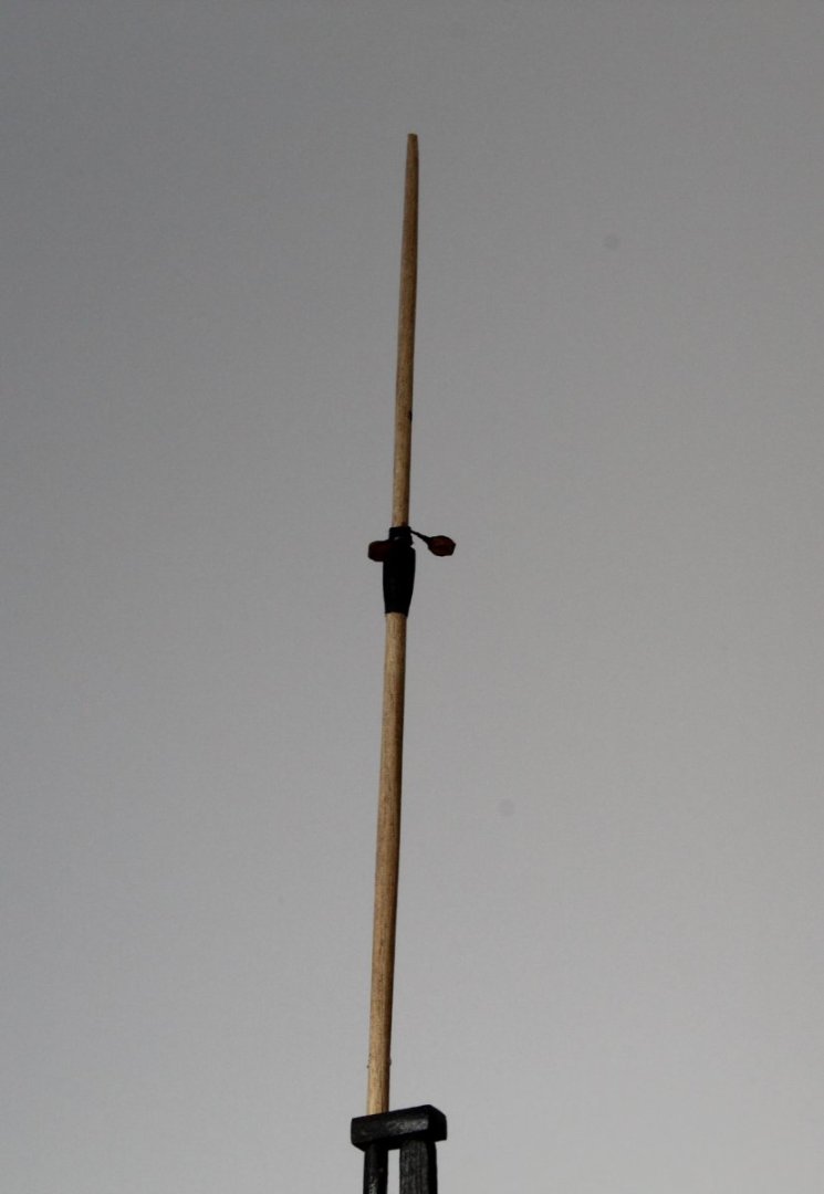
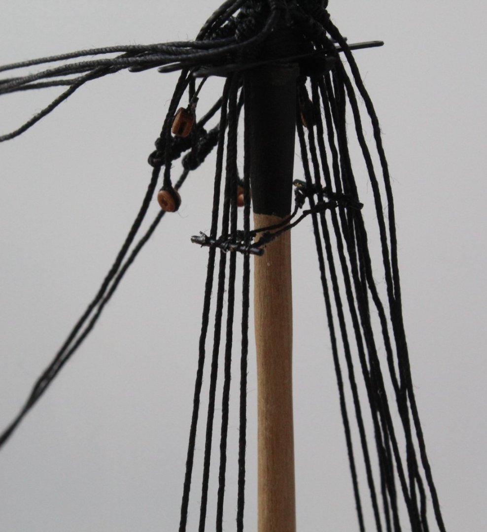
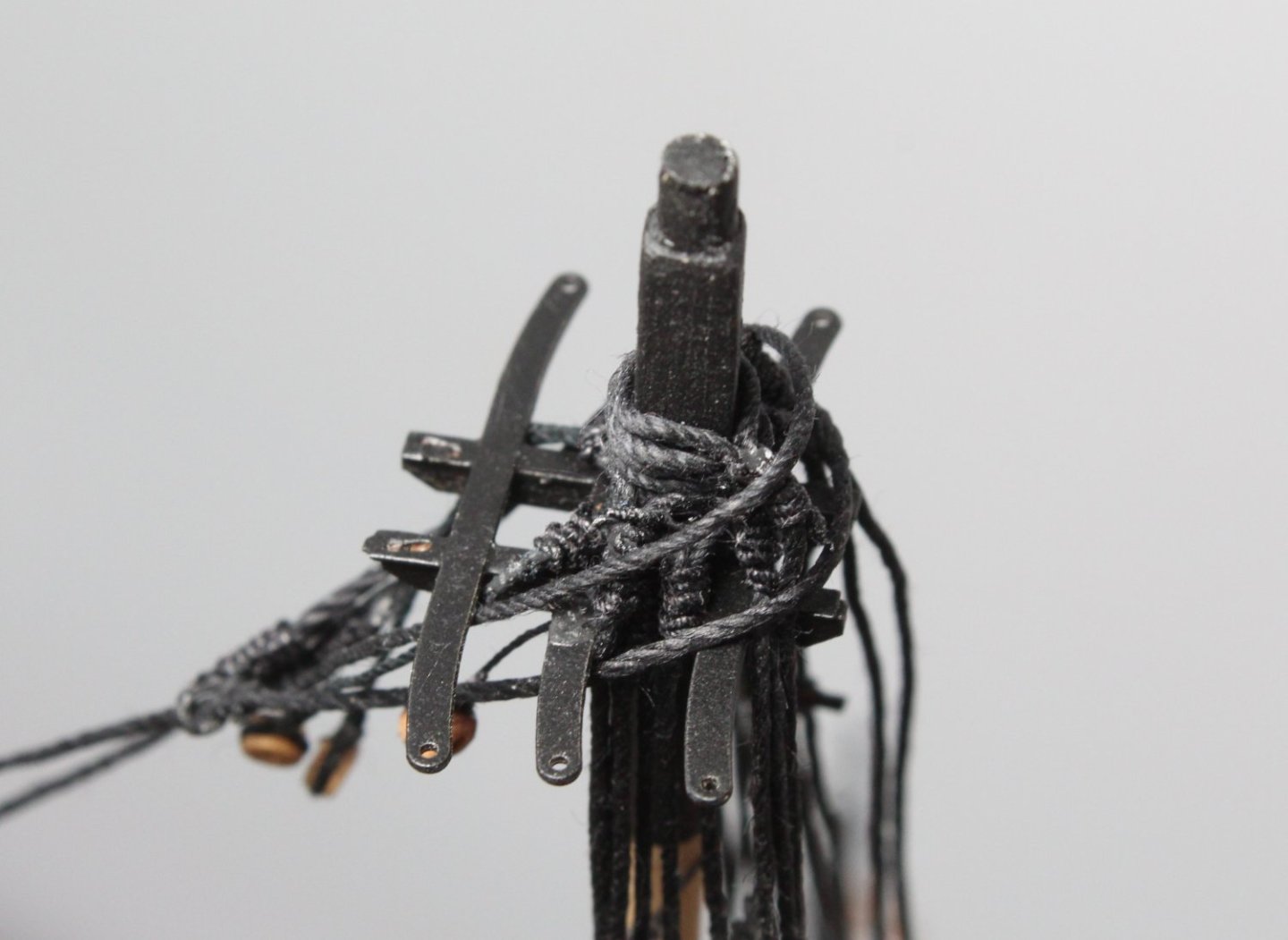
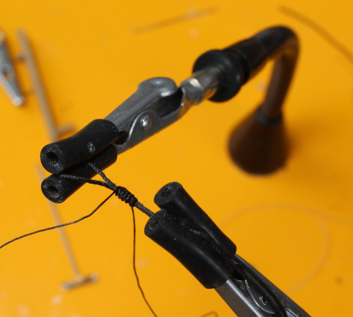
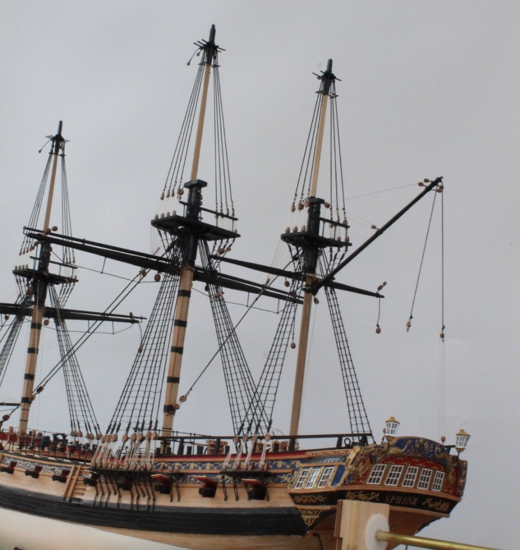
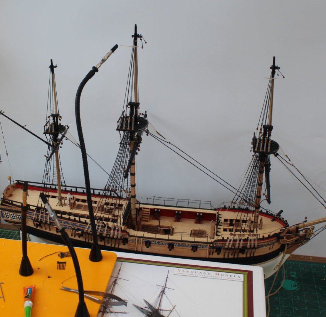
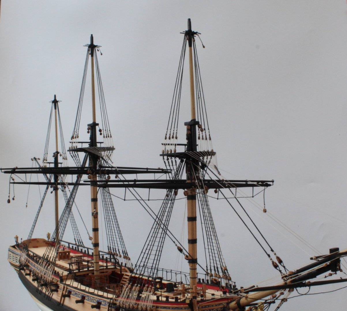
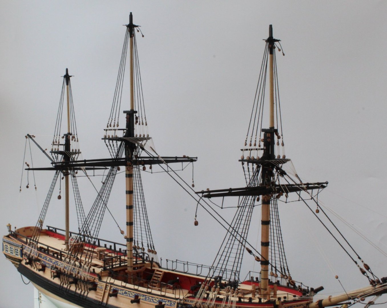
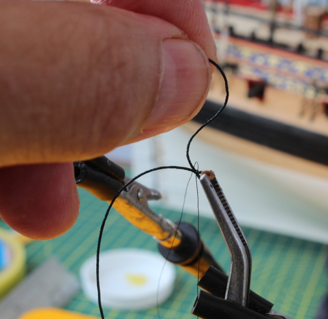
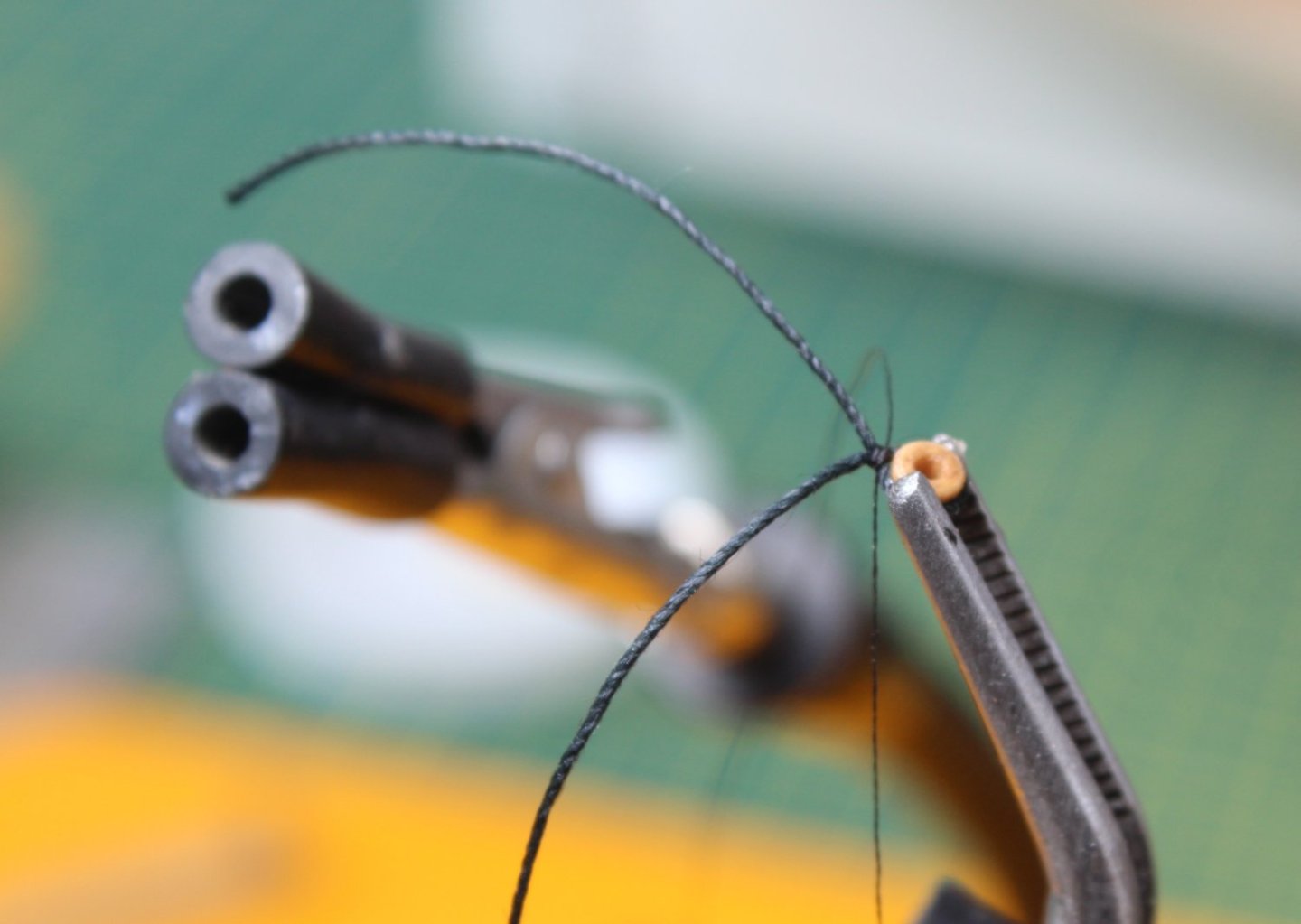
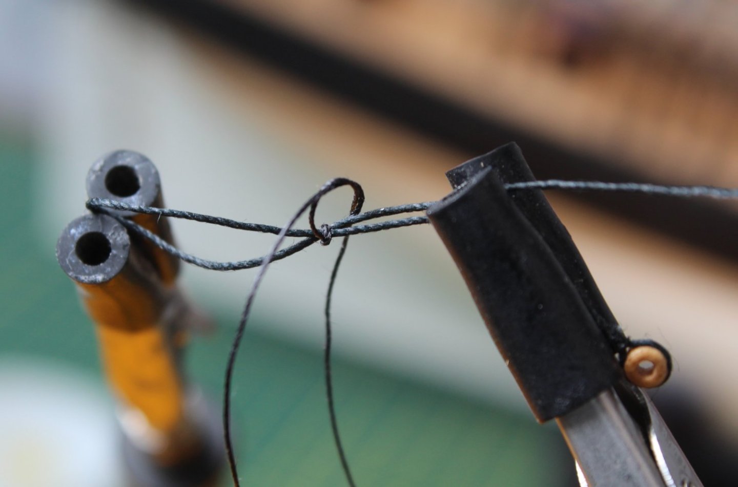
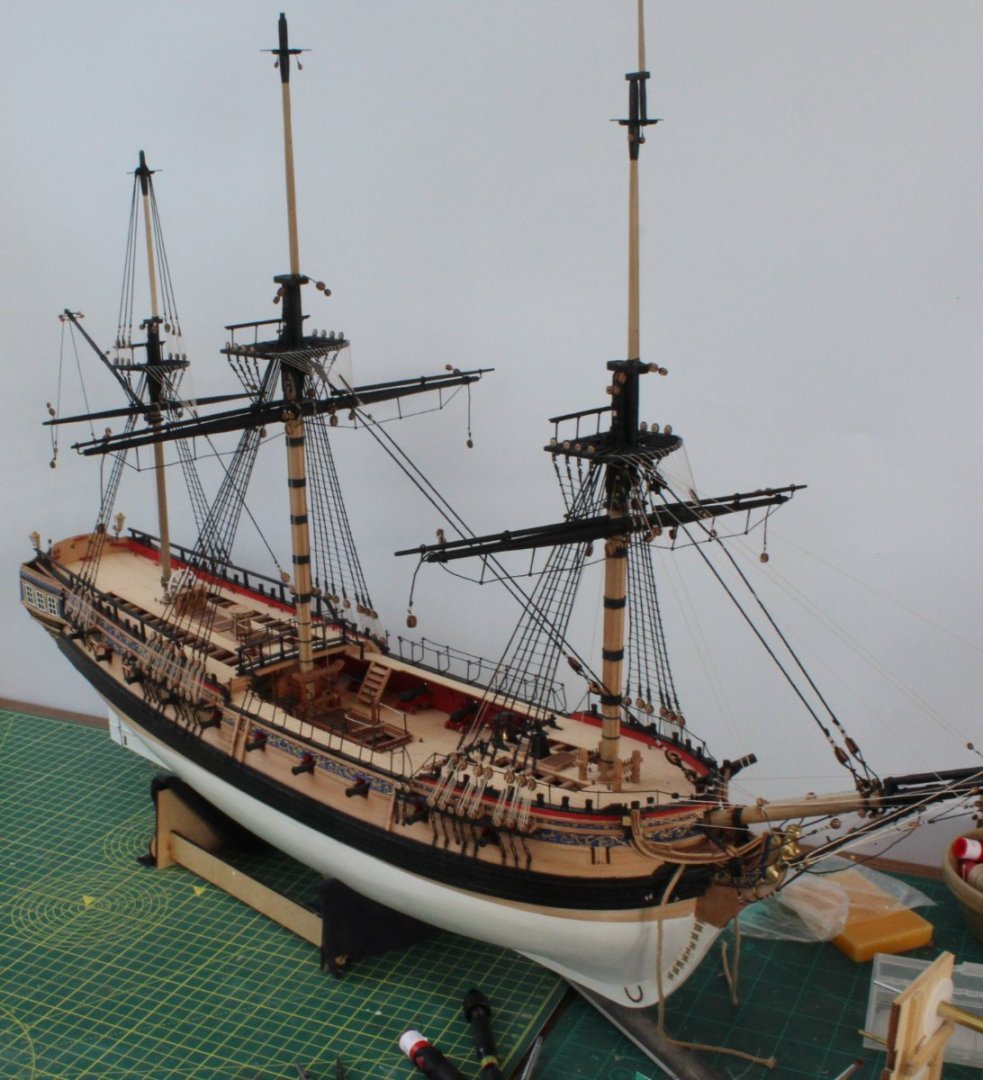
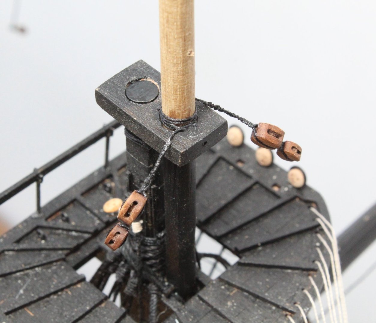
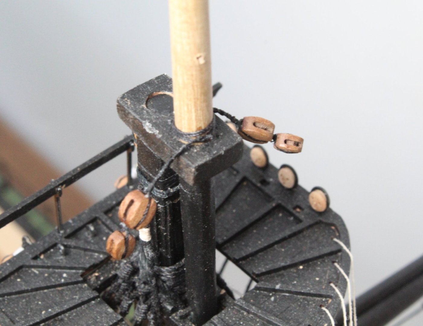
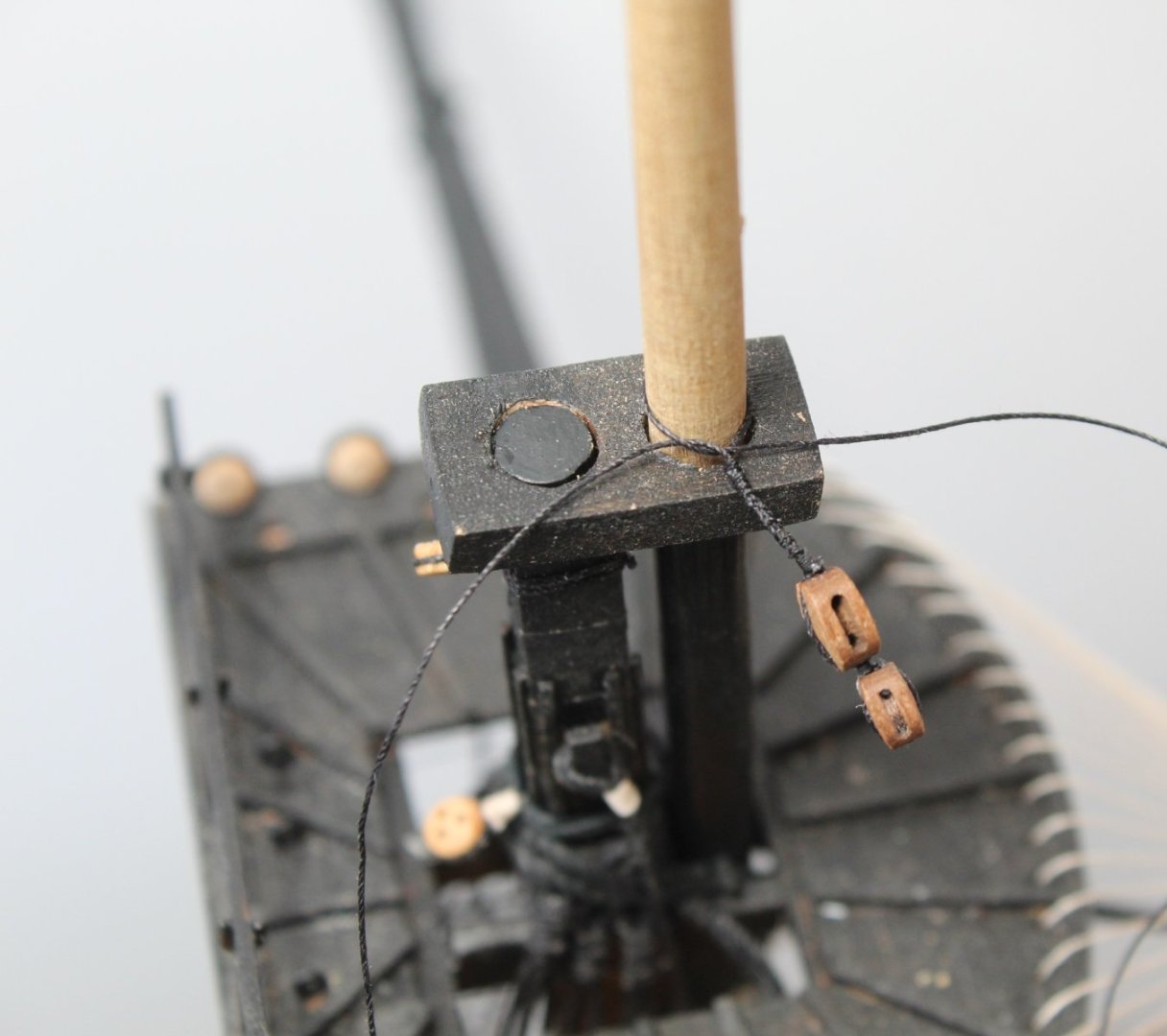
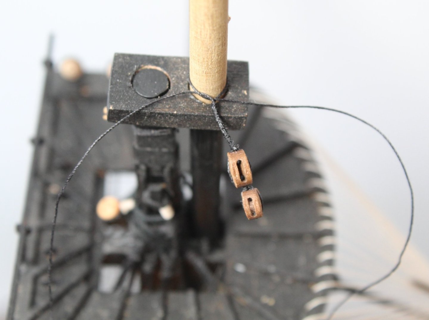
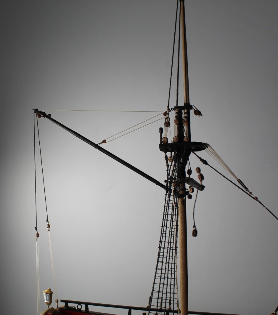
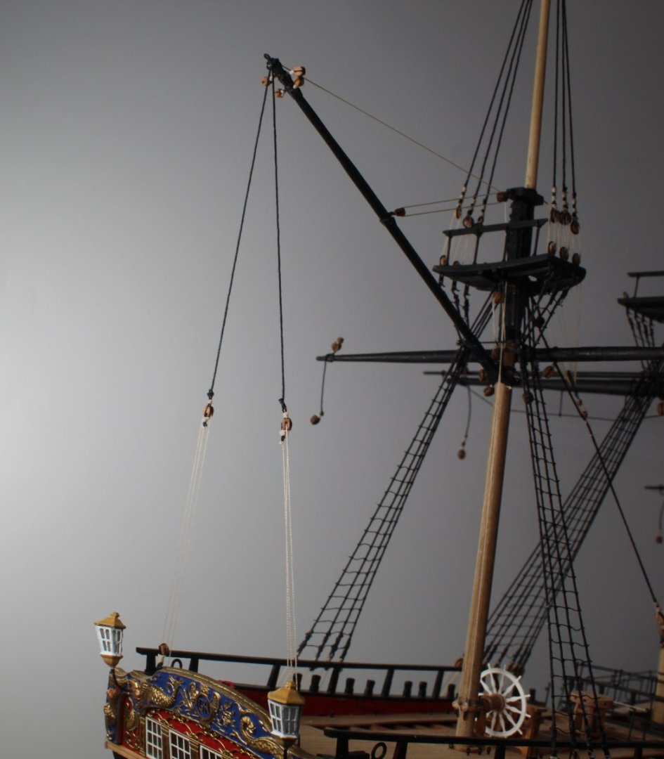
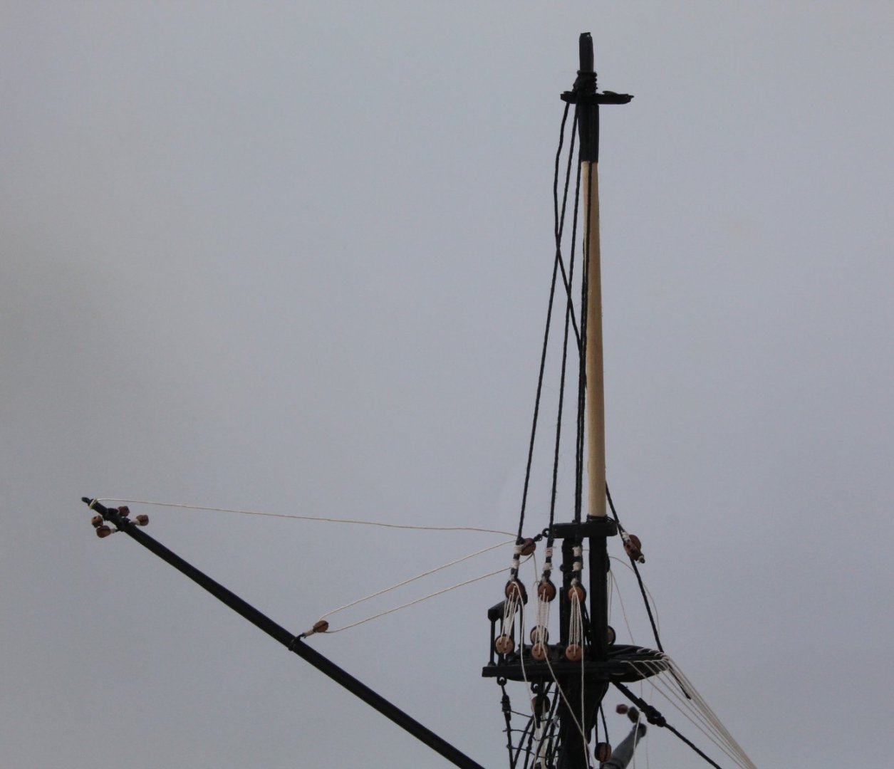
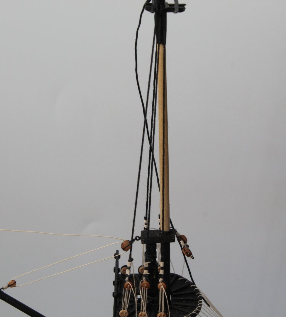
 Topgallant Shrouds - Completed This will be my last post for a few days as our youngest grandson (14 month old) is coming to stay for a few days. I have pushed on yesterday and this morning and I was able to complete the work on installing the mizzen, main and fore topgallant masts and their associated shroud lines. For me this represents reaching a major milestone in the build process. There is still quite of lot of work left, but once the topmast ratlines have been added to the shrouds there is, to my mind, light at the end of the tunnel. To celebrate reaching this milestone I treated myself to the Erycina and Saucy Jack Vanguard Model kits (I decided to buy them before the sale end next month) as they will be my next project. The current state of play with my build is that the mizzen topmast backstay and stays have been rigged. All the backstays lines for the main and fore topmasts have been added but they have not been rigged to their respective deadeyes / blocks. The main and fore topmast stays have also been added to their respective topmasts and are ready to be belayed. Before I complete the rigging work on the topmast backstays and stays I need to add the ratlines to the topmast shrouds. This should take me 3 or 4 days to complete, once I can resume work in the shipyard, probably on Friday unless I can sneak the odd hour or two in when the little chap is napping. In the picture below the tweezers are adding a bit of tension to the fore topmast stay and preventor free ends.
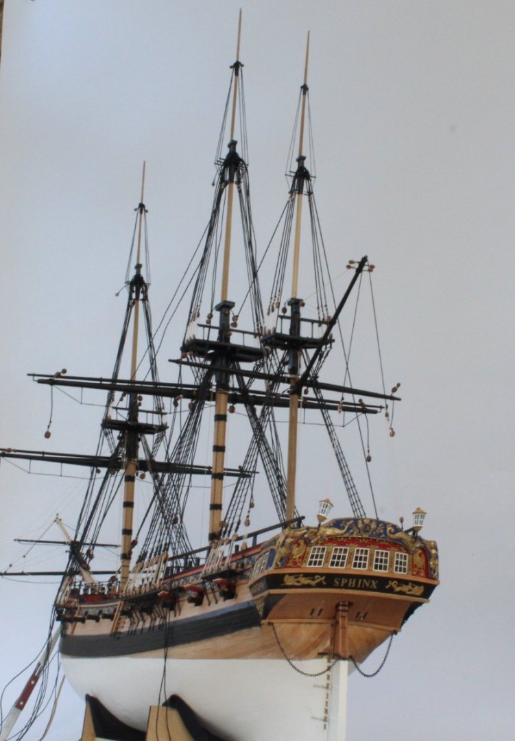

- 476 replies
-
- 11
-

-
- sphinx
- vanguard models
- (and 1 more)
-
A nice looking "mess" Rusty, well done.
-
Hello Mark I have painted holes before fitting items on previous builds and suffered the same problem. I have been much more careful with this build in that respect Fingers crossed I have had my last slice of humble pie on this build. Glenn
- 476 replies
-
- 2
-
-
- sphinx
- vanguard models
- (and 1 more)
-
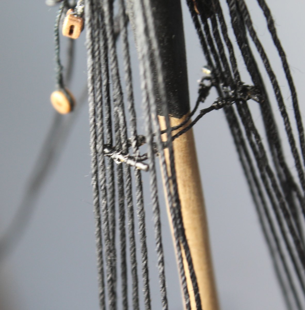
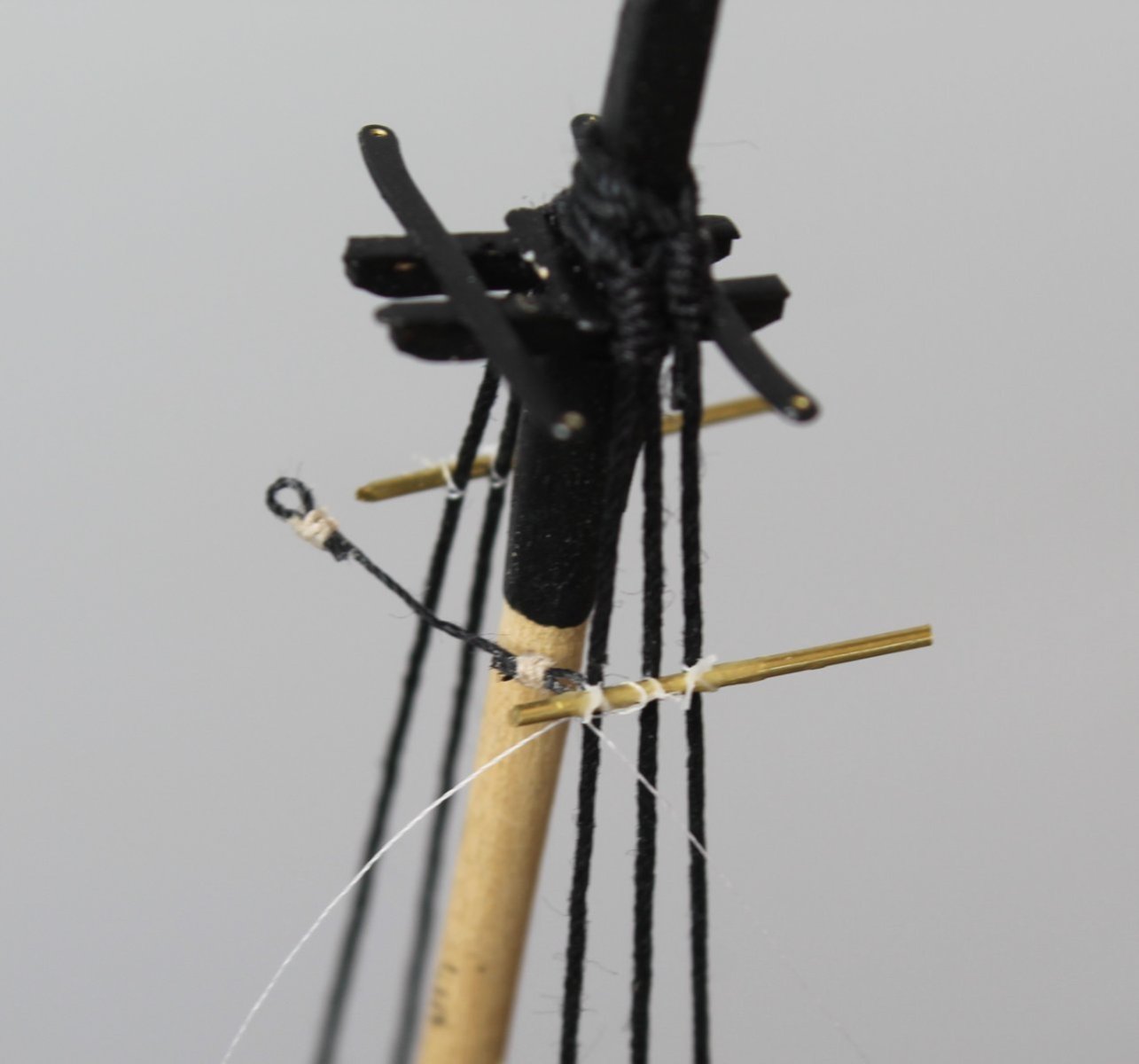
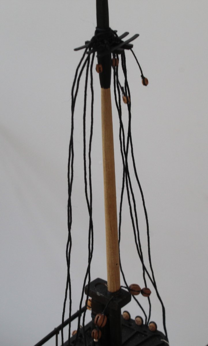
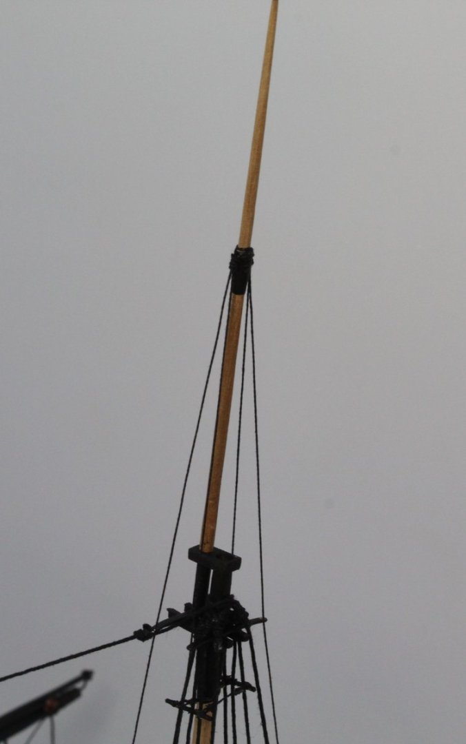
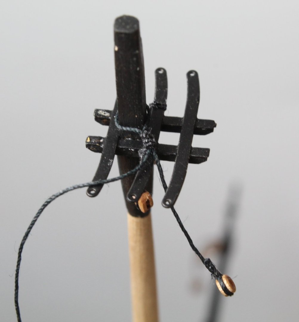
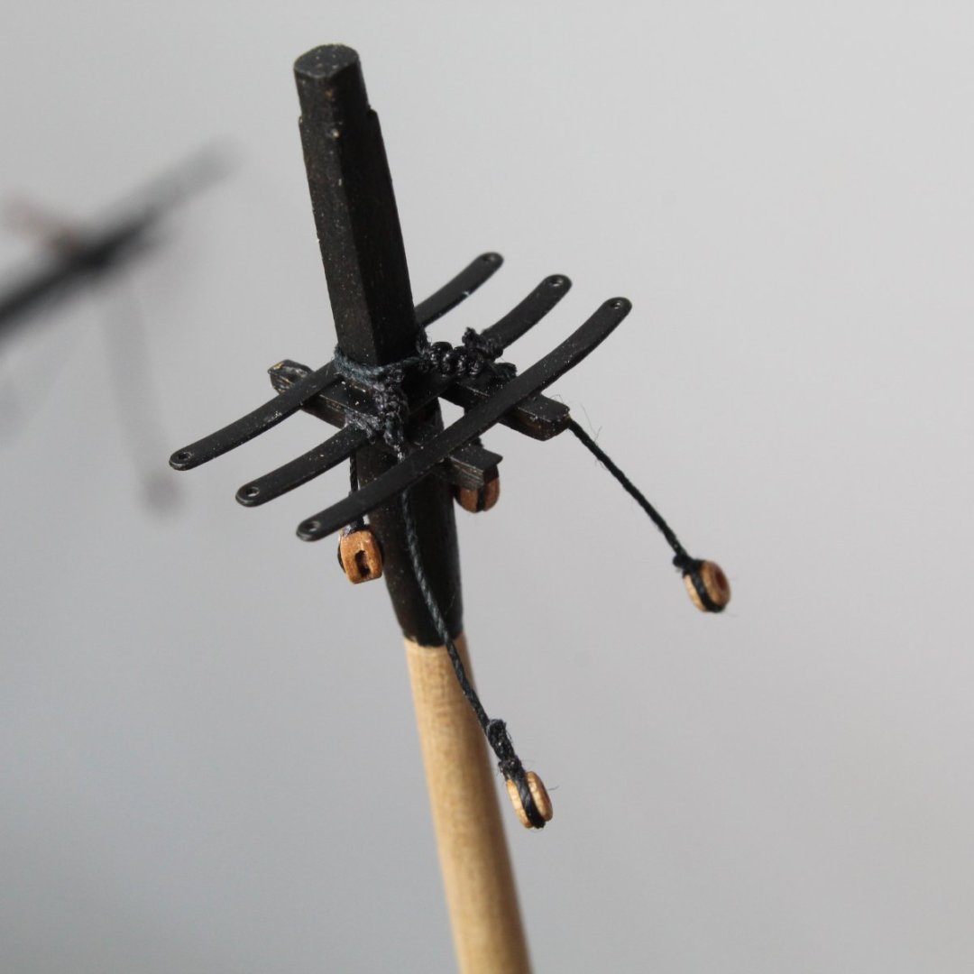
Topgallant Mizzen and Main Masts Moving forward, after my mistake with adding the backstays to soon, I added the topgallant masts (Mizzen and Main). The fore topgallant mast will be fitted later. With the mizzen topgallant mast in place the two shroud lines were added. I decided to hold the shroud line under a bit of tension to help drop out the kinks before adding the seizing. The main topgallant mast has also been fitted. The next photo shows the Sphinx on the work bench. Holding the mizzen lines under some tension did help remove the kinks in the shrouds. It was a relatively simply task to add the seizing. Moving on to the main topgallant mast shrouds. The previously added backstay shrouds were moved out of the way and the shrouds were seized to the topmast shrouds. Once the shroud is run in I use a croc clip to hold the shroud in place to enable to seizing to be added, as can be seen in the photo below. The end result I will need to repeat the above for the starboard side mizzen and main topgallant shrouds. Not sure when I will get time to do this as our youngest grandson (aged 14 months) is coming to stay for a few nights.


- 476 replies
-
- 4
-
-
- sphinx
- vanguard models
- (and 1 more)
-
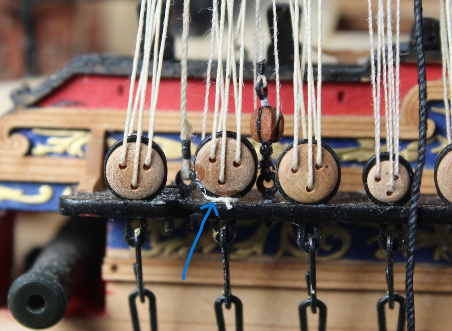
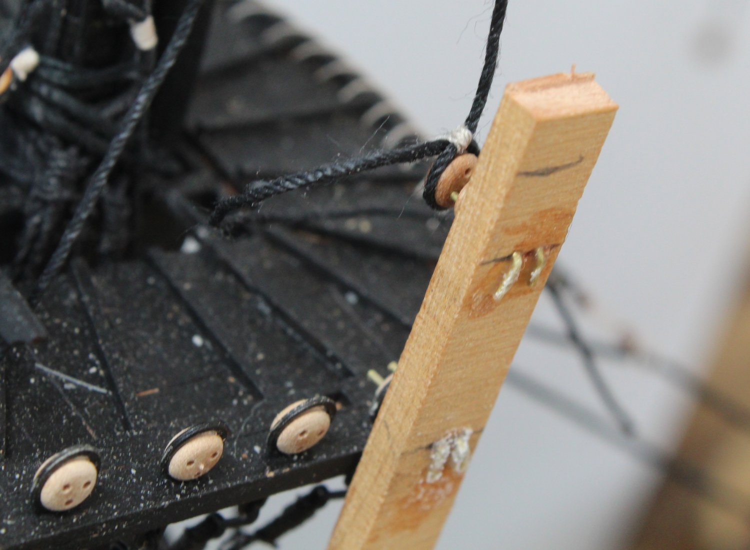
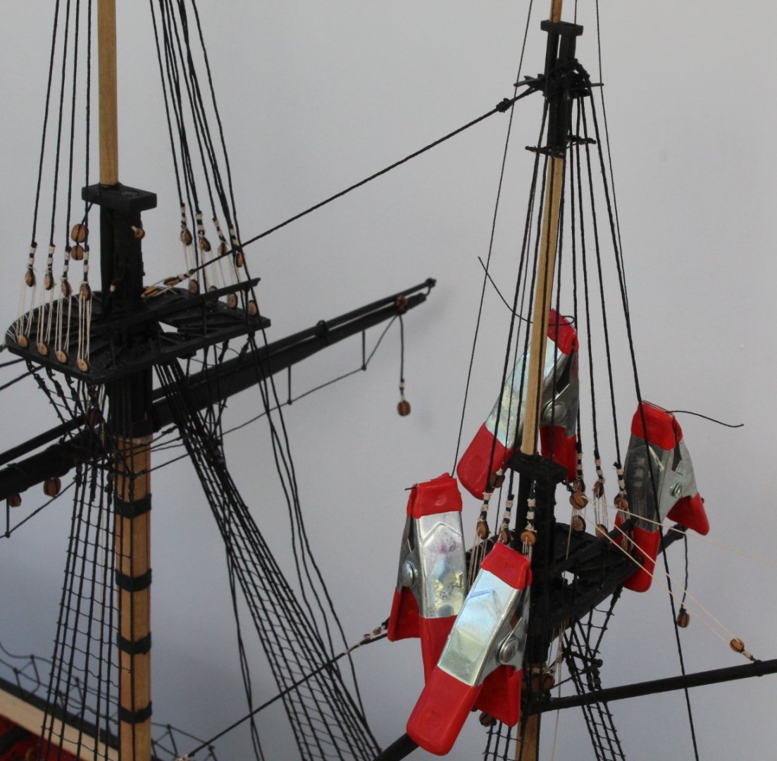
Award for Numpty (Idiot) of the Week Goes To Glenn (A Multiple Numpty Award Winner) One thing I have tried to do with the rigging is to plan ahead so that the process can be as easy as possible and to avoid trying to add rigging in congested areas. With that in mind I decided it would be beneficial to add the main backstays as the access is much better without the topgallant mast in place. With the backstay shrouds in place it seemed to make sense to rig them. As detailed in my last post I forged ahead and completed the main breast backstay. I had also started work on adding the main shifting backstay. I was very happy with the progress I was making. Yesterday evening, when looking at my model, after adding the first part of the shifting backstay rigging I suddenly realised the error of my ways. I had not considered two outstanding rigging tasks, namely: a) Adding the ratlines to the topmast shrouds b) Belaying the topgallant mast shrouds to the topmast shrouds just below the topmast futtock stave. As can been seen in the picture below the main breast backstay sits just in front of the futtock stave and this would make belaying the topgallant mast shroud lines very awkward. Furthermore, as can be seen in the next photo, with the backstays in place it would also greatly hinder the access when adding the ratlines. I knew the backstay rigging had to be removed. So this morning with a little bit of gentle pressure I was able to: a) remove the two eyebolts from the channel b) remove the lanyards from the rigged 3mm deadeye lanyards c) remove the rigging belayed around the bottom of the 5mm channel deadeye The picture below shows the backstay rigging has been released. Thankfully I think I can keep the 5mm block and the 3mm deadeye on the end of the backstay shrouds. All the other breast backstay rigging will be removed and redone at a later stage. The unrigged backstay shrouds can be kept and placed and out of the way whilst I add the topgallant mast and topgallant shrouds, as shown in the photo below. With all the shrouds in place the ratlines can be added. Once all that is done the backstays can be rigged. There is a reason the excellent rigging plans and build manual define the required rigging sequence. However numptys like me think they know much better than the experts (sorry @chris watton and @James H). Lesson learnt and I am now going to eat a large slice of humble pie as contemplate the error of my ways.

- 476 replies
-
- 5
-
-
- sphinx
- vanguard models
- (and 1 more)
-
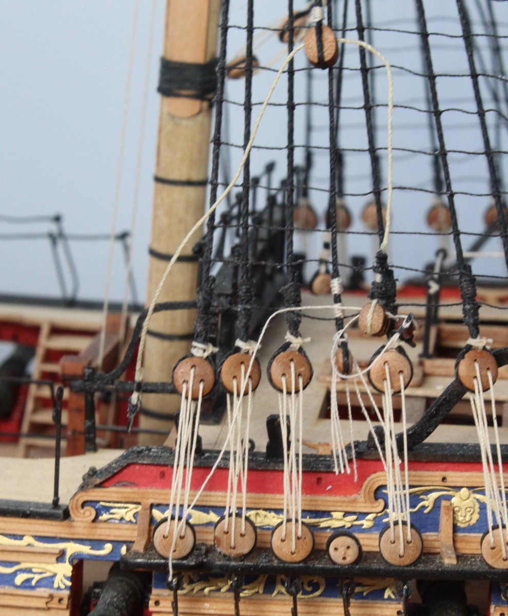
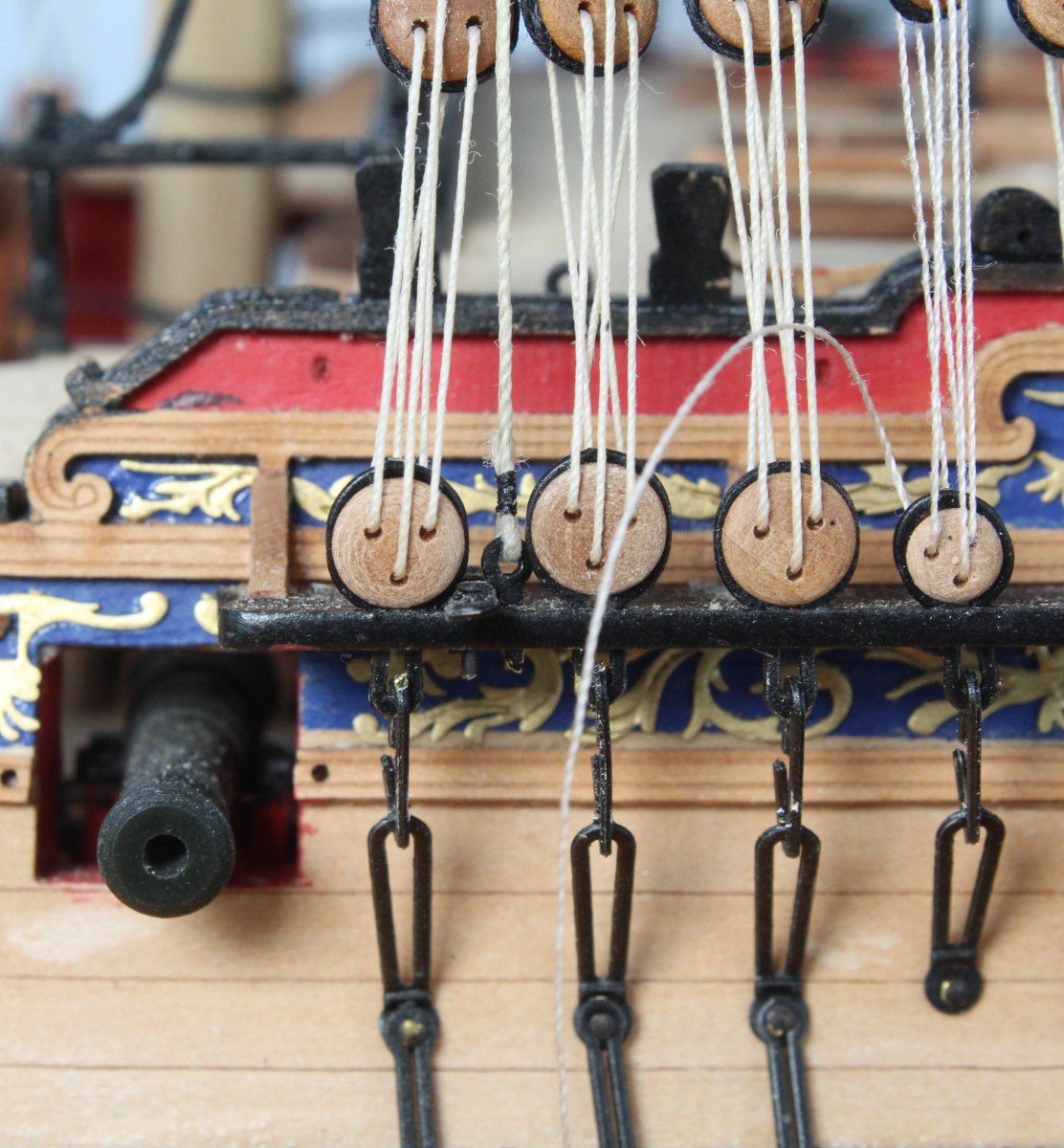
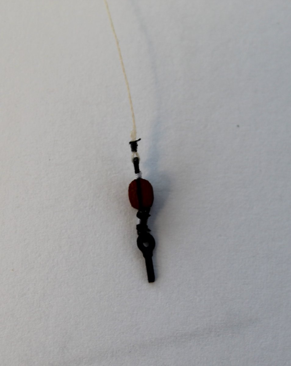
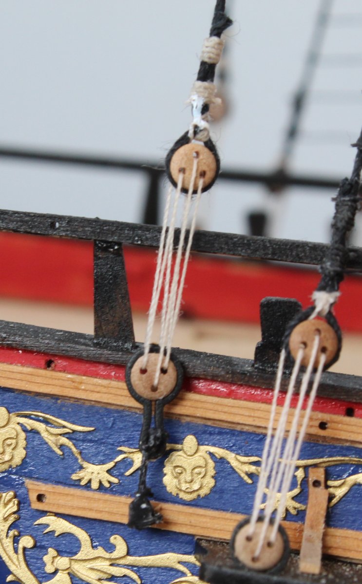
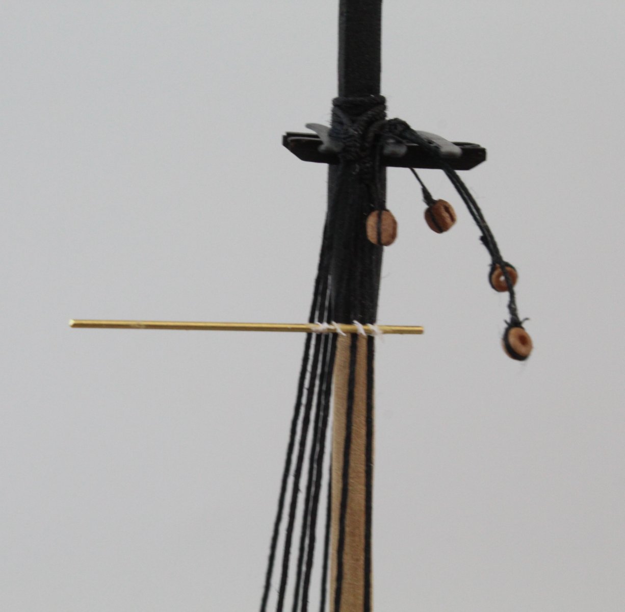
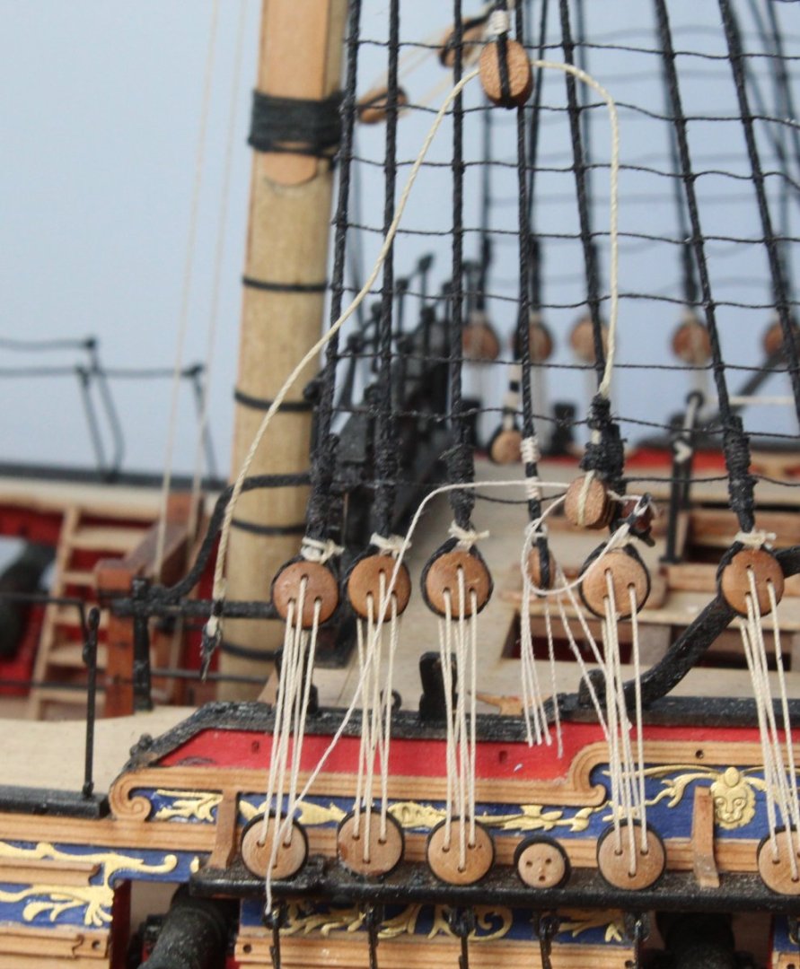
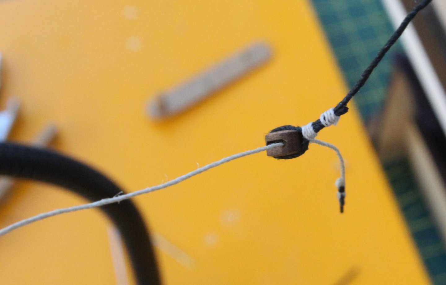
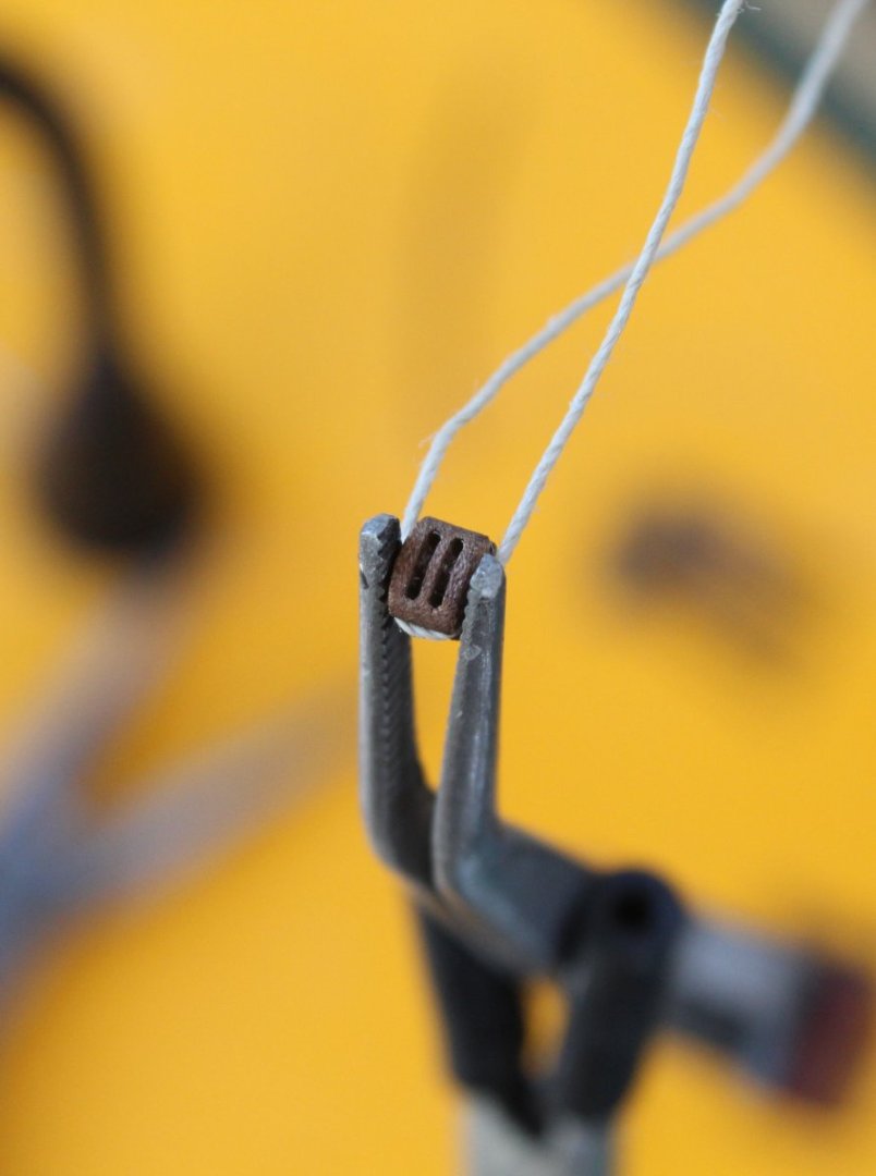
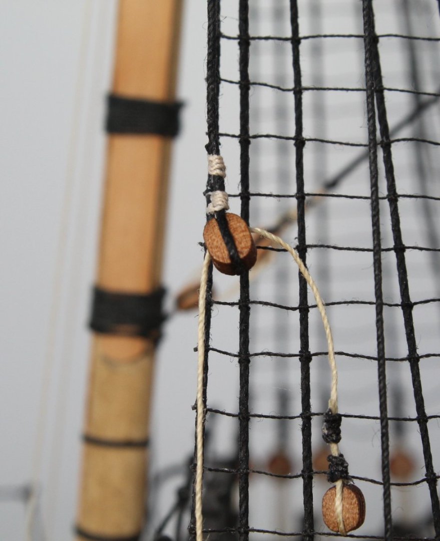
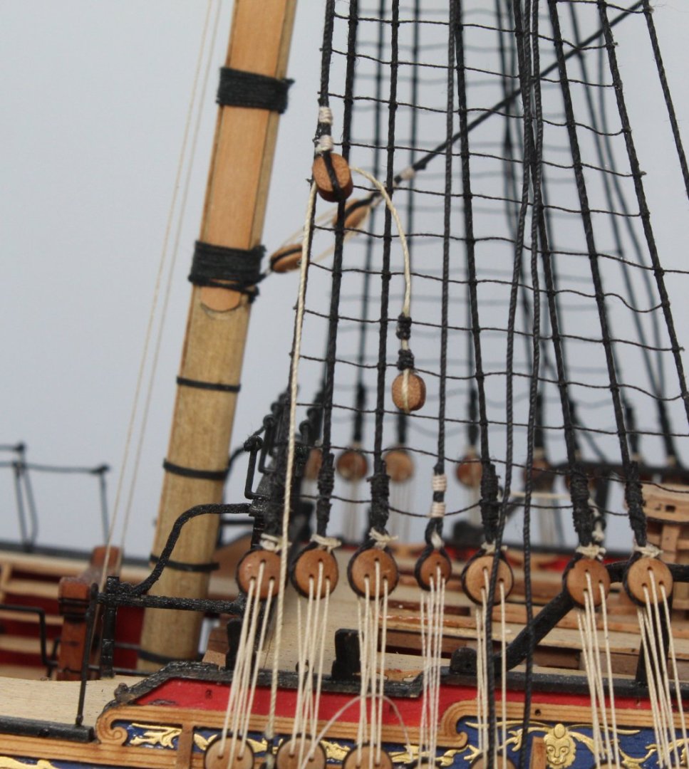
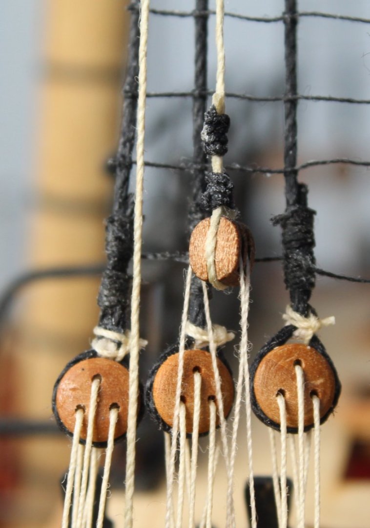
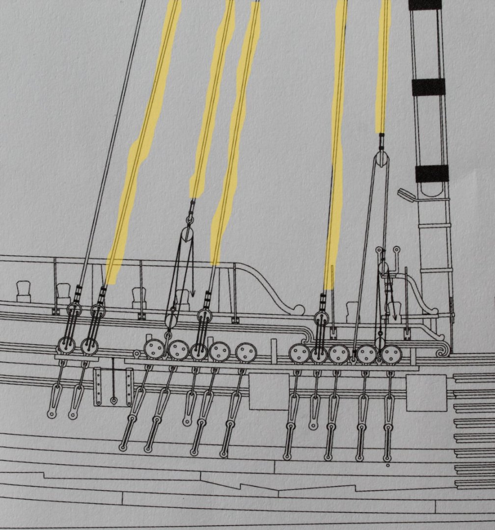
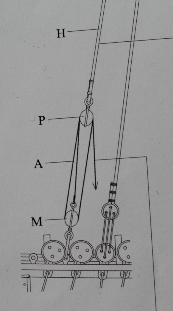
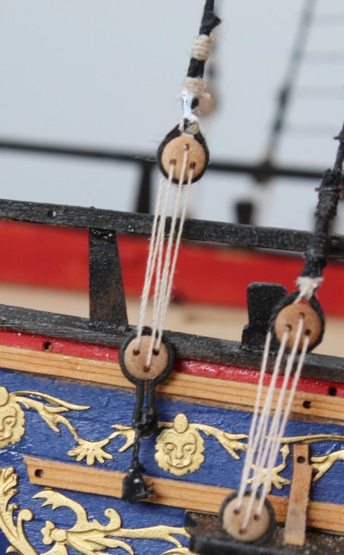
Main Breast Backstay There is quite a bit of work adding the main mast backstays so I will spread the work carried out over different posts. This post will cover the work required to add the Main Breast backstay. There is a shroud pair line and before working on the breast backstay which uses the leading shroud line I decided to rig the other shroud which is a simple deadeye / lanyard arrangement. My aim was to set the 3mm shroud deadeye to the same level as the existing 5mm deadeyes. I was happy that I managed to achieve this, as can be seen below. Moving on to the Main Breast Backstay detail, as can be seen in the rigging plan details shown below this arrangement comprises 3 blocks (5mm single, 4mm double and 3mm single) and two eyelets. Starting with the 5mm single block I seized this to the shroud line, using the lower wrapping on the main mast as the reference point for its position. With that block in place I then took a length of 0.5mm natural thread and added an eyebolt to one end. The thread was then fed through the block as shown in the next photo. With the thread in position I placed the eyelet in the channel (but not glued) and I was able to determine the where I should position the 4mm double block. In my case it was approx. 9cm from the eyebolt seizing. The thread was then removed from the channel and using the 9cm measurement as a guide the 4mm double block was then seized to the free end of the 0.5mm natural thread using the quad hands, I have attached a couple of photos showing the set up I used with the quad hands. The thread is wrapped around the 4mm double block, noting the 9cm distance requirement The next photo is a close up of how I like to hold a block, clamping the thread to prevent unwanted movement, prior to adding the seizing. With the seizing complete I decided I should check the end result so the eyebolt is put back in the channel, but not glued. Ensuring the eyebolt stays in place the position of the 4mm double block can be checked. With everything looking good the next task was to add the second eyebolt to the 3mm single block. When adding the seizing to the 3mm block it was also required to add a thimble to the top end. In the picture below you will note I have already seized a length of 0.1mm natural thread to the thimble. This block arrangement is now ready to be added to the channel. Both the eyebolts were then glued in place and the 0.1mm natural thread was rigged, as per the rigging plans. The free end of the thread is then belayed to the bottom of the nearest lower shroud deadeye, as shown on the photo below The 4mm double block rigged is shown below. The 5mm single block is shown below It proved difficult to take a decent picture showing all the completed rigging, the photo below was the best of a bad bunch. The next post will cover the Main Shifting Backstay rigging process.


- 476 replies
-
- 5
-
-
- sphinx
- vanguard models
- (and 1 more)
-
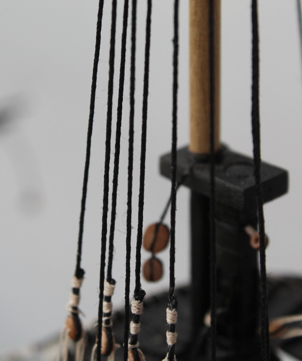
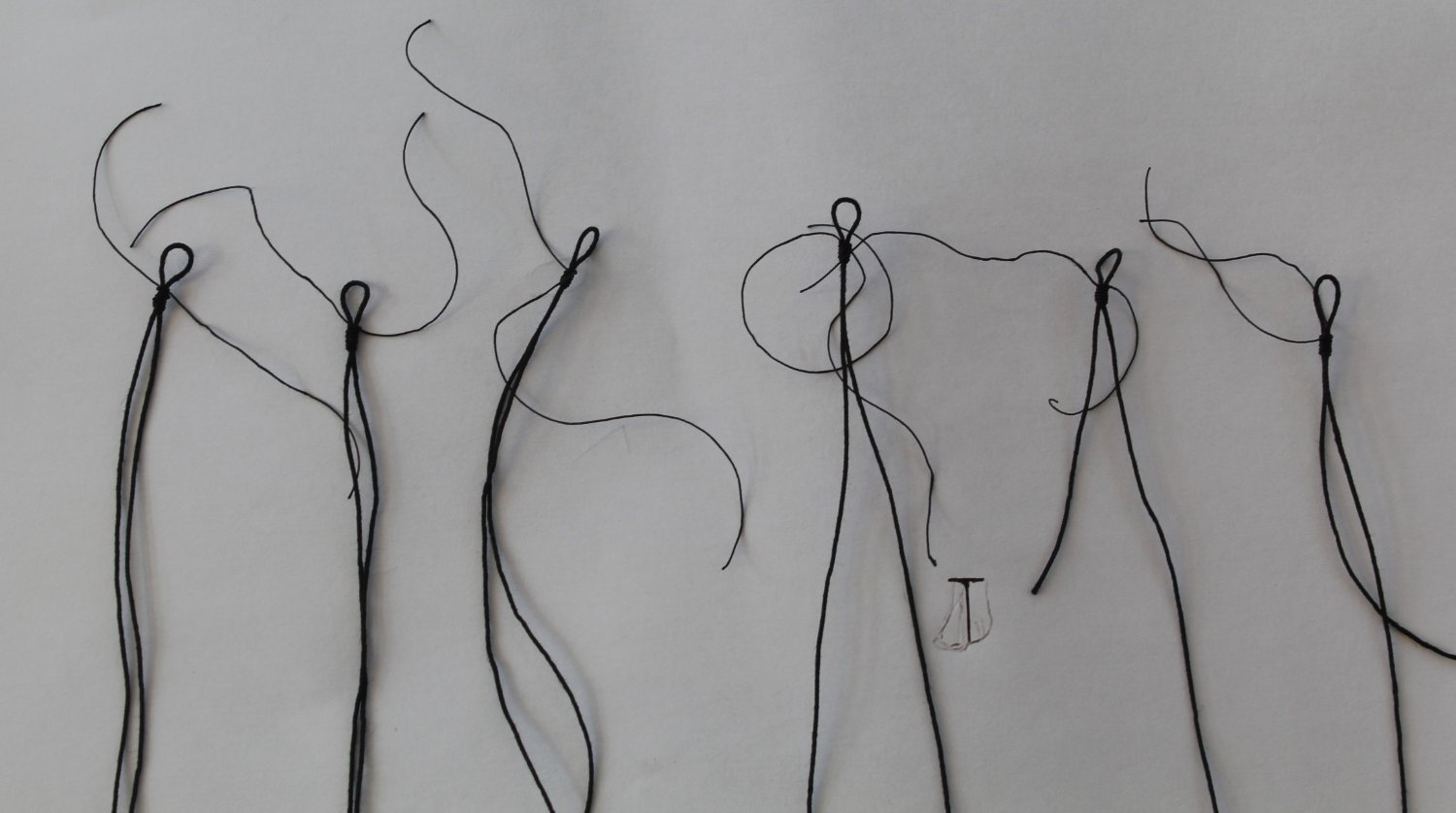
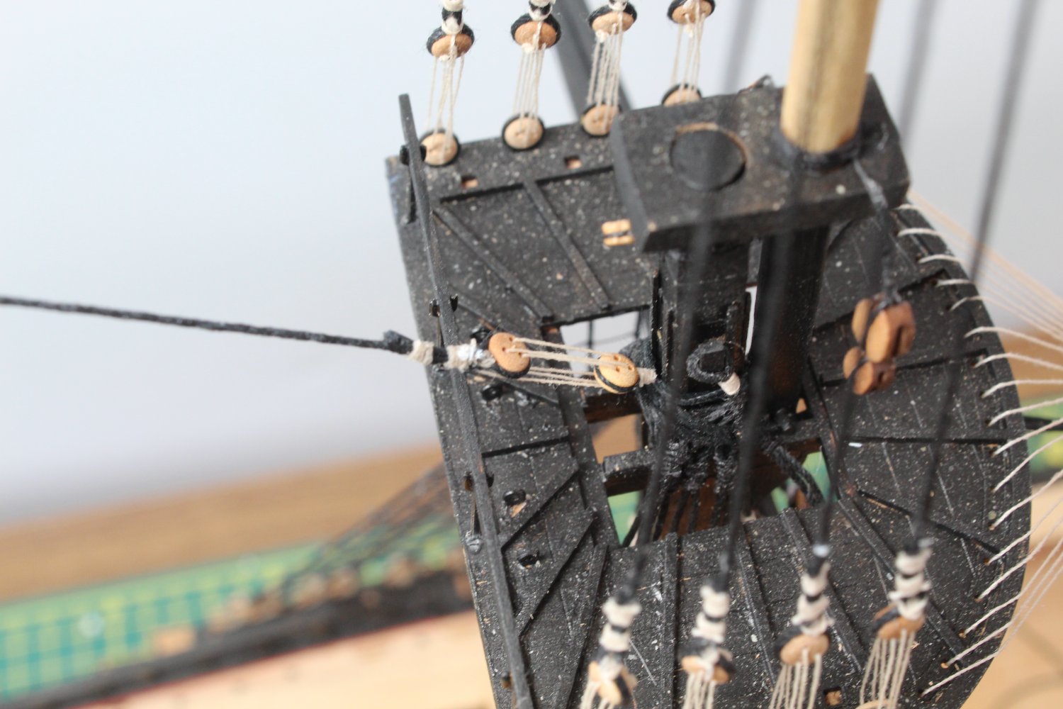
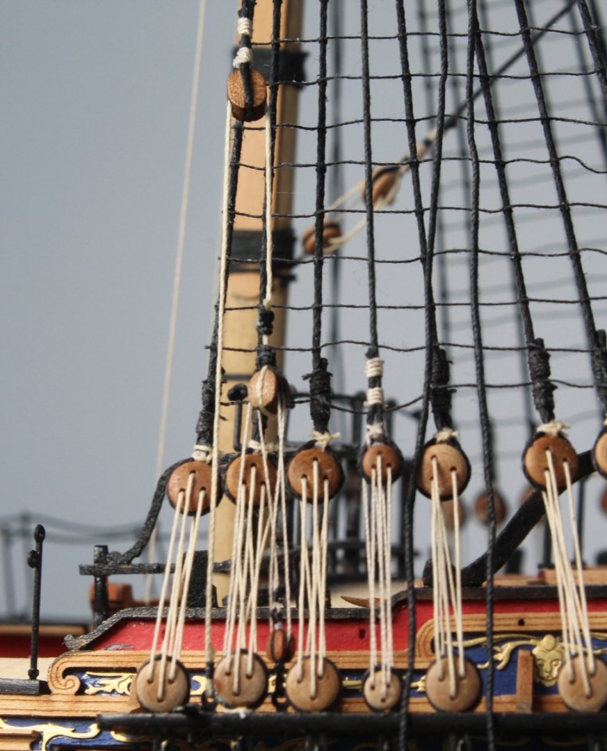
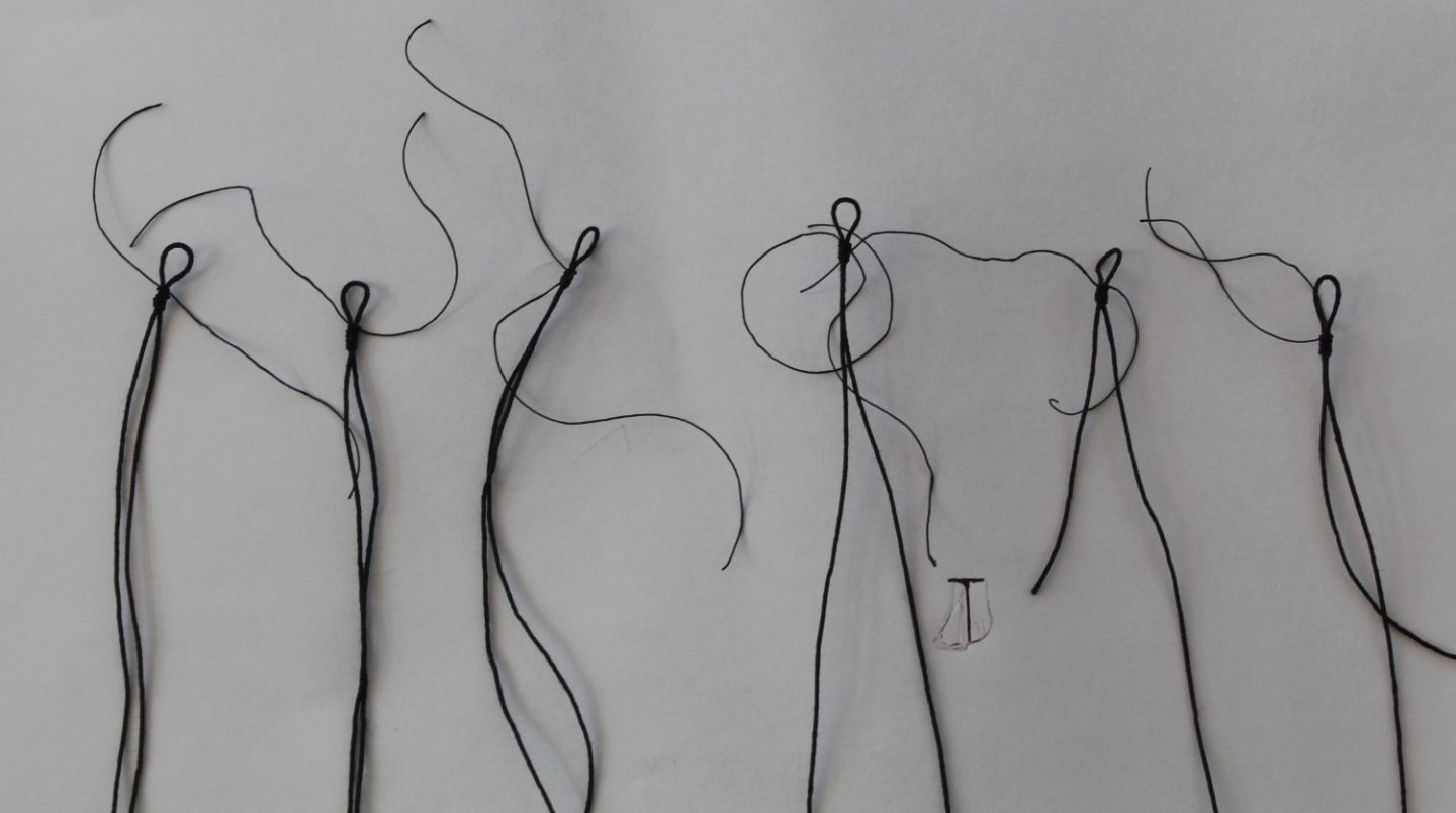
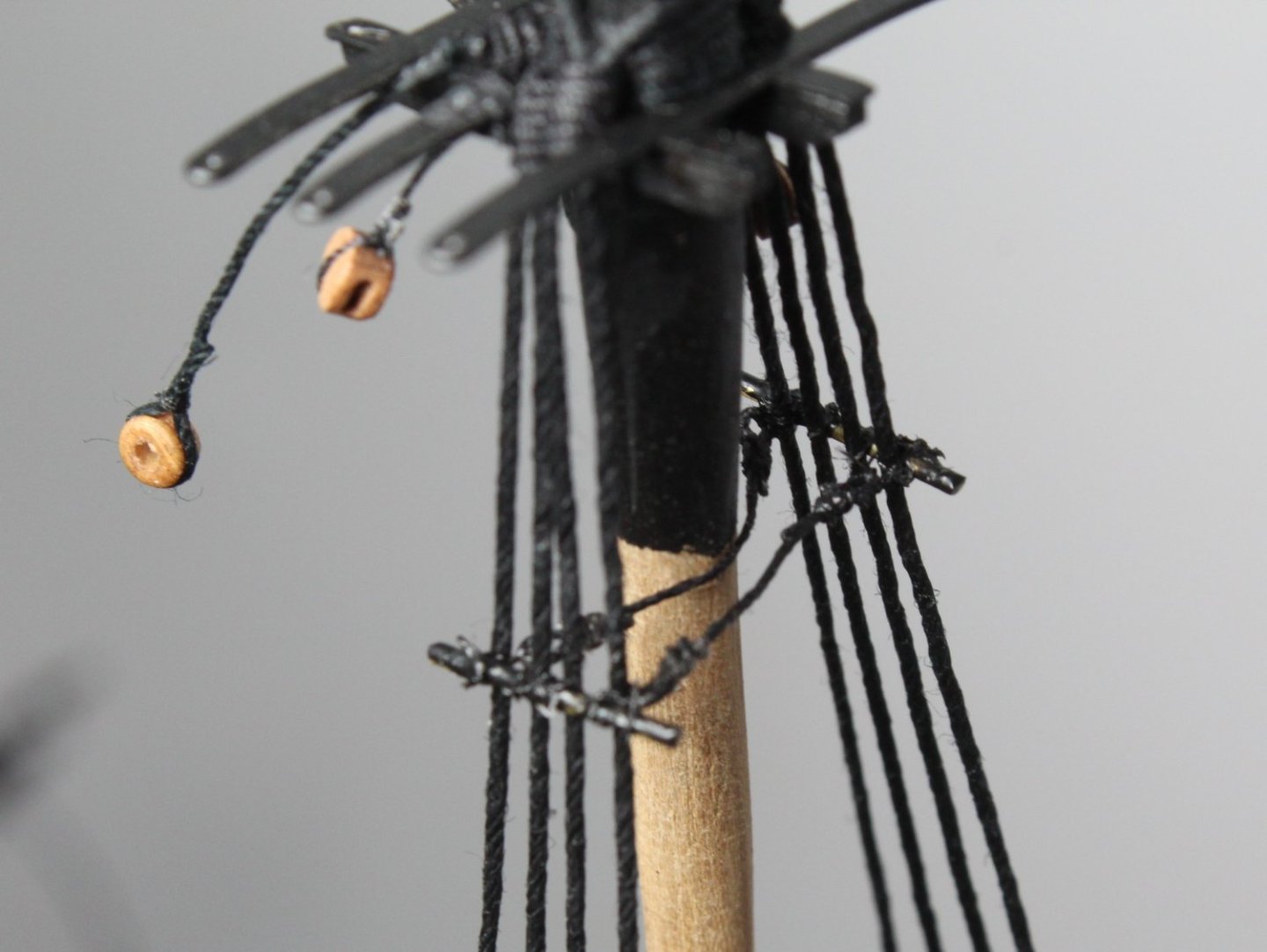
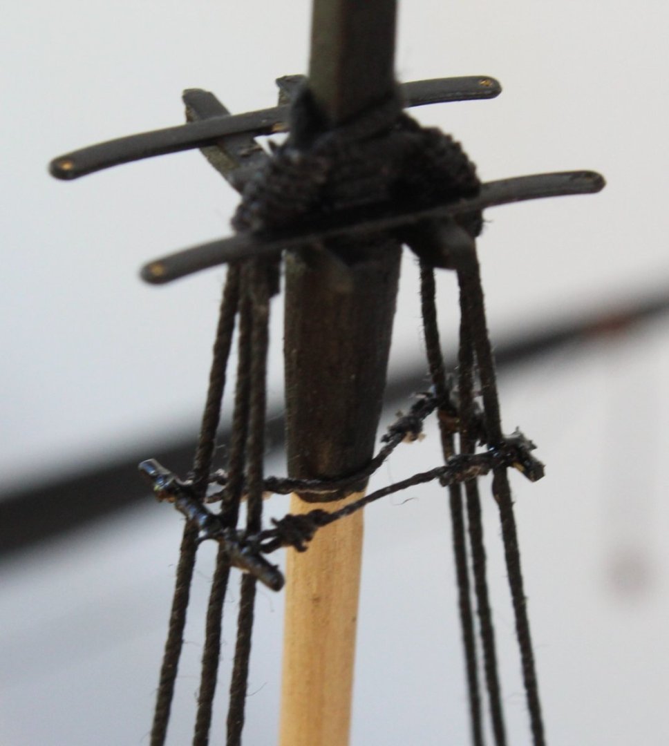
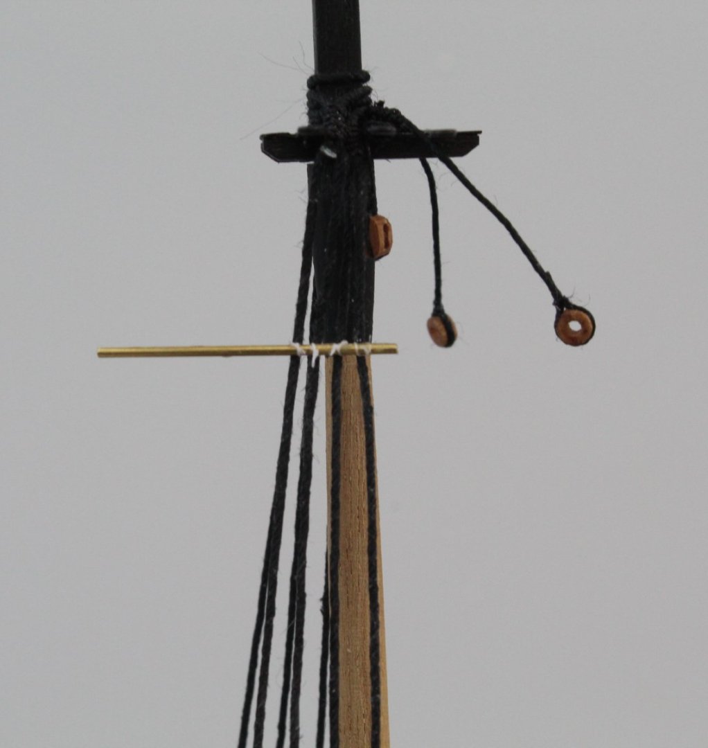
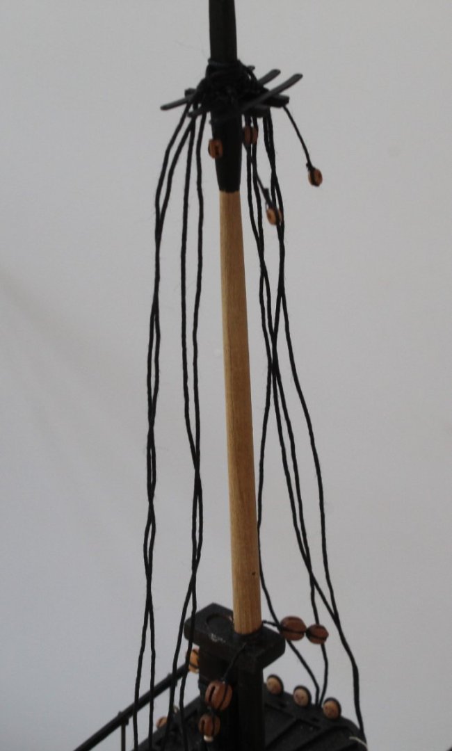
Main Topmast Backstays - Prep Work With reference to the rigging plans there are 5 shroud lines per side for the back stays. As can be seen in the attached photo some of the shroud lines have a block arrangement and some require deadeyes and lanyards. The different block arrangements for the backstays are shown in the next two photos. To start the process I cut 6 of lengths of 0.75mm black. 4 of these lengths will be configured shroud line pairs and the remaining two shorter lengths will be configured as single shrouds for the lagging backstays. A loop is formed and is then held in the quad hands so I can add the seizing. I have continued to use the alternate half hitch knot method for the seizing, 6 on the bottom and 6 on the top. A completed seizing is shown in the photo below. I always ensure the loop is oversized as it will be adjusted to the required size in situ. It is a fairly quick process to complete adding the loop seizing's for all the shroud lines, as can be seen below. The excess thread will be trimmed once a touch of ca gel has been added to the seizing thread. Each shroud pair placed over the topmast in turn. The loop size is then adjusted be pulling the thread as indicated by the arrows on the next photo. I like to leave the loop a tad on the large size for easy of fitting and for positioning when the blocks and deadeyes are added. The same method for adjusting the loop size can be used for the single shroud line. With all the shroud lines added plus the topmast stay and preventor the topmast is starting to look crowded, as can be seen in the next photo. Please note the bottom stay is not correctly positioned in the photo below as it should be under the leading crosstrees and not the middle one. I will also ensure the shroud are correctly positioned before the blocks and deadeyes are added. The next picture does show the the backstay lines hanging down, ready for the blocks and deadeyes to be added. It also shows the topmast stay and preventor in place. They have been fed through the blocks on the foremast and are ready to be belayed to the bitts.


- 476 replies
-
- 6
-
-
- sphinx
- vanguard models
- (and 1 more)
-
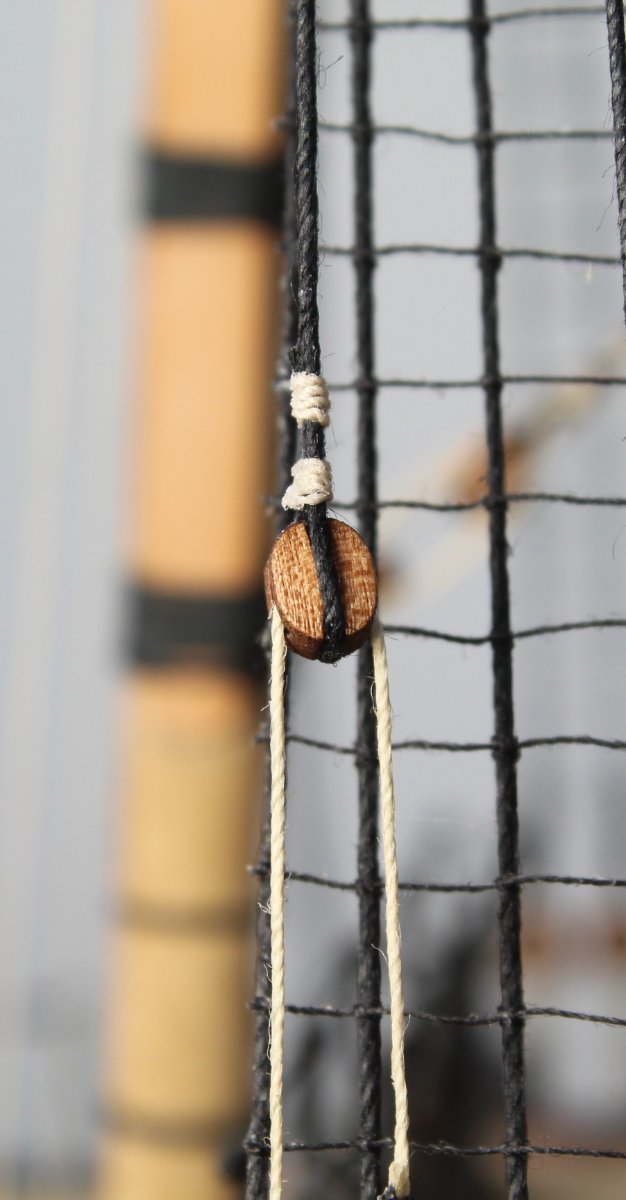
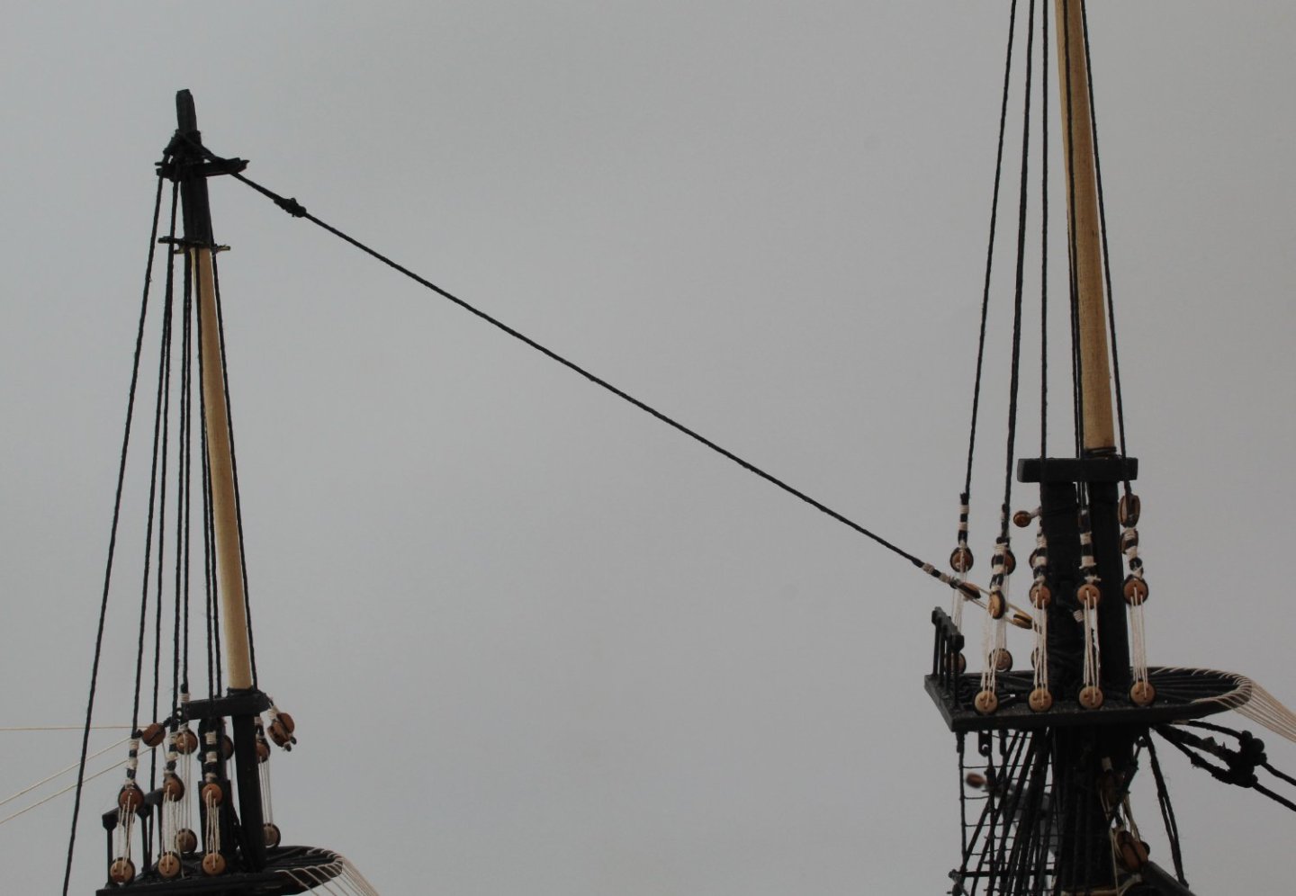
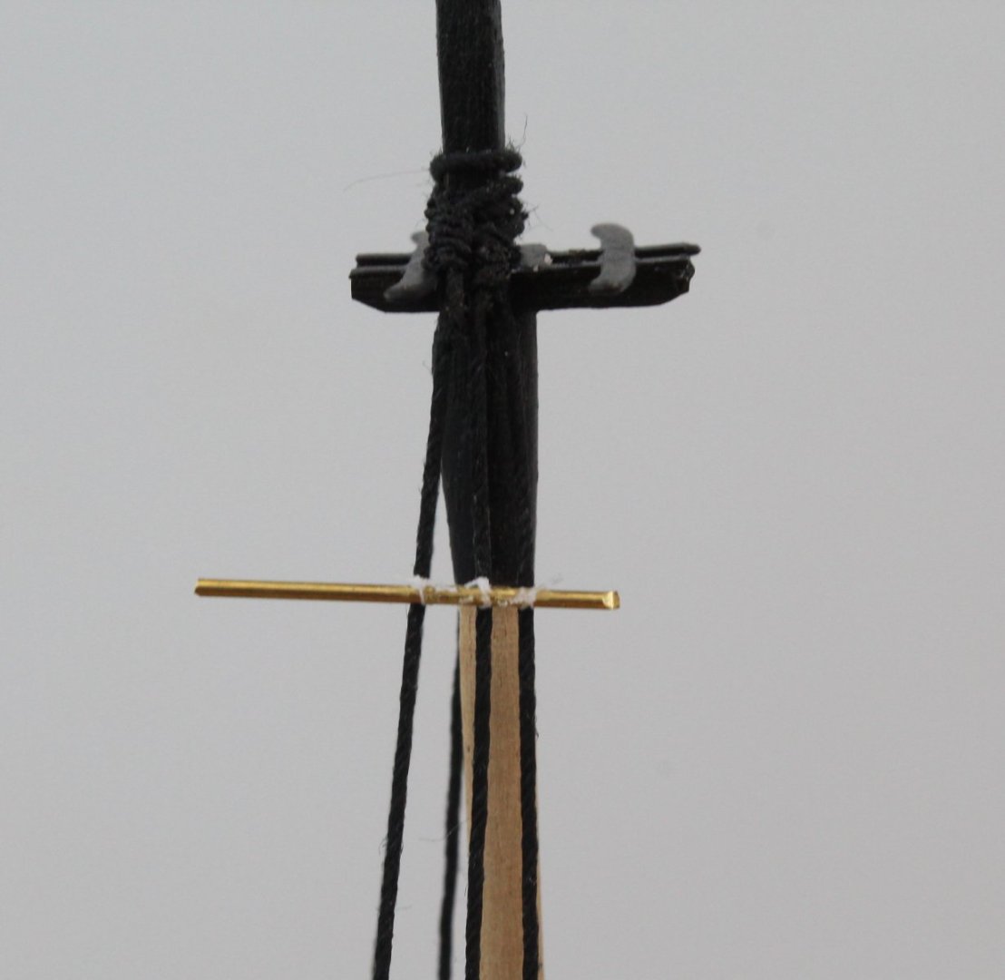
Mizzen Mast Backstay and Topmast Stay Today I have moved on to adding the backstays and topmast stays. I decided to start with the mizzen mast. A 3mm deadeye needs to be added to the hull for the backstay. This is accomplished using a strop to hold the deadeye and a eyebolt to secure to the hull. A length of 0.75mm black thread is required for the backstay shroud line. The completed arrangement with the lanyards is shown in the photo below. The next photo shows the completed backstay. With the mizzen mast backstays in place I moved on to adding the topmast stay. The stay is wrapped around the topmast and secured in place with a mouse, as can be seen in the photo below. The other end of the mizzen topmast stay requires a 3mm deadeye. With the deadeye in place it was a straightforward task to add the lanyards. The next photo shows the entire mizzen topmast mast stay The next photo shows both the mizzen mast backstay and topmast stay in place. Next I will be adding the backstays and stays to the main topmast. In the picture below I have made the topmast stay and preventor and I am currently deciding where I need to place the mouse. These will be removed as the main mast backstays needs to be installed before the stay and preventor can be secured in place.


- 476 replies
-
- 6
-
-
- sphinx
- vanguard models
- (and 1 more)
-
Hello Tim Many thanks for you very kind comments. I like to show the detail and describe the methods of my work as I hope it can help others. I am always looking at other build logs to see how various tasks can be tackled. I still class myself as a novice modeller but I am constantly striving to improve my skills. All the best Glenn
- 476 replies
-
- 2
-
-
- sphinx
- vanguard models
- (and 1 more)
-
Nice work, I still have the task of building the small boats to look forward (dread) to. Glenn
- 857 replies
-
- 4
-
-
- Sphinx
- Vanguard Models
- (and 1 more)
-
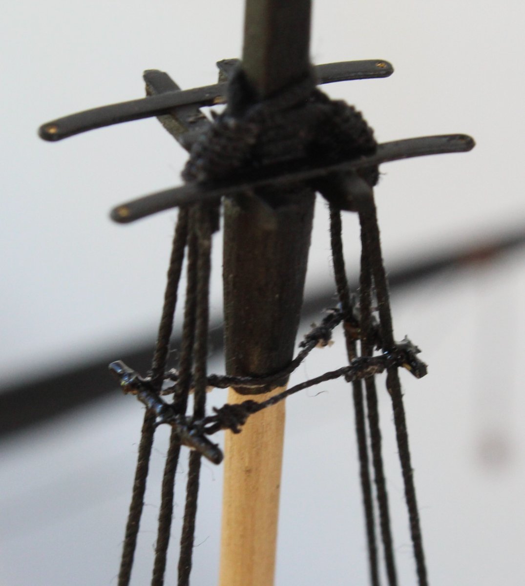
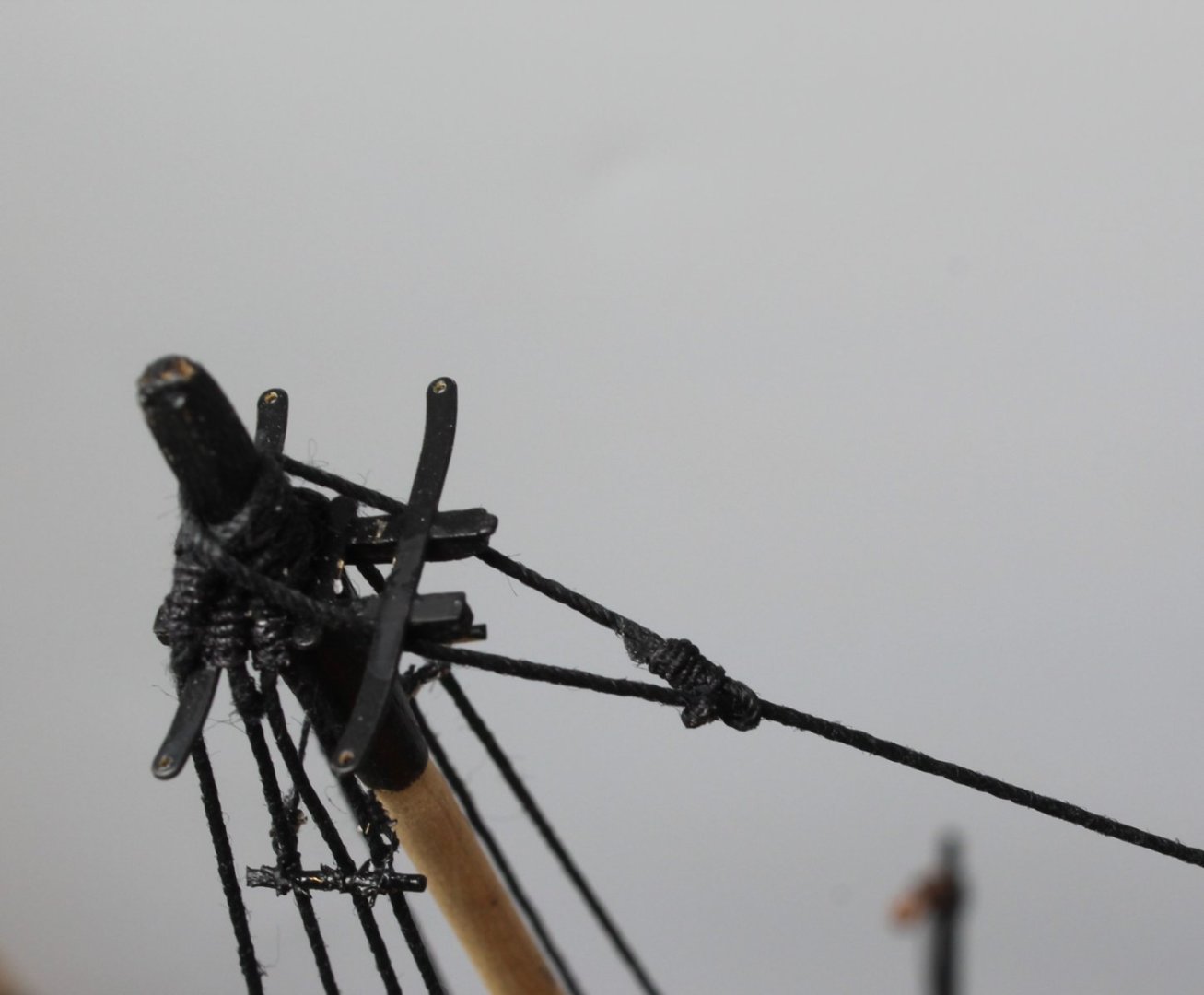
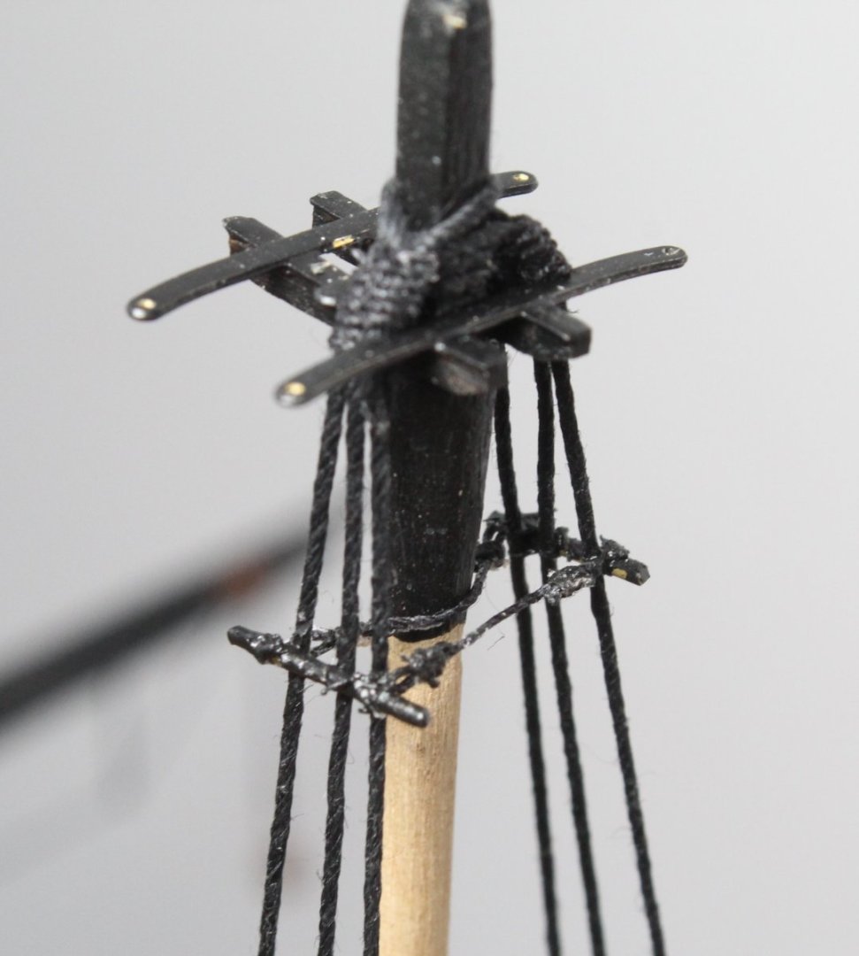
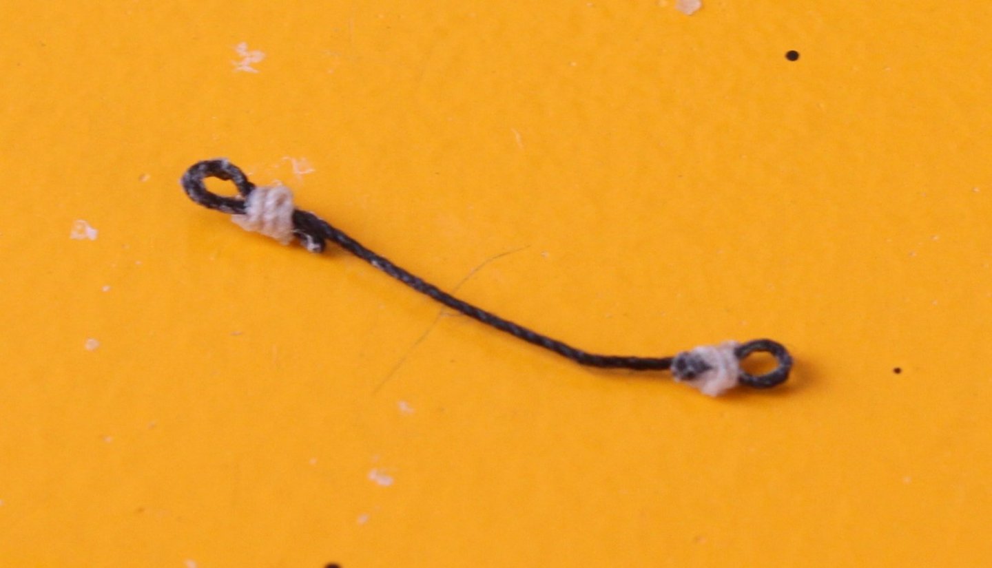
Topmast Catharpins Completed Thankfully the topmast catharpins are now in place. This is, in my opinion, one of the more onerous rigging tasks. That said I have found that the method I have now adopted has yielded a much better end result. Each catharpin is simply a length of thread with thimble eyelets at each end. It can take a bit of trial and error to work out the required overall length of each catharpin. The use of the top and bottom half hitch method when creating the thimbles does allow the seizing position and thimble eyelet size to be adjusted as necessary. I use fly tying thread to secure the staves secured to the shrouds and to also secure the catharpins to the staves. It is not the easiest thread to work with due to it's size but I think it does produce a much better end result. The fore topmast catharpins are shown in the photo below. It will require a little bit more touching up. Next time I will blacking the stave before fitting. The main topmast catharpins are shown in the photo below The mizzen topmast catharpins are shown in the photo below The next picture shows the current build state of the Sphinx I am now moving on to adding the topmast stays which I want to complete before installing the topgallant masts and associated shroud lines. In the picture below I am adjusting the position of the stay so I can determine where I should place the mouse for the fore topmast stay. Sorry for the dirty fingernail I should have cleaned and trimmed it before taking the photo.


- 476 replies
-
- 7
-
-
- sphinx
- vanguard models
- (and 1 more)
-
Mizzen Topmast Catharpins I have completed the work for the mizzen topmast futtock staves and catharpins. I really do not like doing the futtock staves and catharpins, but there are a necessary evil and it is only a few days work. With the futtock staves in place I work out the required length of the catharpins and using the required thread add a thimble to each end. I usually end up making a few threads so I can select the best fit. The next task is to add the catharpin to the futtock stave. I use fly tying thread to secure the catharpin to the futtock stave. This is the part I really detest as the flying tying thread is really thin and it is very difficult to see what I am doing. Testing my patience to the limit the first side of the catharpin is in place. It is now a matter of repeating the process and after a few frustrating hours work the task is complete. One mast complete two more left to do, such fun!!!!!!!

- 476 replies
-
- 2
-
-
- sphinx
- vanguard models
- (and 1 more)
-
Topmast Futtock Staves Adding the Futtock Staves is one of my least favorite tasks, the only task I think I detest more is adding catharpins which will be my next job. Initially the quad hands did not seem to a possible tool to aid this task. Thankfully the Sphinx's parts box came to the rescue, as can be seen in the next photo which shows the arrangement I used to hold the brass rods in place as I added the seizing. For the seizing I am using fly tying thread. The next photo shows all the futtock staves in place. I will trim the staves to the required length once I have installed the catharpins. The next photo shows a close up of the main topmast futtock stave. The futtock stave and thread will be painted black. The next photo shows a close up of the fore topmast futtock stave. The next photo shows a close up of the mizzen topmast futtock stave.

- 476 replies
-
- 3
-
-
- sphinx
- vanguard models
- (and 1 more)
-
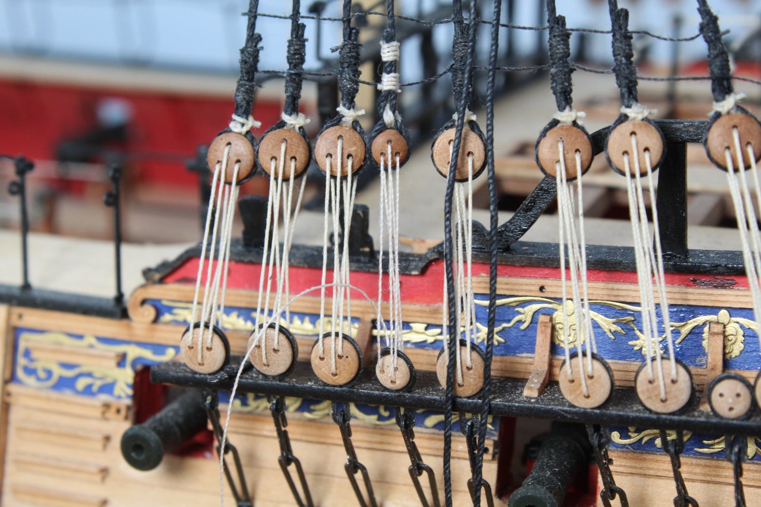
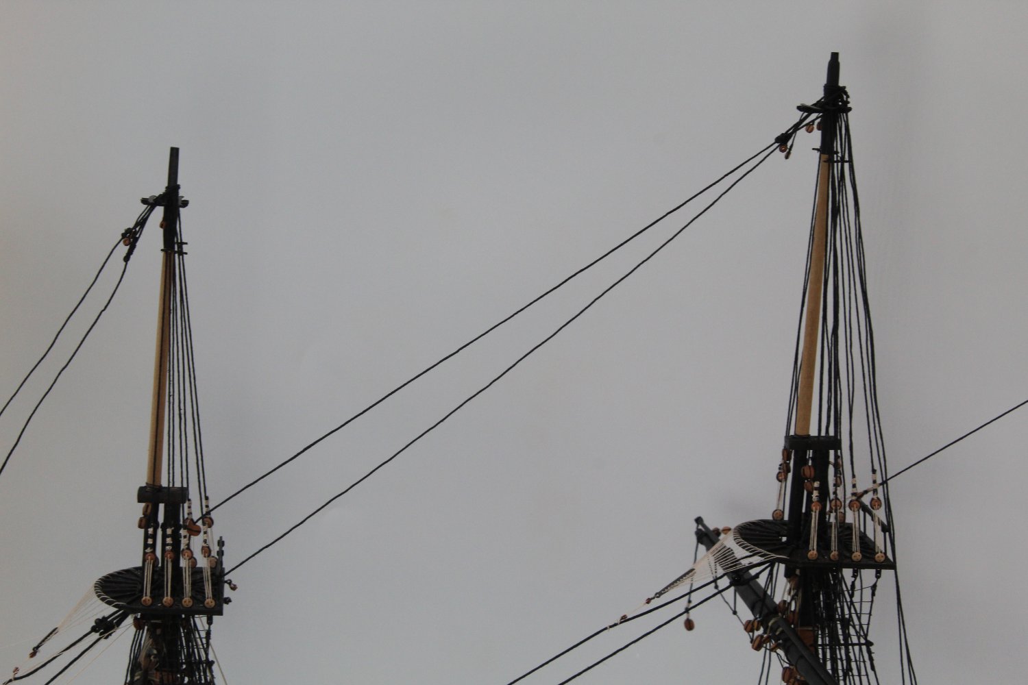
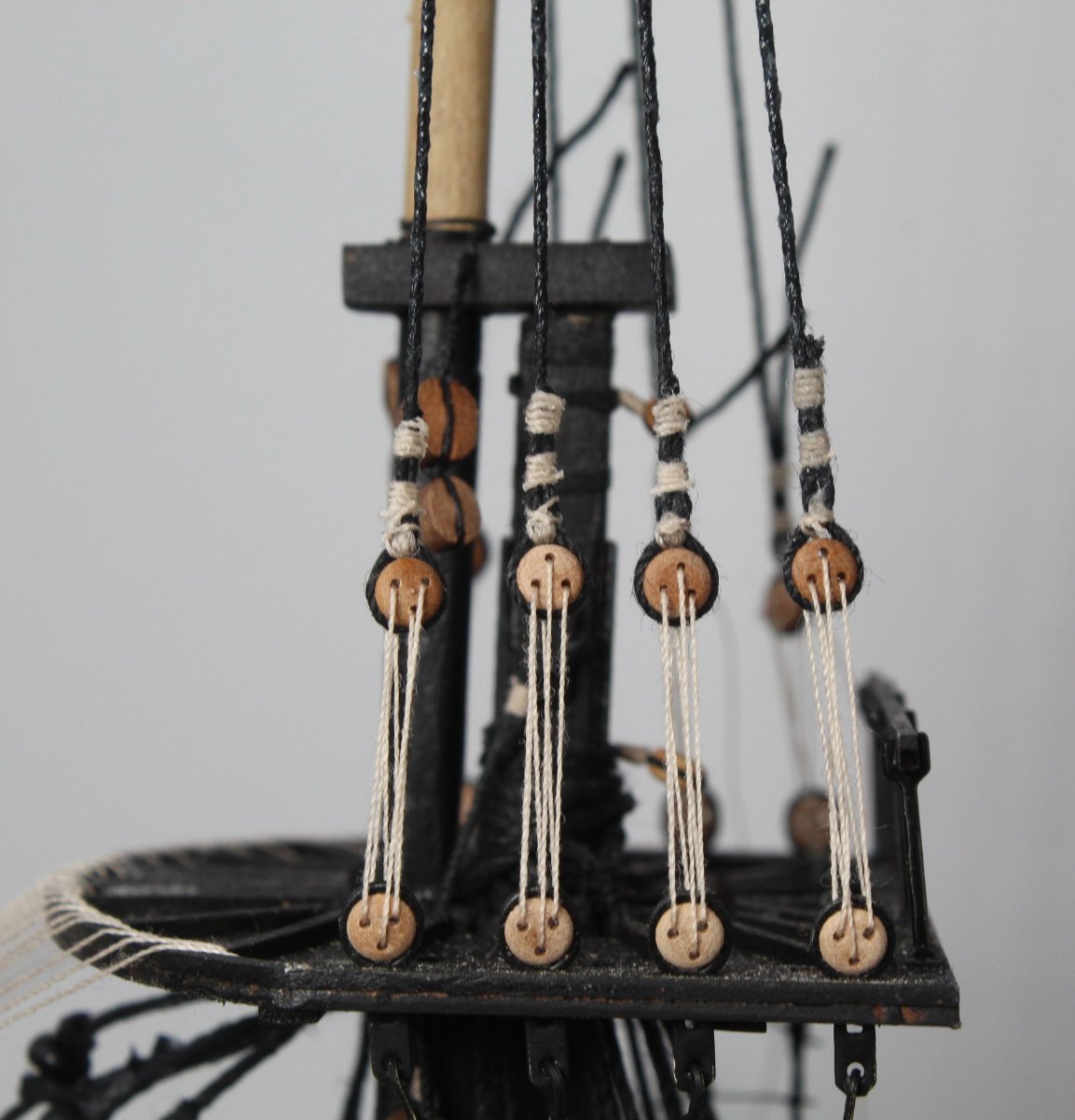
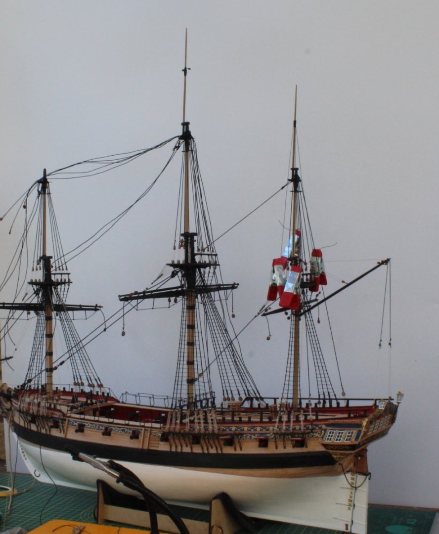
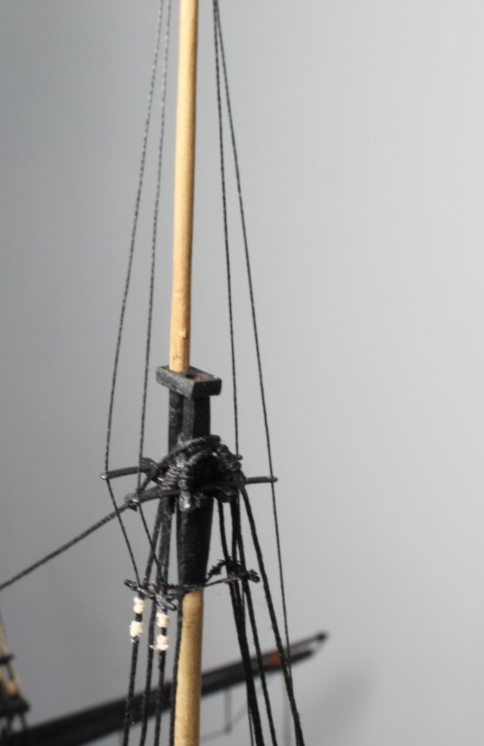
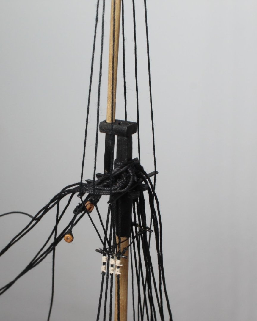
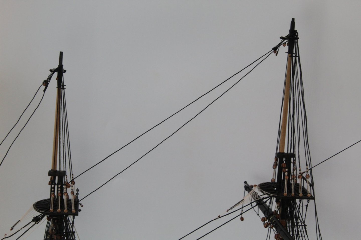
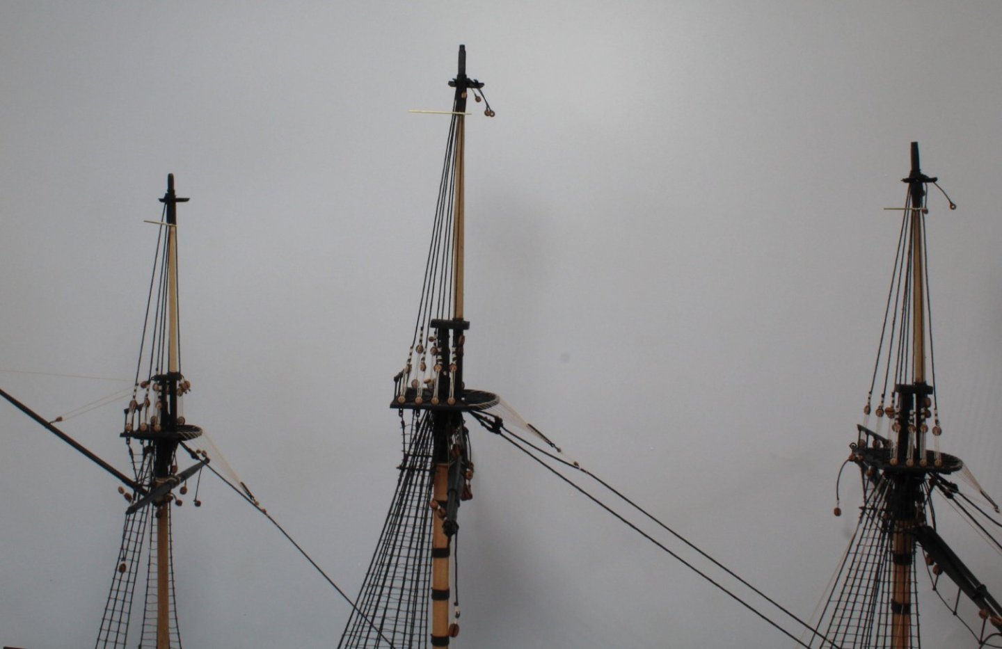
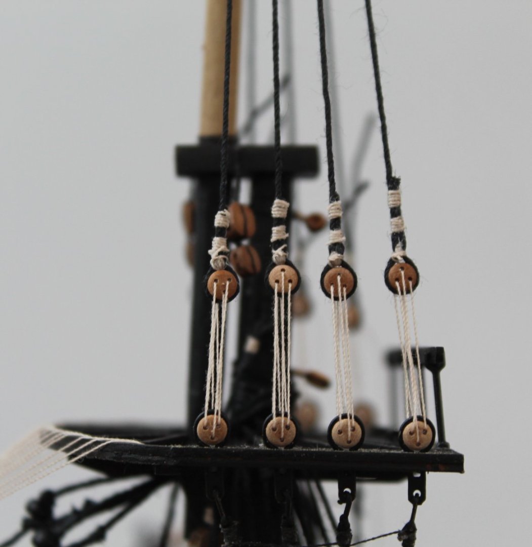
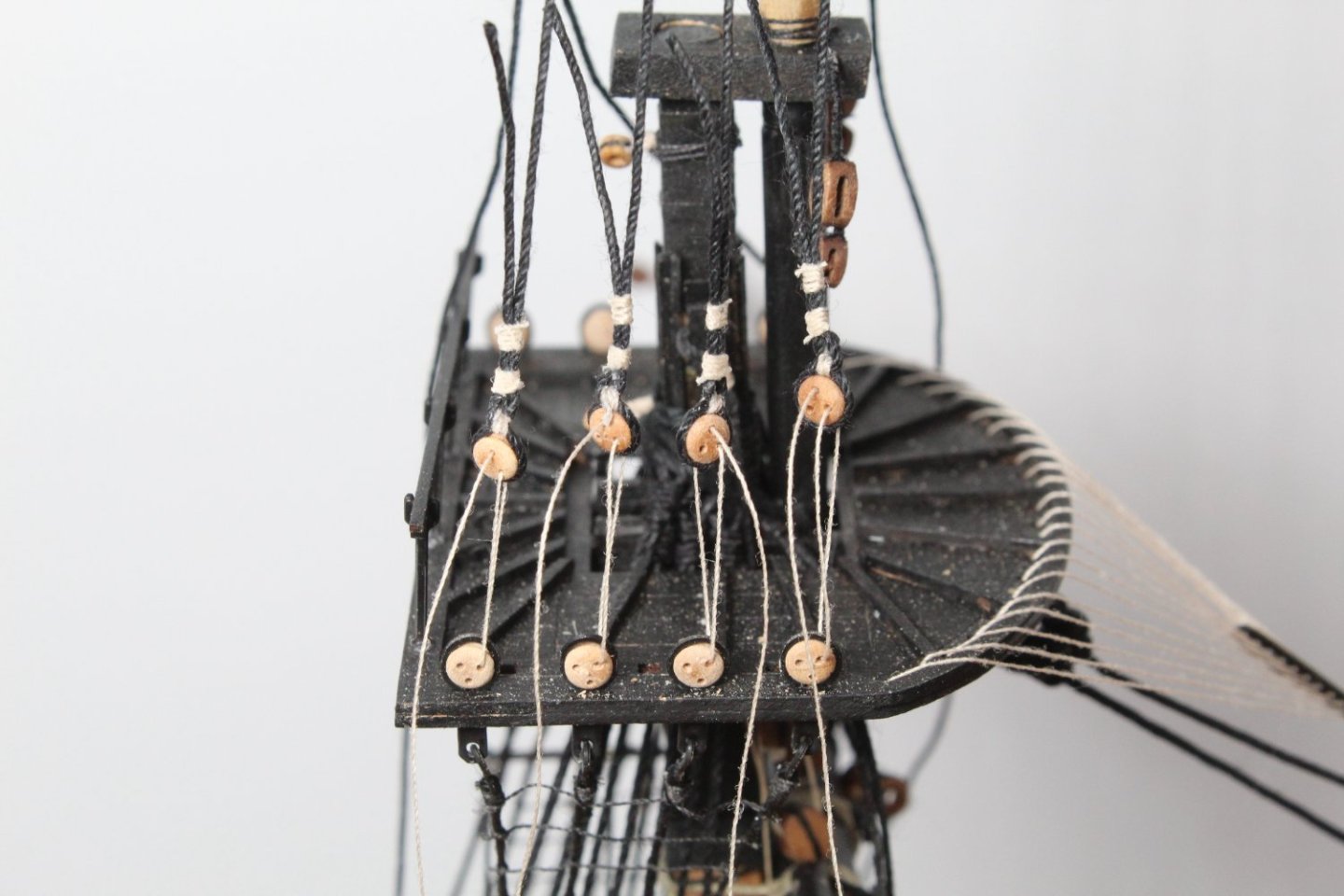
Topmast Shrouds All the topmast shrouds have been fitted and their associated lanyards rigged. For me this is a major milestone completed in the build process, I really like how the Sphinx now looks as can be seen in the next two photos. I tried really hard to get the deadeyes to look even. I did redo a few deadeyes when I was not happy with how they looked once the lanyards had been added. They are still not perfect but they as good as I can get them at the moment, and are so much better than my previous builds. Next up will be to fit the futtock staves followed by the catharpins and ratlines. There's still quite a few more weeks work left before the build is complete. My next project, after the Sphinx, will probably be the Erycina.

- 476 replies
-
- 12
-
-
- sphinx
- vanguard models
- (and 1 more)
-
Hello Bjorn I do like to find out the purpose of the different rigging elements. I also find it very beneficial to plan ahead and to check the rigging paths shown on the plans. I have only downloaded the pdf build manual from Vanguard's web site. I do not have a pdf copy of the plan sheets, sorry for the confusion. All the best Glenn
- 476 replies
-
- 2
-
-
- sphinx
- vanguard models
- (and 1 more)
-
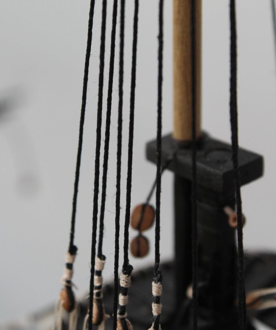
Main Topmast Shrouds I have been away for a few days enjoying the delights of Derbyshire with the family. One of our favourite places to visit in this area of the UK is Chatsworth House. For our American friends Chatsworth is the home of the Duke of Devonshire (Cavendish family). Kathleen (Kick) Kennedy (sister of JFK) married into the Cavendish family and she is buried in the local church cemetery along with all the generations of Dukes of Devonshire family. On my return to the shipyard I started work on adding the shrouds for the main topmast. In the first photo all the shroud lines have been attached to the main topmast and are now ready for the deadeyes. I am using my trusty jig to set the distance between the deadeyes. The first shroud deadeye has been seized in the photo below and seems to be set to the correct spacing. I have started thread the starboard side lanyards. Fingers crossed when the lanyards are tensioned the 4 top deadeyes will be at a similar level. I will add the deadeyes to the port side shrouds before I start to tension all the lanyards.


- 476 replies
-
- 7
-
-
- sphinx
- vanguard models
- (and 1 more)
-
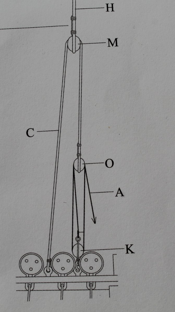
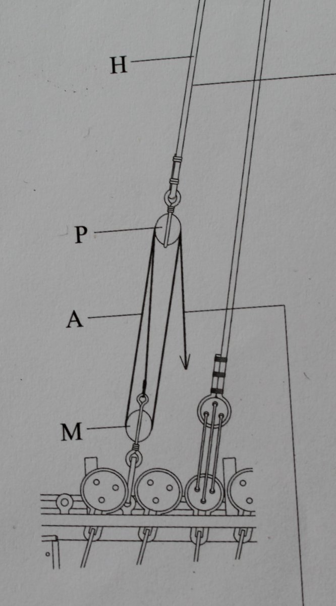
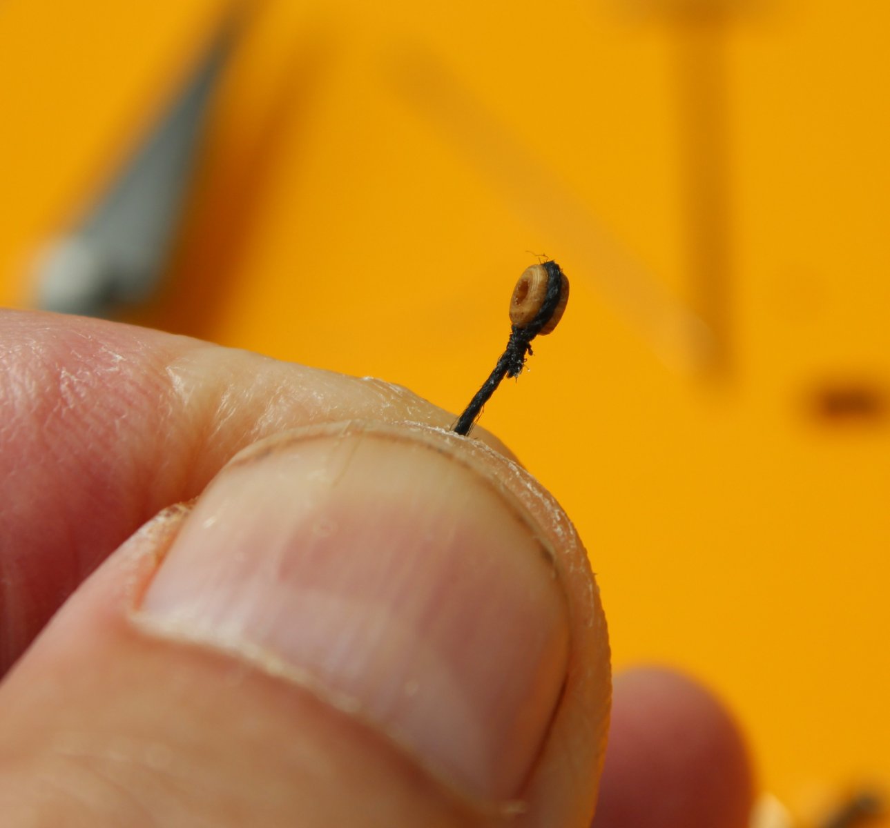
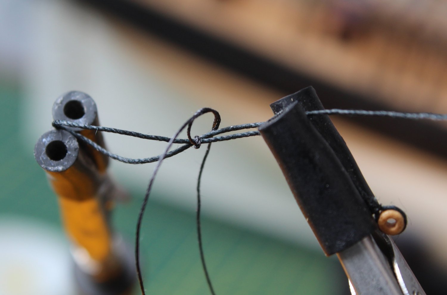
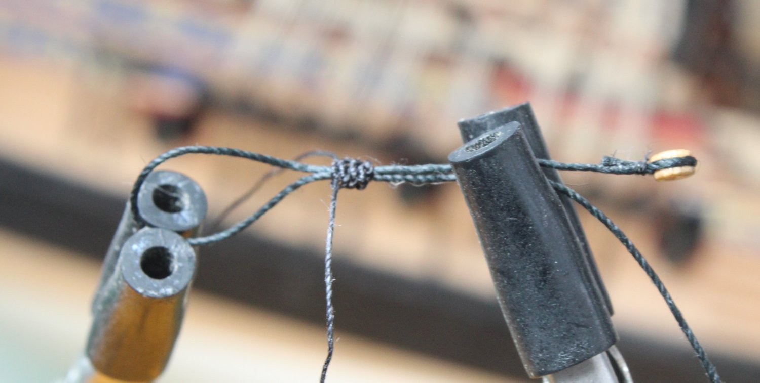
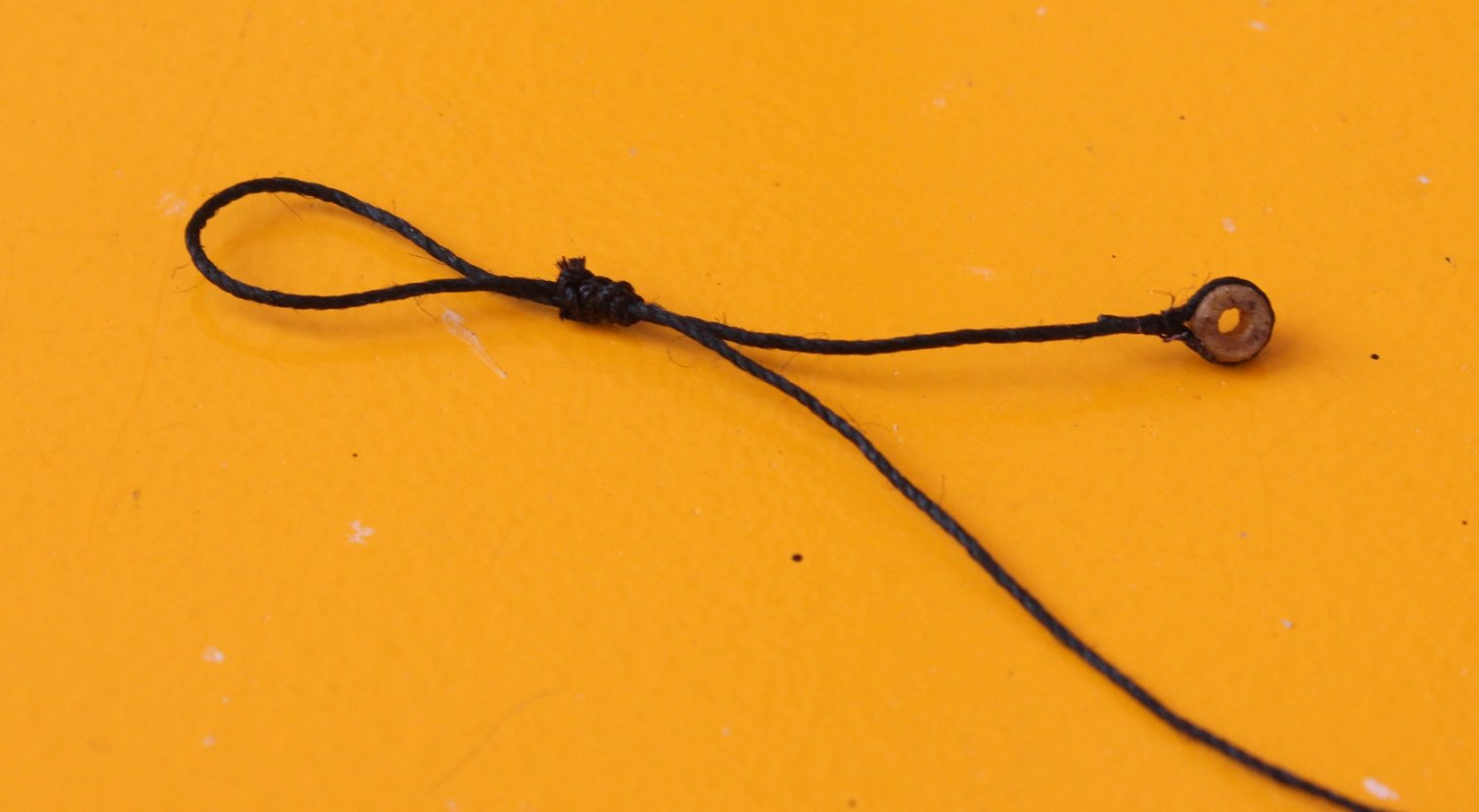
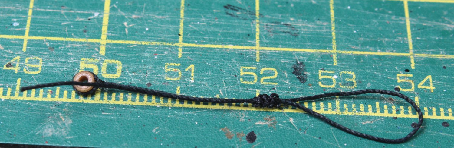
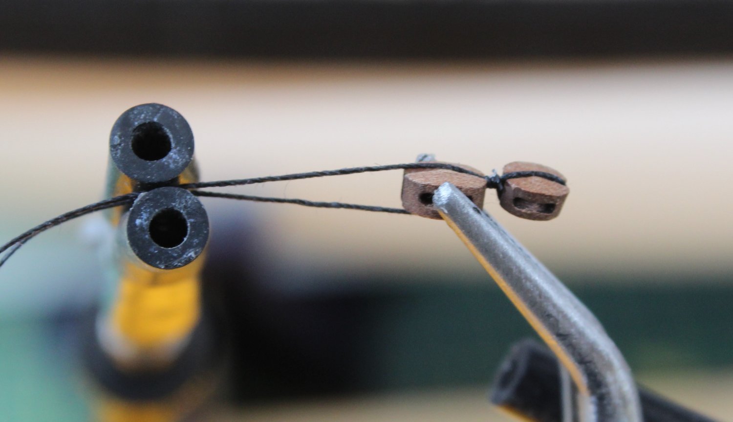
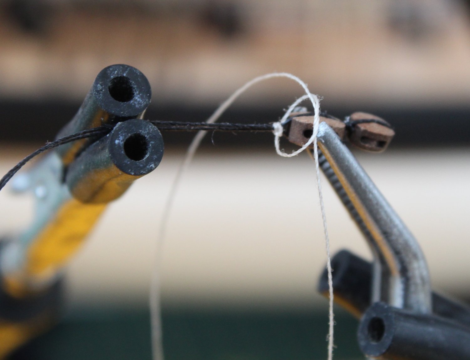
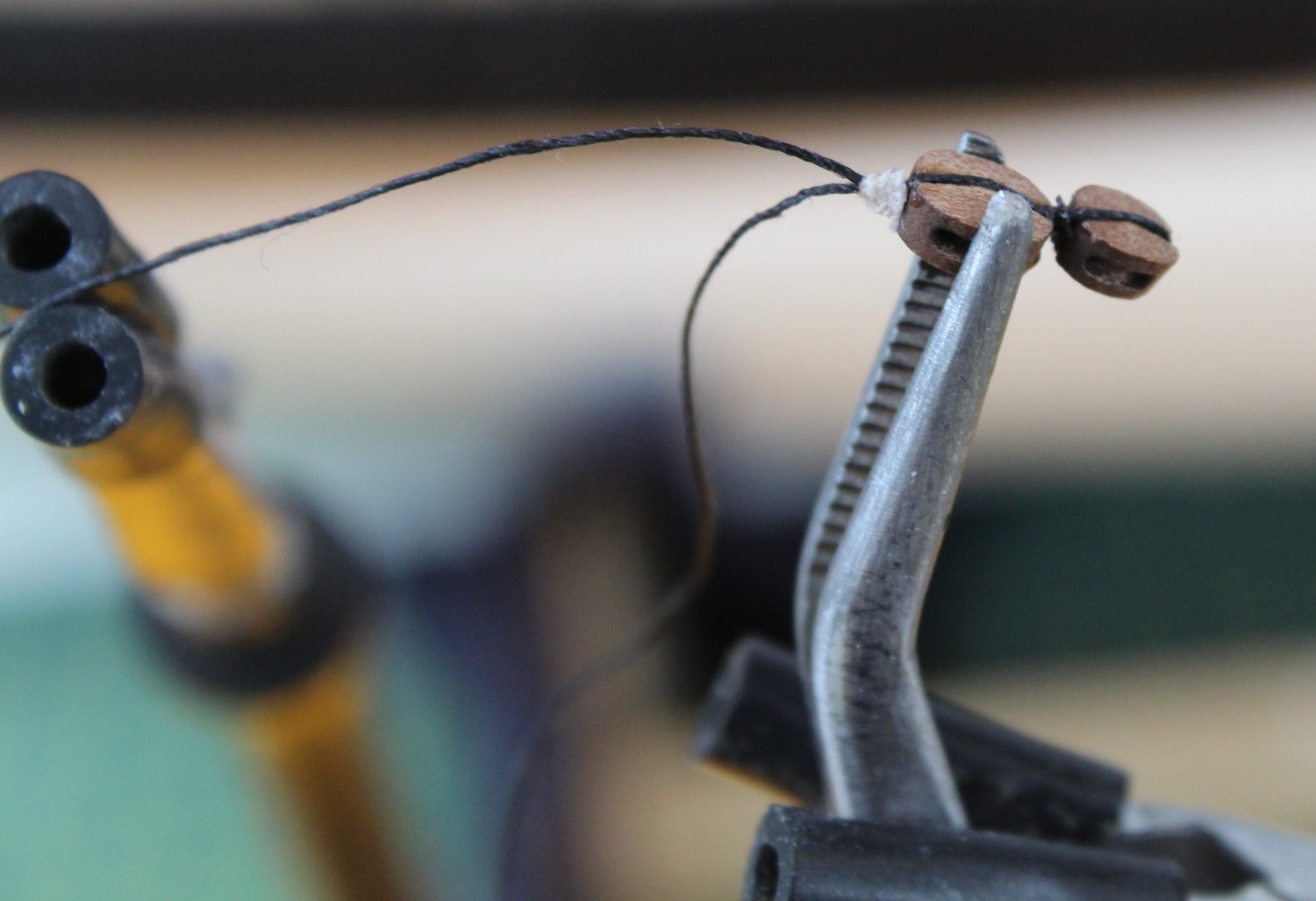
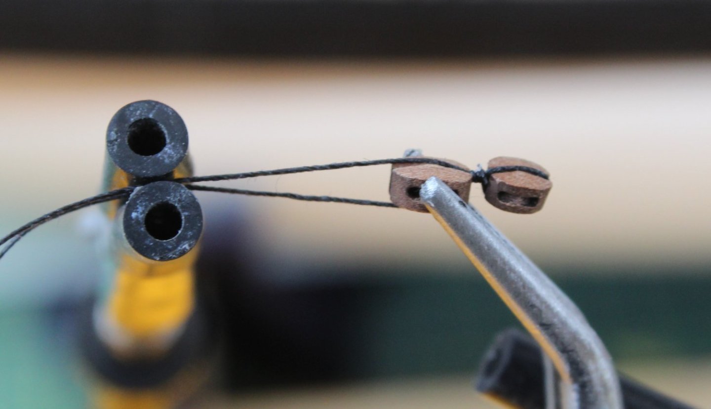
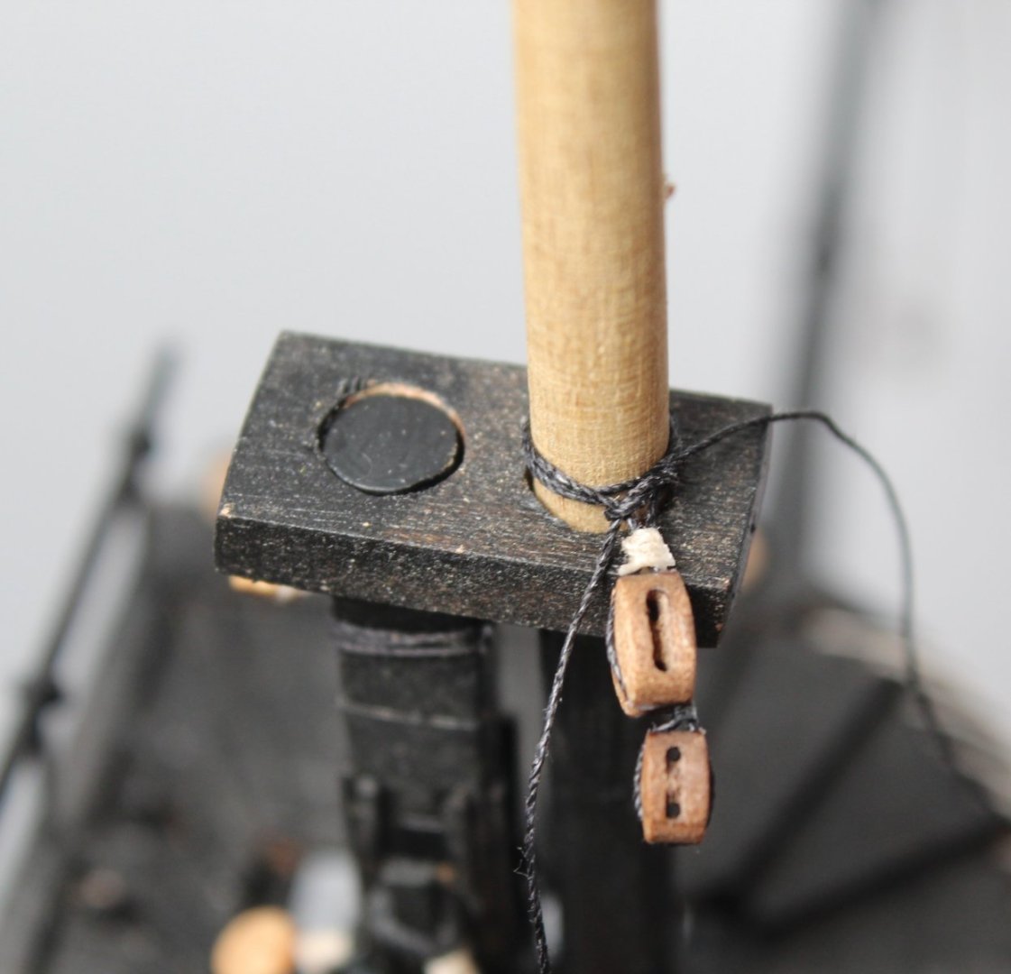
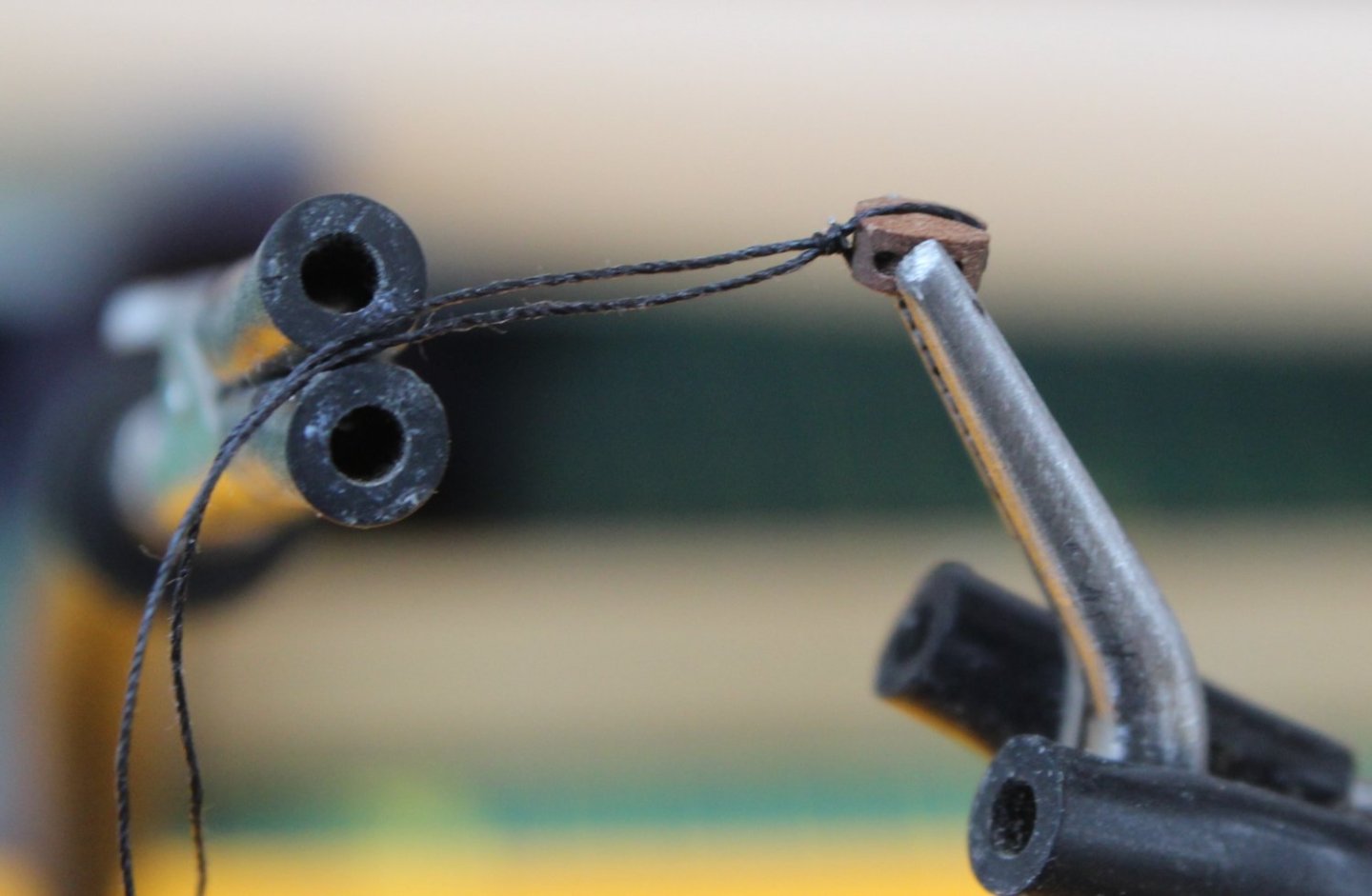
Topmast Burton Pendants Today I have detailed the method I use to make and fit the burton pendants for both the main and fore topmasts. Each of these pendants comprise a 2.5mm block thimble seized to a length of 0.5mm black thread. When I started to rig the Duchess of Kingston I tried to make a serving machine but I decided it was not fit for purpose. Thankfully the time and effort was not wasted as it became a seizing thread dispenser which is shown in the photo below. It currently houses reels of black and white flying tying thread and a reel of 0.1mm natural thread. The photo below also shows a dish where the excess thread ends up once removed. The small strip of yellow tape is where I add small drops of ca gel. I then dip a small metal pin in the ca gel to apply to the knots. The metal pins case can be seen just above the reels of seizing thread. To start the build process I wrap a length of 0.5mm black thread around the thimble and then hold it in place with the quad hands. I am not sure how I managed before I bought the quad hands. I then cut a length of black flying tying thread from my seizing dispenser and proceed to add a series of half hitch knots, 4 to the bottom and 4 to the top. The following photo shows this process where I am about to finish adding one of the bottom half hitches Once I have completed I add a touch of ca gel to the seizing and trim the excess seizing thread. However it can seen in the photo below that the seizing is not tight up to the thimble. Please note I had not removed the excess seizing thread when I took the next photo. Therefore to complete the process I simply take the two free end of the thread and pull them in opposite directions which will pull the seizing tight to the thimble as can be seen in the next photo. It is then a simple task to trim the excess thread which completes the work for the thimble end. The other end of the burton pendant thread will require a loop which goes around the topmast. With the loop created I hold it in place with the indispensable quad hands. Using 0.25mm black thread this time I start to add a series of half hitch knots, as can be seen in the following photo. The next photo shows the completed seizing. The excess seizing thread is ready to be trimmed. The burton pendant is shown below, but there is still a bit more work required before the process is completed. From a bit of experimentation I decided the distance between the thimble and the loop seizing should be around 20mm. It is possible to move the thread through the loop seizing to achieve this, as can be seen below. Next the loop is placed over the topmast. I then pull the free end of thread which tightens the loop around the mast, and retains the 20mm distance between the thimble and seizing. I do like to leave a small amount of slack in the loop. The final task is to remove the remaining excess thread and the job is finally completed as can be seen in the final picture of this post.


- 476 replies
-
- 4
-
-
- sphinx
- vanguard models
- (and 1 more)
-
Concluding Post on Fore and Main Yard Lift Blocks Following on from my last two posts I have now completed all the work related to both the main mast and fore mast yard lift block. The completed blocks were attached to their respective masts using a basic clove hitch knot which I have found to be the best way to secure blocks to masts and yards. The following picture shows the main mast yard lifts in place, noting there is hole above the endcap which has been drilled to accept the locating pin on the main topyard. The following picture shows the fore mast yard lifts in place, noting there is hole above the endcap which has been drilled to accept the locating pin on the fore topyard. I should really fill the top of the endcap where the foremast come through. I would need to buy some more wood filler as I have run out. I thought I would conclude this post with a picture of the Sphinx on the work bench where she now waiting for the both the main and fore topmasts burton pendants and shrouds to be added.
- 476 replies
-
- 6
-
-
- sphinx
- vanguard models
- (and 1 more)
-
Following on from my last post I eventually opted to use black fly tying thread for the final seizing. With a bit of experimentation I decided on approx. 1cm of seized thread between the 5mm block and the mast. After a trial fit of the completed yard lift block assembly I am now very happy with the end result. I just need to complete the modifications the other three double block yard lift assemblies, one more for the main mast and two more for the foremast yard lift. It is a bit fiddly and difficult to see when using the very thin black fly tying thread for the seizing over the black thread wrapped around the block. It takes a bit more time and patience to get the job done but it is well worth the extra effort.
- 476 replies
-
- 3
-
-
- sphinx
- vanguard models
- (and 1 more)
-
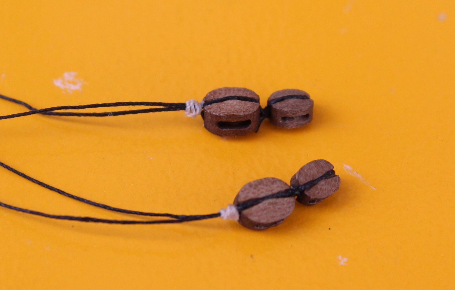
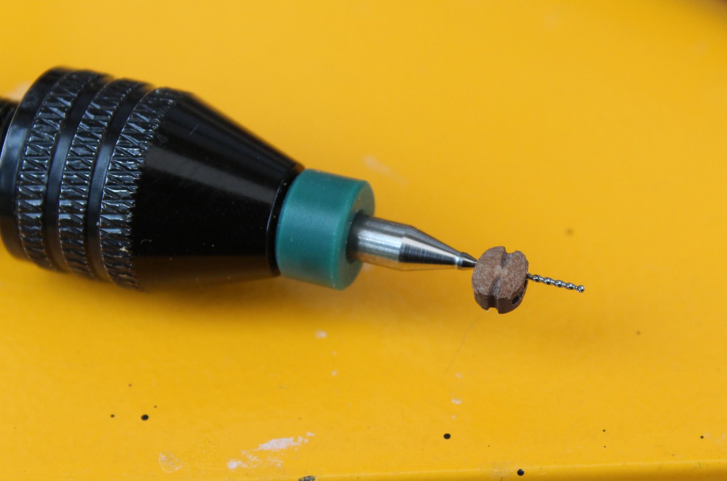
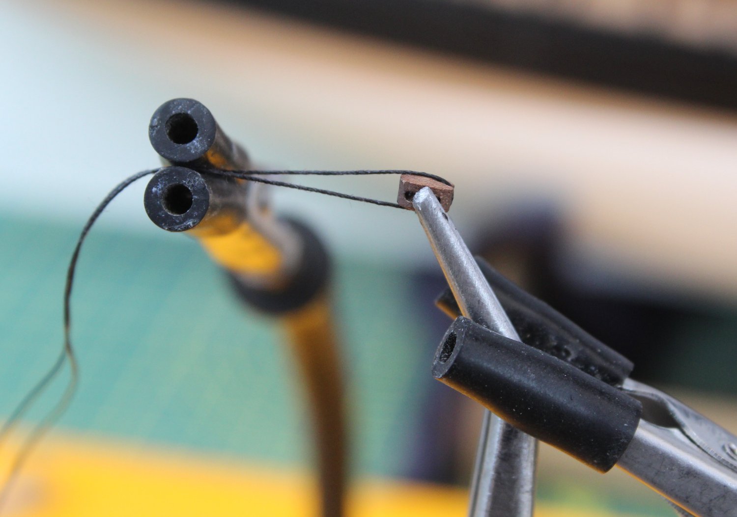
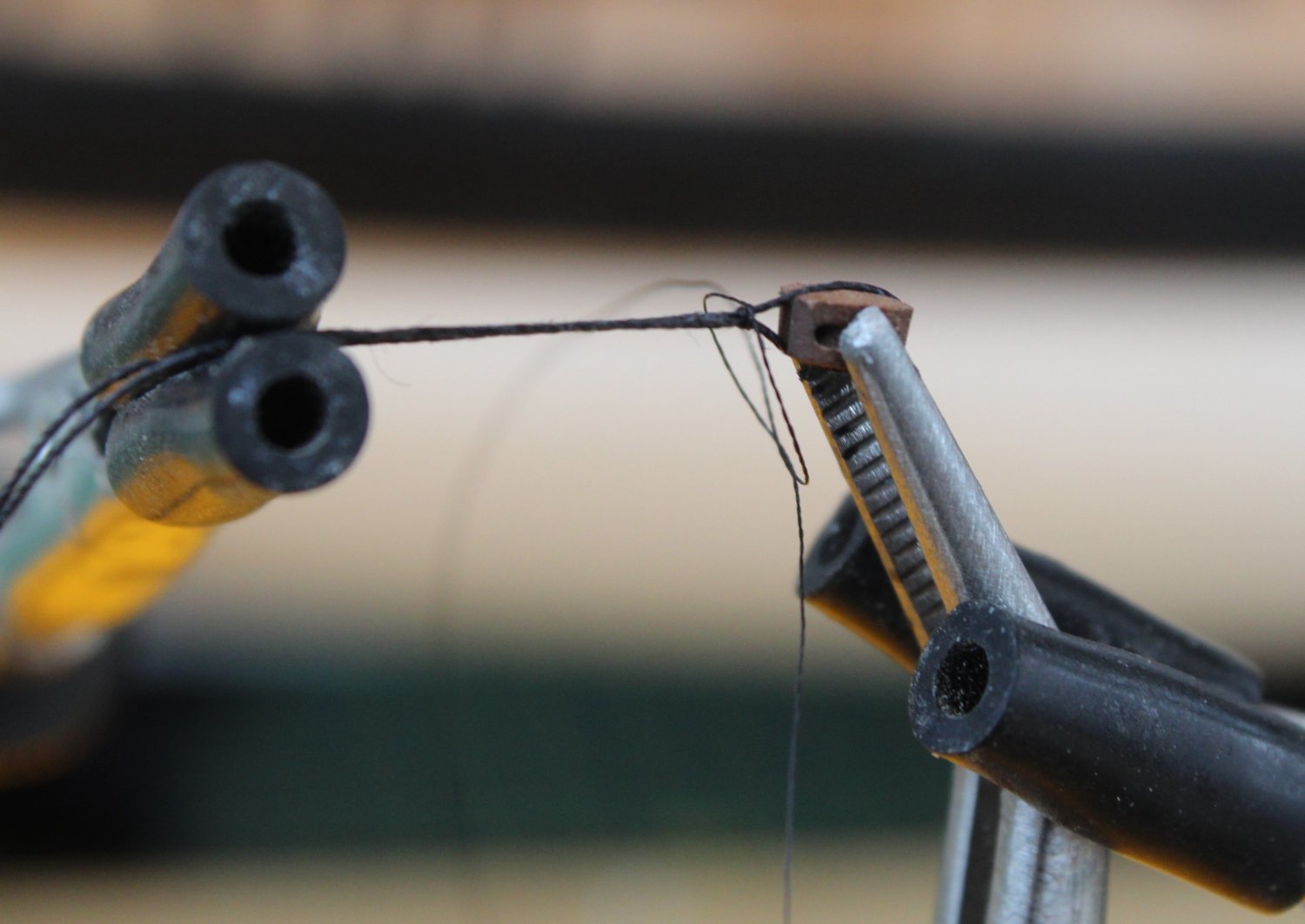
Main Yard Lift Double Block Manufacture I thought I would share the method I have used this morning to make the 2 off main yard lift double block assembly. These block assemblies are both fastened around the main topmast, sited just above the end cap. Each double block assembly comprises a 4mm and a 5mm single block. When checking the rigging plans I noted that 0.25mm natural thread will be used when these blocks are rigged with the double blocks located on each the end of main yard. The first task is to make sure the holes in the blocks will take the required thread therefore I run a suitably sized micro drill through the holes as can be seen in the photo below. Starting with a 4mm block I hold it in place using my quad hands. An approx. 20cm length of 0.25mm black thread is then wrapped around the block and the two free ends of the thread are held in place also with the quad hands. This arrangement is shown is the next photo. I decided to use some black flying tying thread for the seizing. For the seizing I am using a series of half hitch knots. The first one is place on the underside, the second is placed on the top side. In the picture below I am in the process of adding one to the top side. In total I add 4 off half hitch knots to the top and 4 off half hitch knots to the underside. Once the seizing is completed I add a touch of CA gel to the seizing and trim the excess thread. As can be seen in the photo below the seizing is not, as yet, tight up against the block. The seizing can be moved tight to the block by simply pull the two free thread ends in opposite directions. Next a 5mm block is held in the quad hands and the thread, complete with the 4mm block, is wrapped around the block. The free ends are the held in place with the quad hands. This arrangement is shown in the next photo. The 5mm block is then seized. I decided to use some 0.1mm natural thread for this. In the next photo I am in the process of adding the second half hitch knot to the top side. In total I added 4 off half hitch knots to the top and 4 off half hitch knots to the underside. After a touch of ca gel is applied to the seizing the excess thread is trimmed and the two free ends are pulled in opposite directions to ensure the seizing is tight against the 5mm block. After around 45 minutes of effort I have completed both double yard lift blocks for the main mast. The double block arrangement can then be added to the main top mast. I have made a trial fit, as can be seen in the photo below. I need to increase the distance between the 5mm block and the main top mast as it is clearly to close to the end cap. I have three option to solve this: a) Remove the 5mm block seizing and then redo with 0.1mm natural thread with around 10 off top and 10 off bottom half hitch knots. b) Leave the existing seizing in place and add a few more op and bottom half hitch knots, maybe using the fly tying black thread. c) Remove the 5mm block seizing and then redo with black fly tying thread with around 10 off top and 10 off bottom half hitch knots. I will probably try method b) first but I am tempted to revert to method c.


- 476 replies
-
- 7
-
-
- sphinx
- vanguard models
- (and 1 more)
-
Gaff Halliard After completing the mizzen topmast shrouds I decided to complete the Gaff Halliard rigging. This required two lengths (approx. 100mm) of 0.5mm black thread rigged to the end of the mizzen gaff. I then made up two 3mm single blocks with a thimble (eyelet) on each end. The two free ends of the black thread were attached, via the thimble, to their respective blocks. Two lengths of 0.1mm natural thread was then attached to the thimbles at the other end of the blocks. Next I seized to further 2 off 3mm single blocks, adding a rigging hook to one end of each block. The two rigging hooks were fed through the two outer most eyelets on the inner stern fascia panel. It was then a simple case of rigging the 0.1mm natural thread from the upper blocks through the lower blocks and then back up and through the top blocks before being belayed to the outer most cleats on the inner stern fascia panel. Next I will making up and securing the main and fore mast double yard brace block assemblies. Once that is done I plan to add the main and fore top mast shrouds lines

- 476 replies
-
- 6
-
-
- sphinx
- vanguard models
- (and 1 more)
-
I did find the Amati clips a useful tool when I was doing the first planking.
- 426 replies
-
- 2
-
-
- Vanguard Models
- Sphinx
- (and 1 more)
-
Mizzen Top Shrouds - WIP Work has been slow on the Sphinx build over the last few days as the weather has been really nice so I have been spending some time in the garden. We have also spent time looking after our grandchildren which is always fun. I have now added the two crossjack lift blocks to the mizzen top mast, which are shown in the top right hand corner of the picture below. I have also started to add the mizzen topmast shrouds. The starboard side is complete and the lanyards just need tying off. When looking at the following picture I have just noticed that the rear deadeye strop has broken free and is not now flush with the platform. This is a tad frustrating but I am not planning to remove the shroud, reseat the strop and to then redo the shroud line as this may also impact of the futtock shroud rigging. I am also reasonable happy with the alignment of the shroud deadeyes. As can seen in the next picture I only have one shroud left to do on the port side. The final shroud line has been fitted and just need to have the deadeye and lanyards adding.

- 476 replies
-
- 4
-
-
- sphinx
- vanguard models
- (and 1 more)