Glenn-UK
-
Posts
3,175 -
Joined
-
Last visited
Content Type
Profiles
Forums
Gallery
Events
Everything posted by Glenn-UK
-
 It will be the marker for the start of the decals so I think the "Erycina" mystery has now been solved.😀
- 106 replies
-
- 1
-

-
- Erycina
- Plymouth Trawler
- (and 3 more)
-
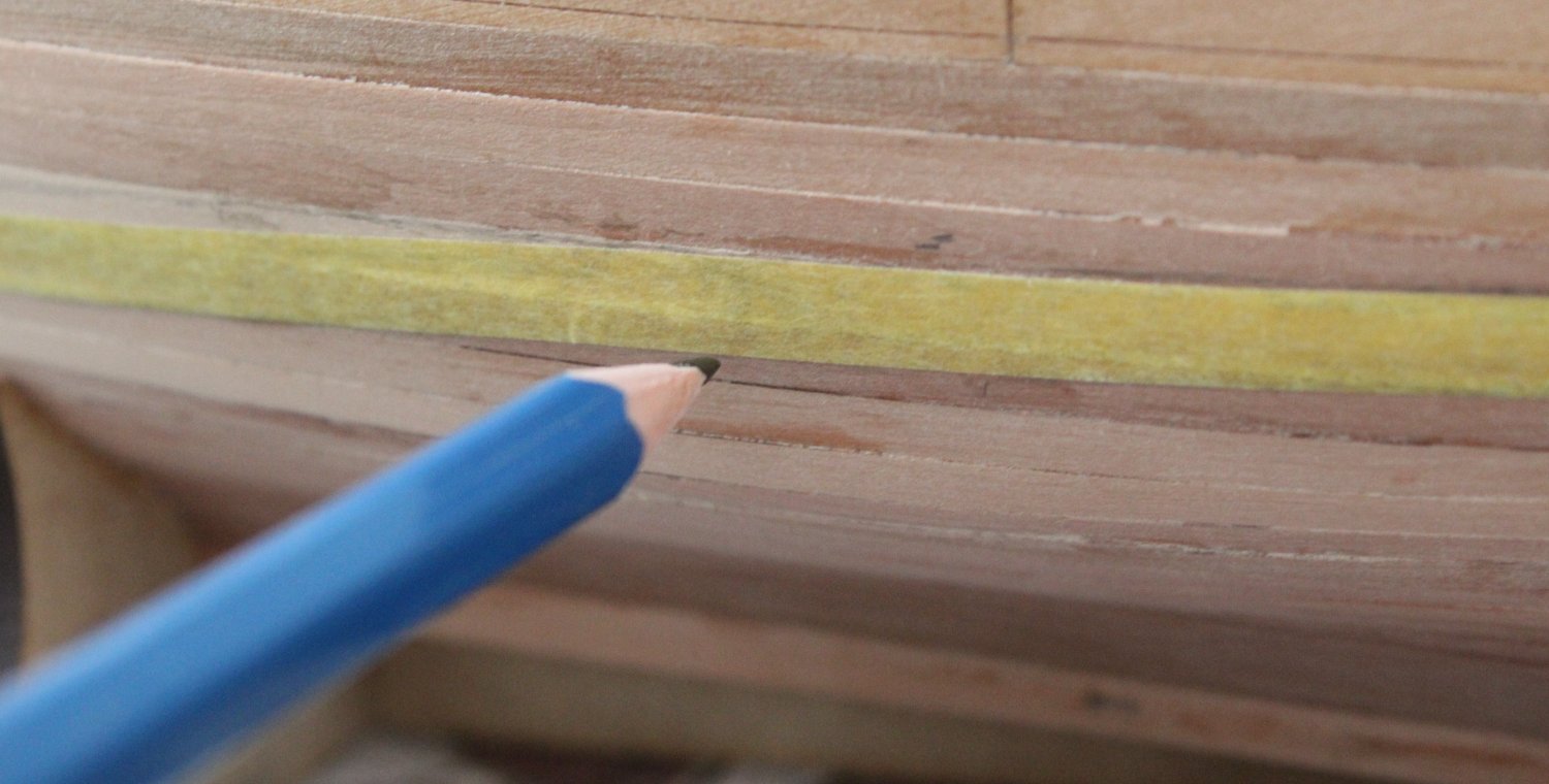
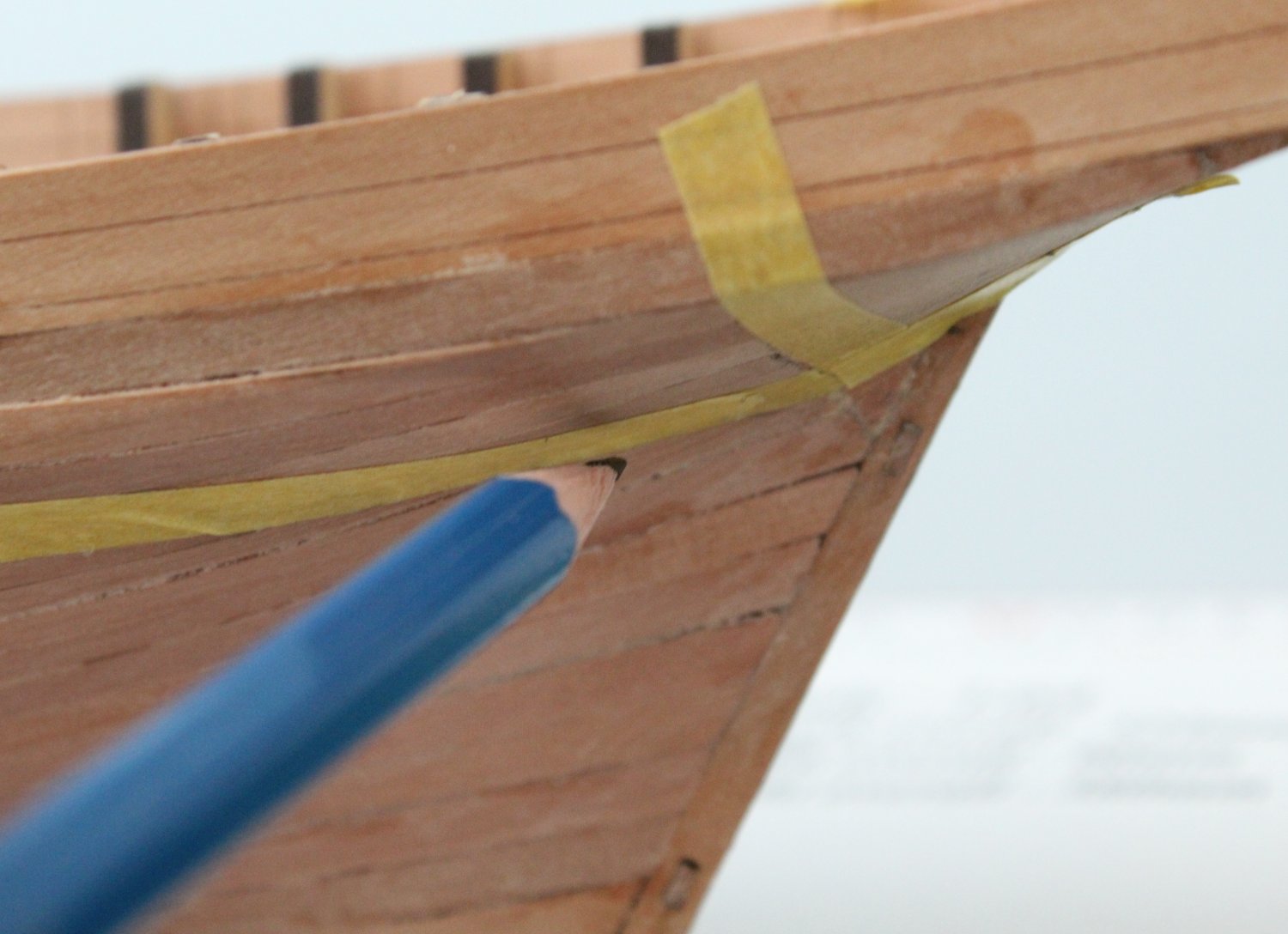
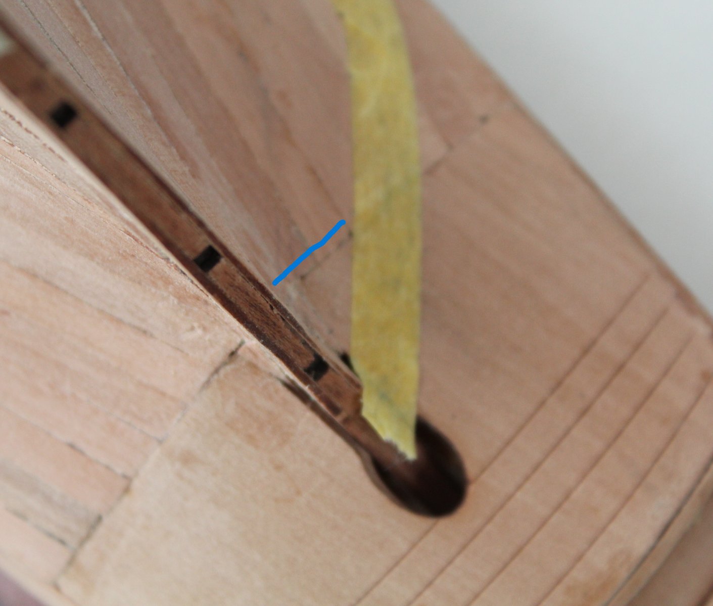
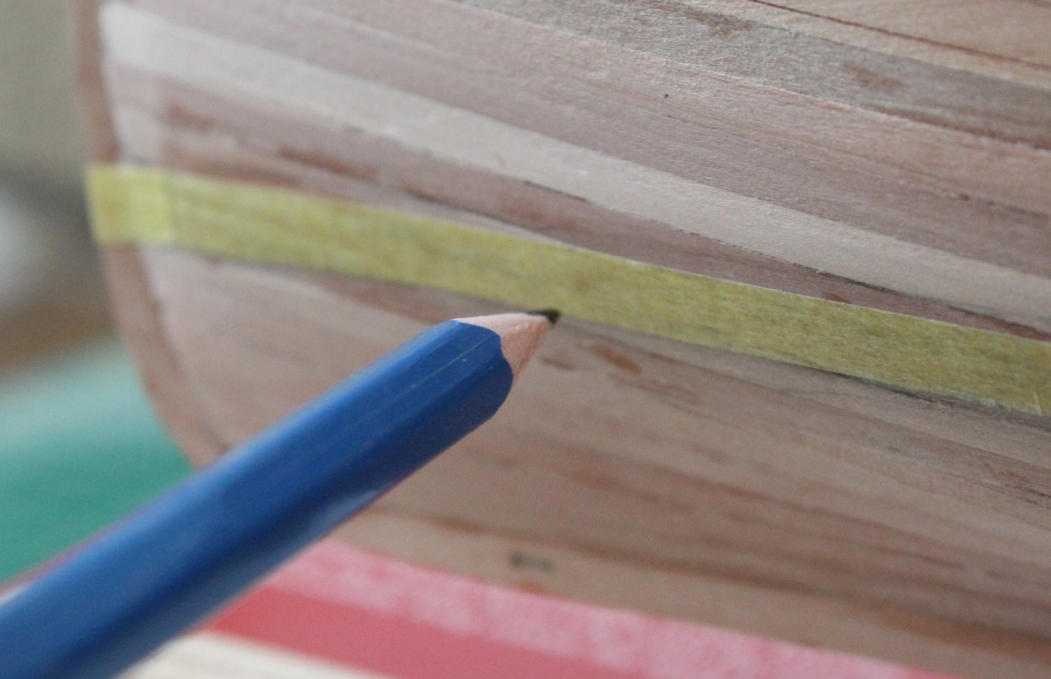
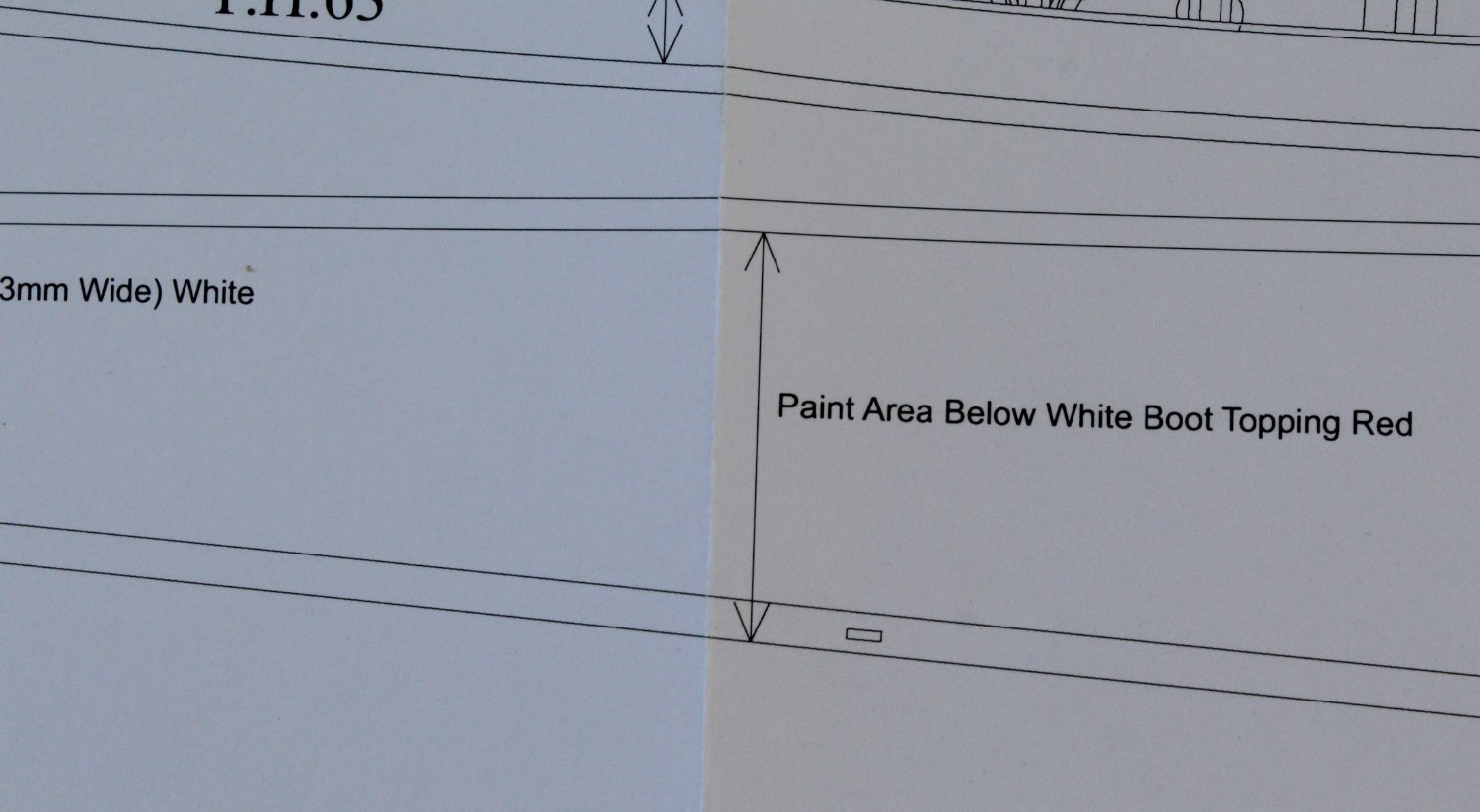
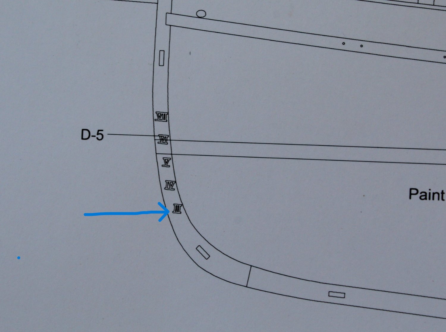
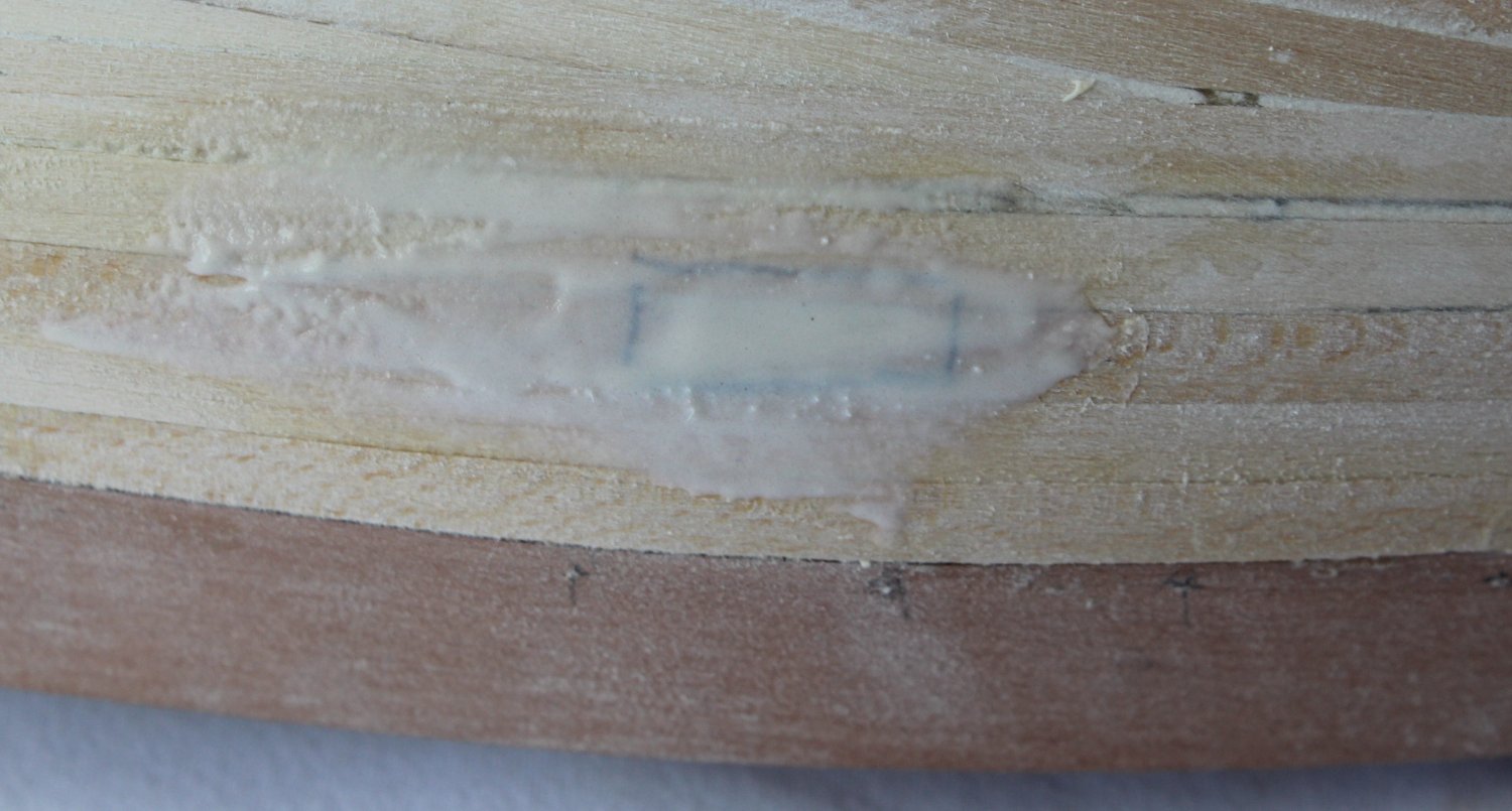
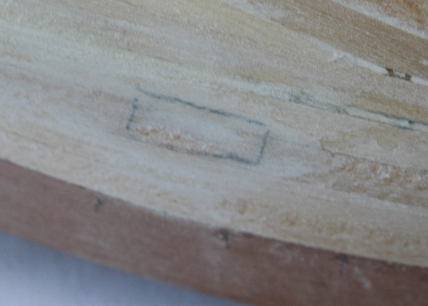
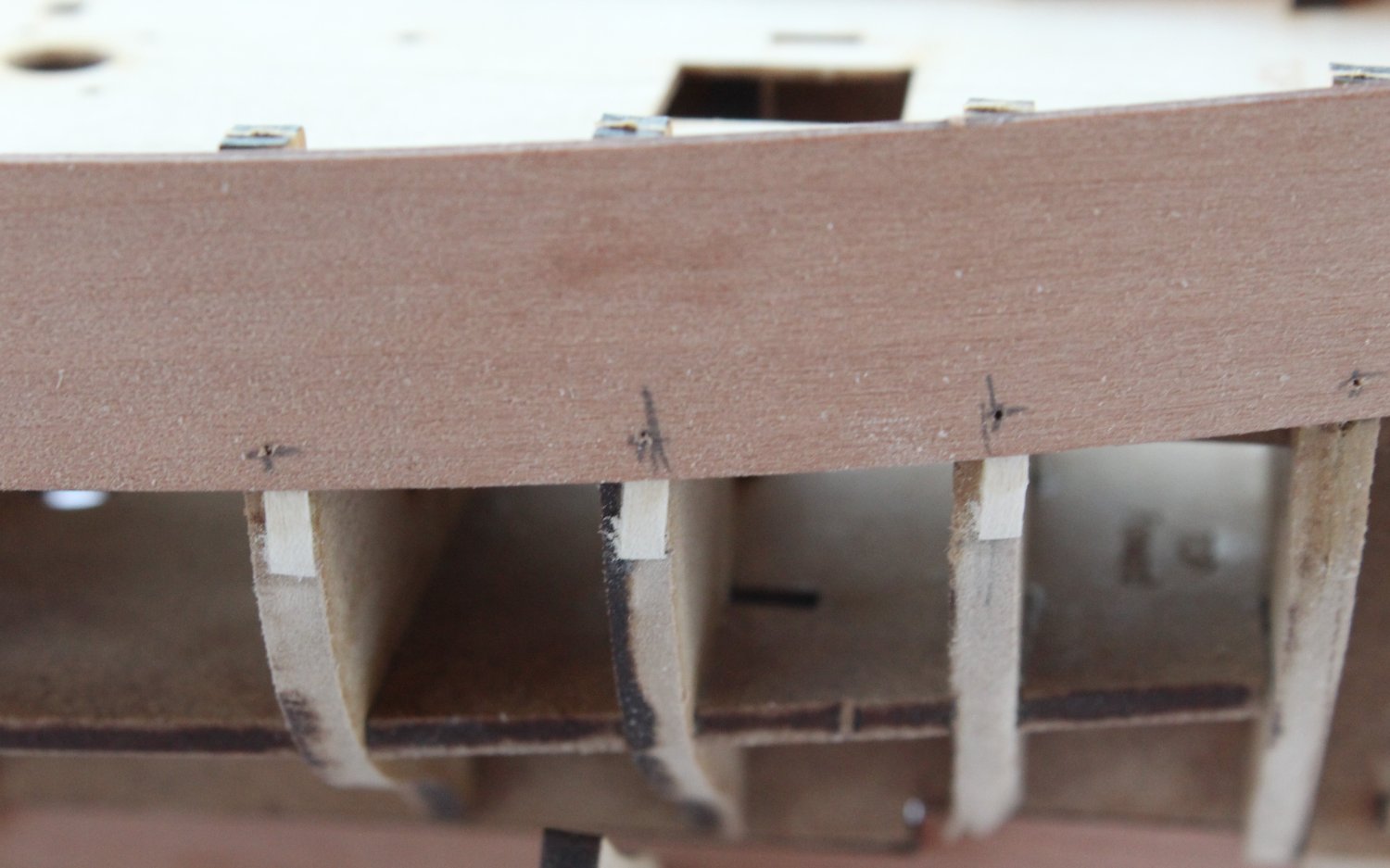
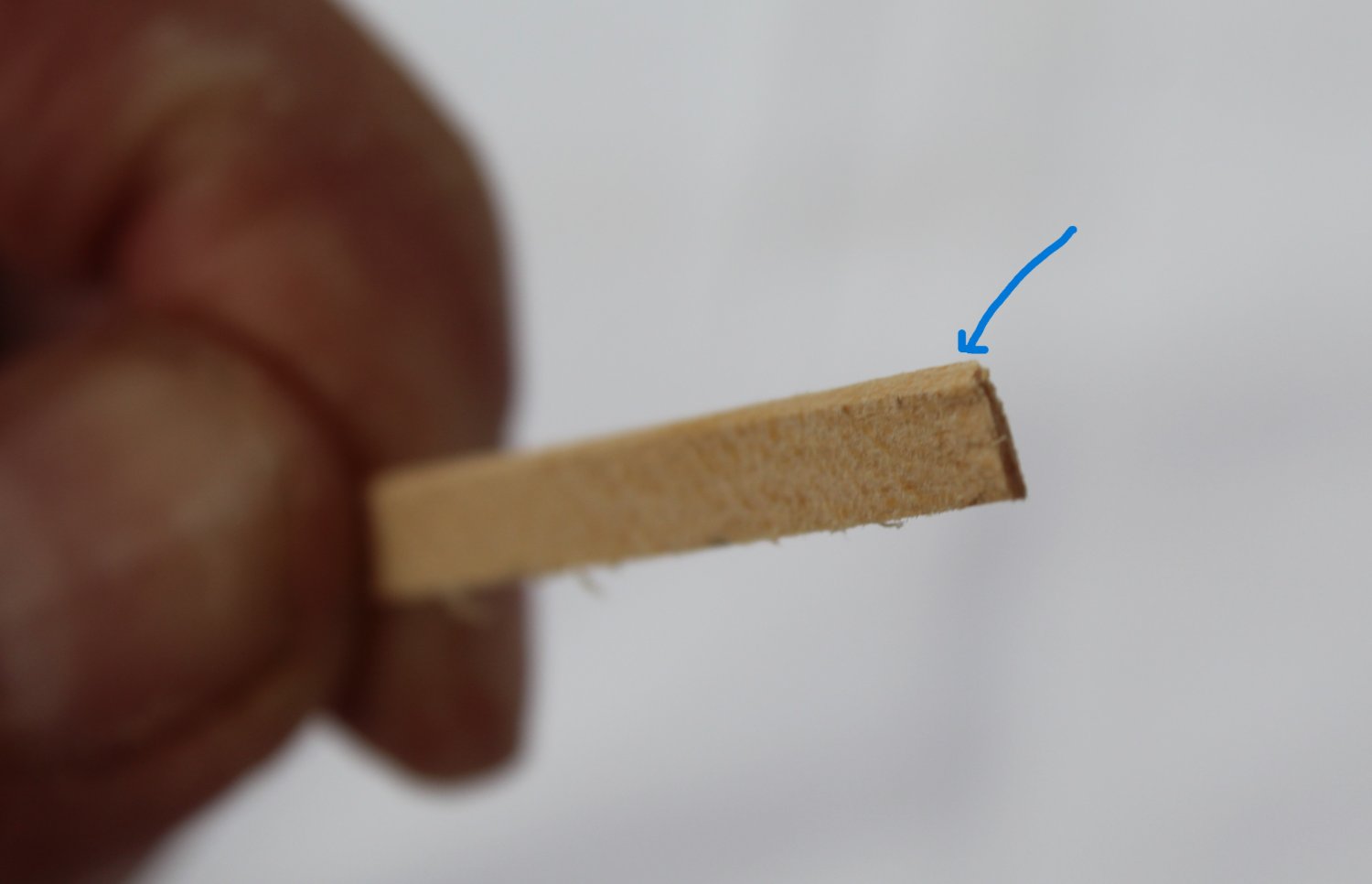
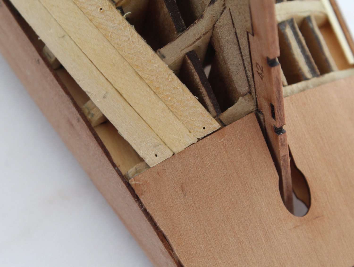
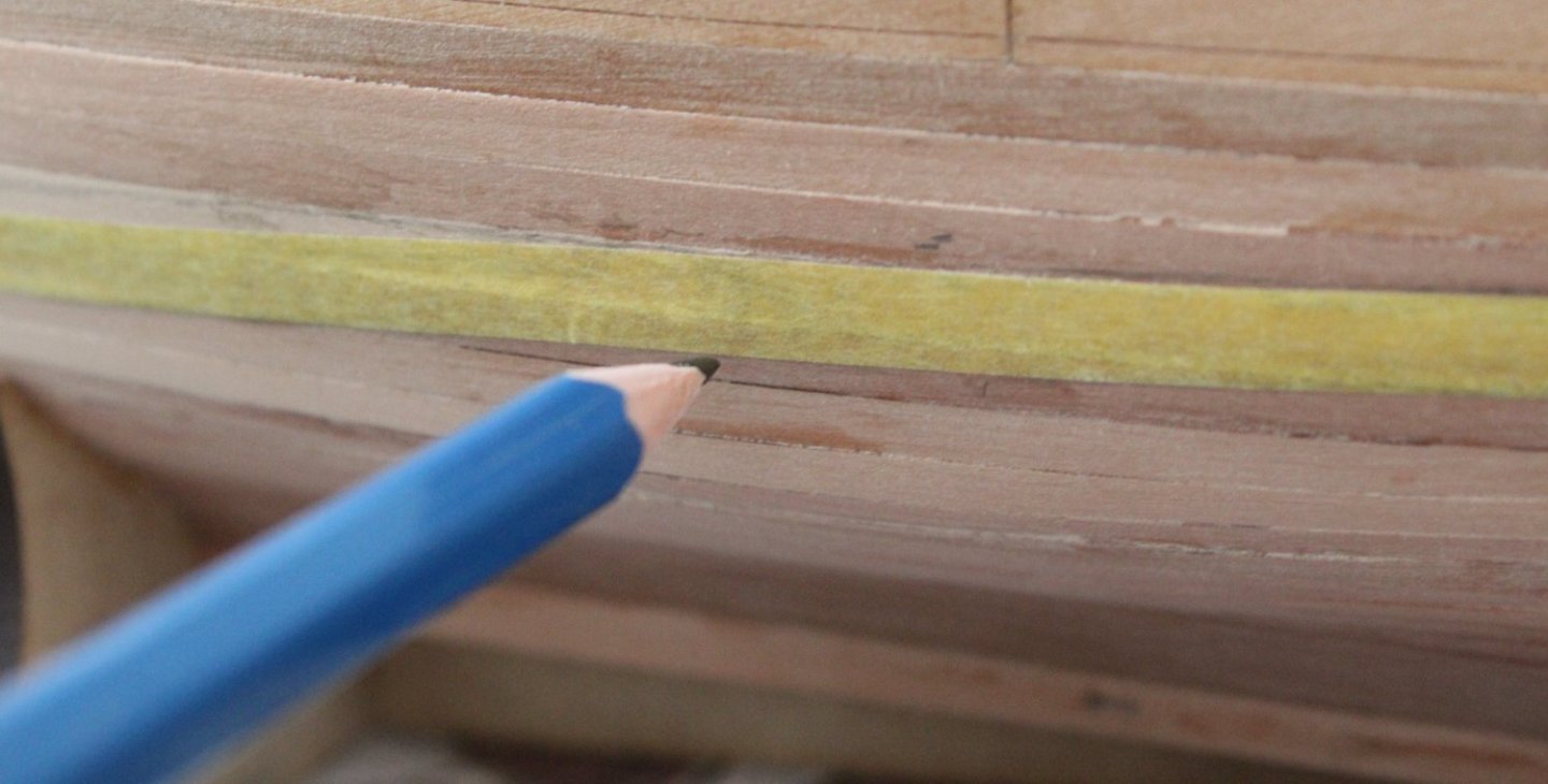
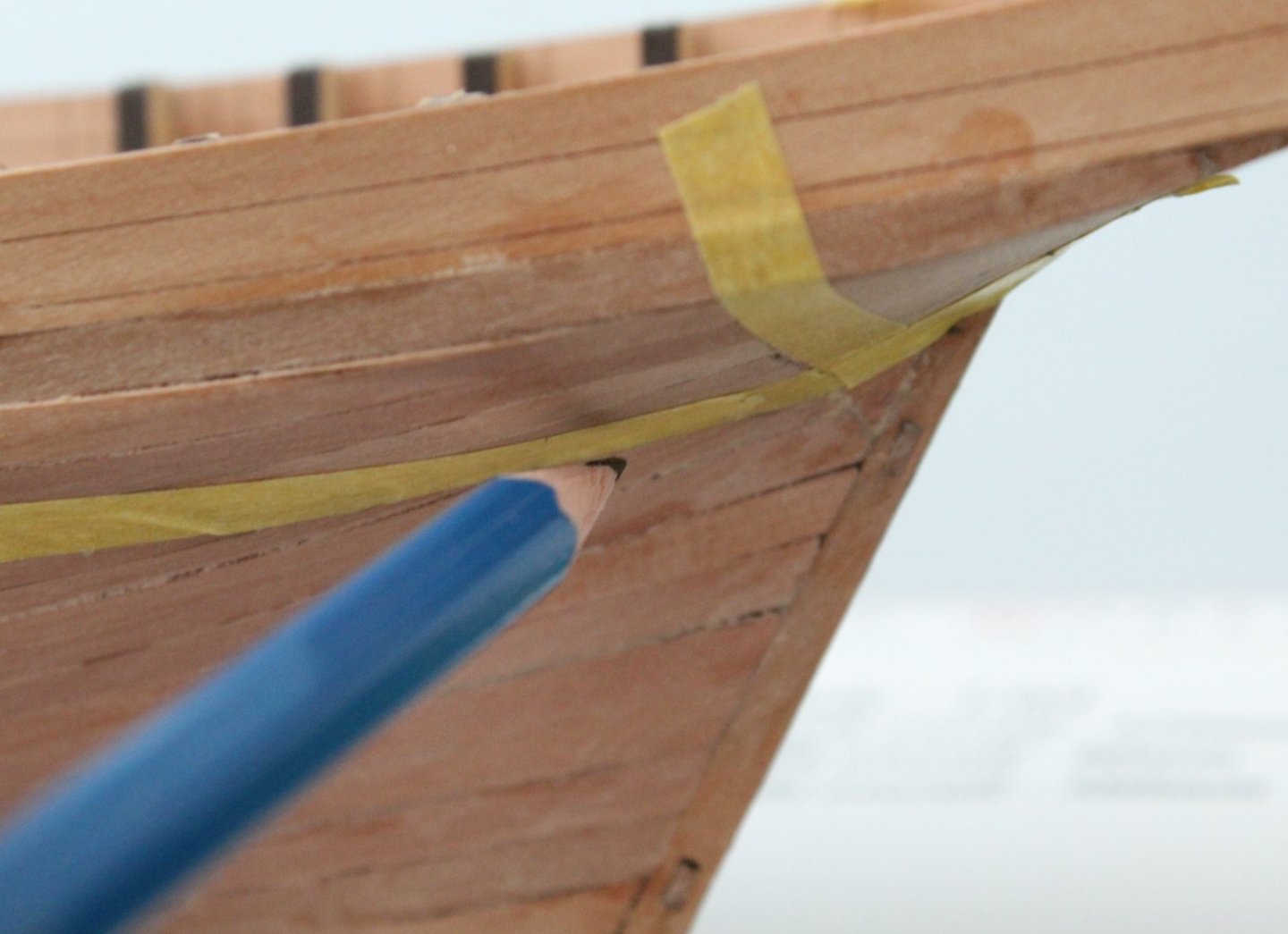
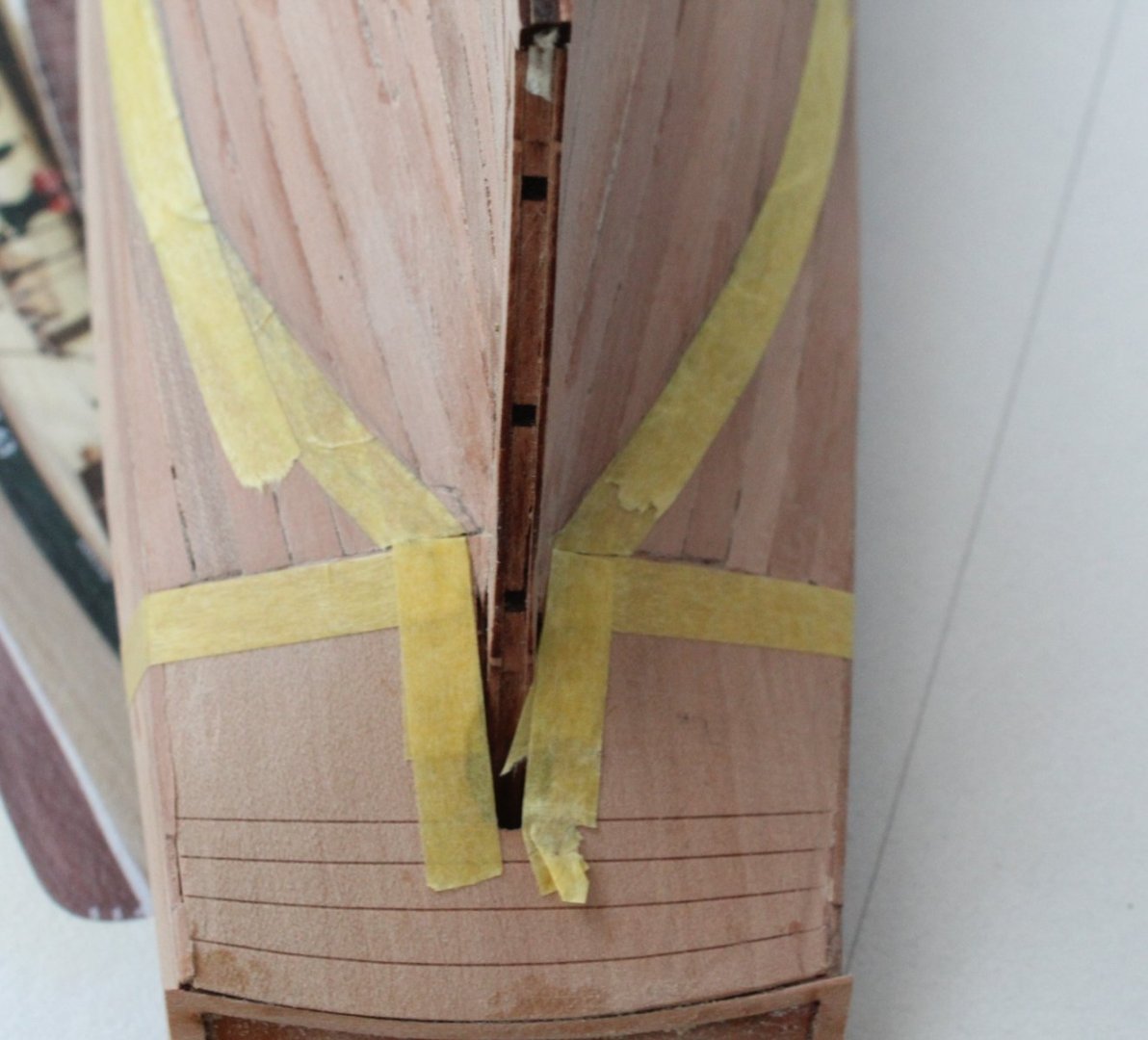
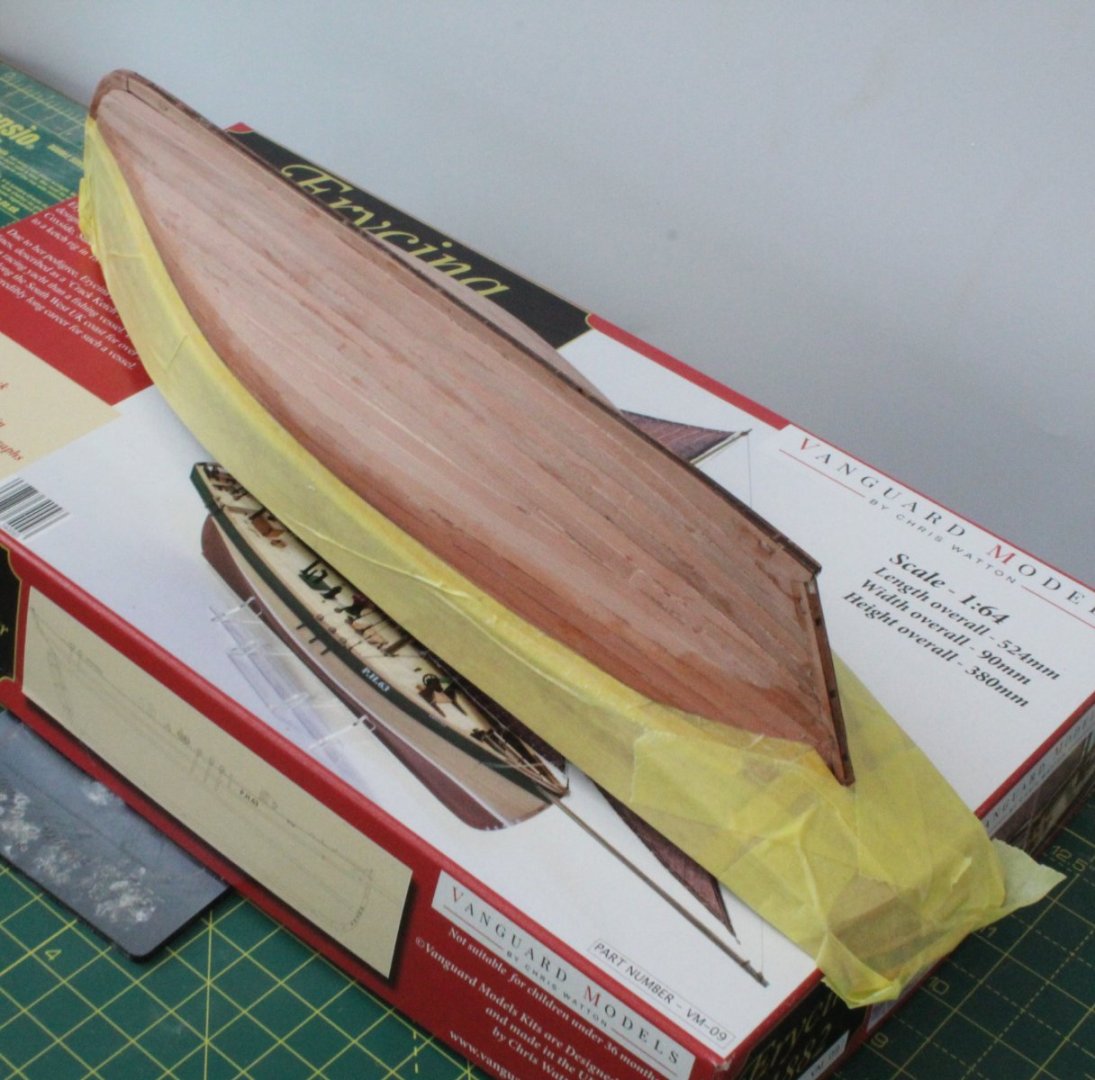
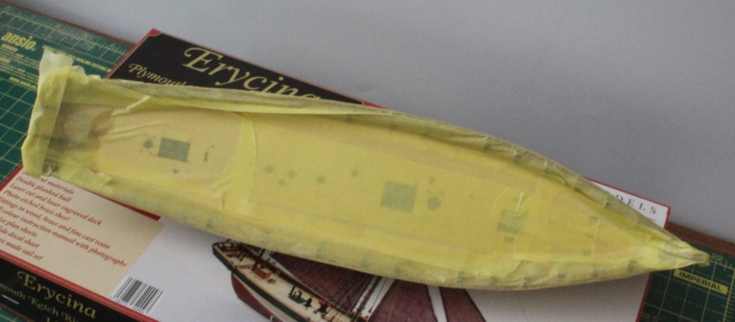
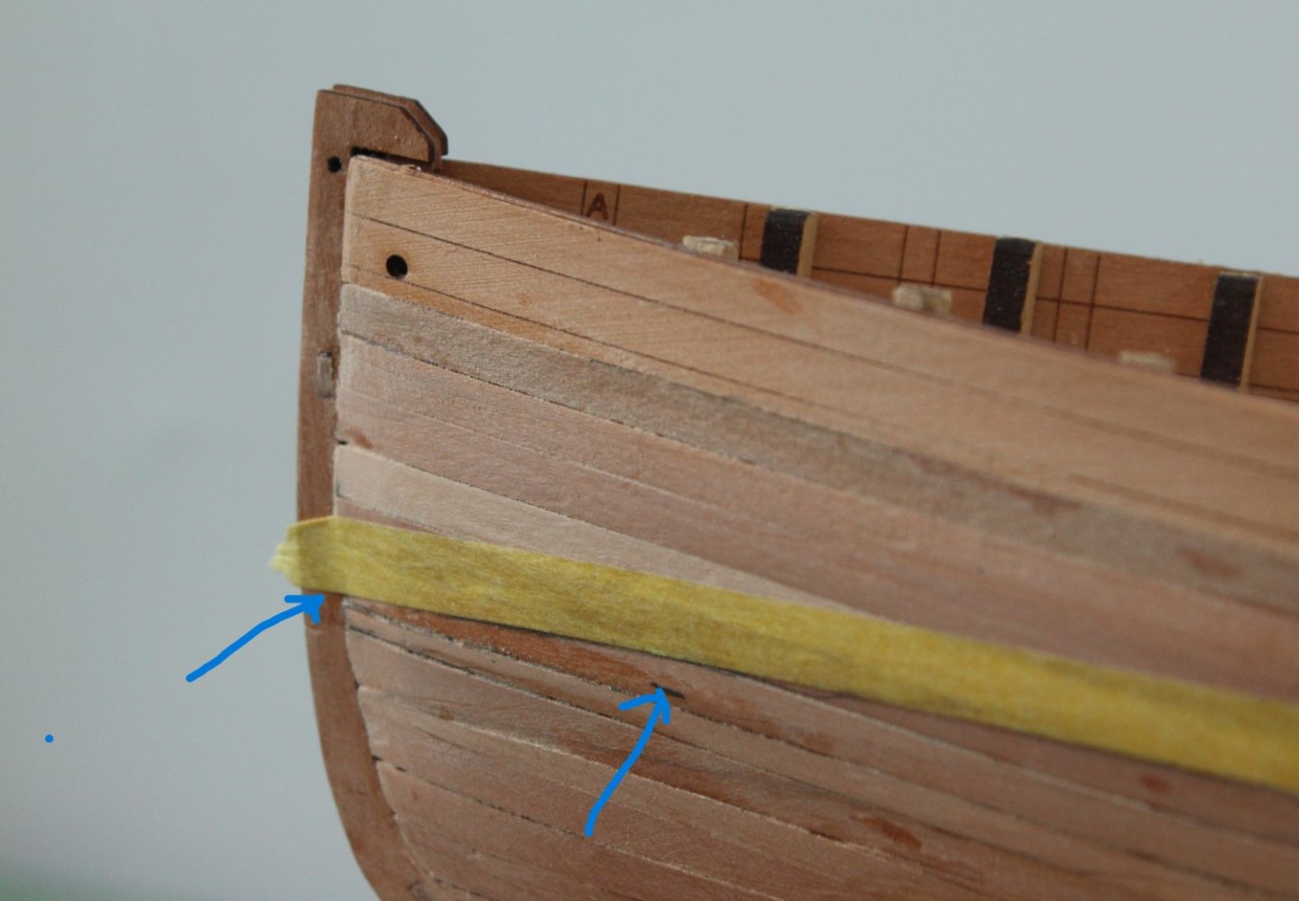
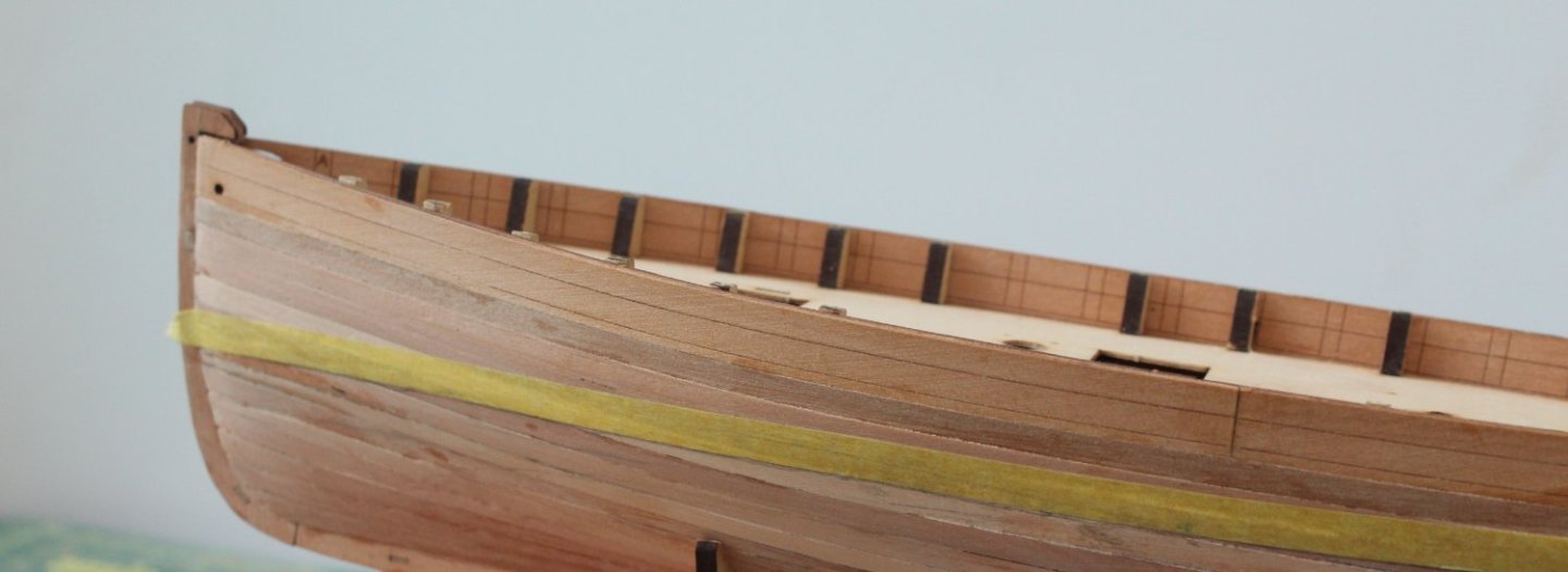
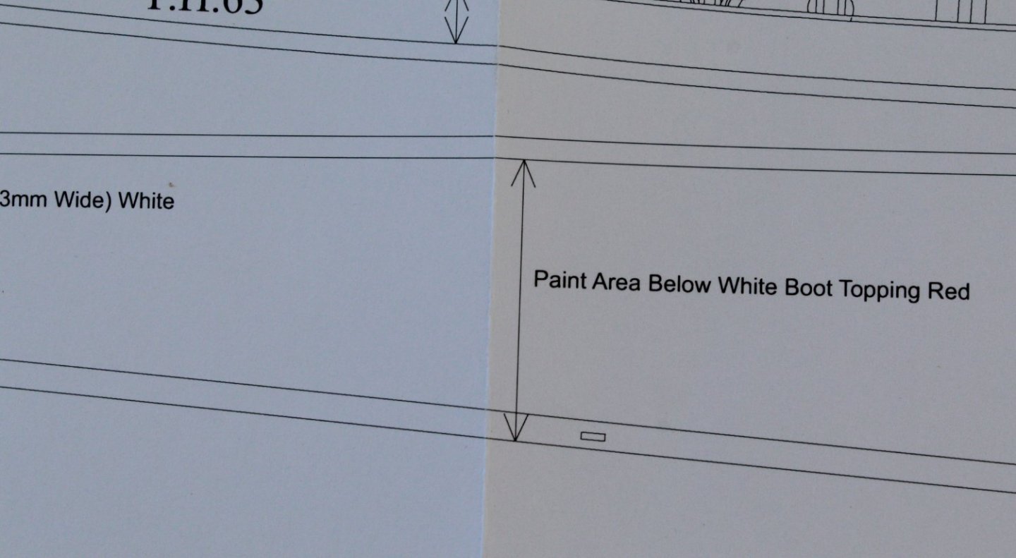
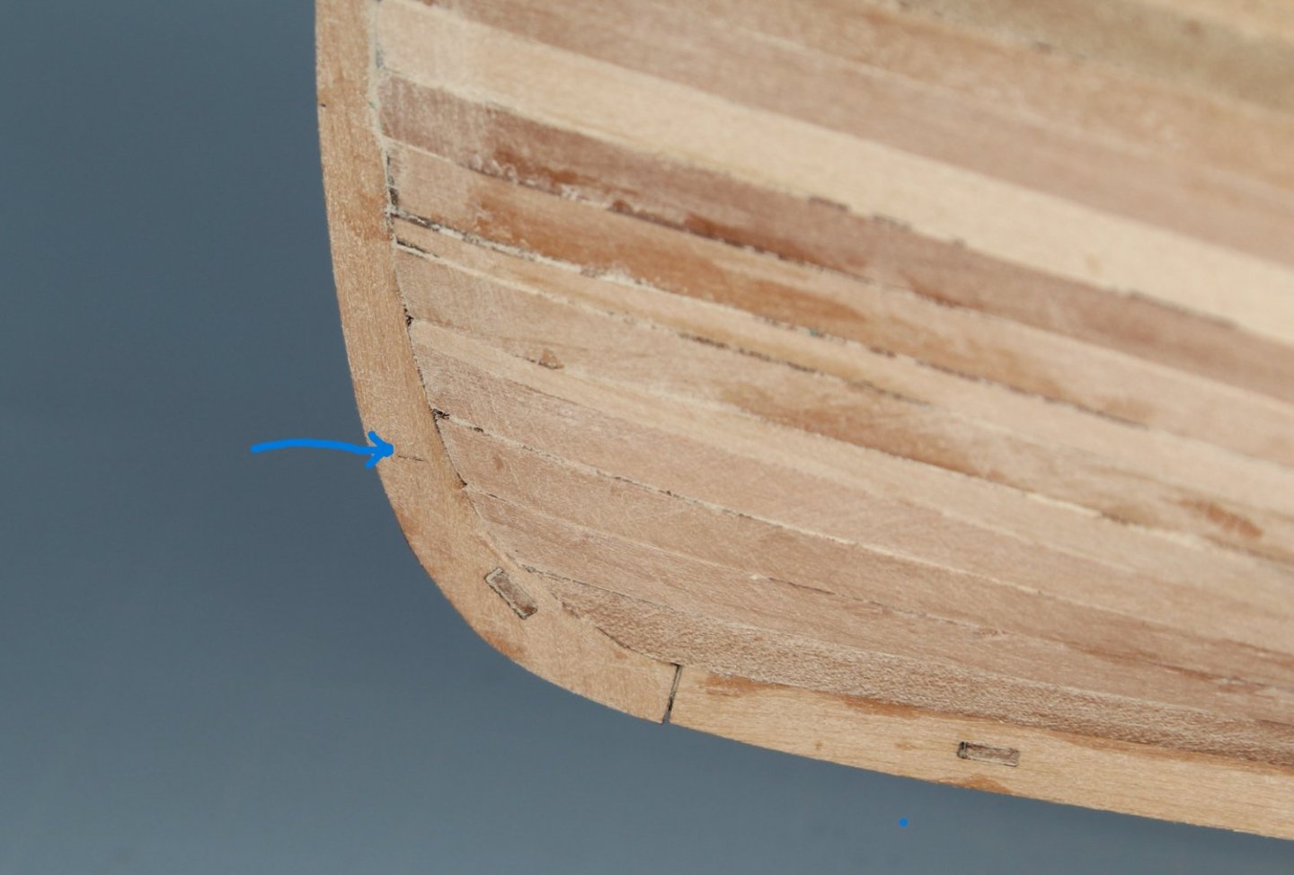
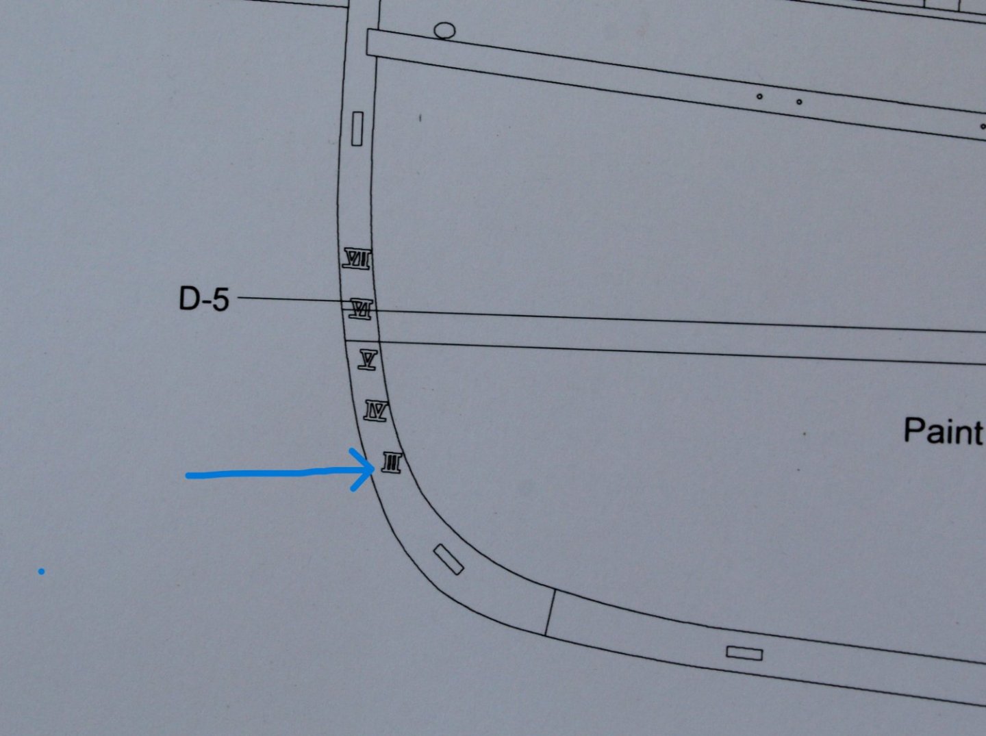
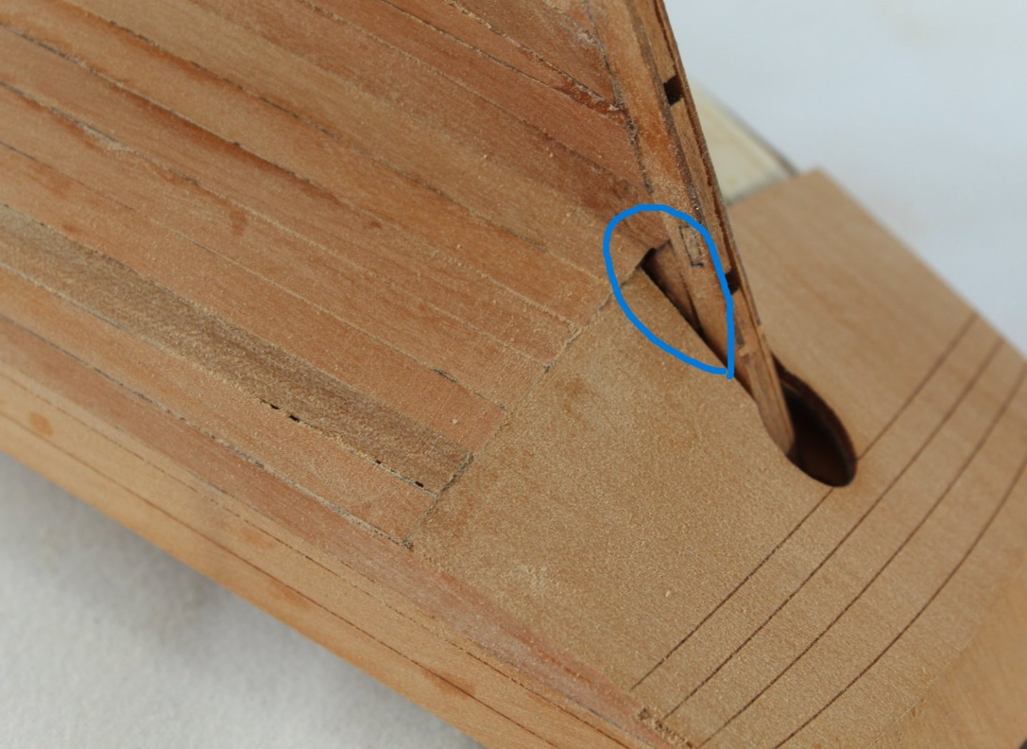
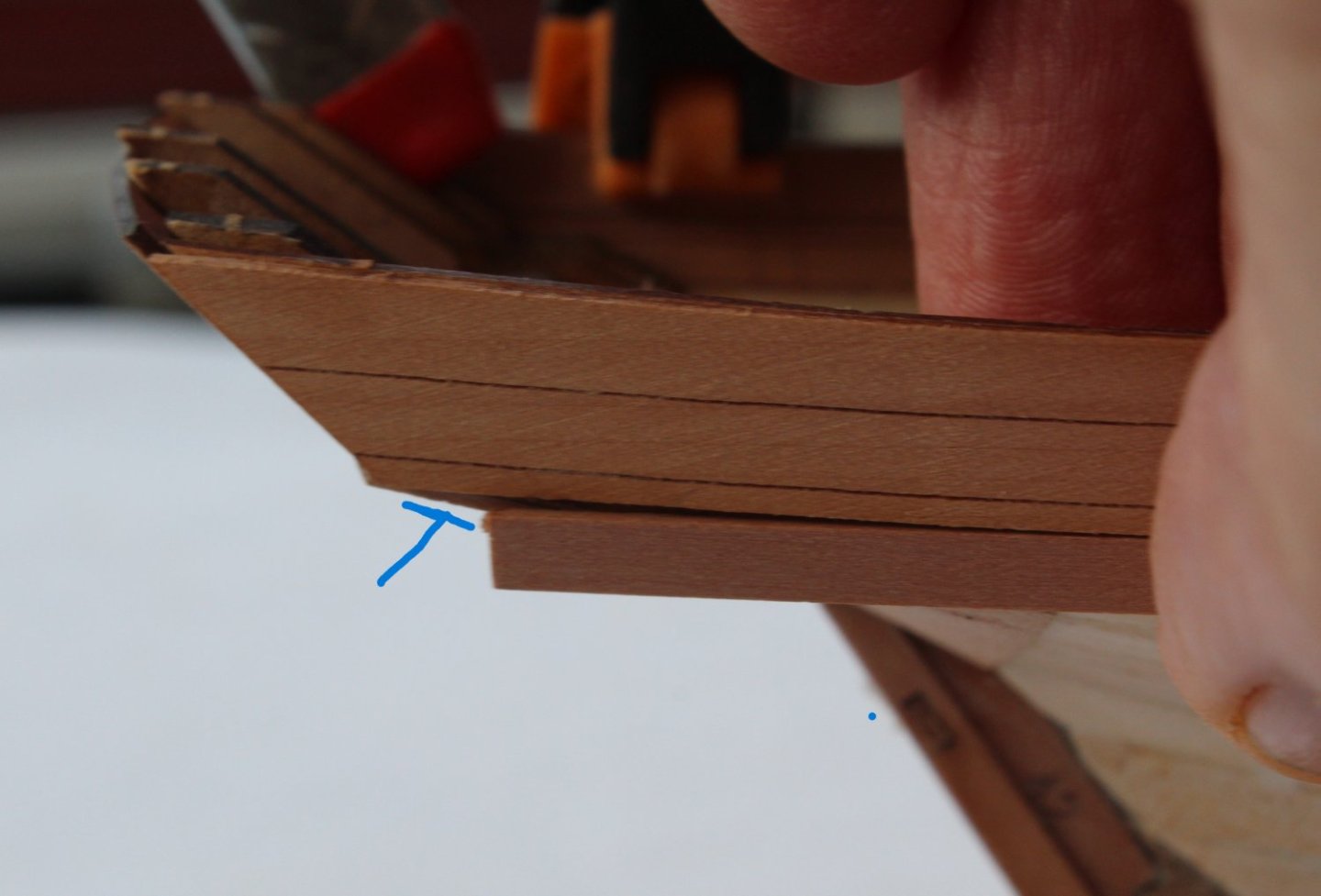
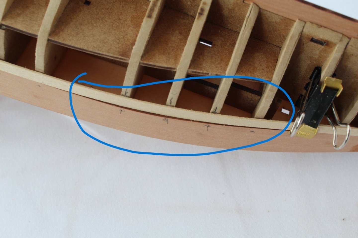
016 - Marking the Waterline I have jumped forward a bit with the build sequence as I wanted to paint the hull white below the waterline. This will highlight all the bumps and dips. I can then sort out all the defects prior to adding the deck pattern and painting the outer bulwark patterns. Adding the waterline should be a simple task to complete. Unsurprisingly this turned out to be more time consuming than I expected. This is because I over complicated this simple task by trying to be too clever. I have detailed what I did below. I started measuring, from the plan sheet, some points of reference to help with ensuring the waterline was correctly drawn. I transferred these measured reference points to the actual hull, using the scaling factor of 0.85. With all the point added and double checked I added a length of masking tape, joining the dots up from stem post to stern post. I then used my waterline marker tool to check the alignment of the bottom edge of the tape. The bottom edge of the tape did not track the same path indicated by the waterline marker tool. With the tape adjusted to following the same path indicated by the waterline marker tool I noted some of my reference points were visible, as can be seen in the following photo, The measured 2nd dot can be seen below the tape (blue arrow added). With the tape adjusted and checked once again with the marker tool the waterline position seems to be set. When I then looked at the stern post area there is clearly a major issue with the position of the waterline. The bottom edge of tape should be at the end of the counter pattern, The problem can be seen on the photo below, the bottom edge of the tape should be at the left-hand side of the blue line. I removed the tape and redrew the waterline, this time ensuring the start point was at the correct point at the stern post end. New masking tape was added, and I then double checked the bottom edge of the tape followed the path indicated by the waterline marker tool which it did. I am now happy with the position of the waterline. With the waterline marked on both sides the hull I used a steel rule to firmly press the tape edge into the hull. I then applied a coat of diluted titebond to the edge to seal the join and to further reduce the possibly of paint leakage under the tape The hull has now been masked and is ready for a light coat of white paint. I am going to wait for a couple of hours before adding the paint to give time for the diluted titebond to cure.


- 106 replies
-
- 3
-
-
- Erycina
- Plymouth Trawler
- (and 3 more)
-
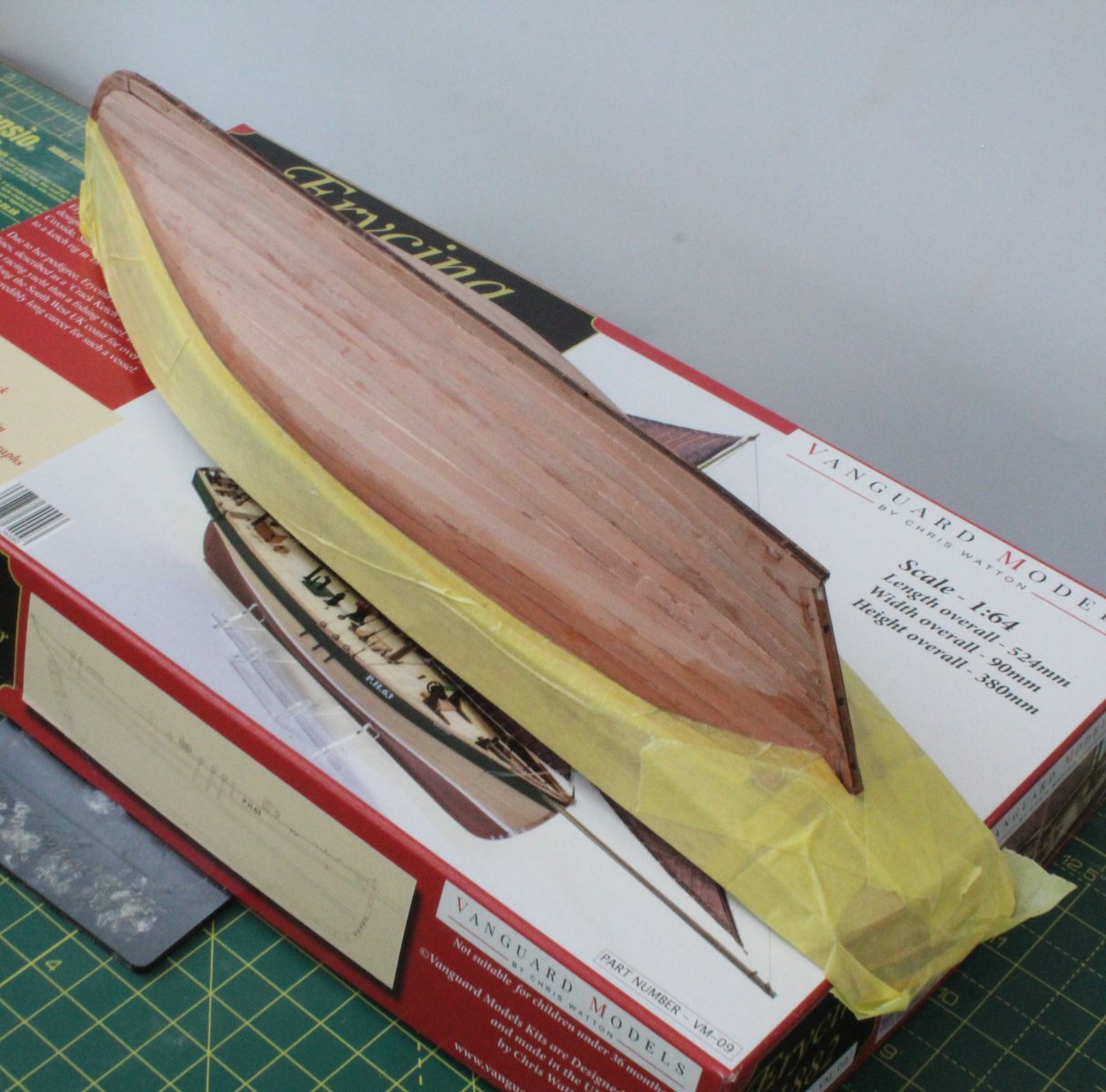
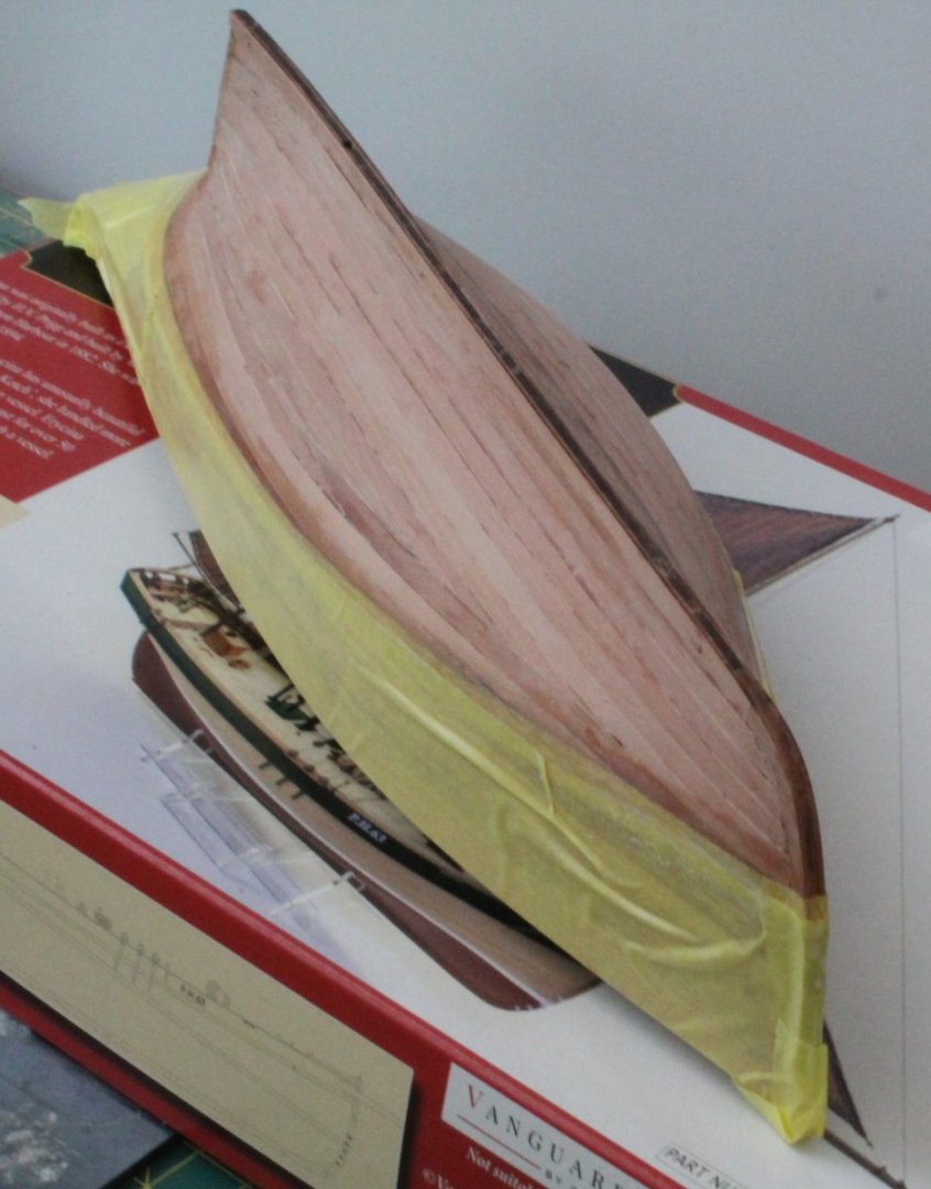
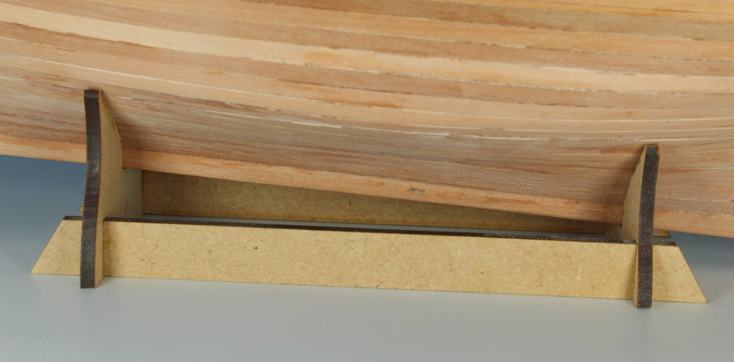
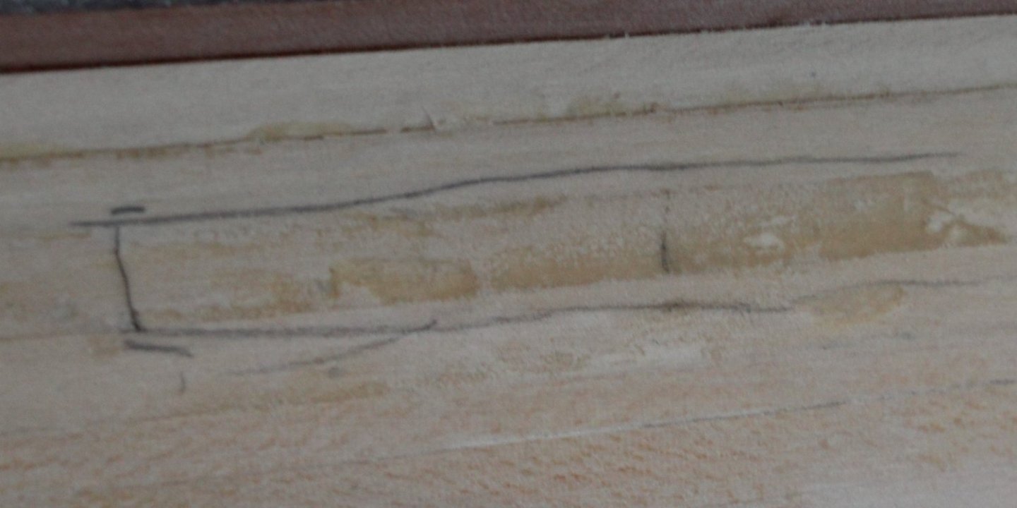
015 - Waterline Thoughts I thought I would add the waterline to the hull next. With the hull positioned in the stand with the aft stand peg securely located in the slot on the keel I was initially concerned that the keel was not level with the stand, as can be seen on the photo below. I noted the keel angle was correct when I checked the angle of the waterline with the keel on the plan sheet, as can be seen below. I then noted there was a mark on the stem post, as can be seen on the photo below. My first thought was this would indicate the waterline position. I soon discounted that as it lower than where I would expect the waterline to be. I confirmed this by scaling the waterline position off the plan sheet (using an 0.85 scaling factor) to get an idea of where the waterline would be on the stem post. I concluded the mark on the stem post would indicate the start of the waterline load marking decals.
- 106 replies
-
- 3
-
-
- Erycina
- Plymouth Trawler
- (and 3 more)
-
Many thanks, painting the hull is great for showing up the imperfections.
- 106 replies
-
- 1
-
-
- Erycina
- Plymouth Trawler
- (and 3 more)
-
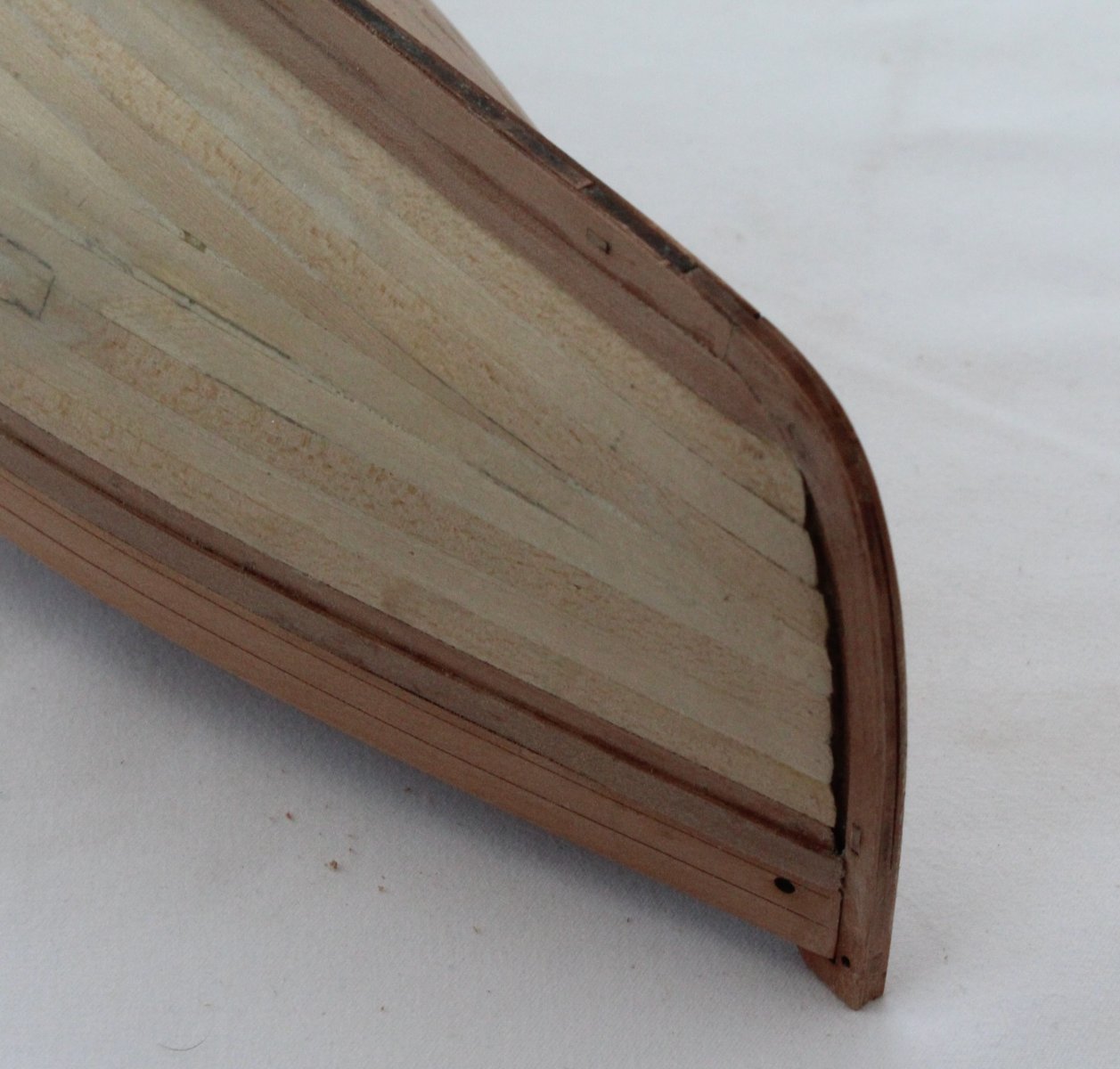
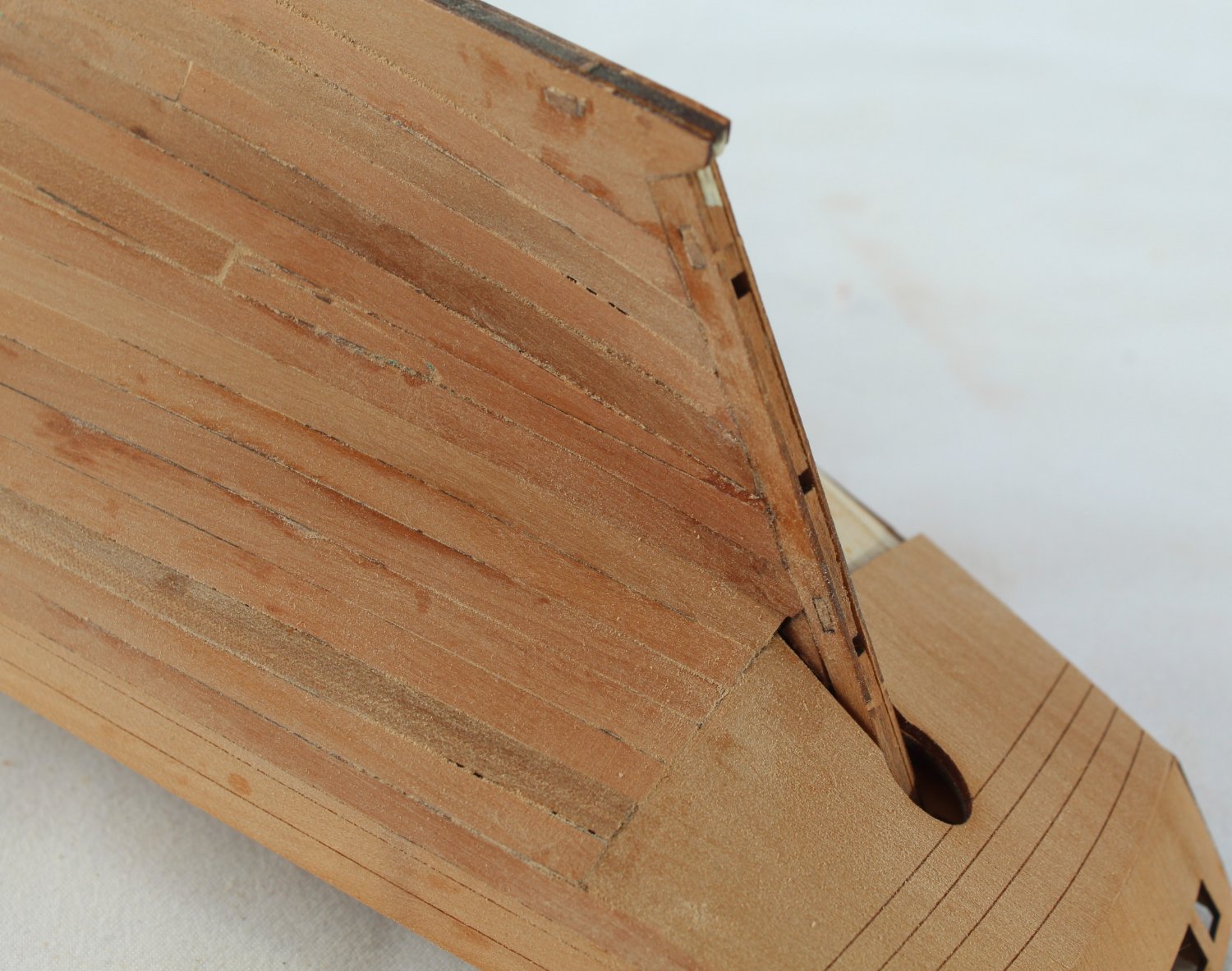
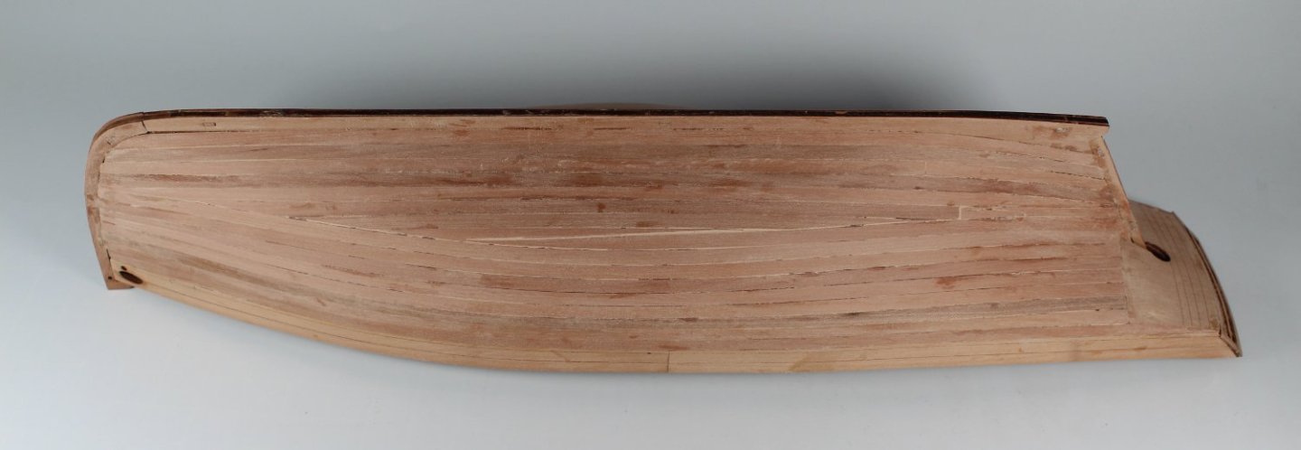
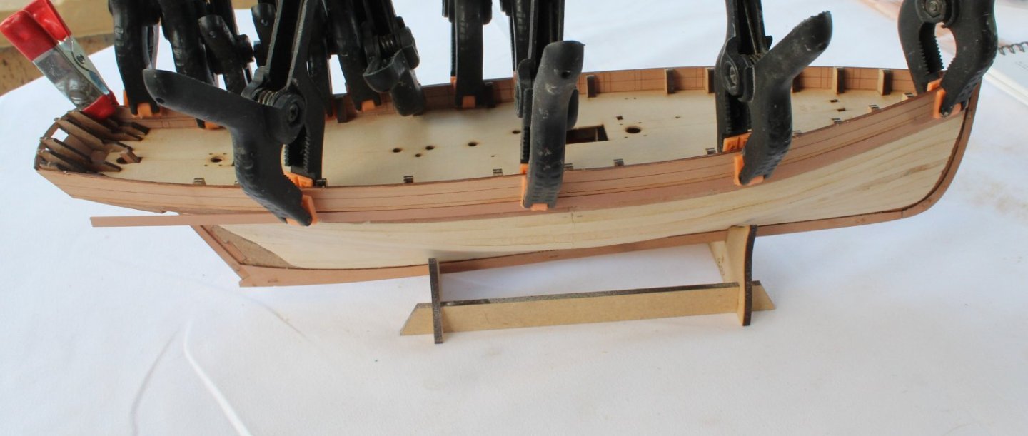
014 - Completion of Second Planking I have now completed the second planking of the left-hand side. The hull has also been sanded smooth, starting with 120 grit sandpaper and finished with 320 grit sandpaper. Although the hull looks and feels smooth, I am sure that when I apply a coat of white primer to the hull (below the waterline) there will be a few areas requiring further attention to correct before the final coats of paint can be applied.
- 106 replies
-
- 7
-
-
- Erycina
- Plymouth Trawler
- (and 3 more)
-
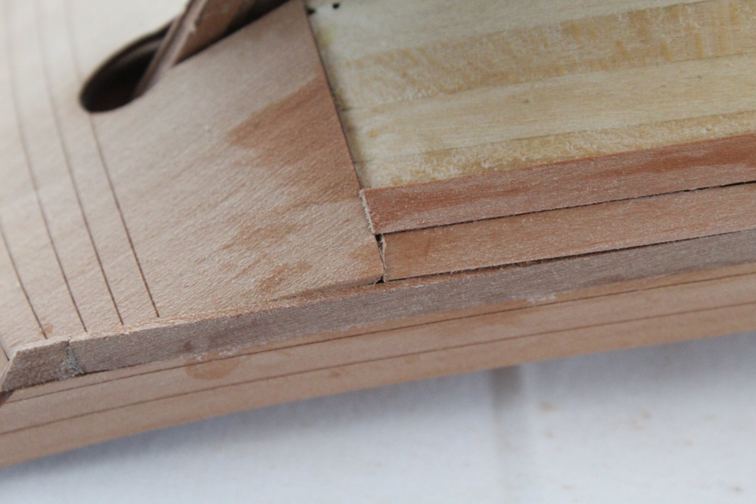
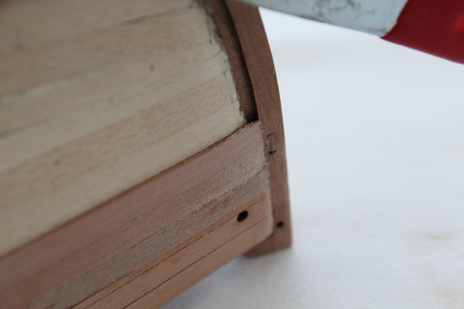
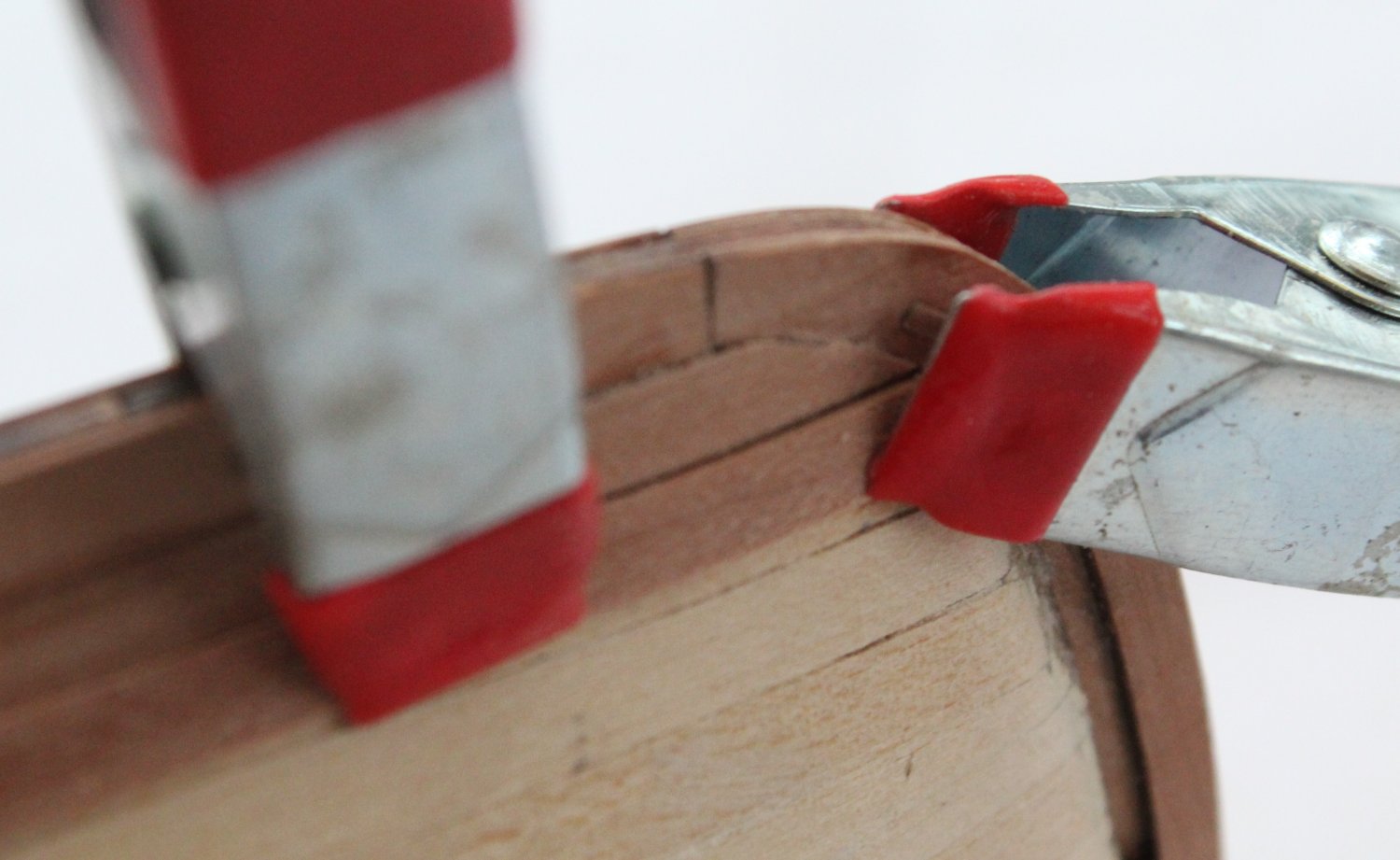
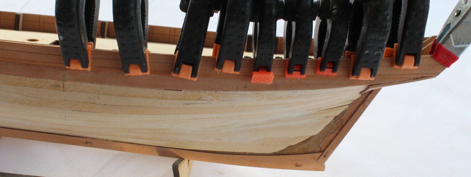
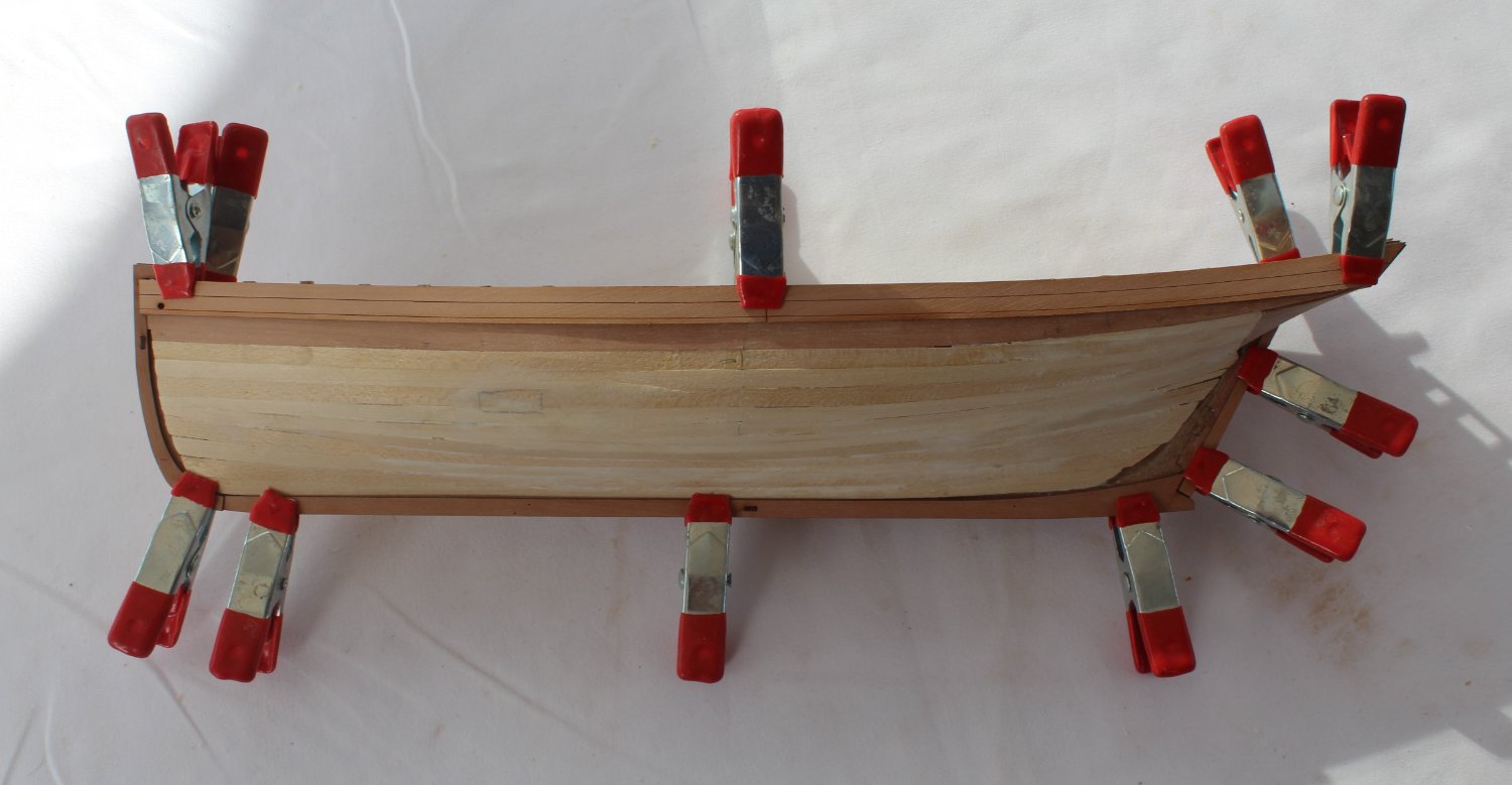
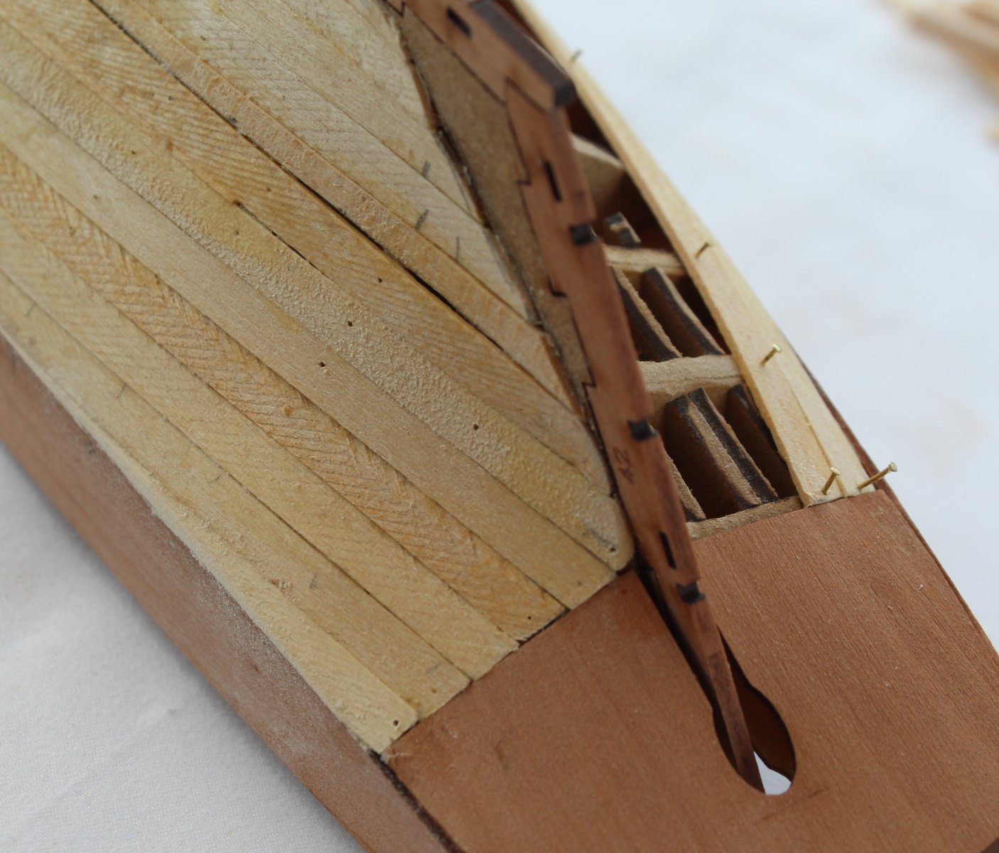
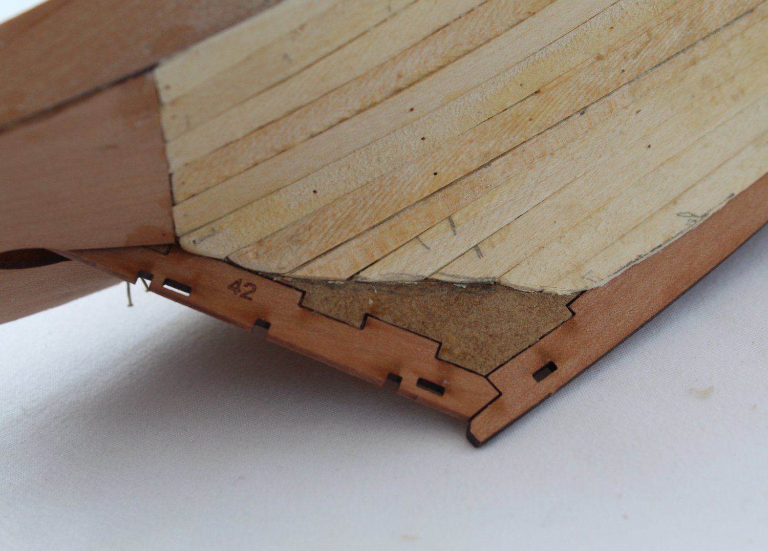
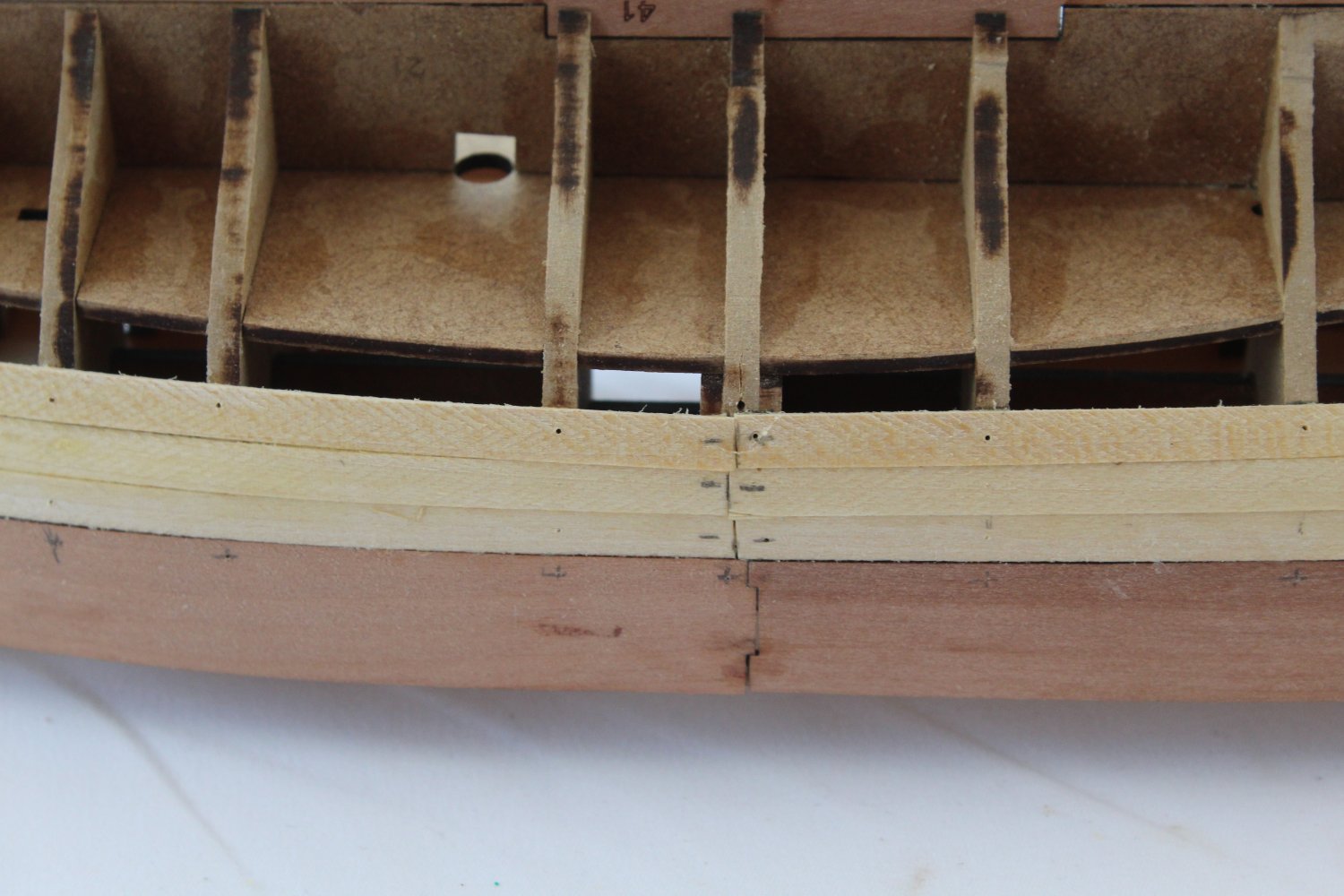
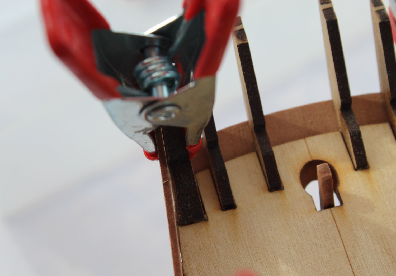
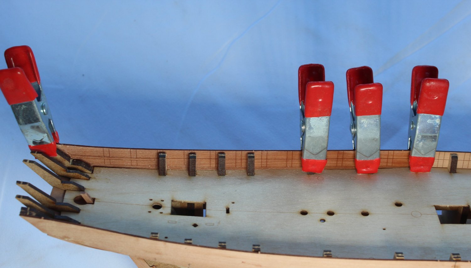
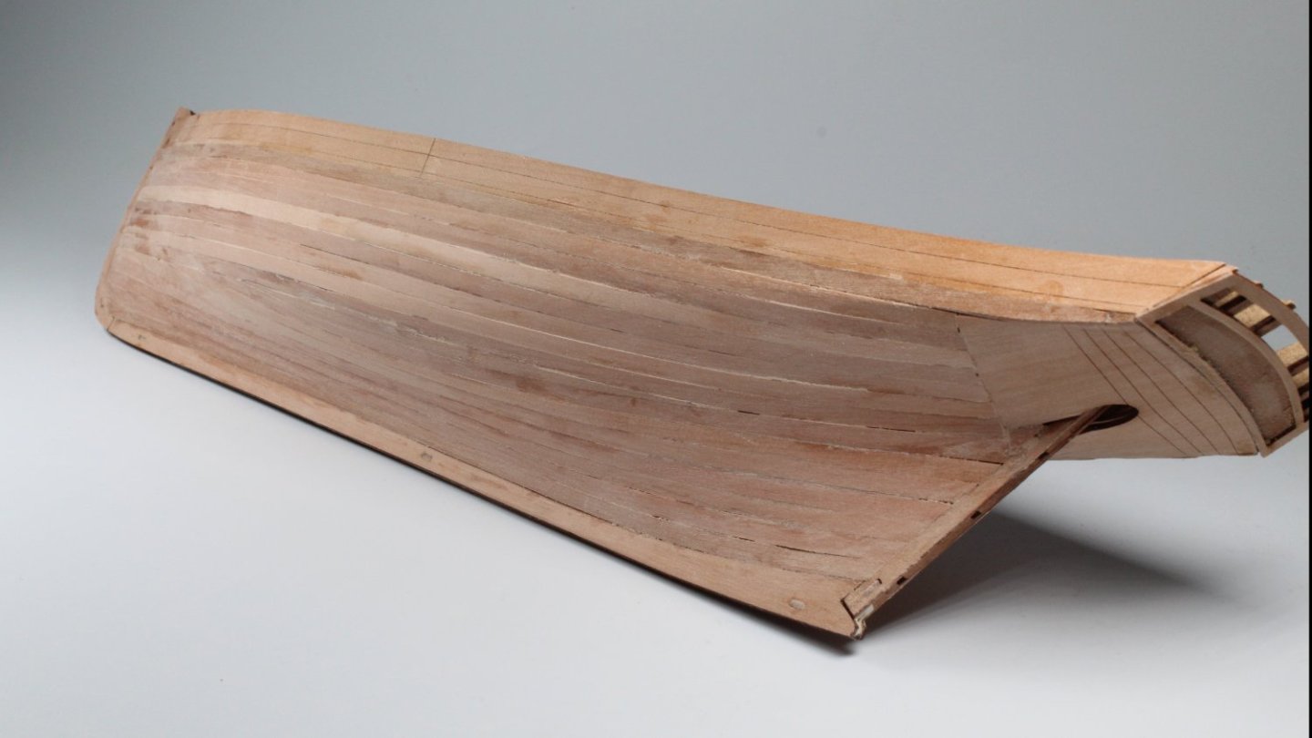
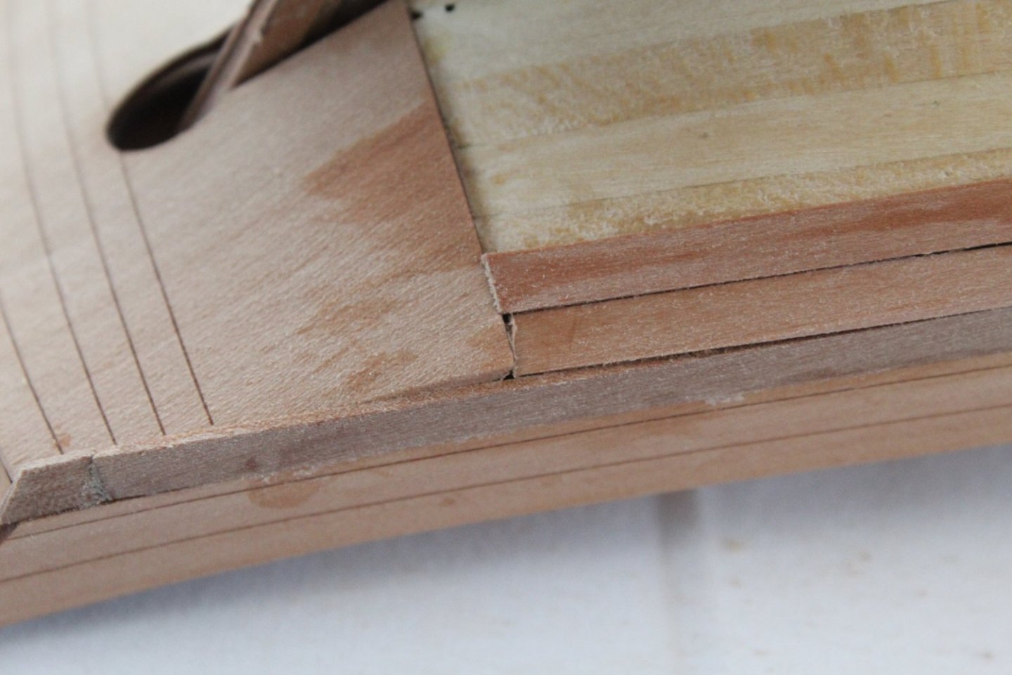
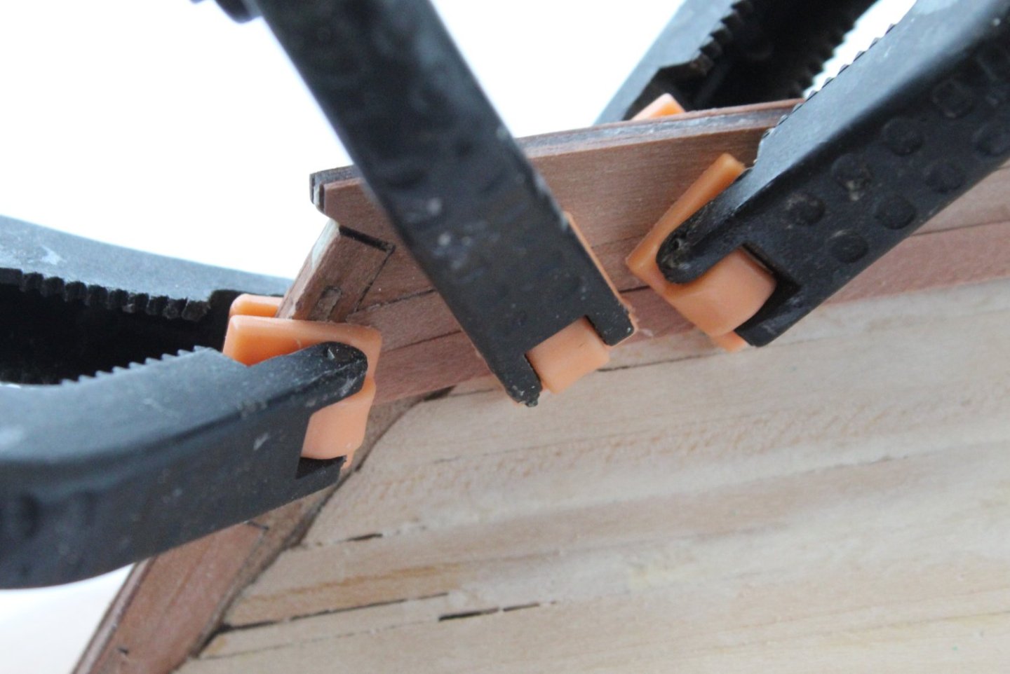
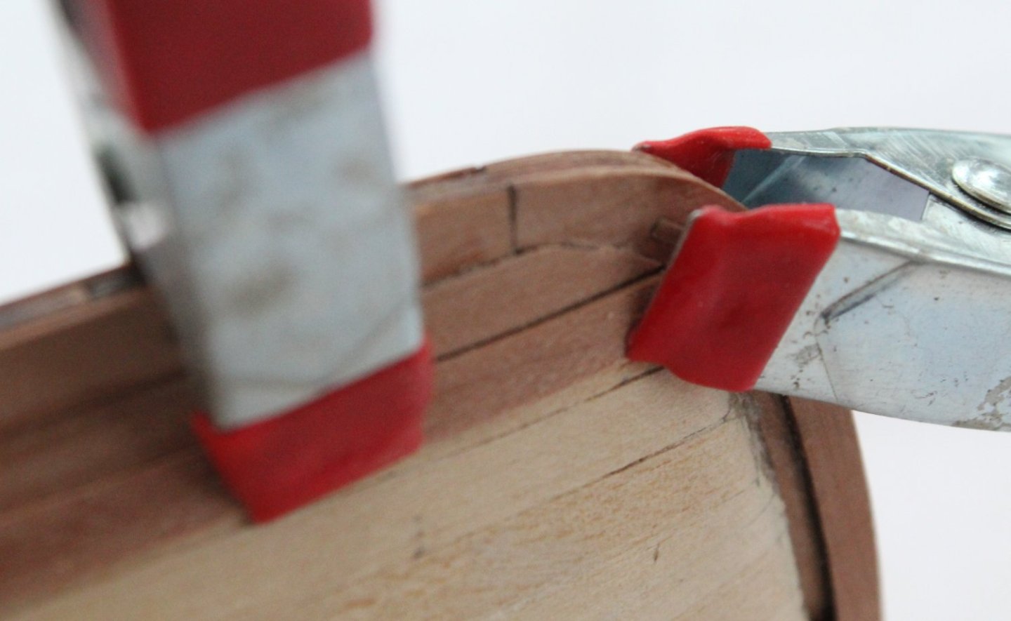
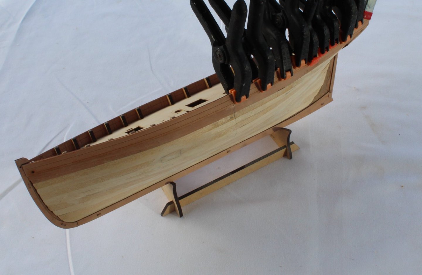
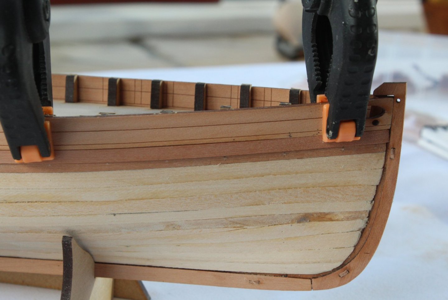
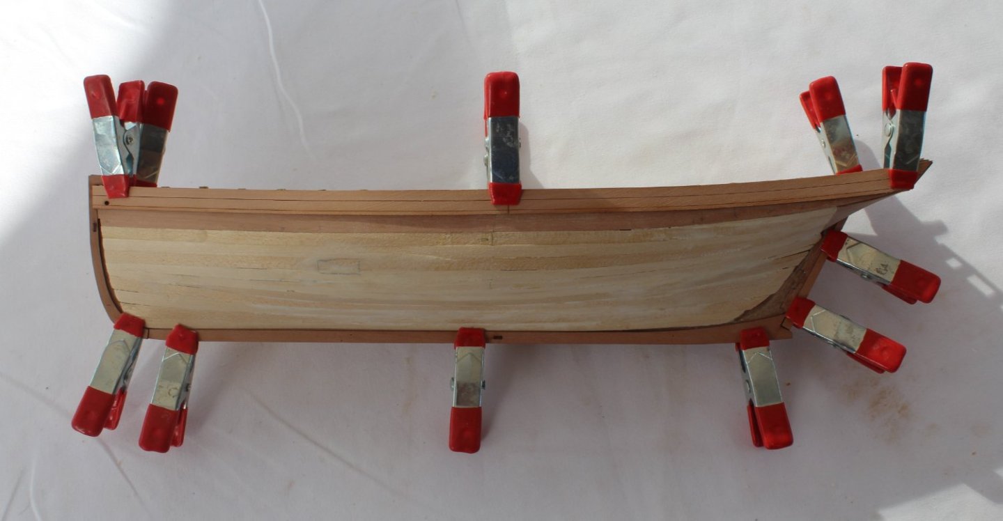
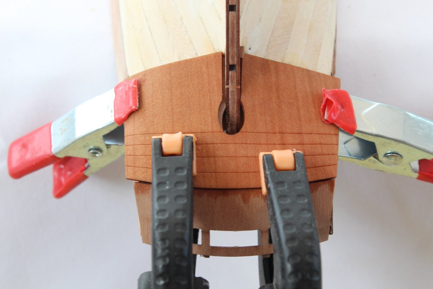
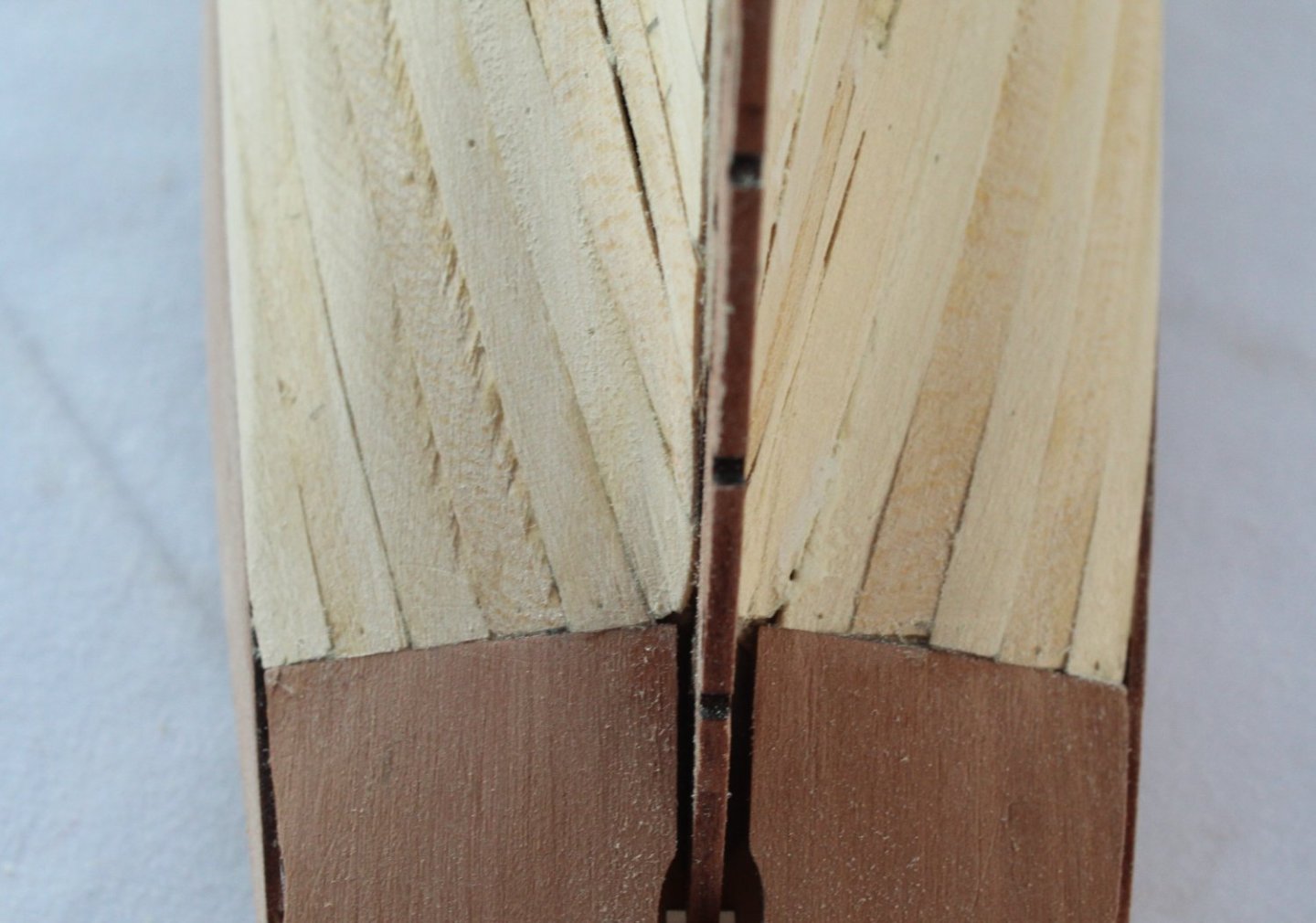
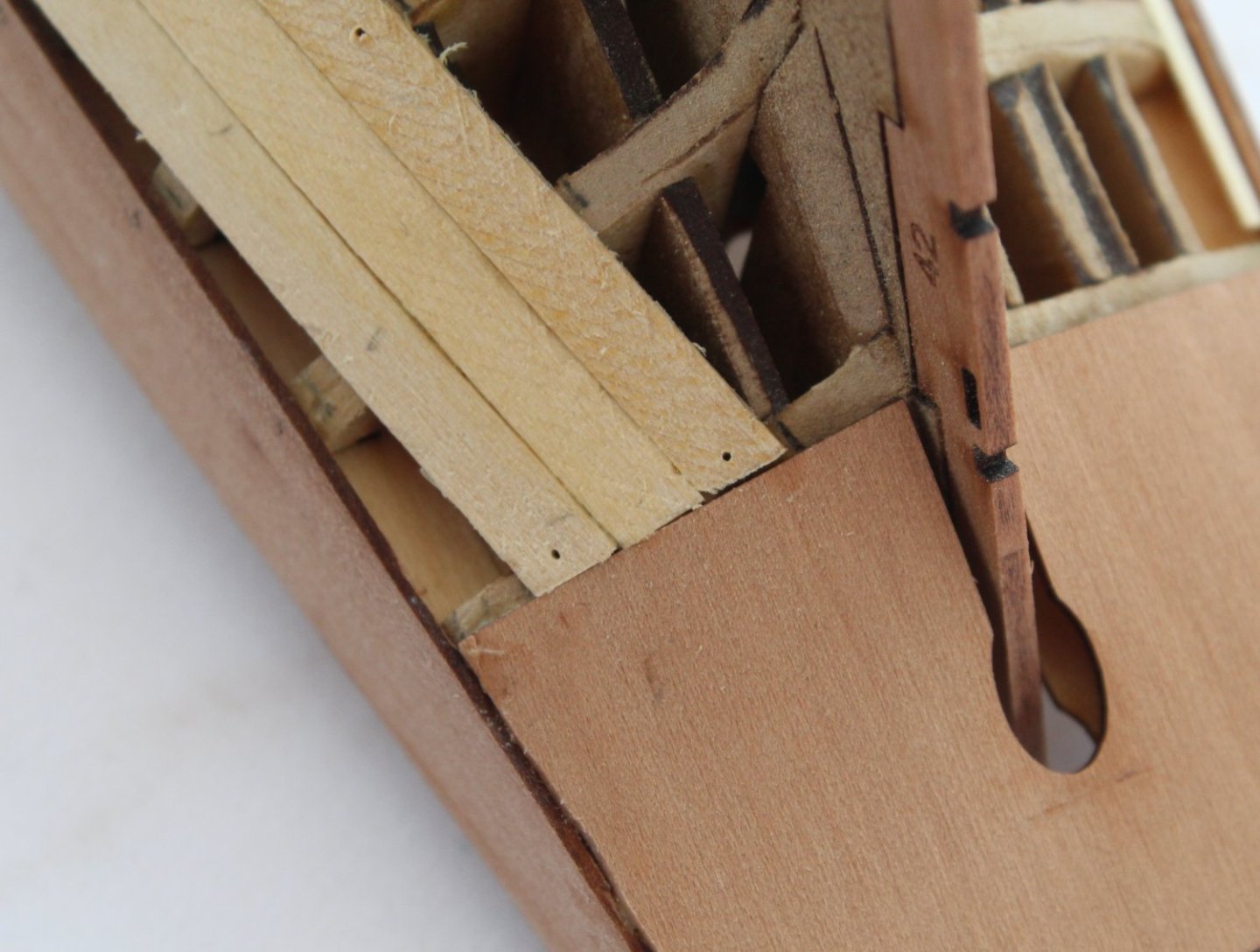
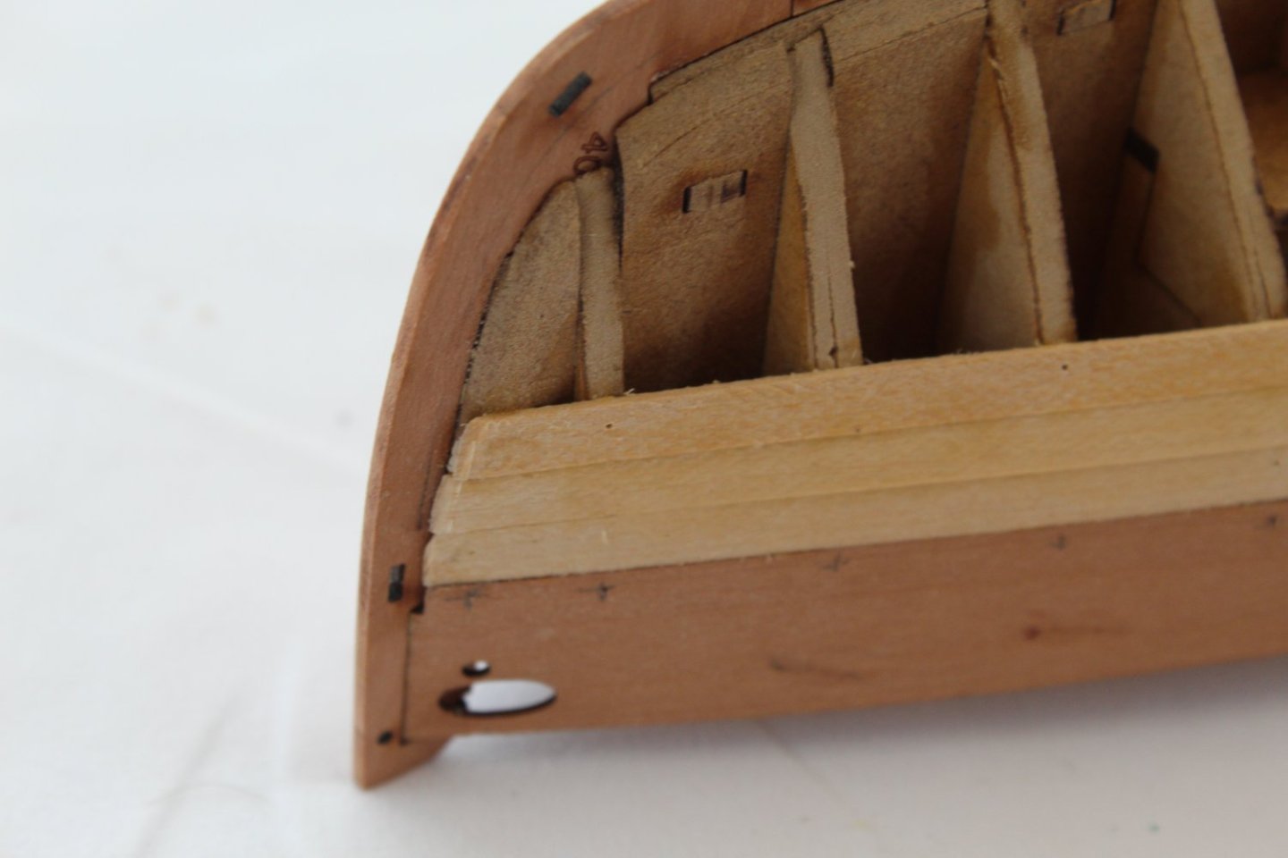
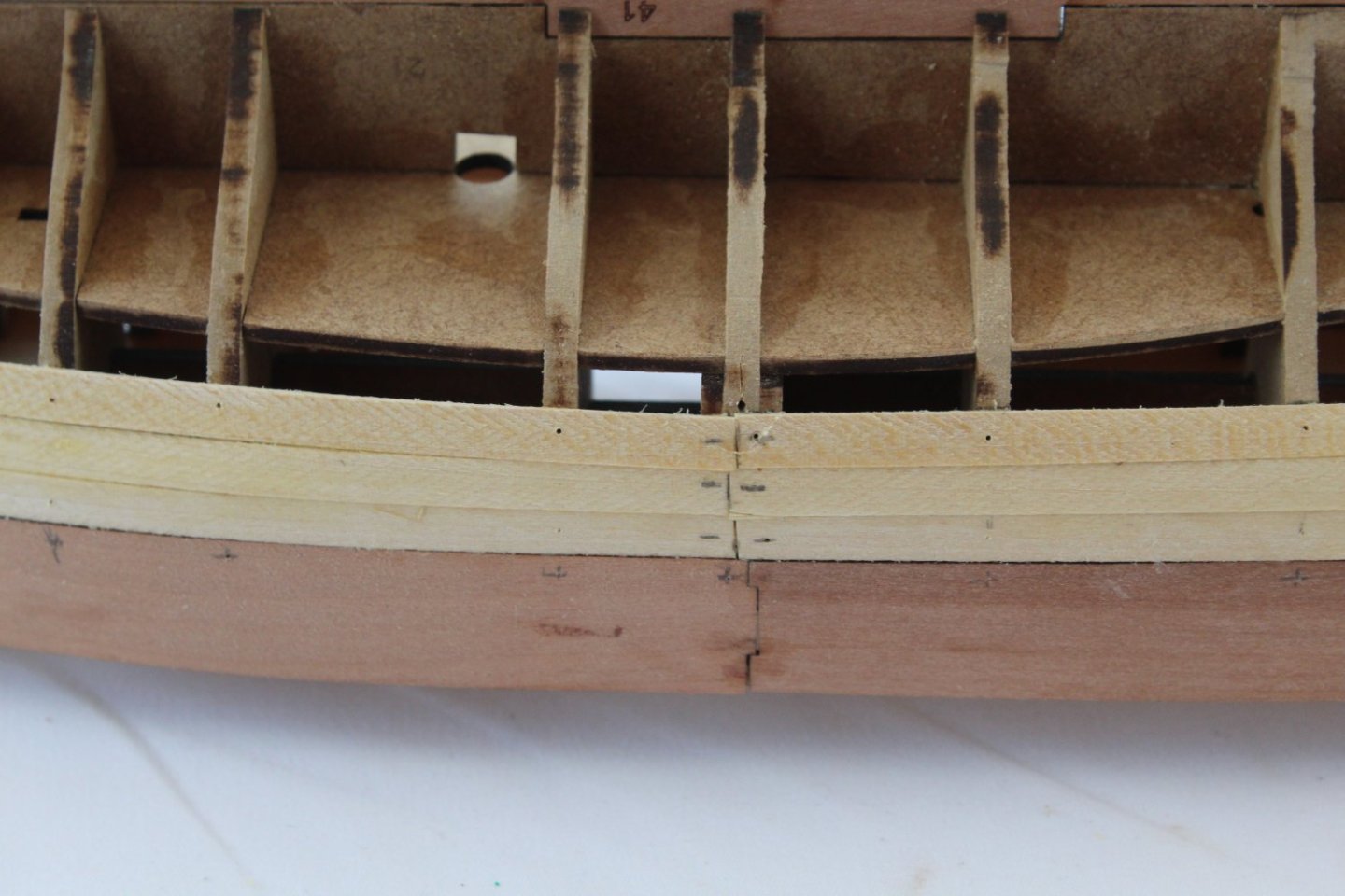
013 - Start of Second Planking Left-Hand Side I have now made a start of the left-hand side second planking. I thought I would share my process in this respect. As can be seen in the first few photos I have added one plank below the outer bulwark pattern, and I have also added the garboard plank to along the keel. I have now fitted the first three planks below the outer bulwark pattern. I did not get the clean joint I was after between the 2nd plank and the counter pattern so it will require a very small amount of filler. I am also preparing the plank that sits next to the garboard plank. As there is a bend at the stern, I soaked the plank for a few minutes in hot water and then clamped the plank to the hull. The plank will be left to dry so the plank can retain the bend before it is glued in place.


- 106 replies
-
- 4
-
-
- Erycina
- Plymouth Trawler
- (and 3 more)
-
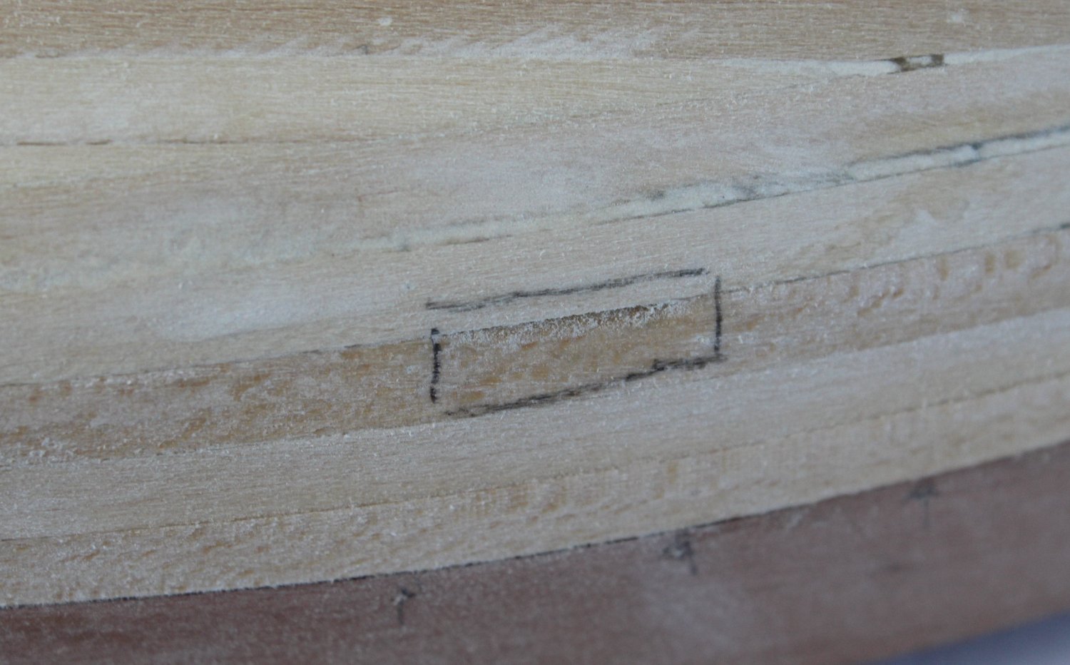
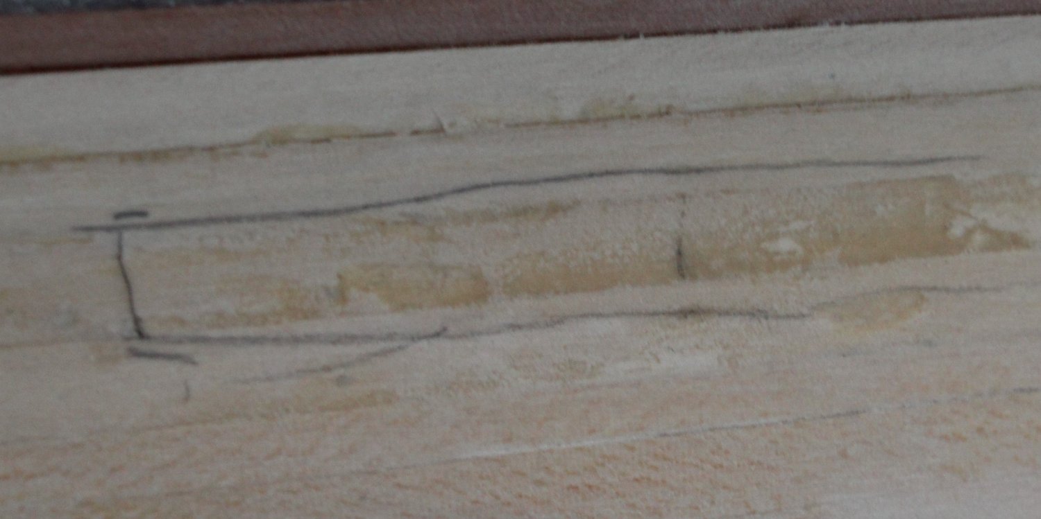
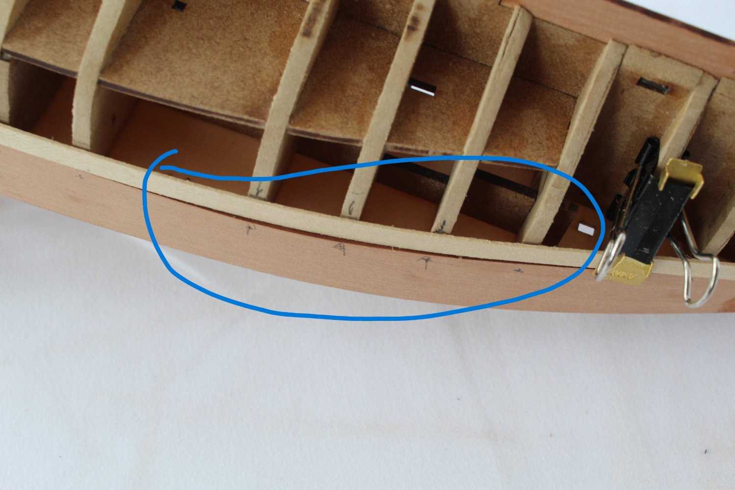
012 - Right-Hand Side Second Planking Completed I have had limited time in the shipyard over the last few days due to some pressing family commitments, so progress on the build has been slow. This afternoon I have managed to complete the 2nd planking on the right-hand side of the hull. I used GA gel to glue the planks to the hull and I am reasonably happy with the end result. I have added some pictures of the planking. Stern area Bow Area I am not sure what I am going to do with the area marked in the next photo, but I am not overly concerned as this area will be painted. I have noted that @James H used a small filler piece on the prototype build which I probably replicate.

- 106 replies
-
- 3
-
-
- Erycina
- Plymouth Trawler
- (and 3 more)
-
Many thanks. I am not sure I have the talent as I made so many mistakes during this build. I have certainly learnt to have patience however.🙂
- 476 replies
-
- 3
-
-
- sphinx
- vanguard models
- (and 1 more)
-
That's what I thought, thanks for the confirmation.
-
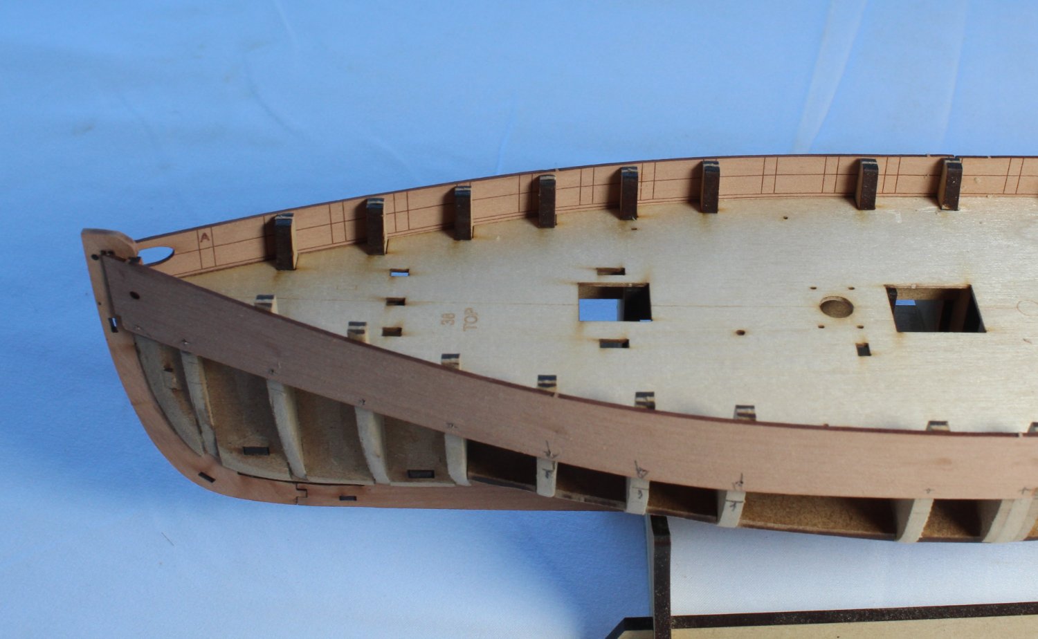
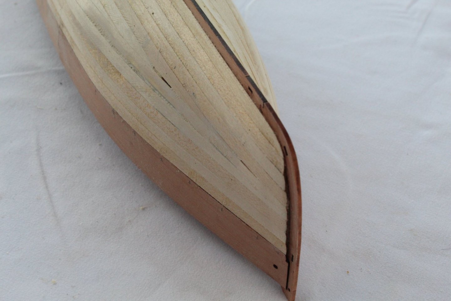
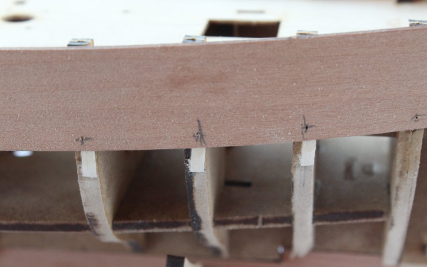
011 - Outer Patterns Fitted I have now fitted all the outer to the patterns (rabbet and bulwarks). I had a slight issue with the left-hand rear bulwark. With it glued in place I noted, when checking the run of the first 2nd planking, that the stern area required a bit more fairing under the bulwark area. Taking great care, I was able to release the outer rear bulwark pattern without damage. With the fairing redone the outer rear bulwark was reglued and looks OK. With regards to the second planking, I was planning to fit full length planks. The photo below shows a test second plank dry fitted to the hull. It looks good with the plank located in the stem post rabbet. However, there is a slight problem with the stern area as the first plank is not quite long enough to be fitted as one plank as can be seen in the photo below. I have two options, as detailed below: Option A - Fit the plank as shown above and to then add a small filler piece to fill the gap. Option B - Fit two planks with a joint at the same point as the front and rear outer bulwarks. I am more inclined toward option A at the moment, but I am open to other suggestions.

- 106 replies
-
- 4
-
-
- Erycina
- Plymouth Trawler
- (and 3 more)
-
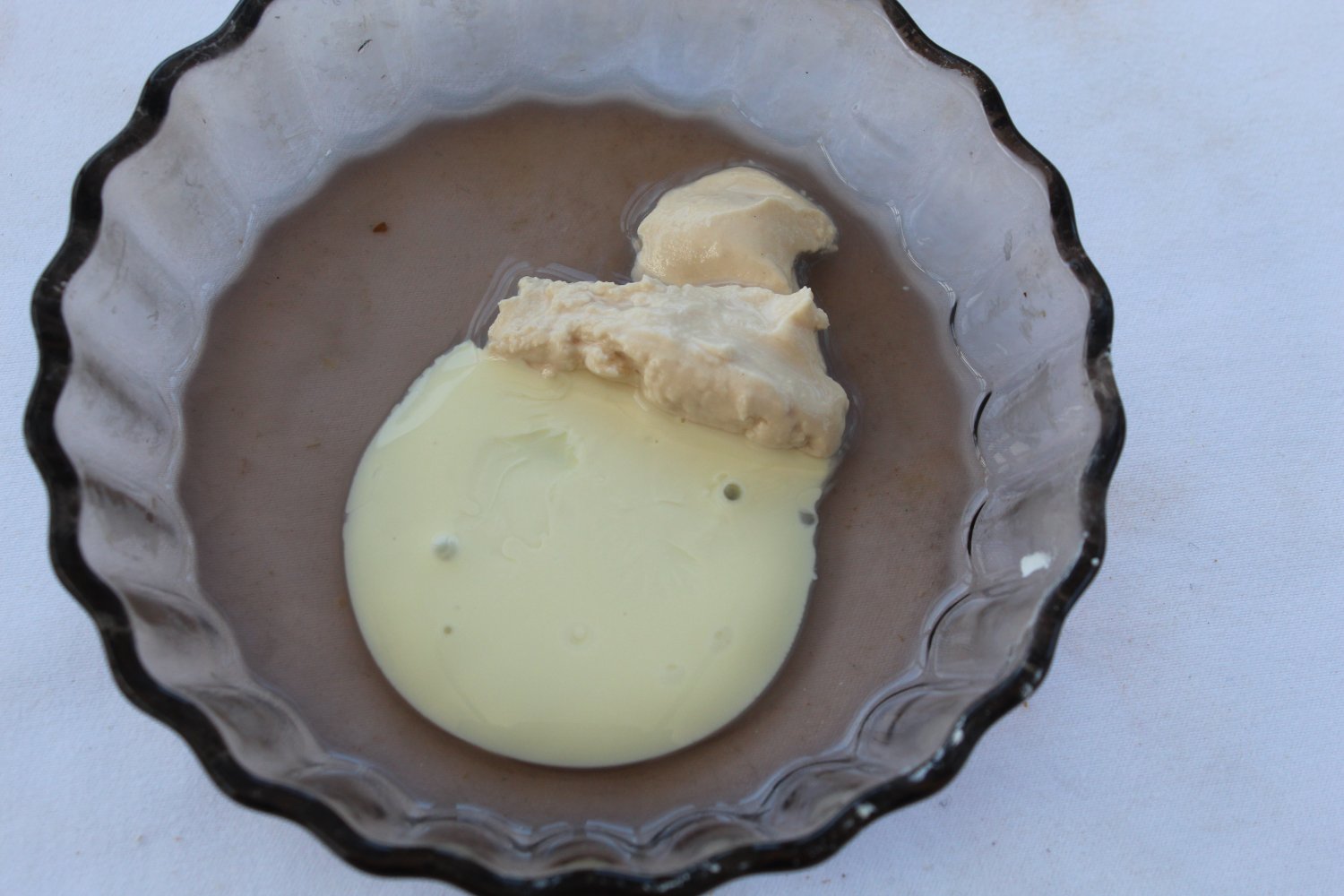
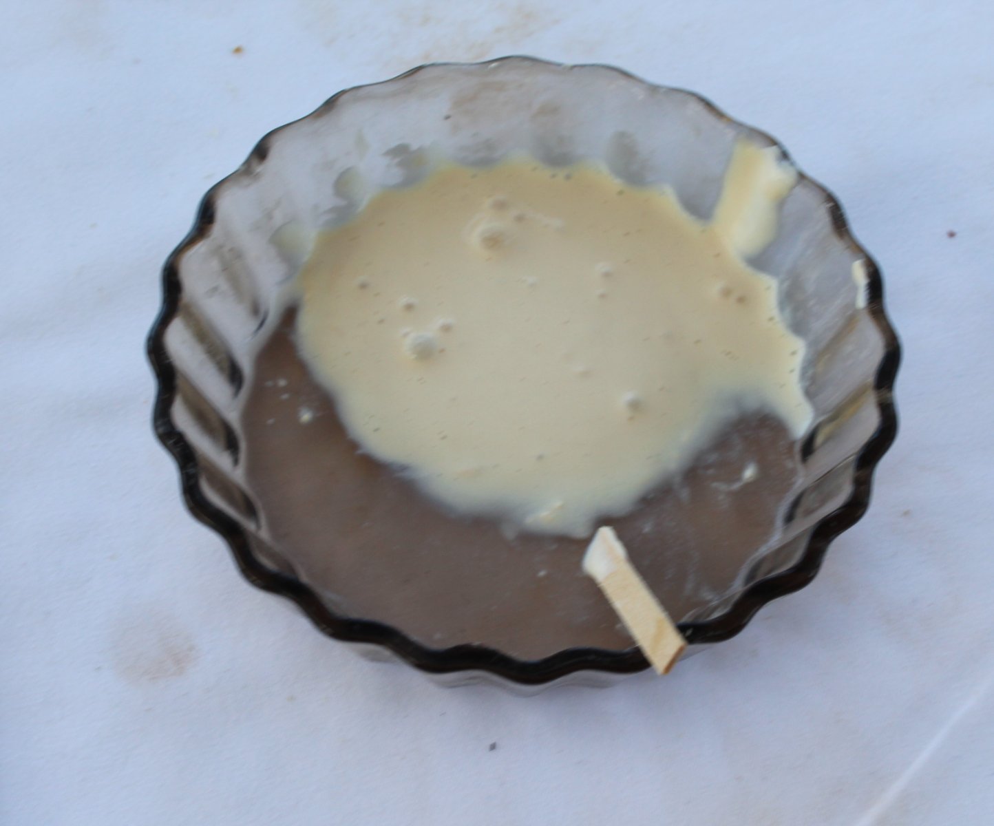
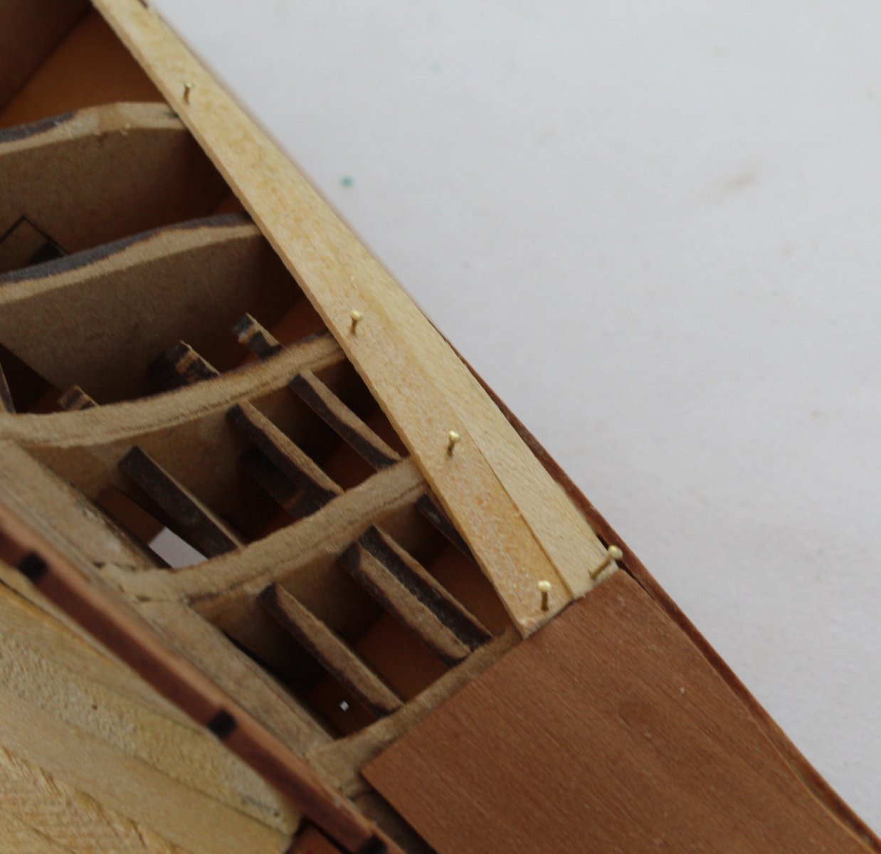
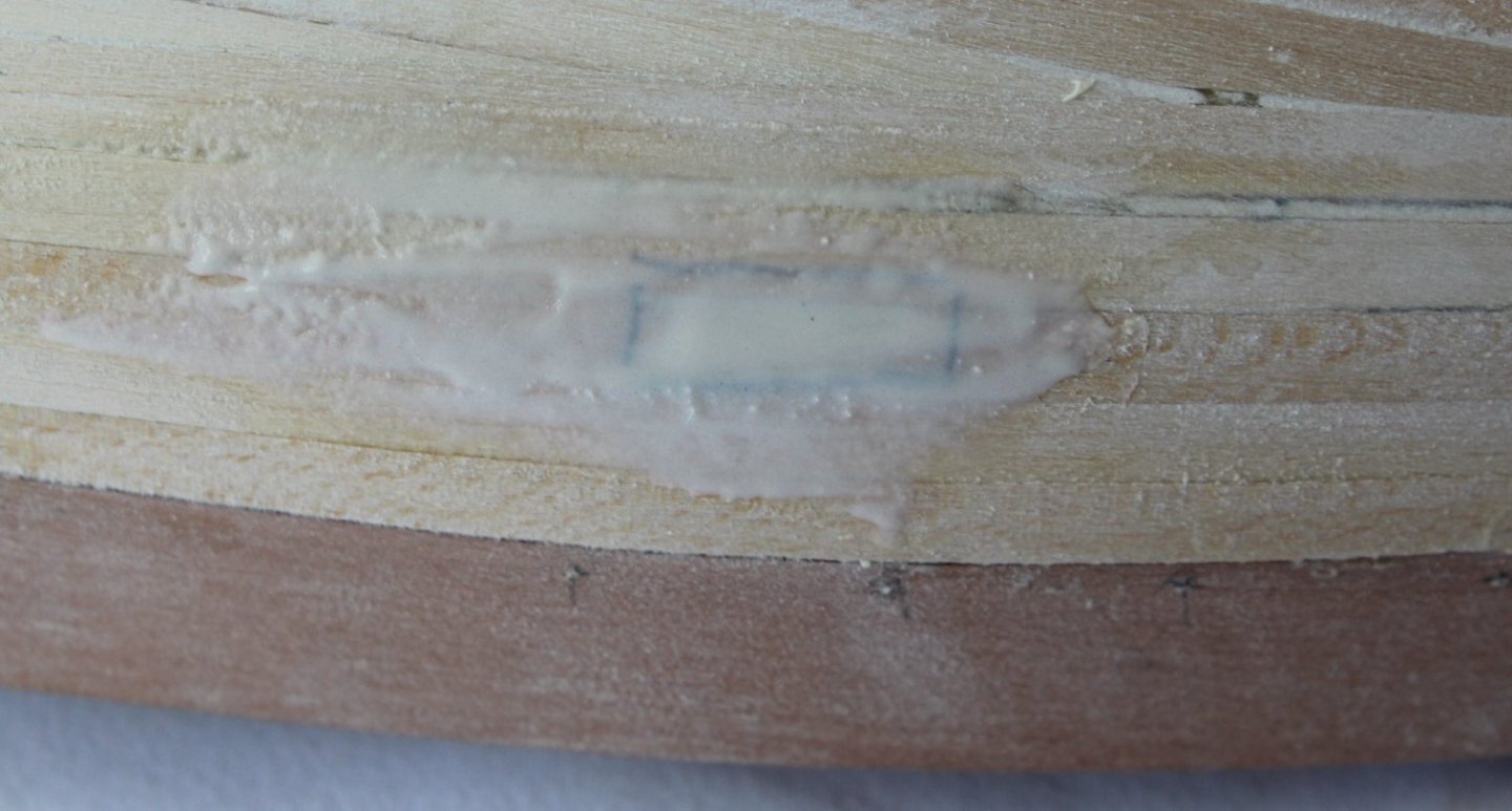
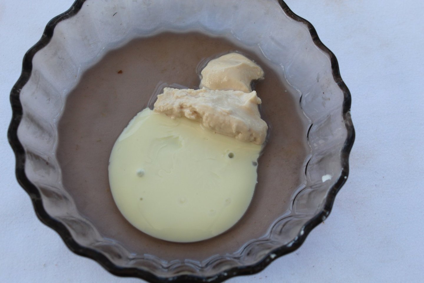
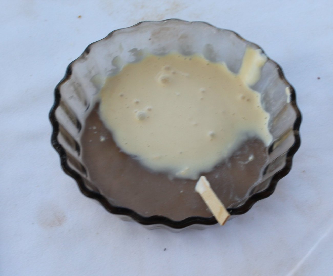
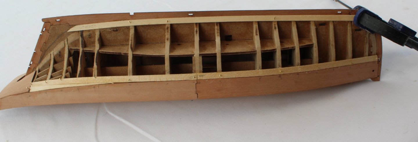
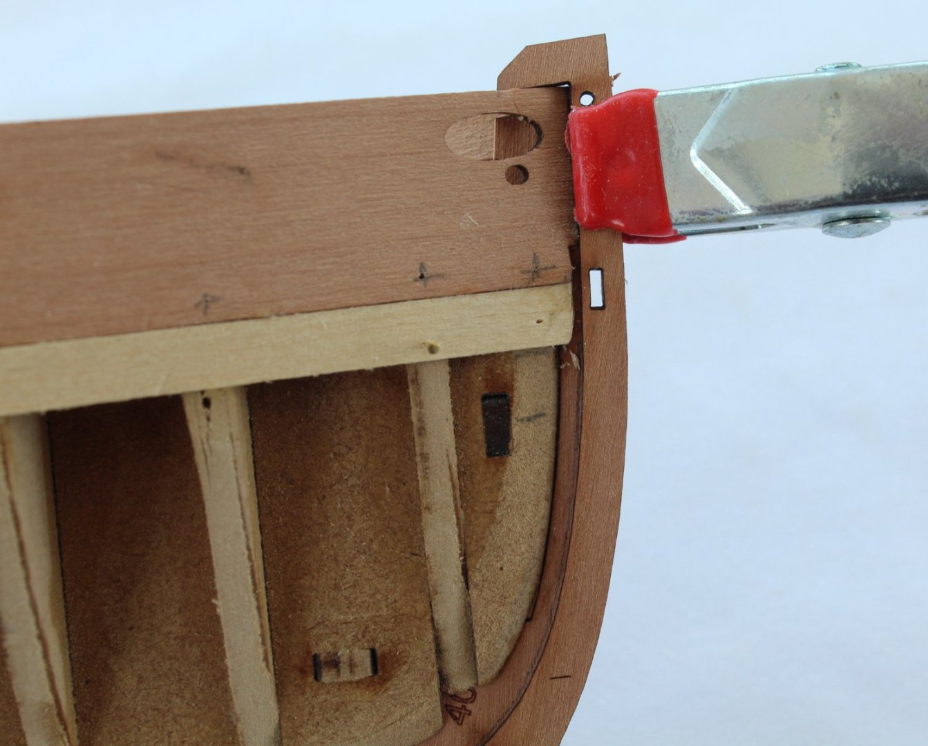
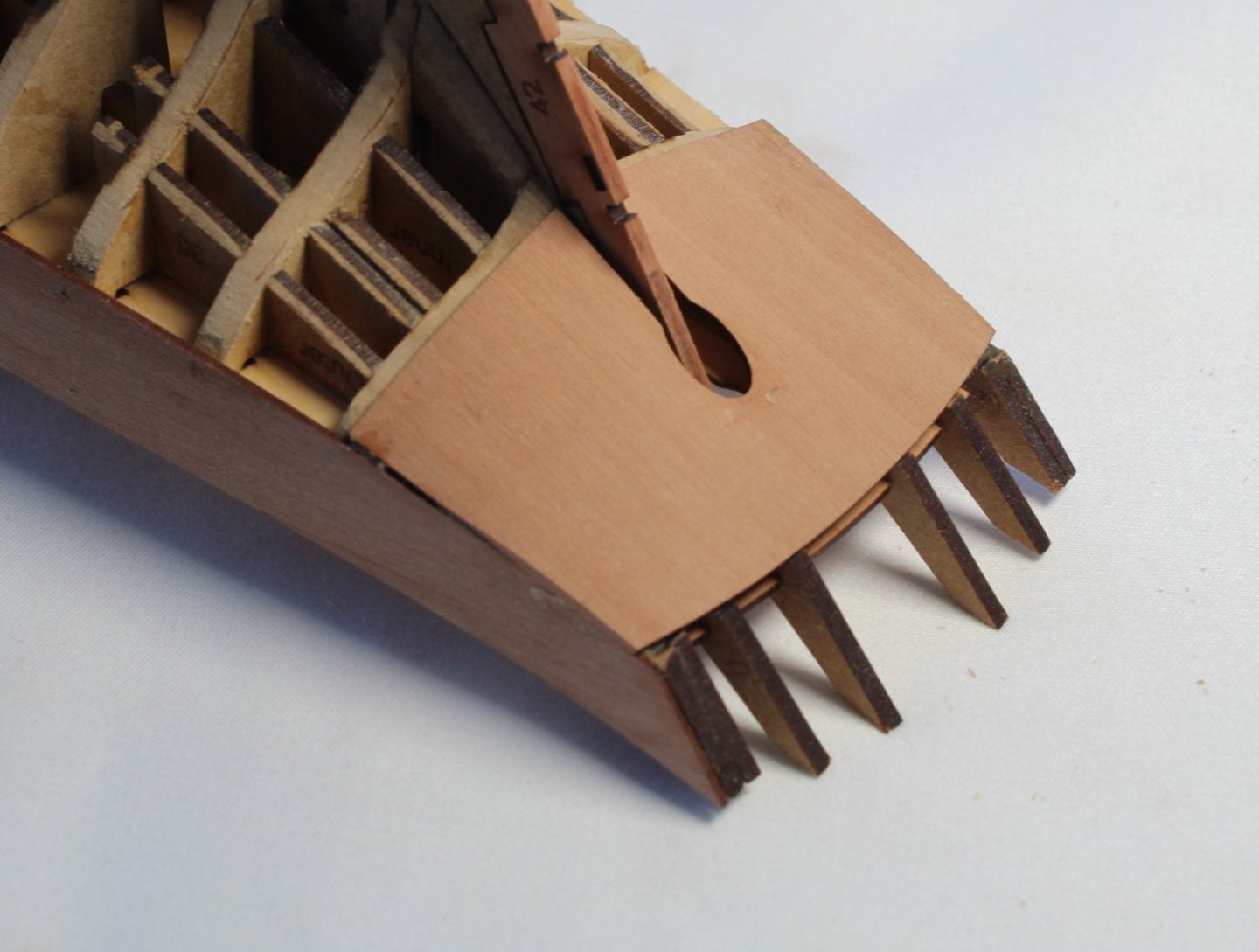
010 - Preparation for 2nd Planking After sanding the hull some more this morning I was happy the hull was smooth except for a couple of areas with dips which needed filling. I used my tried and trusted method for making a suitable filler paste which is a mix of Ronseal multi-purpose natural wood filler, titebond original wood glue and water. I use an approx. 50 / 50 split between the diluted wood filler and titebond. I am unable to take credit for the mixture as @James H described mixing diluted wood filler and titebond in one of his build logs. The photo below shows the ingredients ready to be mixed. Once the ingredients have been mixed, I end up with a nice smooth paste. The filler paste is then pressed into the dip on the hull and is left to dry. Once the filler paste had dried it is ready to sand smooth. The dip has been filled and the hull looks and feels smooth. Now that I am happy with the hull, I decided to dry fit the keel, stem and stern rabbet patterns along with the outer bulwark patterns. The leading edge of both front outer bulwark patterns will need a little bit of sanding to get a good fit with the stem post. After fairing the stern frames, the stern board was glued in place. The outer stern counter pattern had been soaked in hot water for about 20 minutes and was then clamped in place and will be left to fully dry out before I can glue it in place.


- 106 replies
-
- 2
-
-
- Erycina
- Plymouth Trawler
- (and 3 more)
-
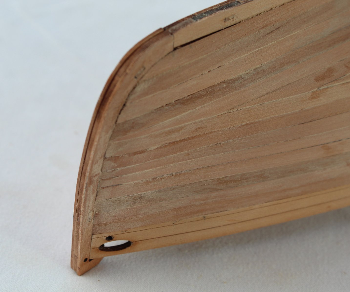
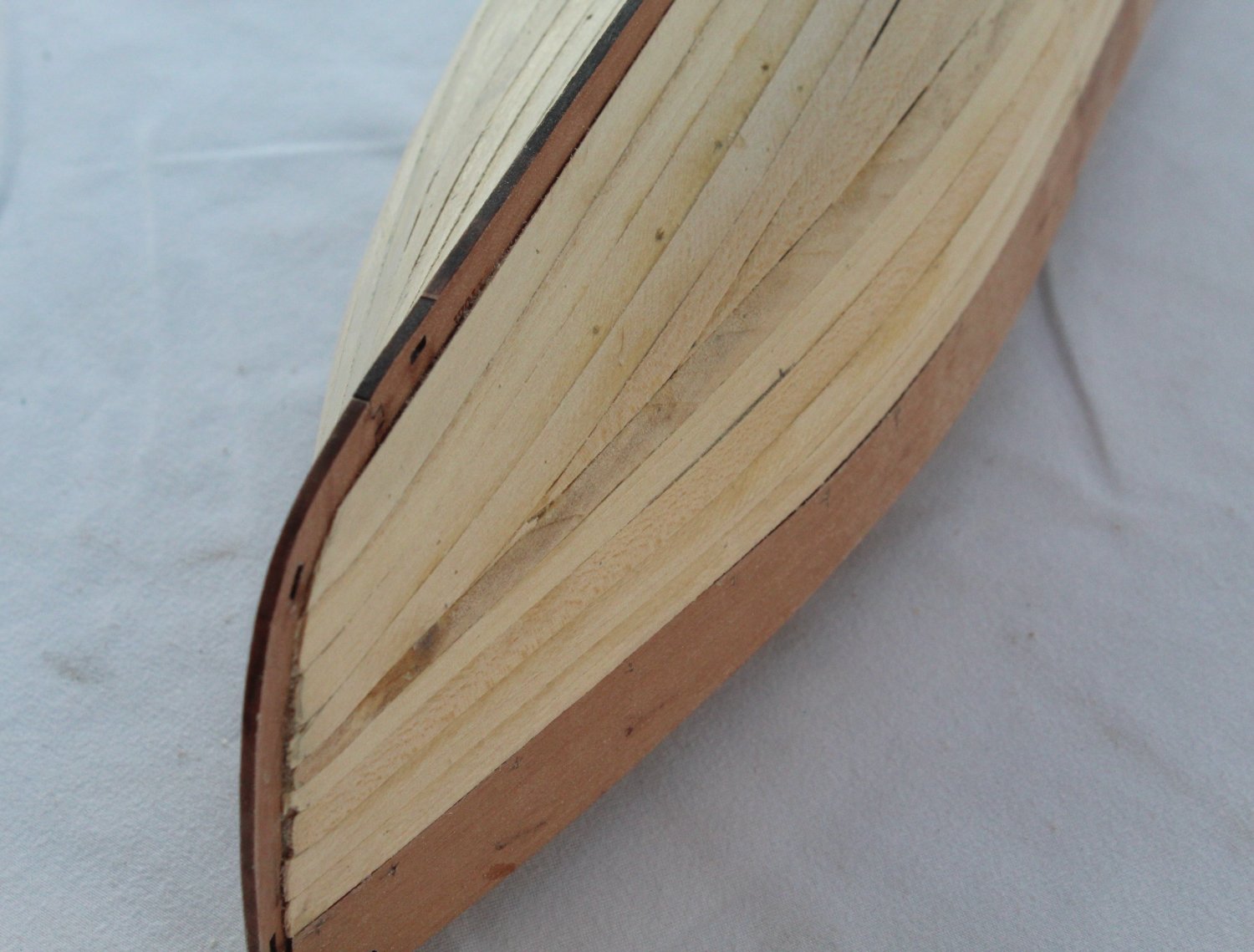
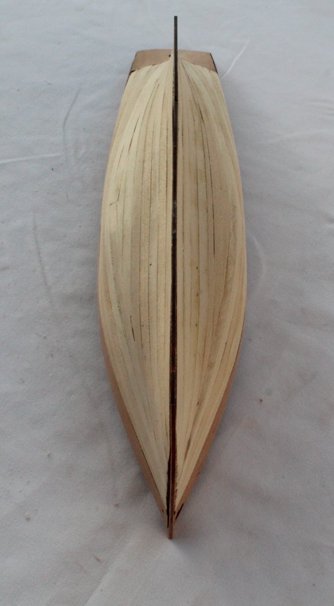
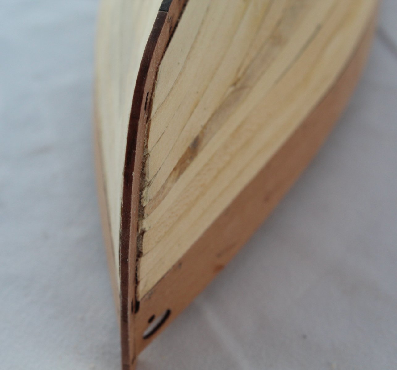
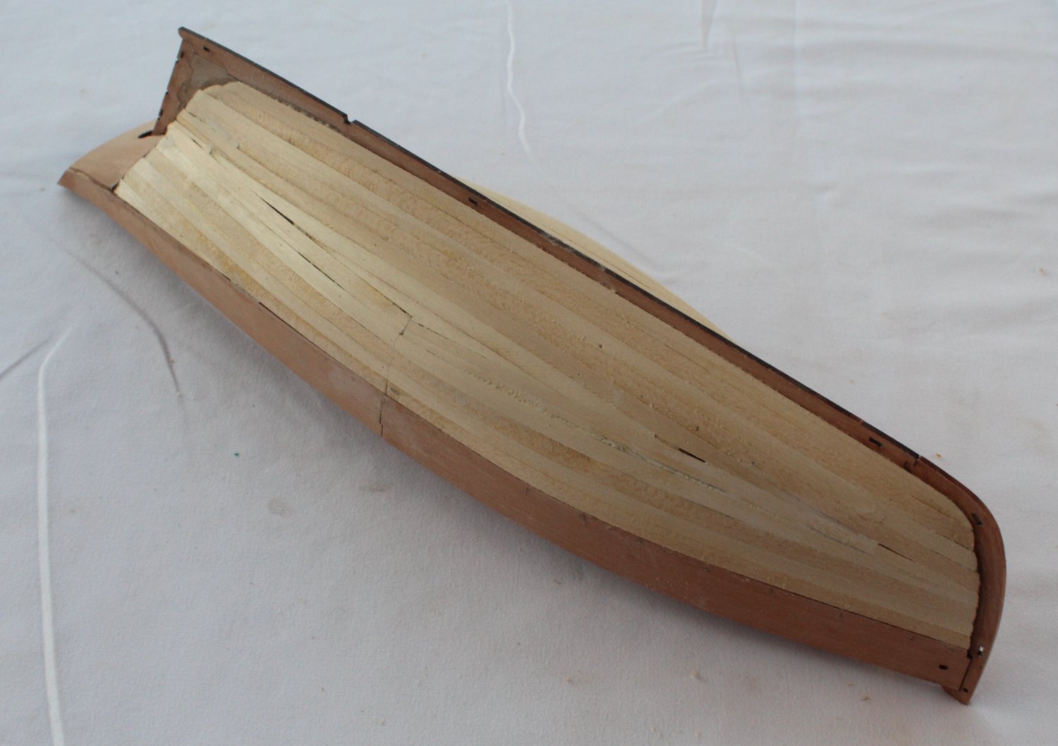
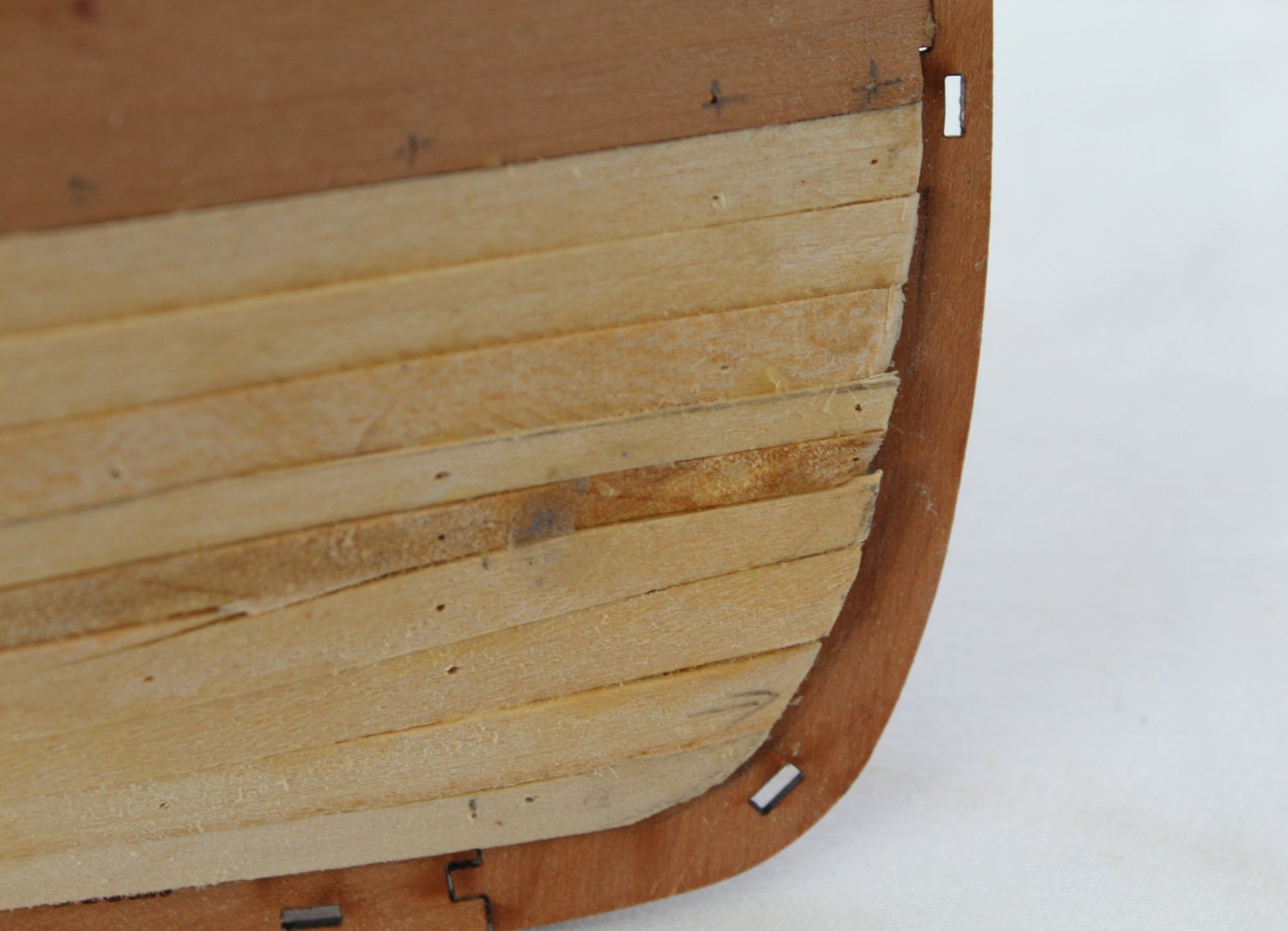
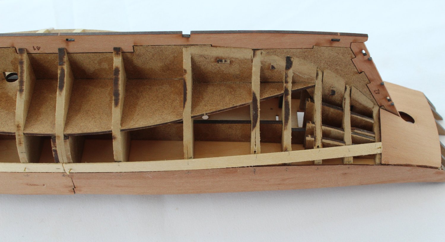
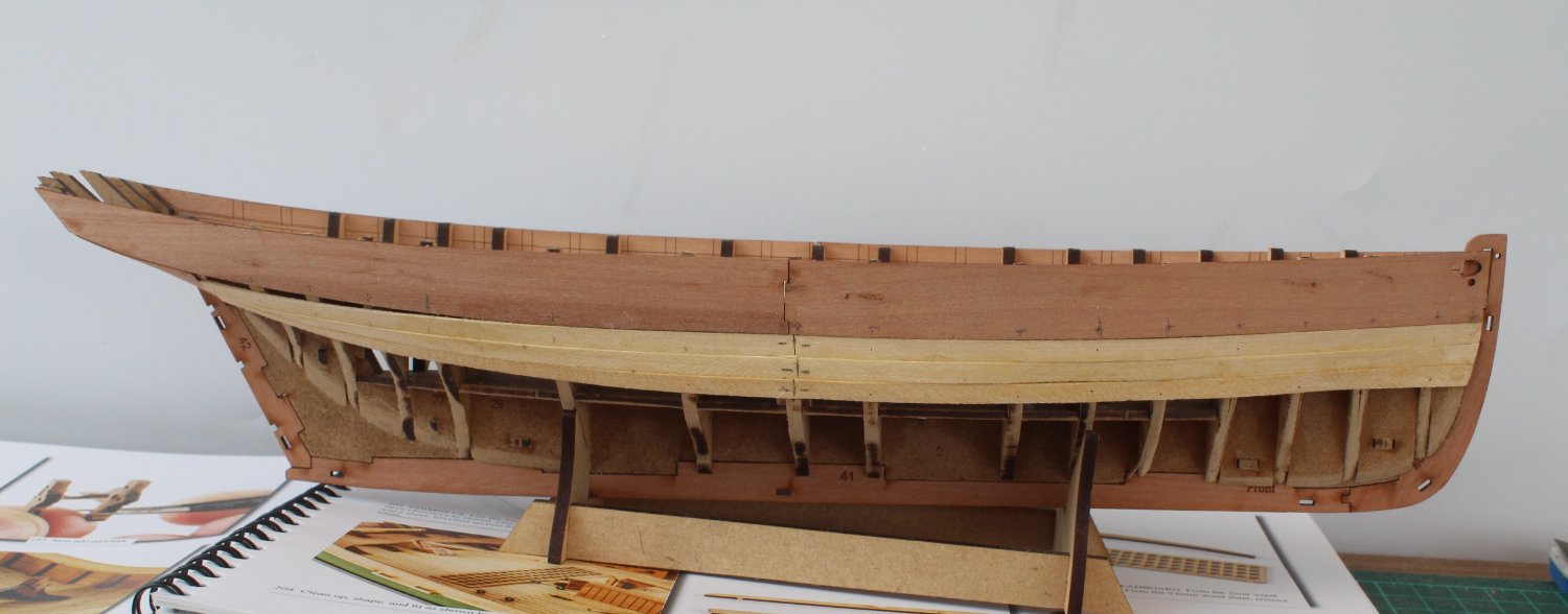
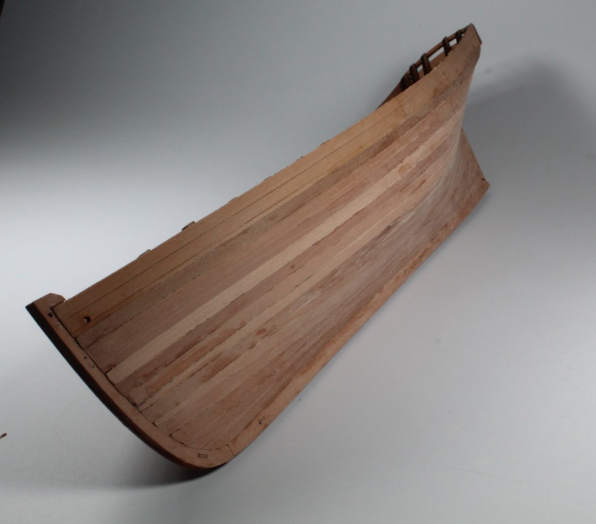
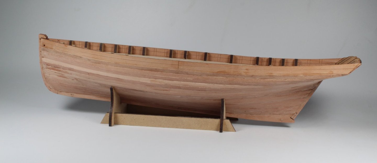
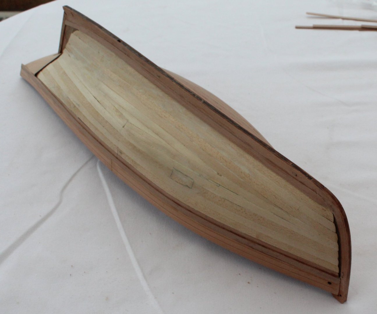
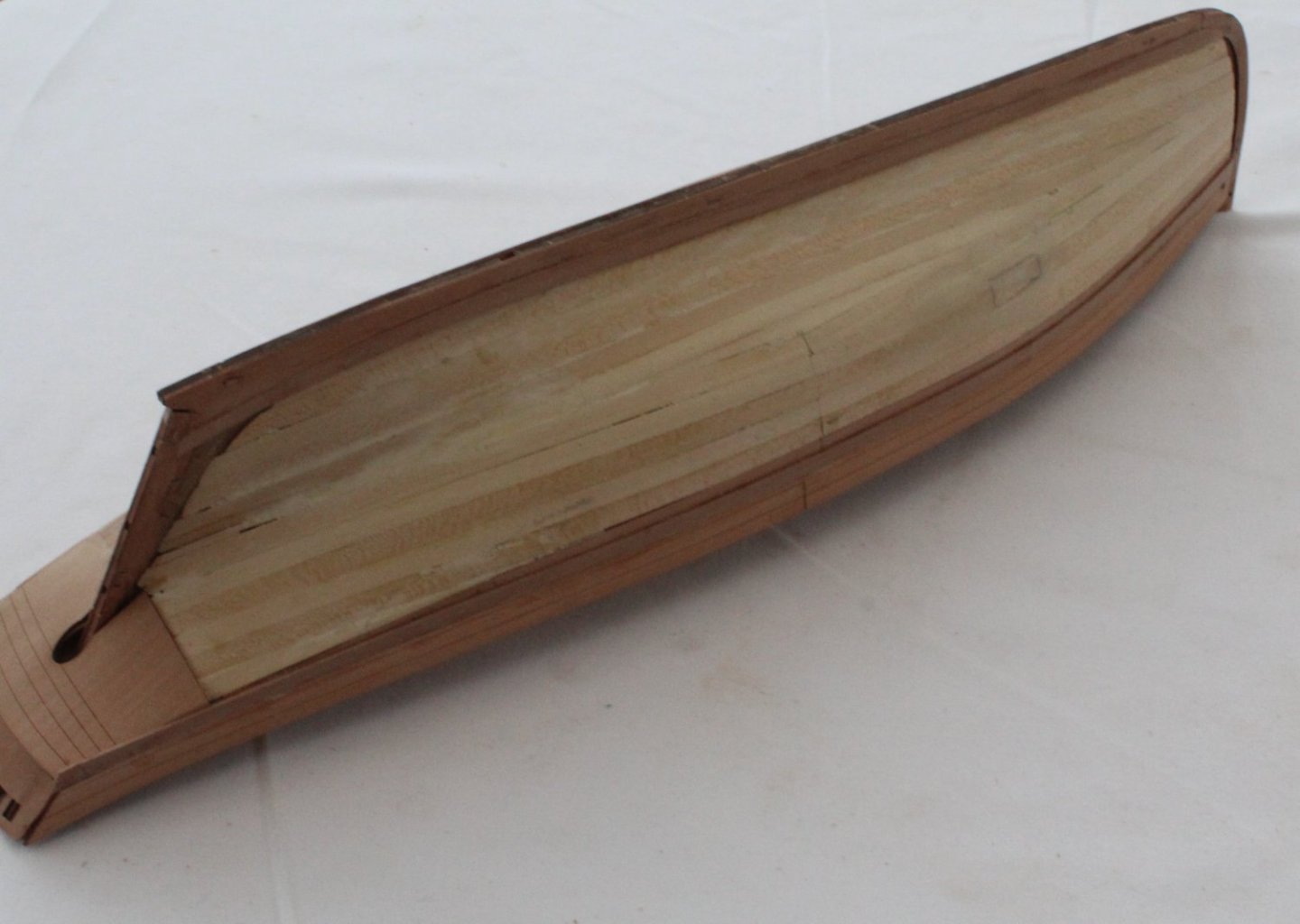
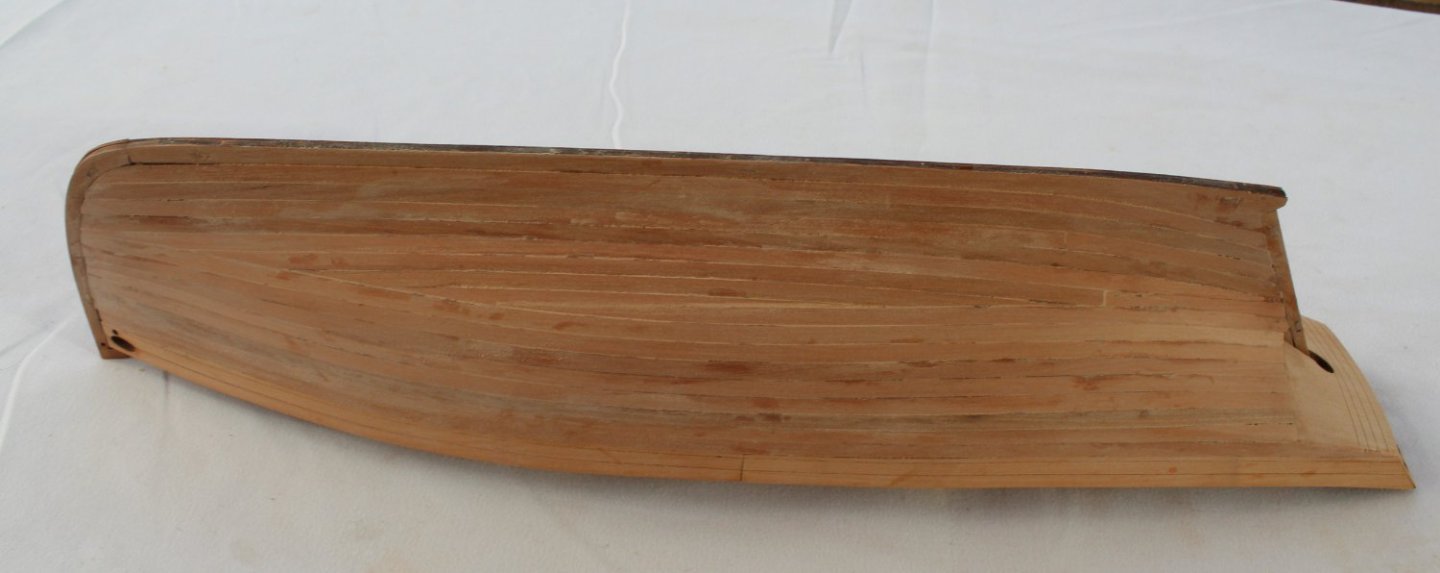
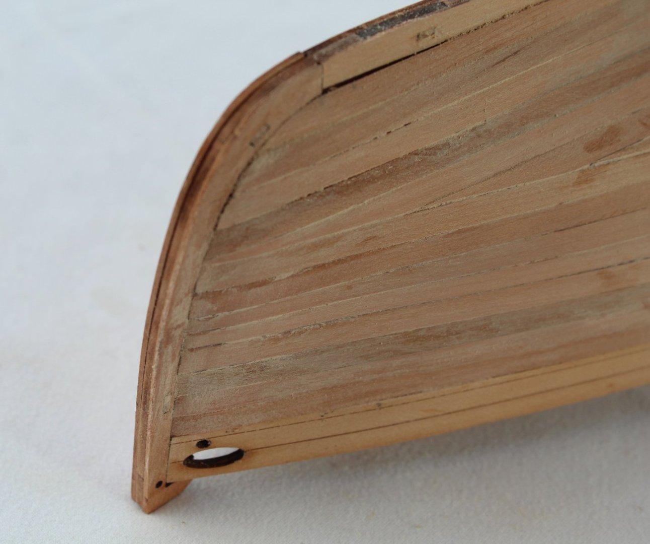
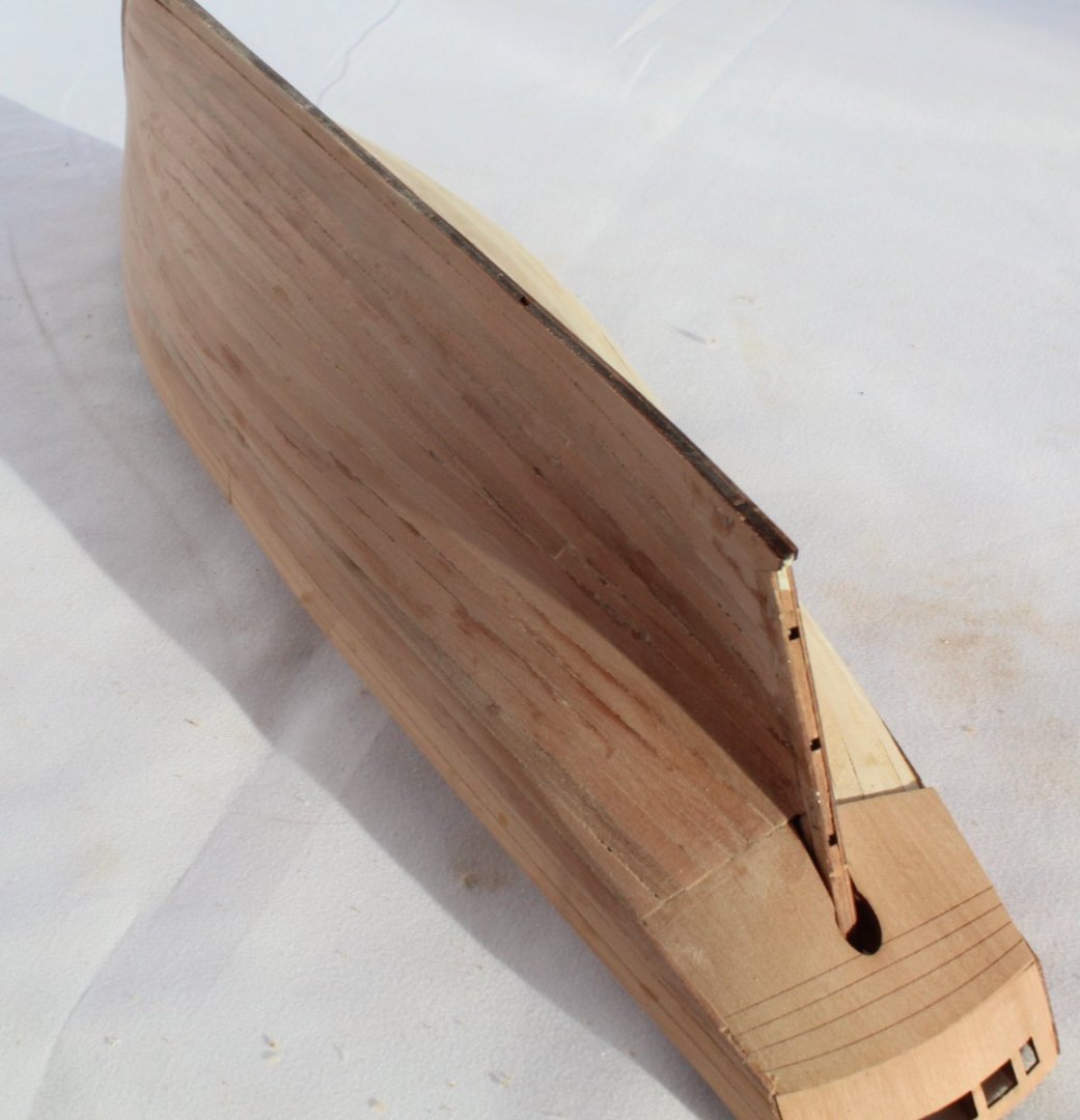
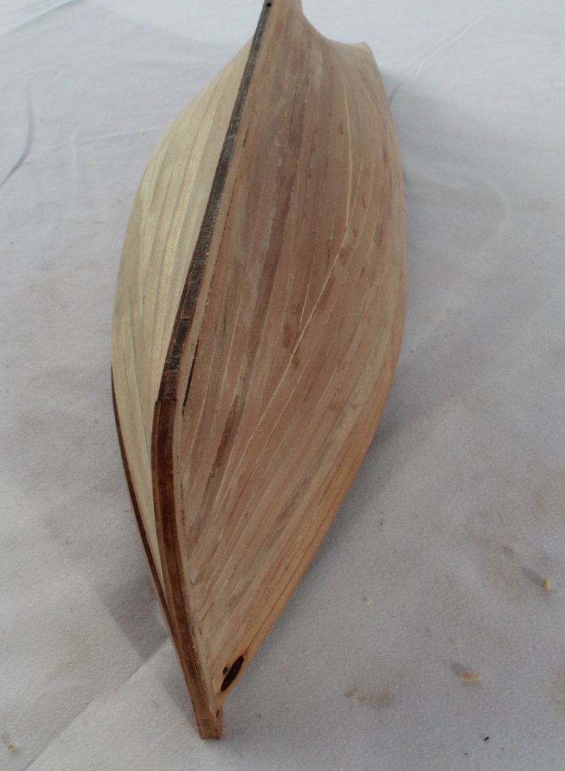
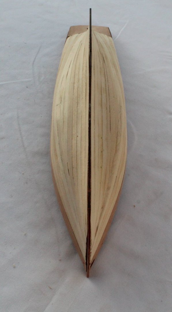
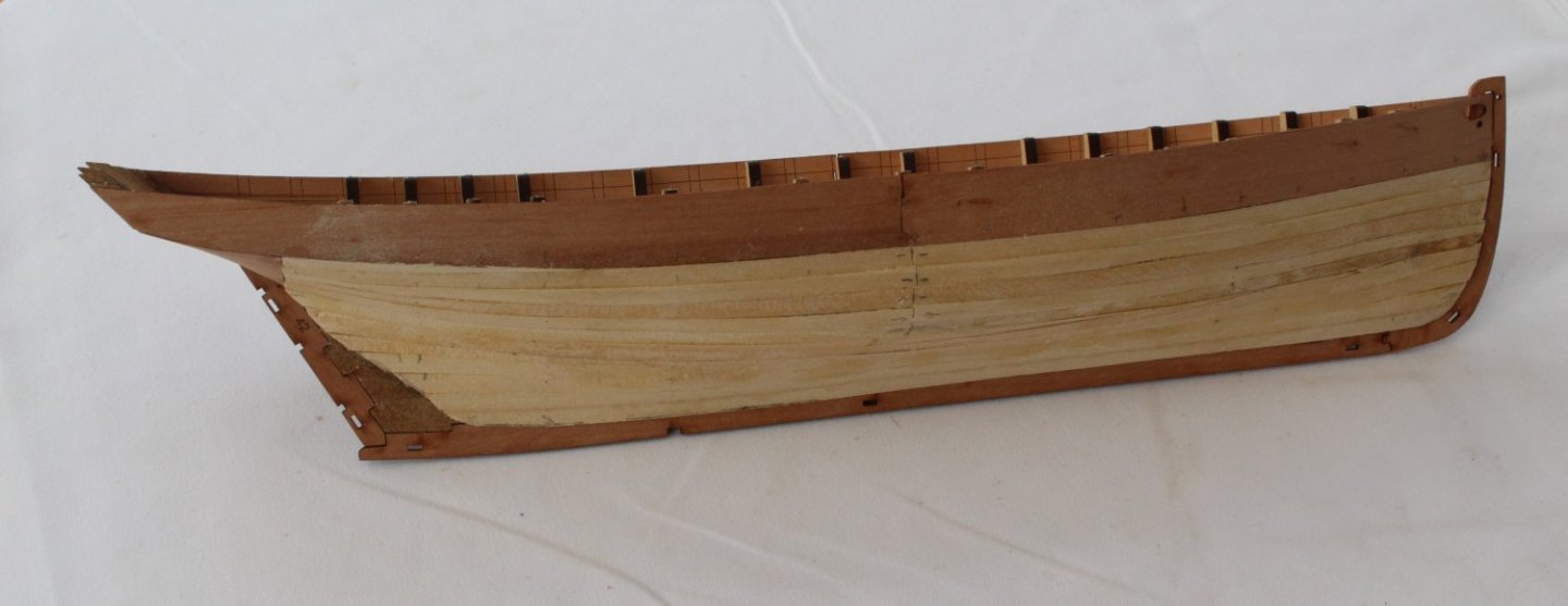
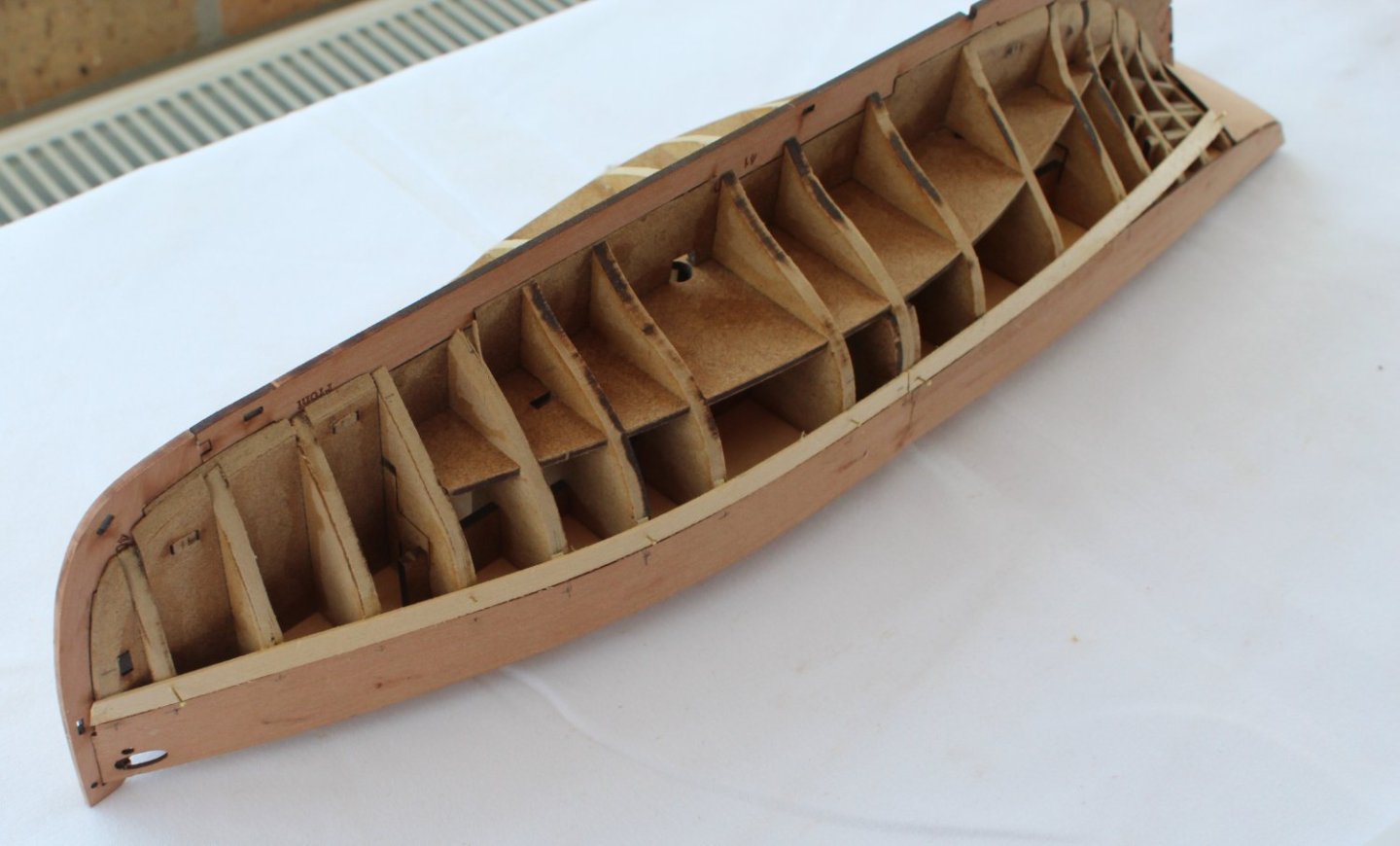
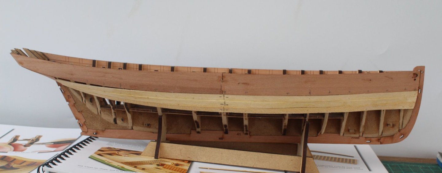
009 - First Planking Completed The first planking of the Erycina hull is now complete. Despite this being my 10th model boat project, I still seem to struggle with mastering the planking techniques. I certainly made a much better job of the right-hand side planking compared with the left-hand side on the Erycina. I have given the hull its first pass of sanding and, for the most part, the hull is now reasonably smooth. I will revisit the state of the hull when I'm next in the shipyard and will continue to sand where appropriate. It is vitally important to get a smooth hull structure before adding the second layer of planking. In no particular order I have attached a selection of photos showing the completed first planking.


- 106 replies
-
- 5
-
-
- Erycina
- Plymouth Trawler
- (and 3 more)
-
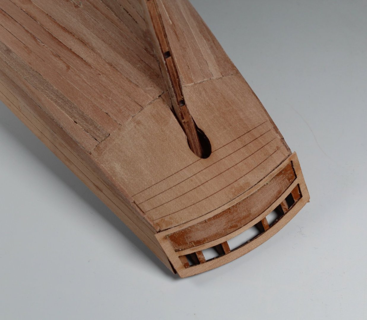
008 - First Planking WIP I have now completed planking the right-hand side of the Erycina hull. The planks went on without too many issues. The first three planks did not require any tapering around the bow area. Once I had completed the first 5 planks, I moved on to add the garboard plank and I then continued to plank upward. There are a few little bumps and dips, but I don't think it will require a great deal of sanding or filling to get a nice smooth surface ready for the second planking. The stern area turned out reasonably neat. The bow area also looks OK. I have now started to plank the left-hand side. I have added the first top plank and the bottom garboard plank. I would expect to complete planking this side in the next couple of days. I have also added the small stern filler piece above the top plank.


- 106 replies
-
- 4
-
-
- Erycina
- Plymouth Trawler
- (and 3 more)
-
Slow and steady but I'm making good progress
-
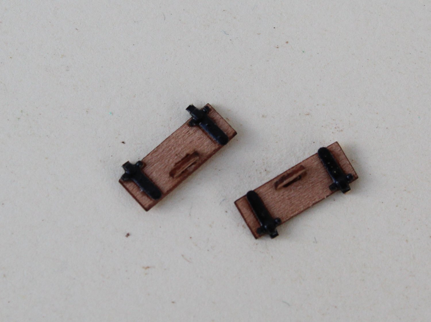
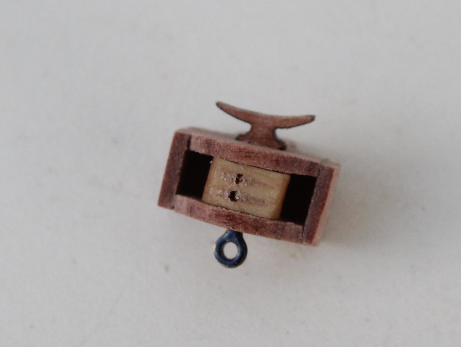
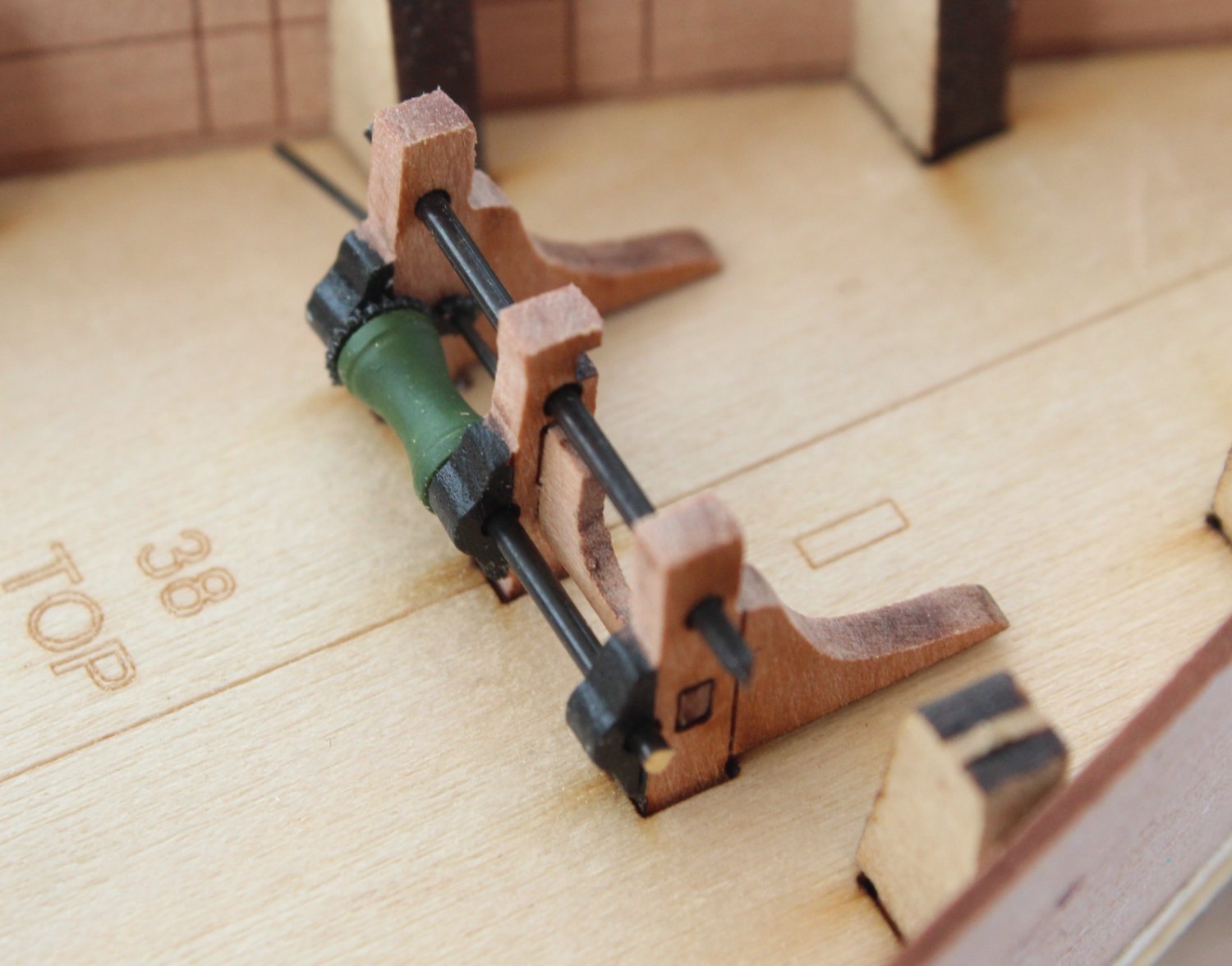
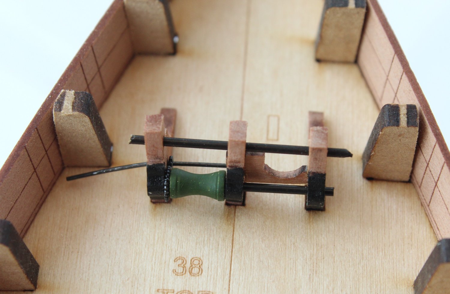
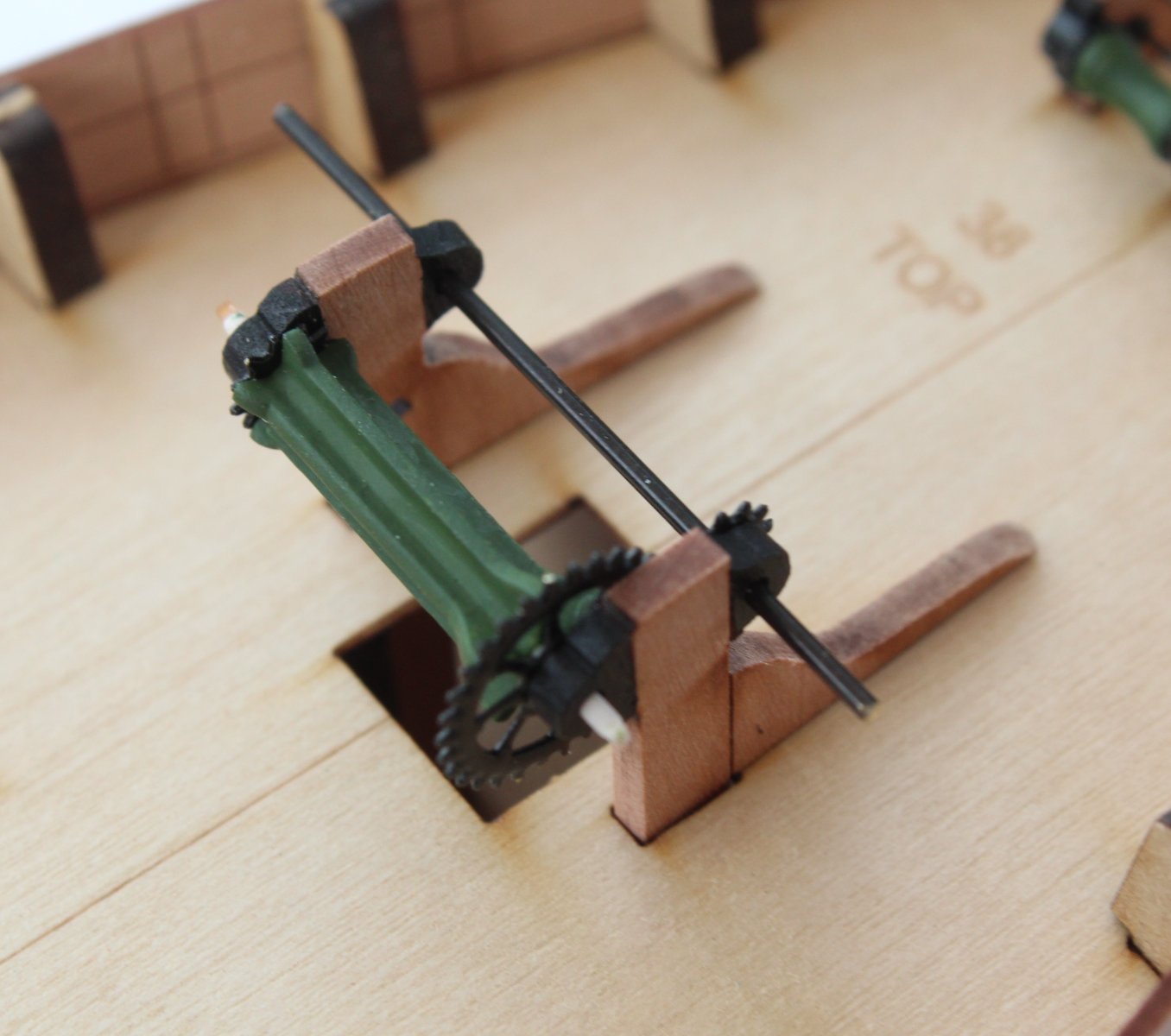
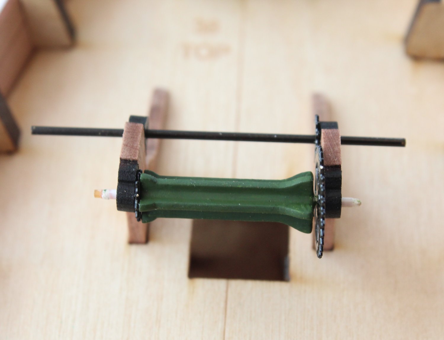
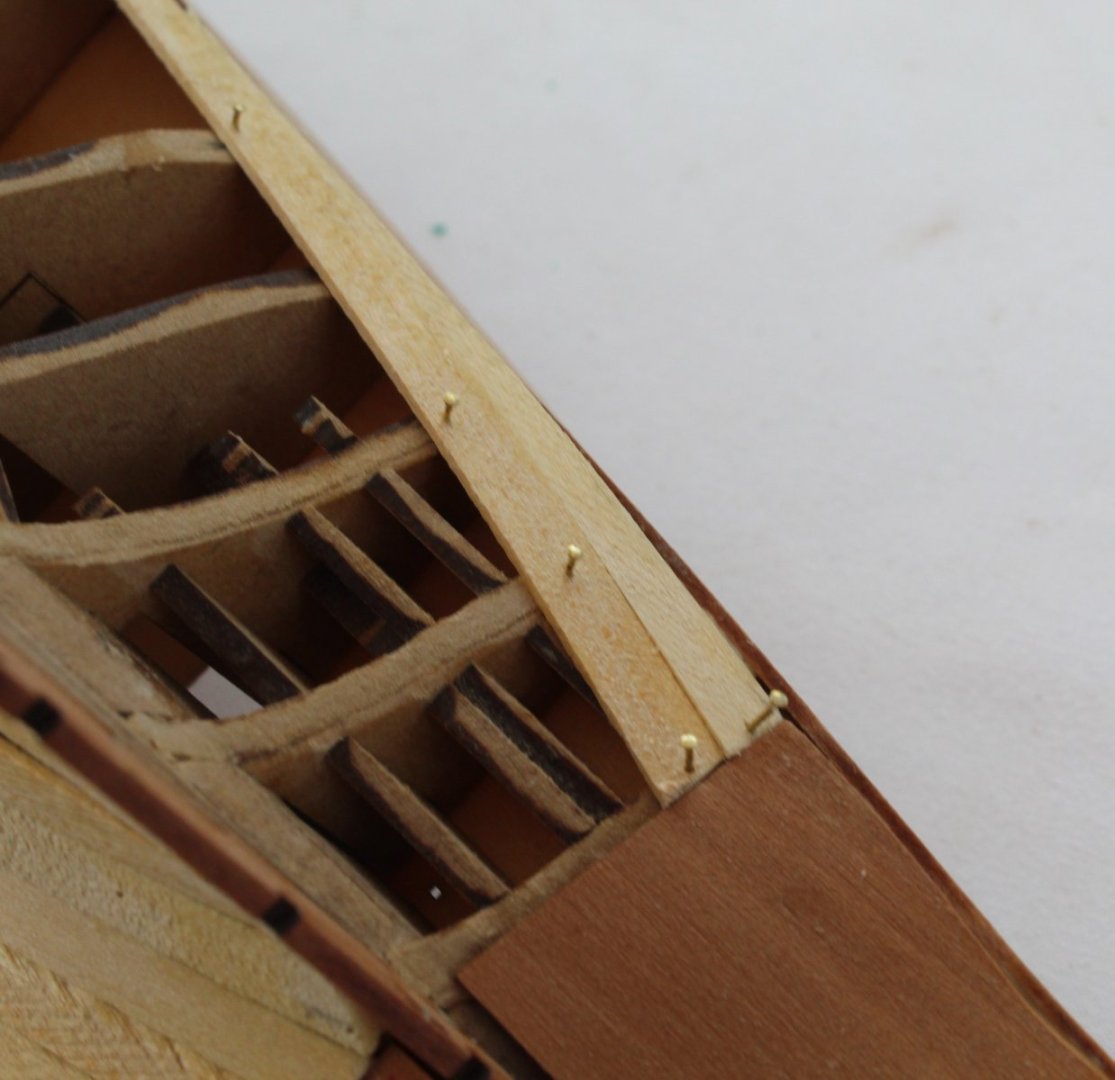
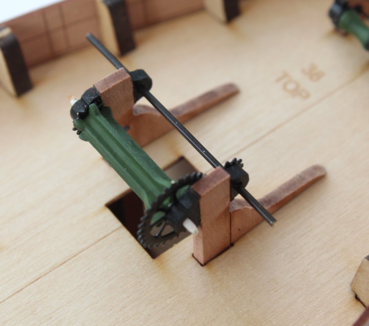
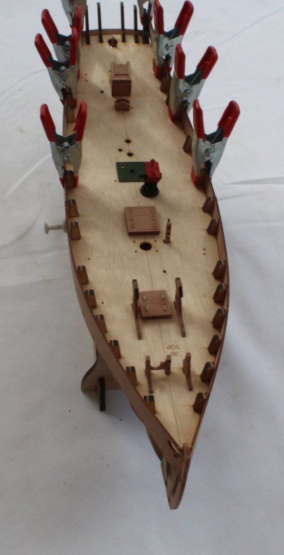
007 - Deck Items and Start of First Planking I have done a bit more work with the deck items now that all the PE parts have been painted. The photo below shows the companionway doors with hinges and handles fitted I have now added the double block and PE parts to the Main Sheet Housing as shown below. The parts have been added to the Gypsy Winch. I have only dry fitted the three brass wire parts as they still need to be cut to the right length. I have test fitted the which to the deck as shown in the next two photos. The parts have been added to the Main Windlass. I have only dry fitted the brass wires as they still need to be cut to the right length. I have test fitted the windlass to the deck as shown in the next two photos. As indicated in a previous post I noted that I would need to add some shims to the bulkheads before I could start the planking which I have now done, as can be seen in the photo below. When starting to add the first plank to the stern area I felt it was better to let the plank following a natural path which meant I will need to add a steeler to fill the gap. The first plank has been fitted. I did dry fit the stem rabbet pattern and drew a pencil line which will aid me when planking to the stem post. When fitting the planks, I am beveling the top edge before fitting which does help get a better joint between the planks. I have been taking my time adding the planks and I have completed three planks.


- 106 replies
-
- 5
-
-
- Erycina
- Plymouth Trawler
- (and 3 more)
-
An excellent model, you must be immensely proud of your build.
- 857 replies
-
- 5
-
-

-
- Sphinx
- Vanguard Models
- (and 1 more)
-
006 - More Fairing, Planking Issue and Deck Items As @James H pointed out I had not faired the outer stern frames. This has now been done. The bulwarks are still drying after being soaked to remove the residual wood glue, so they are only clamped on the hull in the pictures below. I then decided to check how the first plank would look. For the most part I am really happy with the how this plank will lay. However, I did detect an area where there is a gap as can be seen in the next photo. As there is no gap between the bulwarks and bulkheads this is probably due to me over fairing some of the bulkheads. It is not a major issue as I will just add some filler shims so, when fitted, the plank will be at the same level as the bulwarks. I then thought it would be fun to test fit the some of the deck items. Some of these deck items require some PE parts to be added. The sheet is currently in the paint shop where I am waiting for the black paint (sprayed on) to dry
- 106 replies
-
- 5
-
-
- Erycina
- Plymouth Trawler
- (and 3 more)
-
Great job. I'm looking forward to building this one.
- 59 replies
-
- 1
-
-
- saucy jack
- fishing smack
- (and 2 more)
-
Many thanks James Both rear bulwarks are removed so I can fair the outer stern frames as they should be done. Glenn
-
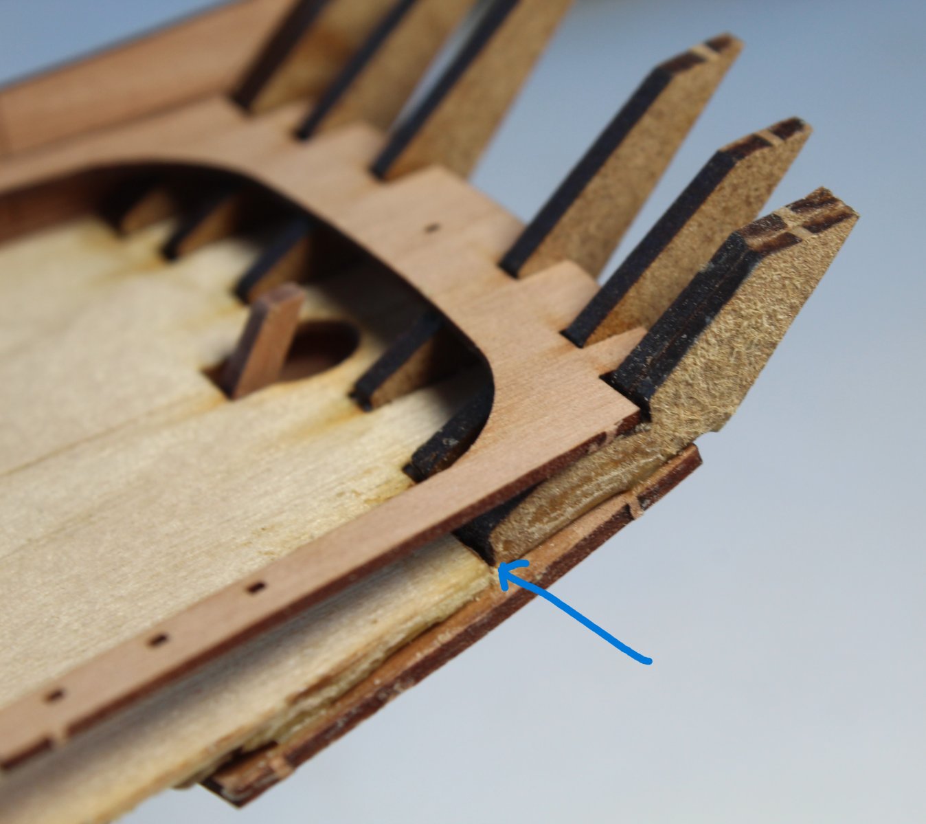
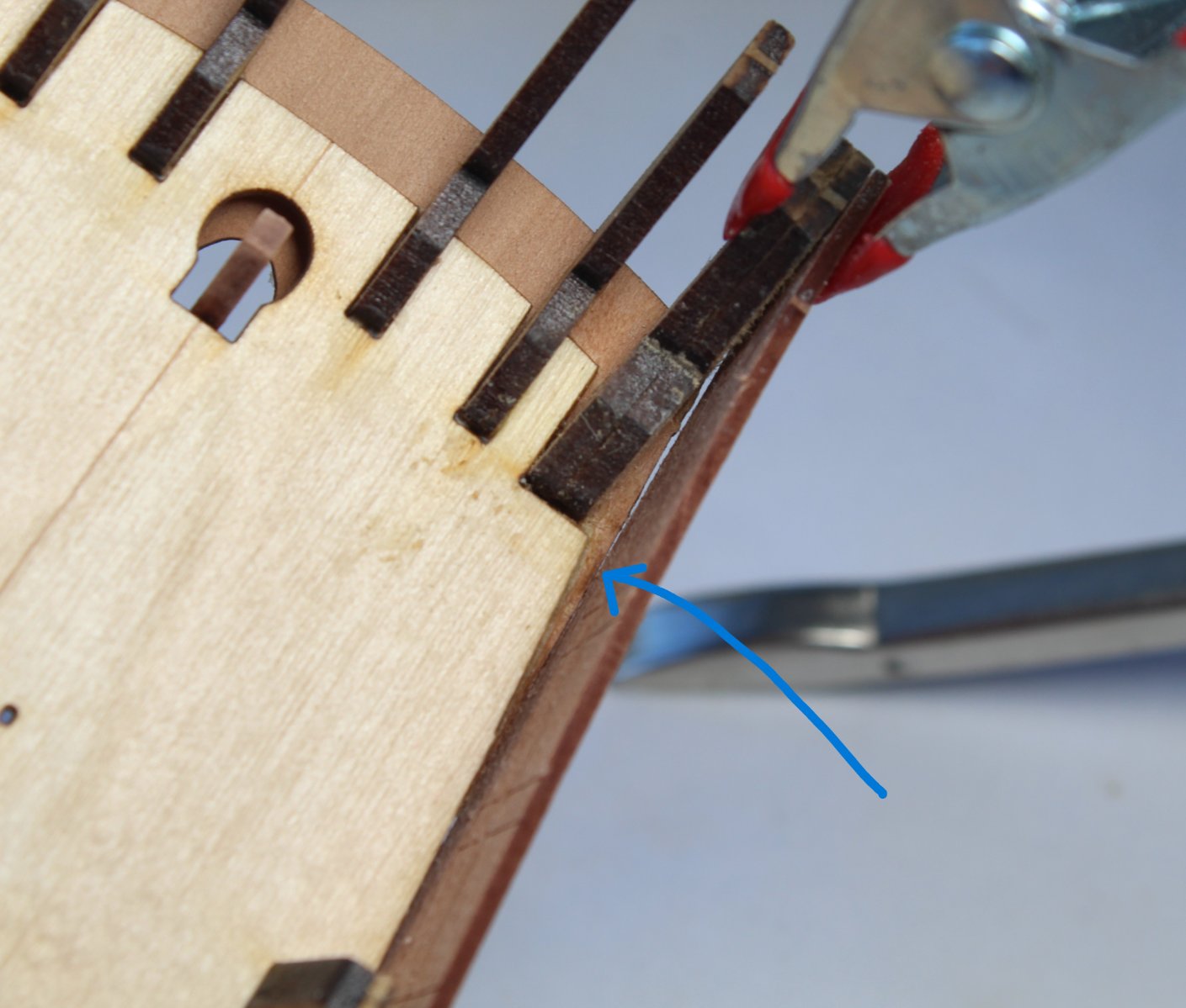
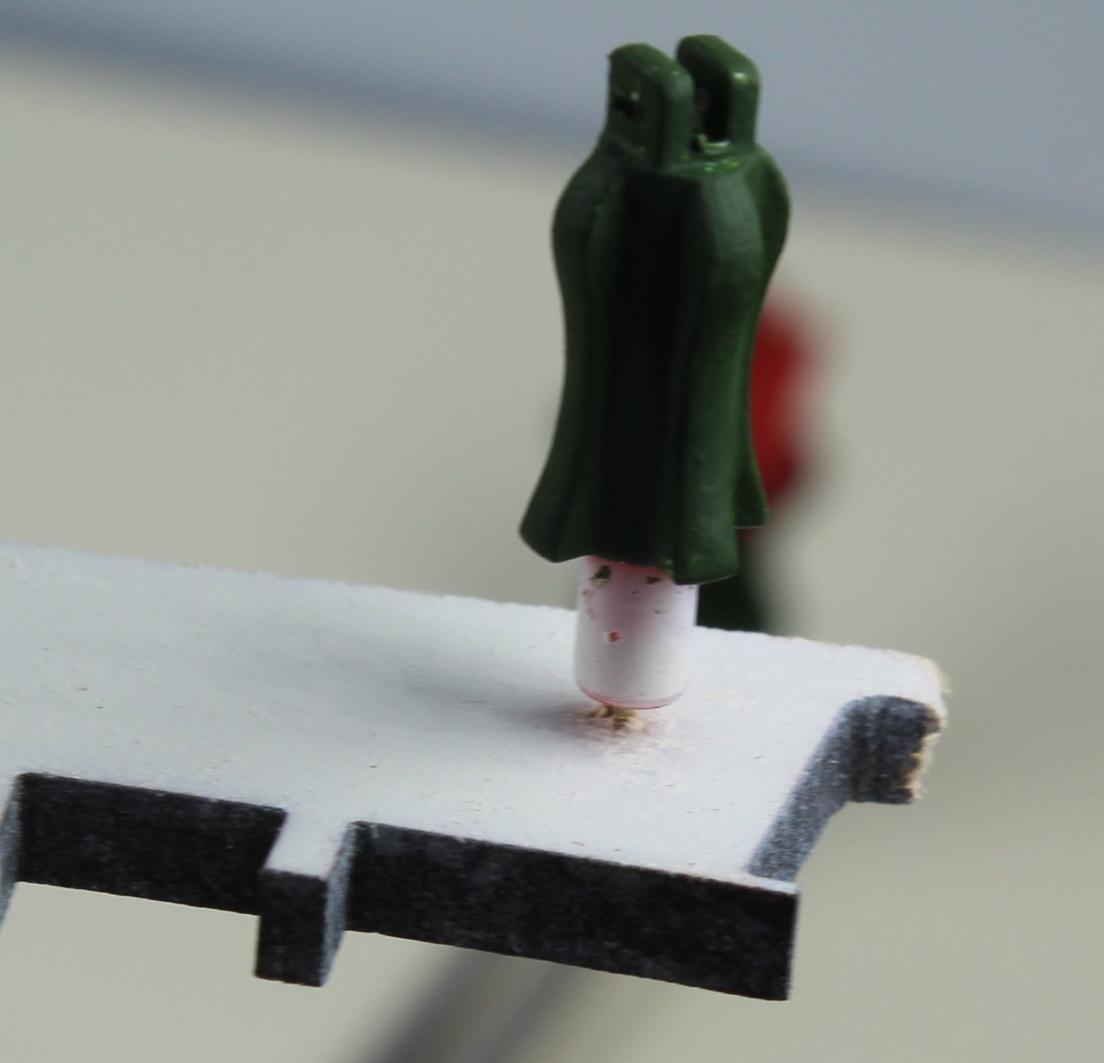
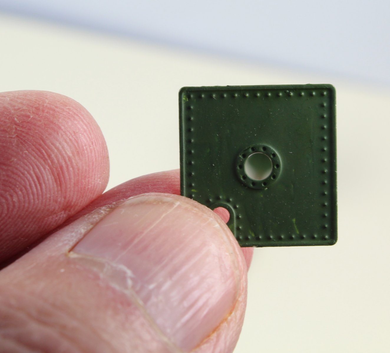
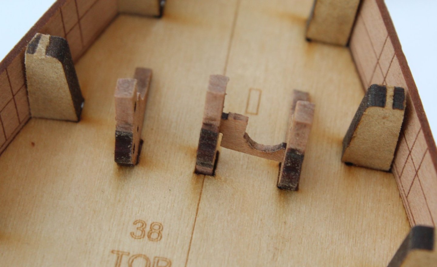
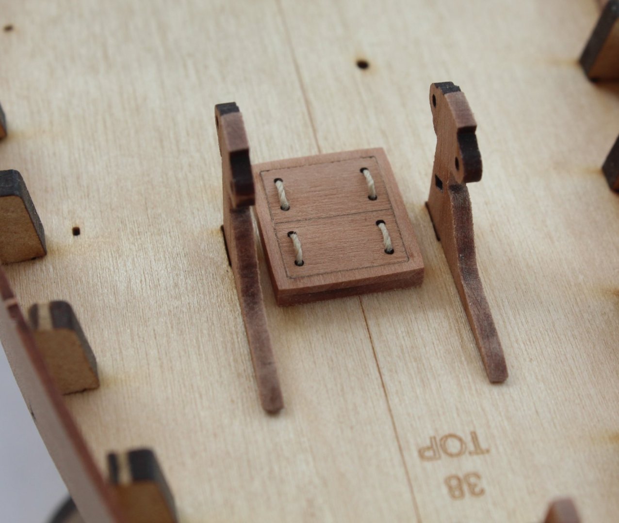
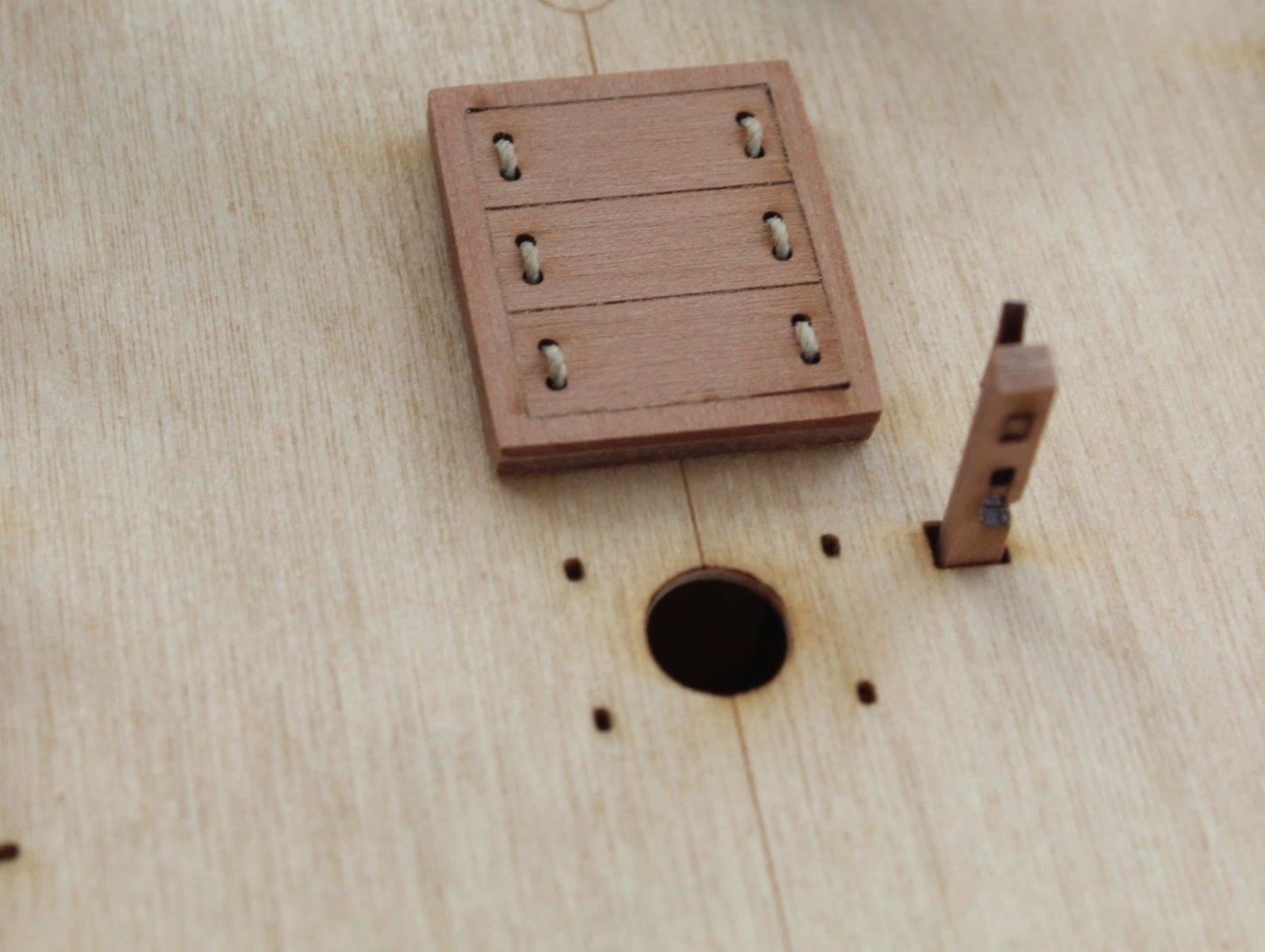
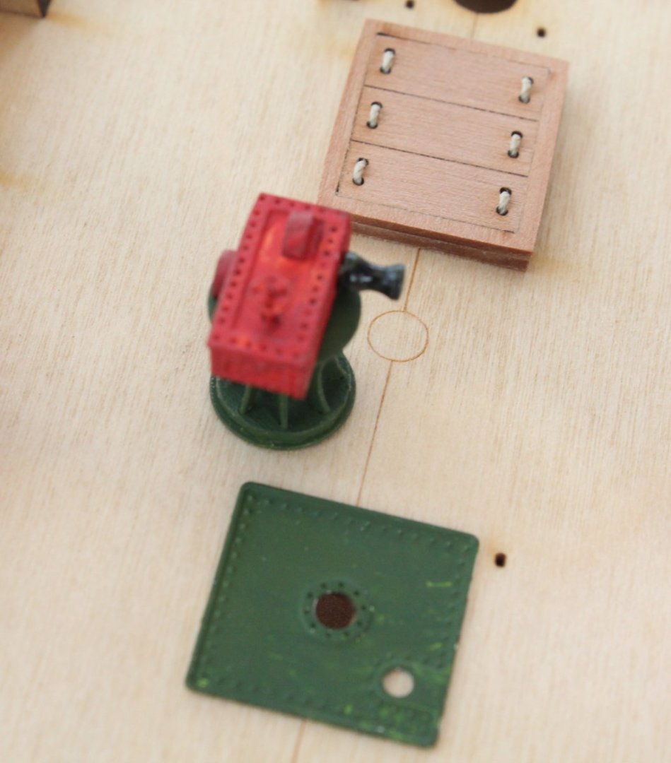
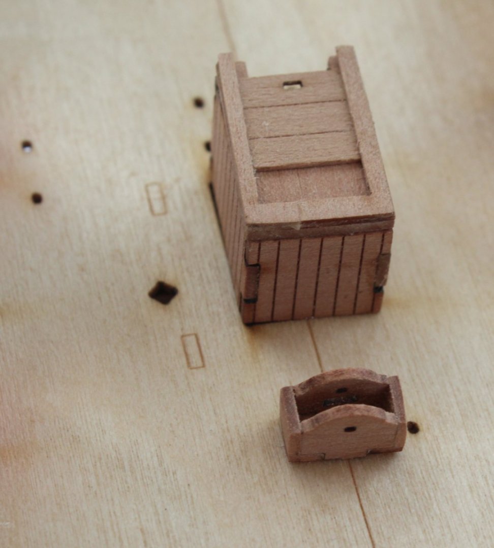
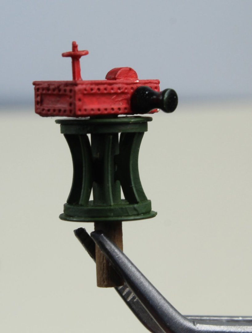
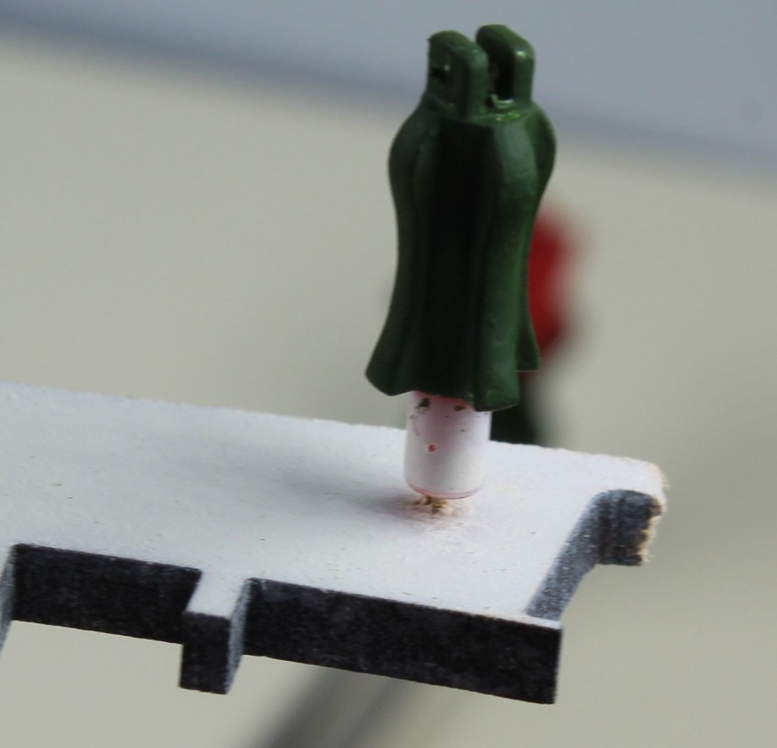
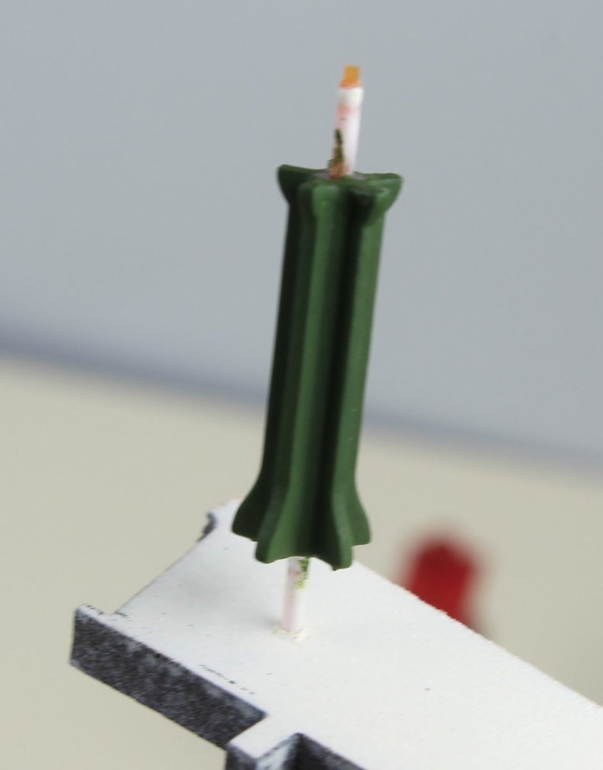
005 - Bulwarks, inner stern counter and more deck items The bulwarks had been left for 24 hours to fully dry out, clamped to the hull. With the clamps removed they had retained the required bend. Taking each bulwark in turn, the position of the bulkheads were marked and a small 0.5mm hole drilled for the brass pins. Glue was then applied to the bulkheads below the deck and along the deck edge and the bulwarks were then pinned in place. I was very happy with the end result. Once the glued had cured the inner stern counter was glued into place. So far so good, what could possibly go wrong. It was then I then noted the left-hand rear bulwark was a bit floppy at the stern end. On closer inspection I realised the outer left side stern counter had snapped at the point shown in the photo below. I think the damaged happened when the inner stern counter was clamped in place and was probably not sitting fully on the stern frame even though I thought I had checked that. In the photo below the damaged part has been glued back in place and you will not that I am using the transom rail to help ensure in is set in the right position Thankfully I was able to release the left-hand rear bulwark without too much effort and without damage. As can be seen in the photo below there is sone glue deposits and traces of the outer stern frame on the bulwark which I will need to remove. To remove the glue deposits the bulwark was soaked in hot water for 30 mins which did the trick. The part was then clamped back in place and will now be left to fully dry out (again). I will have to take care when fitting the part with regards to the inner stern counter. As can be seen in the photo below there is slight positional problem which needs to be avoided when the part is glued in place. I have now made the capstan assembly. As can be seen in the photo below the top red section is not fully seated (or glued) on the lower section at the moment. The instructions did indicate that the slot for part PE-45 (a small upright post) was missing from part PE-41 (top section). It suggested cutting off the unexposed length of PE-45 and glue directly to the small, raised position on PE-45. I opted to modify part PE-45 by adding the missing slot. The upper red section would have looked much so much better with an air brush paint job rather than a paint brush. Another tool to add to my wish list. The remaining green parts have also been hand painted.


- 106 replies
-
- 4
-
-
- Erycina
- Plymouth Trawler
- (and 3 more)