DONATION DRIVE - SUPPORT MSW - DO YOUR PART TO KEEP THIS GREAT FORUM GOING!
×


Glenn-UK
-
Posts
3,164 -
Joined
-
Last visited
Content Type
Profiles
Forums
Gallery
Events
Everything posted by Glenn-UK
-
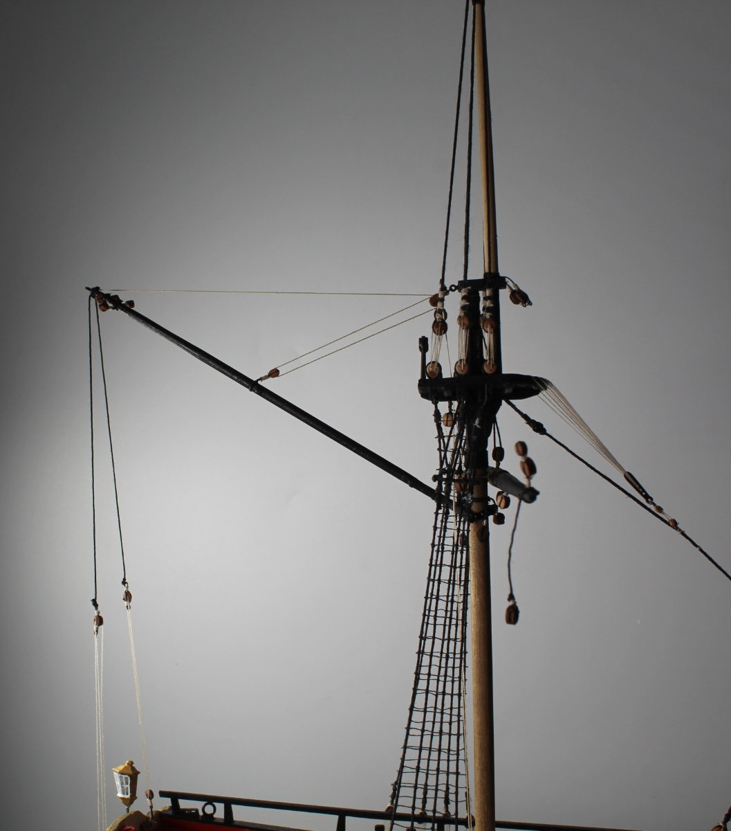
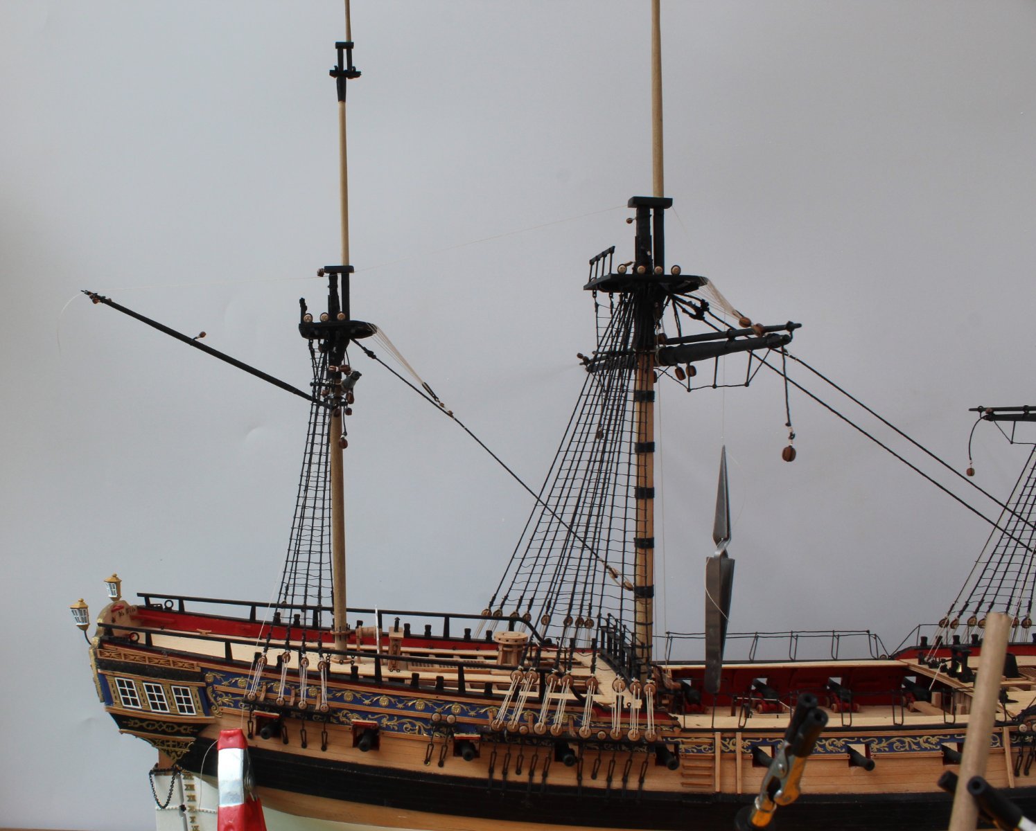
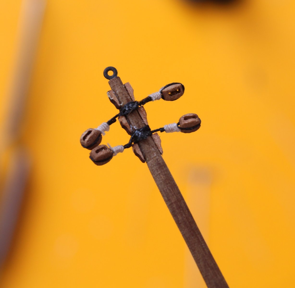
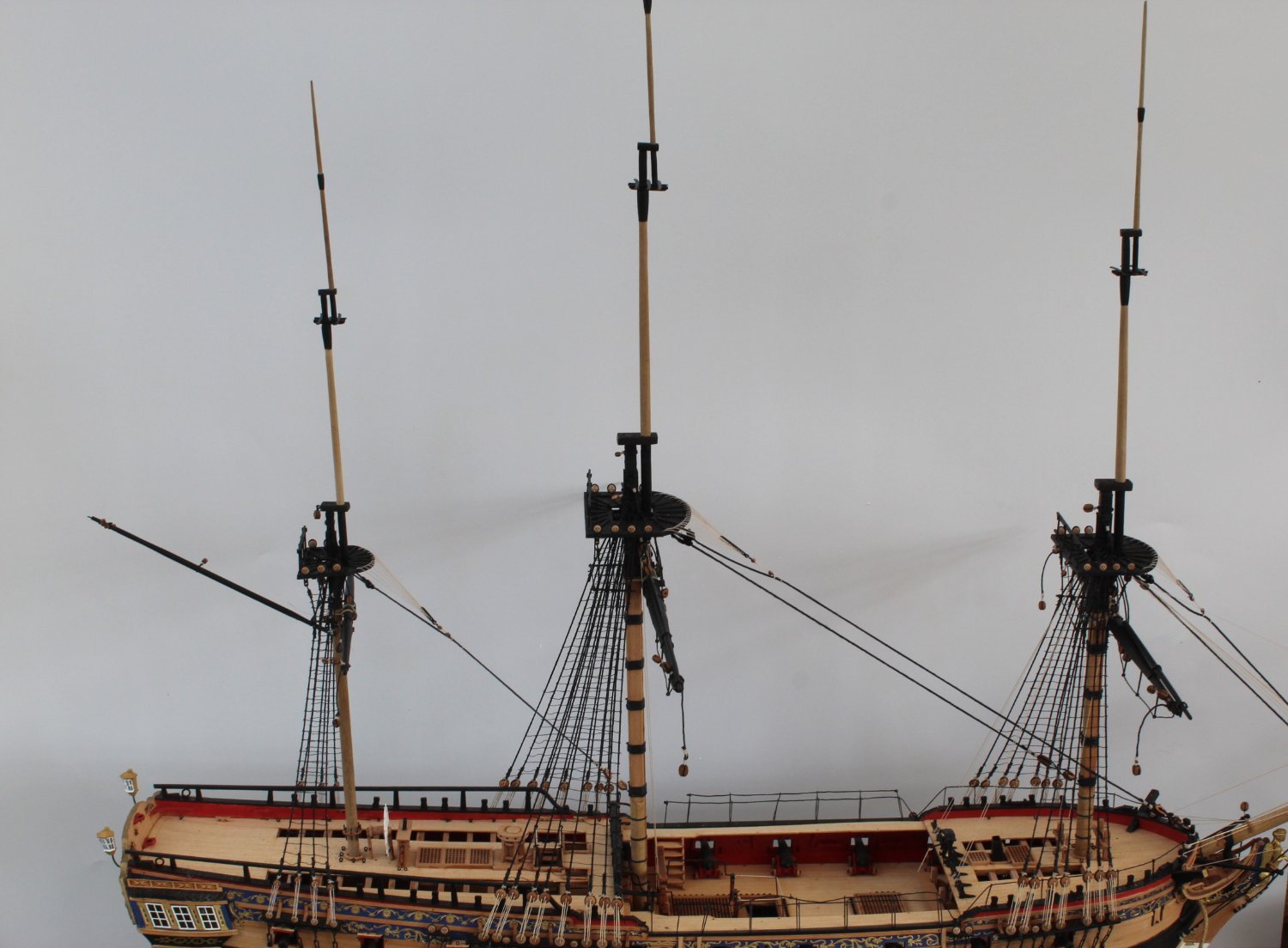
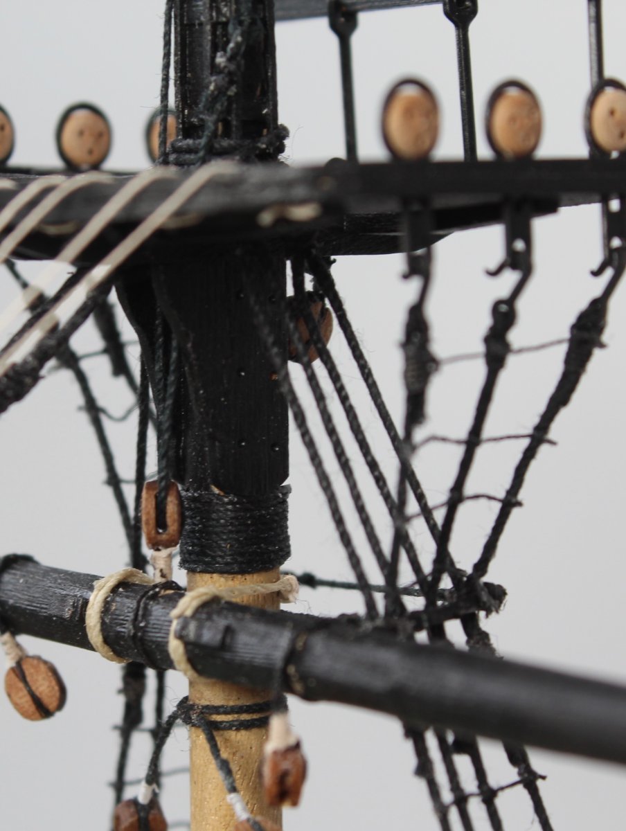
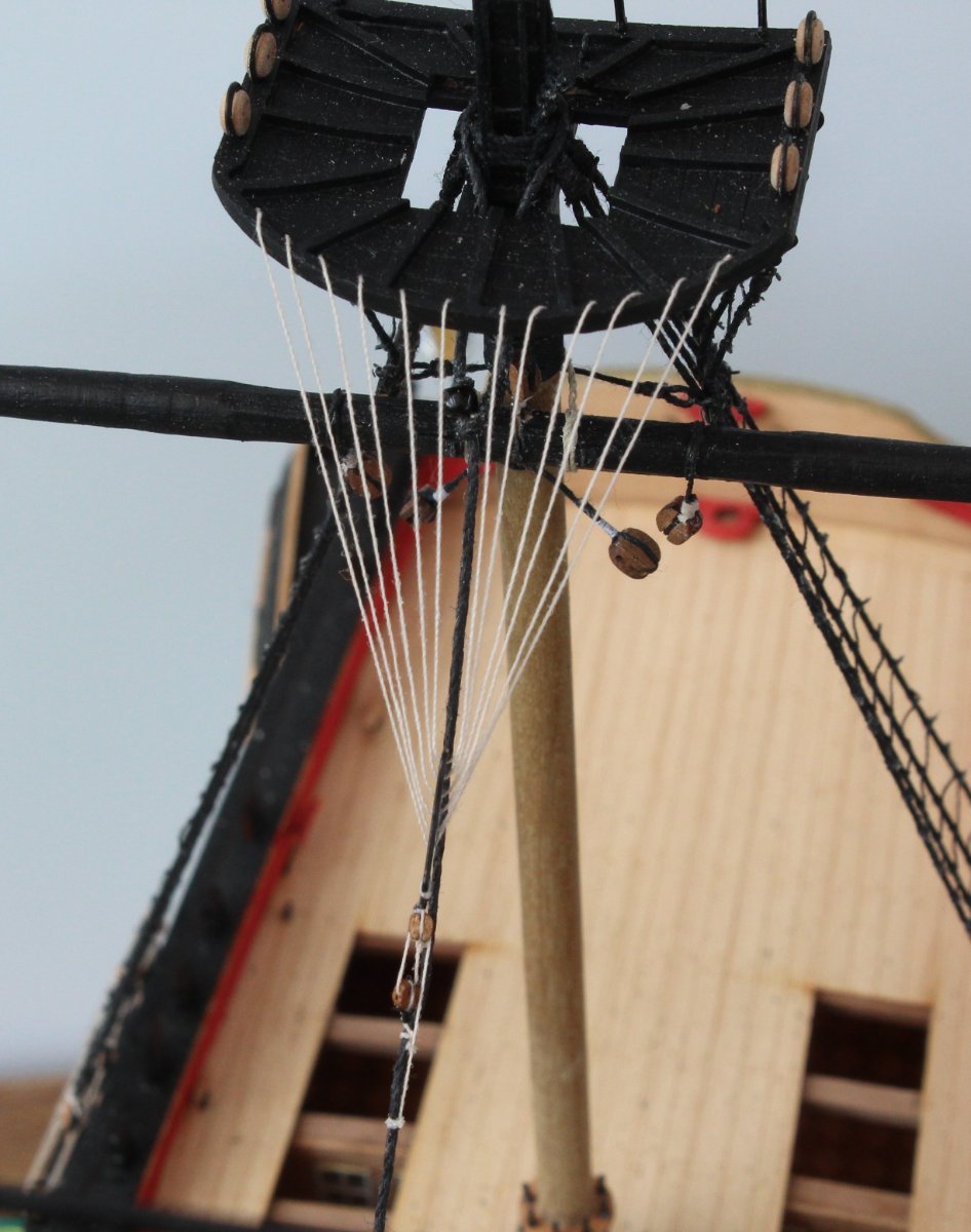
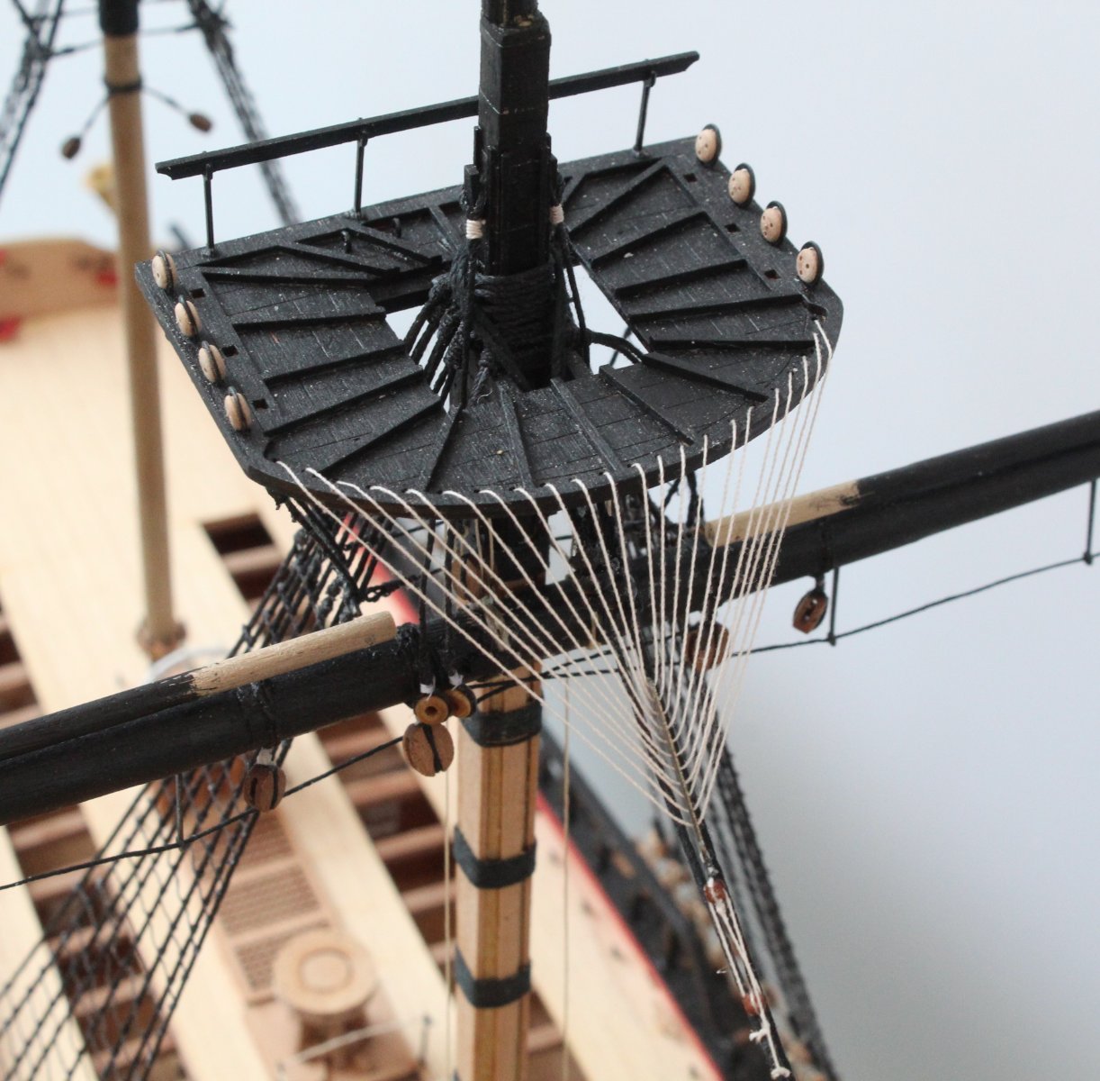
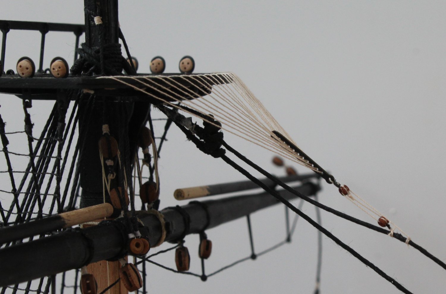
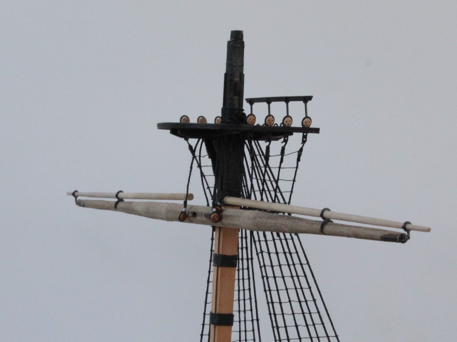
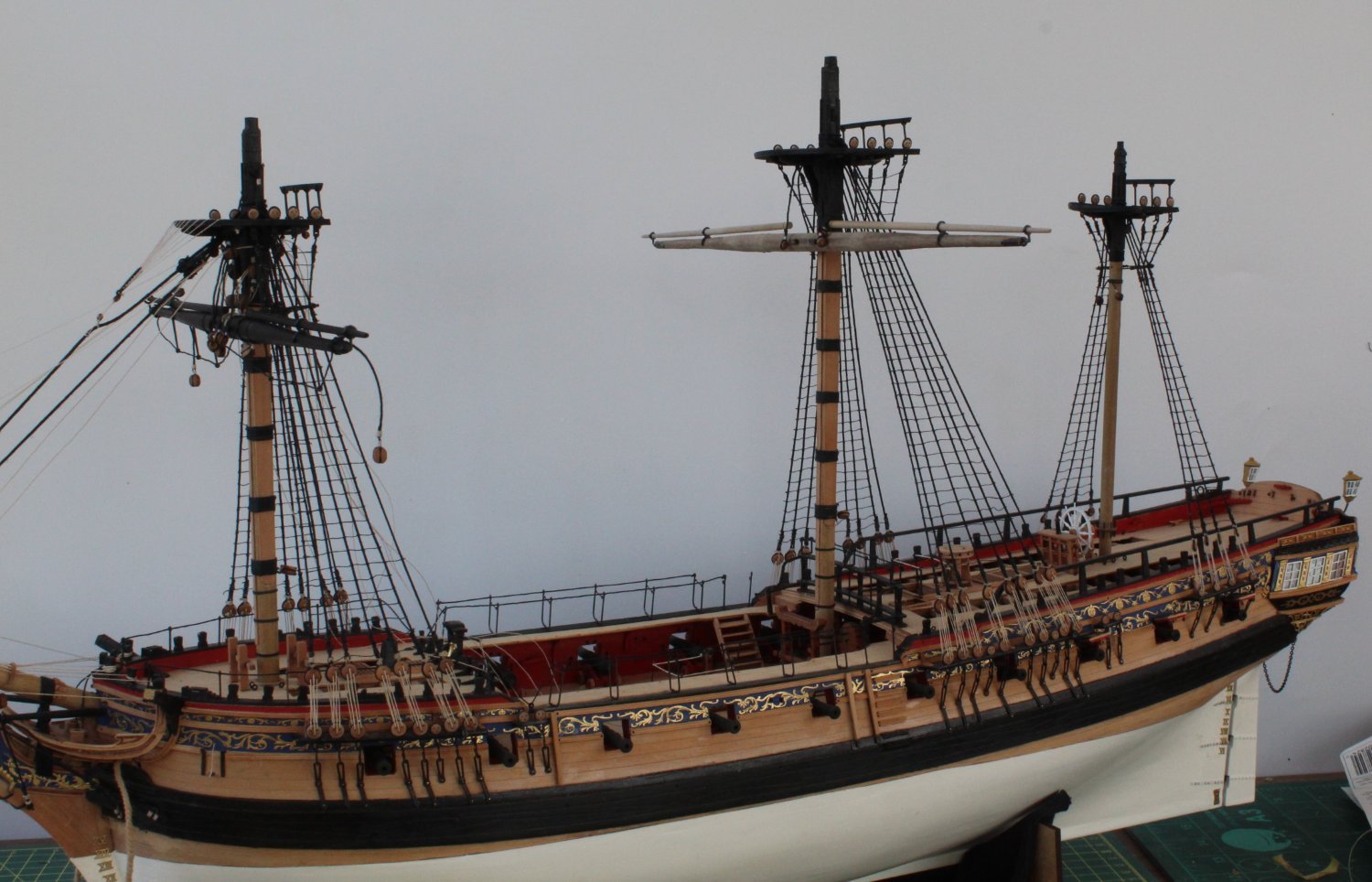
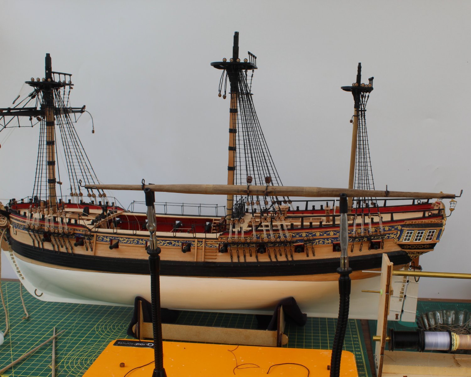
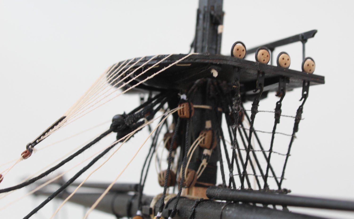
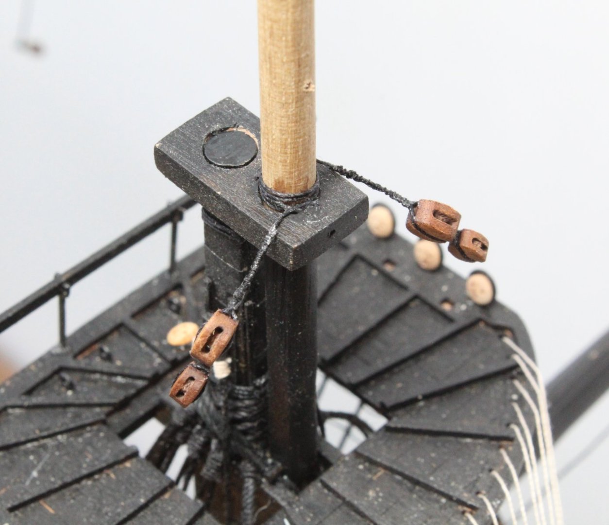
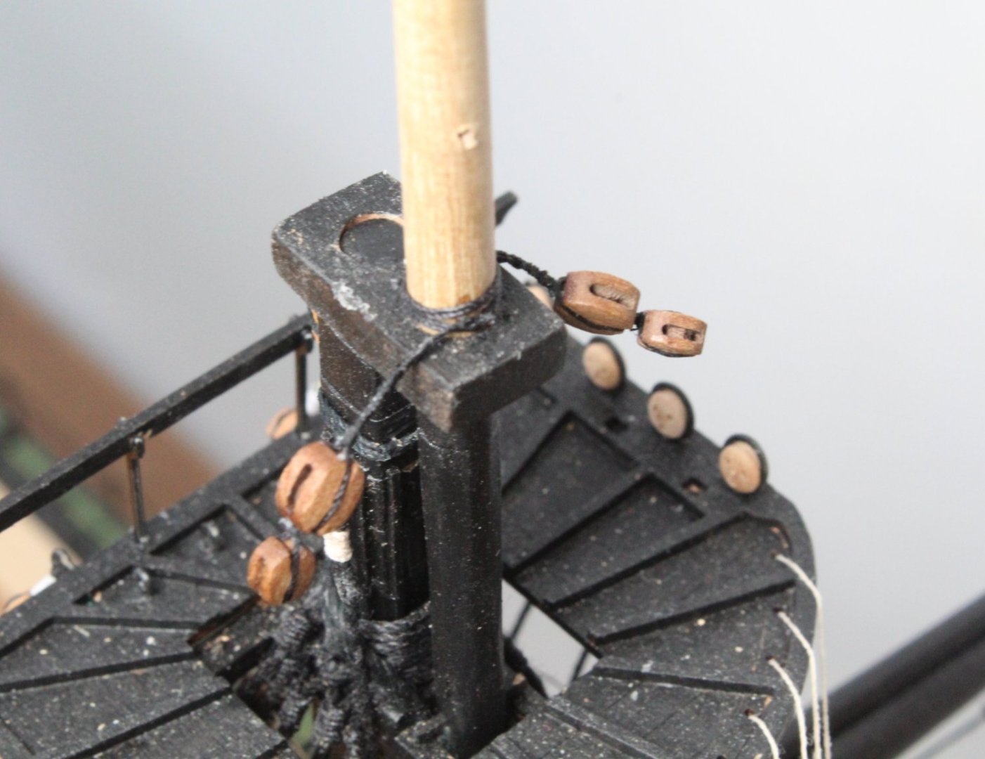
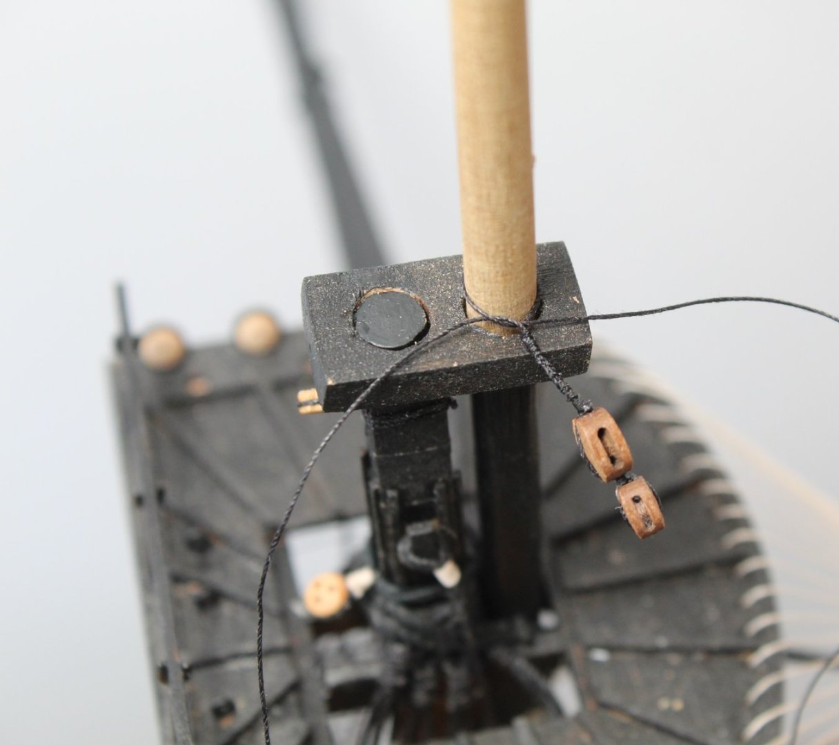
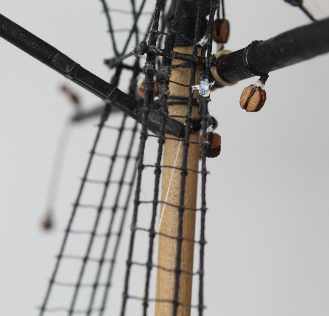
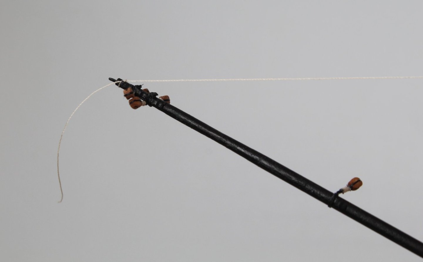
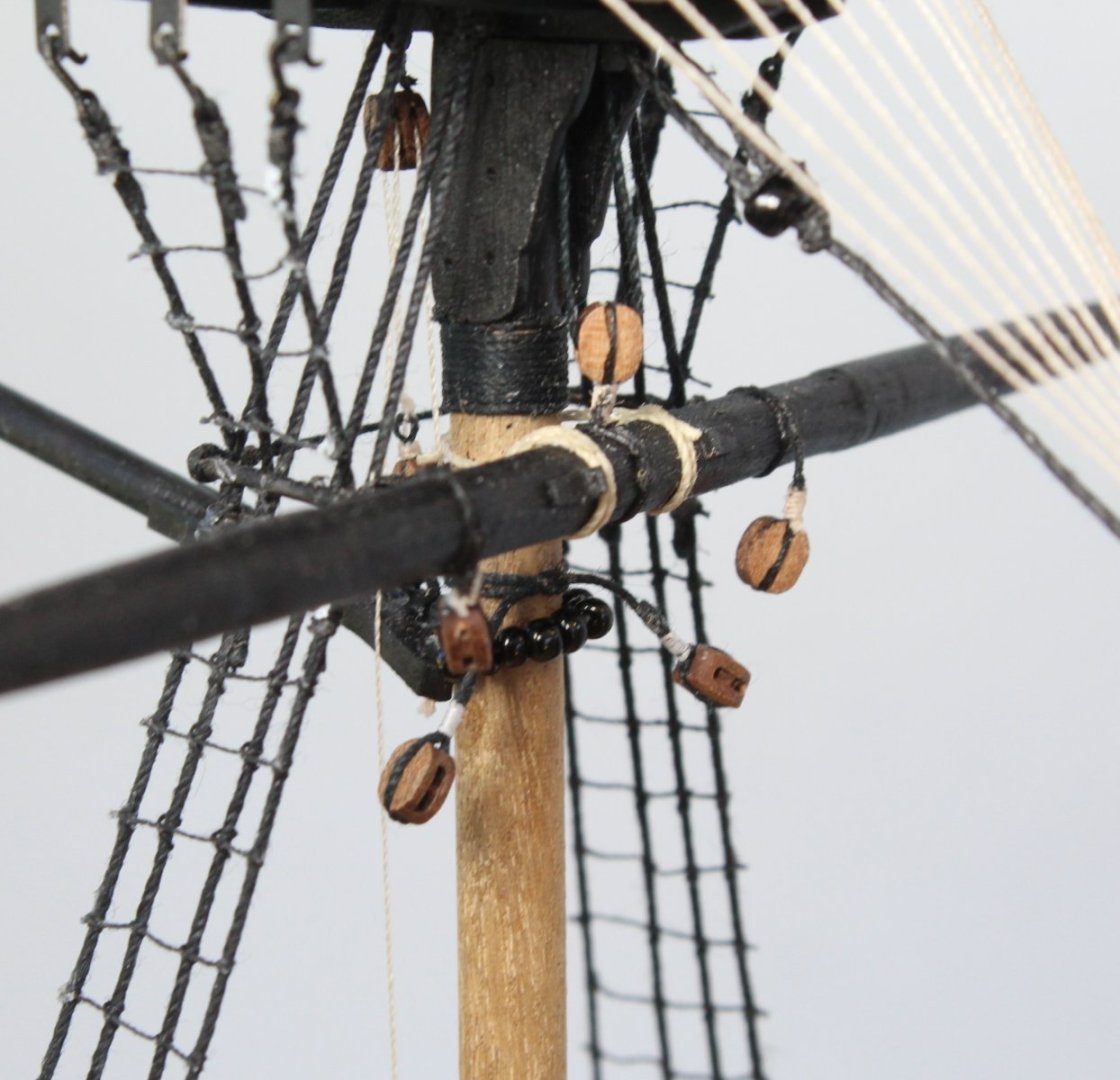
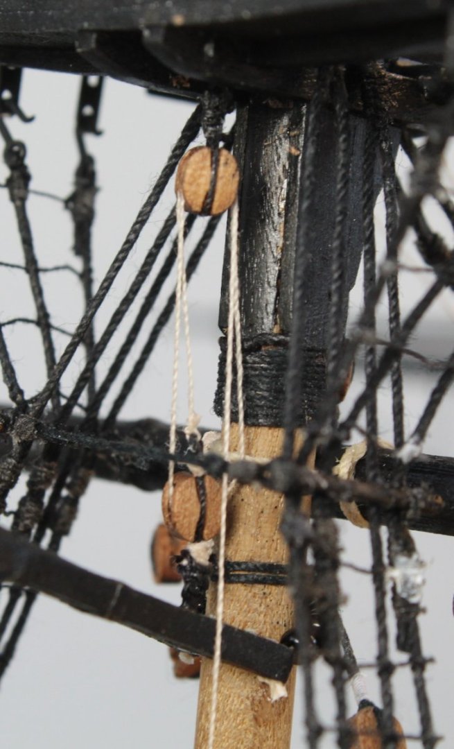
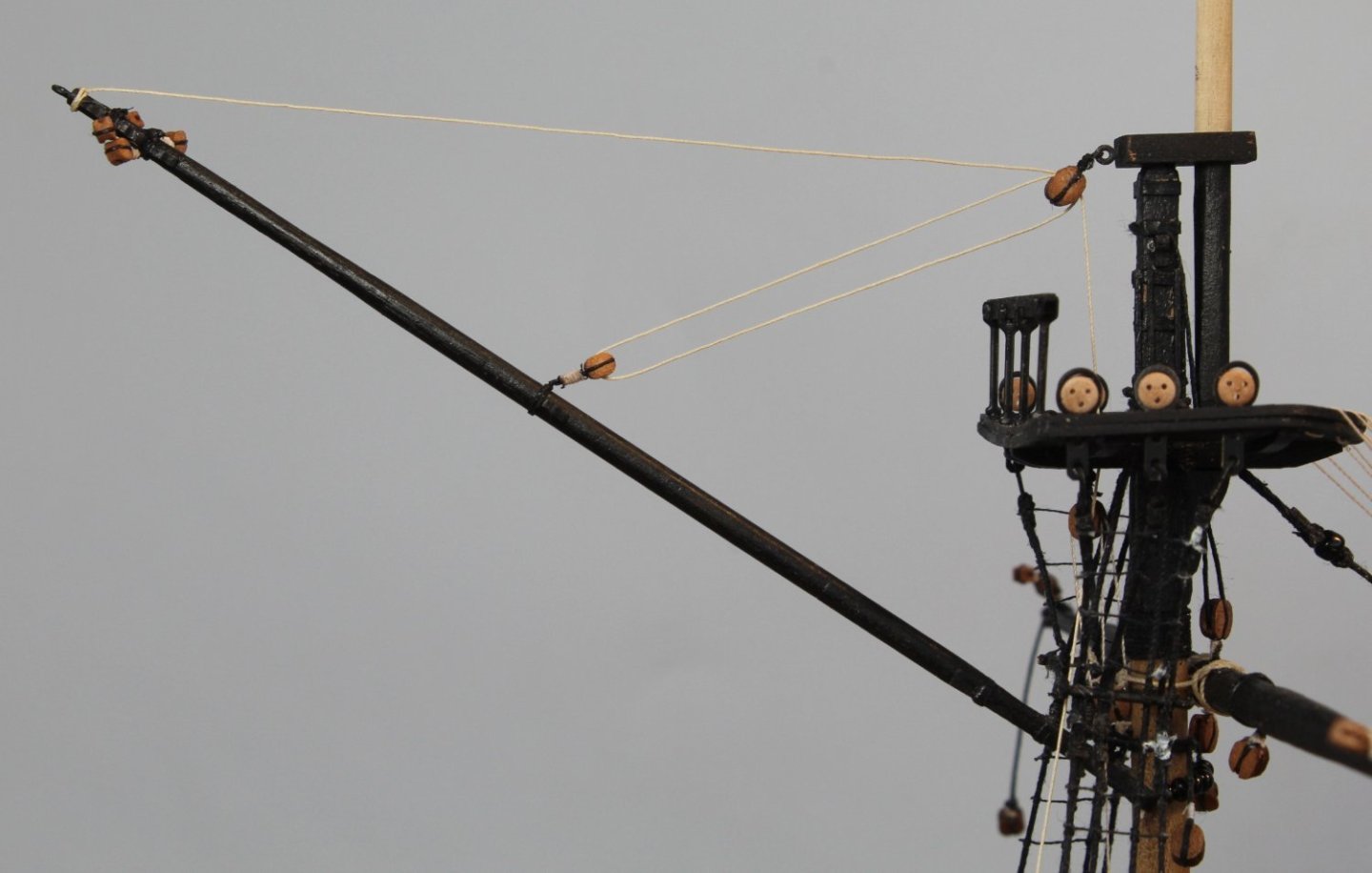
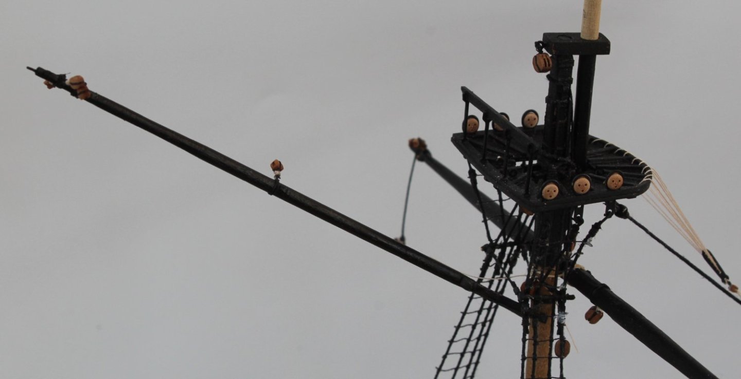
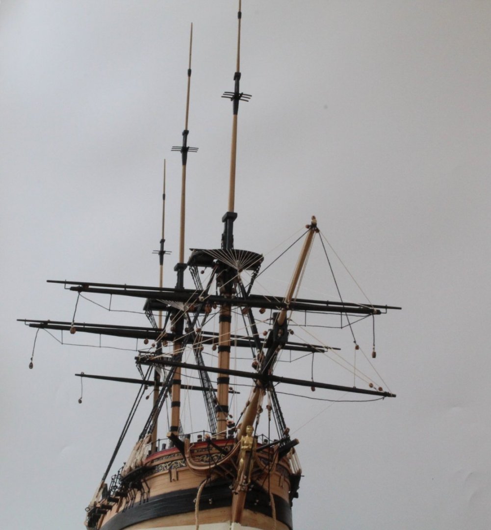
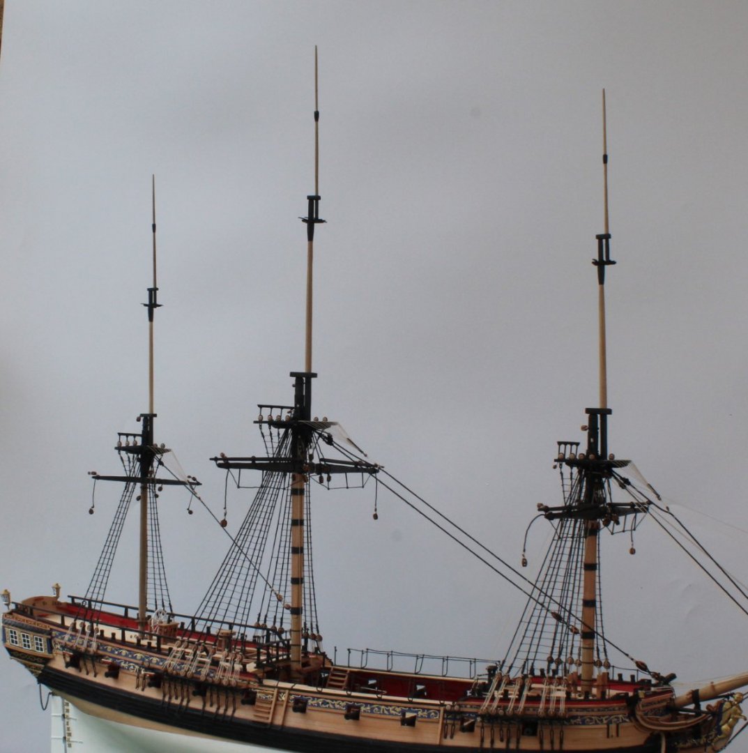
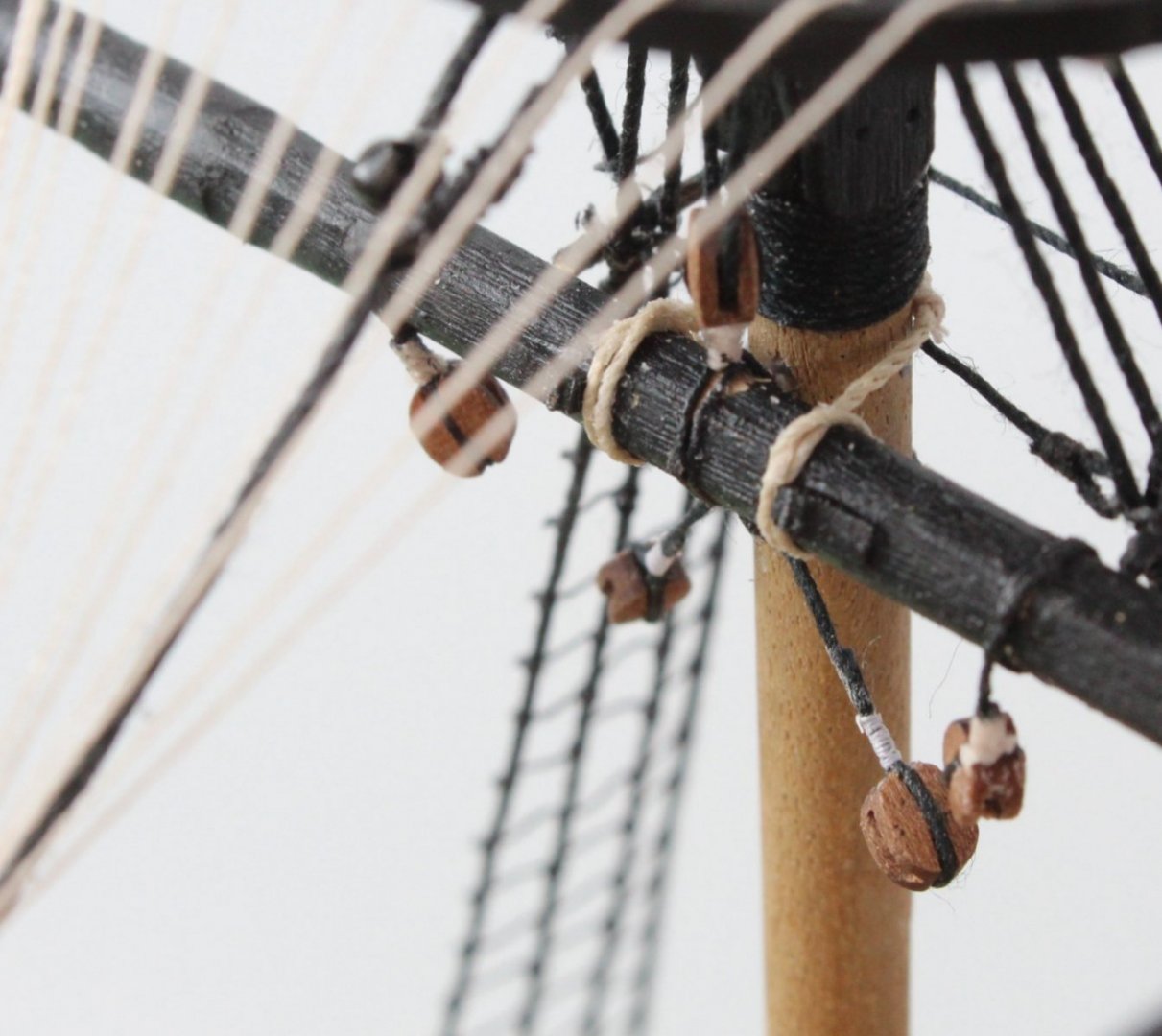
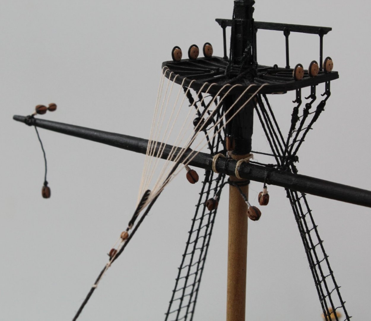
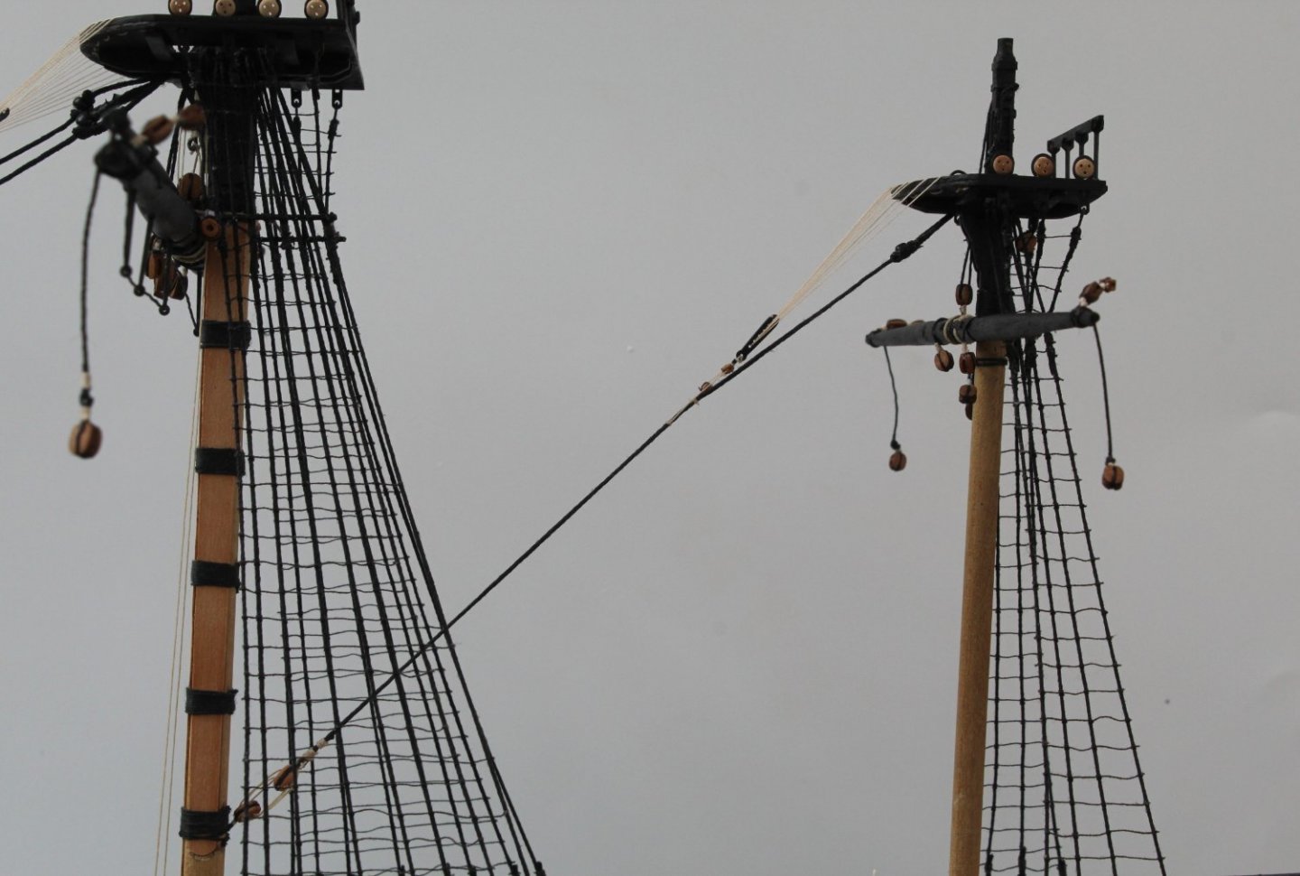
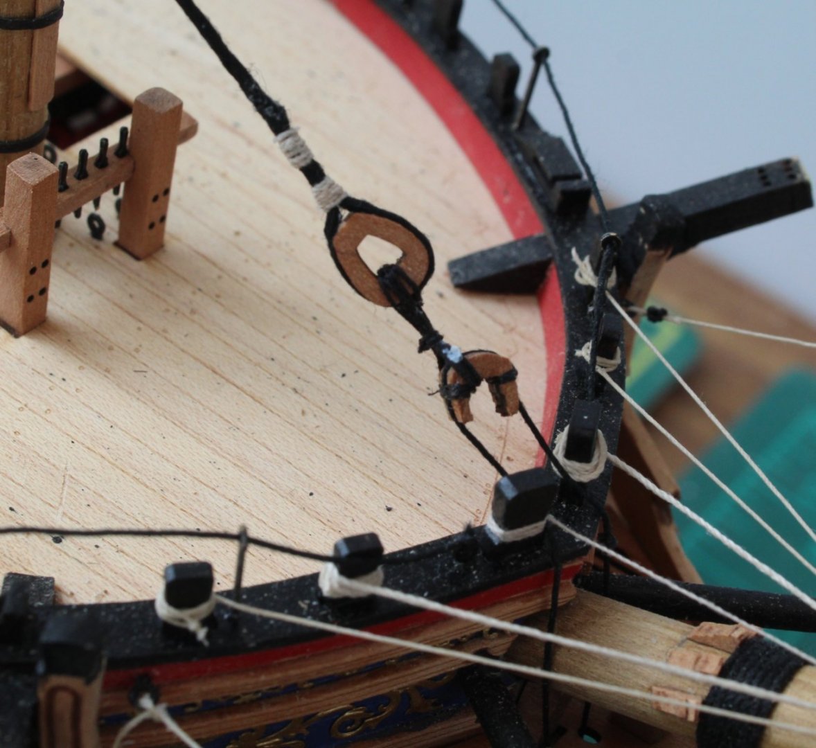
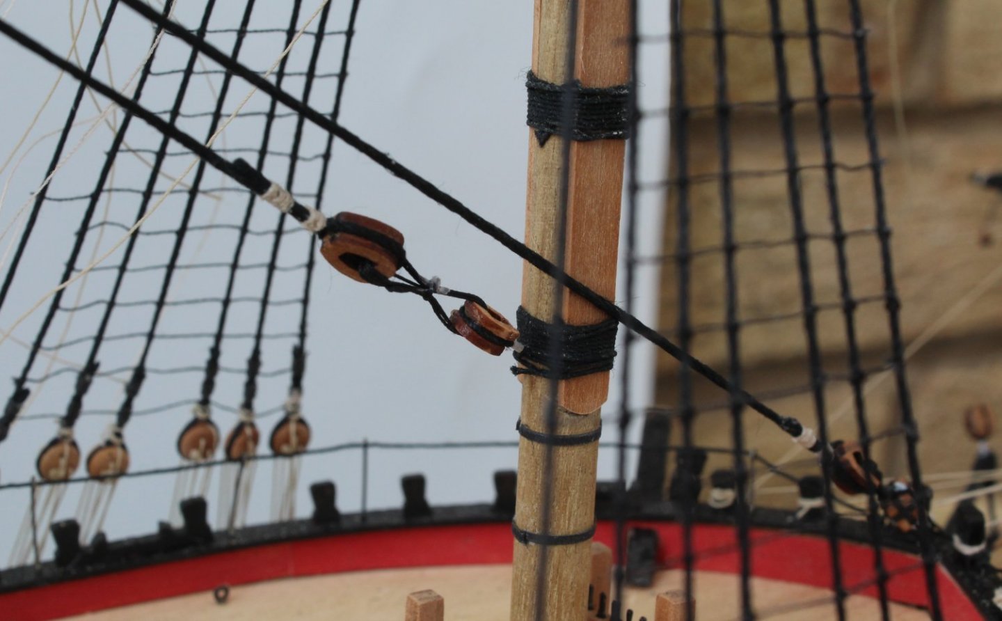
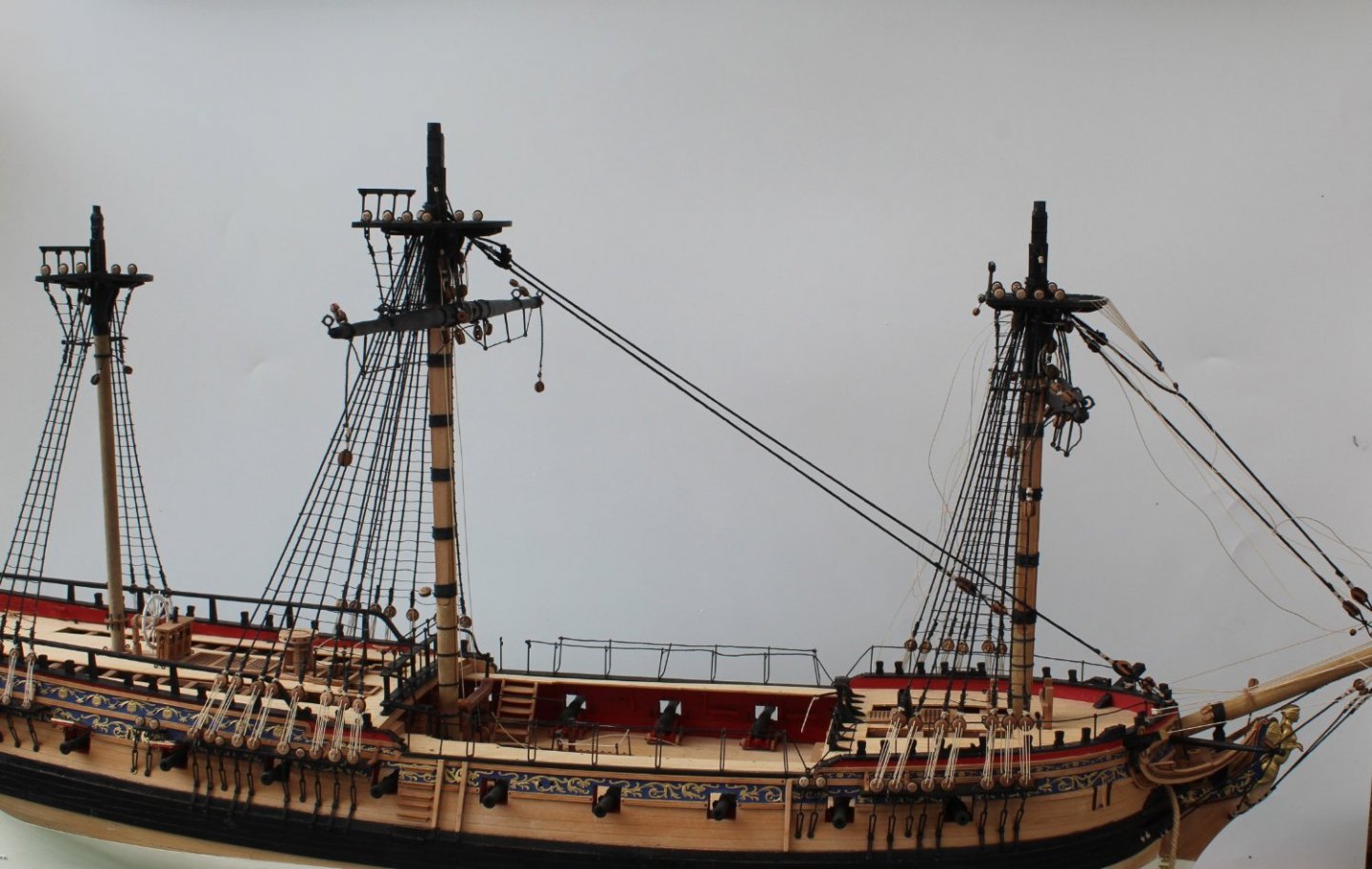
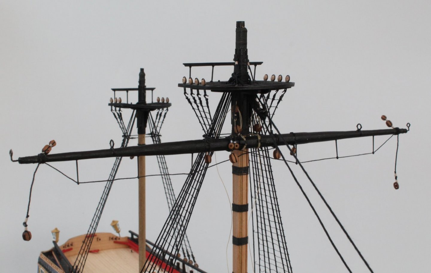
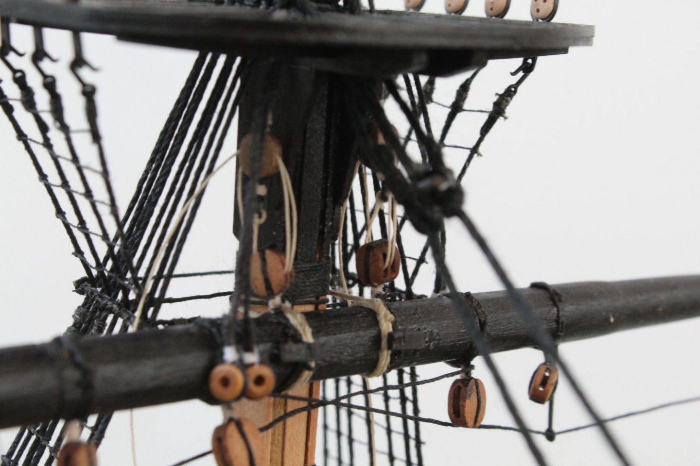
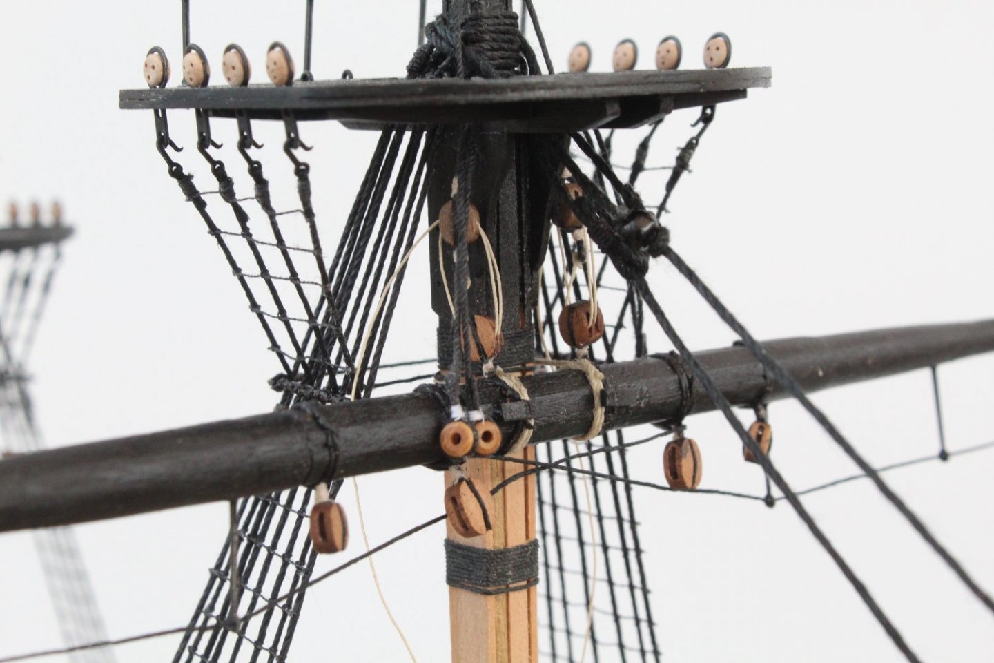
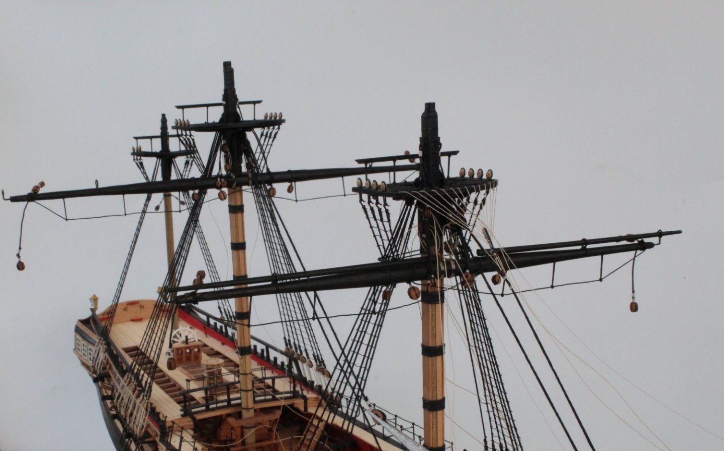
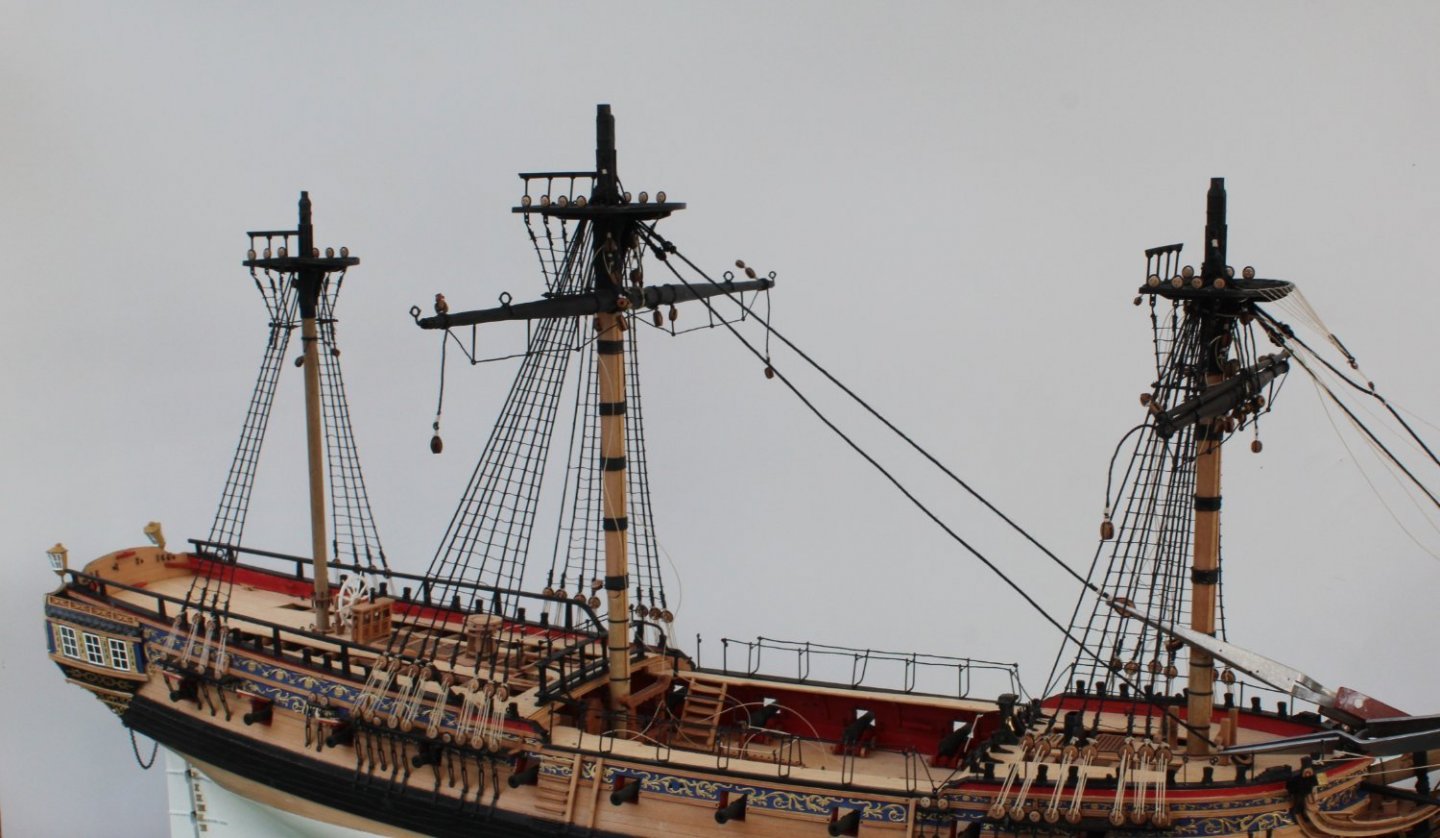
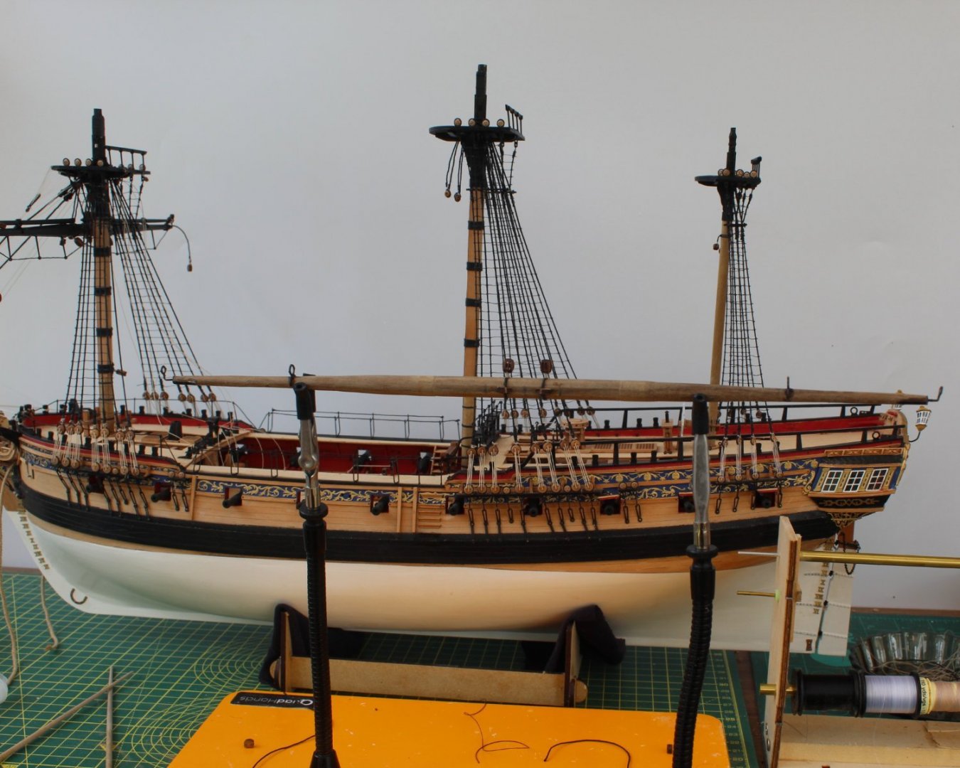
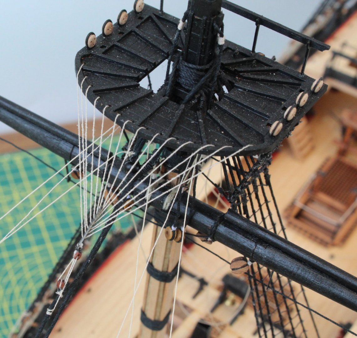
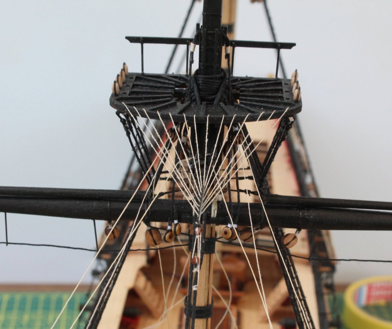
 Concluding Post on Fore and Main Yard Lift Blocks Following on from my last two posts I have now completed all the work related to both the main mast and fore mast yard lift block. The completed blocks were attached to their respective masts using a basic clove hitch knot which I have found to be the best way to secure blocks to masts and yards. The following picture shows the main mast yard lifts in place, noting there is hole above the endcap which has been drilled to accept the locating pin on the main topyard. The following picture shows the fore mast yard lifts in place, noting there is hole above the endcap which has been drilled to accept the locating pin on the fore topyard. I should really fill the top of the endcap where the foremast come through. I would need to buy some more wood filler as I have run out. I thought I would conclude this post with a picture of the Sphinx on the work bench where she now waiting for the both the main and fore topmasts burton pendants and shrouds to be added.
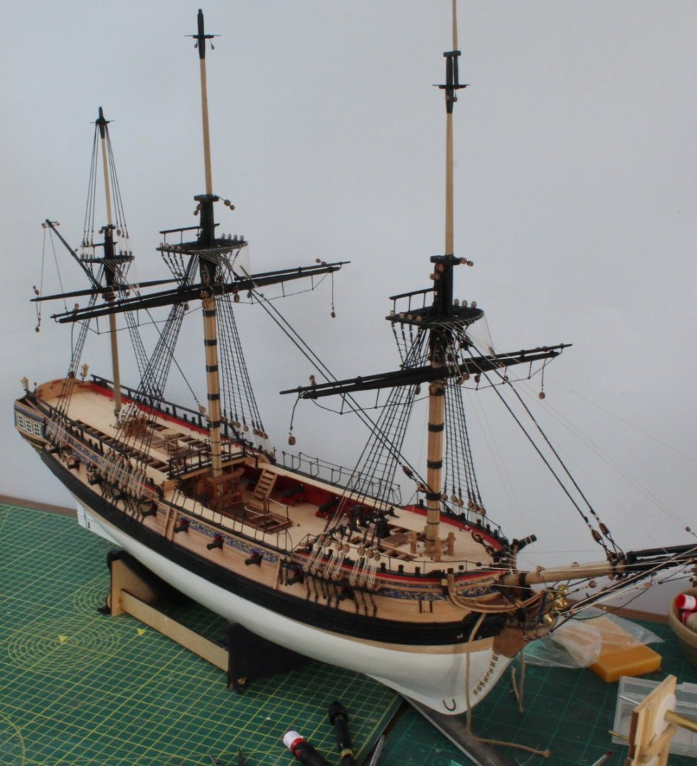
- 476 replies
-
- 6
-

-
- sphinx
- vanguard models
- (and 1 more)
-
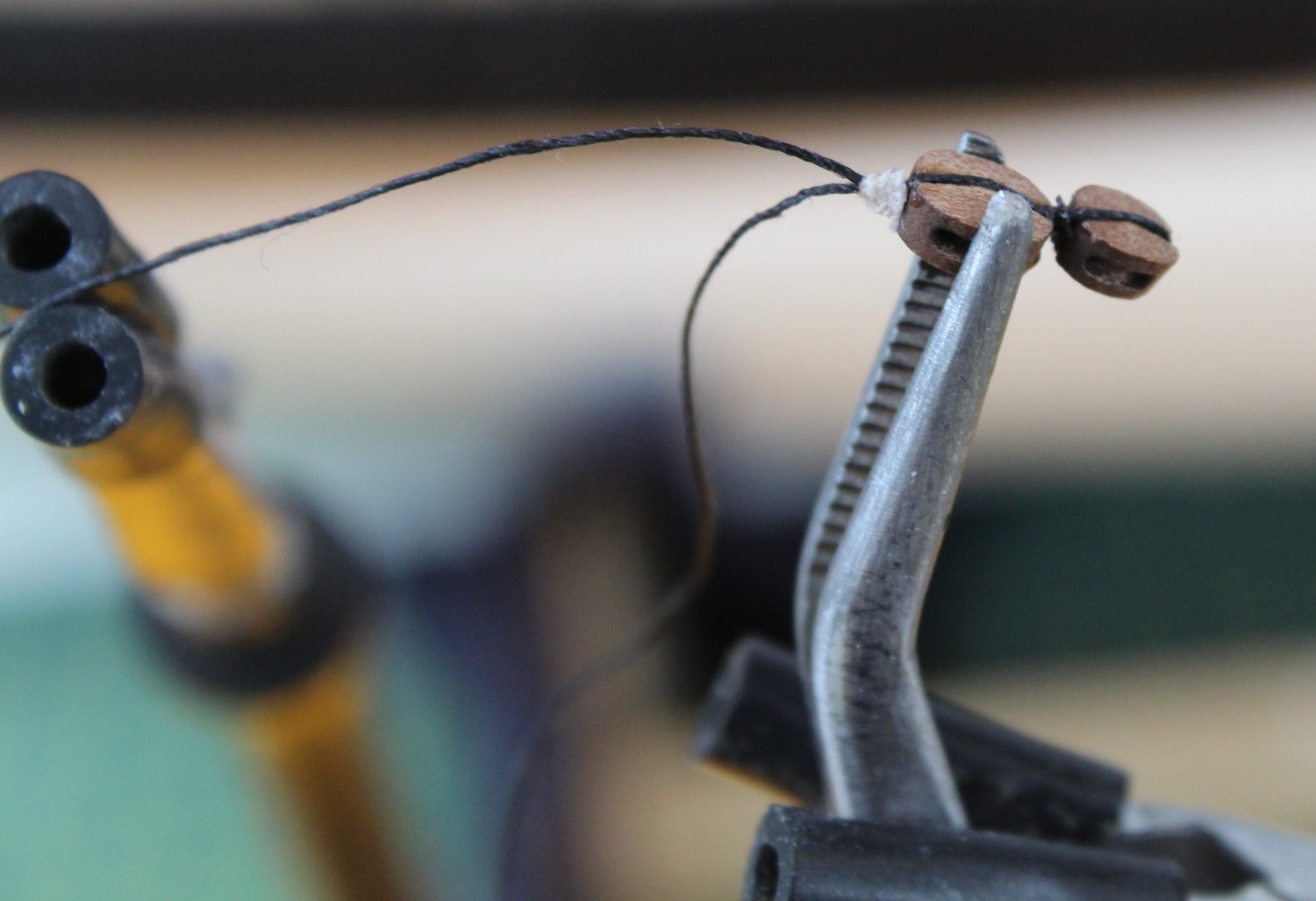
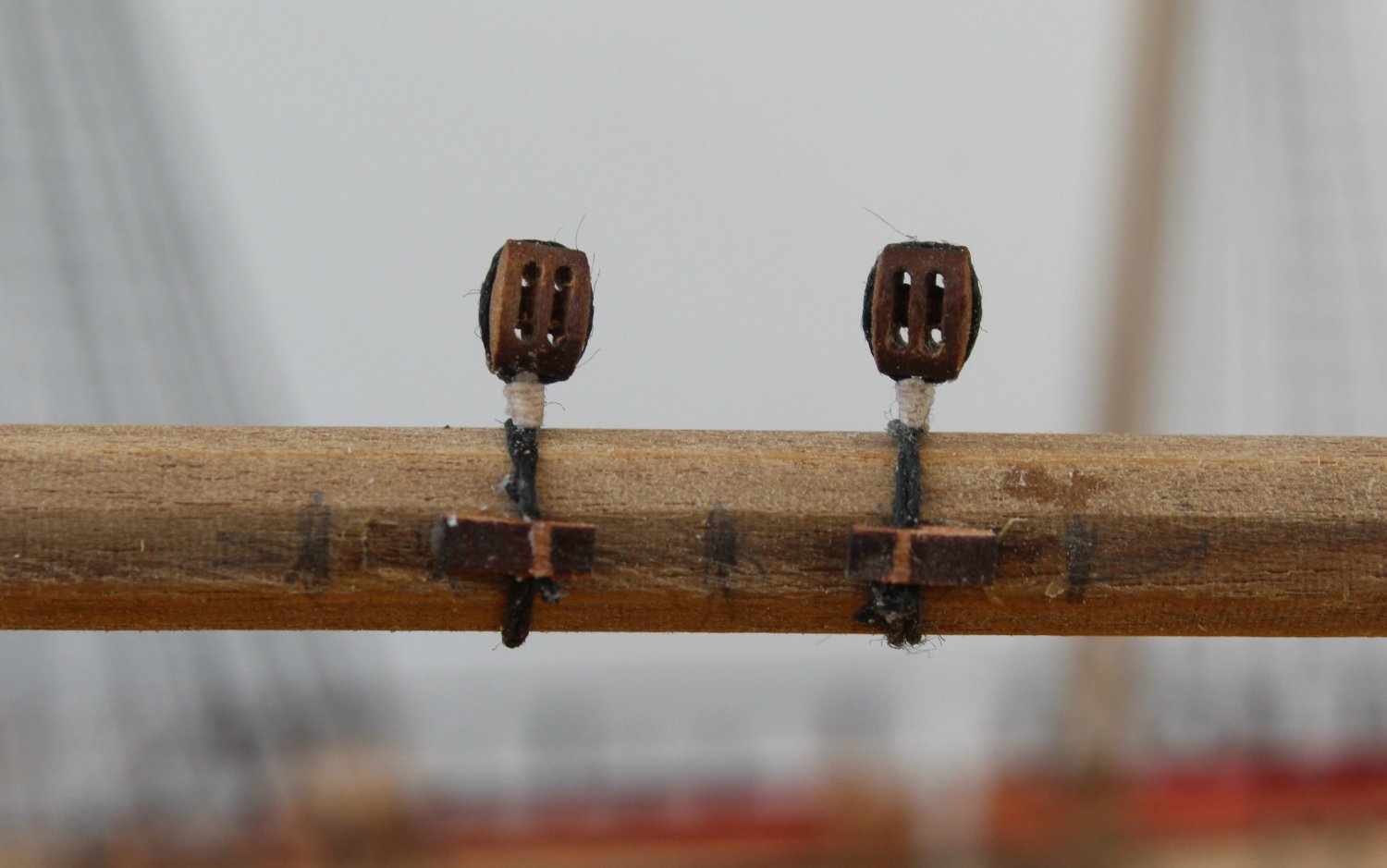
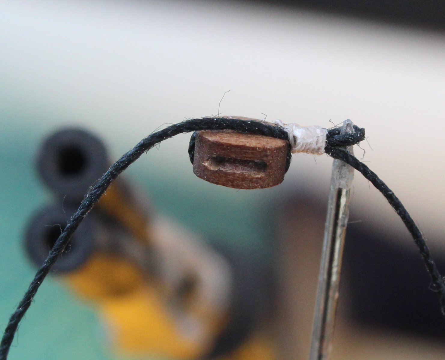
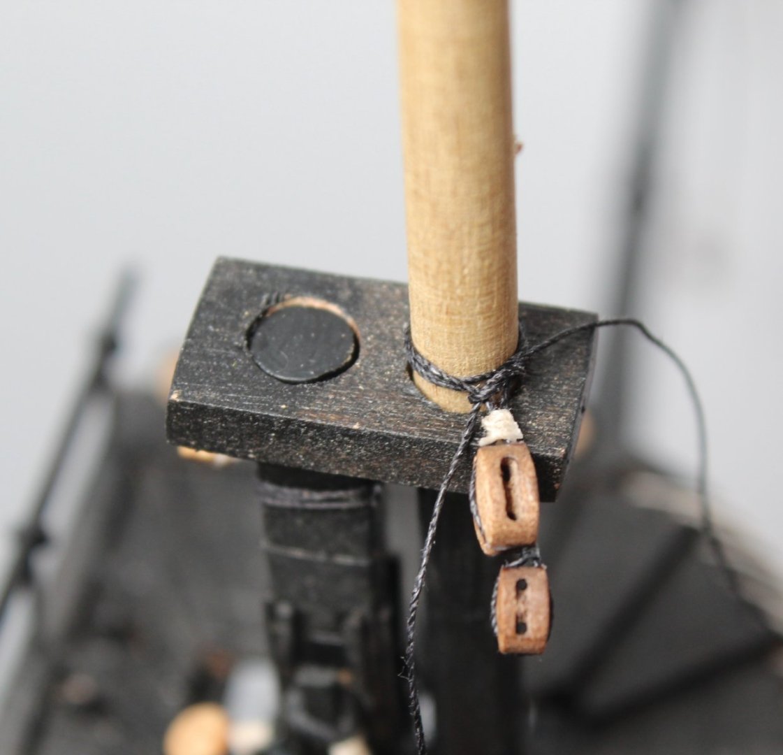
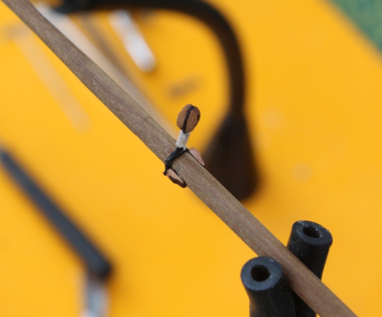
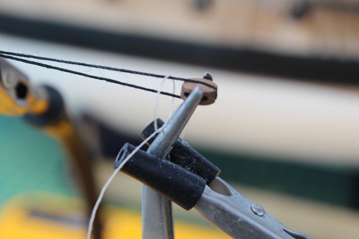
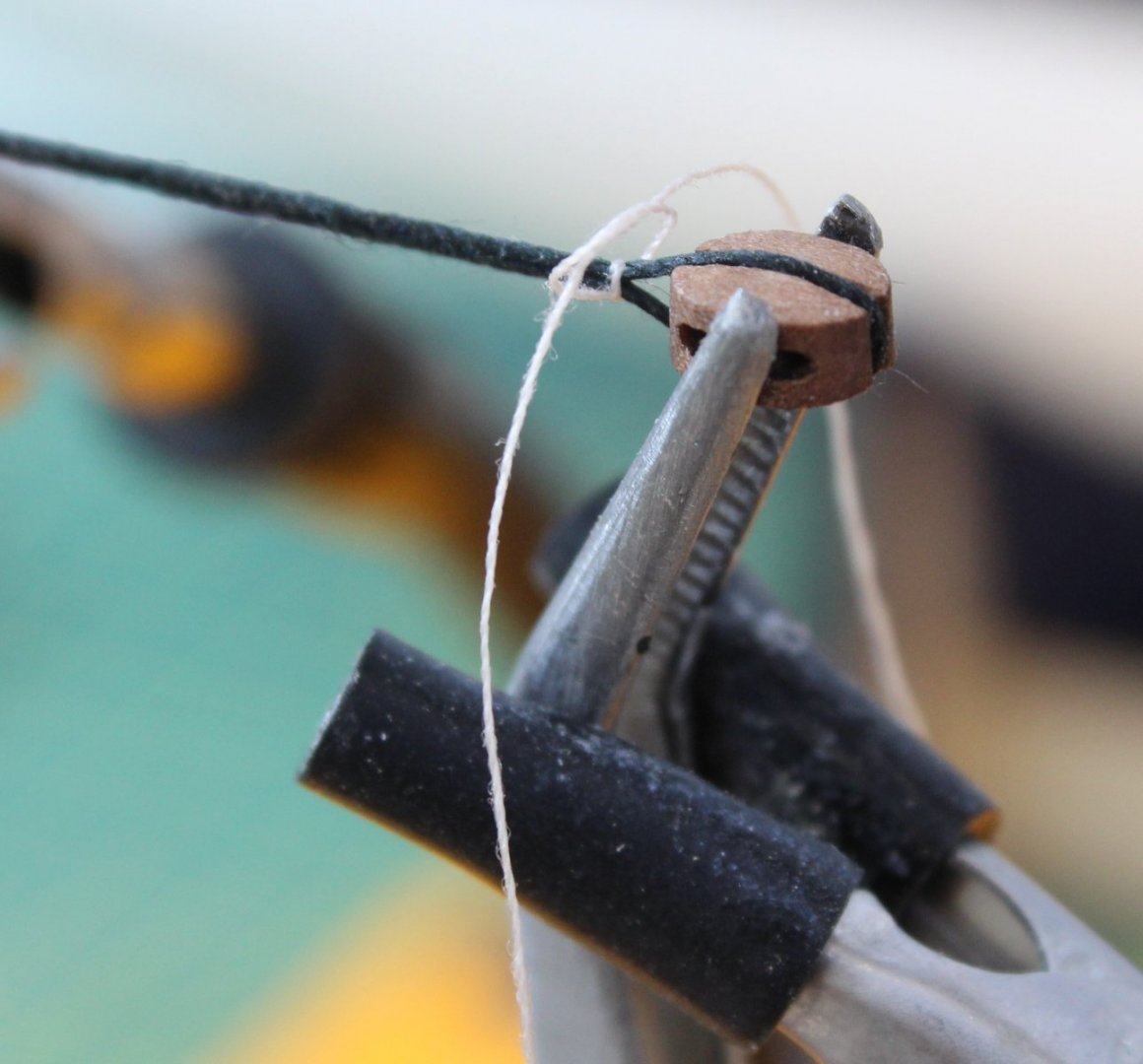
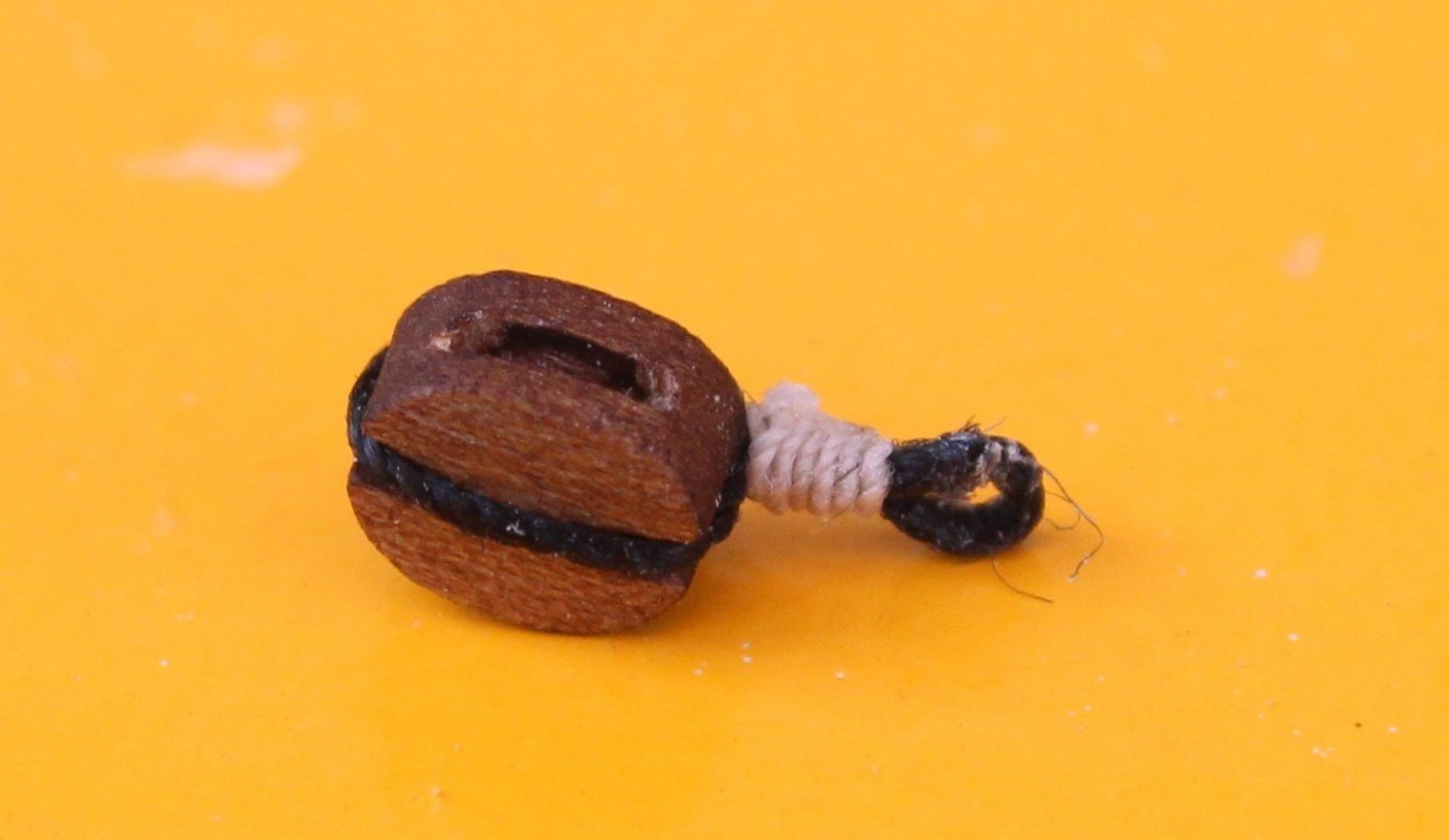
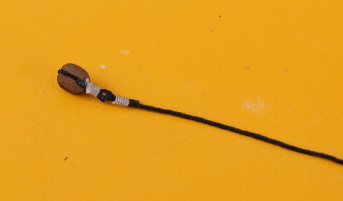
Following on from my last post I eventually opted to use black fly tying thread for the final seizing. With a bit of experimentation I decided on approx. 1cm of seized thread between the 5mm block and the mast. After a trial fit of the completed yard lift block assembly I am now very happy with the end result. I just need to complete the modifications the other three double block yard lift assemblies, one more for the main mast and two more for the foremast yard lift. It is a bit fiddly and difficult to see when using the very thin black fly tying thread for the seizing over the black thread wrapped around the block. It takes a bit more time and patience to get the job done but it is well worth the extra effort.
- 476 replies
-
- 3
-
-
- sphinx
- vanguard models
- (and 1 more)
-
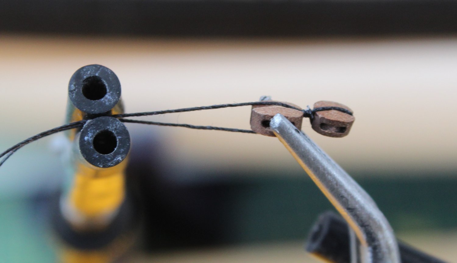
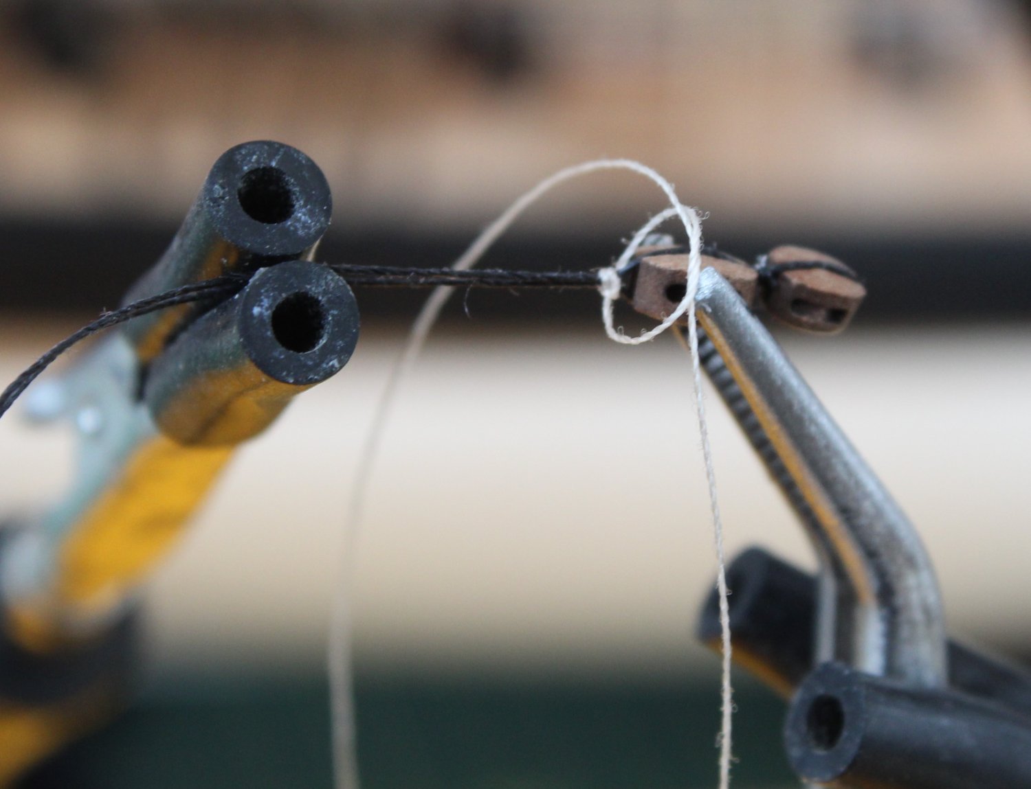
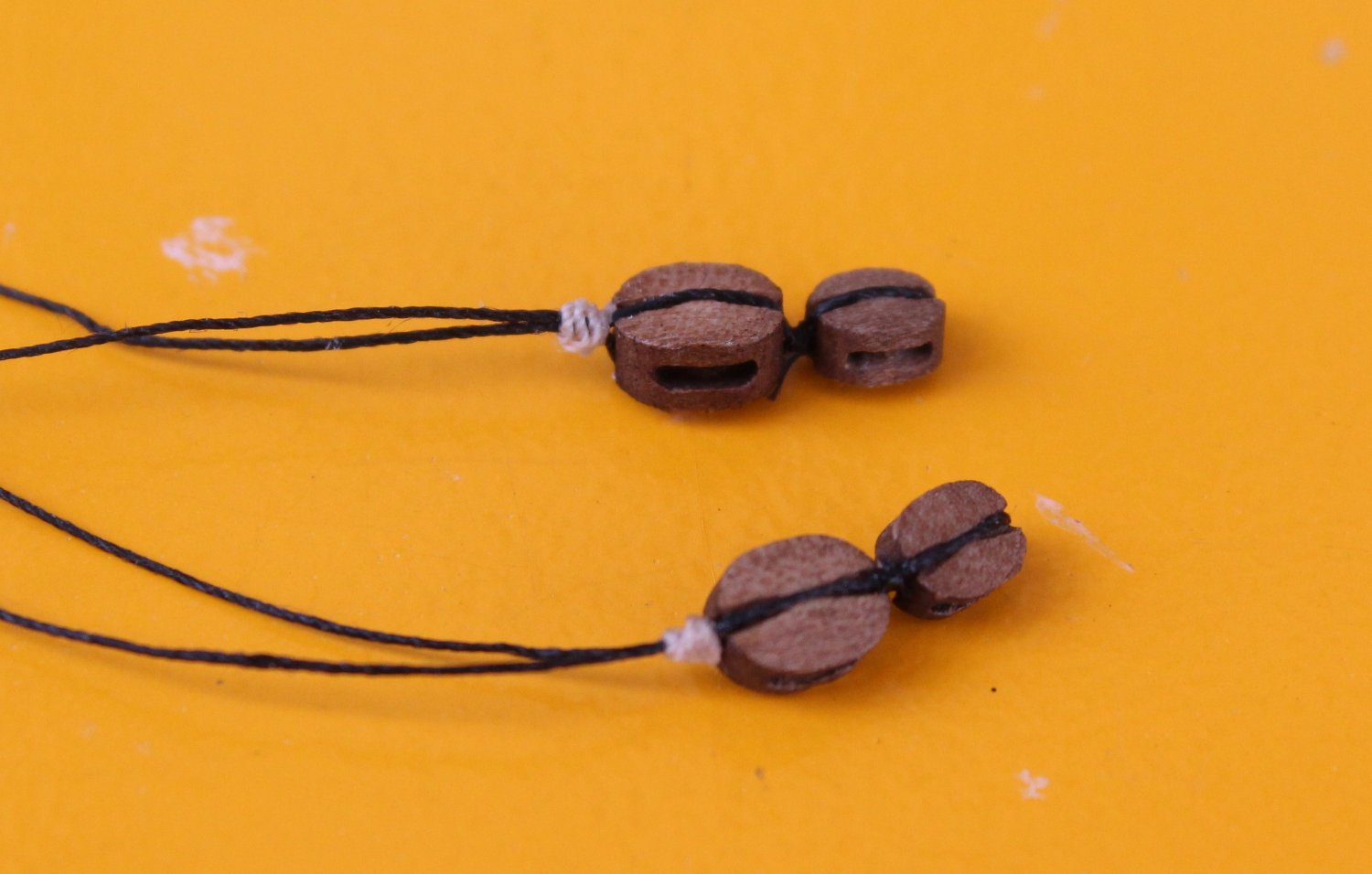
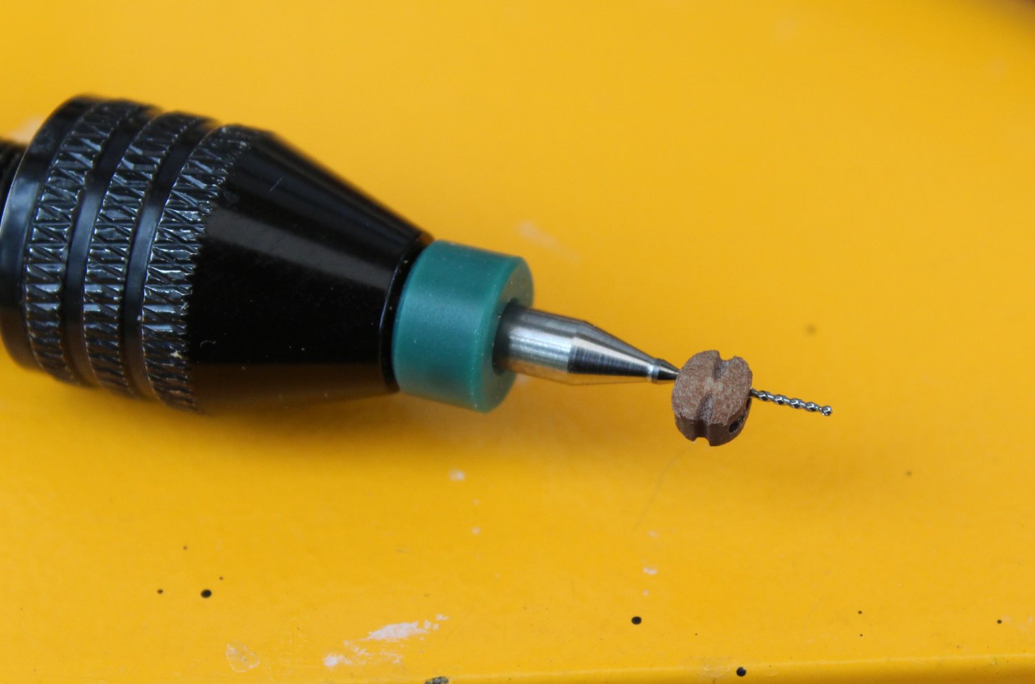
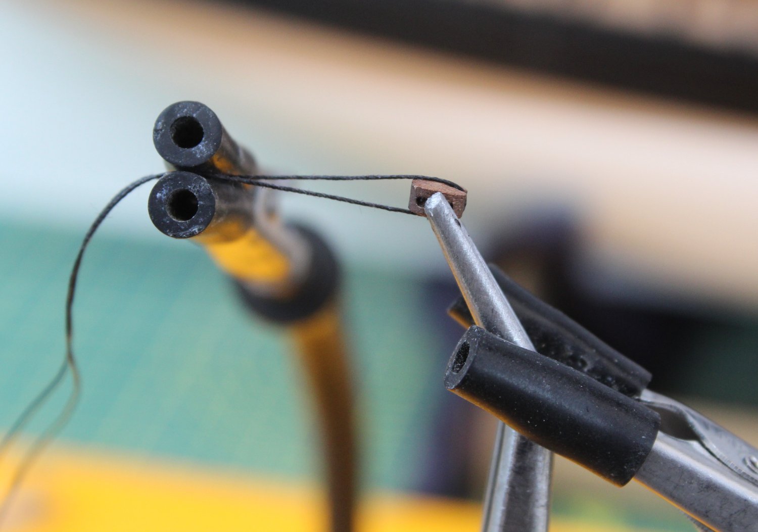
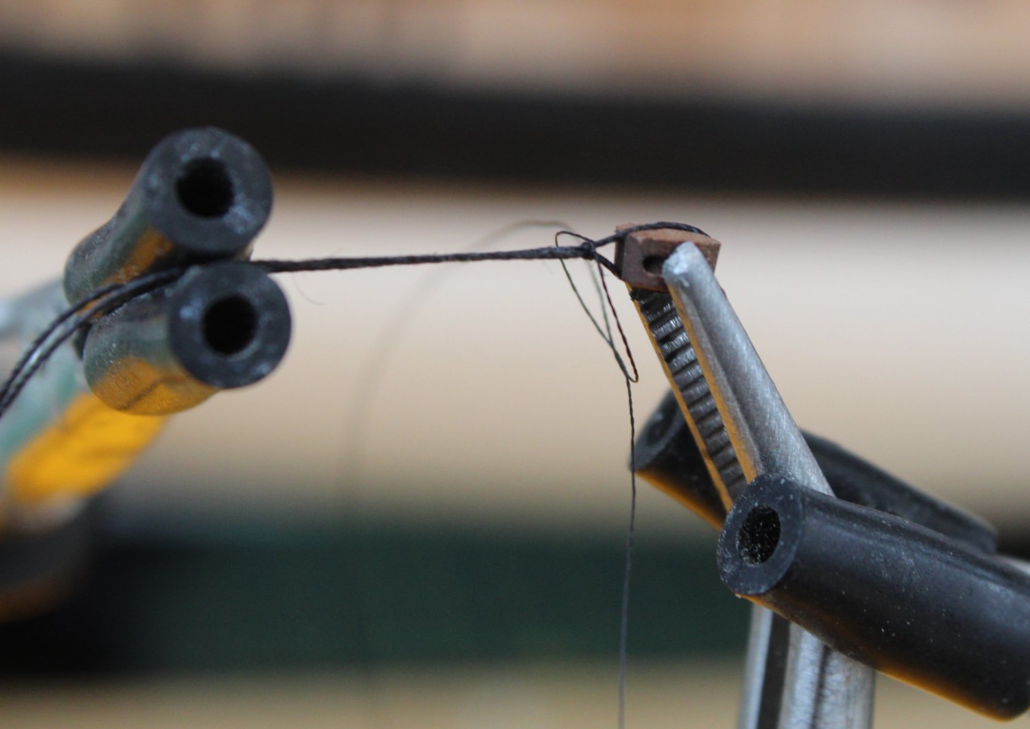
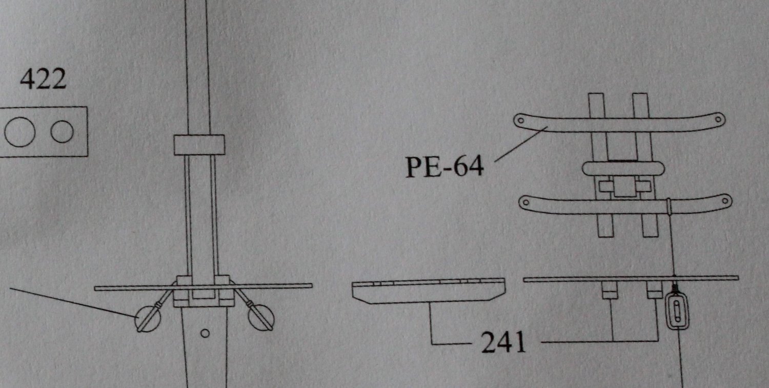
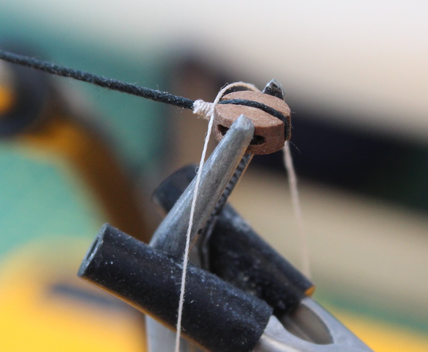
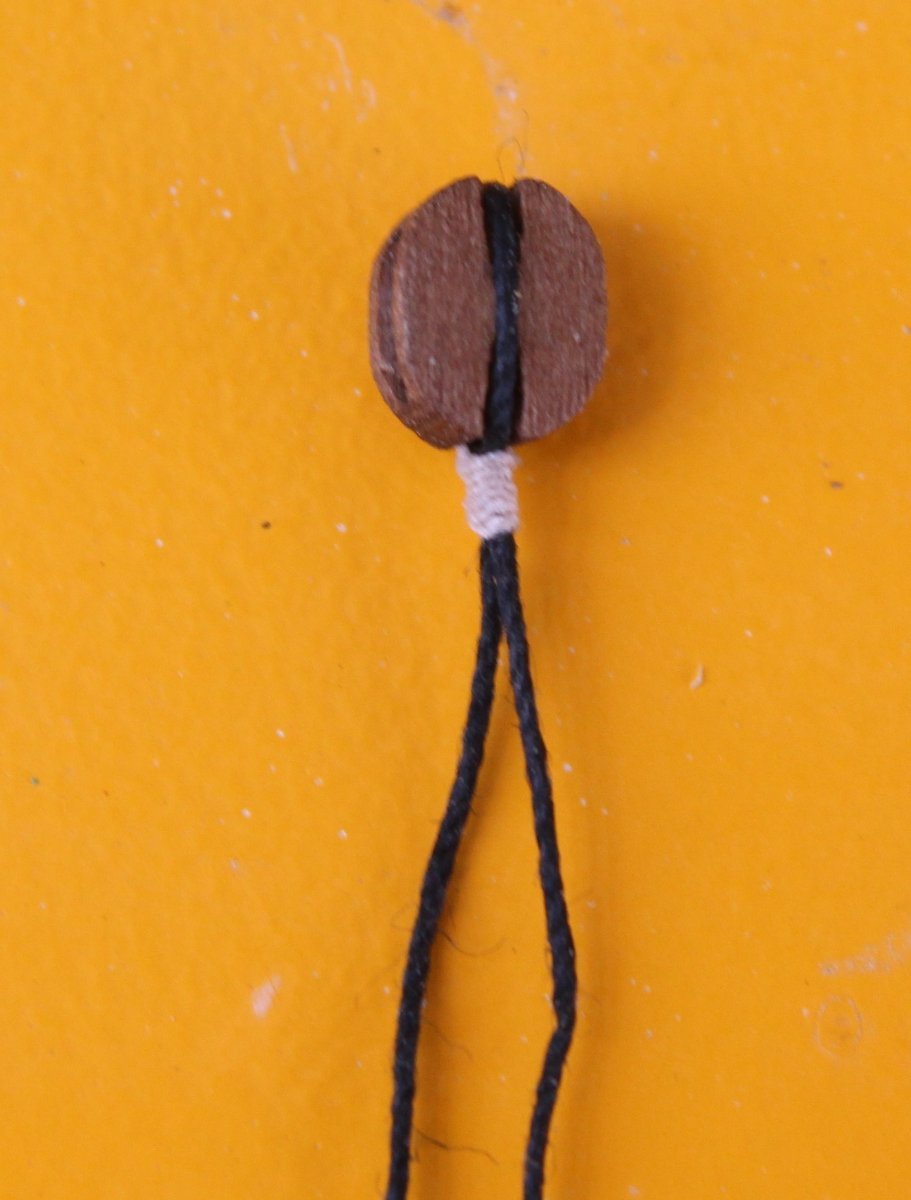
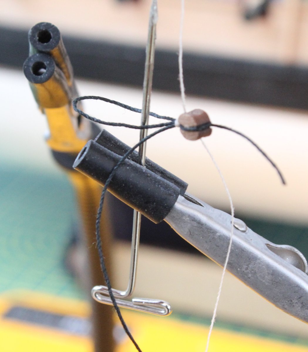
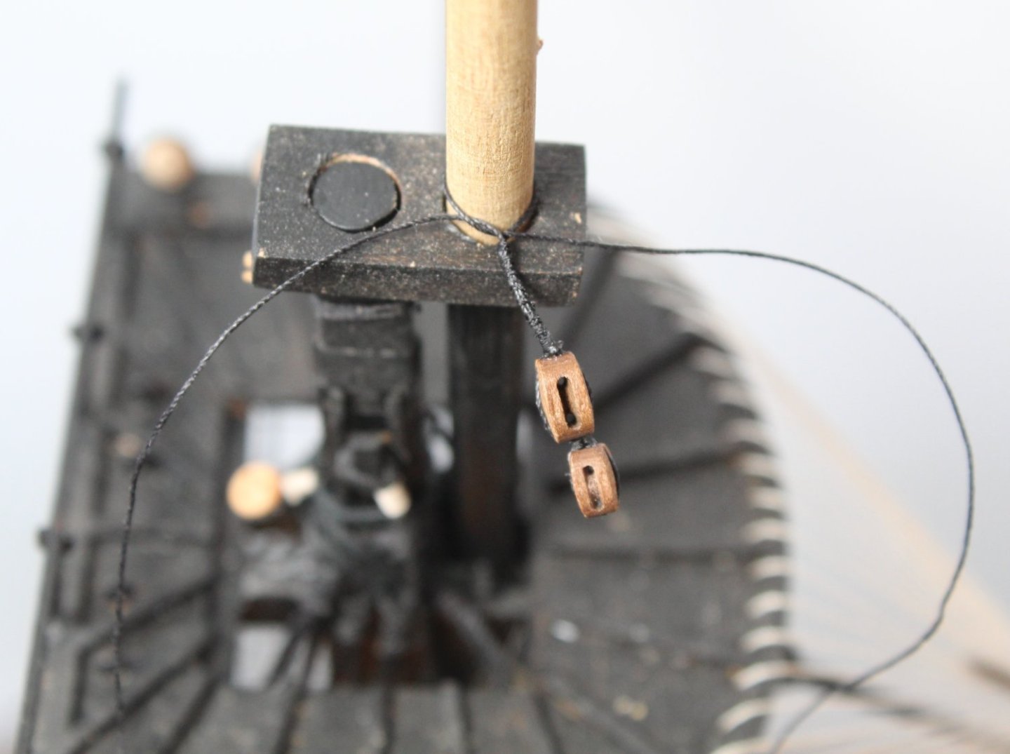
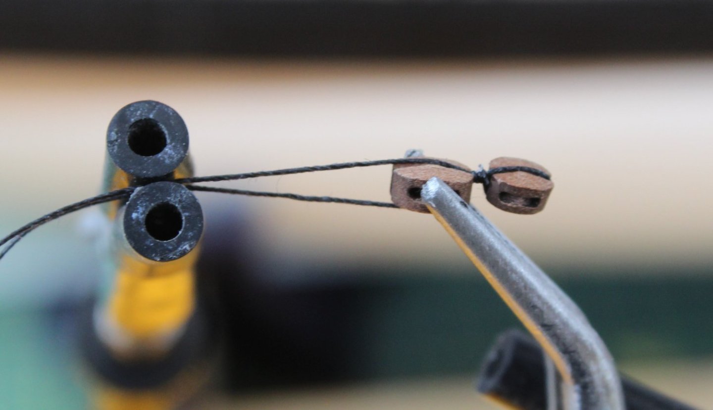
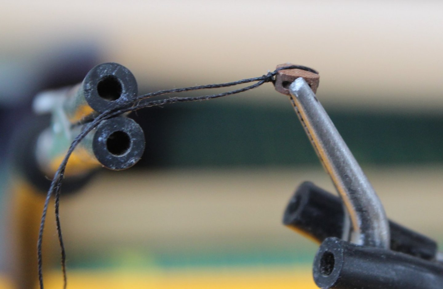
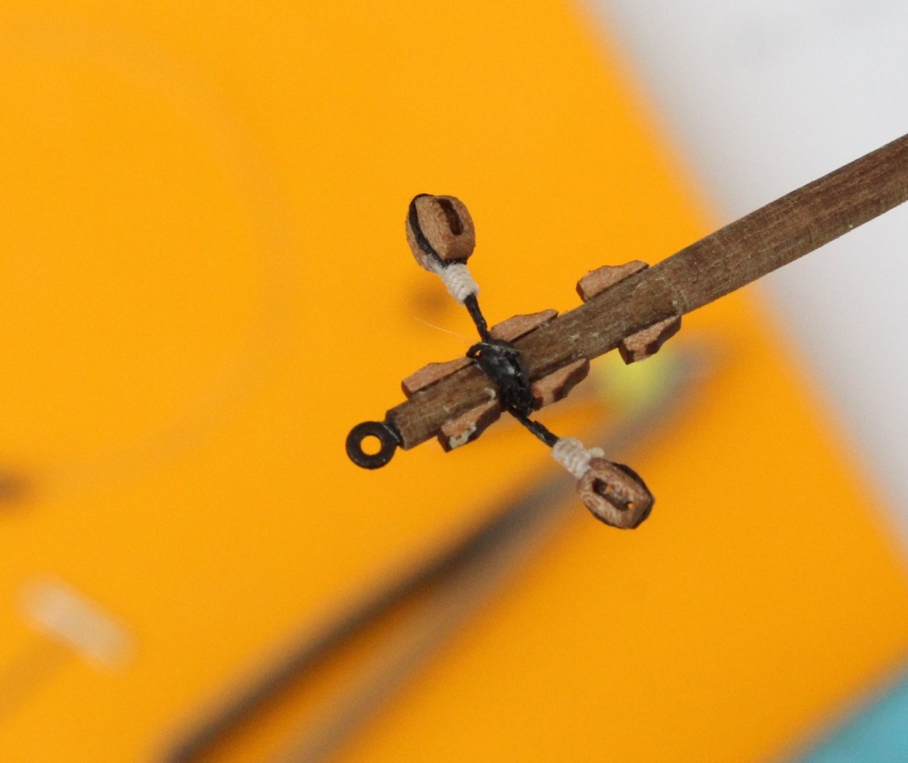
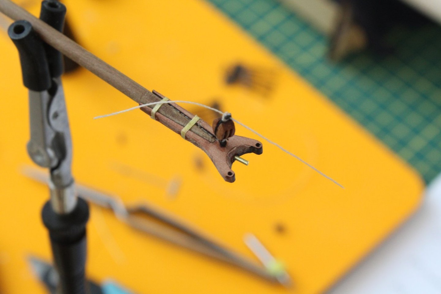
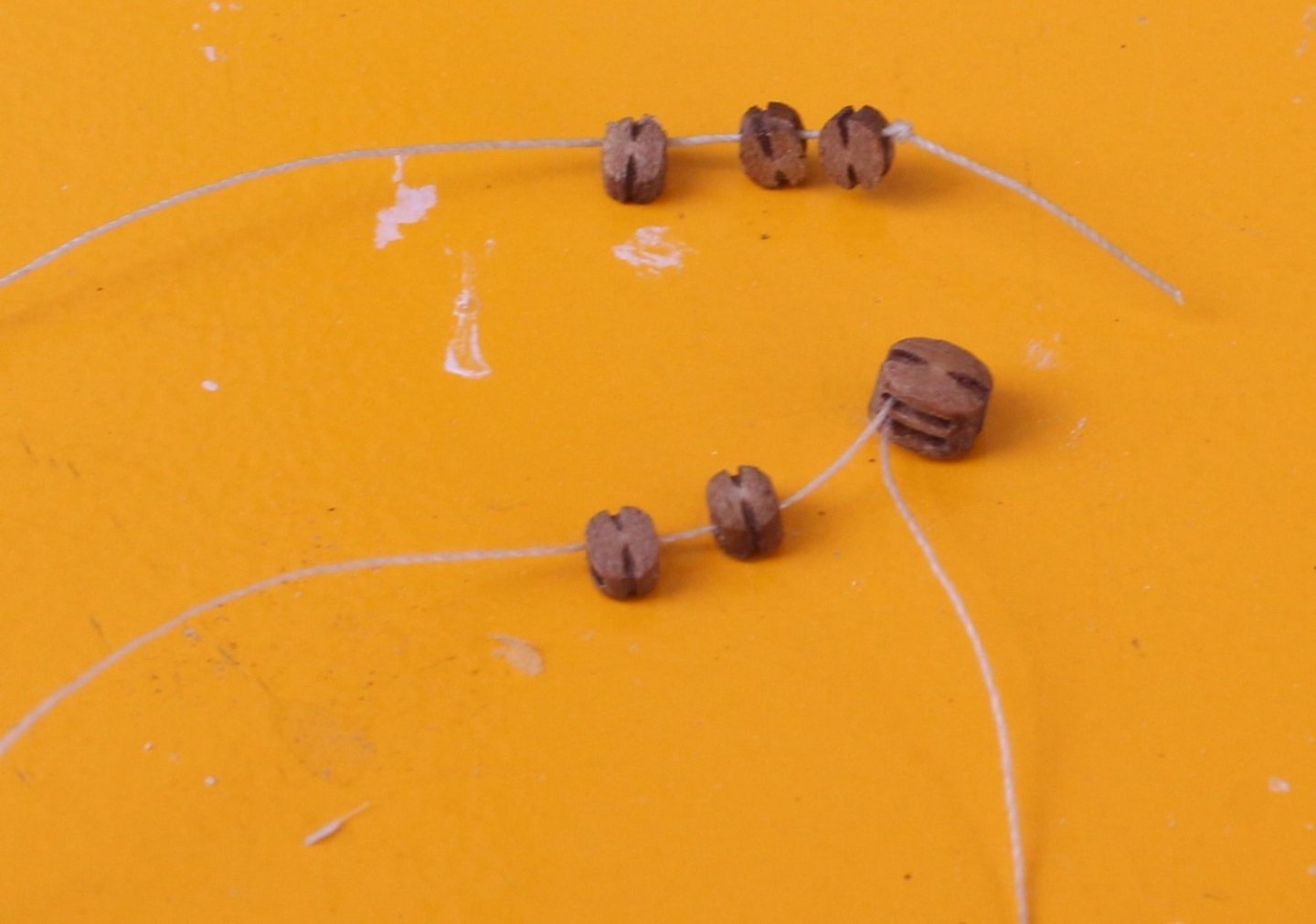
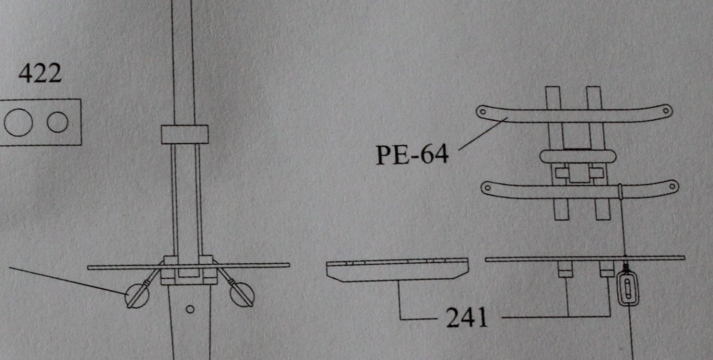
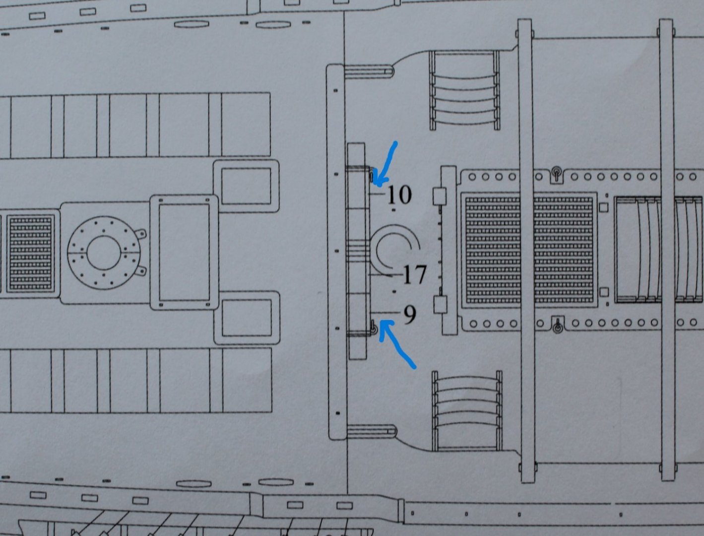
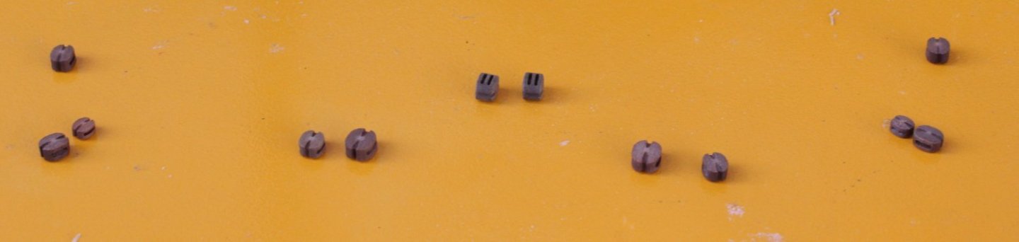
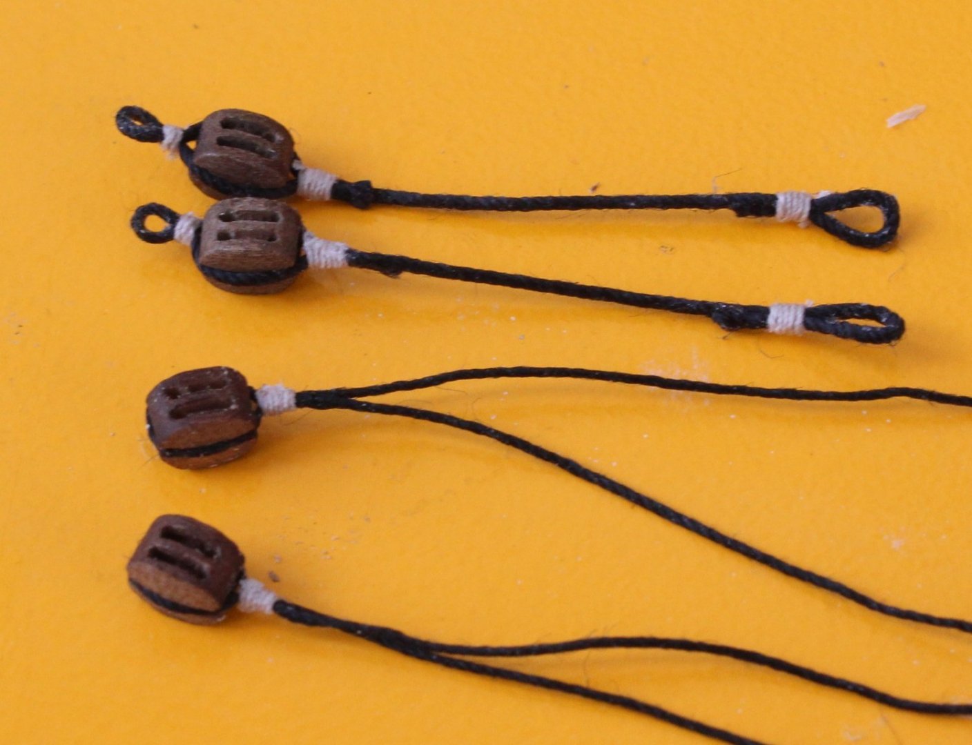
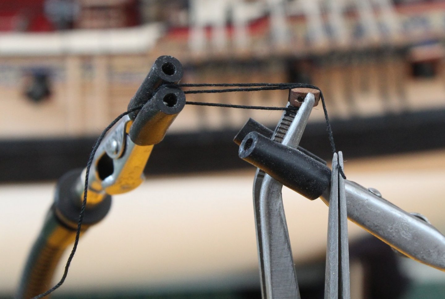
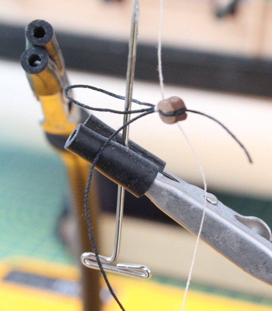
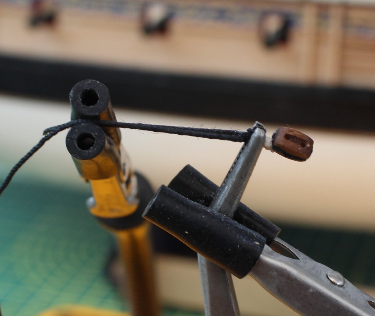
Main Yard Lift Double Block Manufacture I thought I would share the method I have used this morning to make the 2 off main yard lift double block assembly. These block assemblies are both fastened around the main topmast, sited just above the end cap. Each double block assembly comprises a 4mm and a 5mm single block. When checking the rigging plans I noted that 0.25mm natural thread will be used when these blocks are rigged with the double blocks located on each the end of main yard. The first task is to make sure the holes in the blocks will take the required thread therefore I run a suitably sized micro drill through the holes as can be seen in the photo below. Starting with a 4mm block I hold it in place using my quad hands. An approx. 20cm length of 0.25mm black thread is then wrapped around the block and the two free ends of the thread are held in place also with the quad hands. This arrangement is shown is the next photo. I decided to use some black flying tying thread for the seizing. For the seizing I am using a series of half hitch knots. The first one is place on the underside, the second is placed on the top side. In the picture below I am in the process of adding one to the top side. In total I add 4 off half hitch knots to the top and 4 off half hitch knots to the underside. Once the seizing is completed I add a touch of CA gel to the seizing and trim the excess thread. As can be seen in the photo below the seizing is not, as yet, tight up against the block. The seizing can be moved tight to the block by simply pull the two free thread ends in opposite directions. Next a 5mm block is held in the quad hands and the thread, complete with the 4mm block, is wrapped around the block. The free ends are the held in place with the quad hands. This arrangement is shown in the next photo. The 5mm block is then seized. I decided to use some 0.1mm natural thread for this. In the next photo I am in the process of adding the second half hitch knot to the top side. In total I added 4 off half hitch knots to the top and 4 off half hitch knots to the underside. After a touch of ca gel is applied to the seizing the excess thread is trimmed and the two free ends are pulled in opposite directions to ensure the seizing is tight against the 5mm block. After around 45 minutes of effort I have completed both double yard lift blocks for the main mast. The double block arrangement can then be added to the main top mast. I have made a trial fit, as can be seen in the photo below. I need to increase the distance between the 5mm block and the main top mast as it is clearly to close to the end cap. I have three option to solve this: a) Remove the 5mm block seizing and then redo with 0.1mm natural thread with around 10 off top and 10 off bottom half hitch knots. b) Leave the existing seizing in place and add a few more op and bottom half hitch knots, maybe using the fly tying black thread. c) Remove the 5mm block seizing and then redo with black fly tying thread with around 10 off top and 10 off bottom half hitch knots. I will probably try method b) first but I am tempted to revert to method c.


- 476 replies
-
- 7
-
-
- sphinx
- vanguard models
- (and 1 more)
-
Gaff Halliard After completing the mizzen topmast shrouds I decided to complete the Gaff Halliard rigging. This required two lengths (approx. 100mm) of 0.5mm black thread rigged to the end of the mizzen gaff. I then made up two 3mm single blocks with a thimble (eyelet) on each end. The two free ends of the black thread were attached, via the thimble, to their respective blocks. Two lengths of 0.1mm natural thread was then attached to the thimbles at the other end of the blocks. Next I seized to further 2 off 3mm single blocks, adding a rigging hook to one end of each block. The two rigging hooks were fed through the two outer most eyelets on the inner stern fascia panel. It was then a simple case of rigging the 0.1mm natural thread from the upper blocks through the lower blocks and then back up and through the top blocks before being belayed to the outer most cleats on the inner stern fascia panel. Next I will making up and securing the main and fore mast double yard brace block assemblies. Once that is done I plan to add the main and fore top mast shrouds lines


- 476 replies
-
- 6
-
-
- sphinx
- vanguard models
- (and 1 more)
-
I did find the Amati clips a useful tool when I was doing the first planking.
- 426 replies
-
- 2
-
-
- Vanguard Models
- Sphinx
- (and 1 more)
-
Mizzen Top Shrouds - WIP Work has been slow on the Sphinx build over the last few days as the weather has been really nice so I have been spending some time in the garden. We have also spent time looking after our grandchildren which is always fun. I have now added the two crossjack lift blocks to the mizzen top mast, which are shown in the top right hand corner of the picture below. I have also started to add the mizzen topmast shrouds. The starboard side is complete and the lanyards just need tying off. When looking at the following picture I have just noticed that the rear deadeye strop has broken free and is not now flush with the platform. This is a tad frustrating but I am not planning to remove the shroud, reseat the strop and to then redo the shroud line as this may also impact of the futtock shroud rigging. I am also reasonable happy with the alignment of the shroud deadeyes. As can seen in the next picture I only have one shroud left to do on the port side. The final shroud line has been fitted and just need to have the deadeye and lanyards adding.

- 476 replies
-
- 4
-
-
- sphinx
- vanguard models
- (and 1 more)
-
Nicely done, she looks great
-
It is a great kit and well worth the expenditure when funds are available.
- 476 replies
-
- 3
-
-
- sphinx
- vanguard models
- (and 1 more)
-
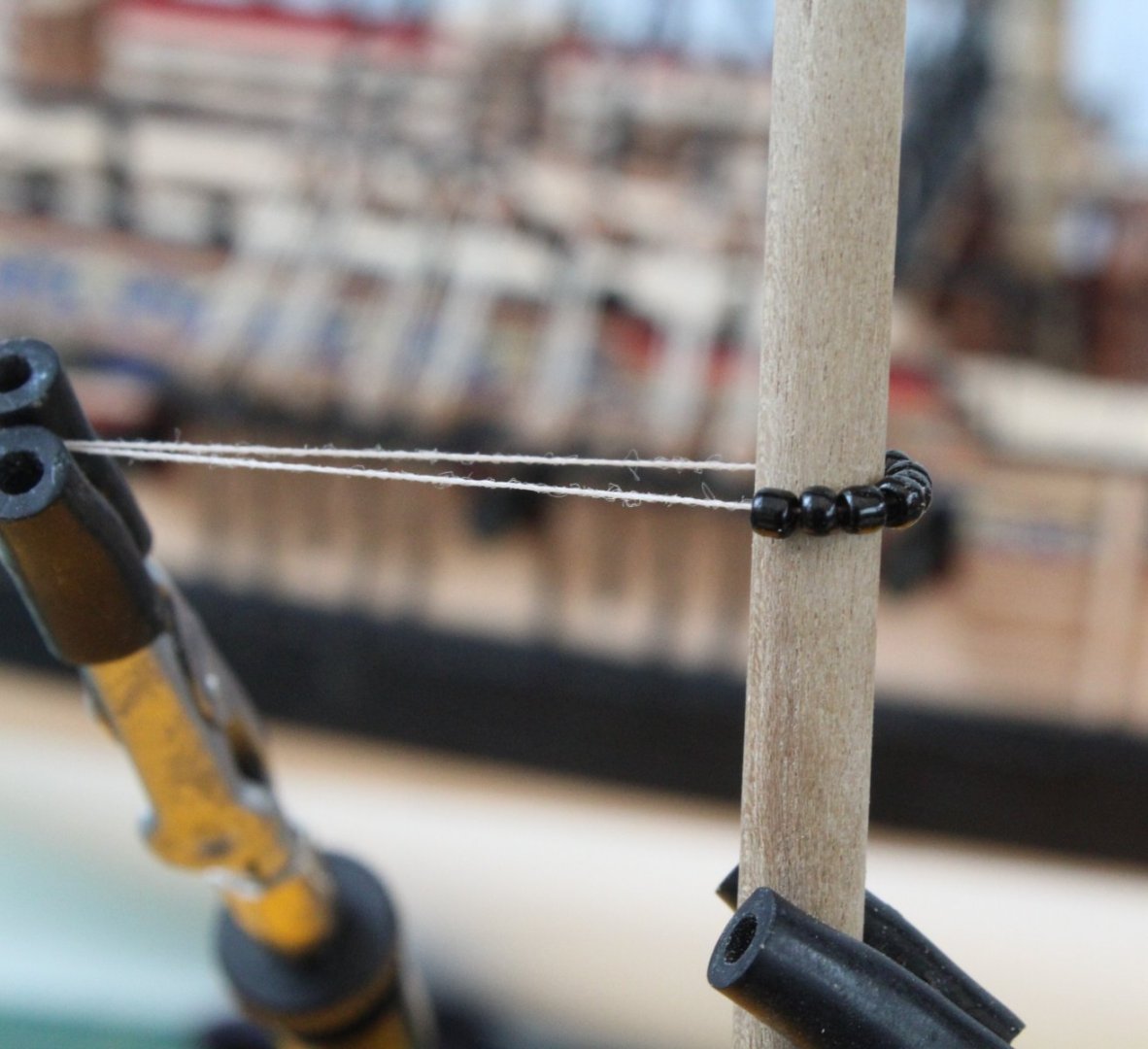
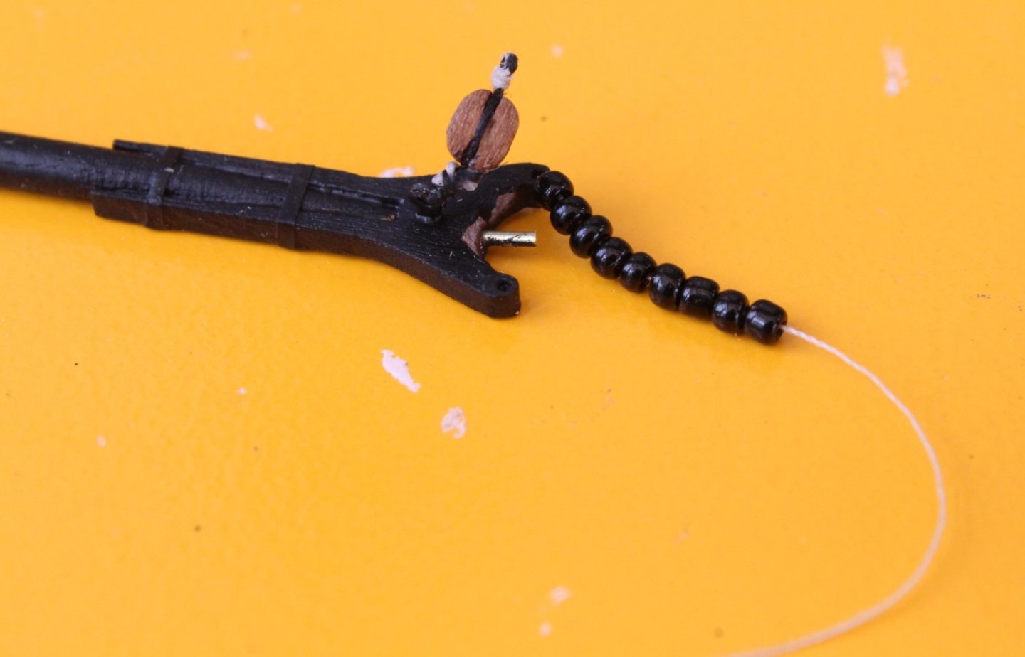
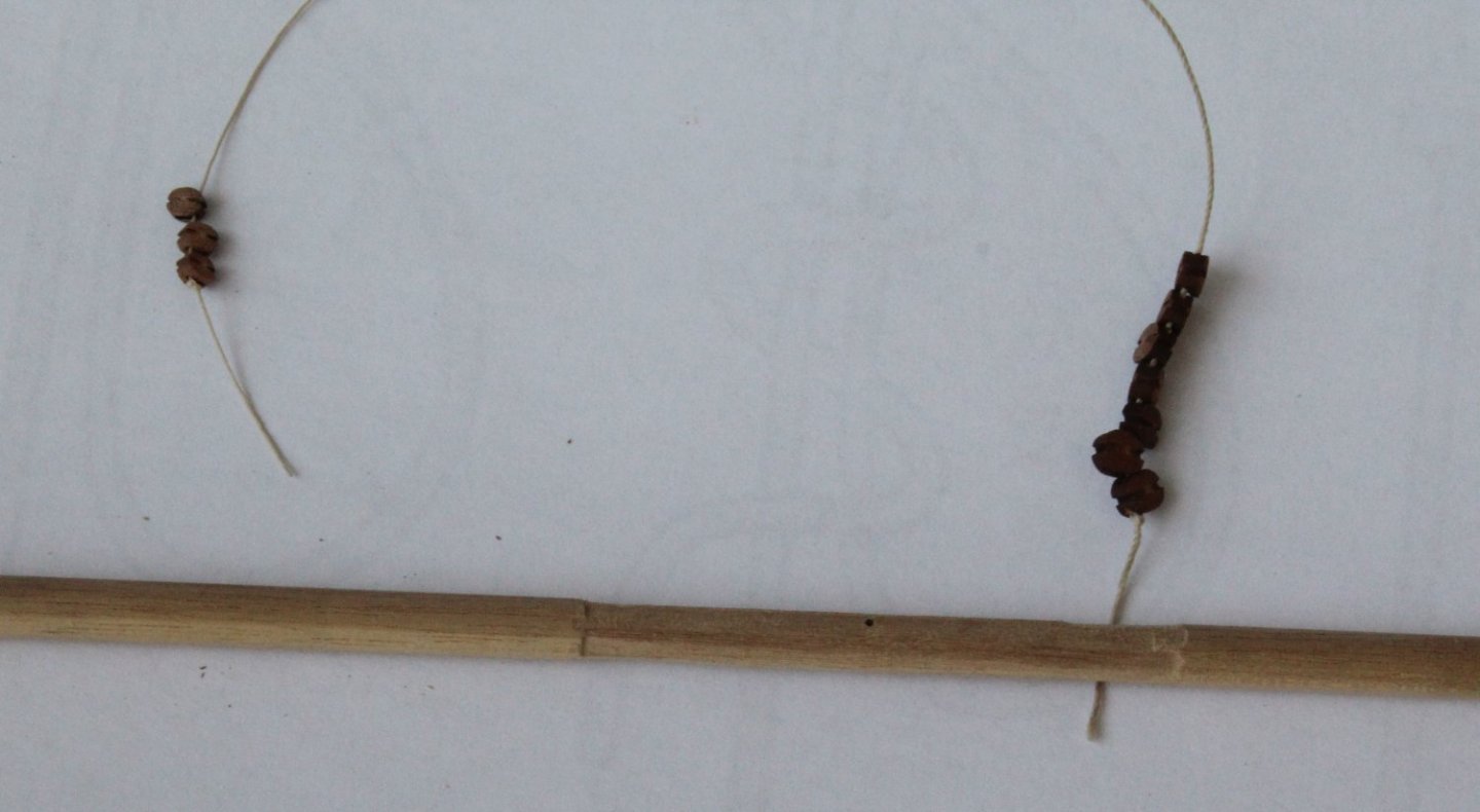
Mizzen Gaff Parrel Beads / Trucks Today's task was to fasten the mizzen gaff to the mizzen mast. In theory this was going to be an fairly straightforward activity but maybe a tad fiddly. Many thanks to @James H, @DelF and @Blue Ensign for their help and guidance. Of course I managed to make this a far more complicated task with a few mistakes which really tested my patience. I am not sure of the correct technical term, parrel beads or parrel trucks. I will stick with parrel beads. With a short length dowel held in the quad hands I placed a number of parrel beads on some thread to see how many would be required. I decided that I would need 9 x parrel beads. This arrangement is shown in the photo below. I then fed a length of 0.1mm natural thread from the underside of the mizzen gaff yolk. I added a knot to the end of the thread to stop it coming through the yolk. I then added 9 parrel beads to the thread, as shown in the next photo. I applied a coating of wood glue to the jaws of the mizzen gaff yolk and then added it to the mizzen mast. The pin held the mizzen gaff in place. The free end of the parrel bead thread was fed back through the other hole in the yolk and was held under tension with a clamp. The tensioned thread can be seen in the next photo. Using a tip from @Blue Ensign I added a length of thread to the other end of the mizzen gaff to help hold it at the required angle. The next photo shows the clamping arrangement. The red clamp is holding the parrel bead thread in place and the reverse action tweezers hanging beneath the main mast platform is holding the other thread under tension. Once I allowed time for the glue to cure the clamps were removed. I then added a slip knot to the parrel bead thread end and pulled it tight up to the underside of the mizzen gaff yolk. I then added the jeer thread to the timble on mizzen gaff as shown below. Everything was coming together nicely. As I started to feed the jeer thread through the two blocks I realised there was a problem. The plan sheet indicated that a 4mm double block was required for the jeer block on the mizzen gaff. However this only needed to be a single block. I decided to leave the double block in place and completed the jeer rigging. I was happy with the end result however disaster struck when I trimmed some of the excess thread as I managed to cut through one of the jeer rigging lines. Therefore I took the decision to remove the jeer and parrel bead rigging and to release the mizzen gaff from the mizzen mast. I was then able to replace the 4mm double block with a 4mm single block. After a couple more hours I had completed the rework. The next photo shows the completed jeer rigging. The next photo shows the jeer rigging belayed. Next I moved on to adding the gaff halliard rigging. This was straightforward task. The gaff halliard rigging is shown in the next photo. I have not belayed the free end which will be done once the correct tension has been applied.

- 476 replies
-
- 11
-
-
- sphinx
- vanguard models
- (and 1 more)
-
Hello Allan Many thanks for your comments. The belaying pins are supplied with the kit. I know from other discussions I have seen on MSW Chris's belaying pins are more representative to scale compared with some of the more robust looking belaying pins supplied by other kit manufacturers. I am not sure which thread Chris uses but I know some is from Guttermann. Glenn
- 476 replies
-
- 3
-
-
- sphinx
- vanguard models
- (and 1 more)
-
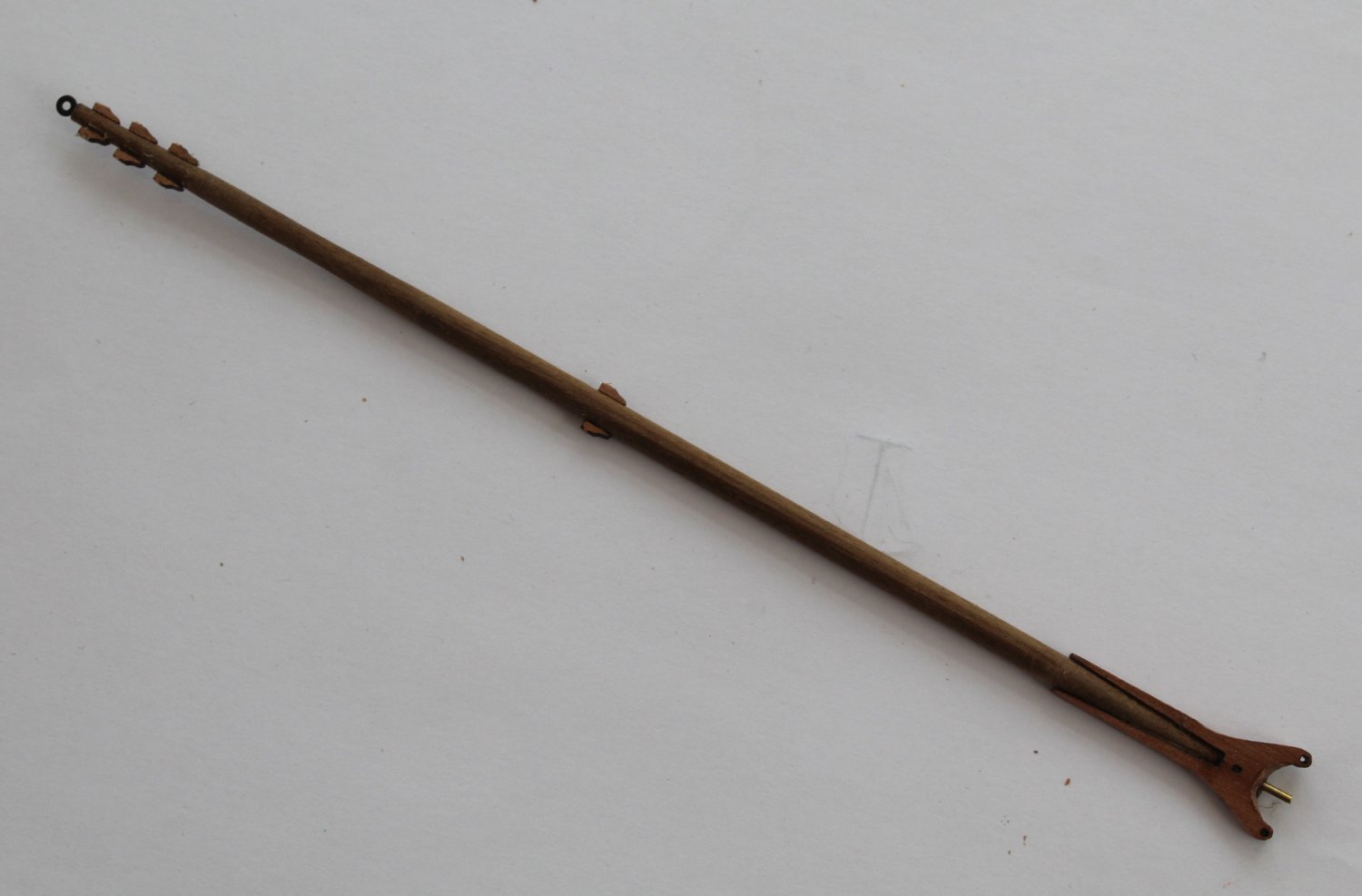
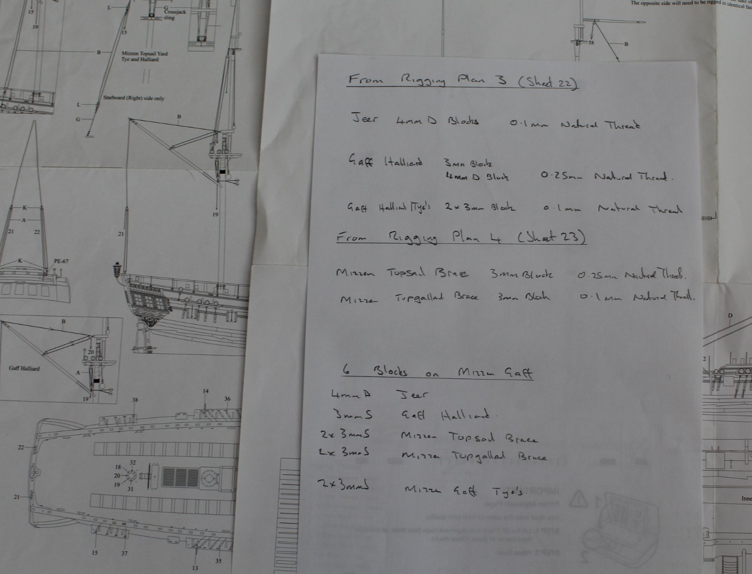
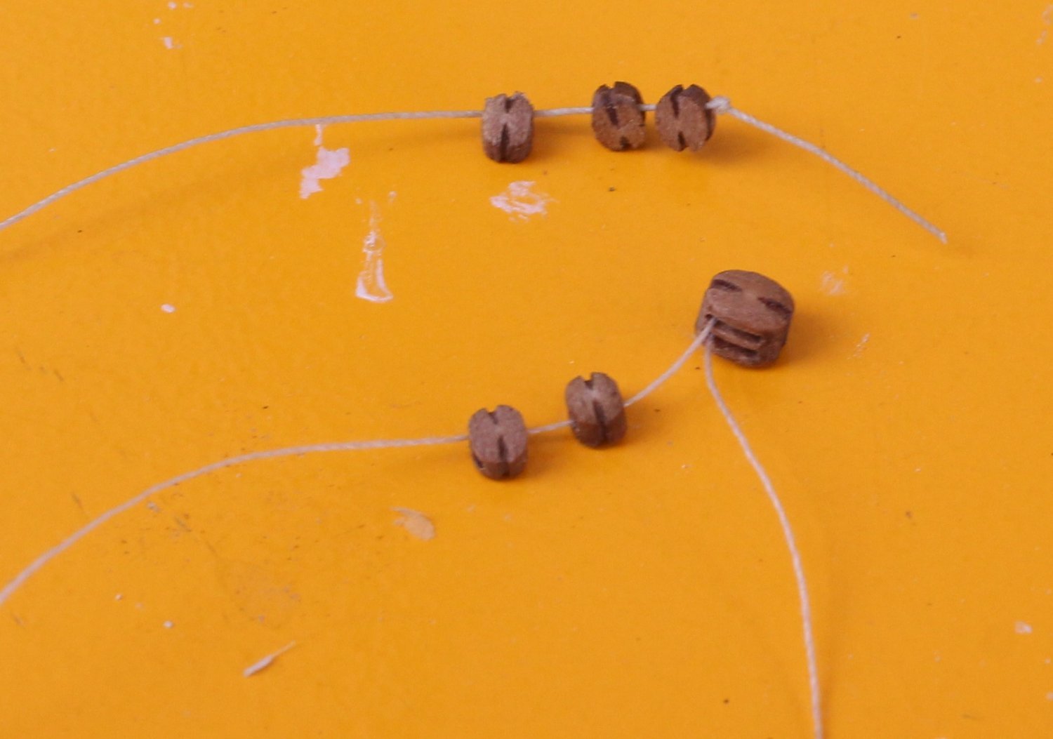
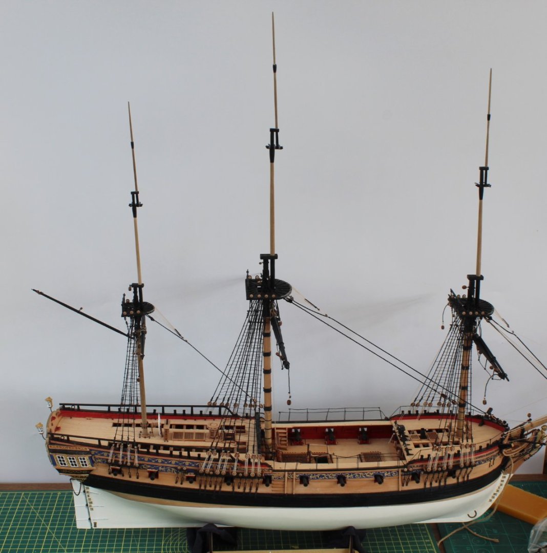
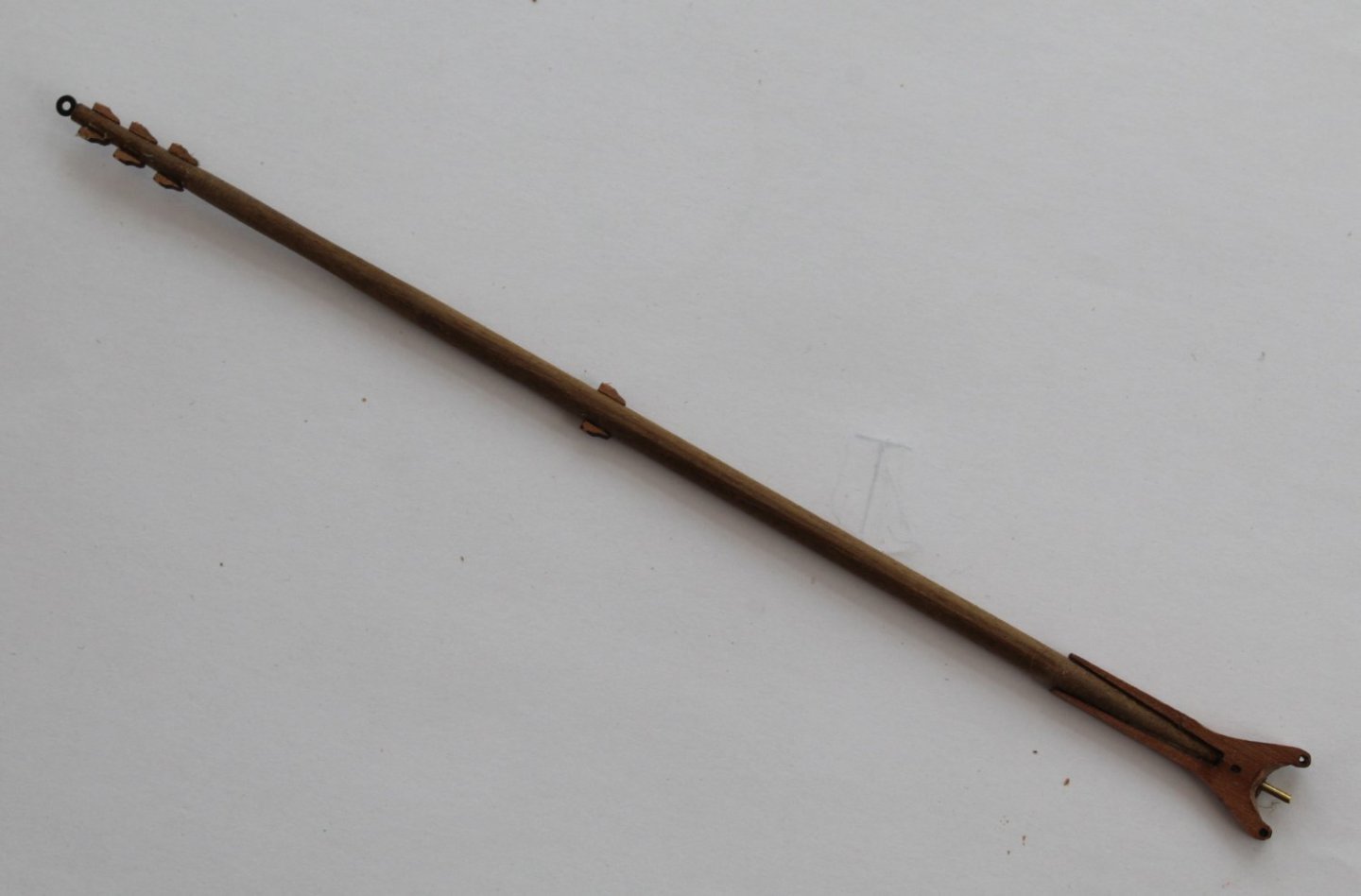
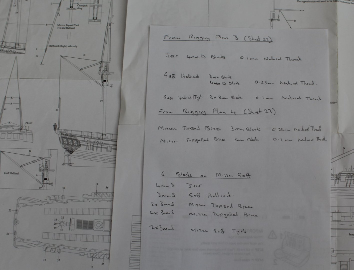
Mizzen Gaff When deciding on the next build task I realised I had not made the mizzen gaff. The mizzen gaff started life as a length of 3mm down. One end required a taper down to 1.8mm and is fitted with an eyebolt. The other end required a taper down to 1.5mm for the yolk. The yolk has a sanding line to allow a chamfer to be added so the mizzen gaff will sit at the right angle. I did add a pin, suitably angled, which will hold the mizzen gaff in place. There are also 8 cleats required which have been added. The picture below shows the completion of the first stage of the build process. The next picture shows a test fit of the mizzen gaff. There are a number of blocks to be added to the mizzen gaff. As per part of my normal build process I made a set of notes showing the blocks required and the rigging thread required, as can be seen in the next picture. As always I like to check the rigging thread will pass through the blocks. The top three blocks in the picture below are 3mm single blocks on a length of 0.25mm natural thread. The bottom three blocks (2 x 3mm single and 1 x 4mm double) are on a length of 0.1mm natural thread The next picture shows the mizzen gaff being held in the quad hands. The 4mm double jeer block and the two mizzen top gallant braces have been added. I also used two strips of 1mm yellow tape for the banding around the yolk. The next picture is simply a close up of the two mizzen top gallant braces And a close up of the The 4mm double jeer block. You will note I have a small length of thread in the thimble on this block, which was done to make sure the thread could be threaded. Next I added the gaff halliard block, as shown below. A clove hitch knot was used to secure the gaff halliard block to the mizzen gaff. Finally the two blocks for the mizzen topsail braces were added. The completed mizzen gaff was then painted black and test fitted once again to the mizzen mast. I just have to add the parrel beads and the job will be completed.


- 476 replies
-
- 5
-
-
- sphinx
- vanguard models
- (and 1 more)
-
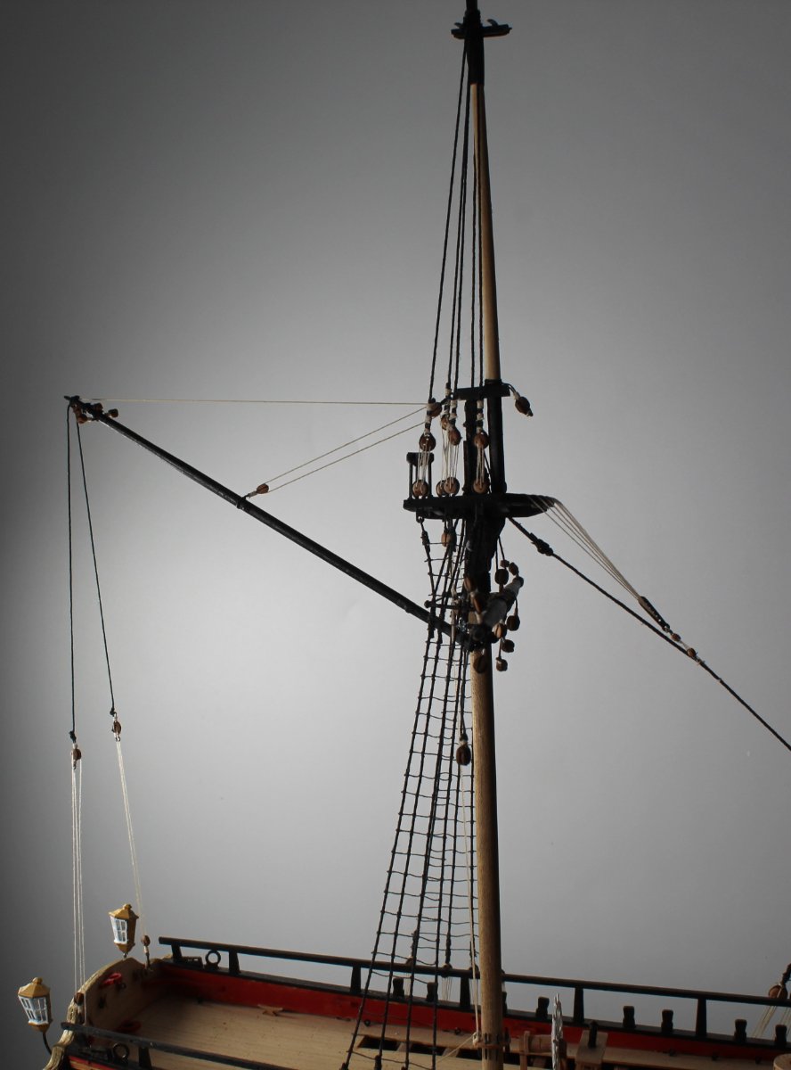
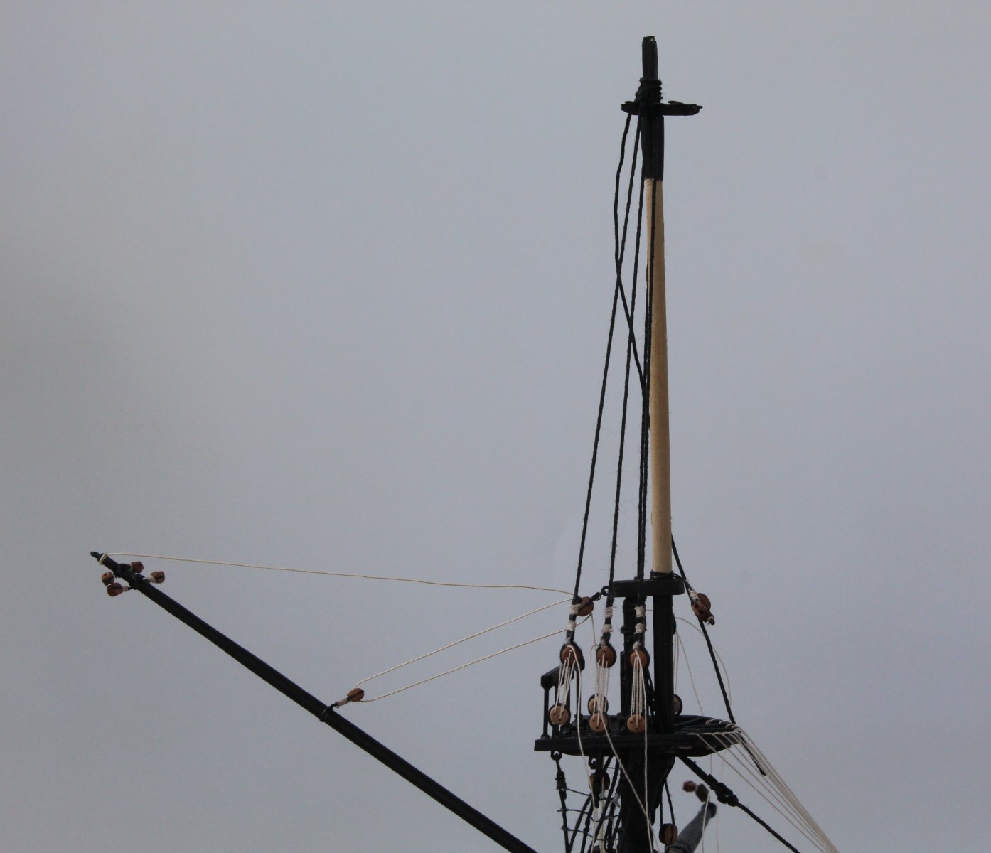
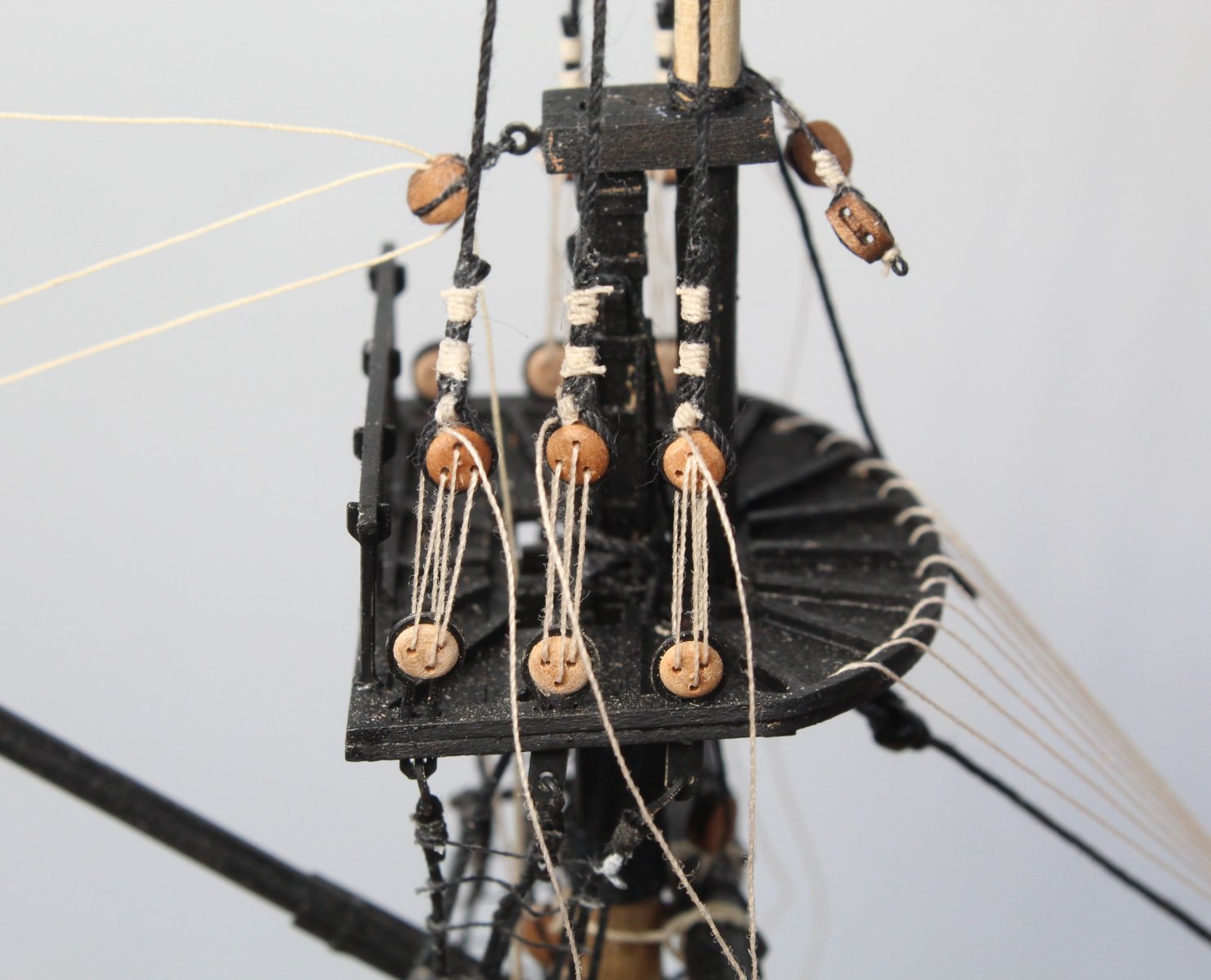
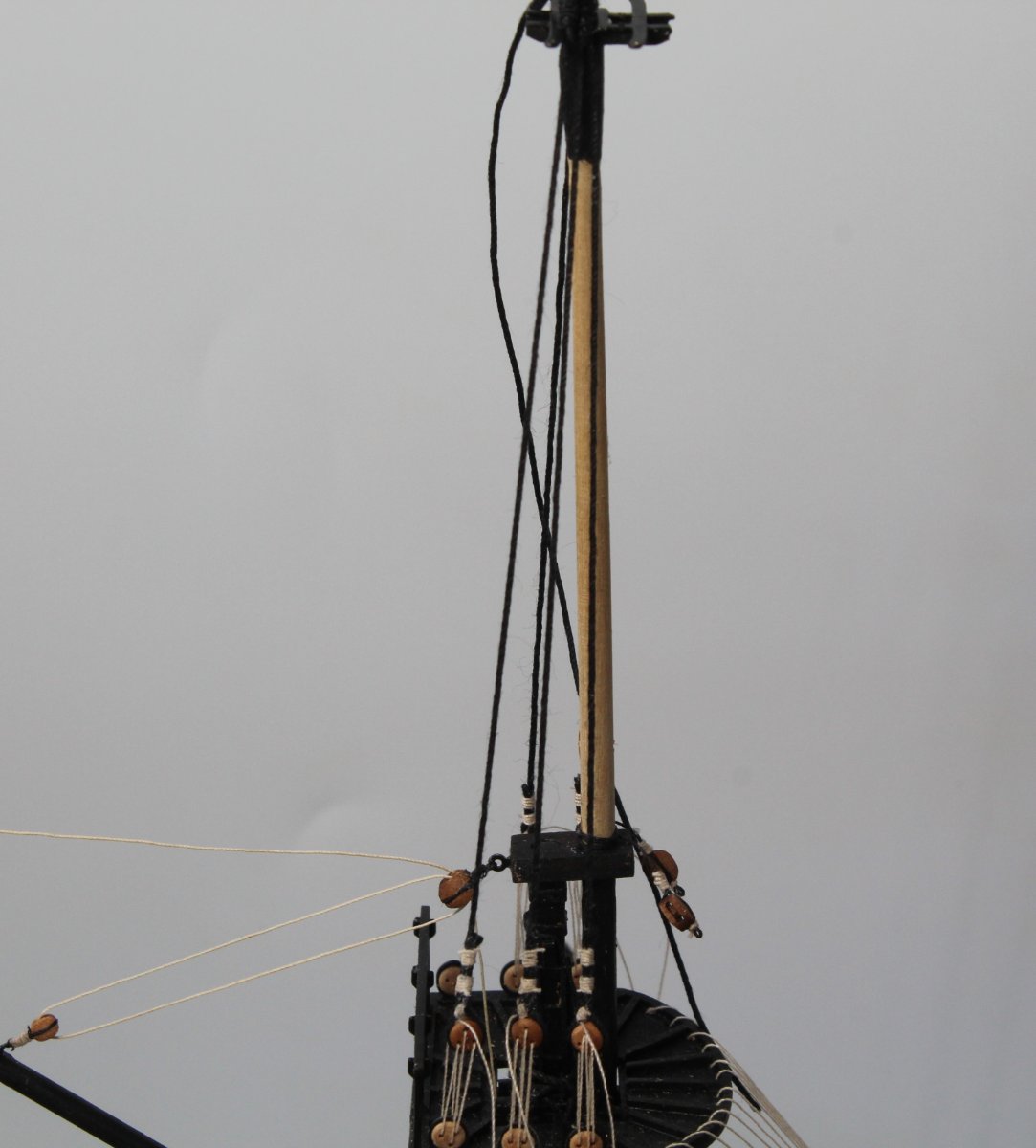
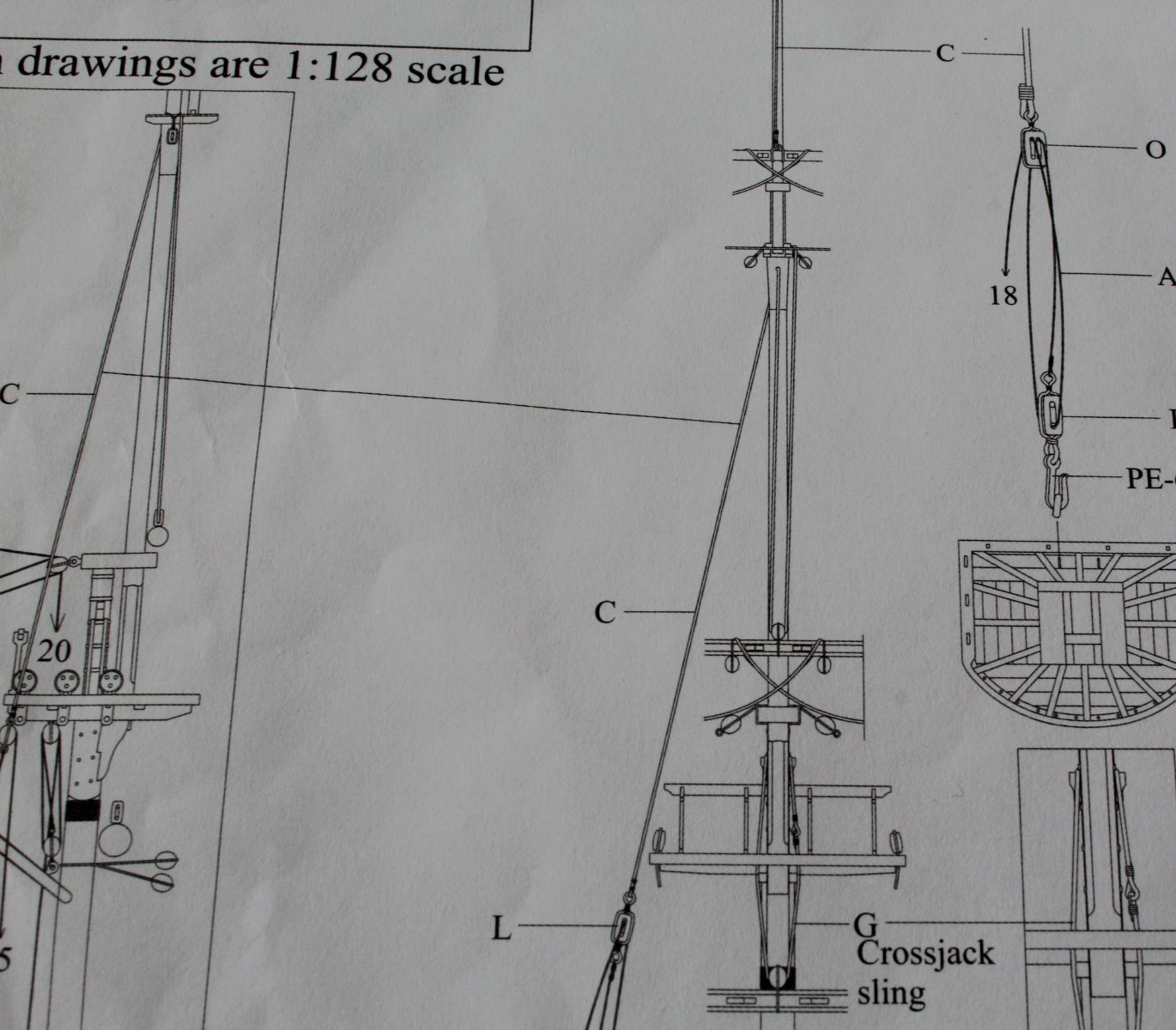
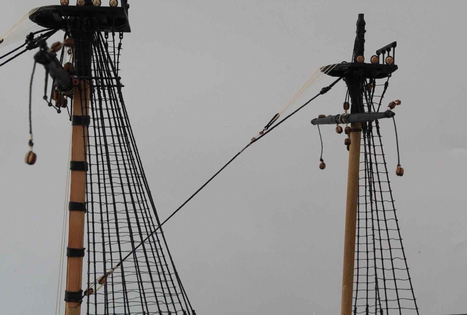
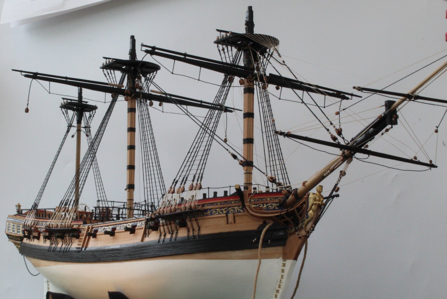
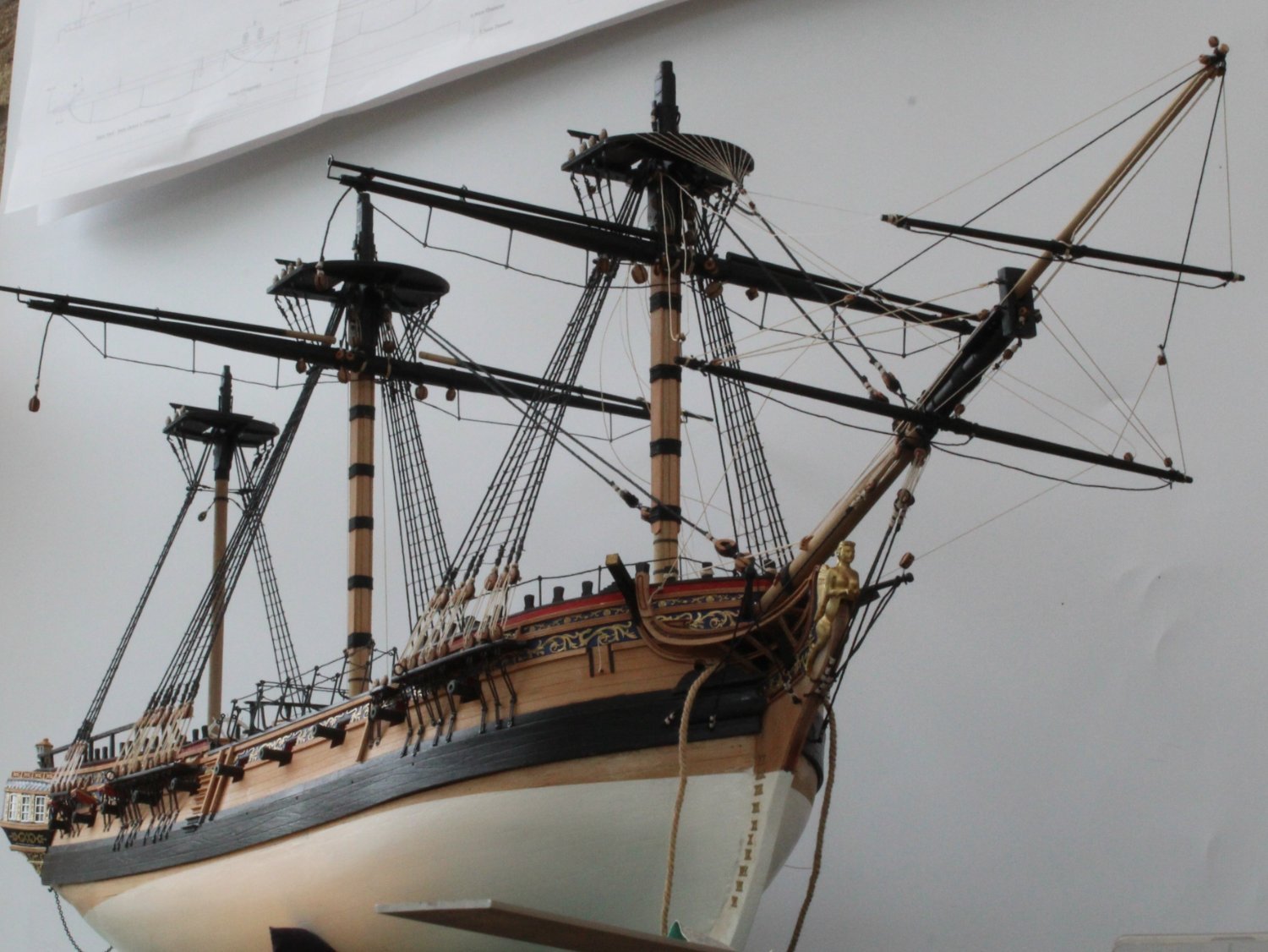
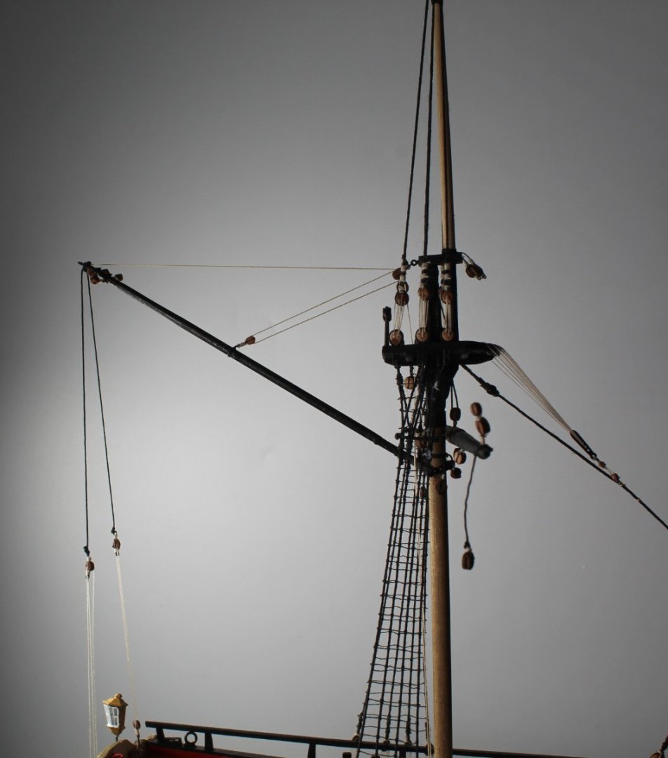
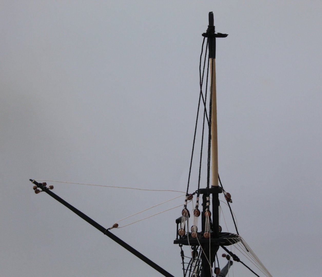
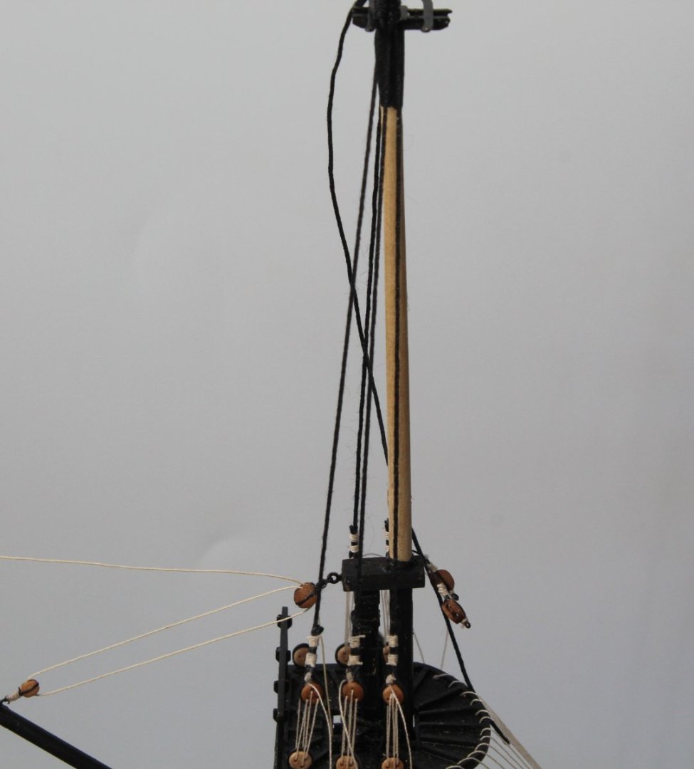
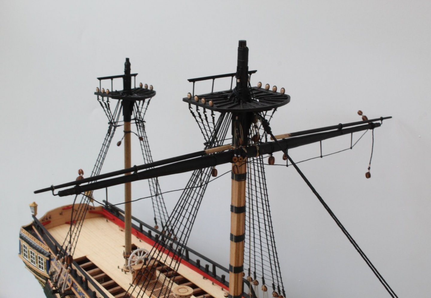
Top and Topgallant Masts Over the last couple of days I have been working on top and topgallant masts. I spent a bit of time checking the masts would fit through the caps. Once I was happy with that I then checked the FID's could be slotted in. The upper platforms were glued to the topmasts. Once that was done it was a case of painting the various mast sections and end caps black. In the following two pictures the top and topgallant masts have fitted to the Sphinx, but they have are not glued in place. I have started in seize the various blocks required for the top and topgallant masts so they can be added as and when required during the rigging process. I have been studying the rigging plans and the next logical step would be to add the shrouds, lanyards and ratlines for the topmasts. I may decide add the braces for the main, fore and mizzen yards before that however as I do like to work from bottom to top. I also like to check the rigging thread size required for a block can be fed through the hole before it is seized. When a thread does not seem to fed through the block hole I will run a suitably sized micro drill through which does the trick. Mizzen Topsail Tye's When checking the rigging plans I noted there are two blocks required for mizzen, main and fore topsail yard tye's. These blocks which are fastened to the topmast crosstrees which are on shown the right hand side of the picture below (mizzen mast with only one of the two blocks shown). However when looking at the rigging for the mizzen topsail yard tye's, as shown in the next photo it would appear the thread is fastened to the crosstrees and then fed through the block on the mizzen topsail yard and then taken back up and fed through the hole in the mizzen topmast and then taken down to be belayed via another double block arrangement. Therefore the mizzen topsail tye's blocks seem to be redundant. Both the fore and main topsail tye's are rigged through blocks fastened to the crosstrees.
- 476 replies
-
- 5
-
-

-
- sphinx
- vanguard models
- (and 1 more)
-
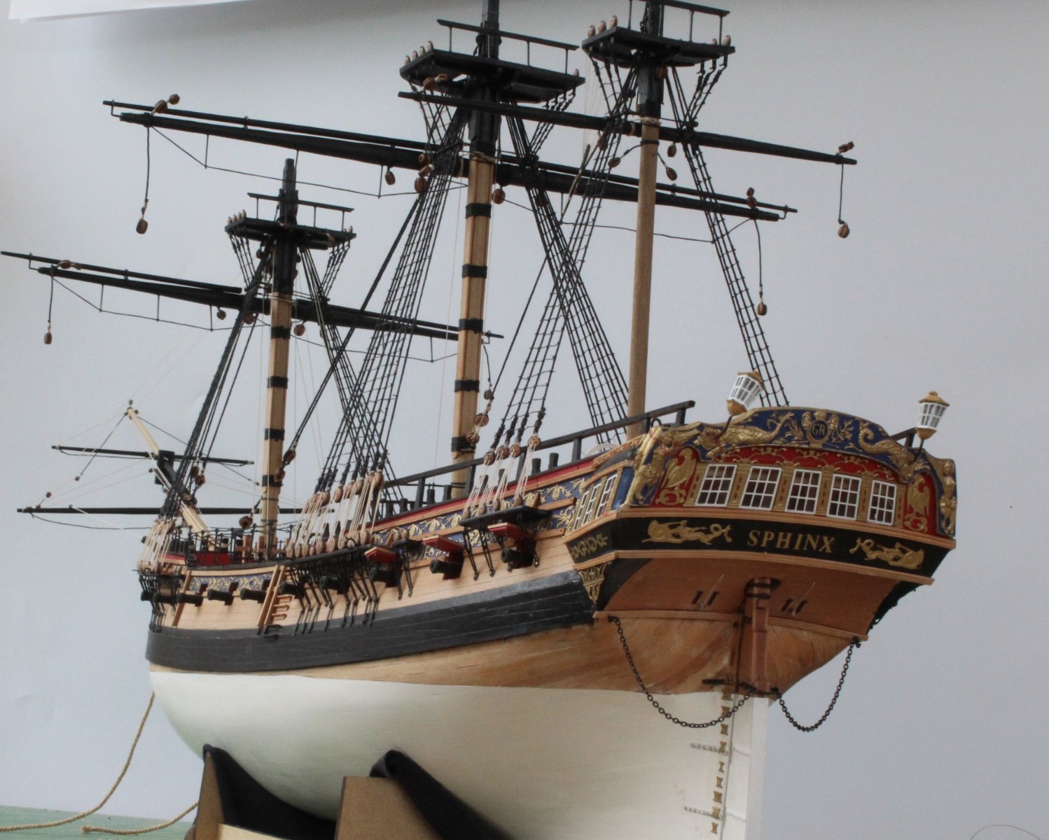
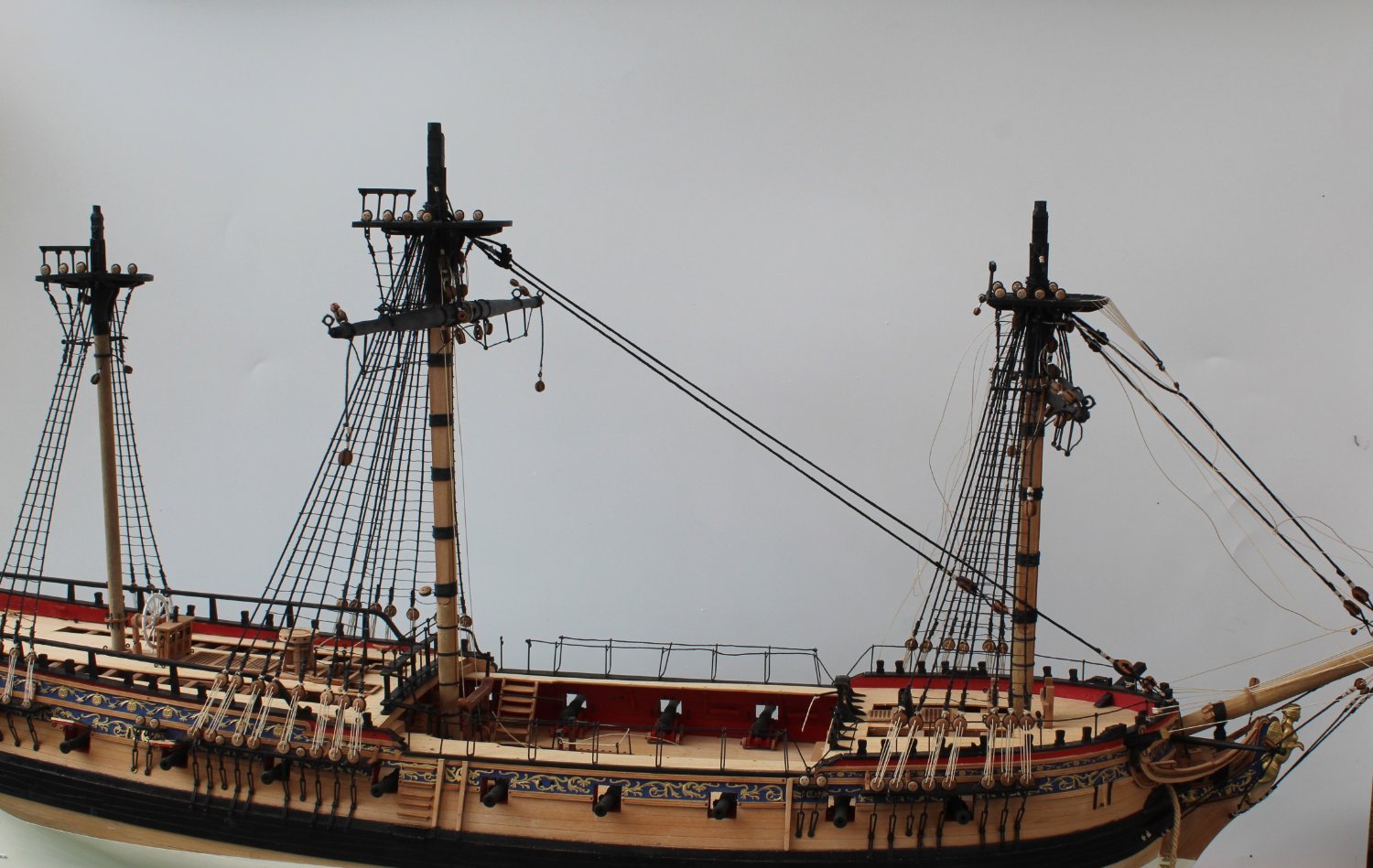
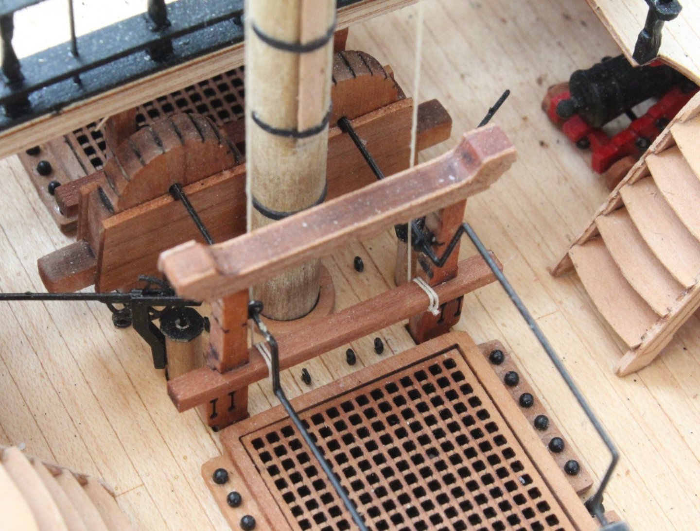
Crossjack Yard Completed, Foremast Jeers & Spritsail Braces Belayed Work is now complete with the installation of the Crossjack yard on to the Mizzen mast. The first task was to add the truss pendant using the same method as detailed in previous posts as can be seen in the picture below. After the truss pendants were fitted I added the stay. I forgot to take a picture before I added the crowsfeet, but I did take one after. I then added the crossjack sling. The crossjack sling is a length of black thread which has a thimble eyelet on one end. The thread is looped around the top of the mizzen mast and held in place by two cleats. The free end is then fed through a block on the crossjack yard before it is fed through the thimble and seized to complete the loop. I have taken a photo of the sling in place which is shown below. The final task was to add the crowsfeet. I am reasonably happy with how they look and I have made a much better job compared with both the fore and main mast. Before moving on to adding the topmasts I decided I should belay the foremast jeers and spritsail yard braces. The jeers were carefully taken down to the deck level and after checking the rigging plans were belayed the the fore bitts crossbeam. The spritsail and top spritsail yard braces are belayed to the belaying pins located on the forecastle breast beam rails. The next picture shows both the jeers and braces belayed. And to complete this post another picture of the Sphinx, noting I have a wonky starboard lantern.


- 476 replies
-
- 6
-
-
- sphinx
- vanguard models
- (and 1 more)
-
Thanks, slow and steady at the moment. I am pleased with the build so far. It is far from perfect but so much better than my previous builds. Still a few more weeks work ahead. I am thinking about building Erycina next.
- 476 replies
-
- 3
-
-
- sphinx
- vanguard models
- (and 1 more)
-
Mizzen Mast Crossjack Yard WIP The crossjack yard was fairly easy to taper in my mini lathe especially when using my recently acquired set of Proxxon wood turning chisels. The yard started life as a length of 5mm dowel. I started by making the octagonal central section. This was done using a mini file to create the various flat edges. Once that was done I moved on to the tapering each end down to 1.8mm which did not take too long at all. With the crossjack yard nicely tapered I added the 6 cleats. I also drilled a hole and added the supporting pin. It was now time to add the various blocks. I started with the crossjack yard lift block which, once seized, was attached to the crossyard yard using a clove hitch knot, which ran either side of the brass pin. Next I added the two jeer blocks. As with the lift block the two jeer blocks were secured to the crossjack yard with clove hitch knots. The two sheet / tack blocks were then added to each end of the yard. Each sheet / tack block arrangement comprised a 4mm single and a 3mm block which were seized together and then secured to the yard using a clove hitch knot. All that is left is to add the two brace blocks and to then paint the yard black which will be done tomorrow morning. The following two pictures shows the crossyard jack in position on the mizzen mast. I really like the first picture. I also took a few pictures of the Sphinx. After reviewing the various pictures taken, most of which were deleted, I could not decide which one of the remaining two to include in this post. In the end I decided to add them both.


- 476 replies
-
- 10
-
-
-
- sphinx
- vanguard models
- (and 1 more)
-
Main Stays, Jeers, Crows Feet The first task this morning was to add the lanyards for the main and preventor stays. For some reason I really struggled with the preventor stay lanyards. I should have added a few more turns therefore the end result is not brilliant but I can live with it. When I started work on the main stay I realised I had made an error with the position of both stays over the main mast. I managed to sort it out with a bit of fiddling and then added the lanyards. The completed stays look Ok. I then moved on to belay the main yard jeers. This was quite an easy task to complete. I adjusted the rigging between the blocks and then belayed to the bitts on the gallows. Once I was happy with the rigging of the jeers I completed the belaying process and trimmed the excess thread. As it was time for lunch I thought I would take a few pictures of the current state of play. The first one shows the main yard with the stunsail boom yards in place. I do need to finish painting both the stunsail booms black. I thought I would try an upward looking picture of the Sphinx and I really like how it turned out with the next two photos. After lunch I started work on the main mast crows feet which did not turn out too bad. Tomorrow I will turn my attention to manufacture of the crossjack yard for the mizzen mast. I have already made a start with the central octagonal section. I have also checked and made sure the different threads will pass thought the crossjack yard blocks.


- 476 replies
-
- 6
-
-
- sphinx
- vanguard models
- (and 1 more)
-
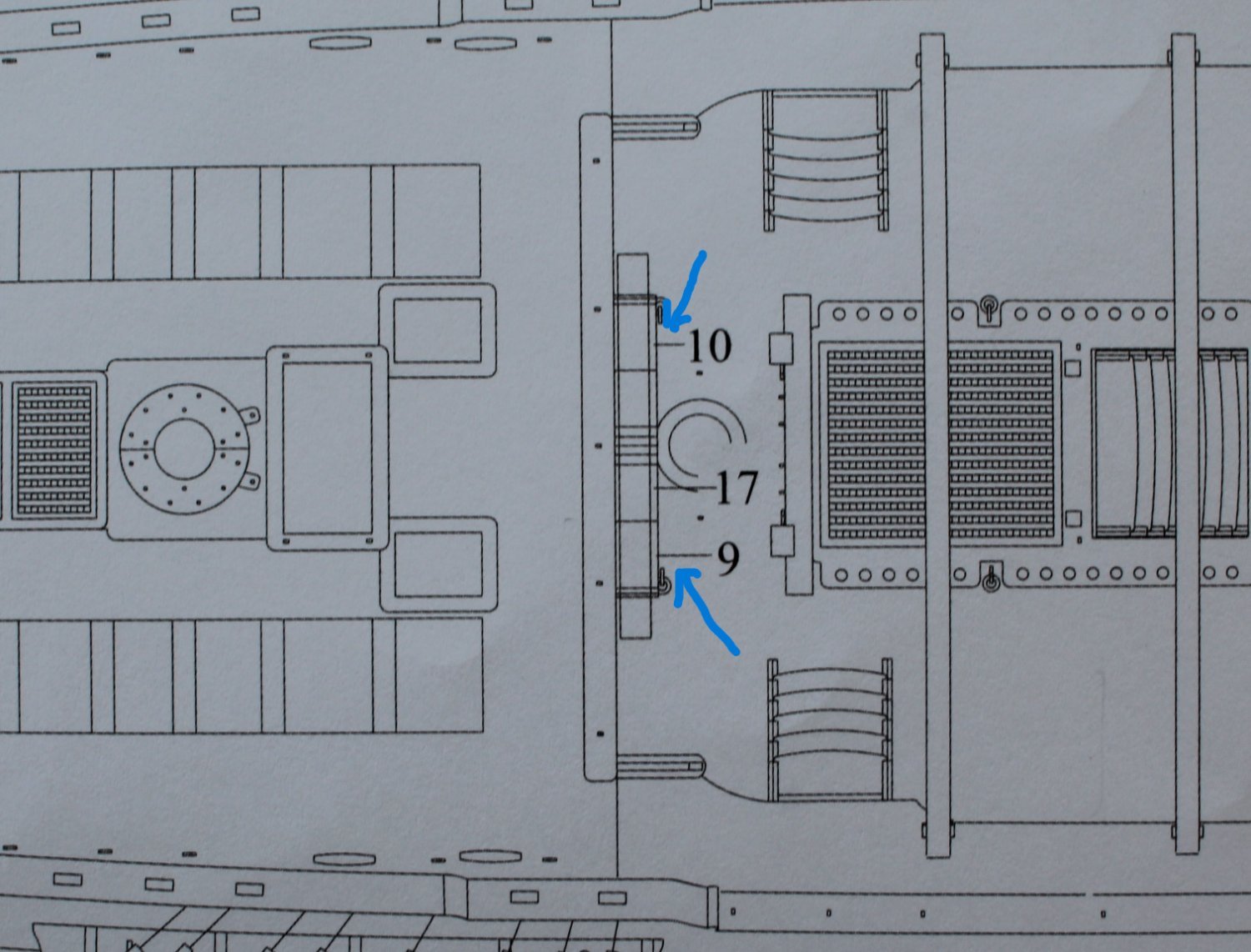
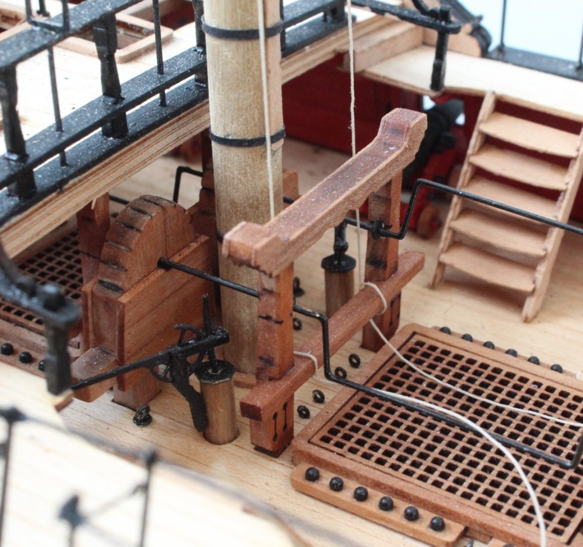
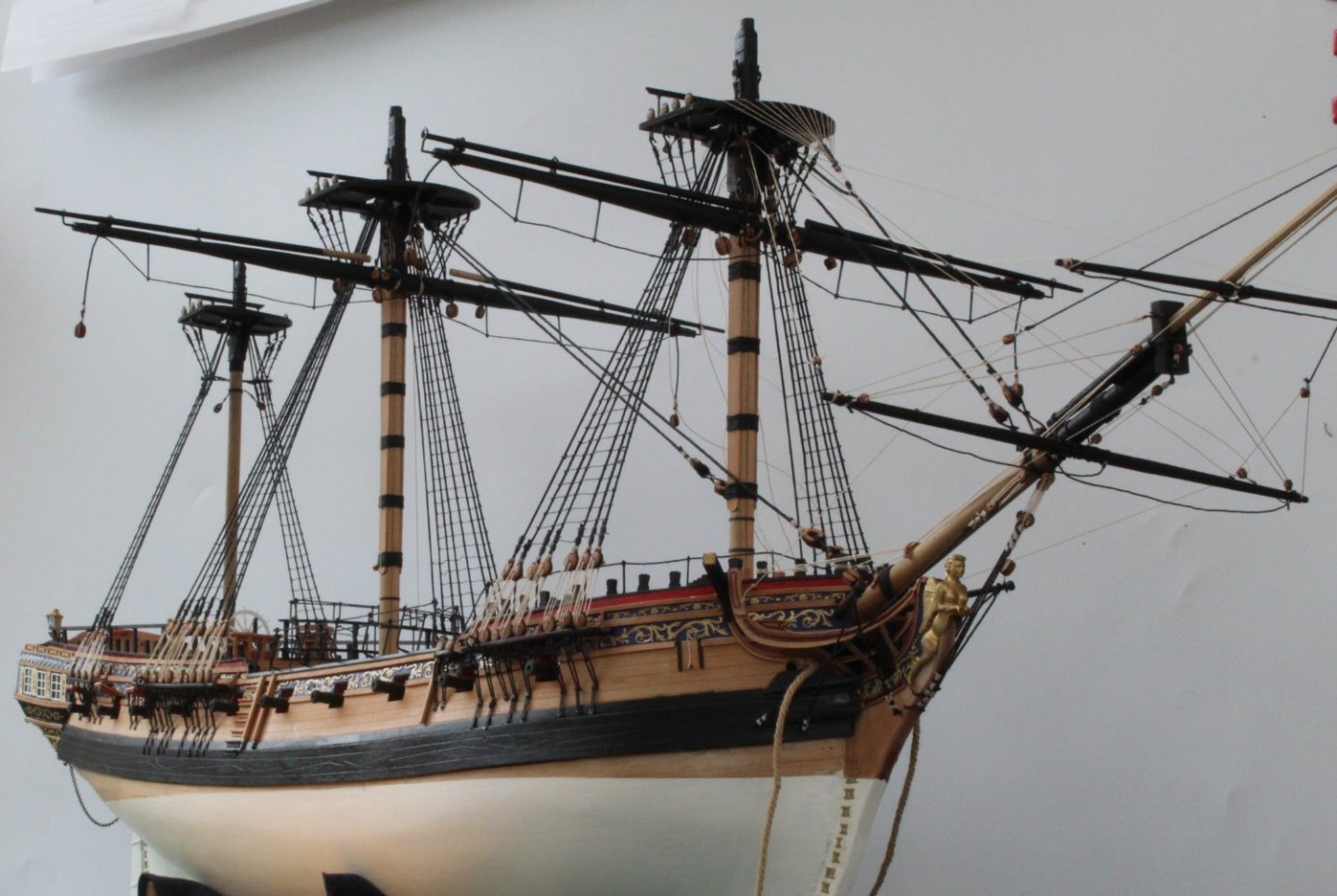
Foreyard - Completed I have now completed the work on the foreyard and it has been secured to the foremast. I might try to remove the braces as I not totally happy with their position because they need to be aft facing when rigged but they are hanging down on the bow side of the yard at the moment. It may be OK when the braces are rigged, time will tell. This is a close up of the jeers and truss pendants. The truss pendants have not been belayed as yet. When looking at rigging plan sheet 3 it appeared to me that the belaying point was on the chain pump assembly as can be seen below. Having checked Jim's build log (page 11) and confirmed by Chris (email) the correct belaying point is the bitts on the gallows. The next picture shows the stays which have been added to the foremast. The next photo shows a nice view of the fore and main masts complete with the yards. I have added the closed heart blocks to the main and preventor stays but I have not added the lanyards. I have used a couple of reverse action tweezers to show these stays in position.
- 476 replies
-
- 6
-
-
- sphinx
- vanguard models
- (and 1 more)
-
Many thanks. I have done it both ways but I am finding it easier doing this way, so far.
- 476 replies
-
- 1
-
-
- sphinx
- vanguard models
- (and 1 more)
-
Main Yard I have made quite a bit of progress with the main yard manufacture over the last couple of days. With the help of the proxxon mini lathe chisel set it was a much quicker process to shape the main yard. I was very happy with the end result. I even managed to make the central section octagonal The next task is to add the various blocks for the jeers, tacks & sheets and braces. I have assembled the various blocks which are now ready and waiting to be seized. I started with the jeers, noting there are two parts per side. These comprise 5mm double blocks and the completed jeer sets are shown below. I decided to add the 2 jeers blocks to the yard before moving on to the next set of blocks. The quad hands are a really useful tool to support the yard as the blocks are being added, as shown below. There are three block sets, per side for the sheets and tacks. I am using the bottom / top arrangement of half hitch knots for seizing the blocks. With the block held in the quad hands I start by adding a bottom half hitch knot, as shown below. With the bottom half hitch in place I repeat the process by adding a top half hitch knot. For most blocks I add a total of 6 bottom and 6 top half hitch knots and the seizing can be easily adjusted so it sits tight up to the block before the ends are secured with ca gel and trimmed. In the next picture the seizing is ready to be trimmed. The finished block is shown next. When there is a double block arrangement I will only add three top and bottom half hitches to the first block. The picture below shows the arrangement I use with the quad hands when adding the second block. And the next photo is the end result. The final task is to seize the two brace blocks which, according to the plans, requires a thimble (eyelet). After a little bit of thought I have refined the process I use to create the required thimble. I start by positioning the block in the quad hands as normal. I then take one free end of the thread back over the block which is held in place with my reverse action tweezers. The next picture shows this arrangement. After the seizing has been added the looped end is place over a suitable round object, in my case a metal pin, as shown below. The looped end can then be pull tight over the round pin before the seizing is secured with a touch of ca gel and the excess seizing thread is removed. The block has been gently lifted off the metal pin in the picture below. The remaining free ends of thread can be trimmed as required to end up with a nice looking block complete with a thimble eyelet. To complete the brace block a length of 0.75mm black thread is fed through the thimble and is then placed in the quad hands ready to be seized. This is shown in the next photo. One of the two completed block for the braces is shown below. With all the blocks seized they are now ready to be added to the main yard.


- 476 replies
-
- 9
-
-
- sphinx
- vanguard models
- (and 1 more)
-
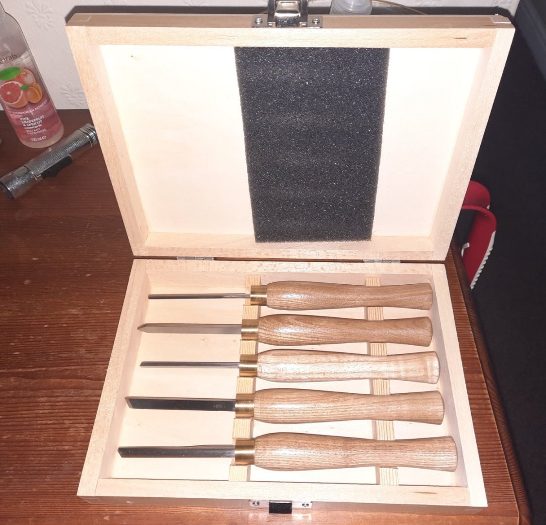
Due to the really nice weather for the last two days I have been outside doing some gardening and sunbathing. Today I received a new set of tools which will complement my Proxxon mini lathe. I plan to try them out tomorrow, unless its another hot 🌞 day. I think these will help me tremendously with manufacturing masts and yards.
- 476 replies
-
- 5
-
-
- sphinx
- vanguard models
- (and 1 more)
-
Looks like you're doing a great job on your build.
- 118 replies
-
- 3
-
-
- Duchess Of Kingston
- Finished
- (and 1 more)
-
I have has a look at my completed build and the my mizzen mast rake angle looks good and as far as I can tell it matches what is shown in the manual and plan sheets.
-
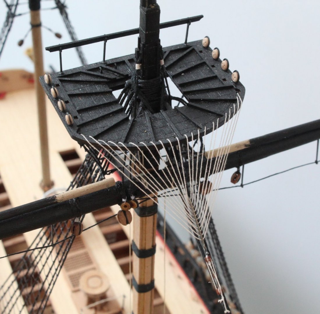
Crows Feet - Foremast I experimented this morning with trying to secure the free end of thread using a knot which could be positioned uptight to the underside base of the platform. I was using a basic half hitch but after several attempts I decided it was an impossible task and I was ready to ask for help. It then occurred to me there must be another way to do it such as using a slip knot. After a quick lesson (via the internet) on how to tie a slip knot I tried one on my test arrangement which was simply a spare platform part held in my quad hands. Once I had mastered how to tie the knot it became apparent I would be able to adjust its position to the underside of the platform base. Turning my attention to the free end of thread from the foremast crows feet rigging I tied a slip knot. Next I adjusted the tension in the crows feet rigging lines and once I was happy with how it was looking I was able to move the slip note into the required position. I then applied a touch of ca gel to the knot and cut away the excess thread. Using the same test set up I added a belying pin to the platform and I was able to replicate securing a free end of thread to a belaying pin. Of course it is much easier to do when there is nothing in the way to hinder access. That said I have found a method which seems to work and looks good.

- 476 replies
-
- 10
-
-
- sphinx
- vanguard models
- (and 1 more)