Glenn-UK
-
Posts
3,175 -
Joined
-
Last visited
Content Type
Profiles
Forums
Gallery
Events
Everything posted by Glenn-UK
-
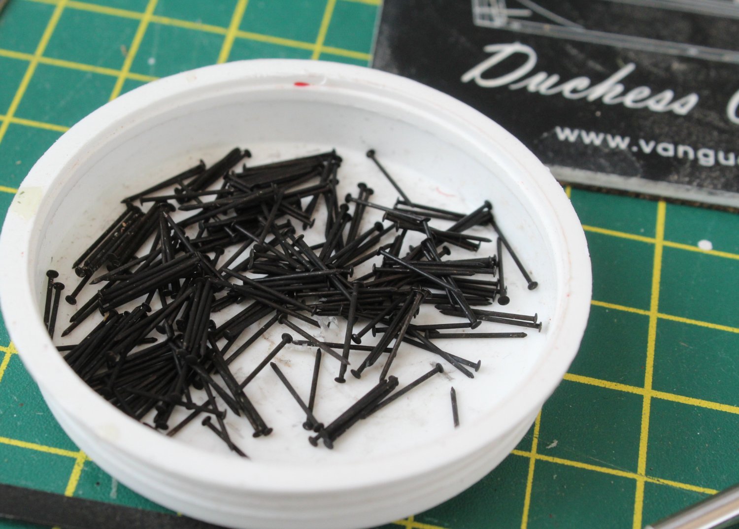
 Deadeyes and chain plate The three mast platforms have now been fitted with various 3mm deadeyes /strop assemblies. Starting with the mizzen mast the 6 x 3mm deadeyes were added to the strops and placed in position. Each strop was opened open slightly using my round nose pliers so the deadeye can be added. I took great care to ensure the deadeye was correctly aligned in the strop before the closing the strop back up. The process was then repeated for the main and foremasts. I did run a micro drill through the deadeyes to ensure the holes were clear before they were added to the strops. The following picture shows the main mast deadeyes ready to be added to the strops It was then a case of opening up the strops slightly and then adding the deadeyes. As with the mizzen mast great care was taken to ensure the deadeyes were correctly aligned. The following picture shows the completed main mast assemblies prior to fitting to main mast platform. The completed strop/deadeye assemblies were then added to the platform, the picture below is of the mainmast platform. I then took some brass pins and after cleaning them in acetone and hot soapy water they were blackened. Moving on to the channels the first task was to add the stunsail boom bracket and boom iron to both the fore and main mast channels. The boom irons located in the fixing holes on the channels without any problems. I then added two shortened blackened pins to each end of the stunsail boom brackets and then added them to the channels. Once in place a third shortened blackened pins was added the stunsail boom bracket central hole. I also checked the various strops and eyebolts would be fit OK in the channels, as can be seen below. It was relatively easy to add the 3mm deadeyes to their respective strops, as the strops only required to be opened slightly. I am finding it much more difficult to add the 5mm deadeyes to their respective strops. Once the 5mm deadeye has been added to the the strop adding the preventer and chain plate upper and lower links is straightforward. These links were secured in place using the blackened pins. It is important to place the upper chain plate link the right-way round and to apply a slight bend to the end where the pin is to be fitted. The access slot in the preventer link is positioned to face the hull.
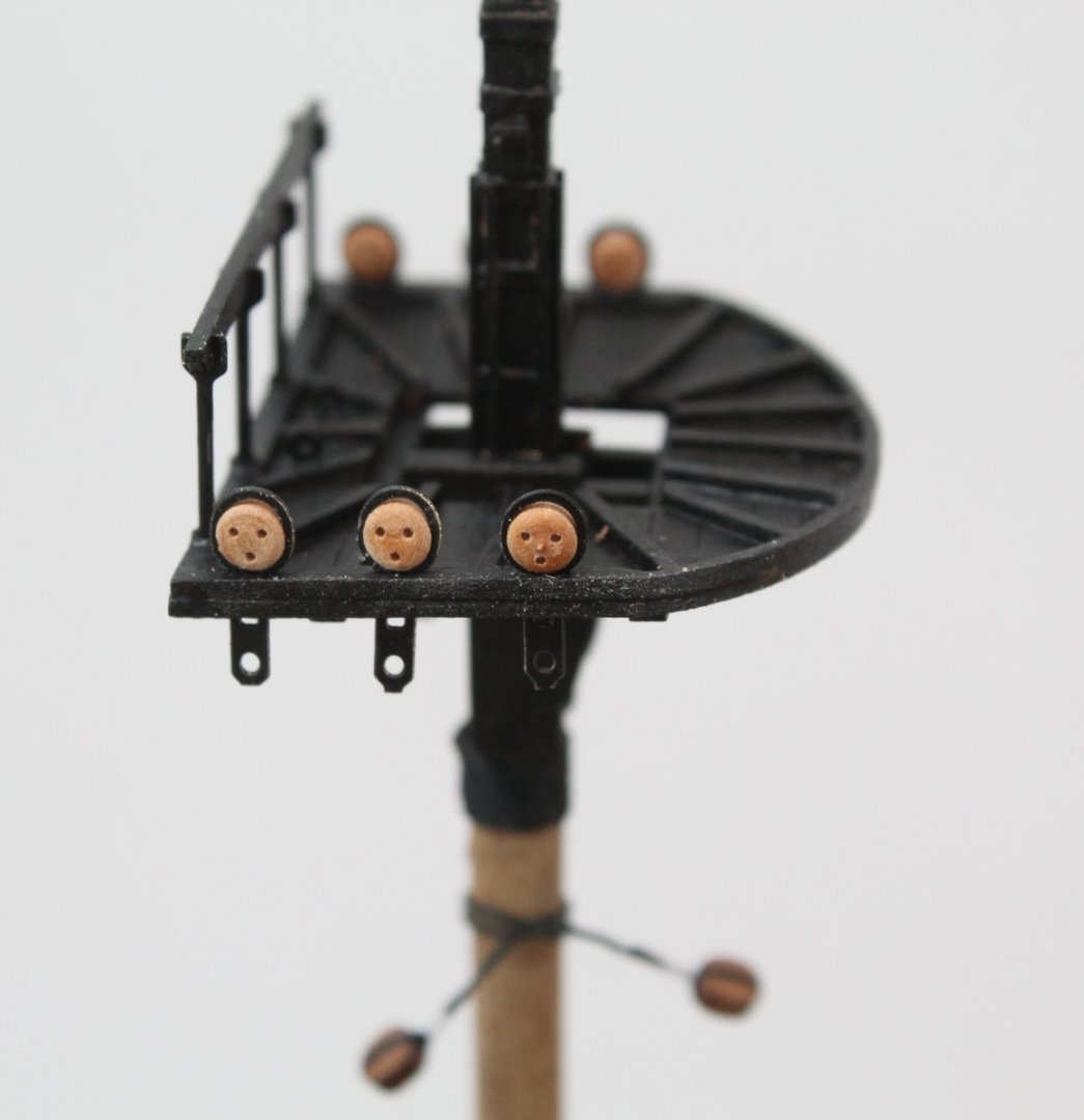


- 476 replies
-
- 7
-

-
- sphinx
- vanguard models
- (and 1 more)
-
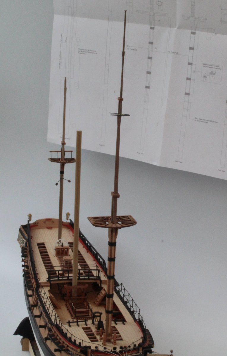
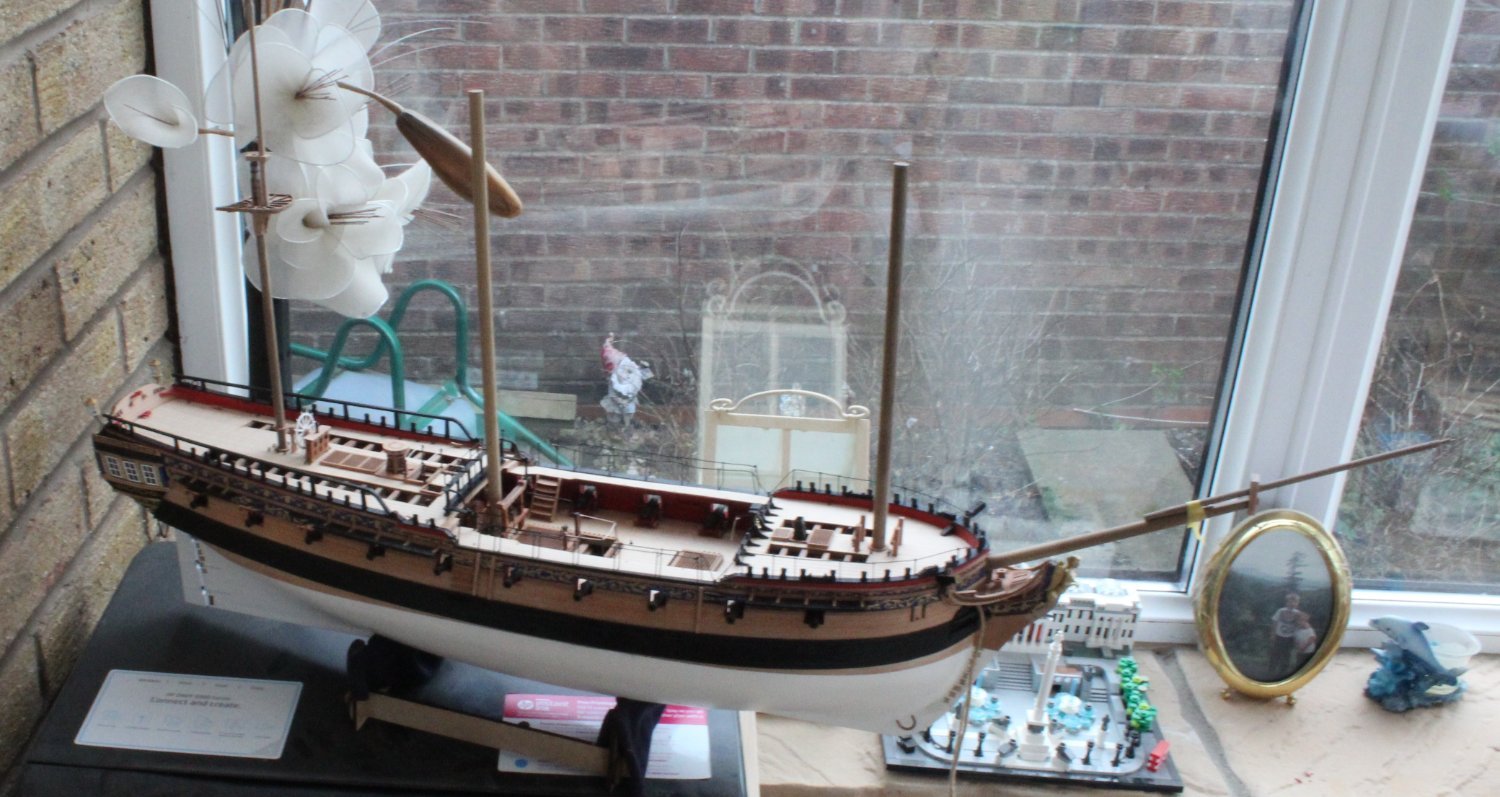
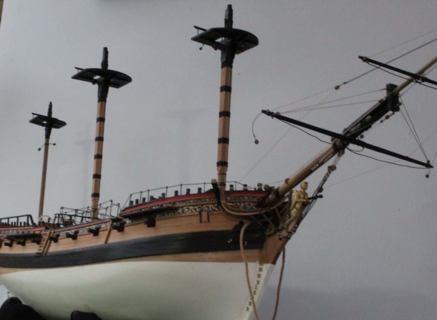
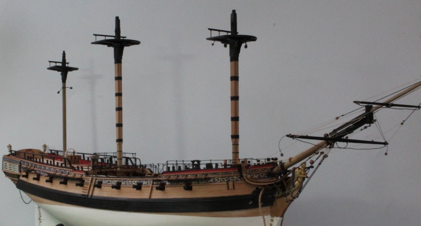
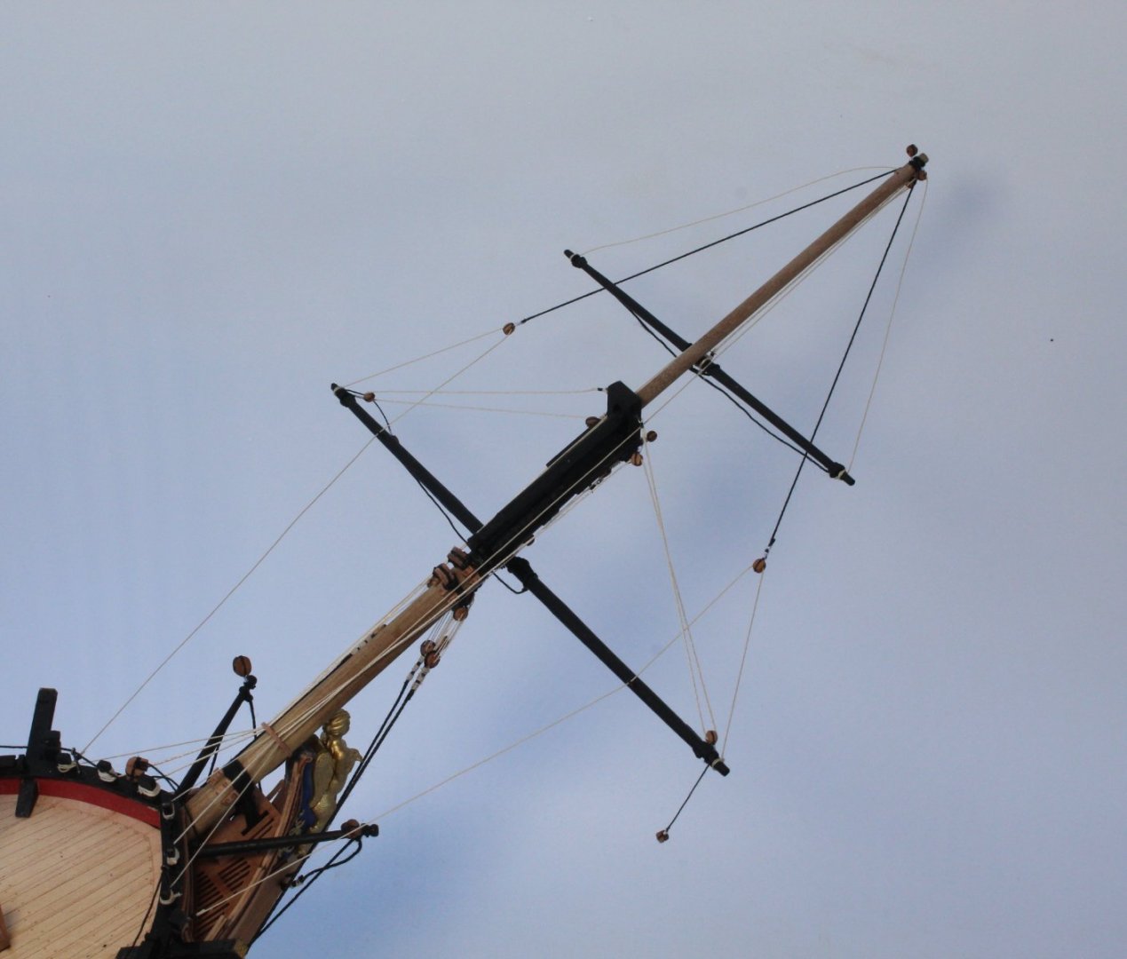
Masts I have now completed fabricating all the masts. The two pictures below show the Fore, Main and mizzen masts in position without glue. The top and topgallant masts for the fore, main and mizzen are also complete. I still have to fabricate the various yards. My next task will be to fit the deadeyes and chain plates to the channels. Once that is complete I can work on adding the burton pendants and then then the lower shroud lines. I might run in the spritsail yard brace lines before the shrouds for easy of access.
- 476 replies
-
- 7
-
-
- sphinx
- vanguard models
- (and 1 more)
-
Foremast Preparation for adding blocks When looking at plan sheets I worked out the following blocks needed to be added to the foremast: 1 x 5mm single block 1 x 4mm single block 2 x 5mm double blocks with loops 4 x 4mm double blocks with eyebolts 2 x 3mm single blocks with eyebolts The purpose of the post is to detail the process I use prior to seizing the blocks to the threads as I have not been able to spend much time in the ship yard this week. 2 x 5mm double blocks I started by making the loop ends. Once the loops had been formed I coated them with diluted pva to ensure they retain their shape. I also referred to the rigging plans to determine which rigging thread will pass through the block holes. The following photo was taken after the loops had been created and coated with pva. I also checked the 0.25mm natural thread would pass through the block holes (both sides). 5mm and 4mm single blocks In the next photo the 5mm and 4mm single blocks have been seized to the thread. I have also checked that the 0.75mm (4mm block) and 1mm black thread (5mm block) will pass through these blocks. 2 x 3mm single blocks I have checked the thread (0.25mm natural) will pass through the 3mm single blocks. The blocks are now ready to be seized along with the eyebolts. 4 x 4mm double blocks Finally I checked the 0.25mm natural thread will pass through the 4 x 4mm double blocks (both sides) which are now ready to be seized along with the eyebolts.
- 476 replies
-
- 7
-
-
- sphinx
- vanguard models
- (and 1 more)
-
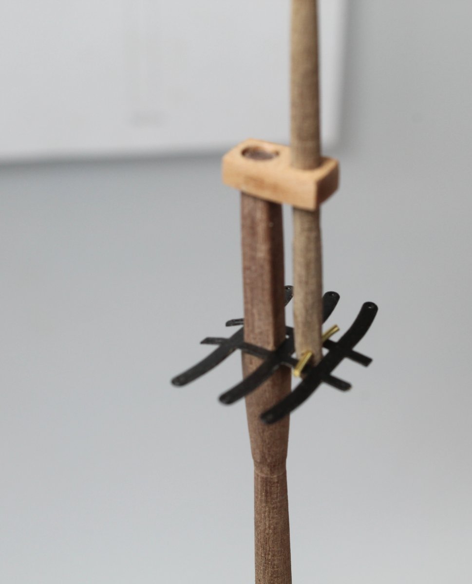
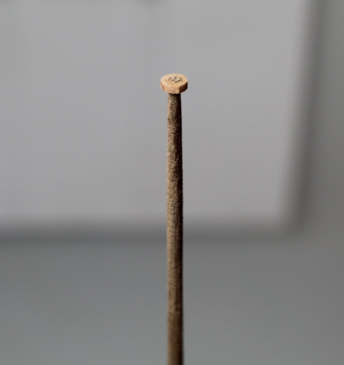
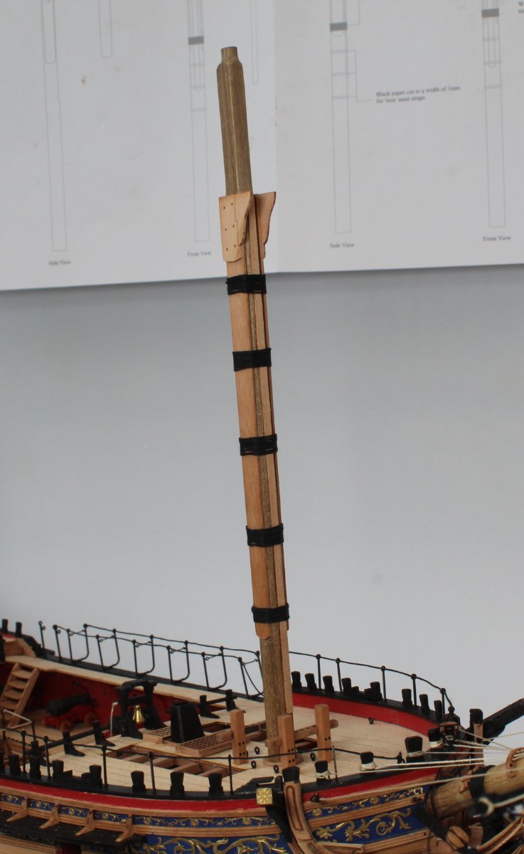
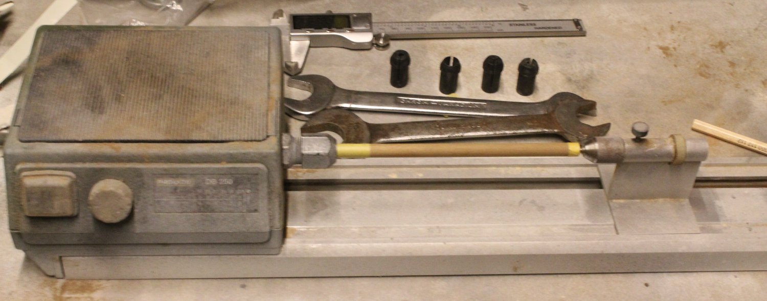
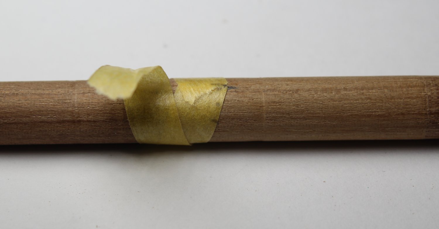
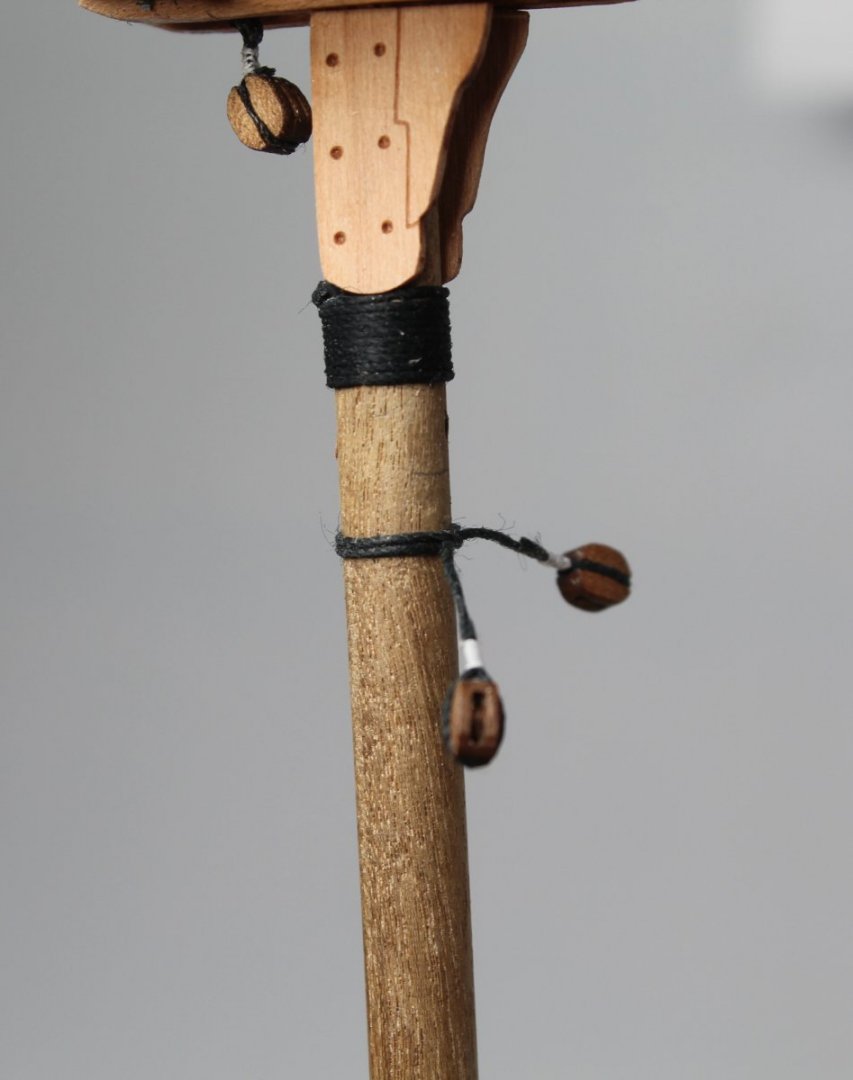
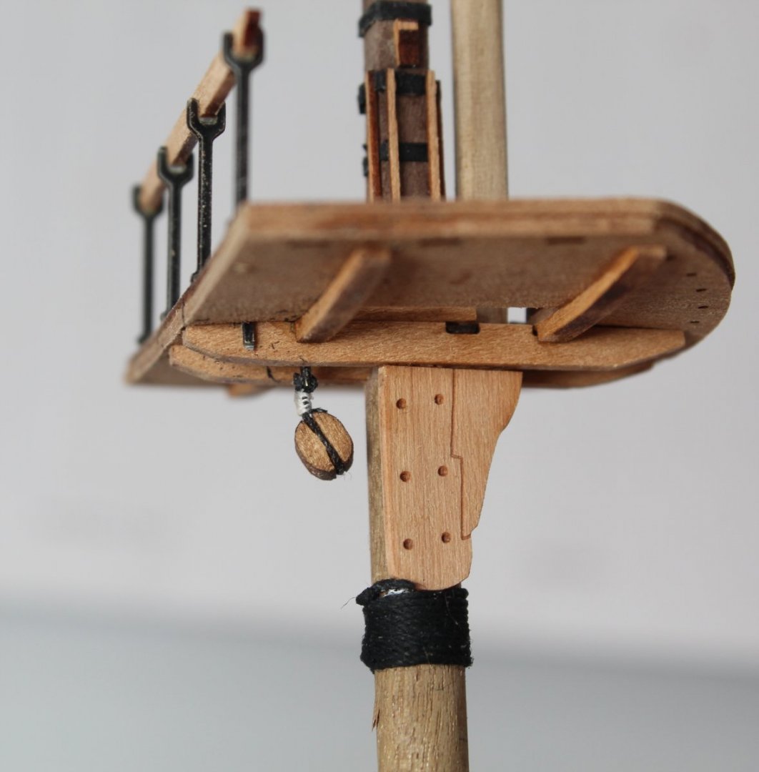
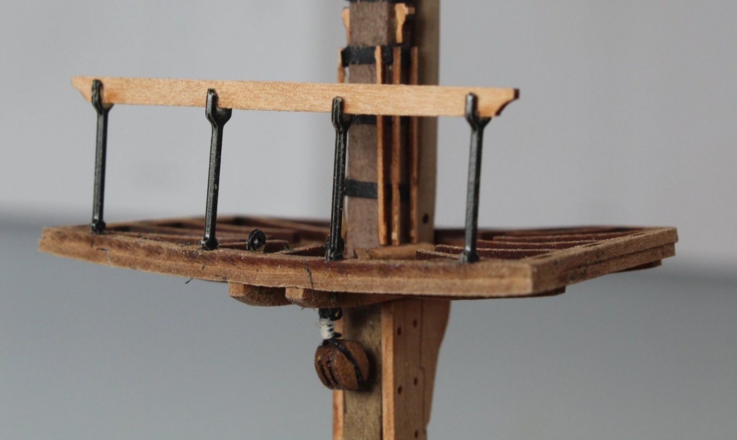
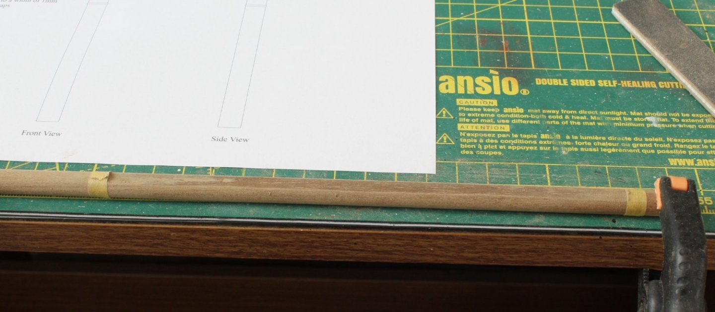
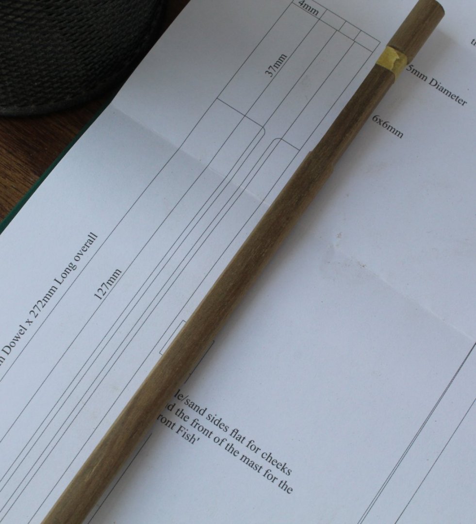
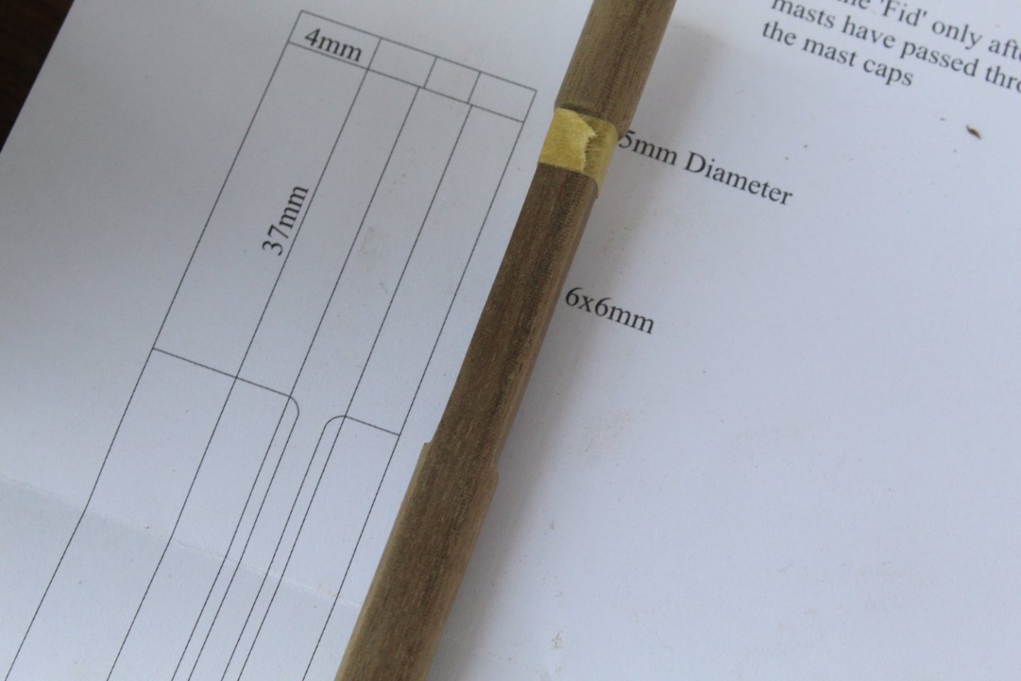
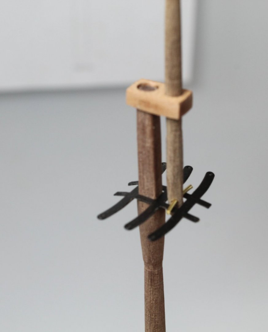
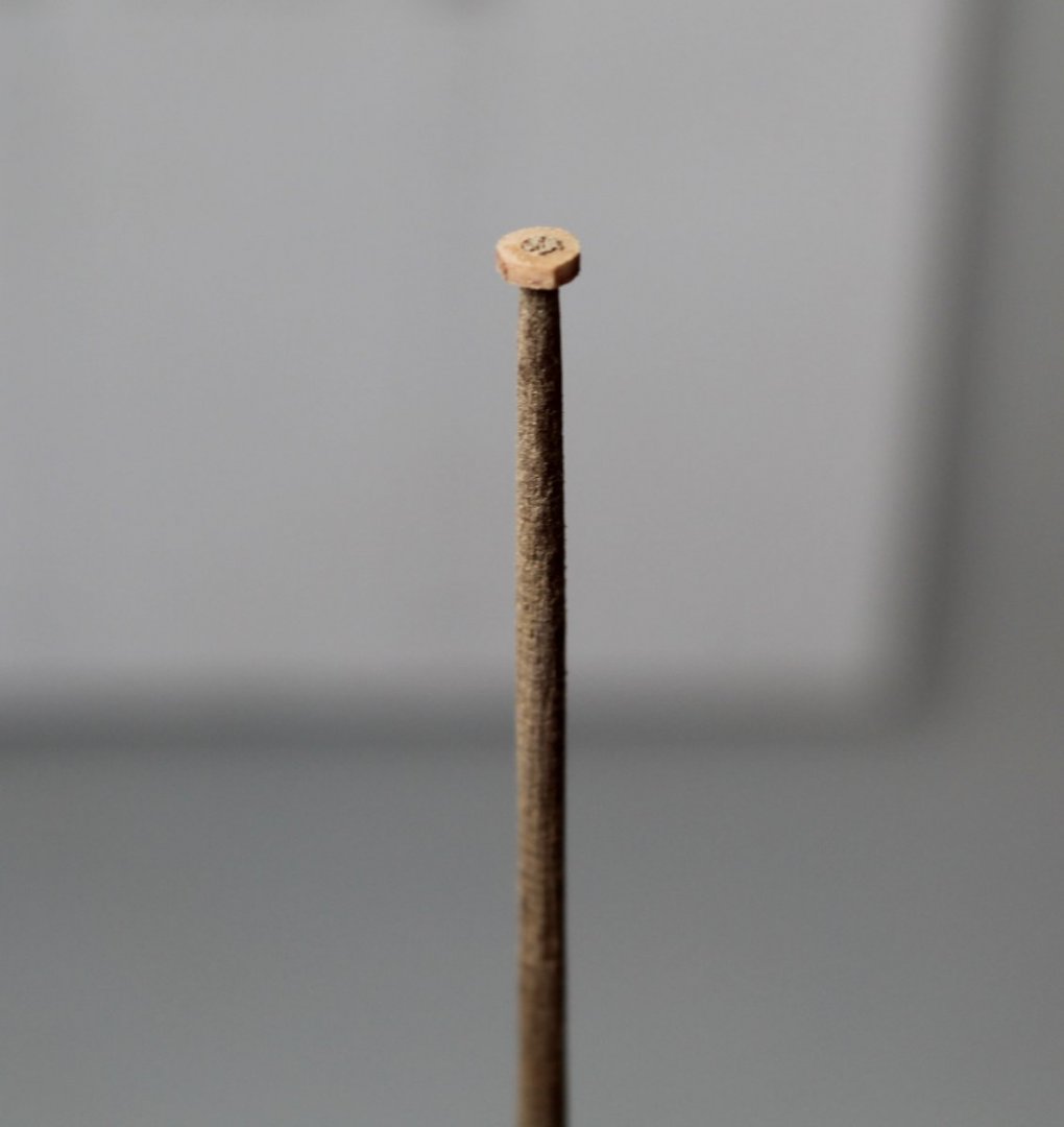
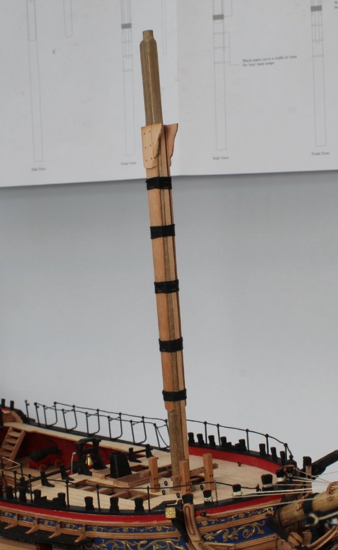
Mizzen Mast I have now completed the fabrication work on the mizzen mast. The section between the mizzen mast end cap and the bottom of the bibs still needs to be painted black before the rigging phase. There two blocks located on the mizzen mast, just below the crossjack yard will be positioned. Before adding these blocks I did a test fit of the thread, using a clove hitch knot. This enabled me to work out the required distance between the two blocks, which was approx. 68mm. It also confirmed I would able able to use a clove hitch knot with a short length of thread. Once the two blocks were seized to either end of the thread I was able to secure to the mizzen mast using a clove hitch knot. The photo below shows the two blocks in position along with the wolding. Although it can not be seen I have also drilled a hole for the crossjack yard locating pin. A block was seized to an eyebolt and then secured to the underside of the platform. I did check to make sure the eyebolt and block were correctly aligned as per the plan sheets. Another block was added to an eyebolt and then added to the end cap. Again the eyebolt and block alignment was in line with the plan sheet. As reported in a previous post I had an issue with the warping on the platform which I have corrected (almost). I decided it was best to add the rear platform rail assembly which may help prevent any further warping. Foremast assembly work I then moved on to start work on the foremast fabrication. I started with adding the two flat edges for the cheeks. With the section to flattened taped the dowel was clamped to my workbench. I then used my craft knife to create the first flat edge in unison with a Florey sanding stick. The cheek is 1mm thick so I know I need to remove 1mm from the 8mm dowel, i.e. 7mm wide with the after the first flat edge has been created and then 6mm wide when both flat edges are done. Using my digital vernier I checked the width along the length of the dowel, as the material was removed. As can be seen in the photo below I have almost completed the first flat edge. I did also use one of the cheeks to check it's fit, remembering to add the curved section at the lower end to match the shape of the cheek. With the two flats created for the cheeks the next area I worked on was to create the 6mm square section, which the platform will slide over. The foremast is checked against the plan sheet to make sure everything as it should be. The 6mm square section looks good. The 6mm section is the correct length, although it does not look like that in the photo below. The final fabrication task is to reduce the top section down from 8mm to 5mm ready for the end cap. The Proxxen mini lathe made short work of this task. Rapidly moving on the foretop mast was fabricated and test fitted with the foremast. The end cap is not full seated in the photo below, but is a very good tight fit. I used a length of copper bar for the FID for the test fit. The next photo shows the foretop and fore topgallant masts in place, test fitted only. Once again I am using a copper bar for the FID for this dry fit test. The topgallant mast end cap is a good fit to the tapered end of the fore topgallant mast. It was a bit fiddly to remove the laser char from the visible edge of the edge cap. . The 5 x woldings, 2 x bibs and the front fish were then added to the foremast. I did create a flat edge for the front fish before it was glued in place. There is still a bit more work to be done before the foremast work is complete, such as adding the iron bands and various blocks. The next photo shows the foremast assembly with the mizzen mast assembly in the background. These assemblies are only dry fitted at this stage. My current thinking is once I have completed all the fabrication work on both the fore and main mast I will add the burton pendants and shrouds to the mizzen, main and foremasts before fitting their respective top masts are added. However planning ahead I have already pre-cut all the dowels for the various yards.


- 476 replies
-
- 7
-
-
- sphinx
- vanguard models
- (and 1 more)
-
Thanks Rusty. I shall do my best to log my progress and methods. Most of my methods are copied from other builders.
- 476 replies
-
- 2
-
-
- sphinx
- vanguard models
- (and 1 more)
-
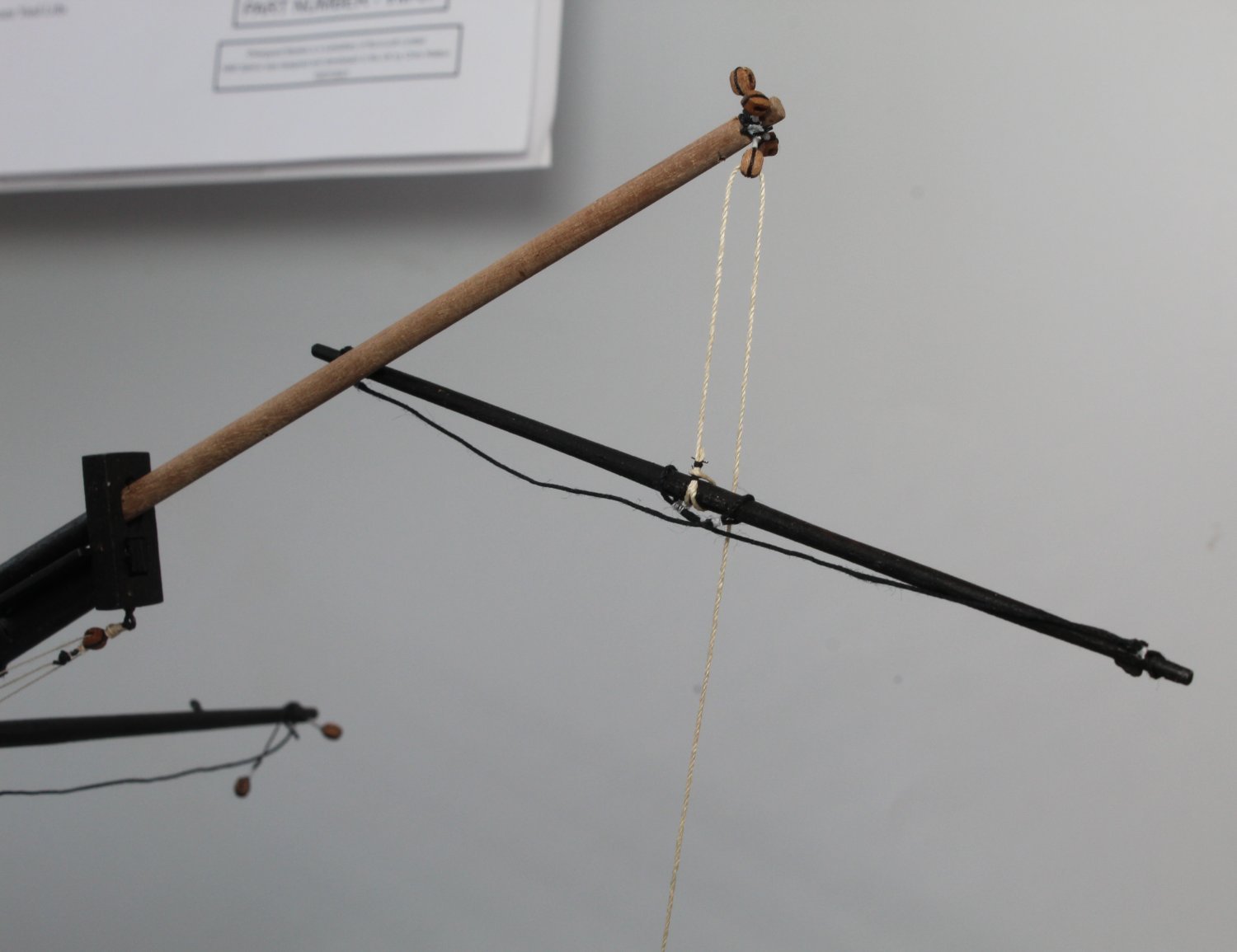
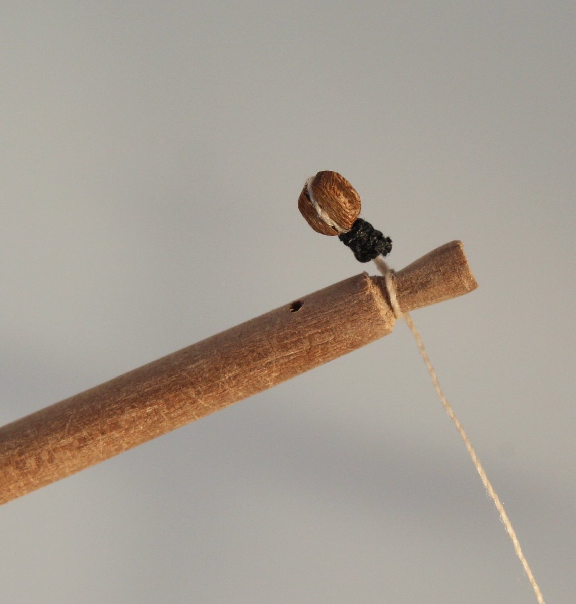
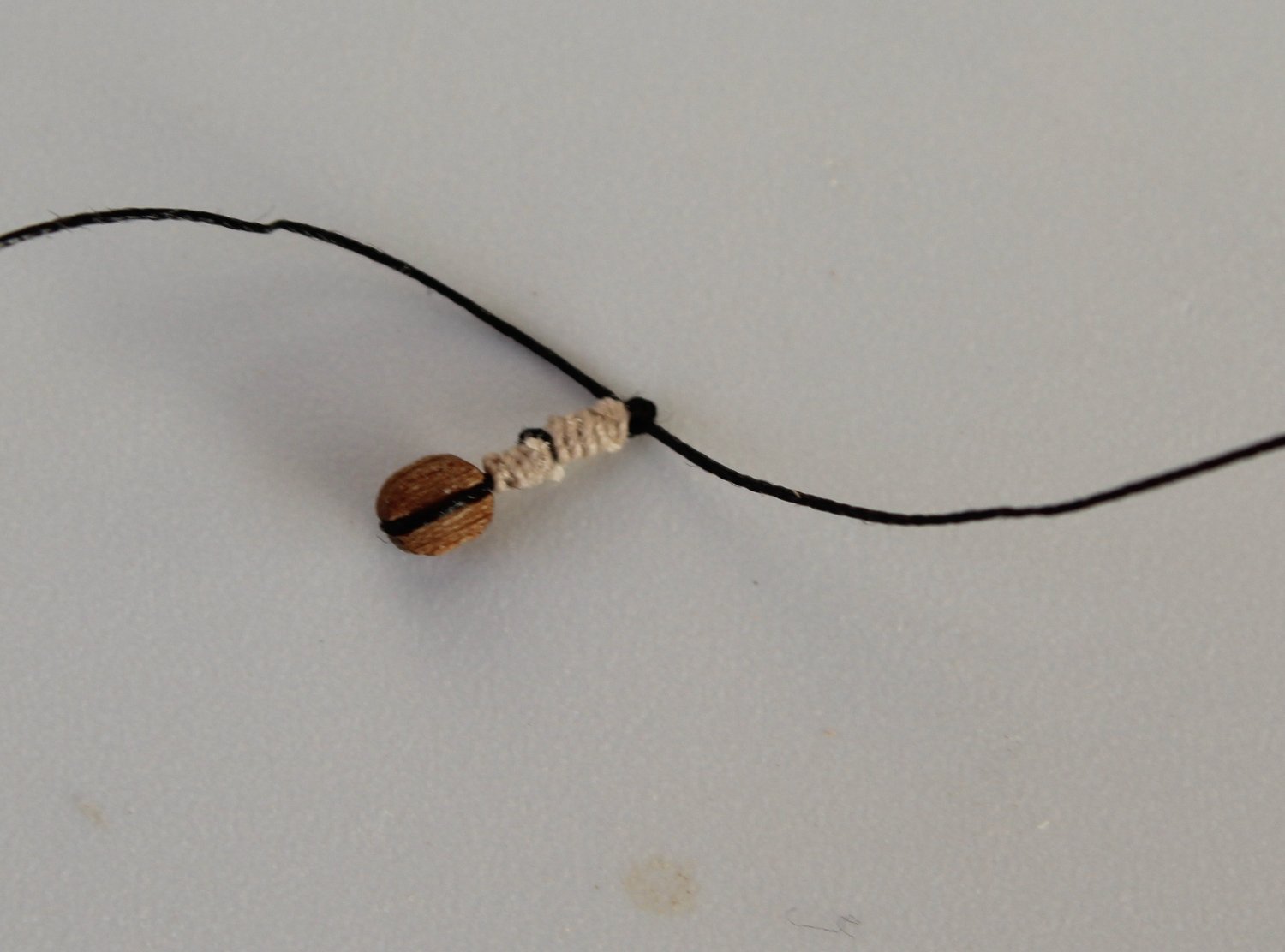
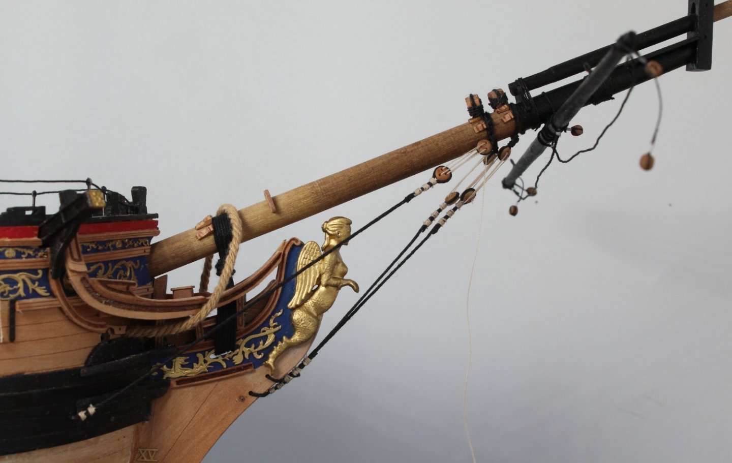
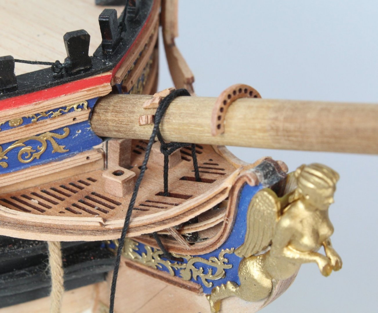
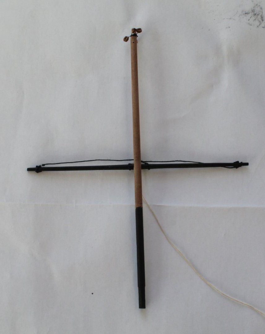
I am very pleased to report I have been able to fix the slack line reported in my previous post. This is the photo showing the problem before the fix was made. The next photo shows the rigging after the fix. I was able to add another loop of the thread around the spritsail topsail end which tensioned the line back to what it should be. I am sorry about all the shadows displayed on the white screen from the evening sun. I can now move on to fabrication of the main and fore masts.

- 476 replies
-
- 11
-
-
- sphinx
- vanguard models
- (and 1 more)
-
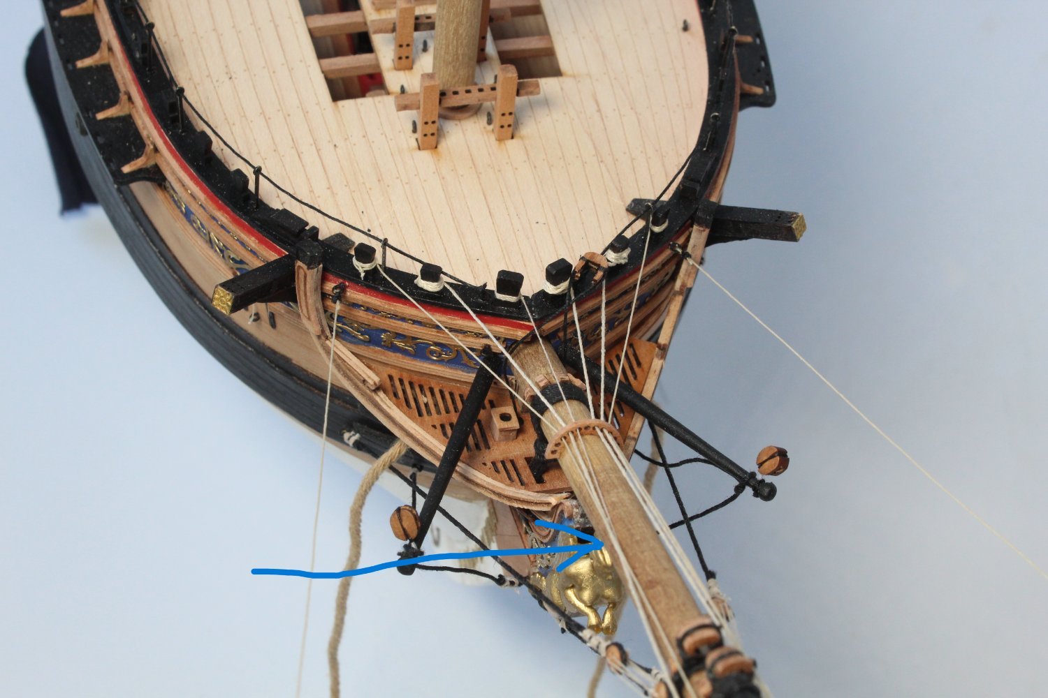
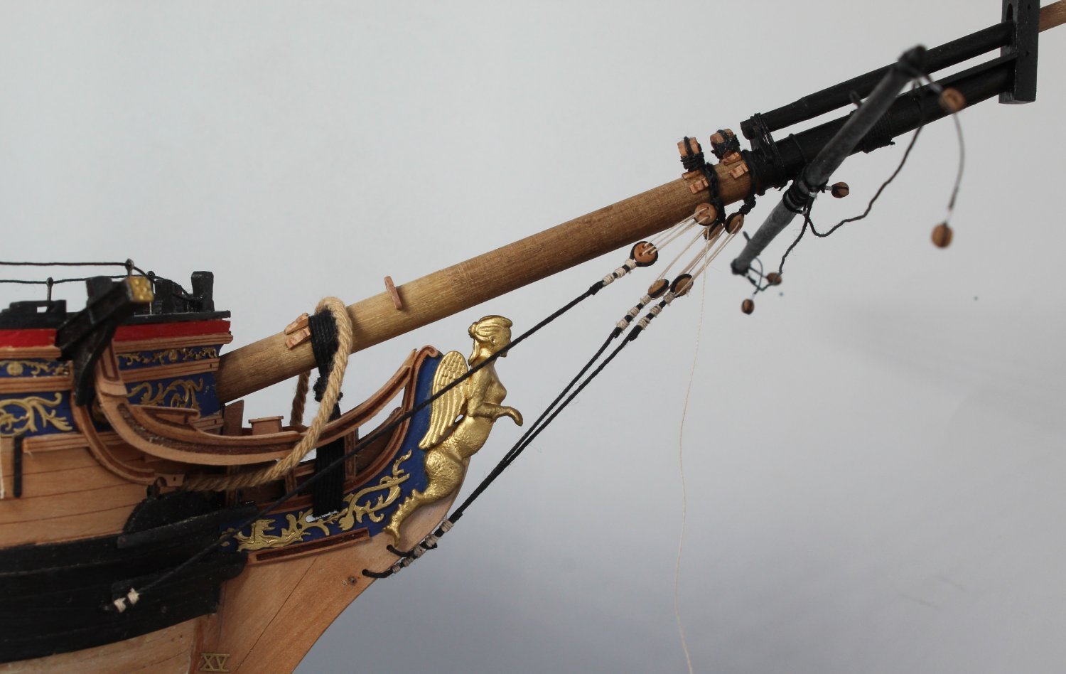
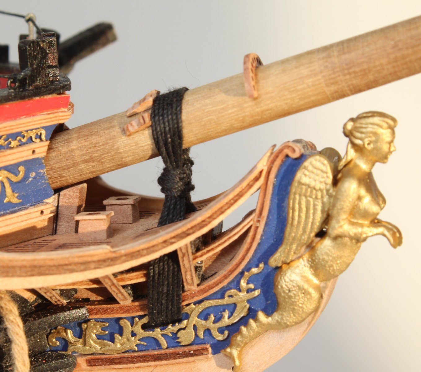
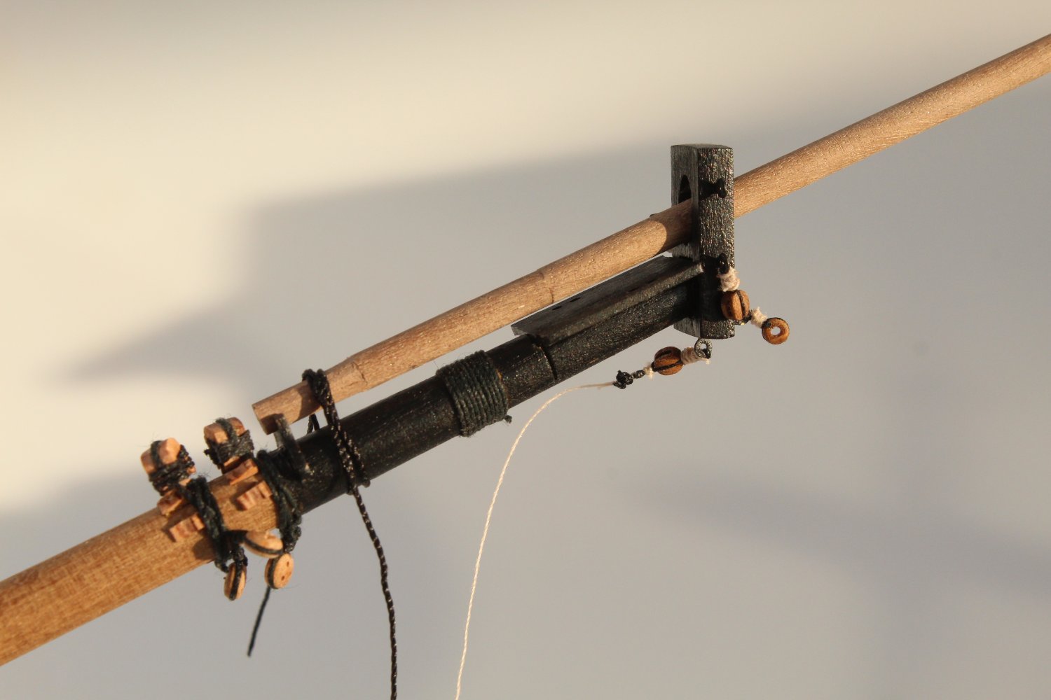
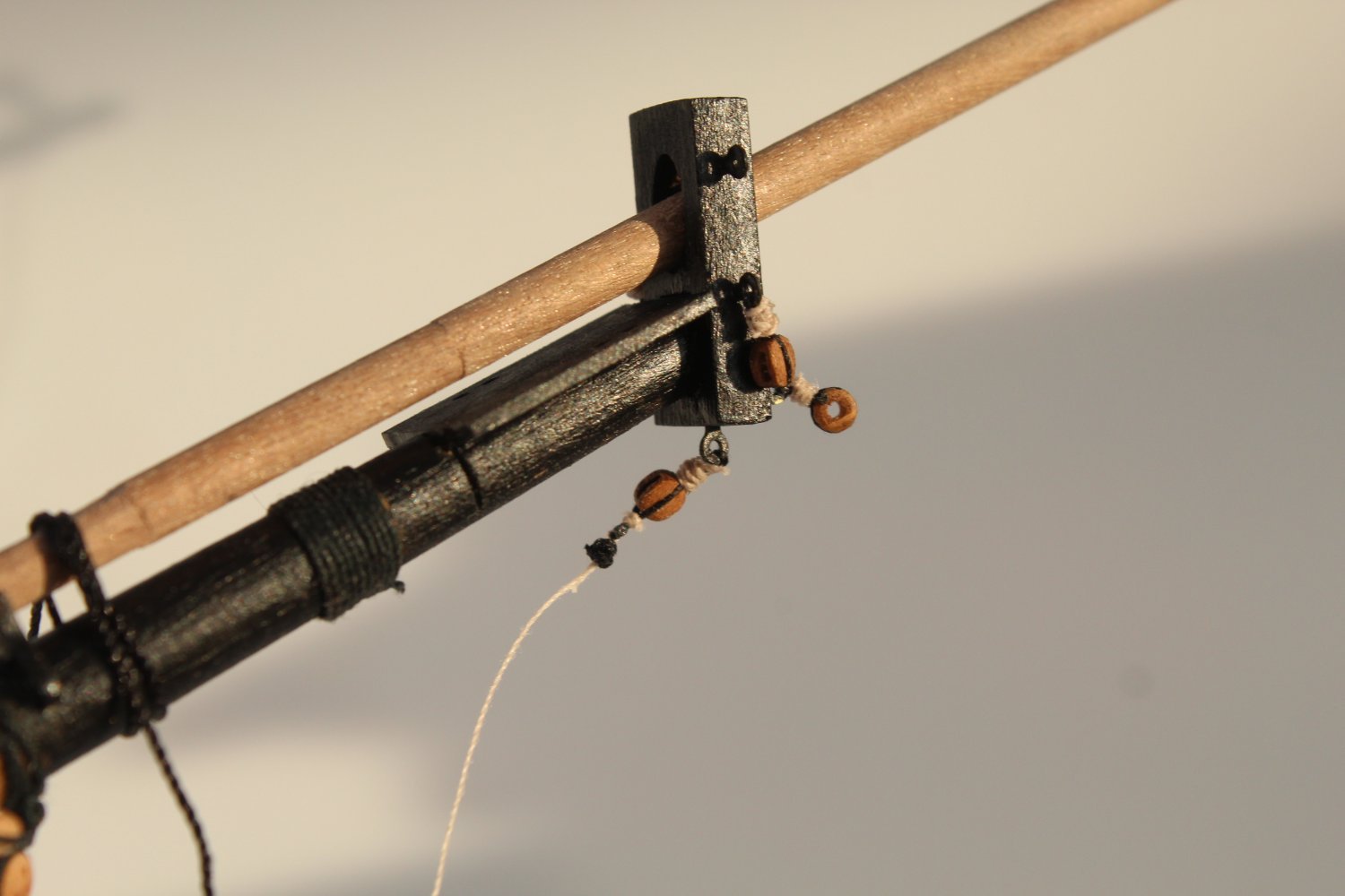
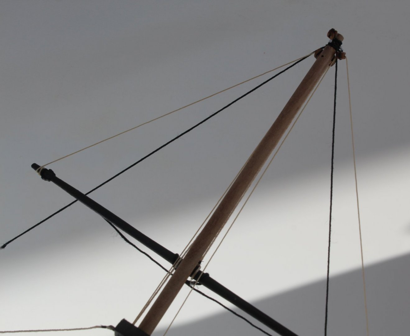
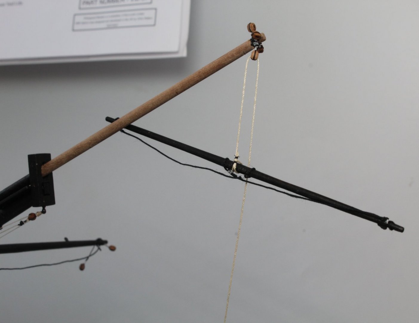
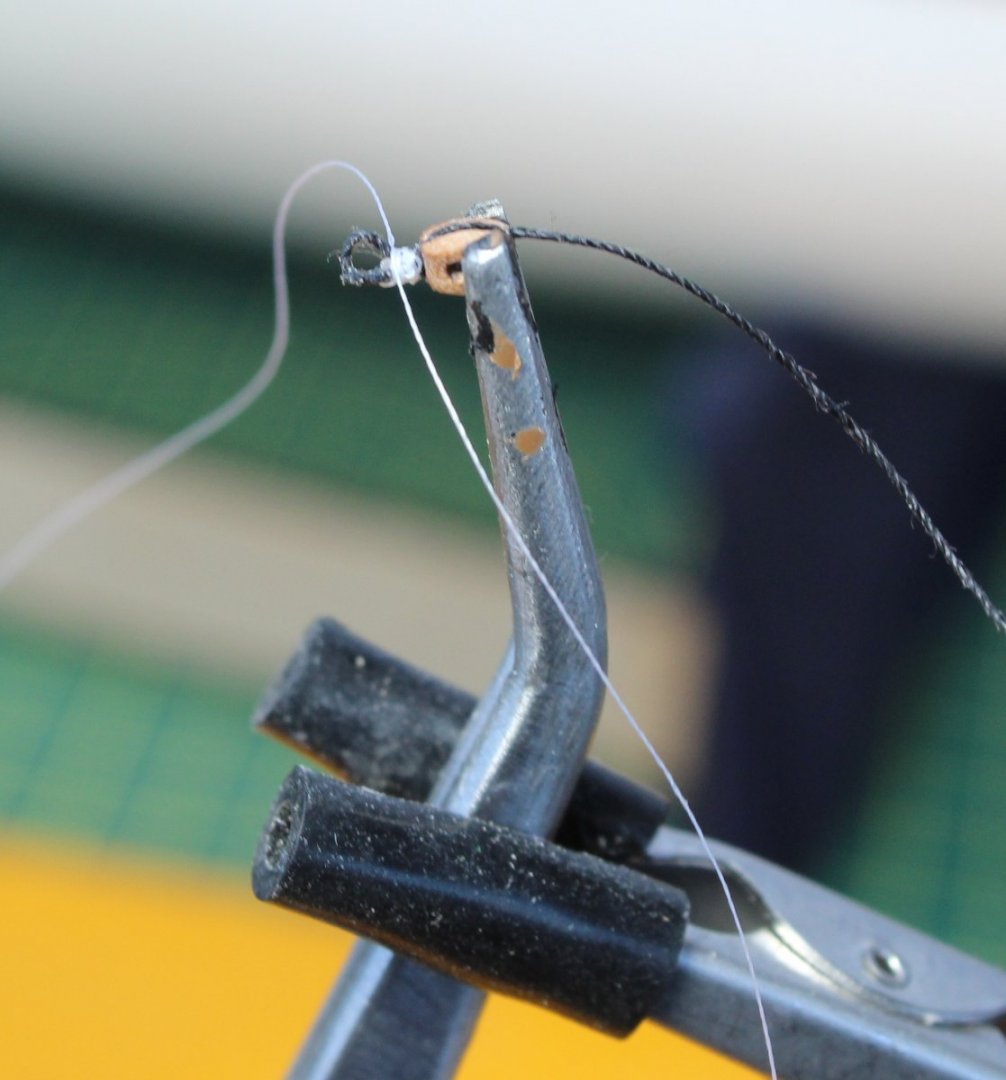
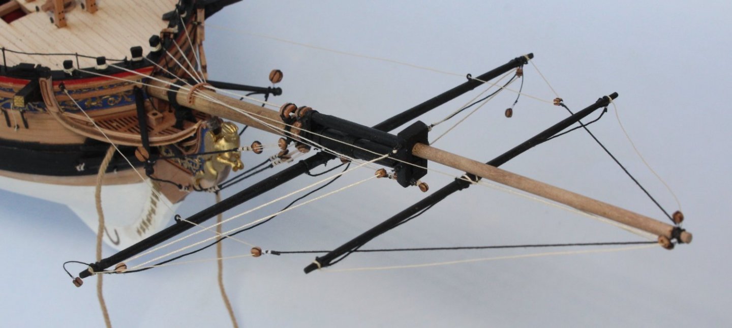
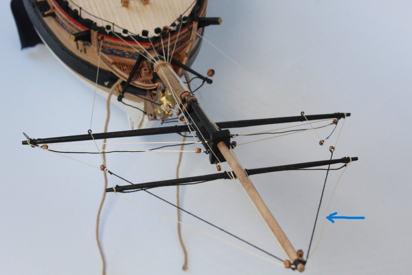
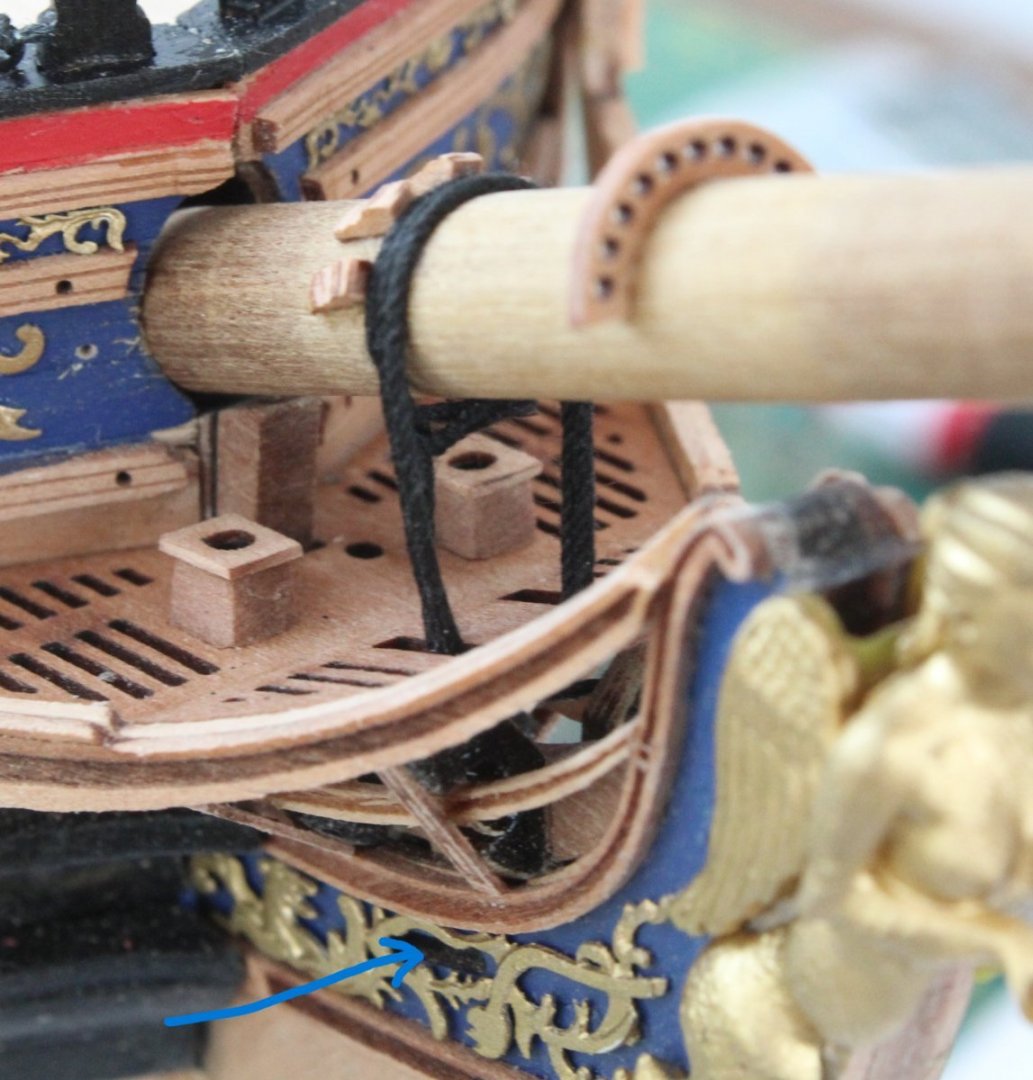
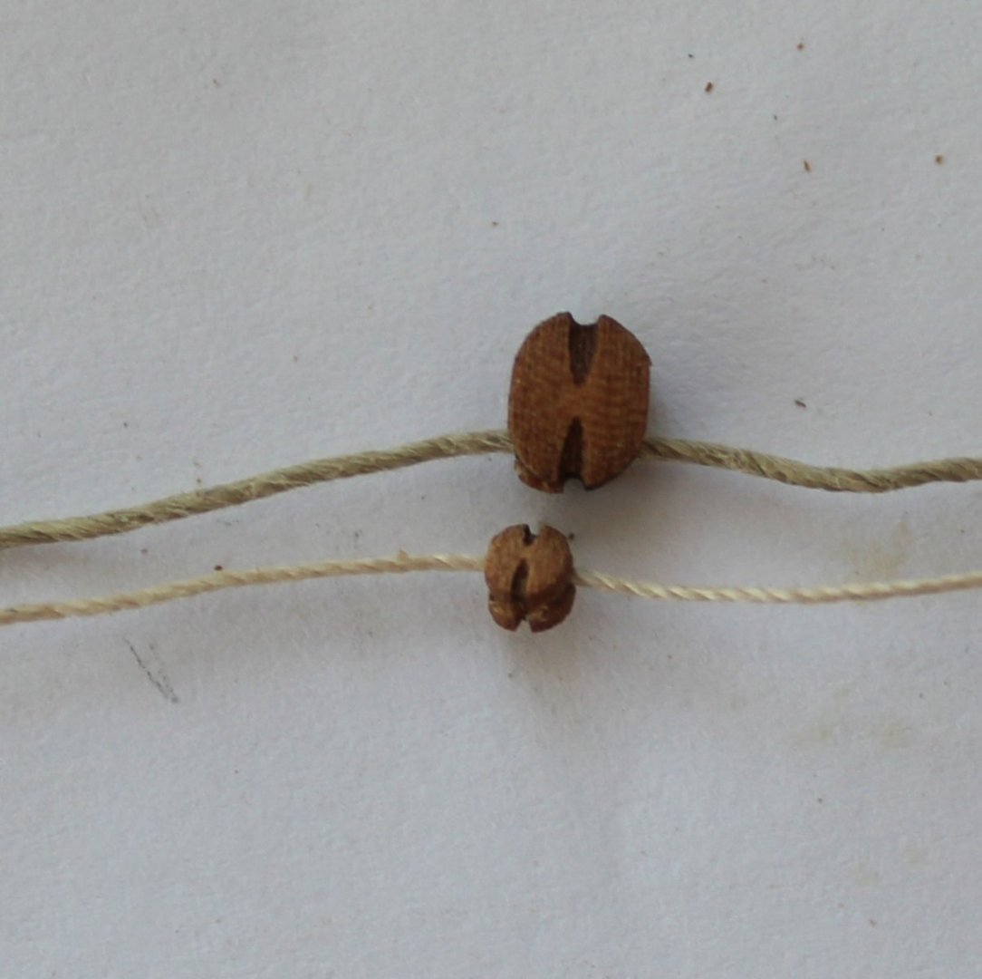
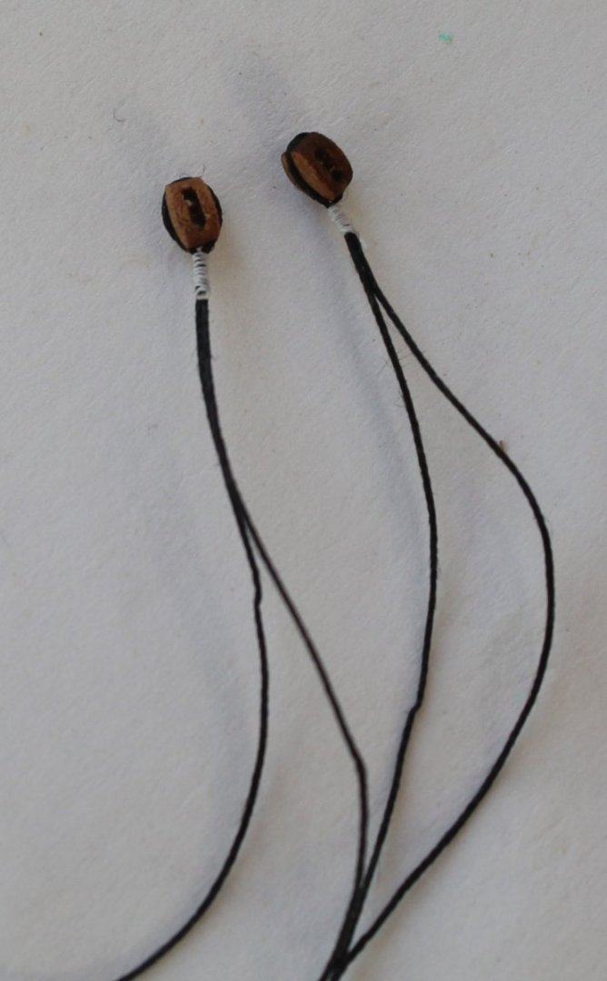
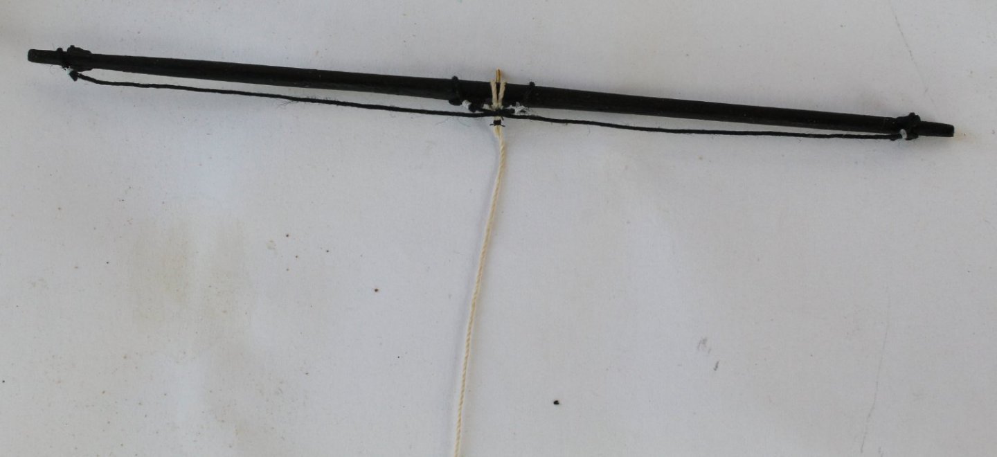
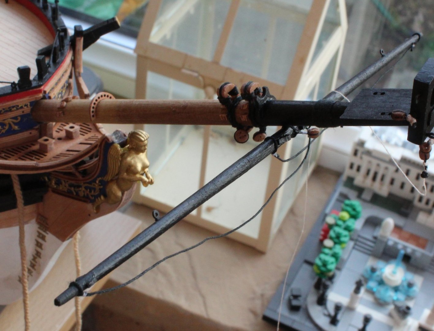
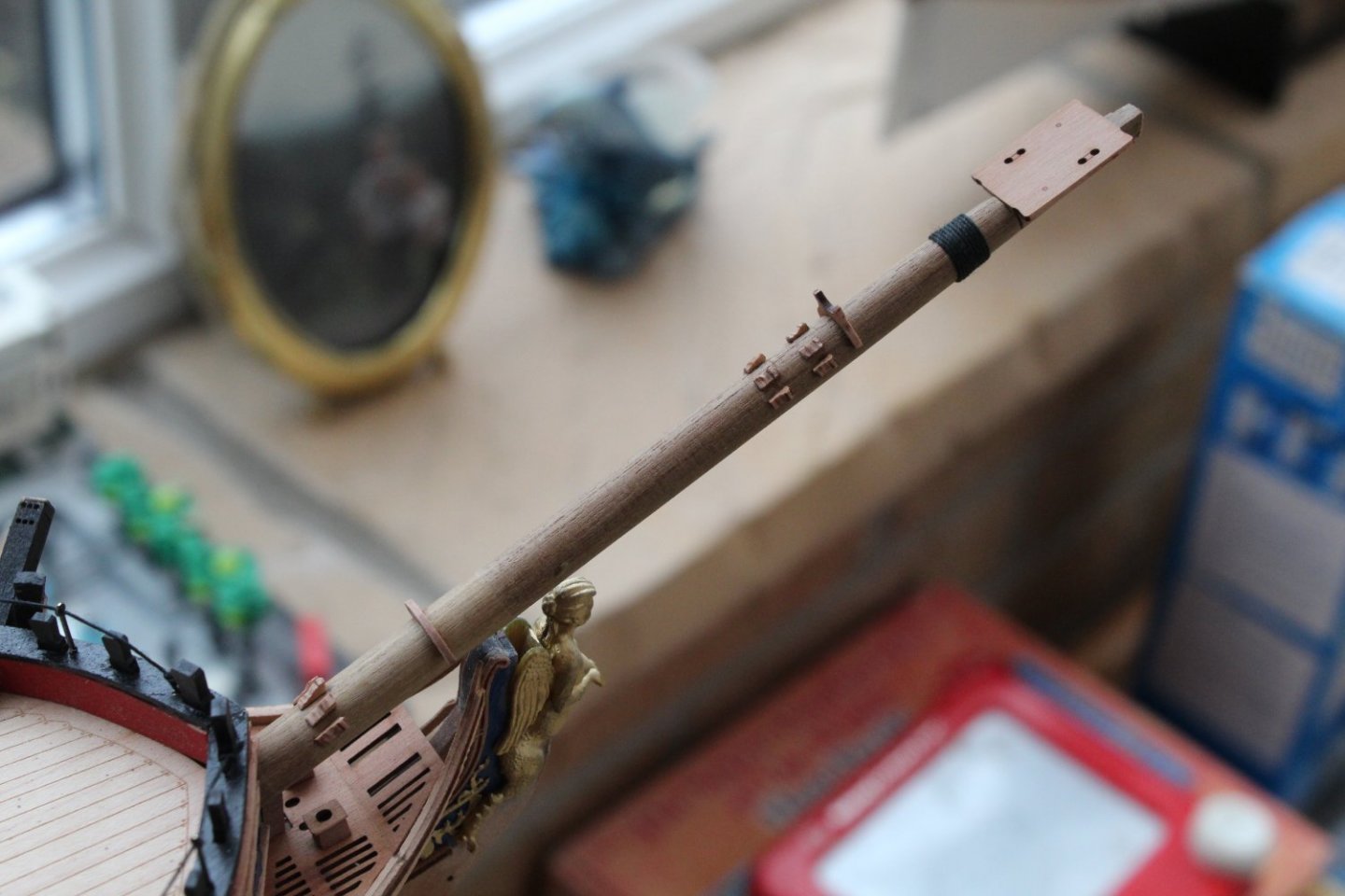
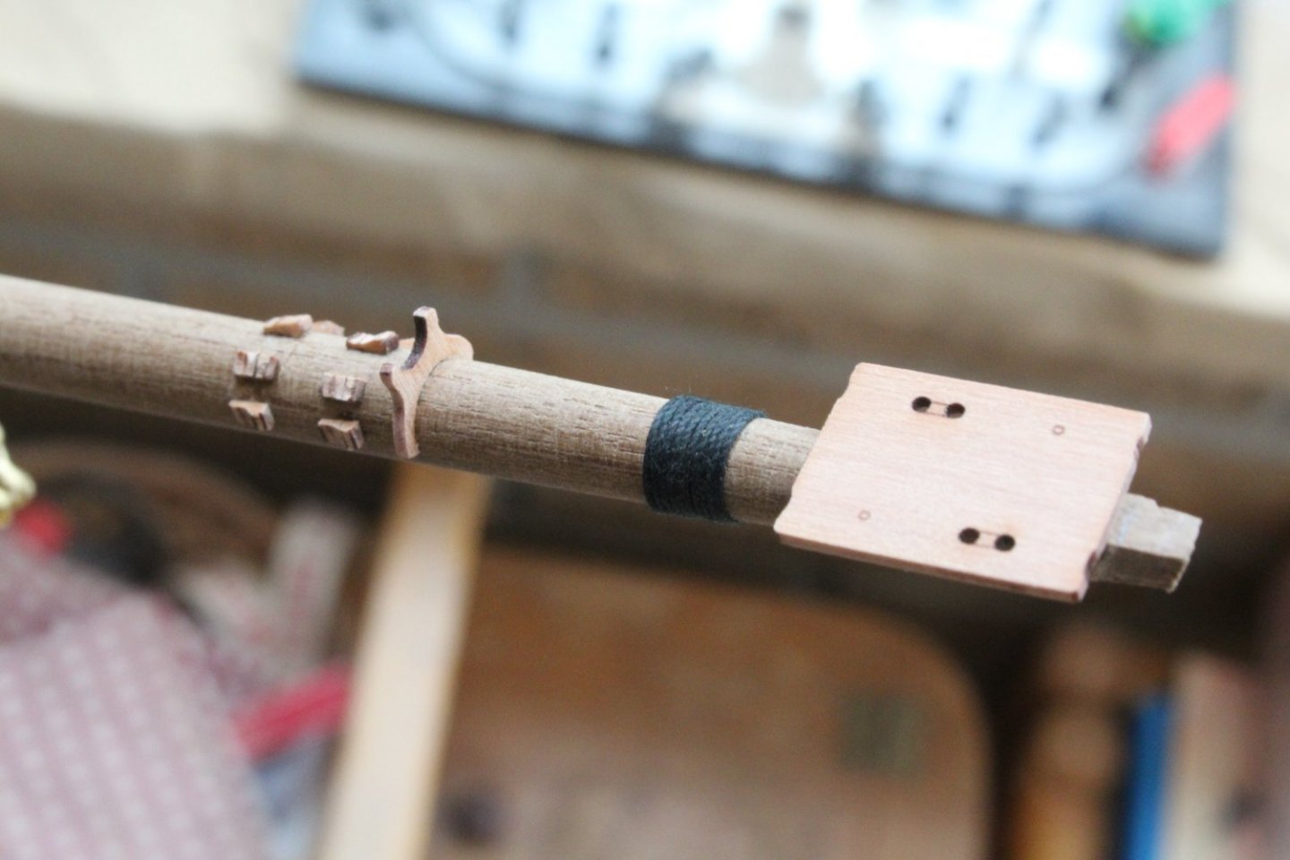
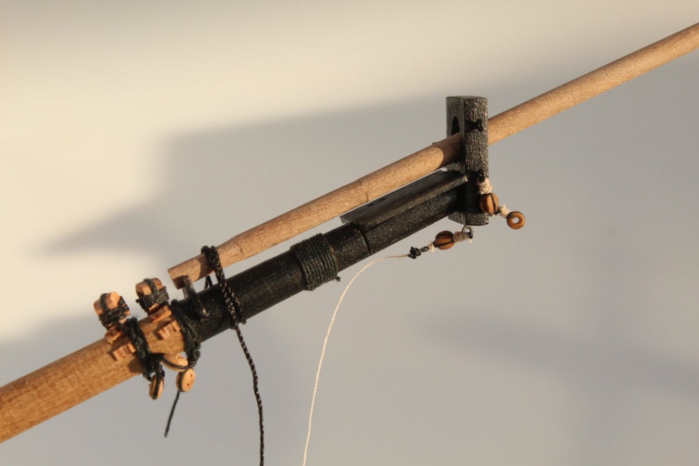
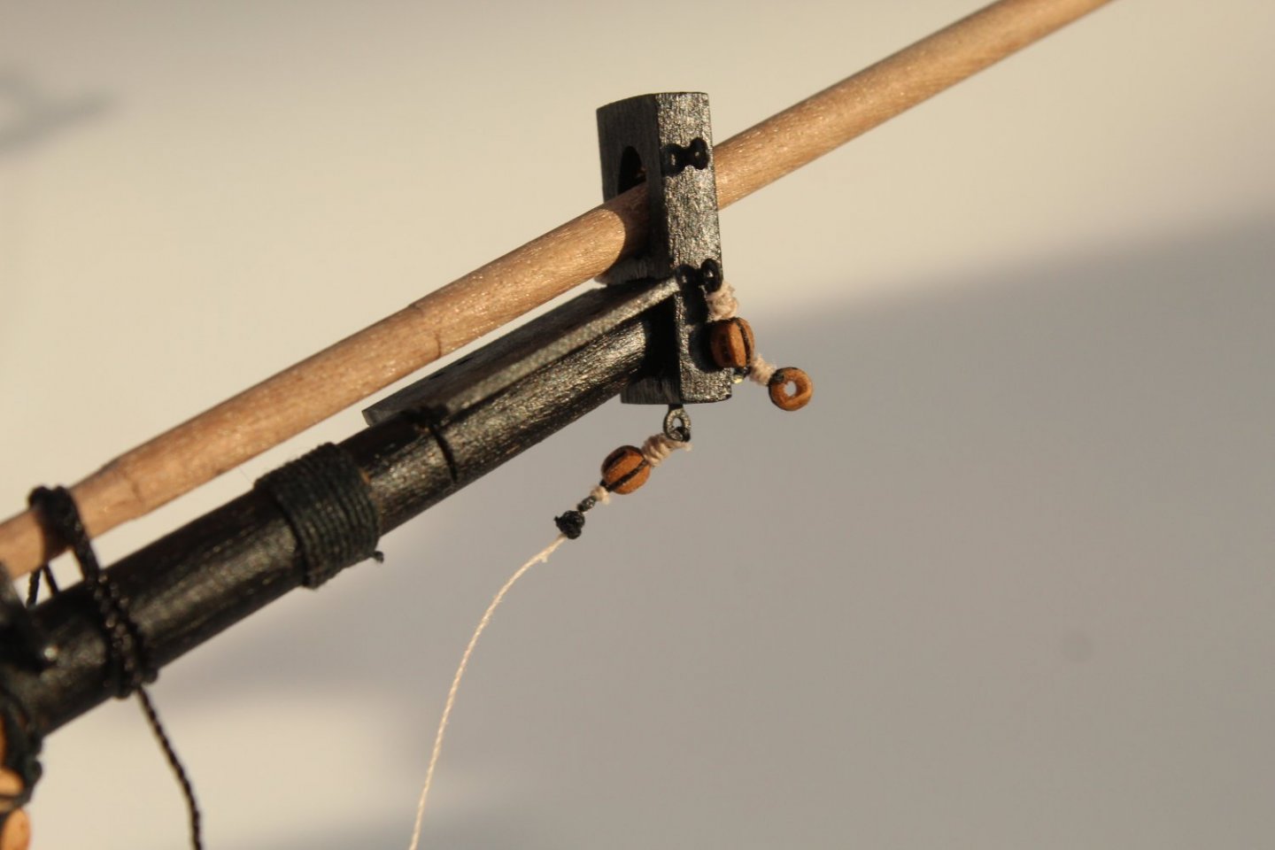
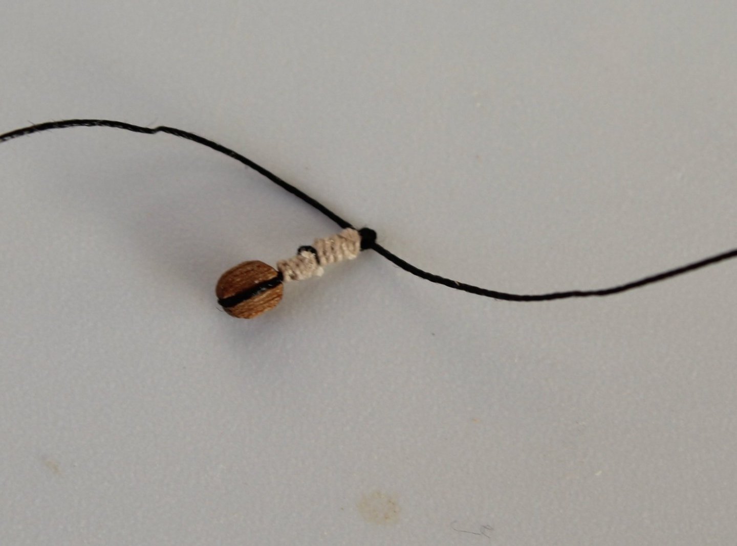
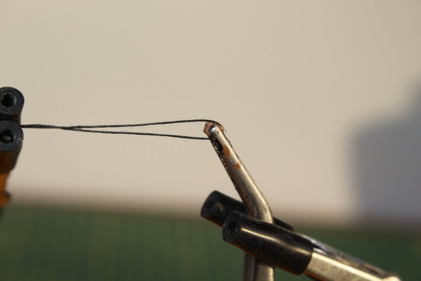
Spritsail and Spritsail topsail yard rigging This post covers the topic of rigging the spritsail and spritsail topsail yards, detailing some of the processes I used to complete this task. At the end of this post I have added some food for thought on the finished result. After I had secured the spritsail yard to the bowsprit I added the spritsail yard lift tackle rigging. This is where two single 3mm blocks are connected with a single length of thread, and when the thread is pulled the yard can be lifted in to place by the deckhands. One block is located centrally on the yard and the other block is located on the base of the bowsprit endcap. The rigged thread is seized to a ring on the base of the endcap block and is then fed through the hole on the spritsail yard block. From there the thread is then passed through the hole on the endcap block. Finally the end of the thread is belayed to a timberhead on the hull. A nice easy start to the rigging task. The photo below shows the spritsail yard lift line feeding through the fairlead and then belayed to a timberhead. Next up was to add the spritsail topsail yard to the jibboom. With the spritsail topsail yard lift tackle in place it was gently lifted in to place by the deckhands. I am not sure of the technical term for the rigging detailed in the next part of this post, possibly the braces for the spritsail yard? There is a pair of 3mm blocks that hang either side of the end of the jibboom and are positioned about halfway between the topsail and spritsail yards when fully tensioned. Threads from either side of the end of the spritsail yard are then fed through these blocks before being belayed to eyebolts located on the hull, next to each cathead. To enable to the thread to be secured to the block I added a ring when seizing the block, this is shown in the photo below. The thread is then fed through the ring on the first block and seized. This is shown in the photo below. With the first block fitted the thread was placed on the end of the jibboom the central point was marked, as shown in the photo below. This is to ensure both blocks look symmetrical when the rigging is complete. The second block is then added and the line adjusted, as necessary to ensure the blocks still look symmetrical. With everything looking good the rigging is completed when the line is belayed to eyebolt on the hull. In the photo below the line has been feed through the eyebolt and is ready to be seized. I have used a clamp used to hold in the line in place which I find make the seizing much easier. The next two photos shows the completed rigging of the two yards. On closer inspection of the completed rigging I have found some things which I am not totally happy with. As can be seen in the photo below I have indicated something which looks a bit messy. I need to see if I can straighten this mess up. A more worrying concern is one of the rigged lines has lost it's tension, as indicated in the photo below, I am not not sure how that has happened as I do know it was Ok when first rigged. The question I am now pondering is do I accept the rigging as is and move on or do I try to remove the completed rigging as necessary to resolve the issues. I know I should rip away and start again, but do I really want to throw away two days of hard work when overall it does not look to bad.


- 476 replies
-
- 7
-
-
- sphinx
- vanguard models
- (and 1 more)
-
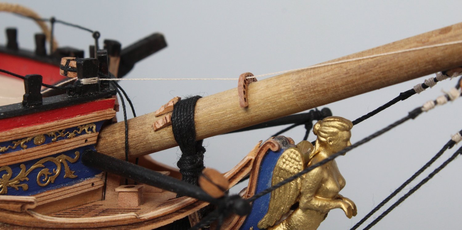
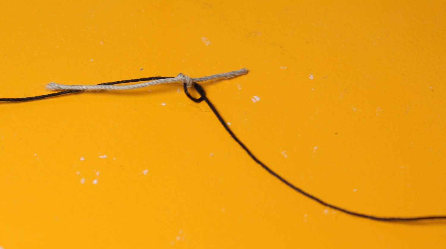
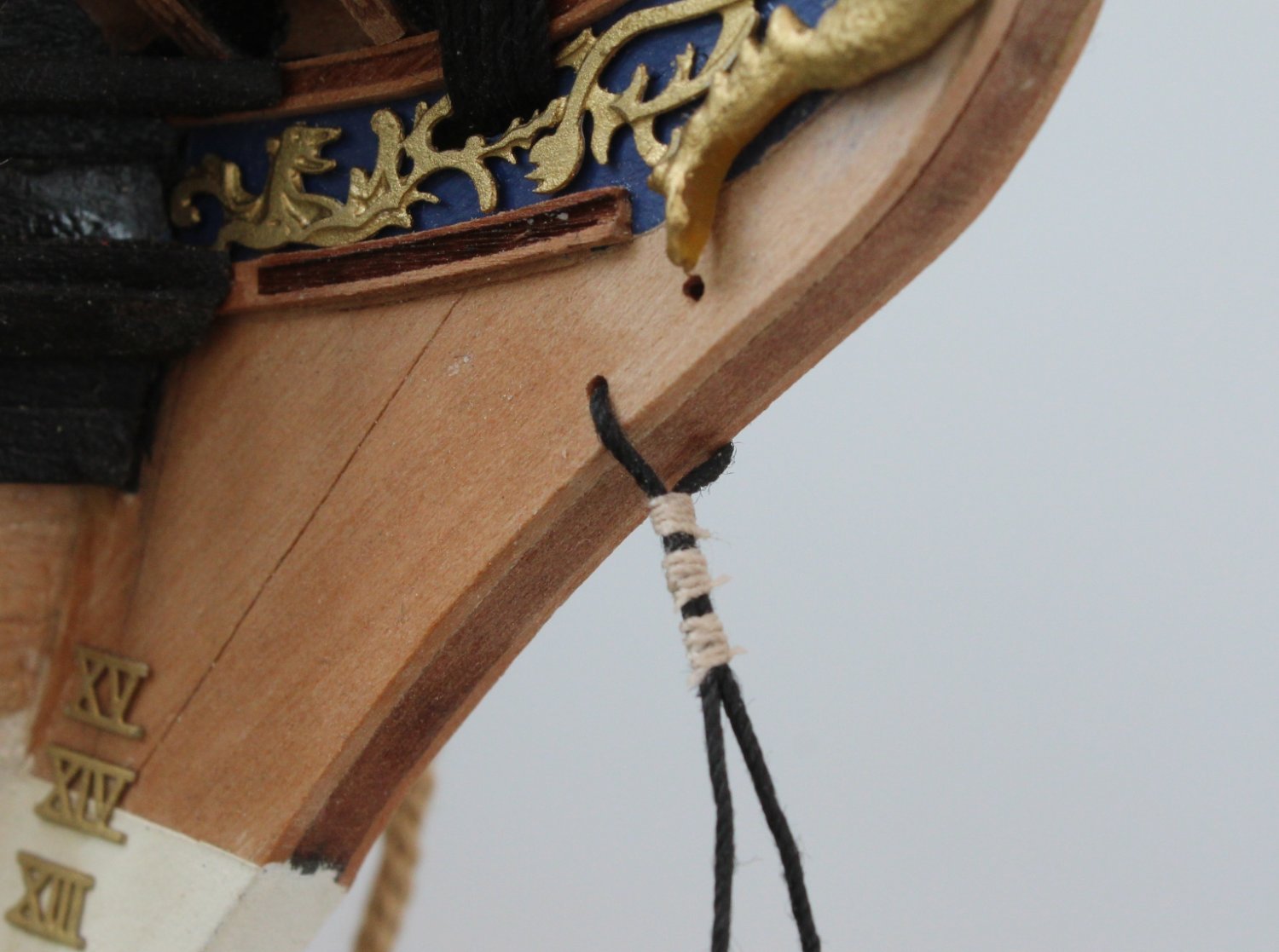
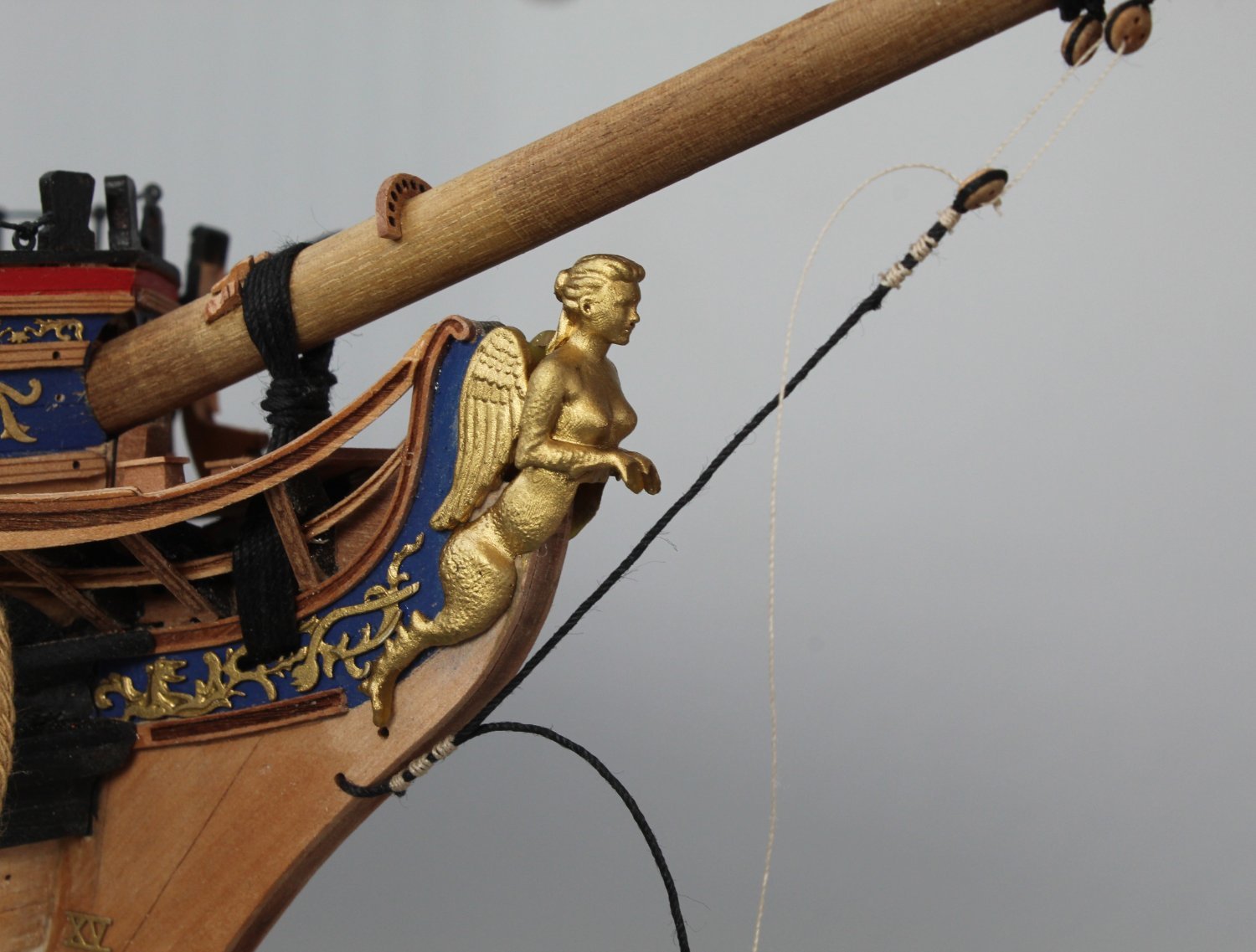
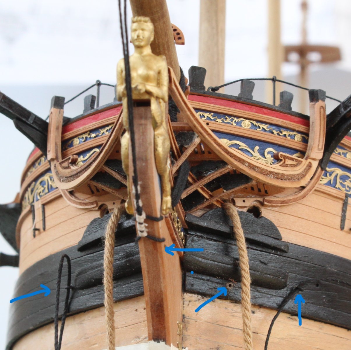
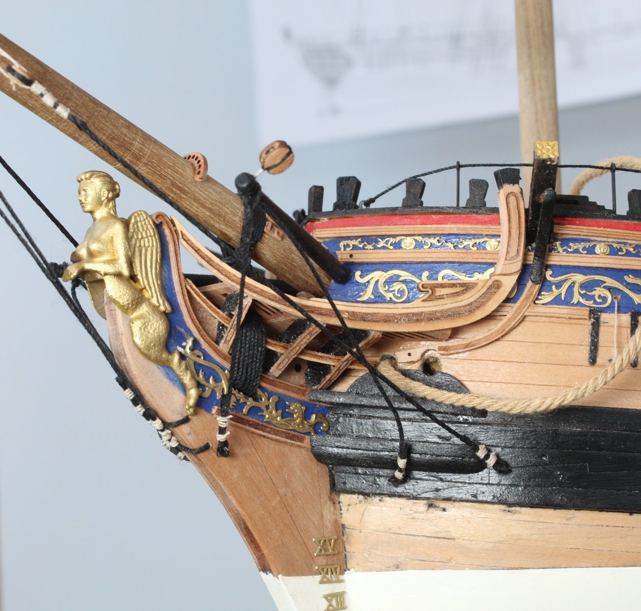
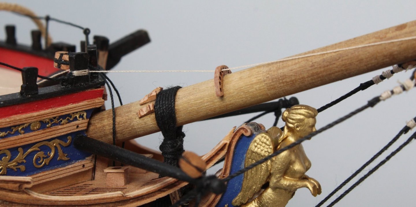
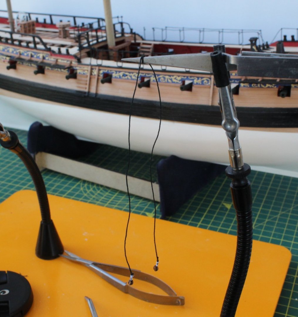
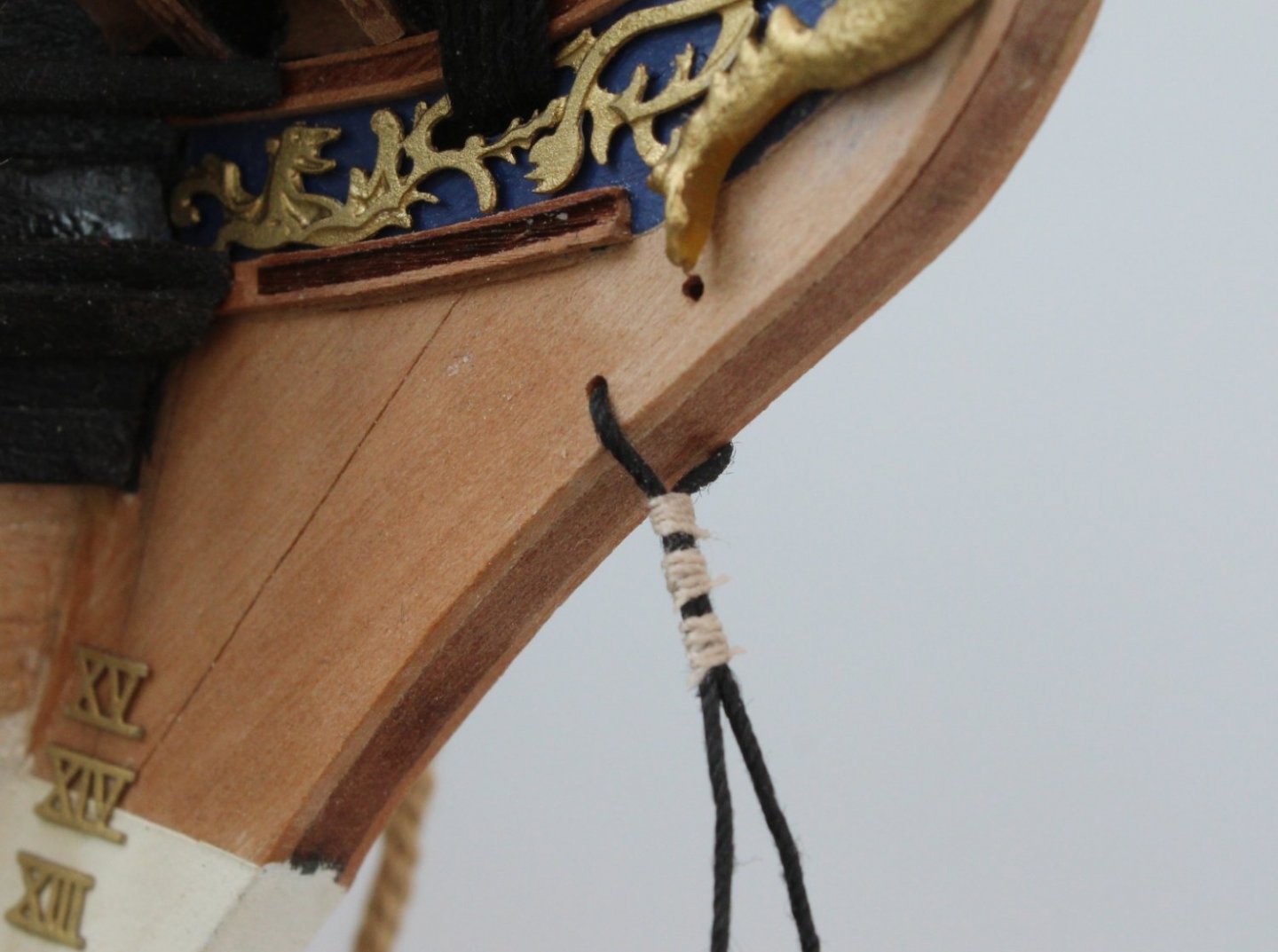
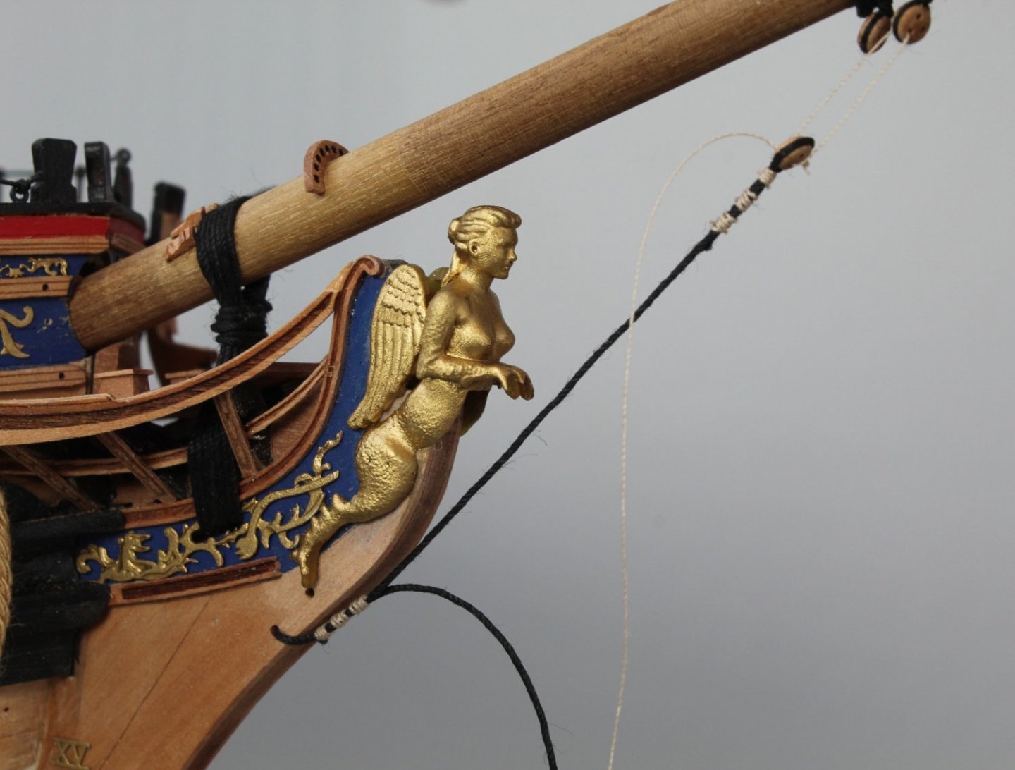
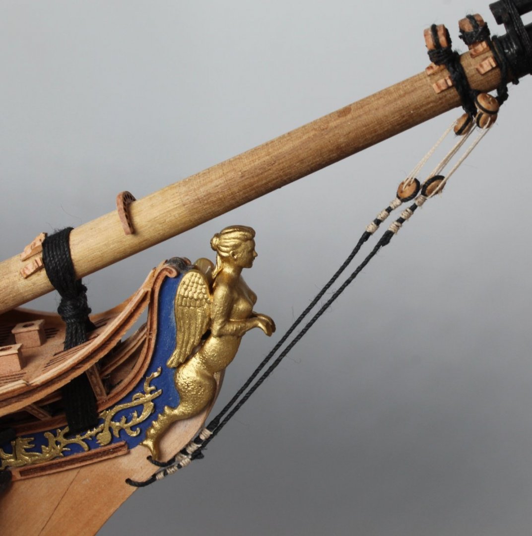
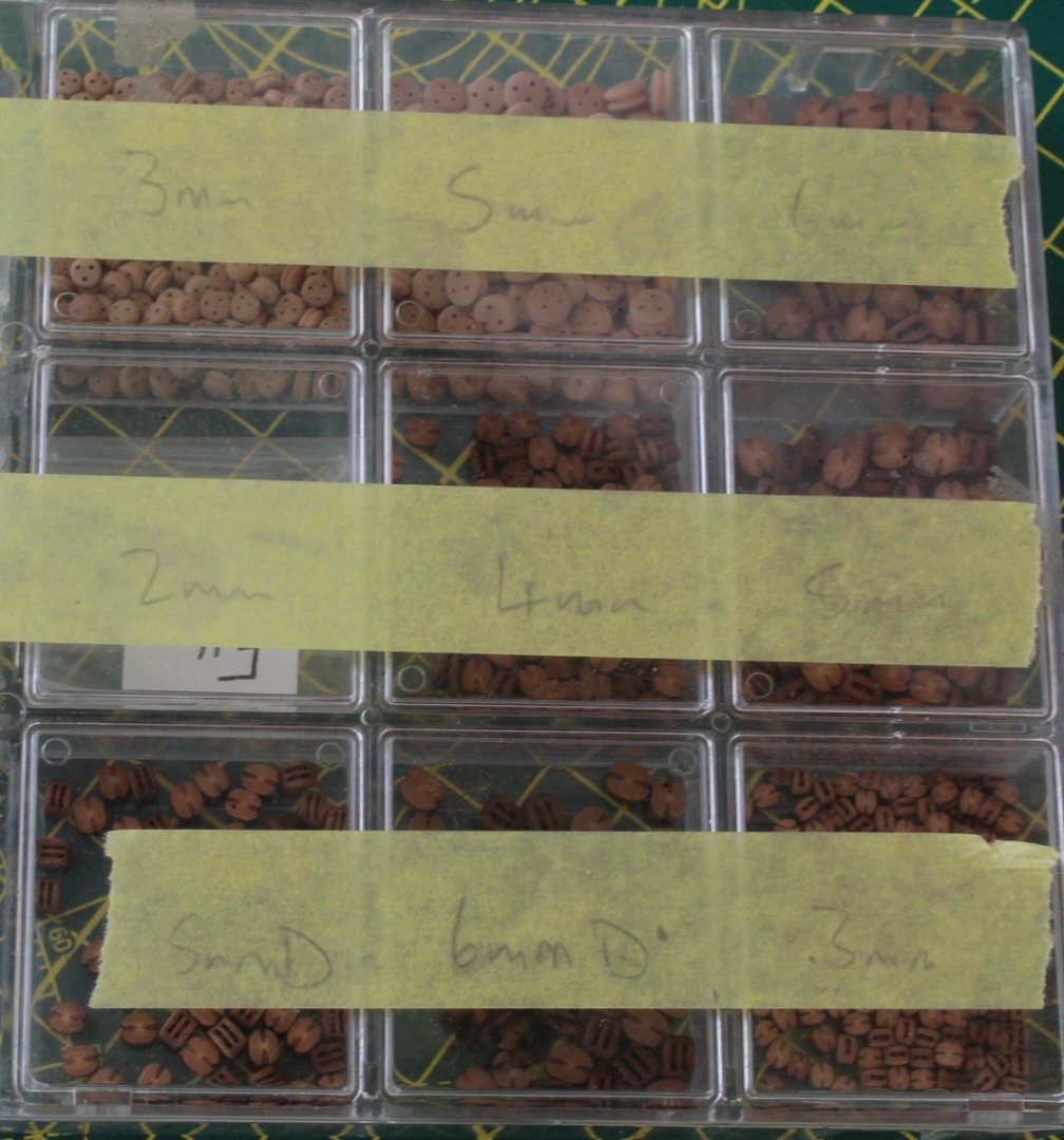
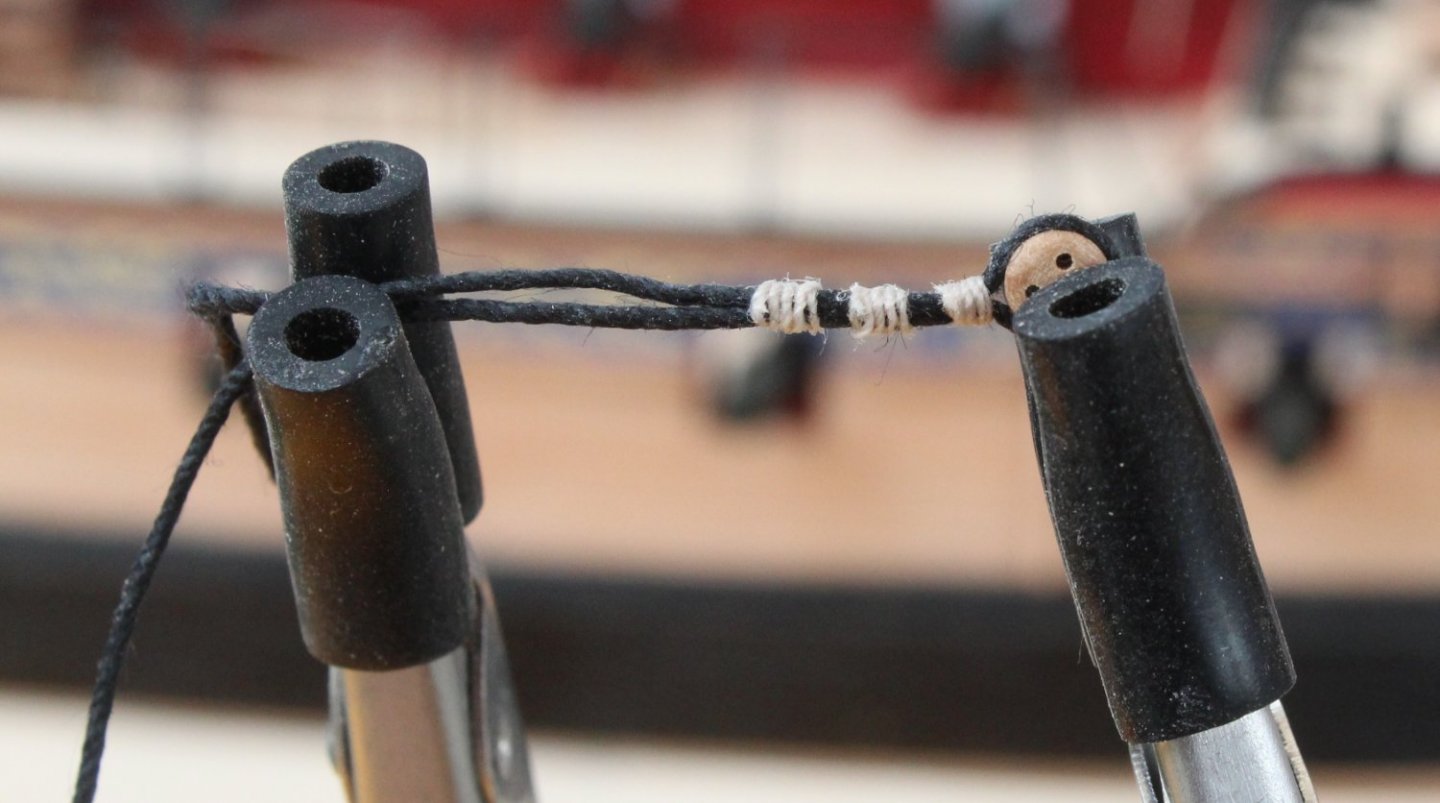
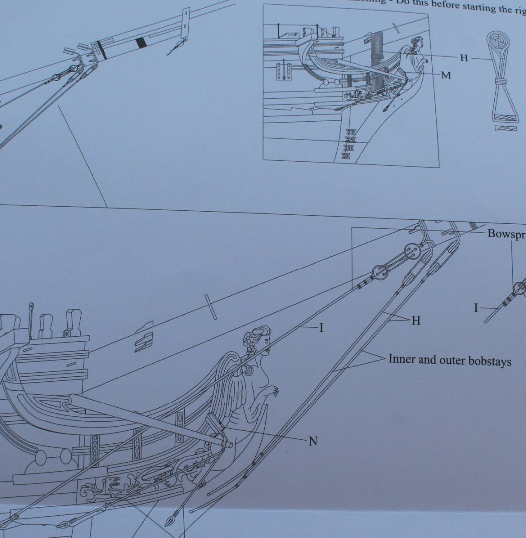
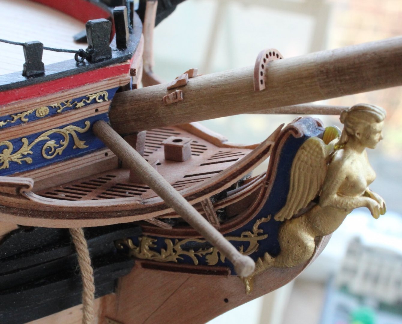
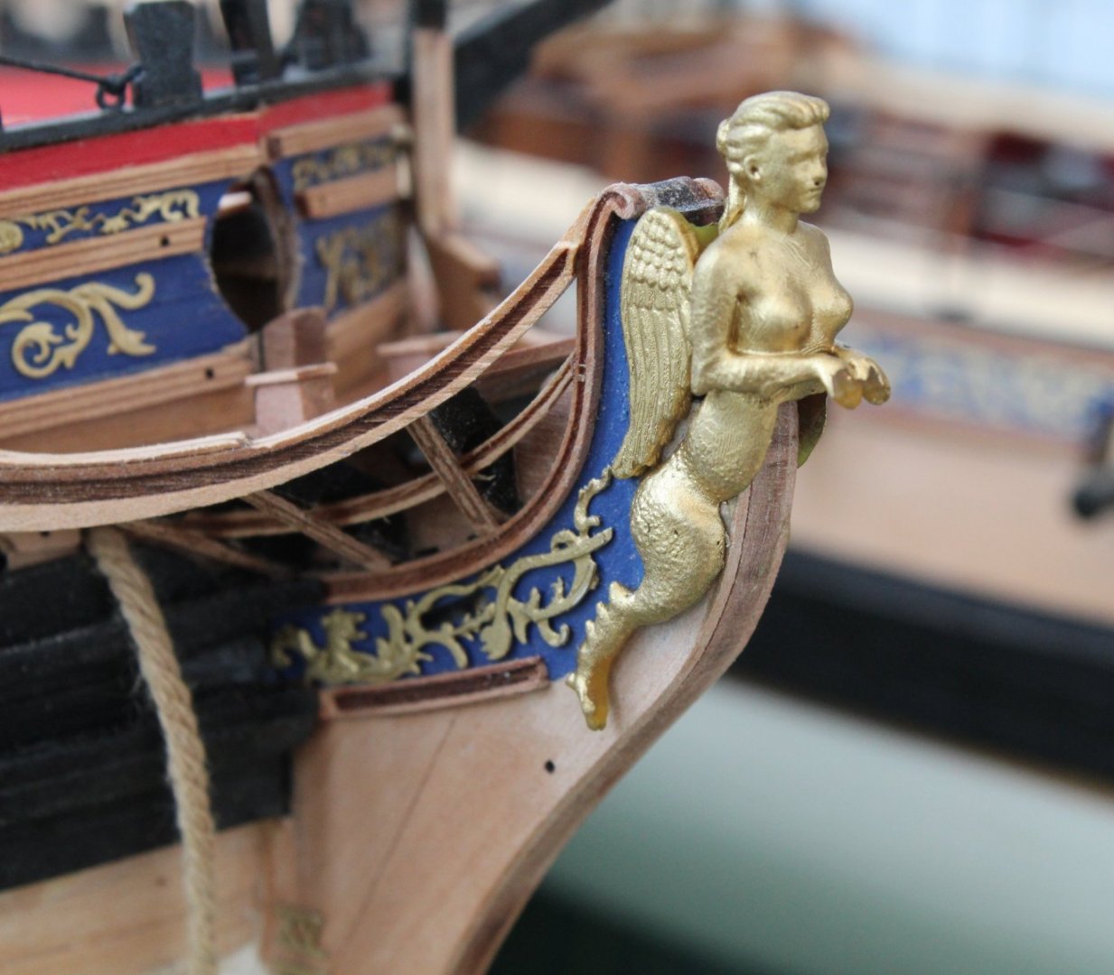
Bowsprit Stays, Shrouds, Boomkins and Main Collar Stay My very first model boat build was the AL Scottish Maid, and I have kept the small plastic box that was supplied with the kit, which is now used to store the various blocks I have collected on my various Vanguard model builds. Bob stays and bowsprit shrouds I cut 4 x 200mm lengths of the required black thread and seized a 3mm deadeyes to each thread in turn. The quad hands has become a must have tool as I do not know how I could attempt the rigging process without them. With the deadeye secured in the quad hands I can easily add a series of half hitch knots for the seizing. I added three separate seizing per deadeye, 4 turns per seizing. I also opted to use 0.1mm natural thread rather than the thinner fly tying thread for this task. It did not take long to add the deadeyes to the 4 lengths of thread. The following picture shows the deadeye held in the quad hands, with the seizing complete. The excess black thread is now ready to be trimmed. Once trimmed I do apply a touch of ca gel so the cut thread end and then I press it to the main thread line. In the photo below the first bob stay line has been secured to the stem post. I took my time to adjust the position of the stay seizing so that the deadeye was in the required position. The photo below was taken just after I had started to rig the first lanyard and shows the entire stay and lanyard. The figurehead is keeping her eye on my work to make sure it passes muster. I was very pleased with how the first bob stay turned out. The stay is nicely tensioned. The deadeyes and lanyards are not twisted and I think the figurehead approves of my work. The second stay was then added, once again the deadeyes and lanyards are not twisted. I should have added a bit more tension to the 2nd stay when adjusting the lanyards but overall it is not to bad. The next task was to prepare the hull for the bowsprit shrouds and boomkins. Holes were drilled in readiness for adding the eyebolts. As can be seen in the photo below the bowsprit shroud eyebolt has been fitted and the two shroud lines fed through them. I did end up running a 1mm microdrill through the bowsprit shroud deadeyes before fitting as I found it impossible to pass the 1mm black thread through eyebolt hole. I must be on a roll as the bowsprit shroud deadeyes and lanyards are installed without any twisting and the lines are nicely tensioned. Boomkins The next photo shows the method I used to hold the thread in place to allow me to seize the boomkin thread to the eyebolt in the stem post. You will note I have already seized the other end of the thread to the hull mounted eyebolt. The boomkin line shown below looks a bit slack near the hull mounted eyebolt, but I can live with that for my build. Main Collar Stay The final task completed was to add the main collar stay block. The threads were passed though the holes on the bow grating, next to the seats of comfort. I then pass one line through the hole provided in the stem post and added the seizing beneath the grating and is out of sight. I will be moving on to rigging the spritsail yard and spritsail topsail yard next. Once that is complete it I will fabricate the main and fore masts.


- 476 replies
-
- 5
-
-
- sphinx
- vanguard models
- (and 1 more)
-
Thanks. I do refer to the pdf version which I keep on my laptop. I have also downloaded the photos in Jim's build log which really helps as I can focus in on key areas of interest.
- 476 replies
-
- 2
-
-
- sphinx
- vanguard models
- (and 1 more)
-
Hello Chris I understood your instructions on the rigging sheet regarding when the pendants should be added. It was simply a complete lack of understanding on my part as to what function a burton pendant served. I wrongly assumed it was another rigging line where the thimble end would be rigged to either a deadeye, block, eyebolt or belaying pin, etc. I failed to comprehend these were simply used as hoisting tackle lines and would should be left to dangle.
- 476 replies
-
- 4
-
-
- sphinx
- vanguard models
- (and 1 more)
-
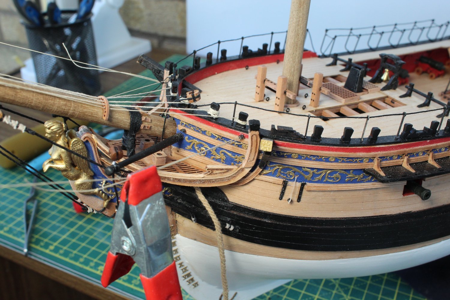
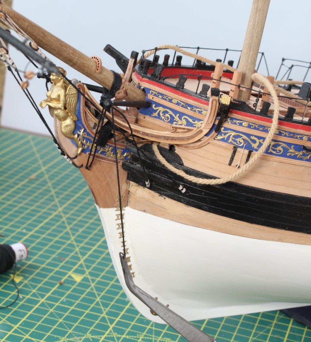
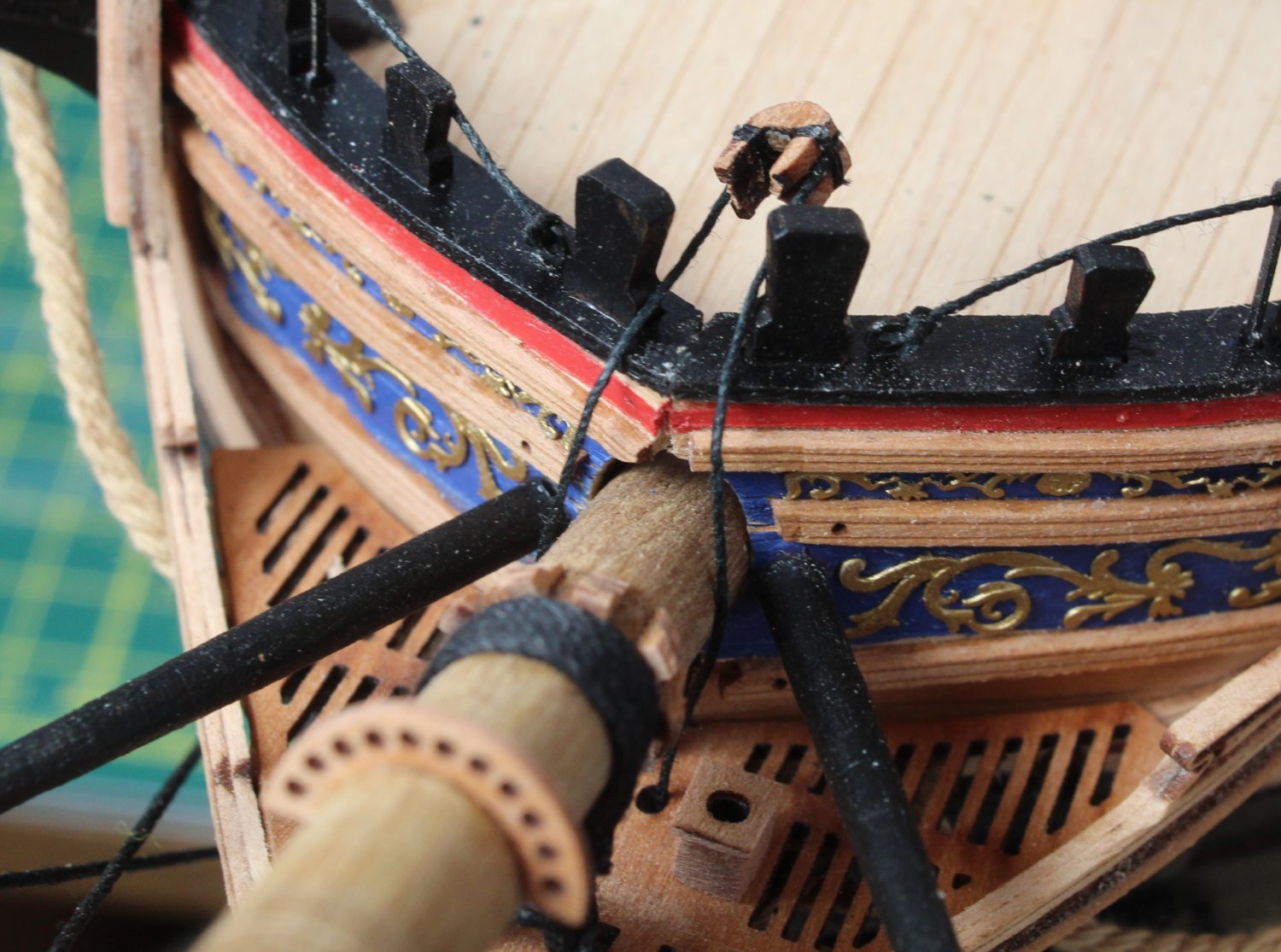
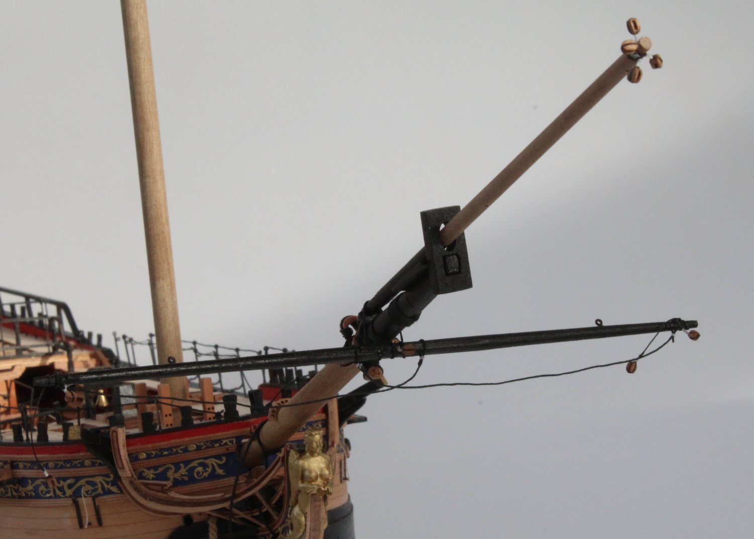
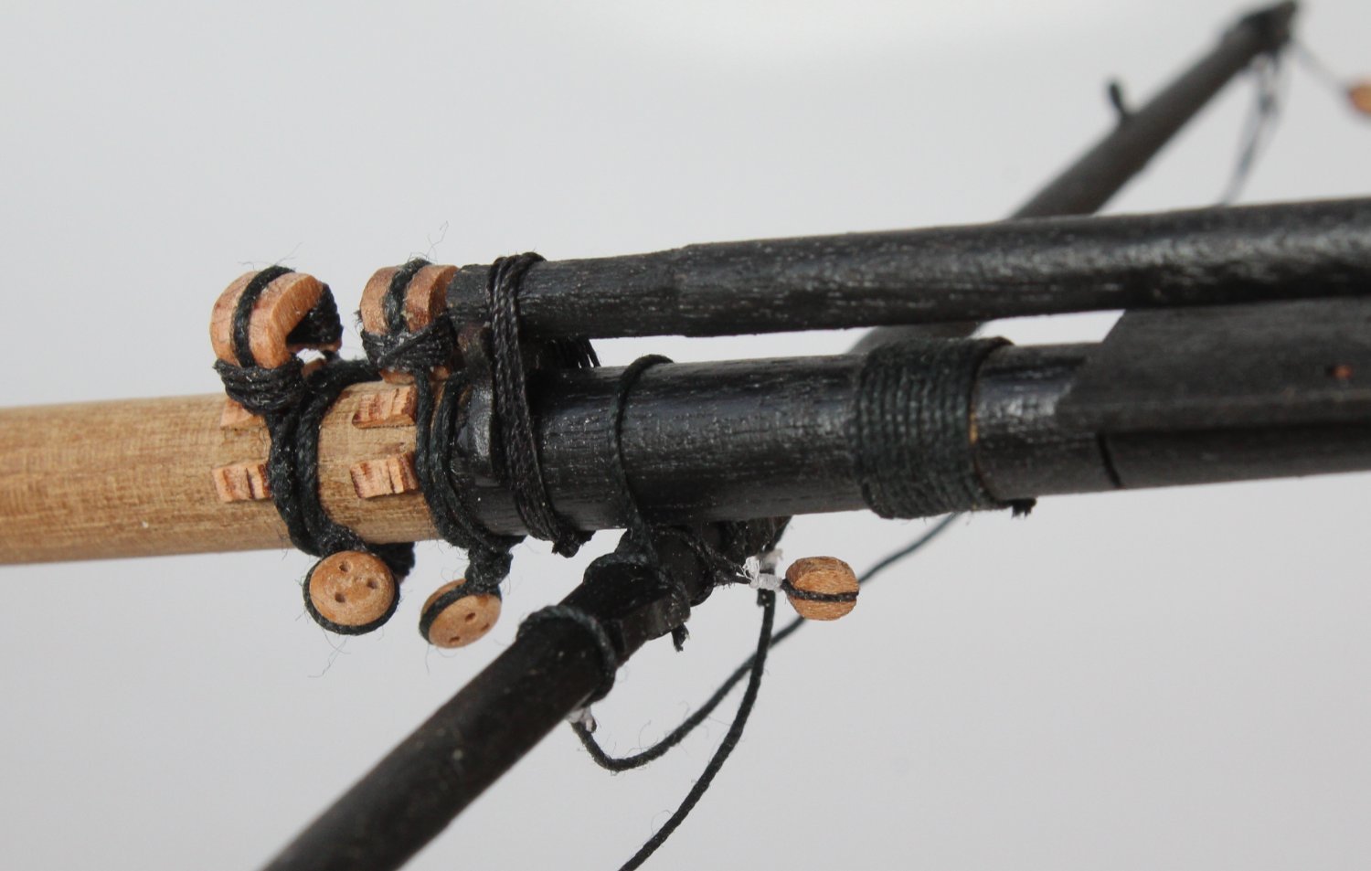
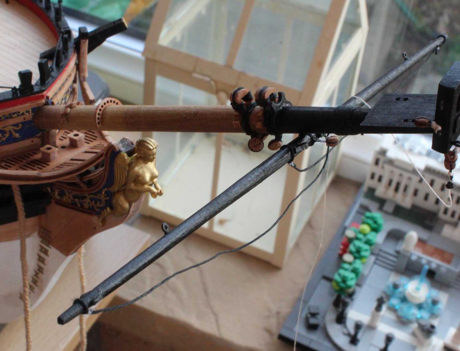
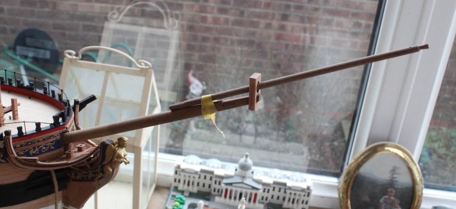
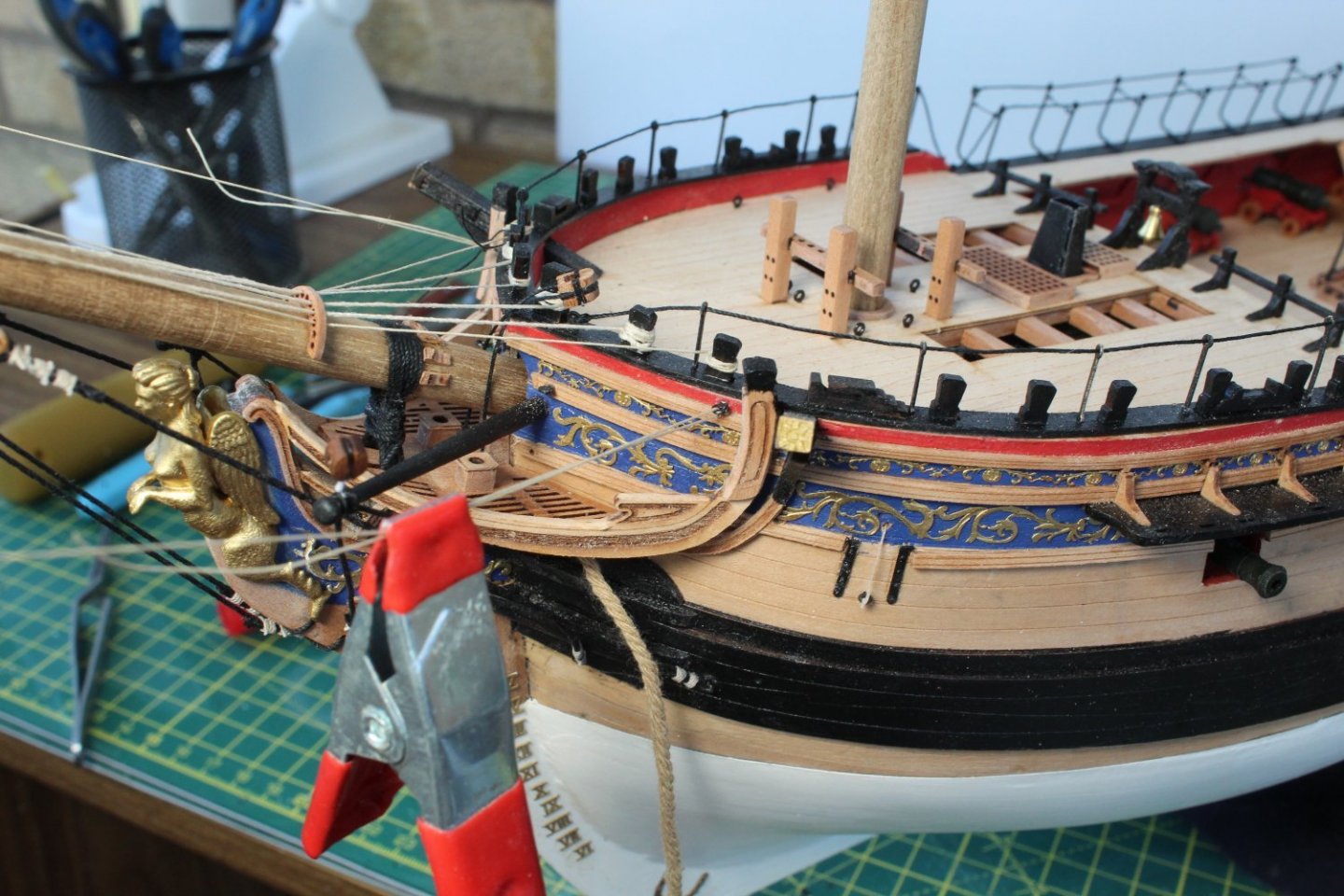
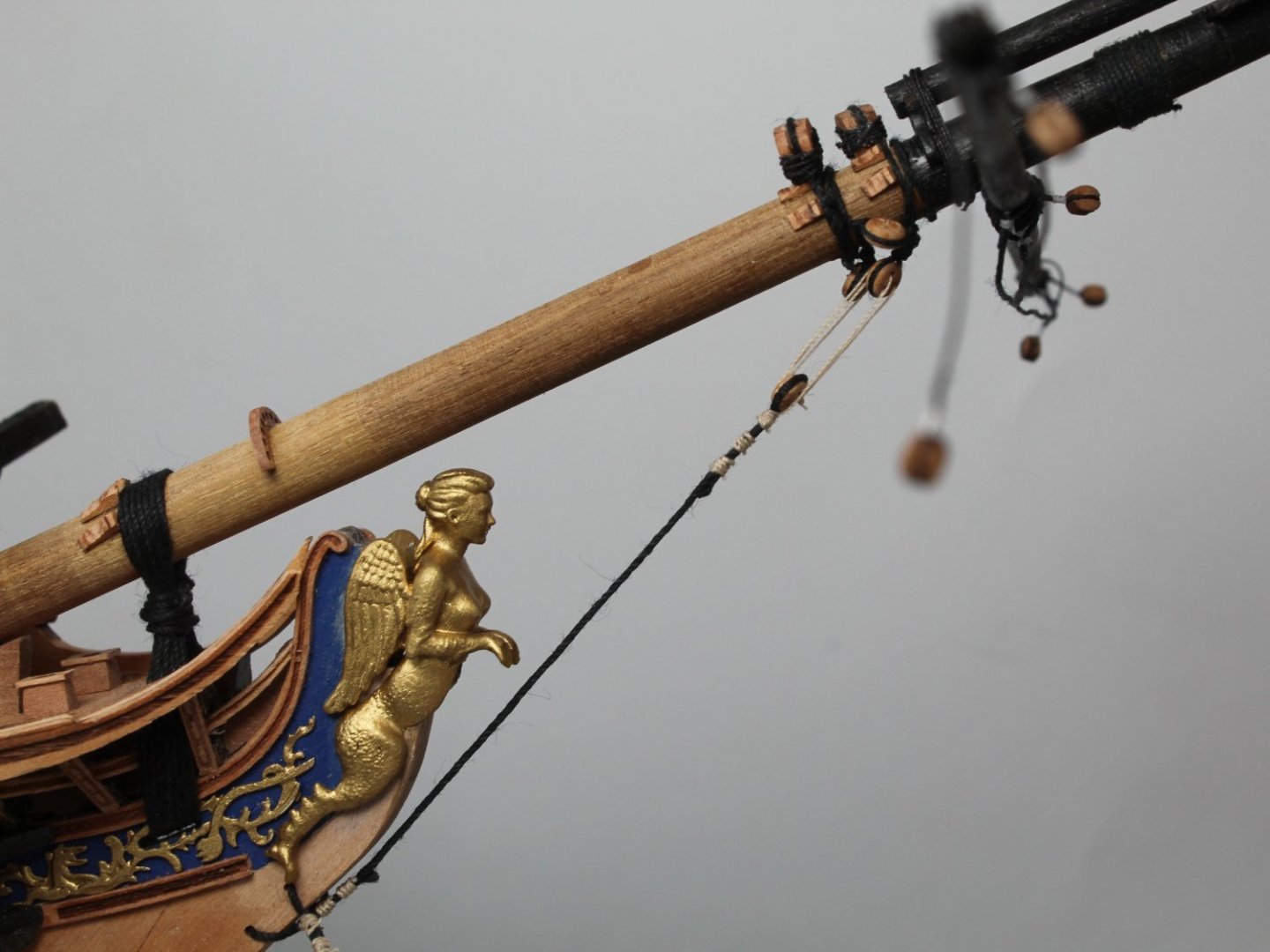
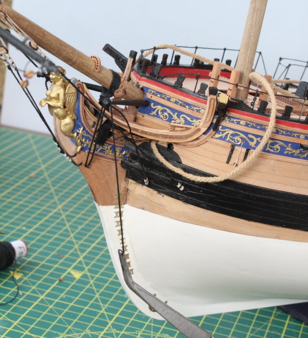
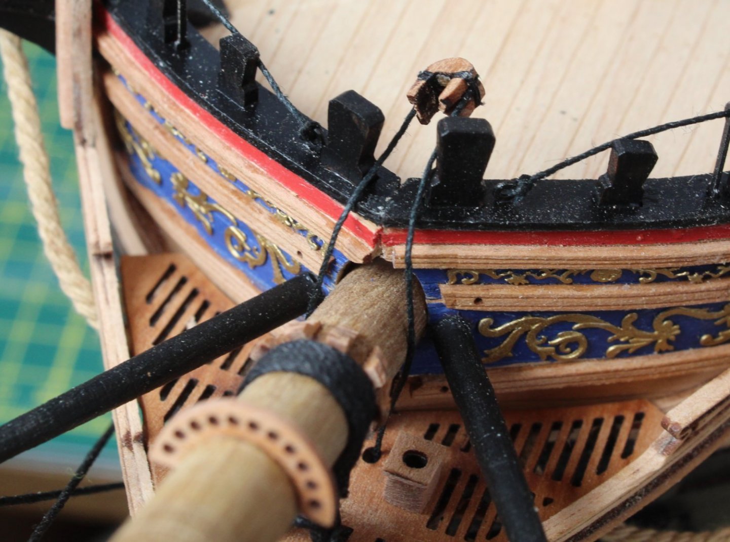
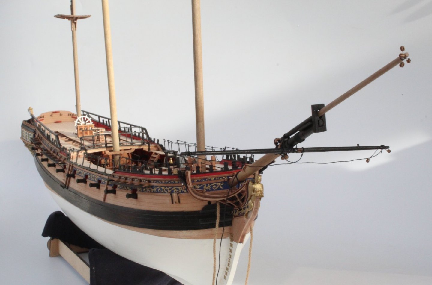
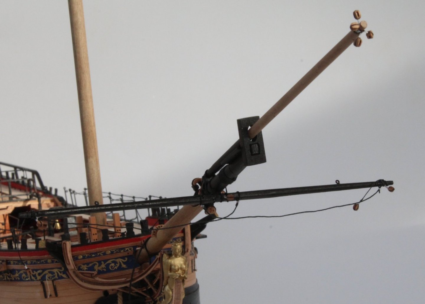
Bowsprit Work Continues The bowsprit complete with the jibboom and spritsail yard has now been installed. I will add the boomkins and spritsail topsail yard later on once the gammoning, bob and fore bowsprit stays have been rigged. The Sphinx is starting to take shape, but there is still a long way to go. The spritsail yard is looking good. I am really happy with how the various spritsail yard blocks look and they are correctly positioned and aligned in readiness for the rigging. The next photo is a close up of the spritsail yard and jibboom where they are secured to the bowsprit. I opted to fit the spritsail yard to the jibboom before adding them to the bowsprit. I did find this much easier to do off the boat. I started to add the gammoning and it appeared to be going well. Thankfully I took a break and realised I had made a fundamental error in that I was looping the thread under the bow grating without taking it through the slot in the stem post, as can be seen in the photo below. I have restarted the gammoning, this time I am passing the thread through the stem post slot. As can be seen in the photo below I made a loop hole to get the gammoning thread secured to the bowsprit. Once the gammoning is complete I plan to add the fore and bob bowsprit stays. I spent last night studying the rigging plans and ended up on a wild goose chase. On the first rigging sheet it advises that the burton pendants should be added to the mizzen, main and fore masts before the shrouds. I then spent about 15 minutes looking over the 4 rigging plan sheets to see where the thimbles ends should be rigged / belayed to. I could not seem to find any other reference to them on the plan sheets and began to think that Chris had simply missed something off the rigging sheets. I then searched through the photos on Jim Hatch's build log and the pictures in the build manual and I could not seem to find a clear picture that would help me. I was becoming very frustrated. Eventually I found a post on MSW where @Blue Ensign provided the answer, see the bold red italic text below. My very limited knowledge base on rigging period ships is slowly expanding. They are the first item of rigging over the mastheads and are used to attach tackles for heavy lifting. This can be by a thimble spliced into the end of the pendant into which a tackle is hooked, or by a block spliced into the end. They are followed over the masthead by the shrouds, back stays where appropriate, and finally the stays.

- 476 replies
-
- 7
-
-
- sphinx
- vanguard models
- (and 1 more)
-
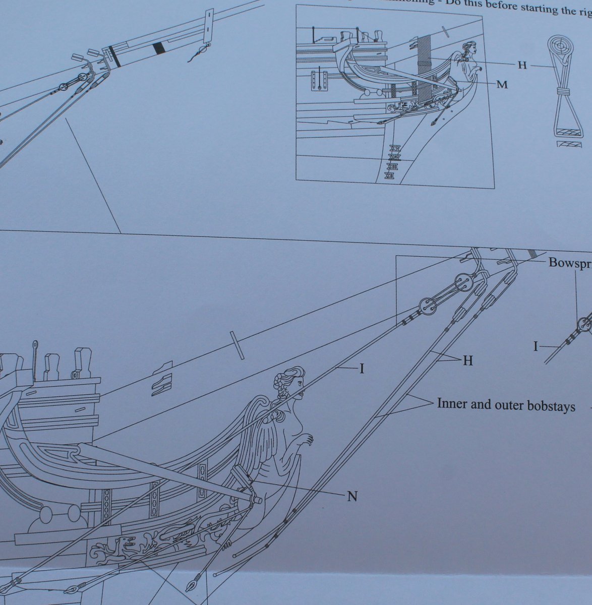
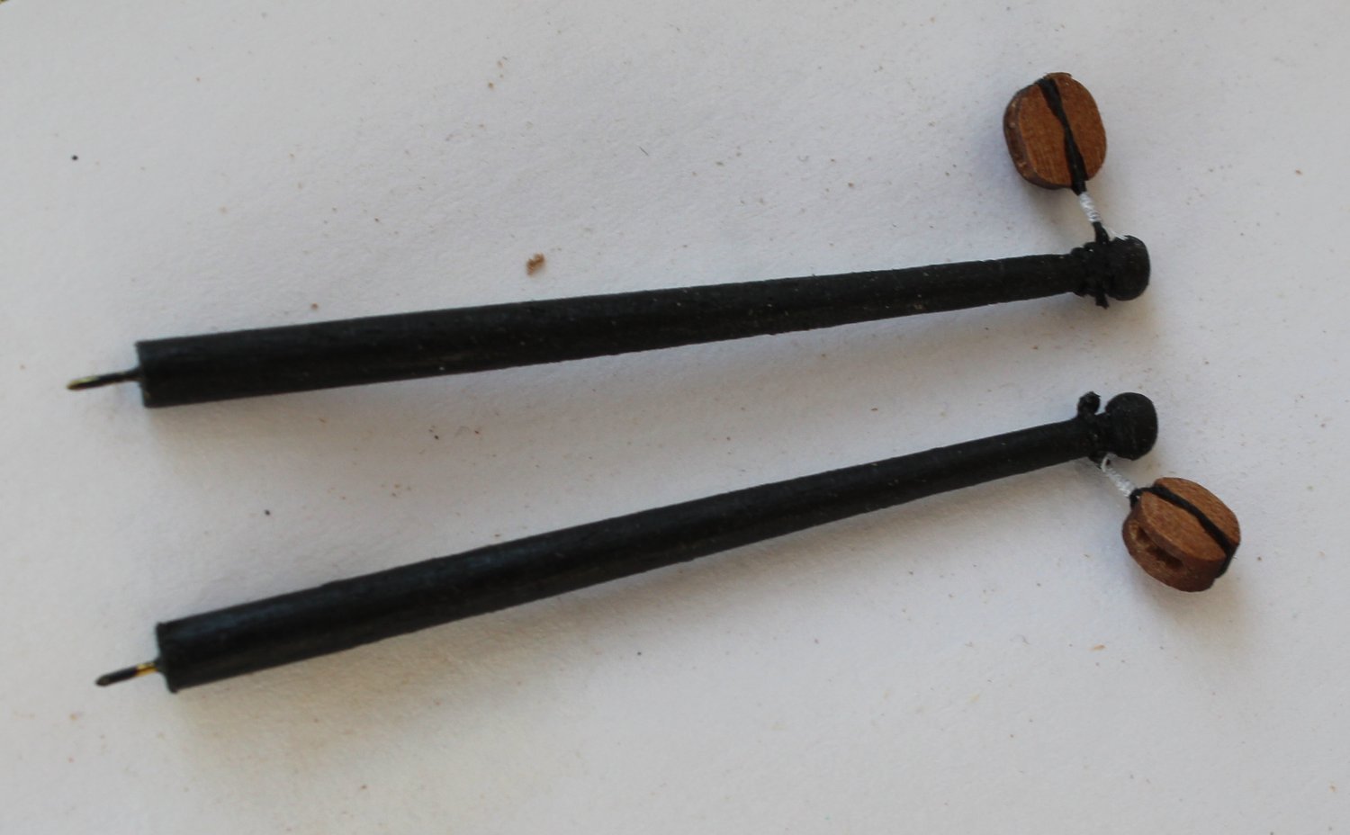
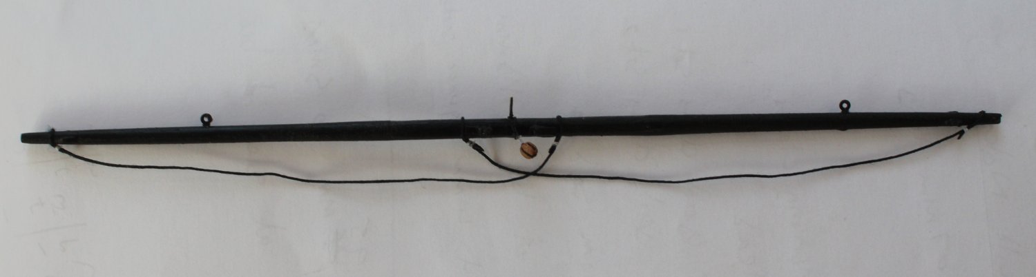
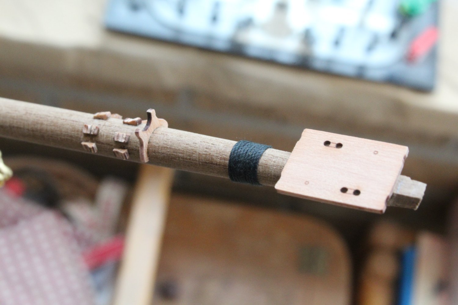
Bowsprit Work Status I will be in position to start the bowsprit rigging tomorrow, as detailed in the rigging plan sheets. I think I start by add the spritsail yard to the bowsprit as I think it will be easier to this before fitting the jibboom. I will then secure the spritsail topsail yard to the jibboom before I secure the jibboom to the bowsprit. Once everything has been secured I will glue to bowsprit assembly in place. I also have an idea to make the rigging of the bowsprit deadeye a bit easier which I may try out. I will detail the method should my idea prove to workable. Moving on here is an update of all the work I have undertaken on the bowsprit, jibboom, spritsail yard, spritsail topsail yard, and 2 x boomkins. Jibboom I have now completed the work on adding the 4 off 3mm single blocks to the end of the jibboom. I am very happy with the end result. I did take time to ensure the blocks were correctly aligned, as detailed on the plan sheets. This should make the rigging task much easier and neater. Before adding the blocks I will refer to the rigging plans for the thread size and then I like to check to see if I can feed the thread through the block holes. I usually find it necessary to run a suitable sized micro drill through the block holes to slightly enlarge the holes. In the photo below I have a 0.25mm thread passing through a 3mm single block and a 0.75mm thread passing through a 5mm single block. Boomkin The basic shaping of the two boomkins was relatively straight forward, I decided round off the end, as can be seen in the photo below where the boomkins were test fitted to the hull. There is a single block to be added to the end of each boomkin. When referring to the rigging plans it refers to a type M (5mm single block) on insert section and a type N (6mm block) just below the the insert. Chris did confirm this should be a 5mm single block. The boomkins have been painted black and the 5mm single blocks have been added, in the correct orientation. The boomkins are now ready to be added to the hull and rigged. Spritsail Topsail Yard A length of 3mm dowel was tapered from 2.5mm at the centre point of the dowel down to 1.5mm at each end. The 6 cleats were added and the yard painted black. Finally I added the required threads. A pin was also added to allow the spritsail topsail yard to be secured to the jibboom. The yard has not been glued to the jibboom in the photo below, which was just being test fit. You will also note the end of the jibboom has also been painted black. Spritsail Yard This started life as a length of 4mm dowel. The dowel was tapered down to 1.8mm to each end with a hexagonal shaping added to the central section. The various cleats were added and the yard painted black before the threads, central 3mm single block and two eyebolts were added. A securing pin was has also been added. The spritsail yard has been test fitted to the bowsprit in the next photo I just need to add 4 x 3mm single blocks, two to each end of the spritsail yard to complete the work on the spritsail yard. I have prepared the first two blocks, using the technique I detailed in my previous post, using flying thread for the whipping and I have opted to add 10 loops per block.


- 476 replies
-
- 6
-
-
- sphinx
- vanguard models
- (and 1 more)
-
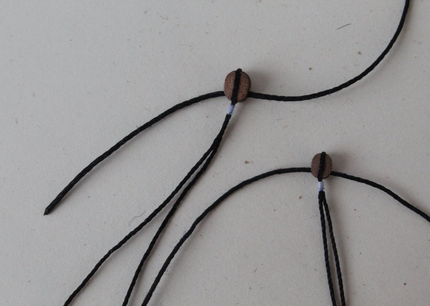
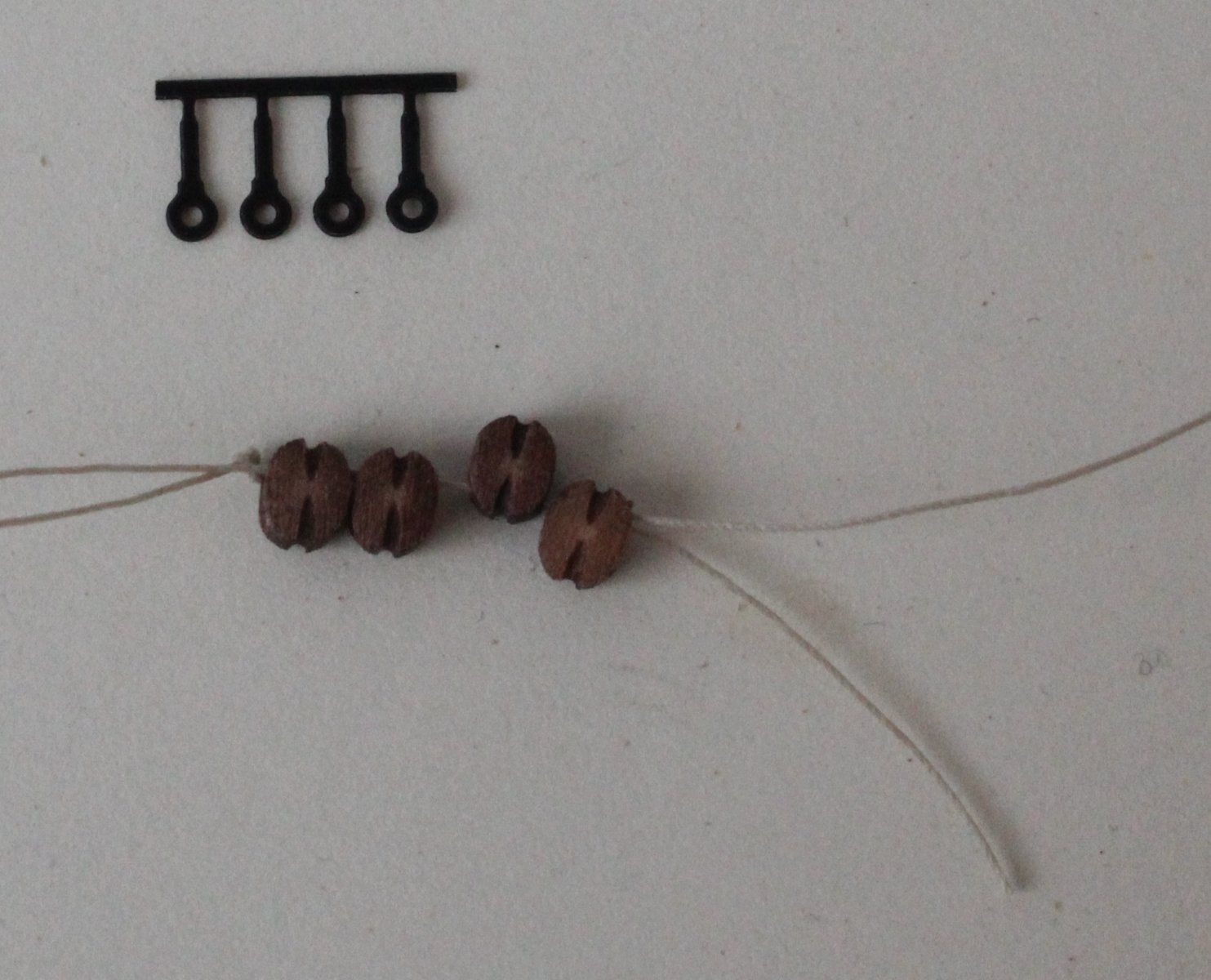
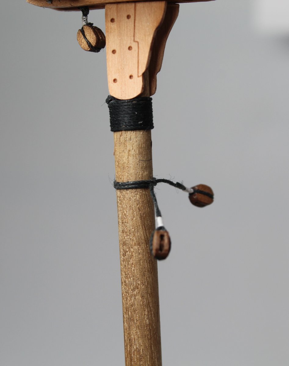
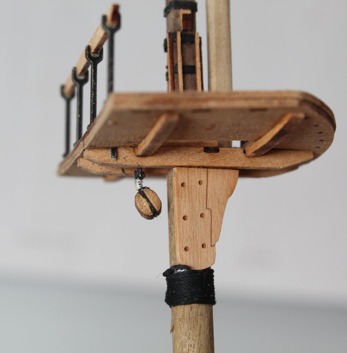
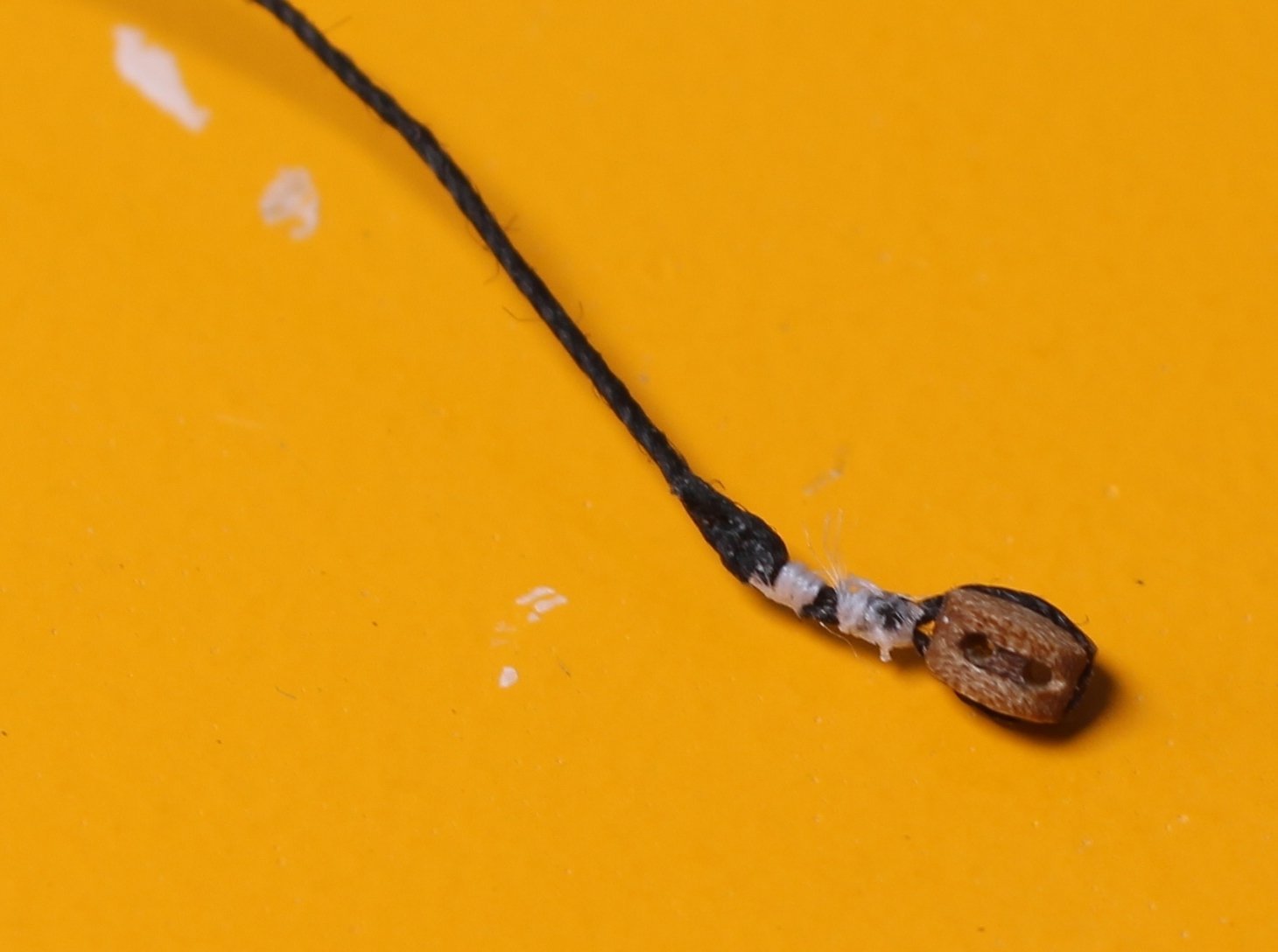
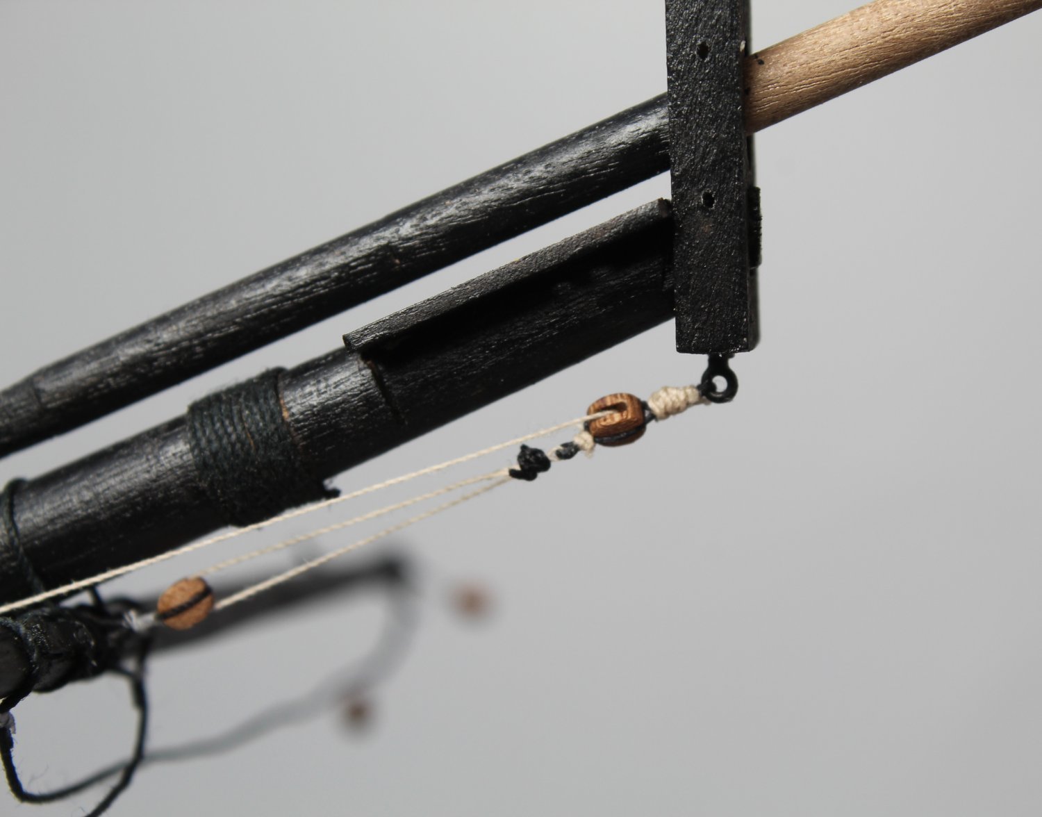
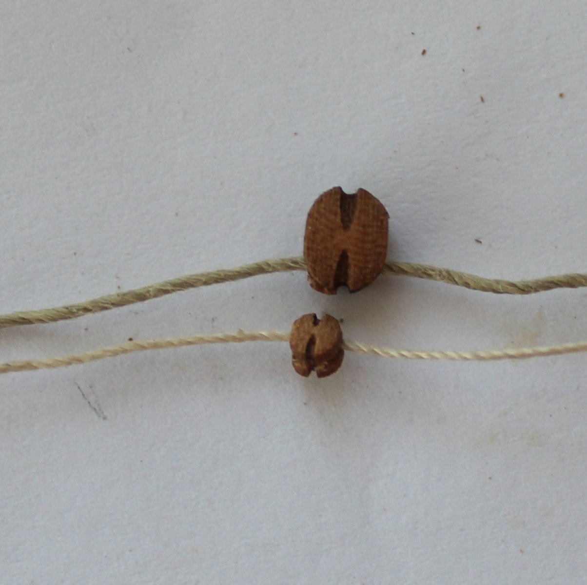
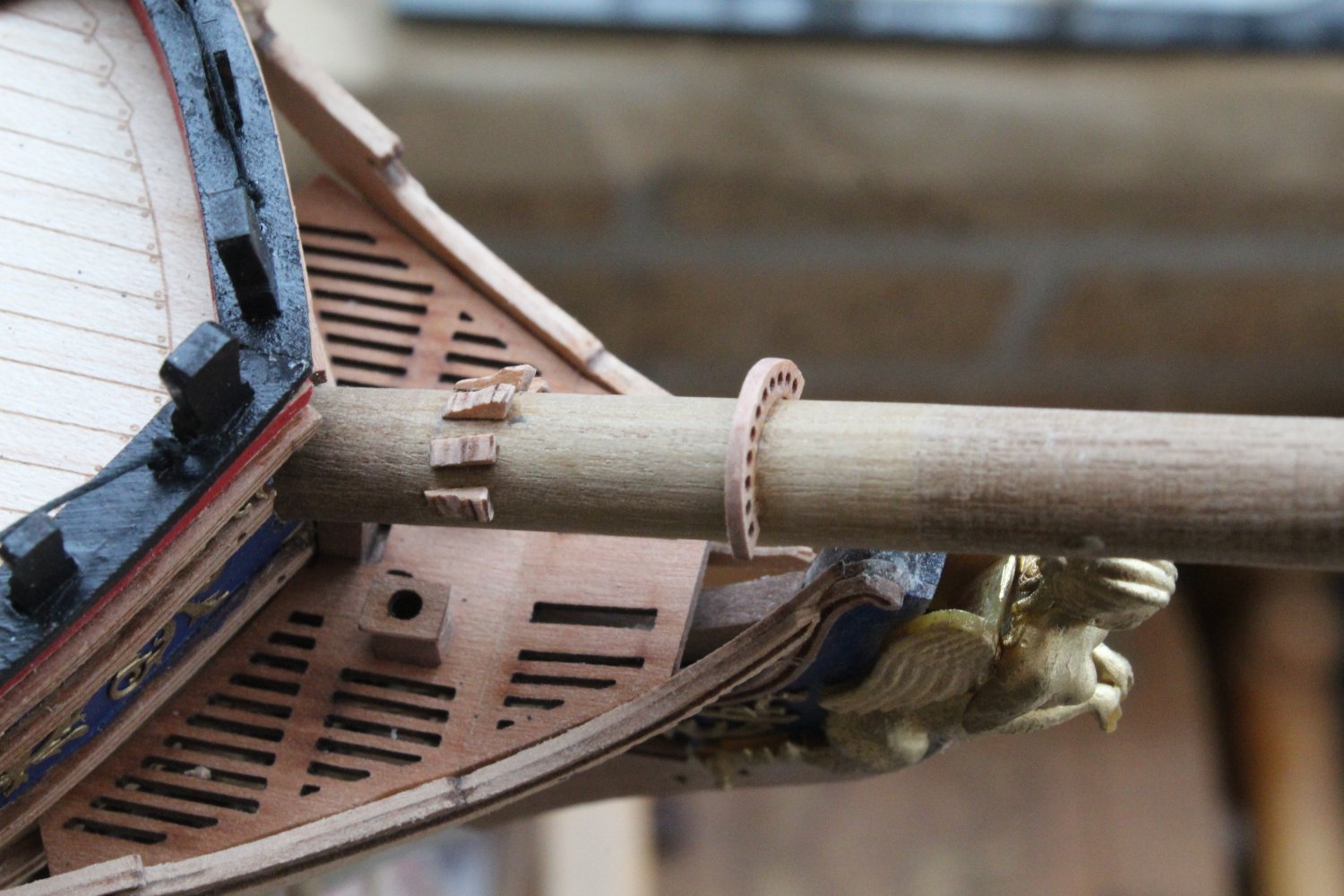
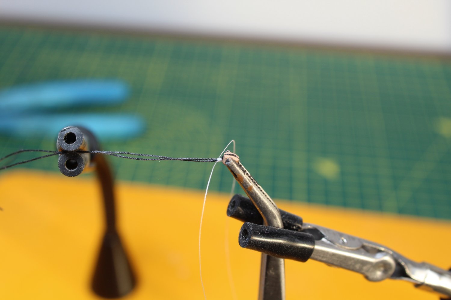
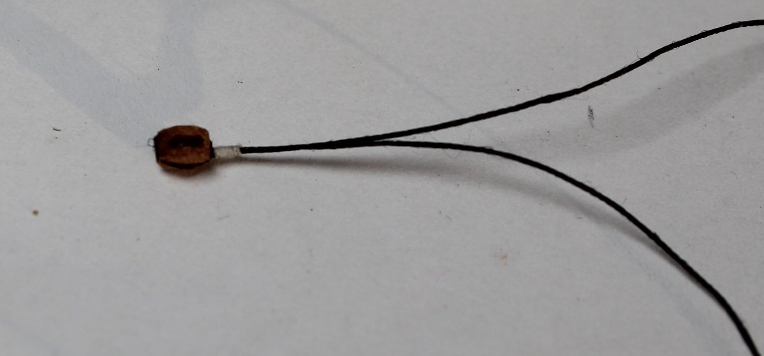
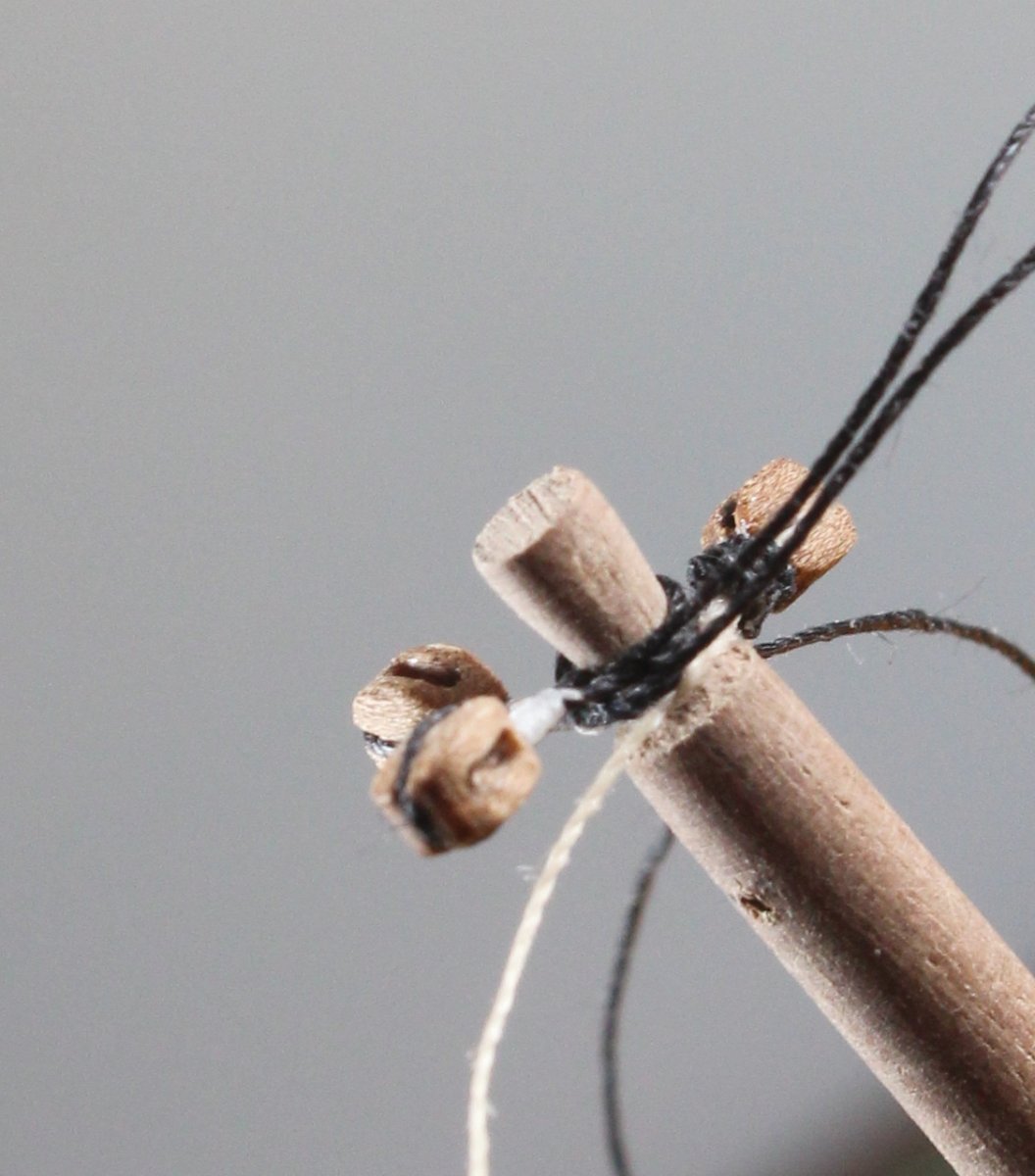
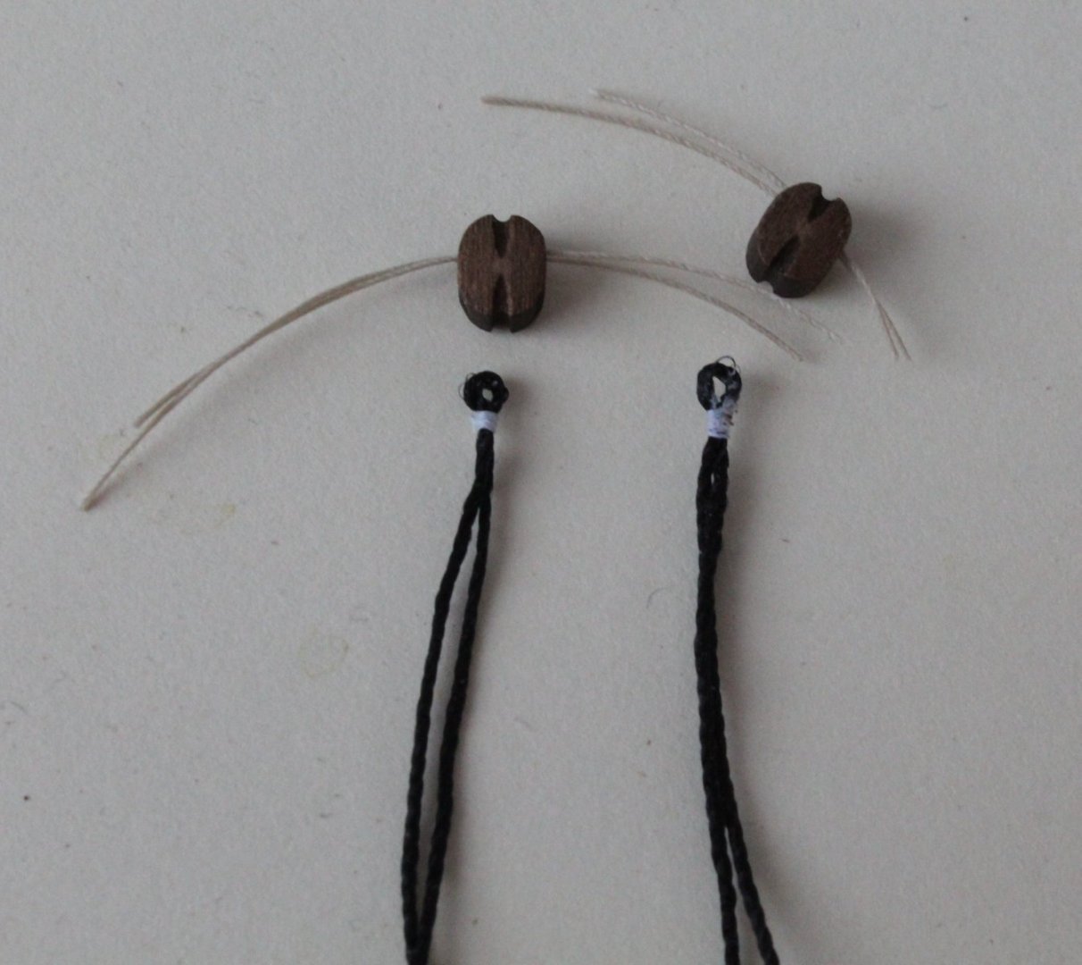
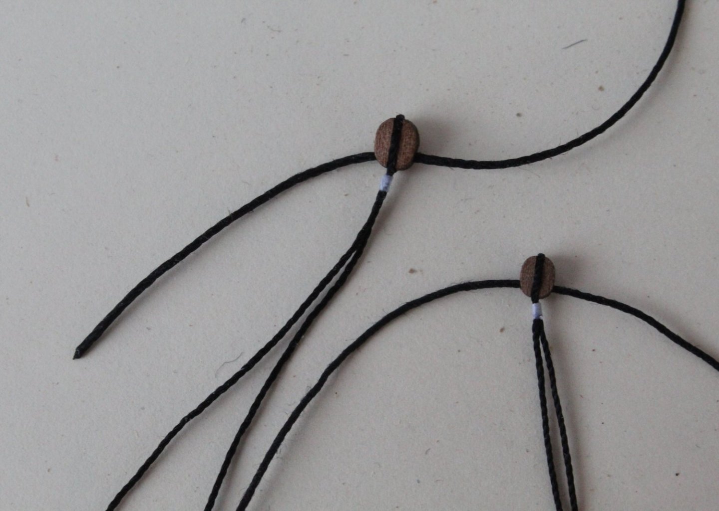
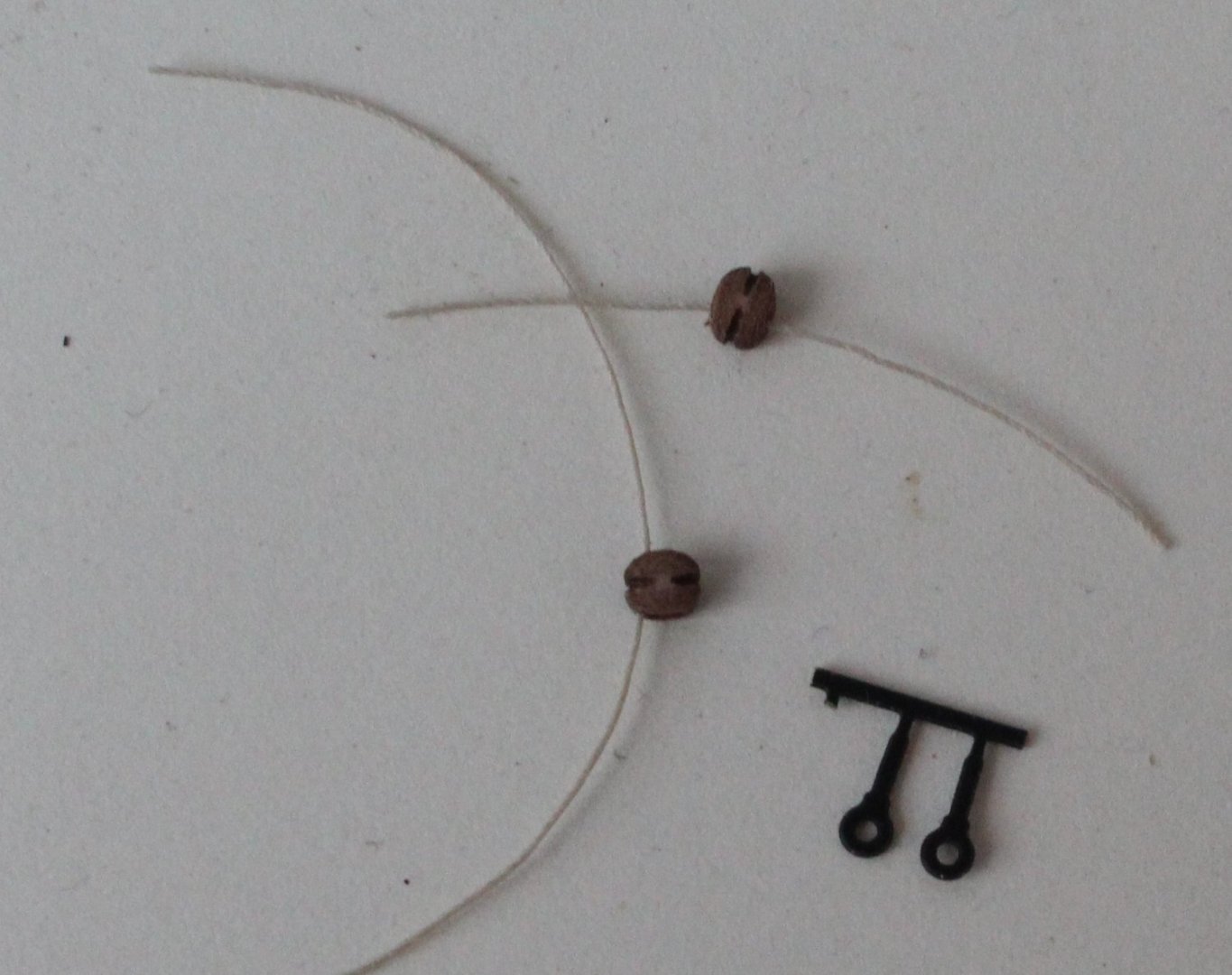
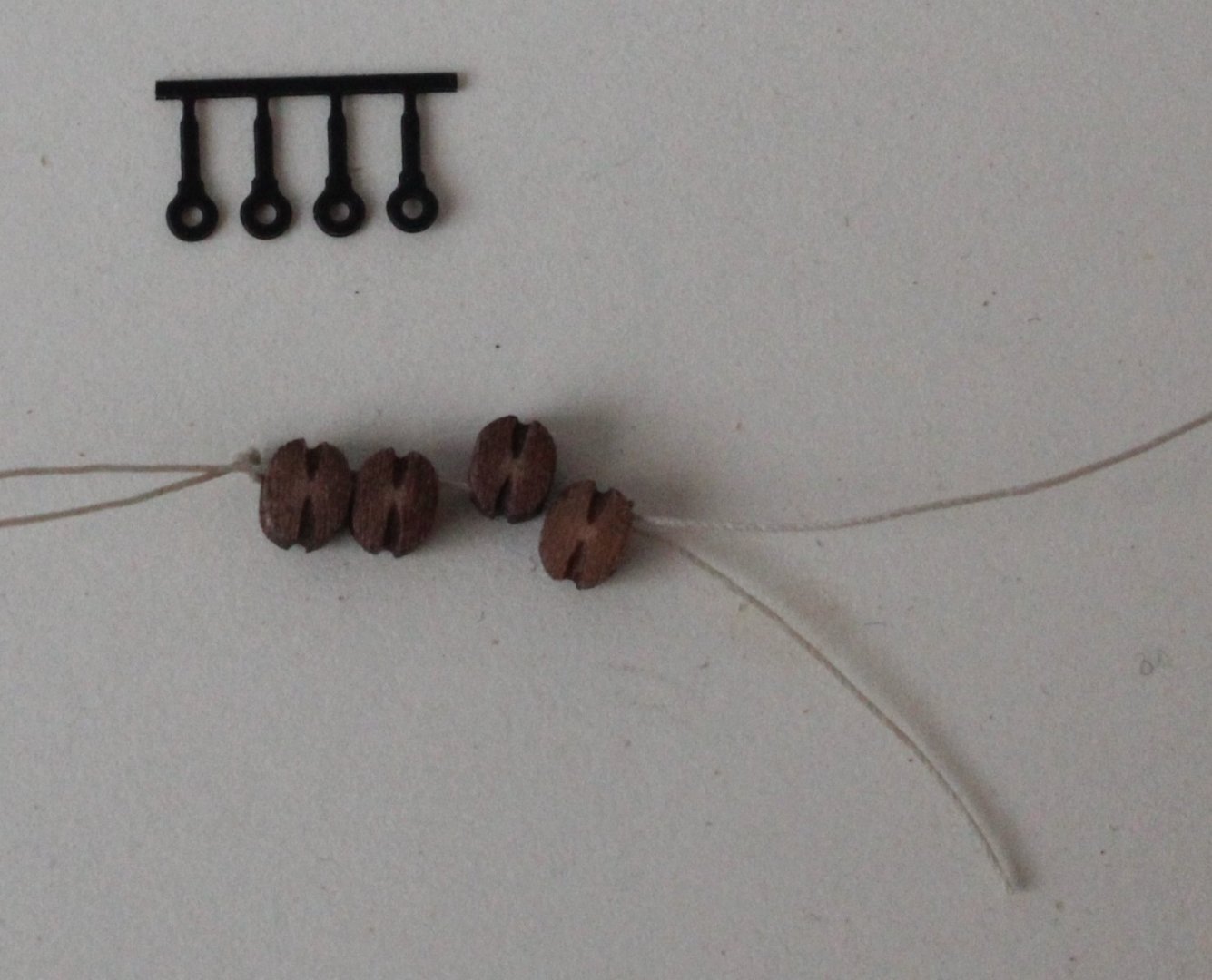
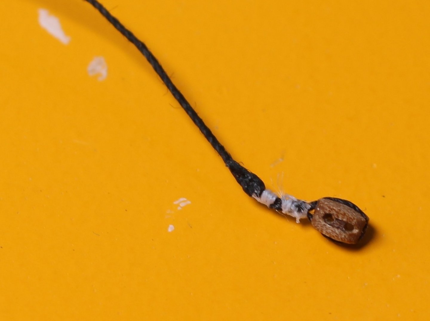
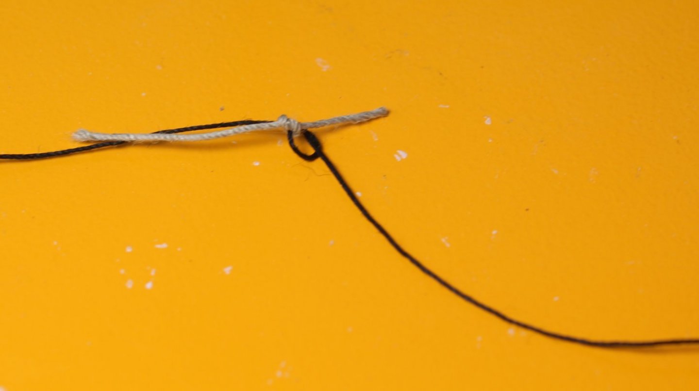
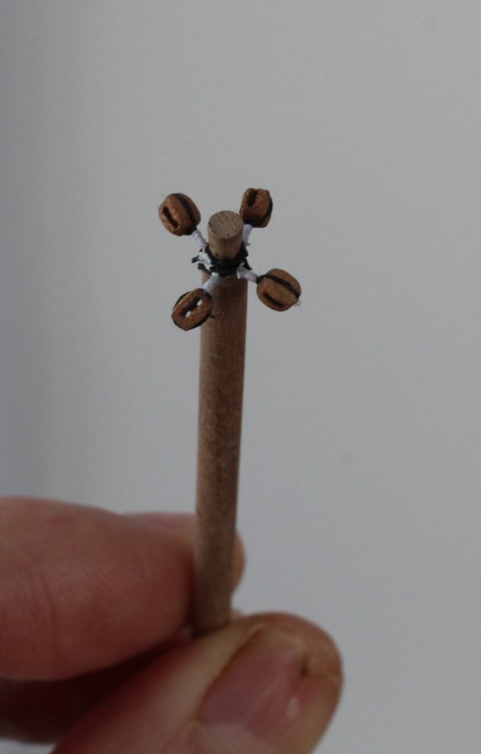
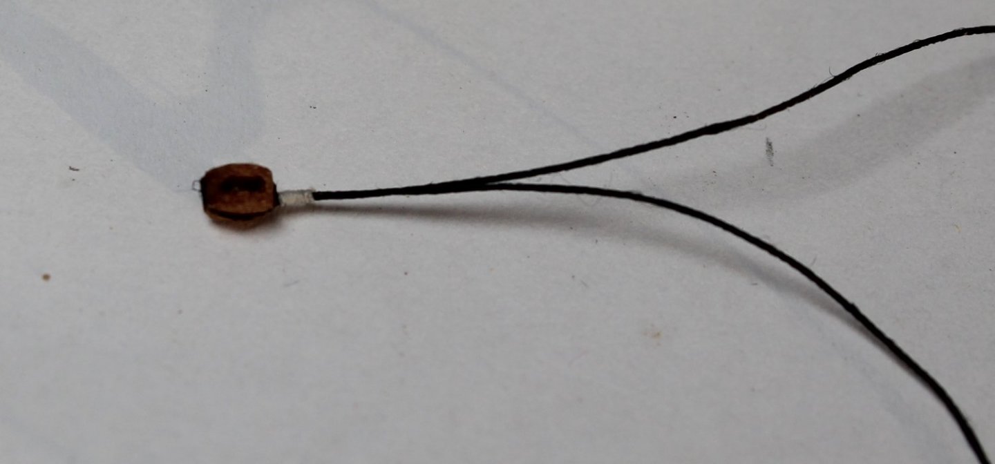
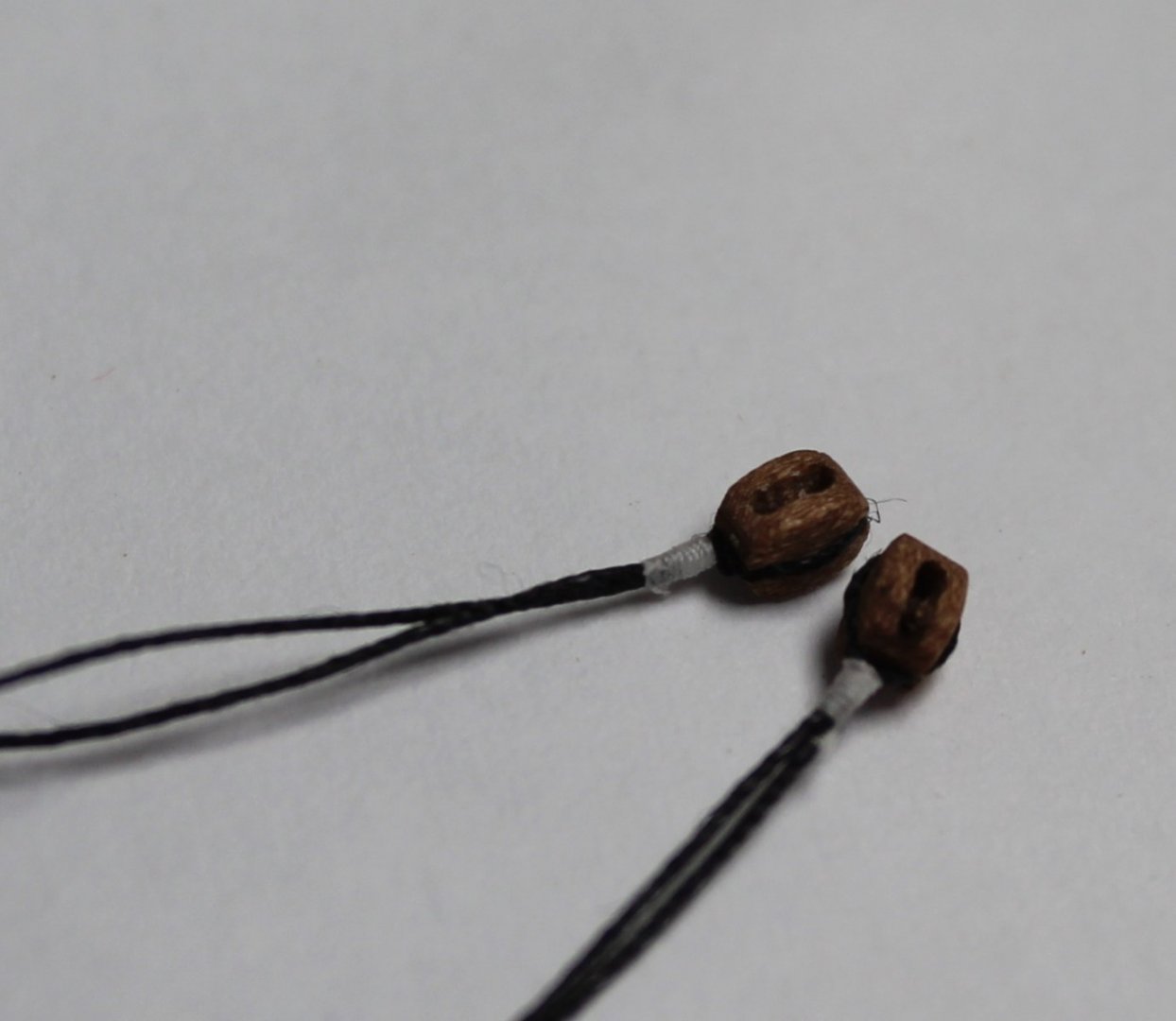
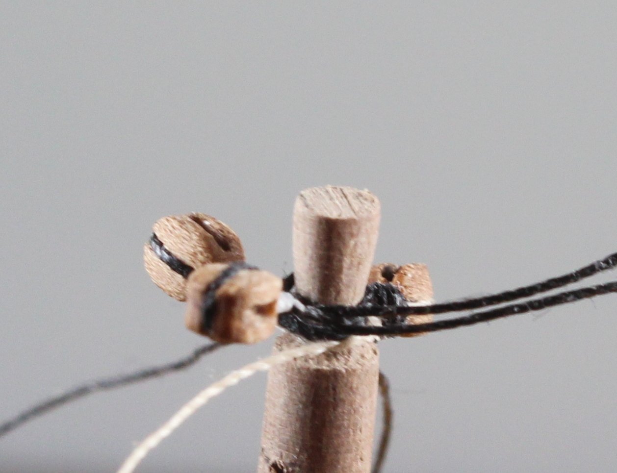
Bowsprit and Jibboom Work It has been slow going over the last couple of days working on the bowsprit and jibboom but I am getting there but it will probably be another few days before the work in complete once the two spritsail yards have been fabricated. Bowsprit As can be seen in the first three photos the various bit cleats, fairlead, jibboom support and whipping have been added. I then moved on to adding the various deadeyes and blocks to bowsprit and end cap. I used the method detailed in DELF build log for adding multiple deadeyes on one thread. In simplistic terms the deadeyes are added to the thread and given the nature of the whipping the deadeye positions can be adjusted. When adding the eyebolts to the end cap a length of thread was added to the bottom eyebolt in readiness for rigging to the spritsail yard, the manual suggested 400mm, but I've included 500mm. The end of the bowsprit was then painted black and the jibboom was then temporarily added for a couple of photos. Jibboom There are 4 blocks required to be added to the end of the jibboom and I have been puzzling for the best method. My first idea was to add a ring to the end each block, The four blocks could then be threaded on a length of thread and positioned as required when the blocks are to be rigged. In the end I decided to abandon this approach as I was finding it very difficult to make an acceptable looking block. My best effort is shown in the photo below which looks to clunky. I then decide it would be easier to simply add each block in turn, the photo below gives an indication of the method, but the block rigging needs to be much better, the whipping is to bulky and I need to swap the colours, so the whipping is white. I then cast my mind back and remembered how I use to rig the blocks on Alert and the Duchess which is copying a method shown and described brilliantly by DELF in one of his build logs posts. The block is held in the quad hands and a length of black thread is held in position ready for the whipping to be added. I also remembered it was better to use a fly tying thread for the whipping, using a series of half hitches (top and bottom). In the picture below the first 6 knots have been added. I ended up adding 10 knots, the completed block is shown below, which looks so much better. It did not take long to repeat the process to make another block The two completed blocks were then test fitted to the jibboom. The first rejected block is also shown the next two photos to get an idea of how the end of the jibboom will look. I should be able to complete the work on the jibboom in the morning. I will then move on to making the spritsail and top spritsail yards.


- 476 replies
-
- 8
-
-
- sphinx
- vanguard models
- (and 1 more)
-
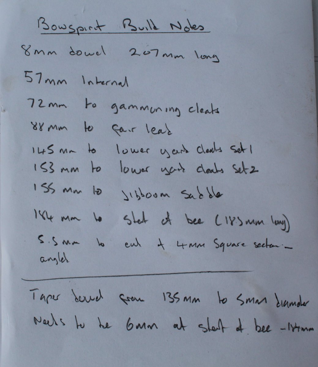
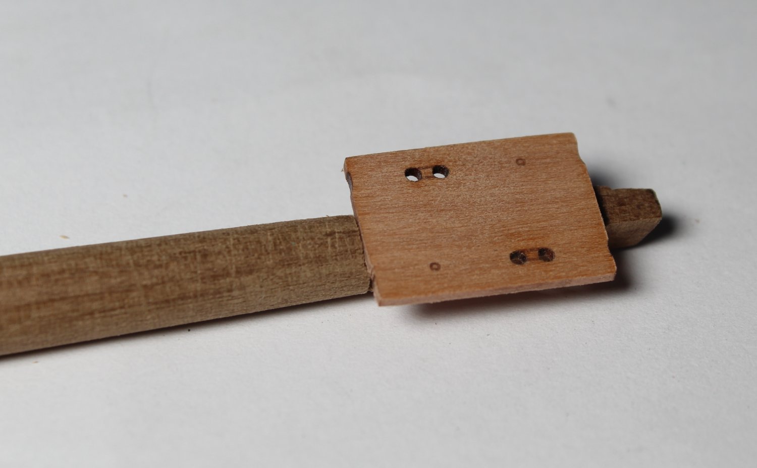
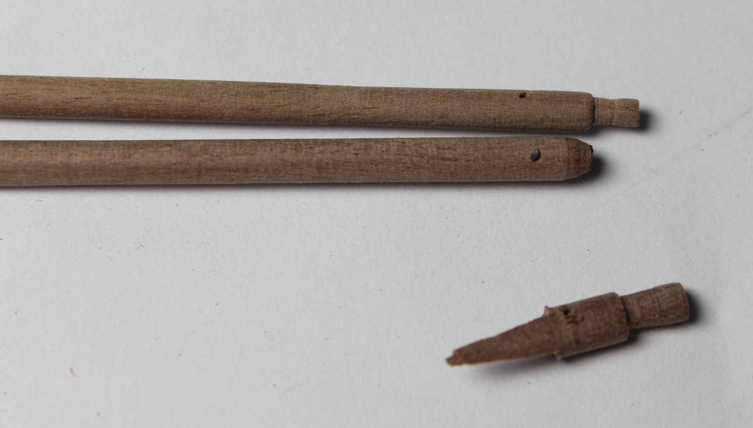
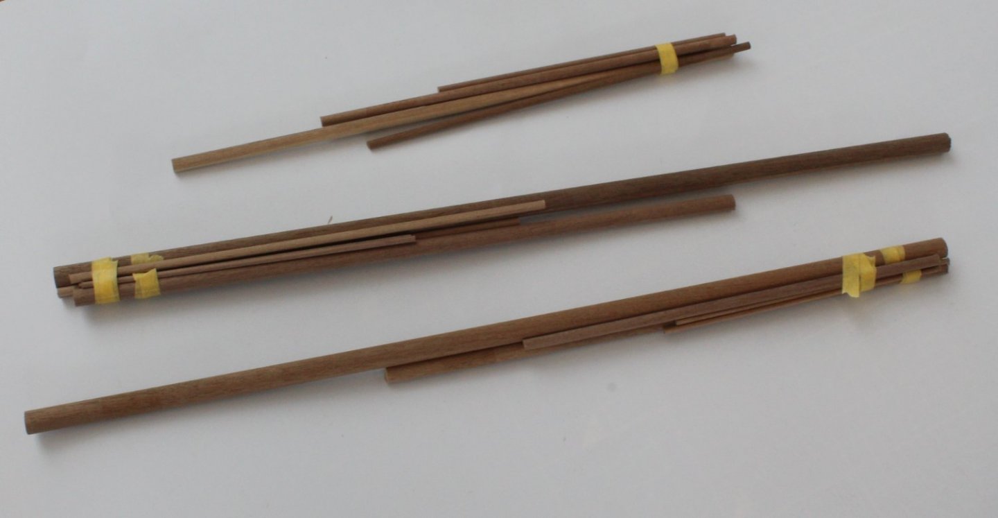
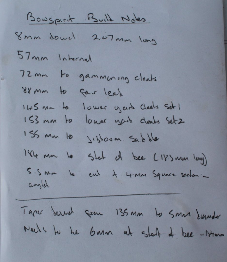
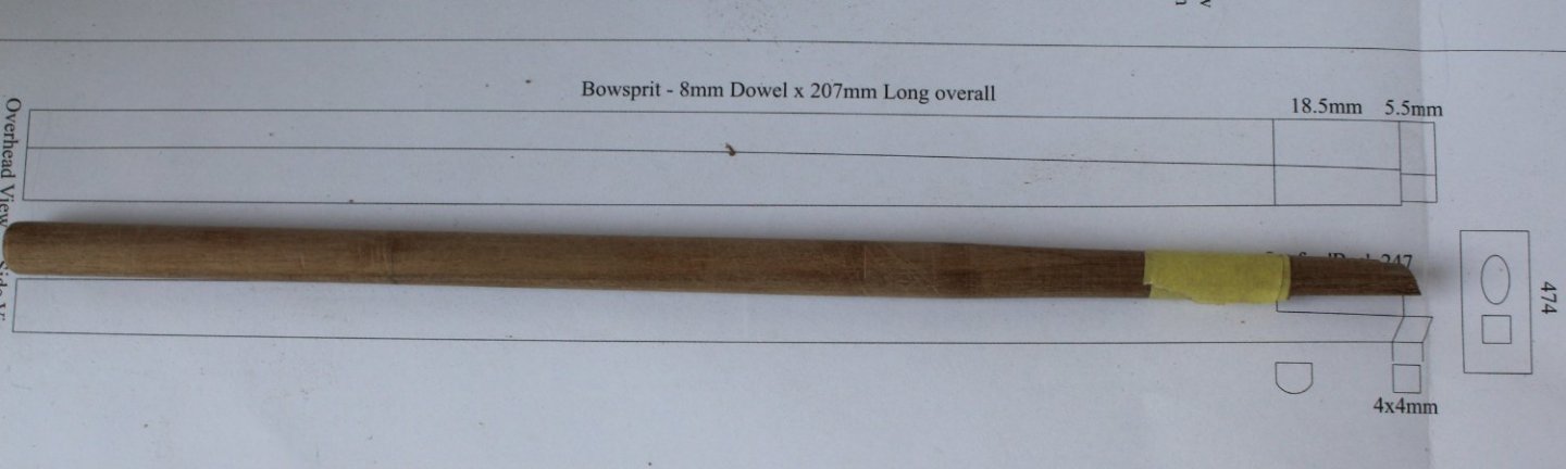
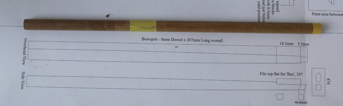
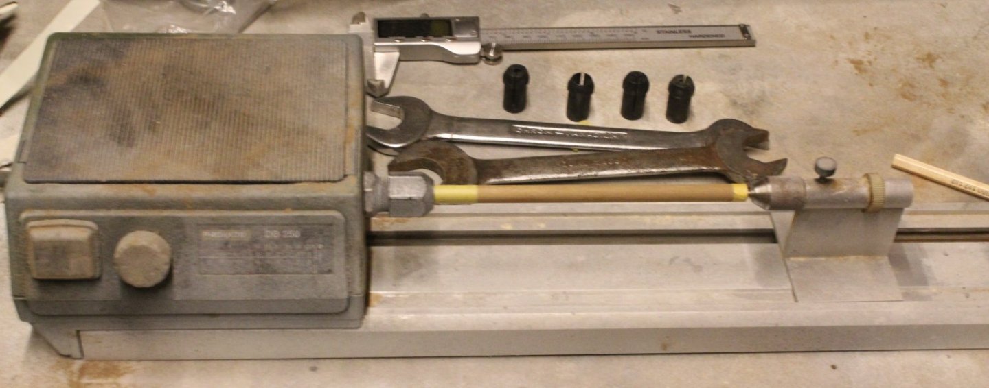
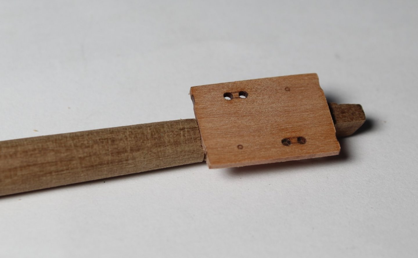
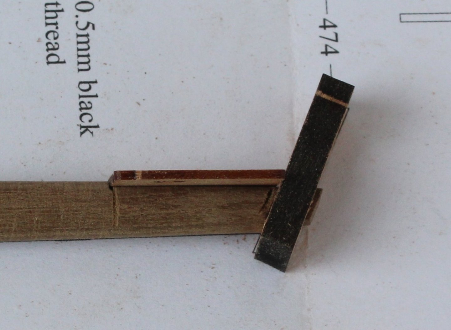
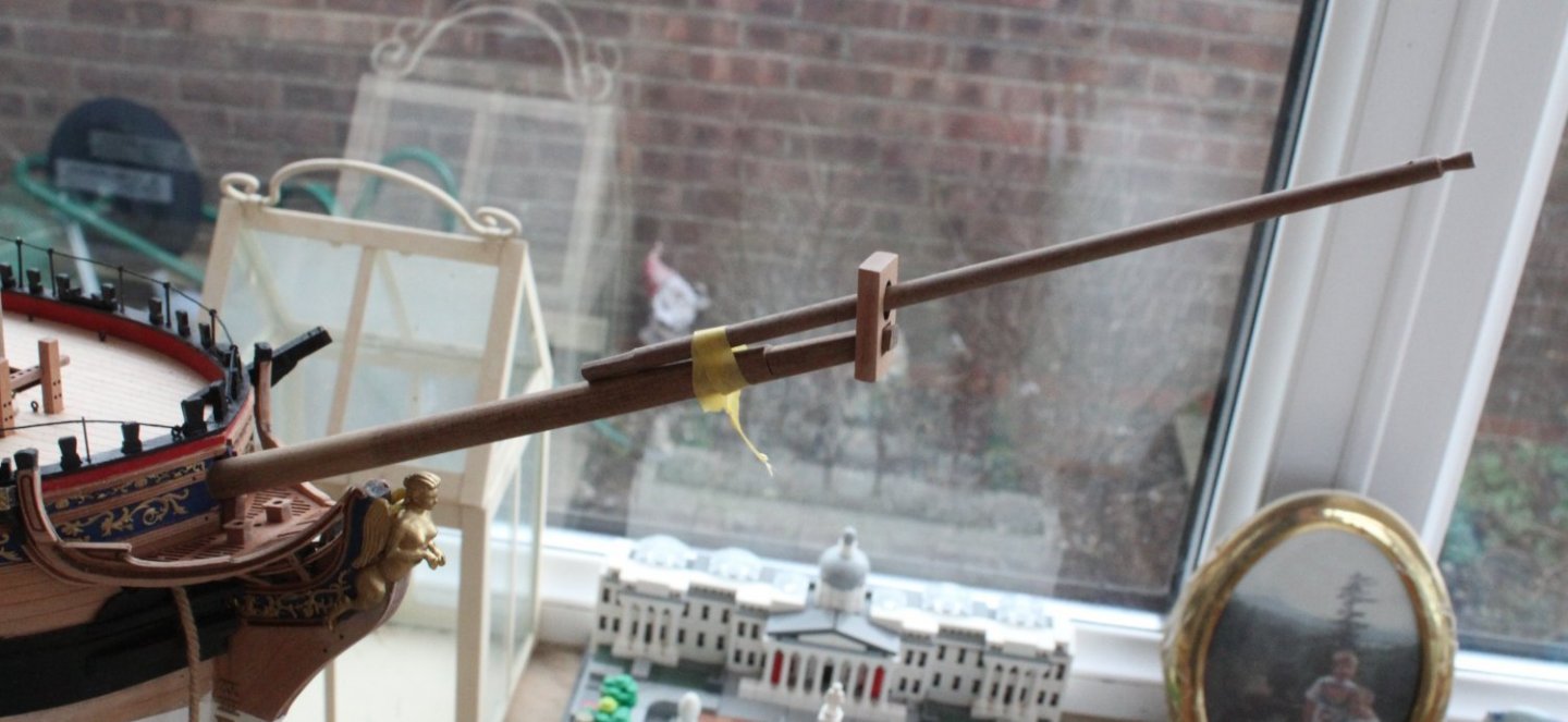
Bowsprit and Jibboom Fabrication The last two days have all been about making a series of school boy errors as I worked through the fabrication process for both the bowsprit and jibboom. Bowsprit I start this process by transferring the details on the plan sheet to a set of instructions, as seen in the photo below. Please note I did amend the final dimension of the start of taper of 135mm, after double checking my notes. Given the detailed plans and my notes what could possibly go wrong? For some unknown reason I decided it would be a good idea to trim the end and cut off the end squared bit required for the end cap. On to take two. I started by taping the start and end of the taper sections. I do like to allow a bit extra at the end. The dowel is then placed in my mini lathe ready for adding the taper. I use a course sandpaper for the bulk of the sanding and the reduce down to a 400 grit for the final smoothing. It does not take too long to get the required taper. I do stop and check the dimensions up and down the dowel several times during this process. Once the taper section is complete the dowel returns to my work bench where I add the flat required for the bee. To do this the dowel is clamped to the work bench. I make a saw cut where the edge of the bee will locate and the flat edge is created. I use a craft knife to create the flat edge and then finish off using a Florey sanding stick. The bee is checked several times during this process until I am happy with the end result, as shown below. I also remembered to leave the extra bit for the end cap. As can be seen in the photo below I started to make a saw cut on the side and will be filled prior to painting this section black. The end cap sits at exactly the right angle as shown on the plan sheet. The various bit are now ready to be glued to the bowsprit. The first item I will add are the gammoning cleats. I have add the tape and marked the positions of the cleats. Jibboom Looking at the plans this appeared to be a relatively easy piece to make. Boy was I wrong. It took me 4 attempts before I actually managed to make one. The first one I simply misread the plans and reduced the dowel down to 3mm which was far to slack for the end cap. Take two was going much better but the small end bit snapped off during the shaping process. Take 3 went really well, except I managed to snap the drill bit. I was unable to remove the broken end so I ended up cutting the end bit off, thankfully I had plenty of length left on the dowel as I had not added the octangle bit of the other end so it was not a total disaster. These are my failures. This is picture of the completed bowsprit and jibboom in position. In the final picture of this post I have trimmed the main and fore masts, ready for their shaping.


- 476 replies
-
- 10
-
-
- sphinx
- vanguard models
- (and 1 more)
-
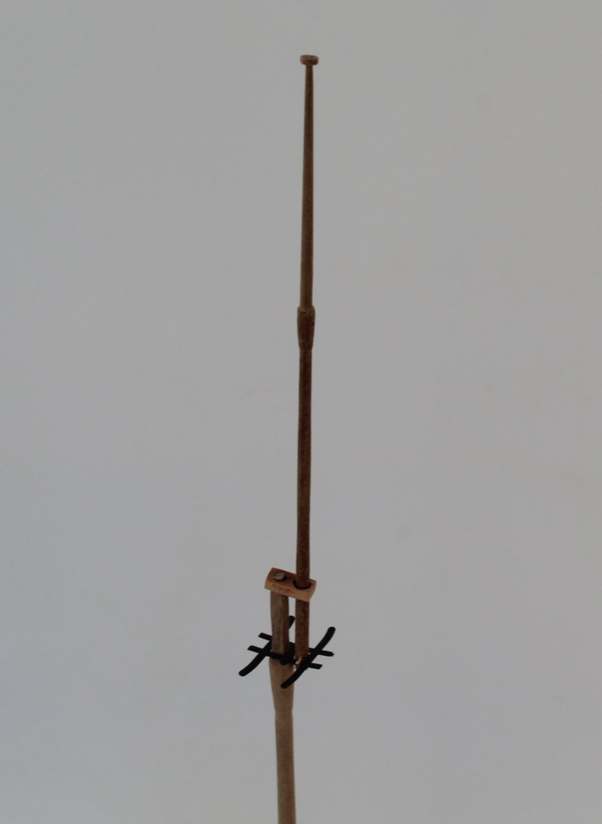
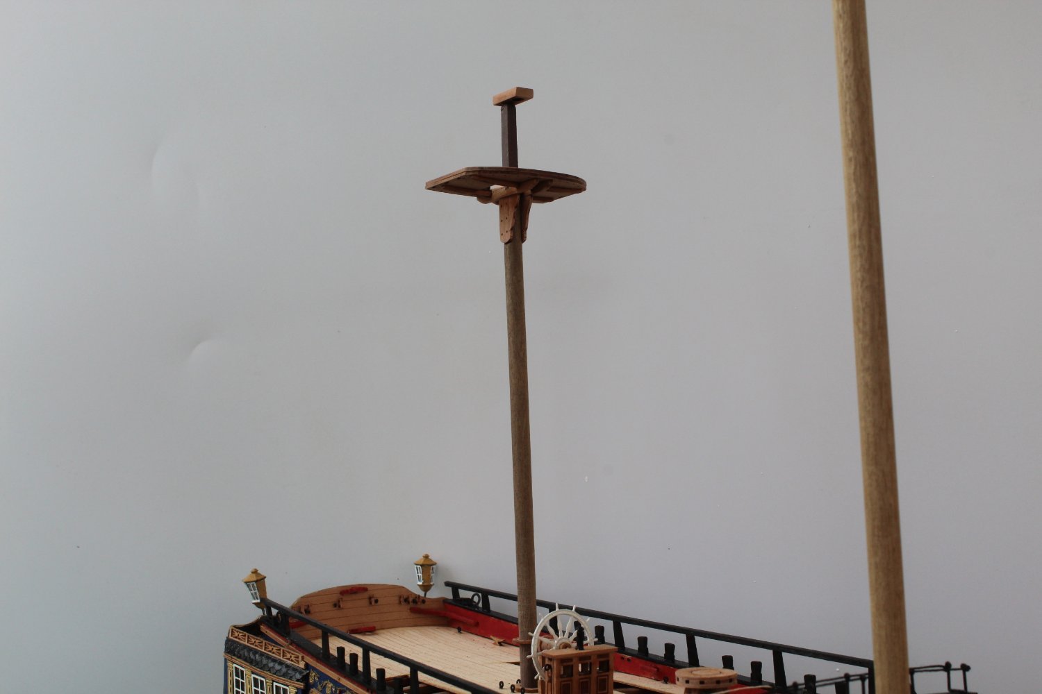
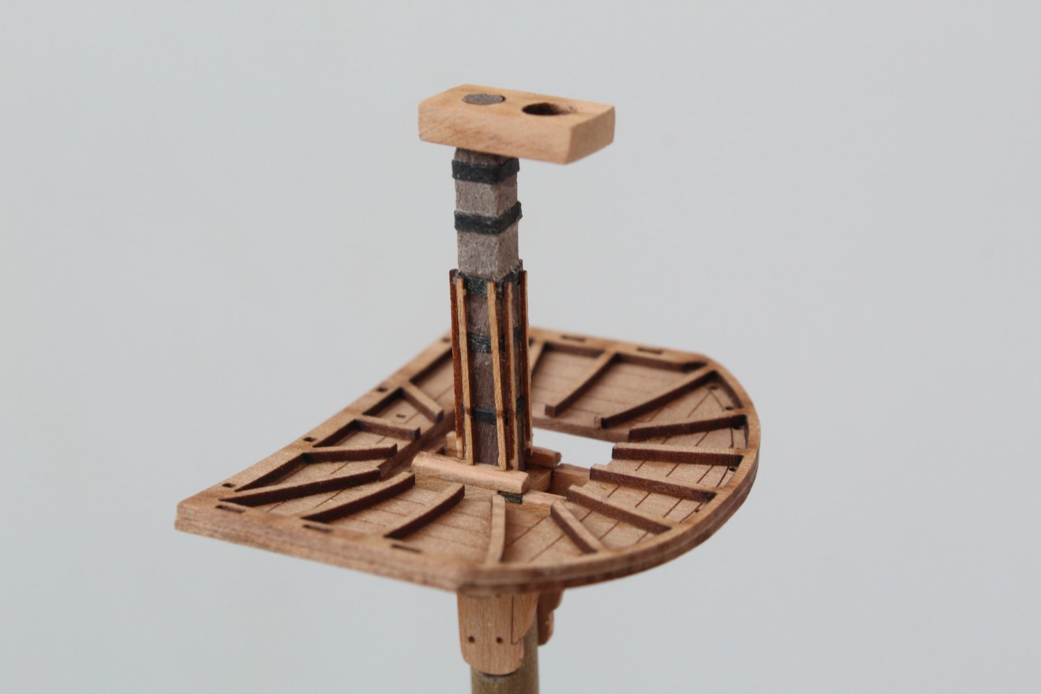
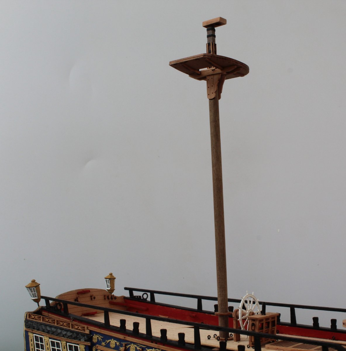
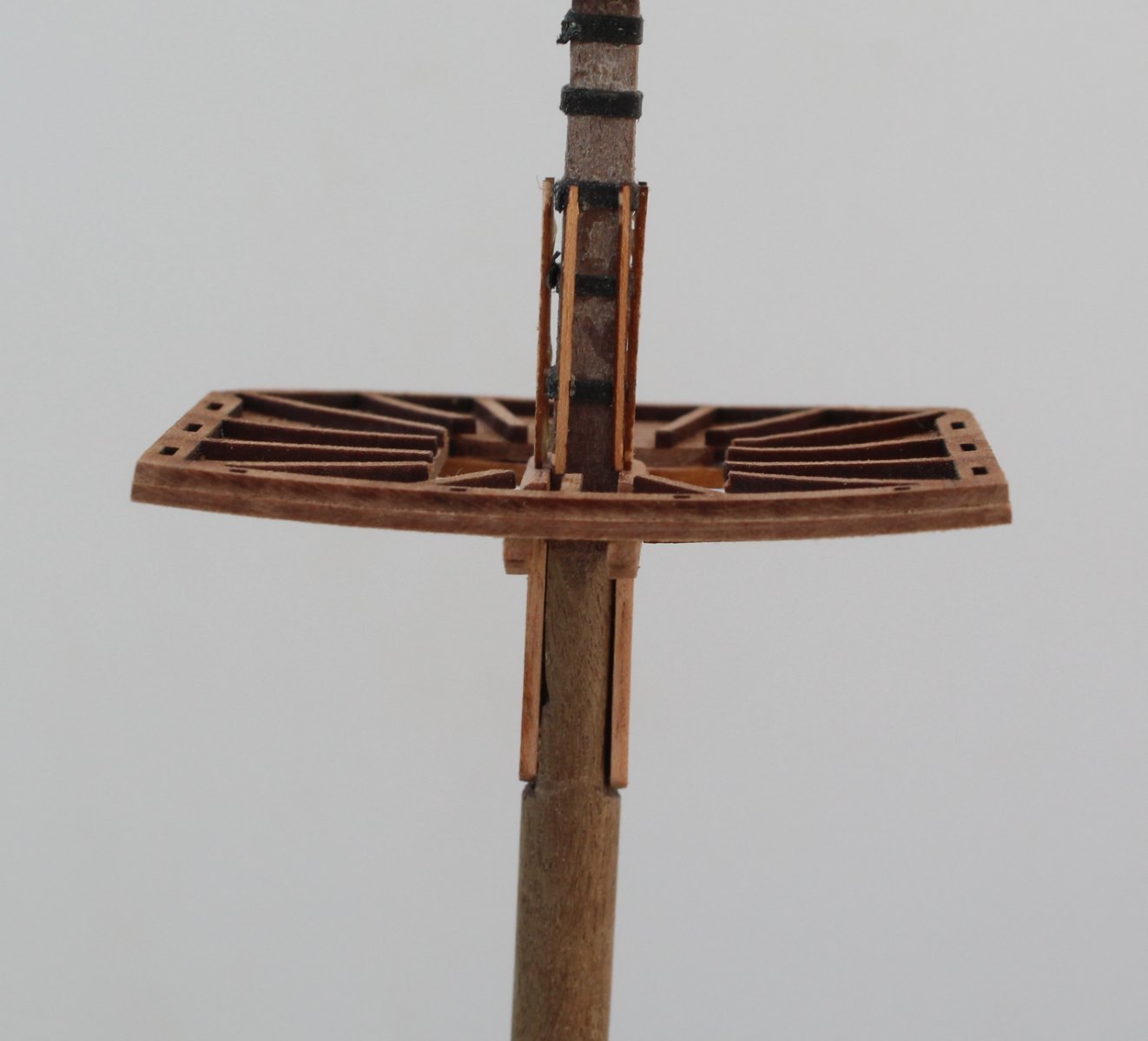
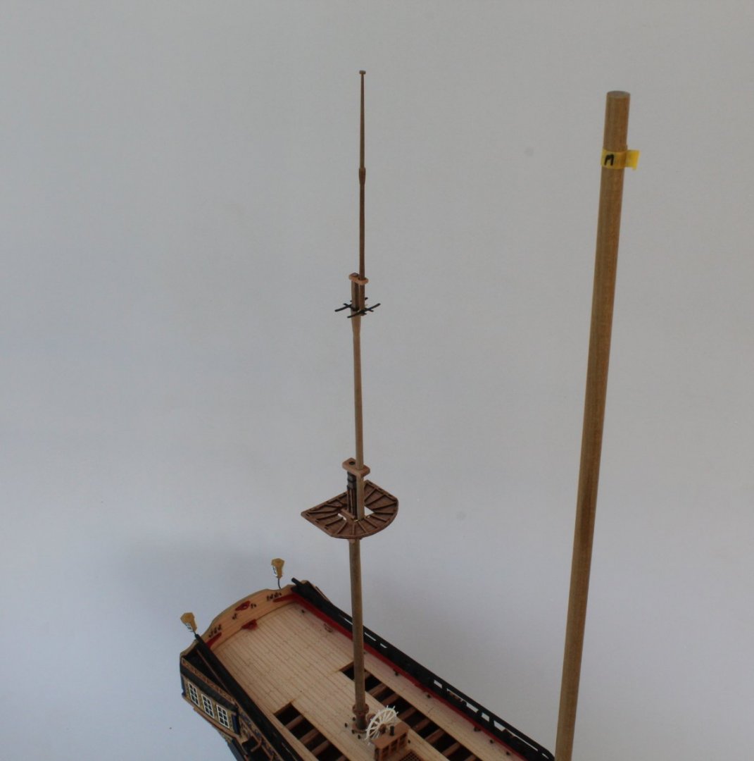
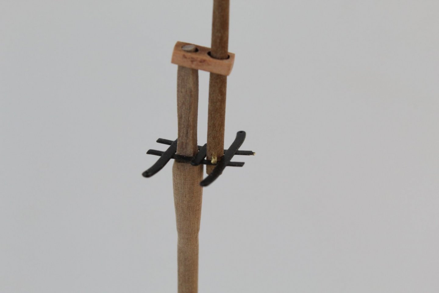
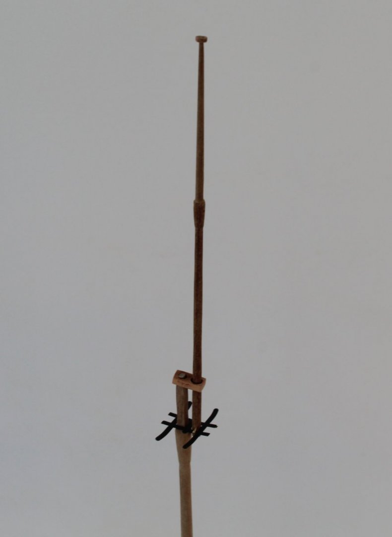
Mizzen, Mizzen Top and Mizzen Topgallant Masts I have managed to reduce the warping on the mizzen mast main platform. It is not completely flat but is much improved to an accepted level. I have now completed the basic shaping of the three masts required for the mizzen mast assembly. I did cover the shaping of the mizzen mast in my previous post, so this post will cover the topmast and topgallant mast shaping. All three masts have now been dry fitted with the various platforms and end caps. The photo below shows the mizzen and topmasts in position. There was quite a bit of work required to get the shaping right for the topmast which started life as a length of 5mm dowel, which I cut approx. 5mm longer than required. I started with using my mini lathe to shape the different round taper sections. Next I sanded the 3mm square top section. Once I was happy that end cap and topmast platform would fit as required I trimmed the topmast to the correct length. I then moved on to sanding the lower section to the required square shape, such that it would fit through the lower end cap and platform access holes. Next I sanded the square section with camphor edges which would allow the topmast to pass through the mizzen mast end cap hole. The final task was to drill a small hole ready for the FID, noting I am using a length of copper wire for the time being. The topgallant mast was manufactured from a length of 3mm dowel. The basic tapering was done using the mini lathe. I took great care as the dowel does become weakened when being reduced down from 3mm to taper section of 1.8mm down to 1mm. Once again I used a piece of copper wire for the FID, whilst test fitting. The end cap does sit square on topmast but it was a bit fiddly to get right for the when taking the photo shown below. This is a full length picture of the topgallant mast, showing the top cap in place. The final photo is shows the complete mast assembly in position, noting everything is only dry fitted at present. I will now shape the main and fore masts along with the bowsprit.
- 476 replies
-
- 9
-
-
- sphinx
- vanguard models
- (and 1 more)
-
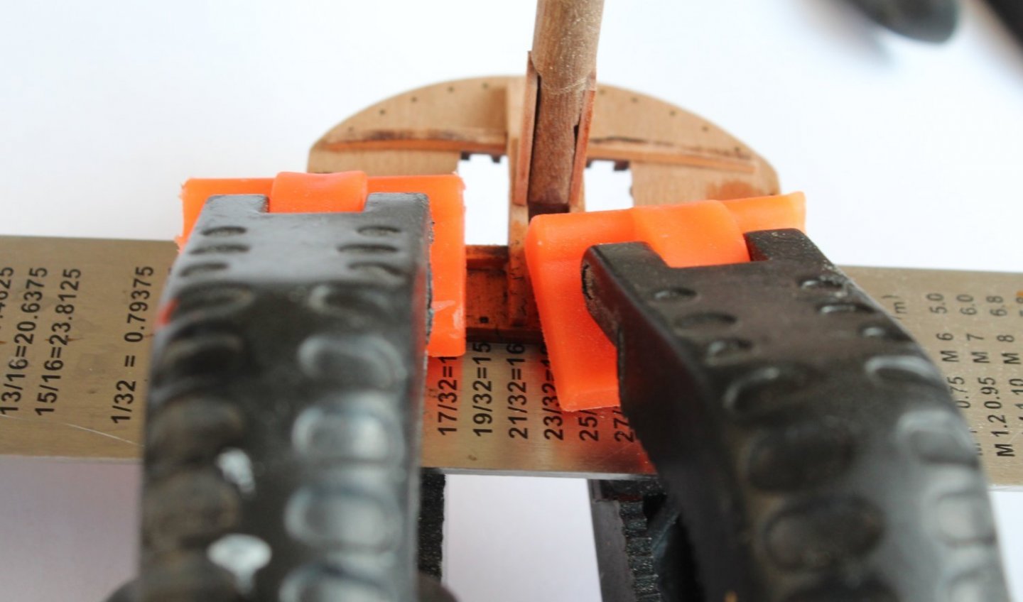
There are two bulkheads between the ship yard and gallery.The salmon was in poached in milk, covered with foil. The vegetables were oven fried. Very little steam. I have clamped in situ. A picture of the clamping in situ is now attached in a previous reply.
- 476 replies
-
- 3
-
-
- sphinx
- vanguard models
- (and 1 more)
-
Everything was clamped and dried flat before I moved on to the assembly. As per my other reply I think it is due to moisture engress when wiping away excess glue. I am going to try clamping whilst in situ to see if I can reduce or remove the warp. If not then it will be a fraught hour or two disassembling the mast to release the platform. I will leave this to dry overnight
- 476 replies
-
- 2
-
-
- sphinx
- vanguard models
- (and 1 more)
-
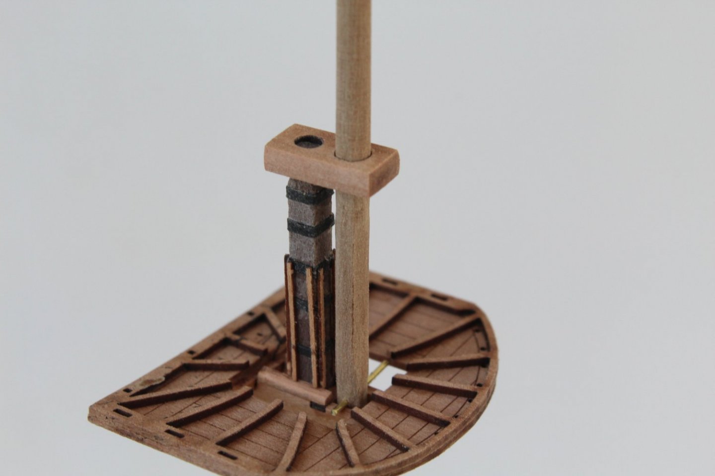
It is strange. When the two parts of the platform were glue together I clamped the entiire platfirm flat. This then allowed me time to build the crosstress and check the mast bibs. After a couple of hours I released the platform from the clamps and noted it was flat. I added the crosstree frame work and glued everything in place. Finally I added the banding and mast battens. I can only assume this was due to moisture engress when wiping away the excess glue, which resulted in the warping whilst I took an hour away from the shipyard to cook and eat lunch (poached salmon fillet with red and yellow peppers, red onions, cherry tomatos, mushrooms, cucumber and french fries.
- 476 replies
-
- 2
-
-
- sphinx
- vanguard models
- (and 1 more)
-
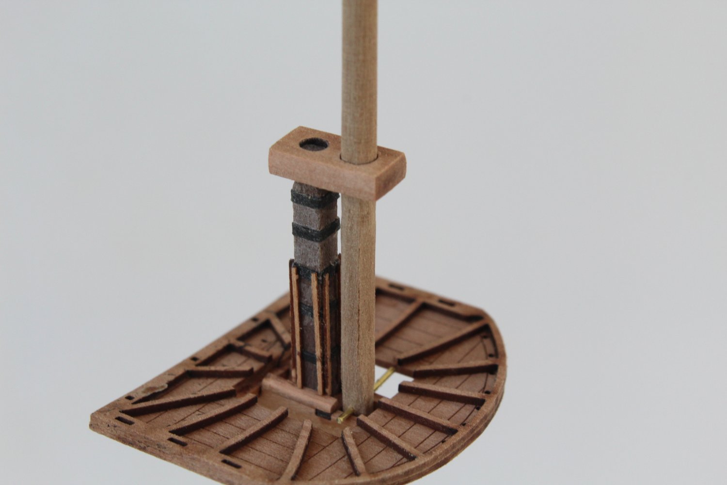
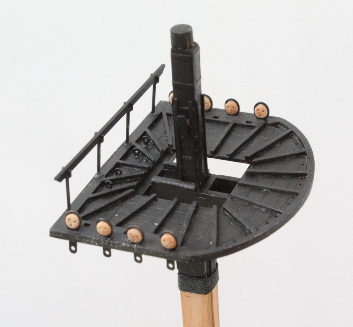
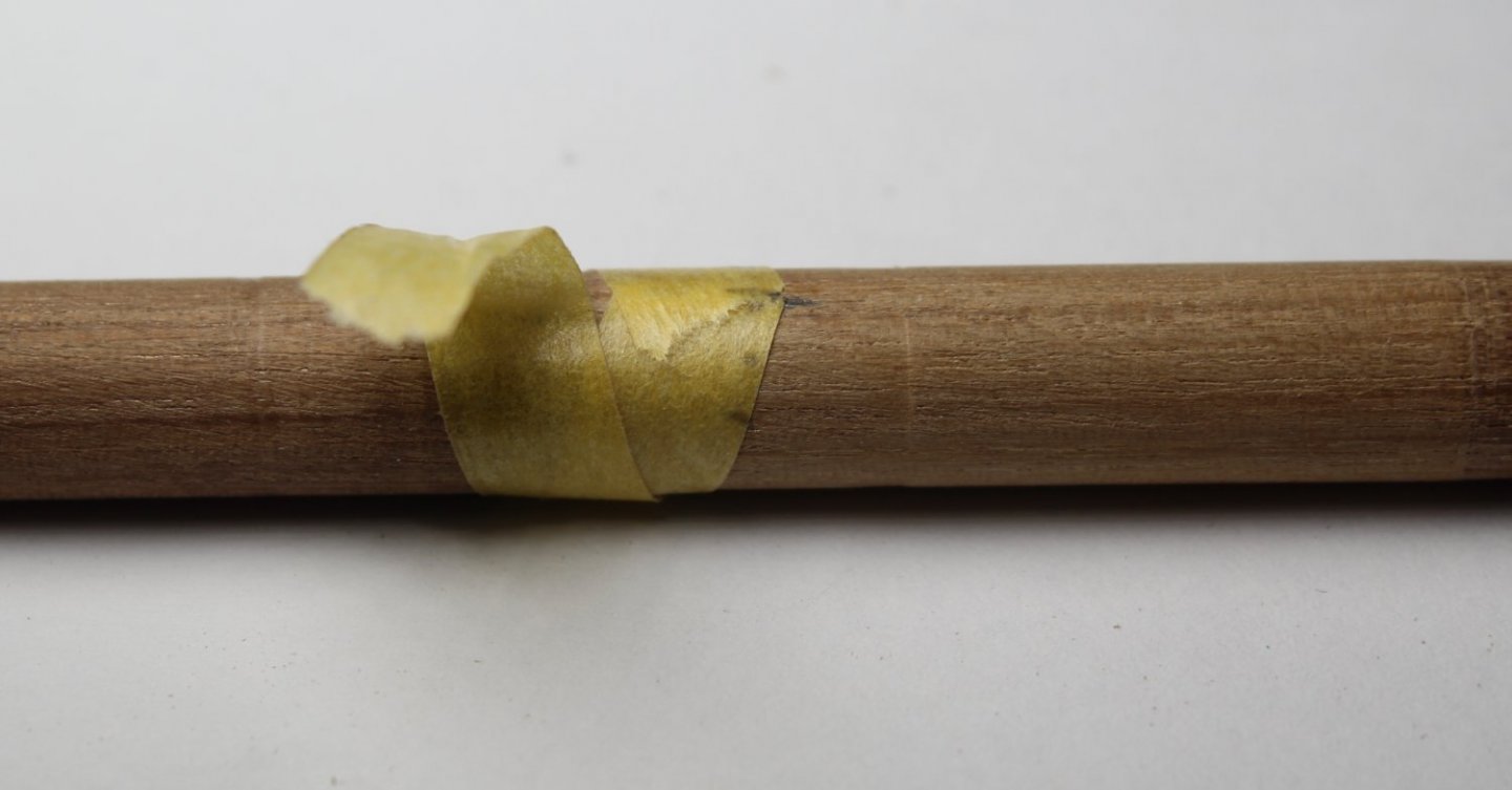
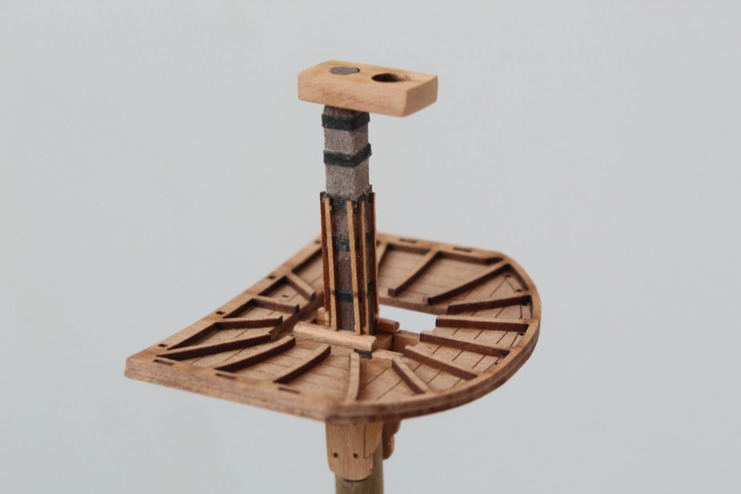
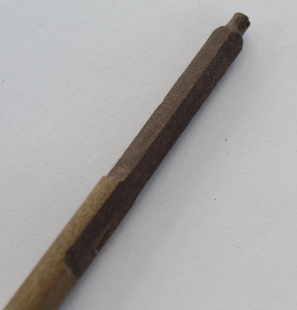
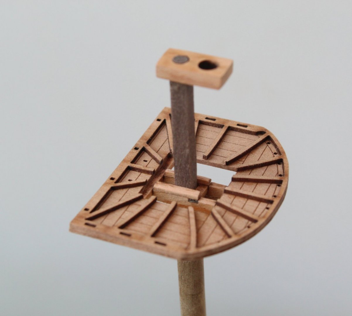
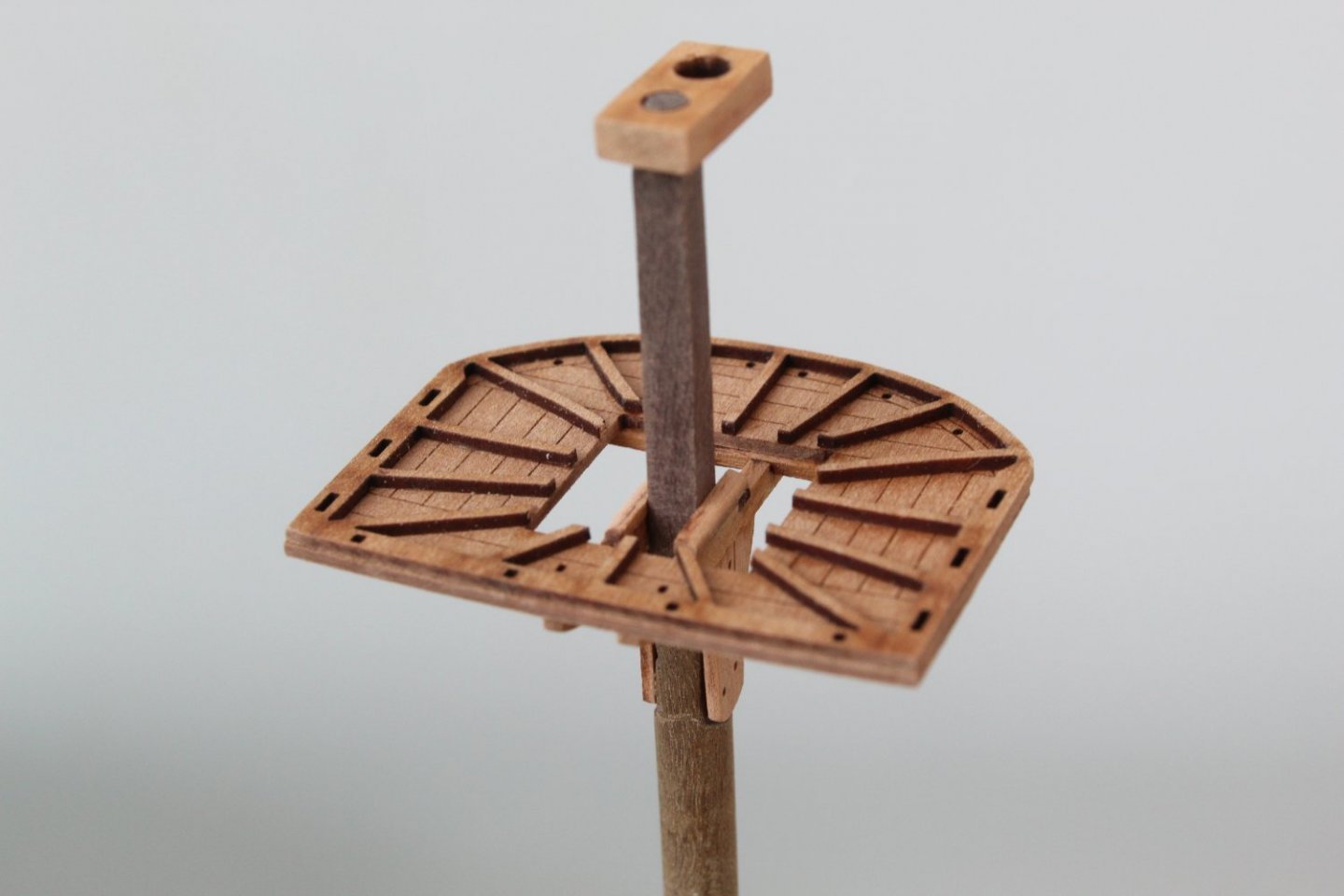
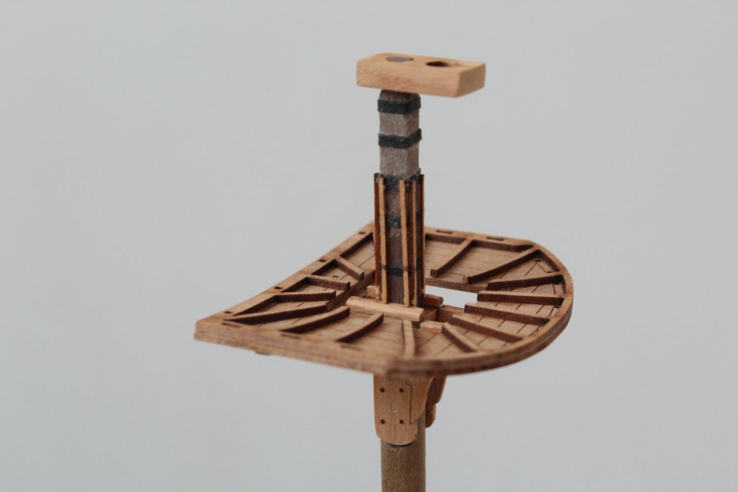
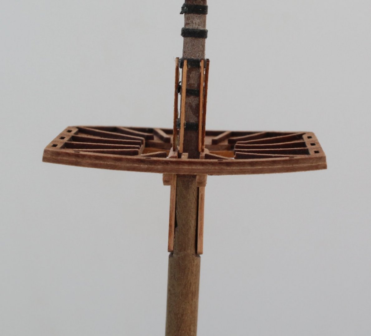
Mizzen Mast The mizzen mast is to be fabricated from a length of 6mm dowel. I cut a length of 6mm dowel that was approx. 5mm longer than required. This allows me to cut to the required length once the end cap has been trial fitted after then end of the dowel has been reduced to 3mm. I applied some tape to the lower edge where the bottom of the mast bibs would be located and some tape to the upper edge of the 4mm squared off section. With the dowel clamped to my workbench I used a Florey sanding stick to create a flat edge between the taped section. I then rotated the dowel through 180 degrees and created another flat edge. I kept repeating the sanding and rotating process until I had achieved an even width of 4mm. The lower tape was then discarded and a new piece of tape added to the position where the bottom of mizzen mast platform would sit. I simply repeated the same sanding and rotating process until I had an even 4mm square section. The dowel was the taken to my Proxxen mini lathe where the end of the 6mm diameter dowel was reduced down to approx 3mm. It was simply as case of checking to see when the end cap would fit over the reduced dowel diameter section. The end result of the mizzen mast fabrication process The platform section was then assembled. I shaped the two bolsters once they had been glued to the crosstrees, prior to fitting to the platform. The crosstree frame was then glued to the platform. The mizzen mast was checked and was a perfect fit. After checking the alignment of the two mast bibs with the platform they were glued in place along with the platform. The plaform is nice and flat. It was clamped flat to my bench whilst the glue had time to cure. The mizzen mast belaying pin ring was also test fitted, as can be seen in the photo below, slightly hidden by the ships wheel. The platform is still nice and flat. The banding strips and mizzen mast battens were added. I glued each banding strip in place as shown in step 860 of the build manual. Once the strips were set in place it was a simple job to add a touch of glue to the banding strips and to wrap each one around the mast in turn. The excess banding material was then trimmed away. Adding the mast battens was a fiddley task but I took my time to complete the task. With everything looking good I was very happy with a good mornings work it was time for a lunch break. Upon my return to the shipyard after lunch I noticed the platform had become warped along the back edge as can be seen in the next photo. I am now in a bit of a quandary. I could try removing the platform from the mizzen mast to see if I can correct the warp by wetting and clamping the platform flat. The mast banding and battens can be removed without to much effort and I can always make new battens if any become damaged. I am concerned if I can remove the platform without damaging it. I know I can brush some water to help release the platform from the Titebond glue. I think I will have to take the bull by the horns and try to sort out the warp, so fingers crossed I can do this😧 The warp can be seen on the photo below also It does not look as bad when viewed from a distance but it is still noticable.


- 476 replies
-
- 5
-
-
- sphinx
- vanguard models
- (and 1 more)
-
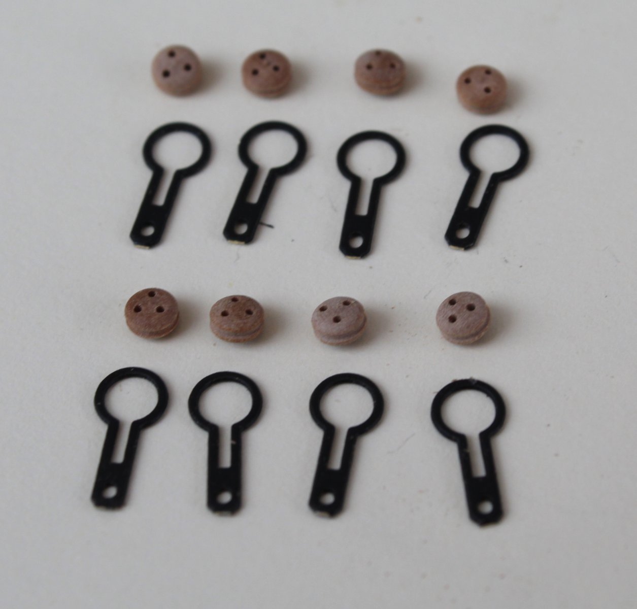
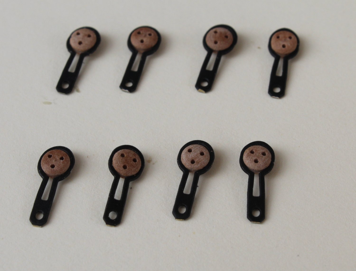
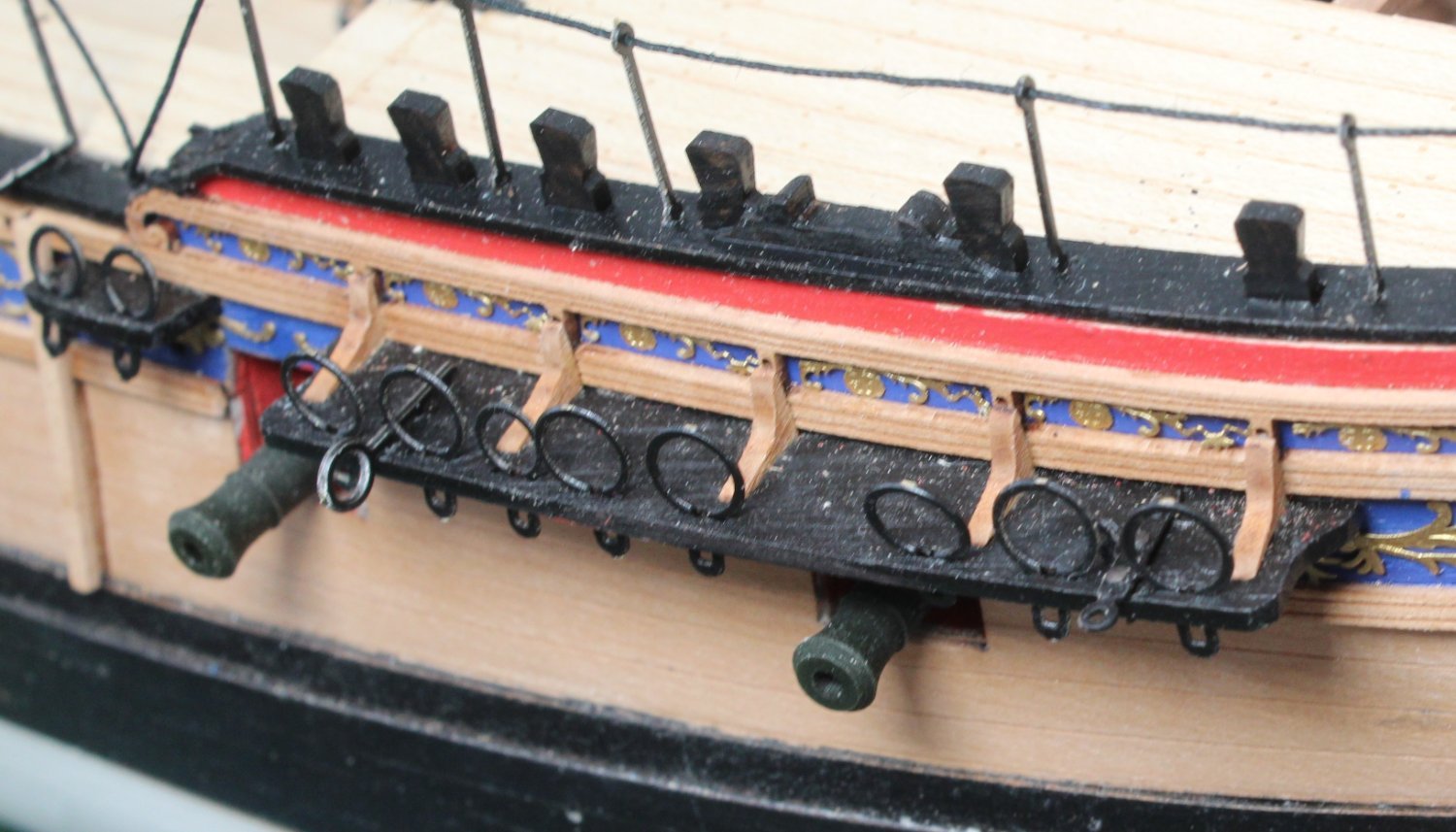
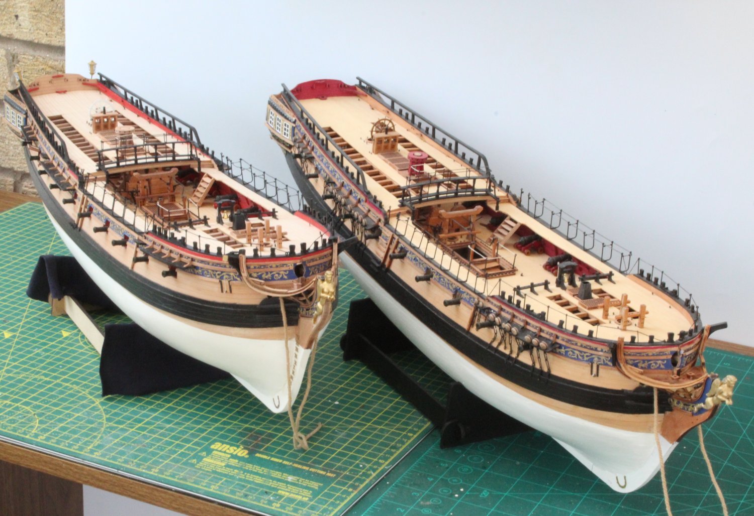
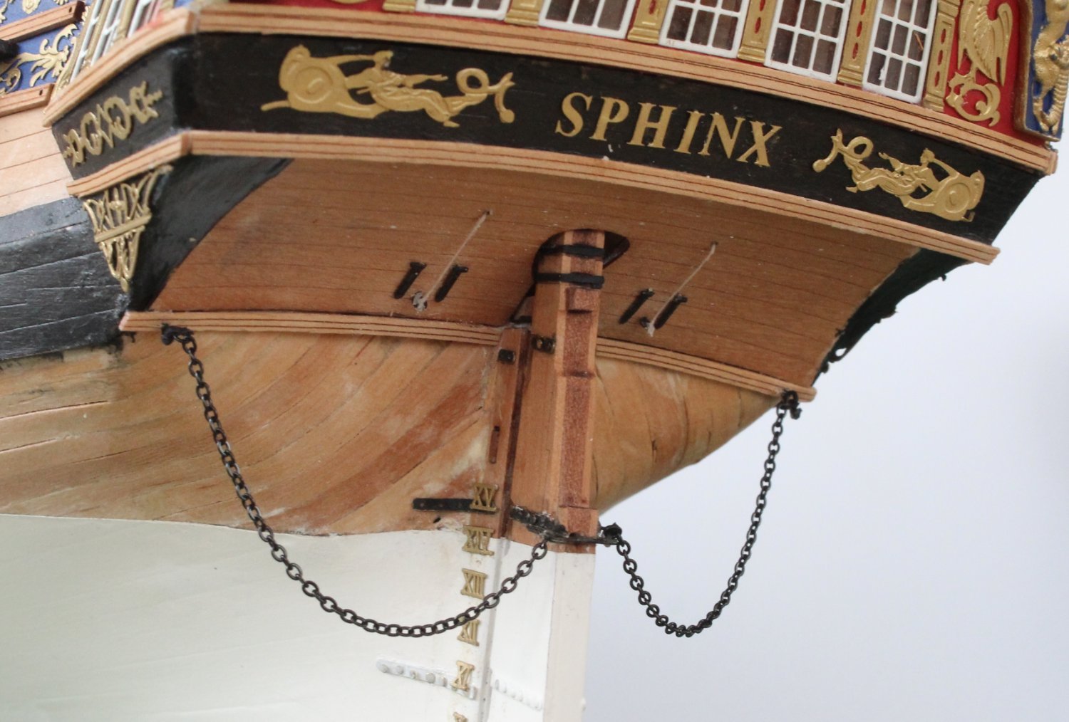
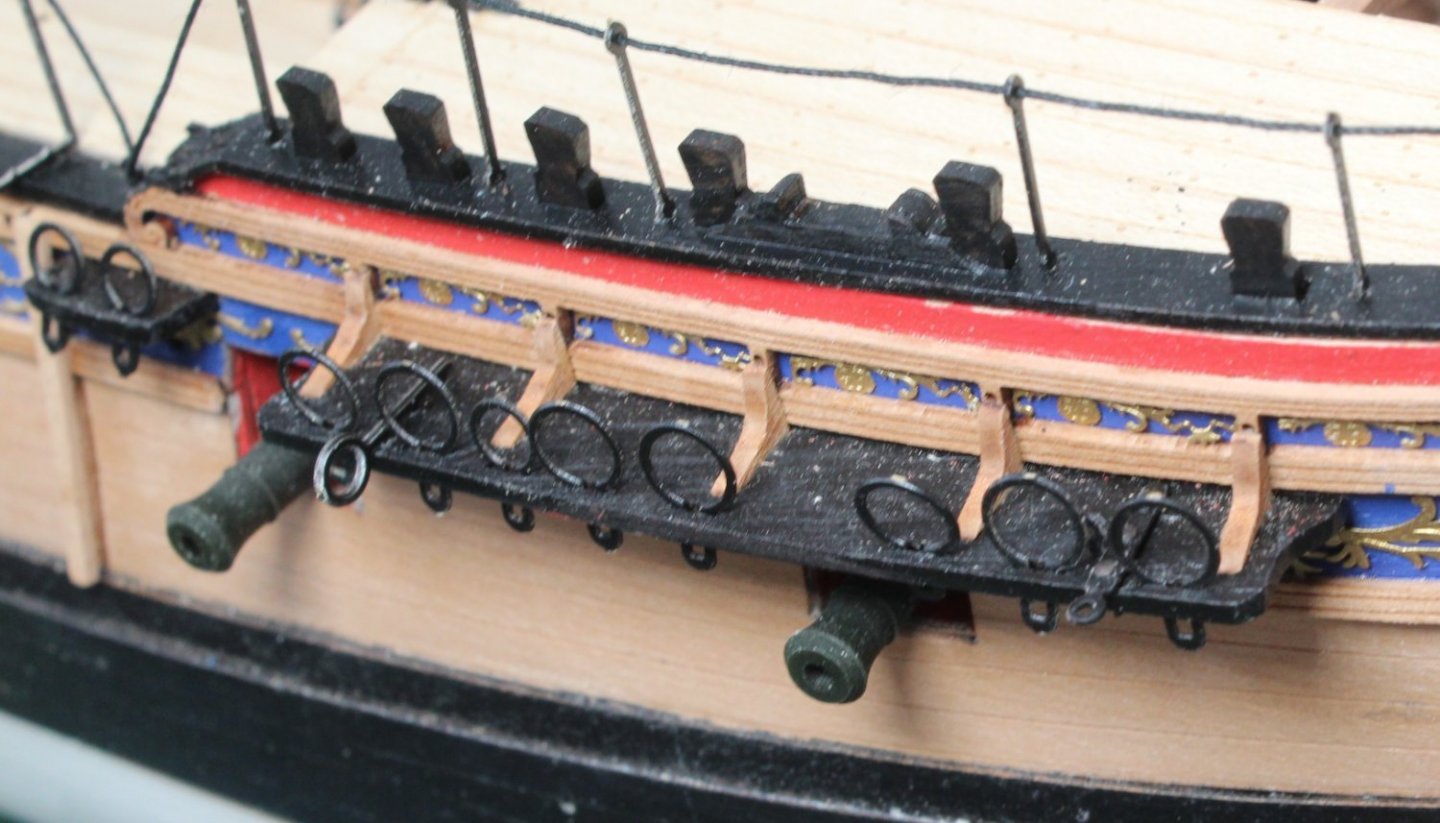
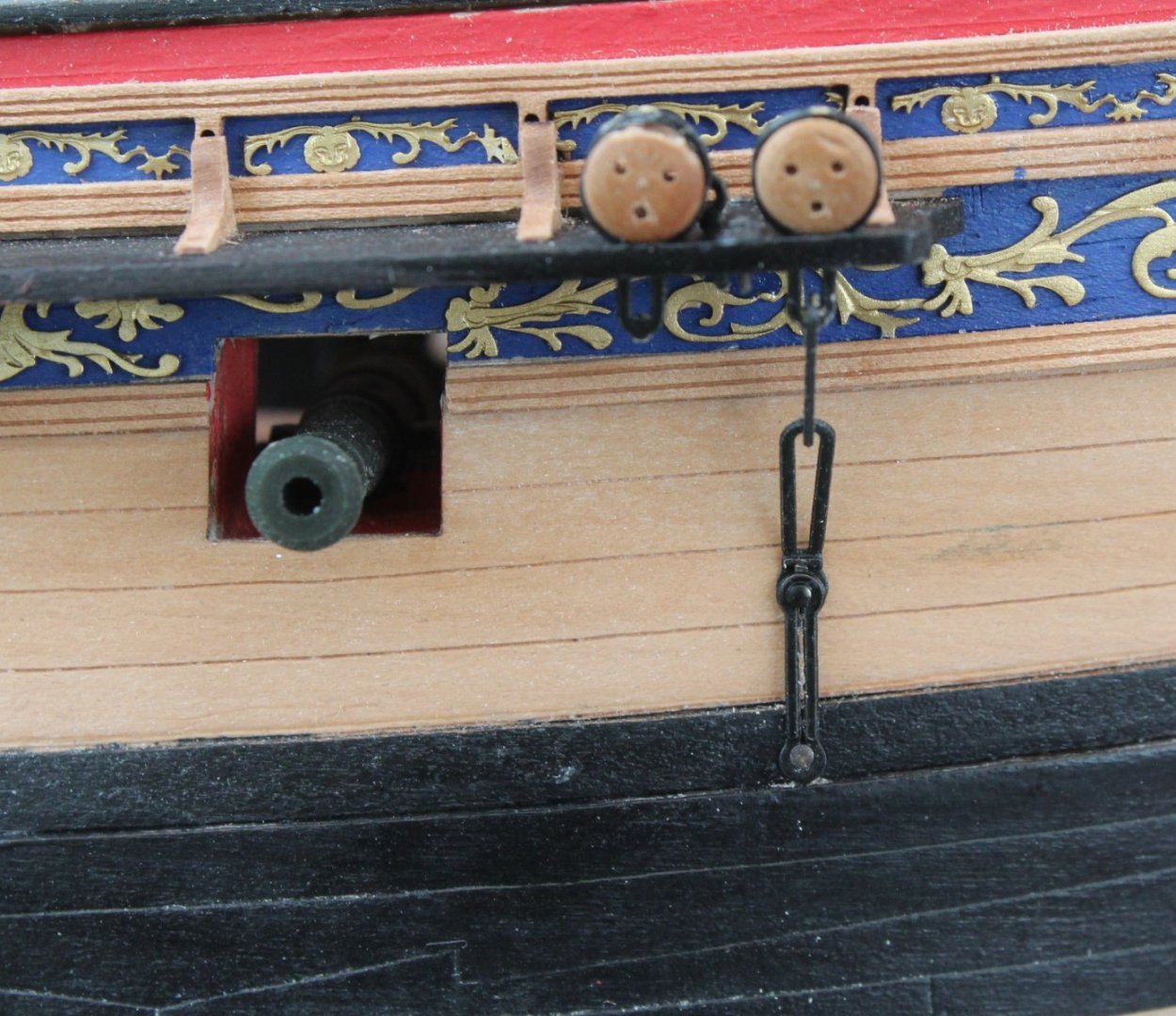
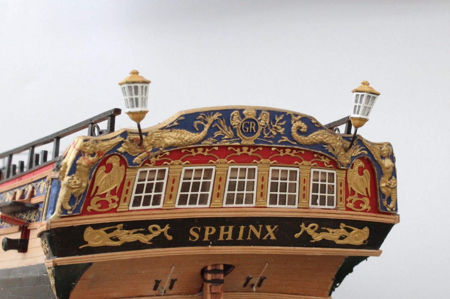
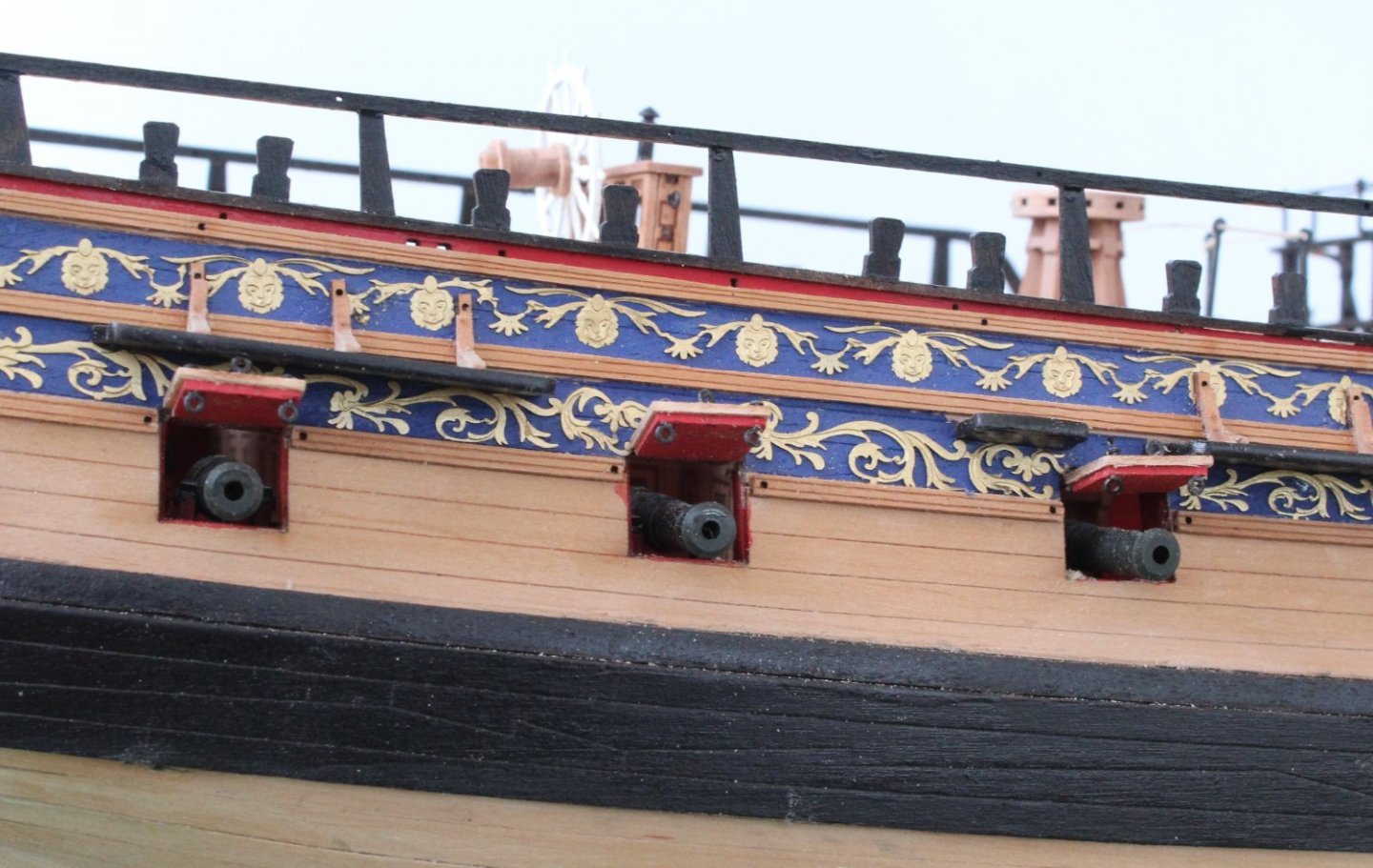
Hull and Deck Work Complete I have completed the finishing touches to the hull and deck. The two lanterns have now been added to the stern fascia. It is not my best work but they look OK. Next the rudder chains were attached. I may have left the chains a tad long but they are both the same size and look symmetrical so I am happy. The 6 gun post lids have bee assembled and affixed to the hull. I took the decision not to add the thread from the central eyebolt to the hole in the hull. I might change my mind but I think once all the rigging is in place the missing threads will not be noticeable. The last task undertook was to add the figurehead. The resin figure head was washed in acetone and then soapy water before I painted her gold. It took a bit of effort to fit as initially the part would not fit over the stem post. After a bit of sanding the figurehead could be fitted. To finish of this post I decided to place my V1 and V2 builds side by side. The one of the right is V1 build and will destined to a visit to the local tip once the V2 build is complete. I have started work on the mizzen mast and have built the mizzen mast platform assembly.


- 476 replies
-
- 9
-
-

-
- sphinx
- vanguard models
- (and 1 more)
-
Thanks, I'm looking forward to starting work on the masts and yards.
- 476 replies
-
- 2
-
-
- sphinx
- vanguard models
- (and 1 more)