Glenn-UK
-
Posts
3,175 -
Joined
-
Last visited
Content Type
Profiles
Forums
Gallery
Events
Everything posted by Glenn-UK
-
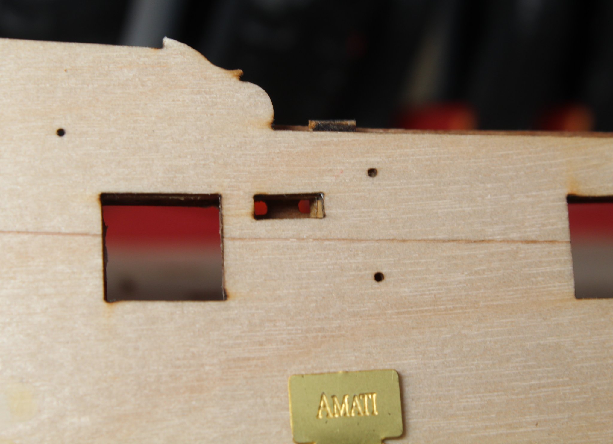
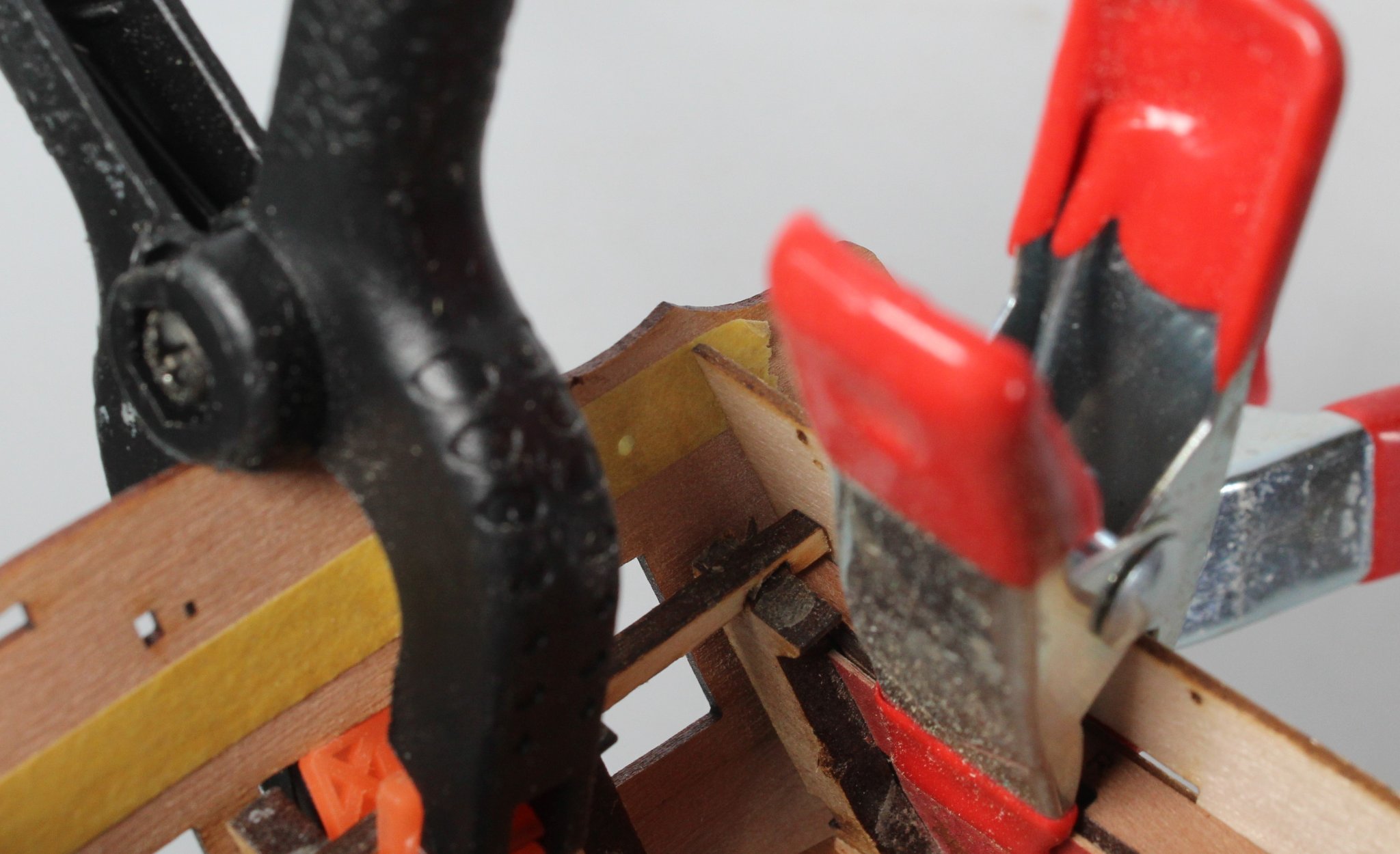
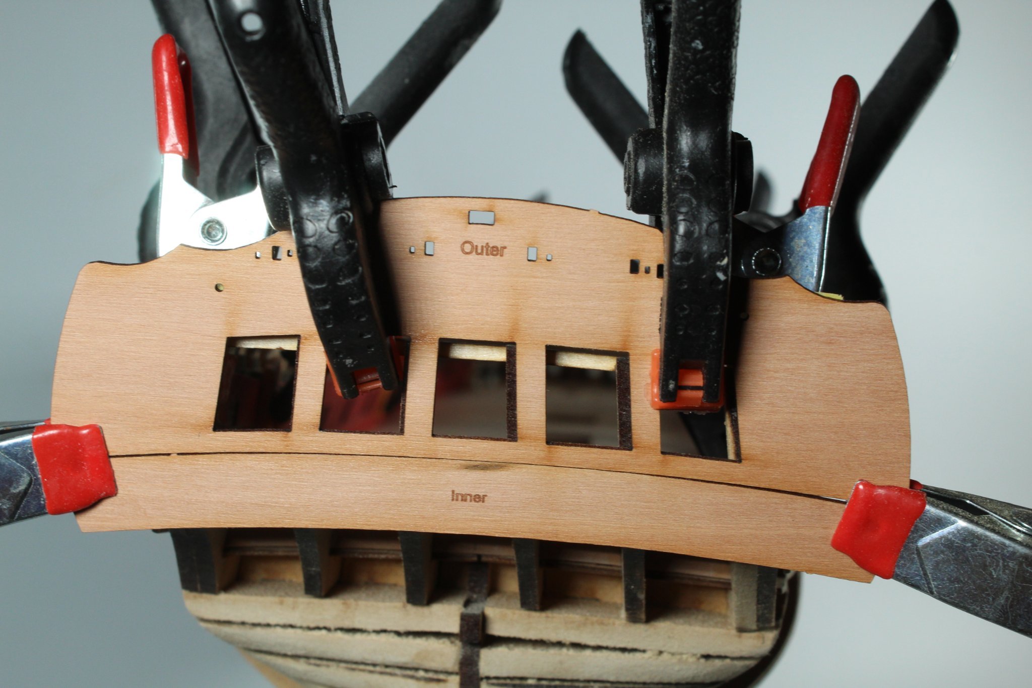
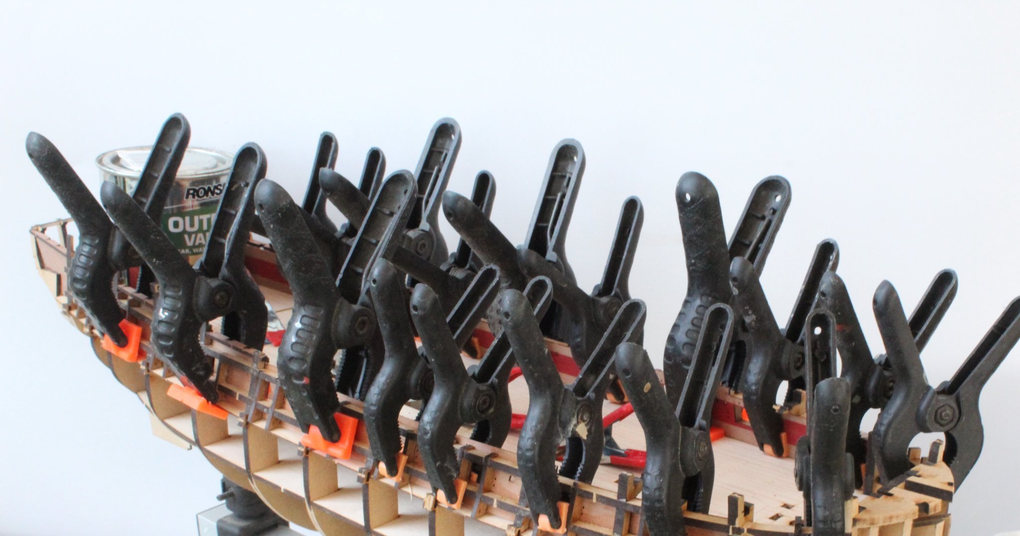
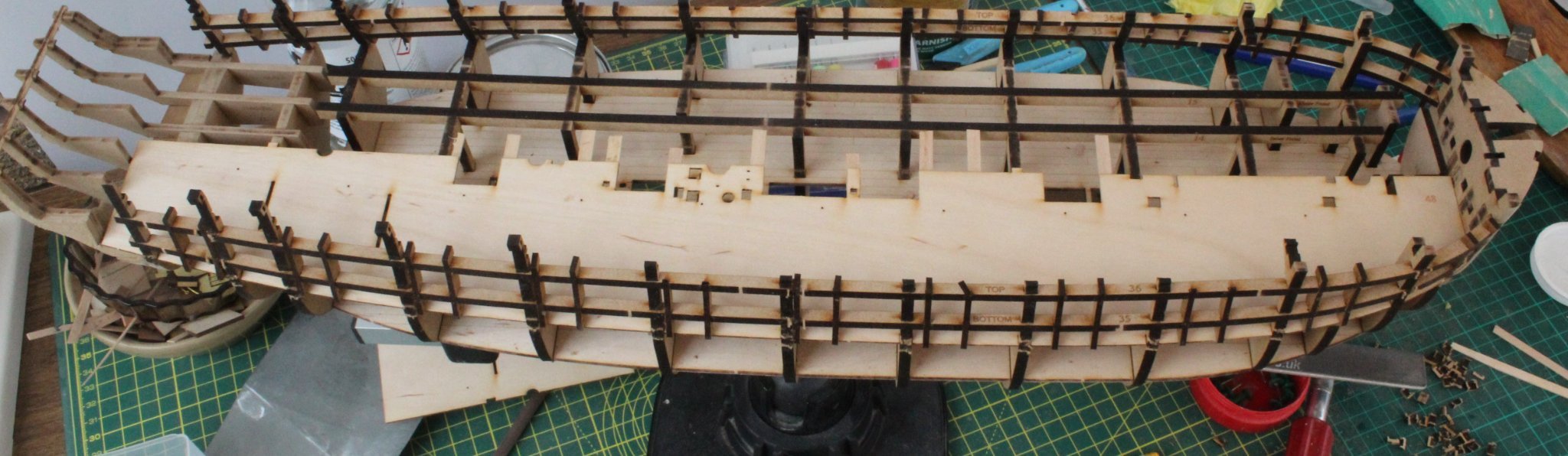
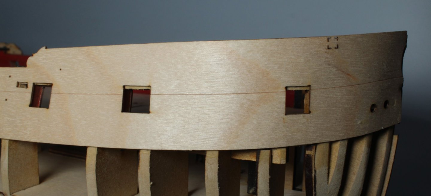
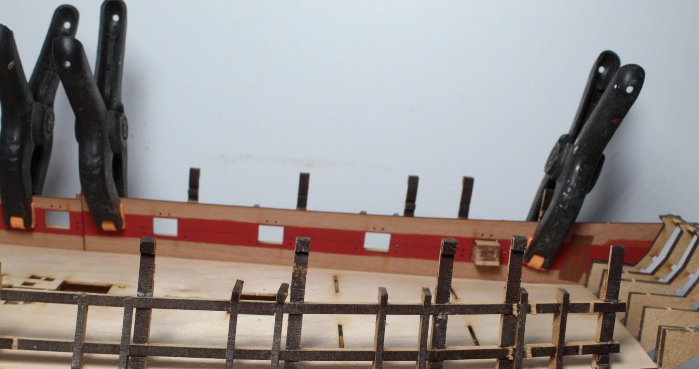
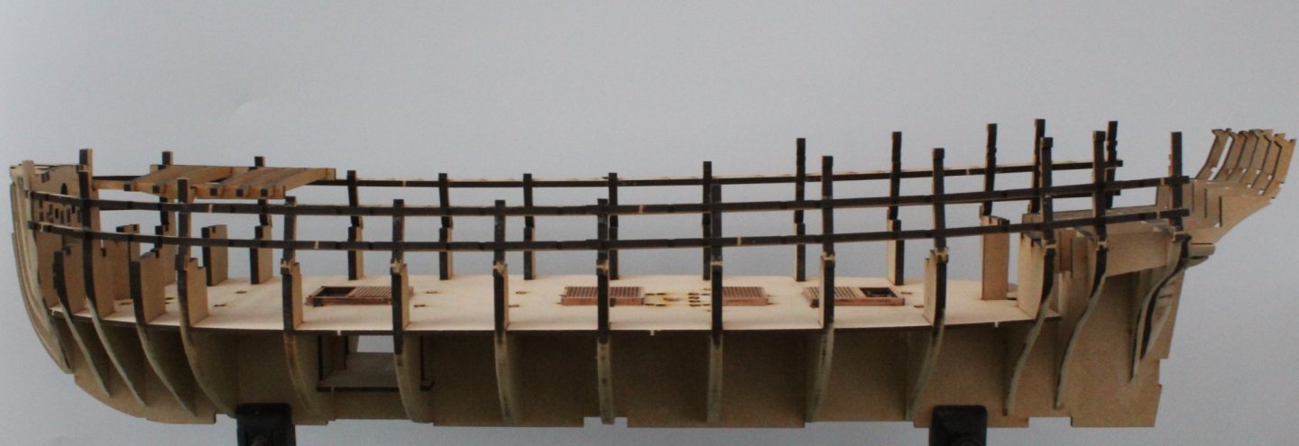
 Attempt two at fitting the upper side patterns has gone much better. @DelF I have not used all my clamps as I had 20 unused clamps, but I still used quite a few. The bow looks much better, the left hand pattern is perhaps a tad high, but I'm happy with how it looks. The MDF part (sitting proud) can be trimmed. It looks worse on the photo. The left hand pattern is correctly aligned with all the gun ports this time around. Gun port alignment on the left hand side.
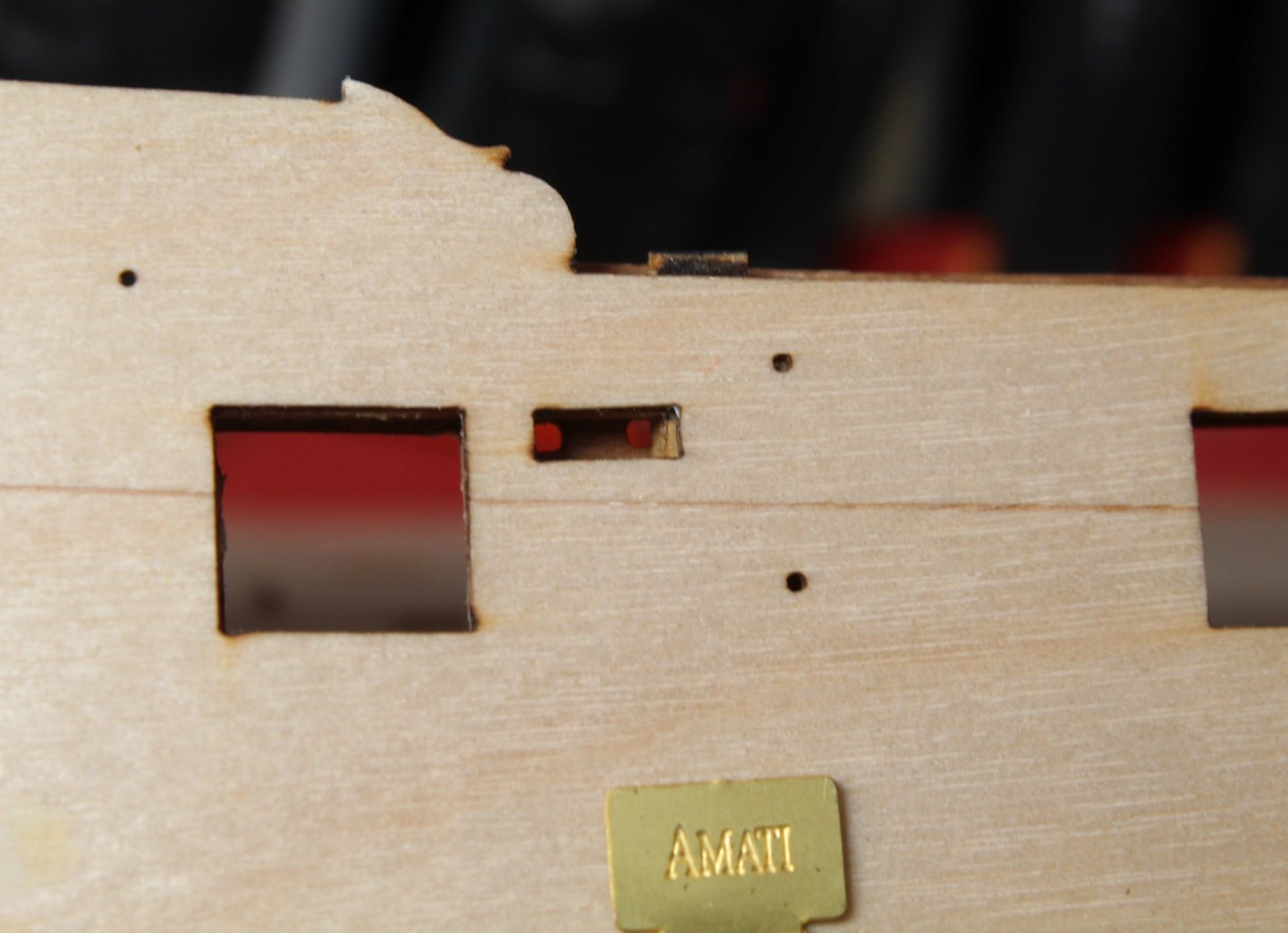
- 476 replies
-
- 5
-

-
- sphinx
- vanguard models
- (and 1 more)
-
Great advice. I have marked the position and done another trial fit. The left hand pattern has now been glued in place. I have done a few visual checks and everything looks good so far. Rather than starting midships and clamping fore and aft this time I started at the bow and worked my way back.
- 476 replies
-
- 3
-
-
- sphinx
- vanguard models
- (and 1 more)
-
Thanks, I do feel better now both patterns have been removed without any damage to the hull or patterns.
- 476 replies
-
- 2
-
-
- sphinx
- vanguard models
- (and 1 more)
-
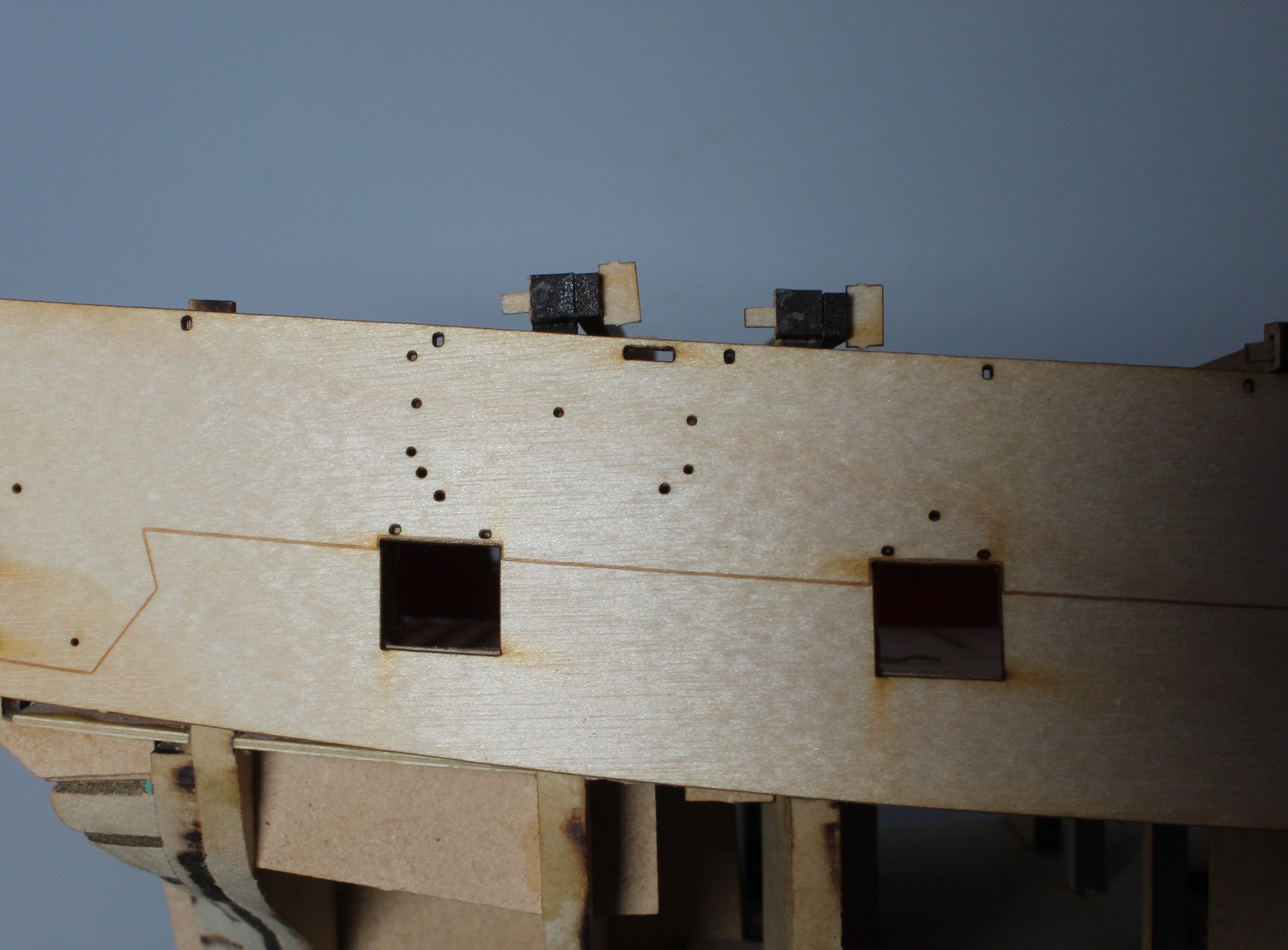
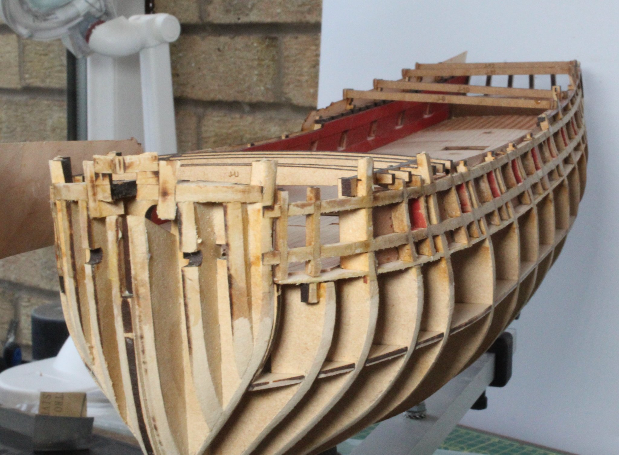
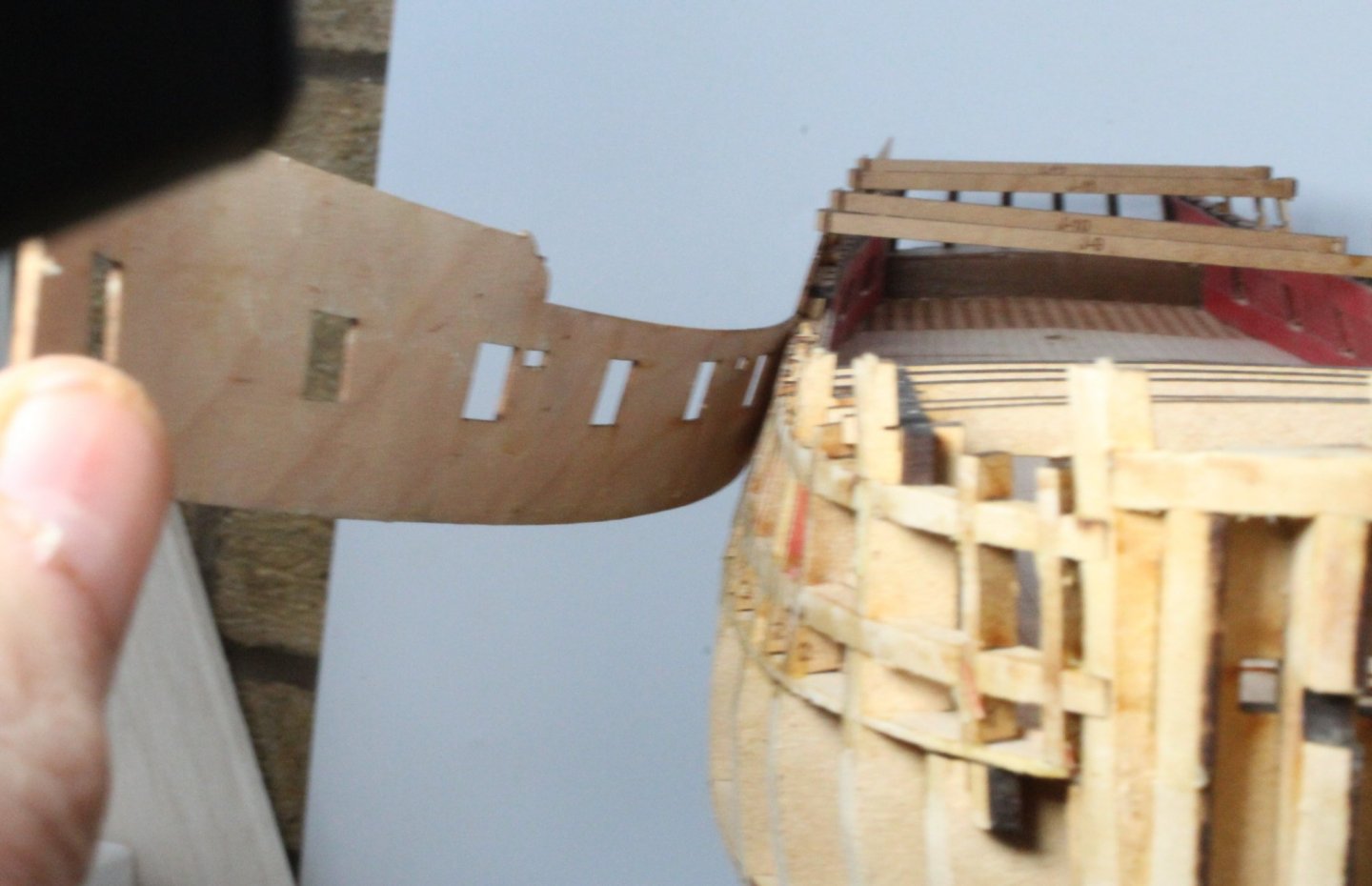
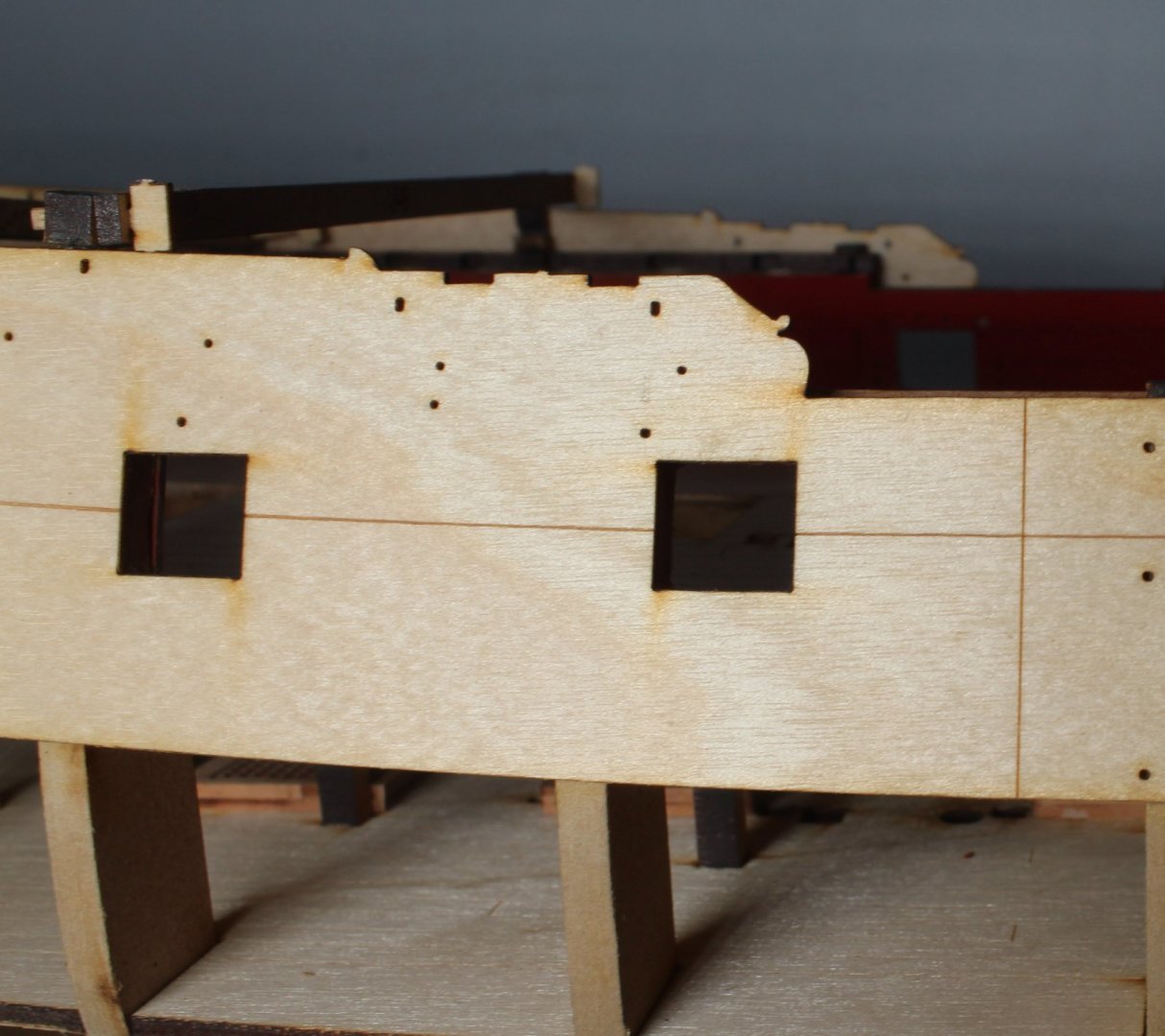
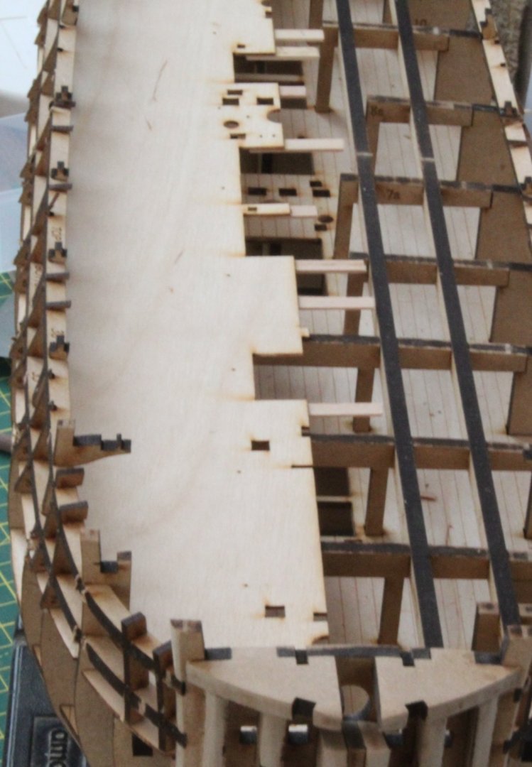
I started sorting through the 1mm x 650mm by 5mm 1st planking strips this morning, 24 were measured at greater than 1mm thick, 19 were measured at being between 0.9 and 0.99mm thick and the remaining 6 were between 0.8 and 0.89mm thick and 1 measured 0.75mm thick. I also have 11 x 1m x 5mm planking strips from my stock of materials which are greater than 1mm thick. I can plank the hull starting with the either the 0.8 to 0.89mm group (or the > 1mm group) and then move to the 0.9 and 0.99mm group and finally using the remaining group. Next I removed all the clamps from the upper patterns. It turns out I made a really mess of fitting the upper patterns. It is clear I did not pay as much detail to fitting the patterns as I thought I had. The right hand pattern look good at the midships which is where I started with the the glue and clamping process. It looks Ok at the stern also, maybe a fraction low at the last gun port opening but that could just be the camera angle Now take a look at the bow. I have no idea how I managed to misalign the pattern. I was convinced I had checked and checked again as the patterns were being clamped, but clearly this was not the case. I do remember releasing the clamps and around the bow at one point as I needed to readjust the position of a couple of them. I assume this is where the error occured. It is not a good look. I then took a closer look at the left hand pattern I noticed it would need shifting both vertically (around the bow) and laterally as a small edge of the right hand edge of the vertical gun port patterns were visible. In the past I would have lived with this error and attempt to cover up the mistake my trimming the gun ports and top edge of the upper patterns. Armed with a jug of warm water, a paint brush and craft knife I decided I should try to remove the upper patterns and start over again. Starting at the bow end I brush copious amount of water into the glued joints and then very gently eased the upper pattern away from the hull using the craft knife blade to break the glue seal. In what seemed like an eternity, but was probably about 15 minutes the left hand upper pattern was successfully removed and no damage done. I repeated the process for the right hand pattern up to the the midships. When test refitting the the released pattern end it would run true and align around the bow area as designed. That said it is probably going to be much better to remove the right hand pattern. Once the hull has dried out it will require a light sand to remove any remains of the old glue before both patterns can be reattached.


- 476 replies
-
- 9
-
-
- sphinx
- vanguard models
- (and 1 more)
-
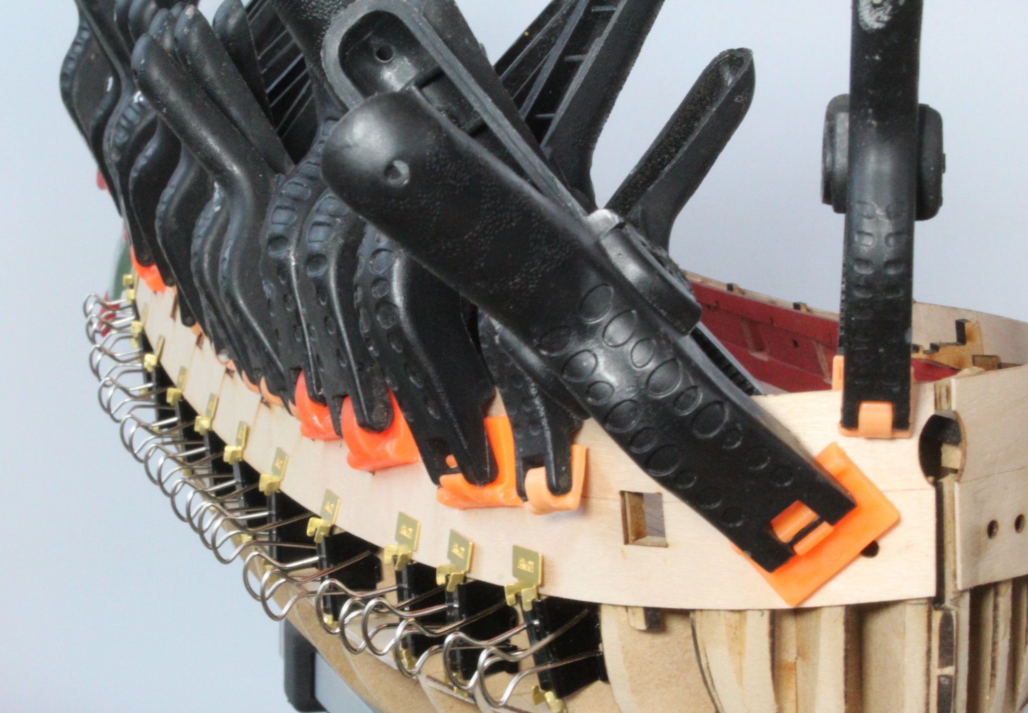
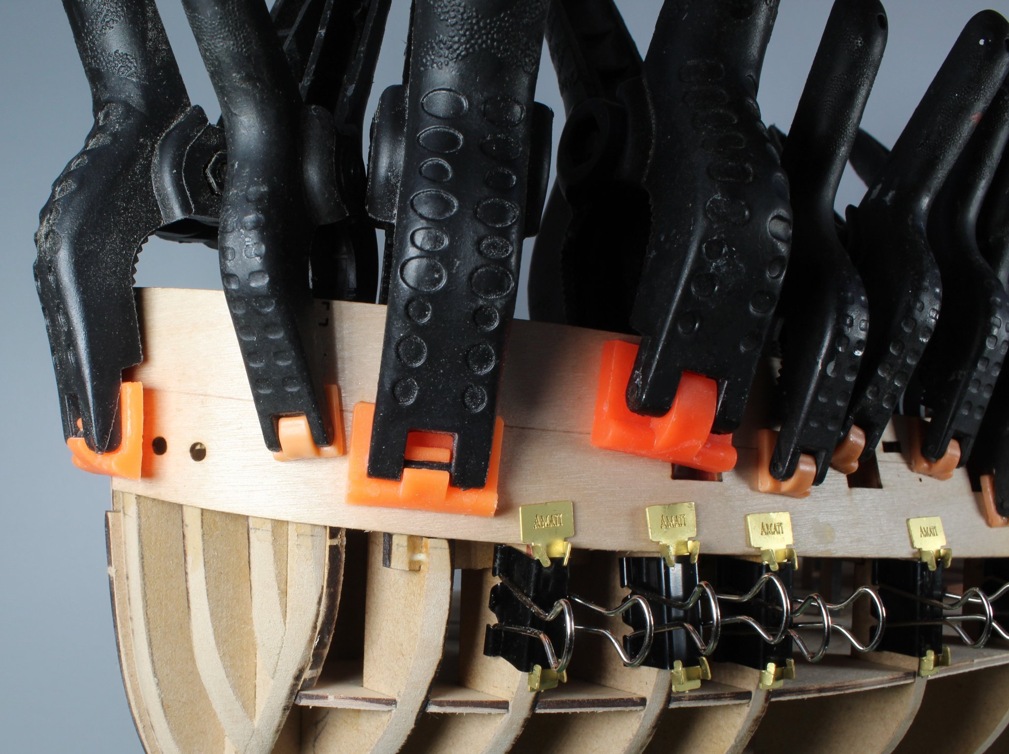
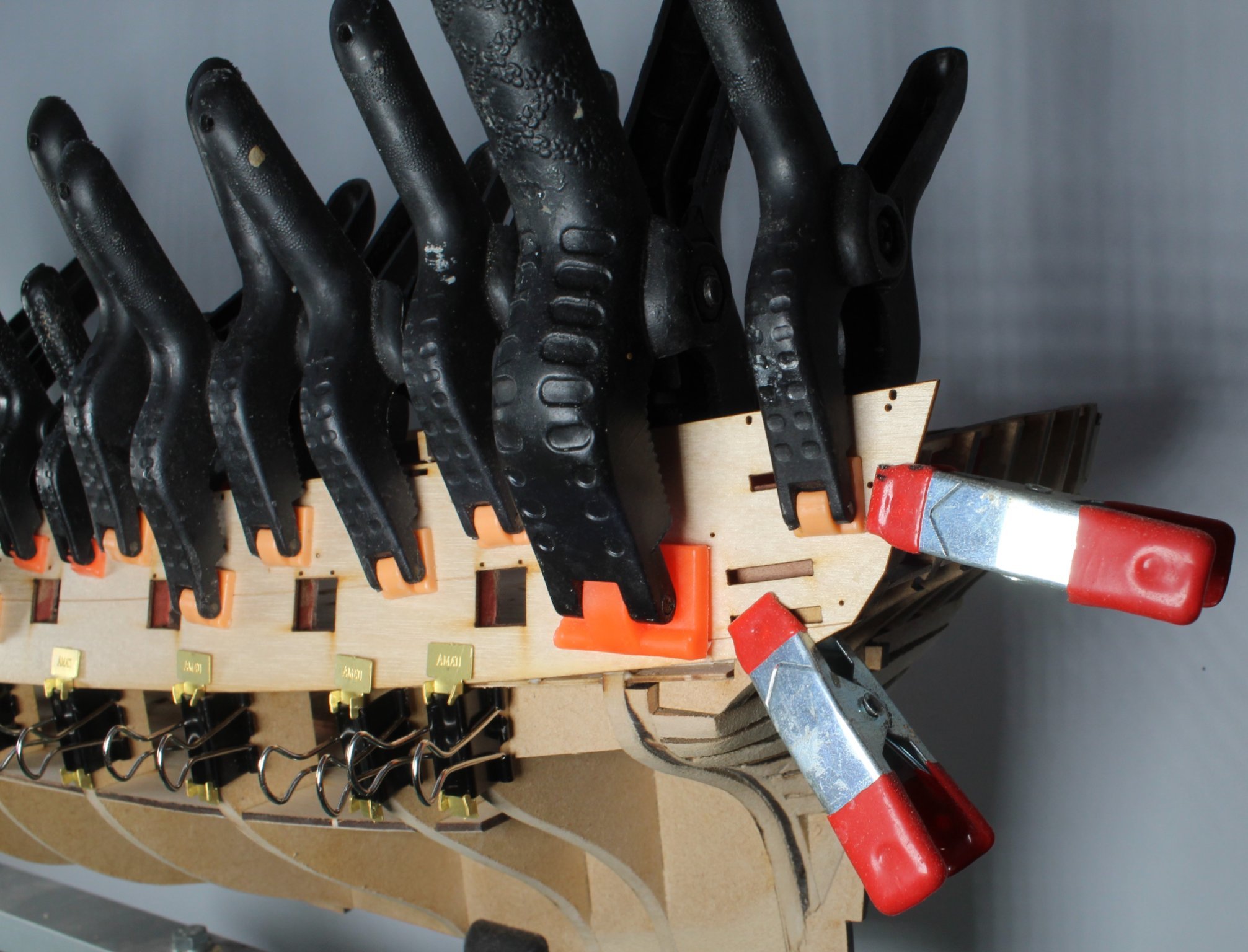
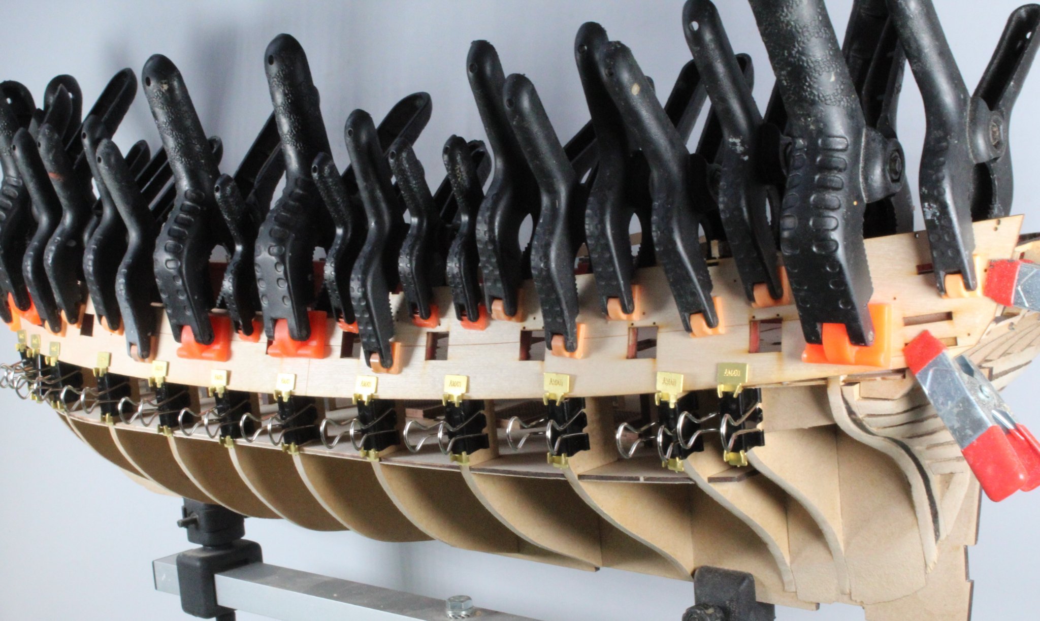
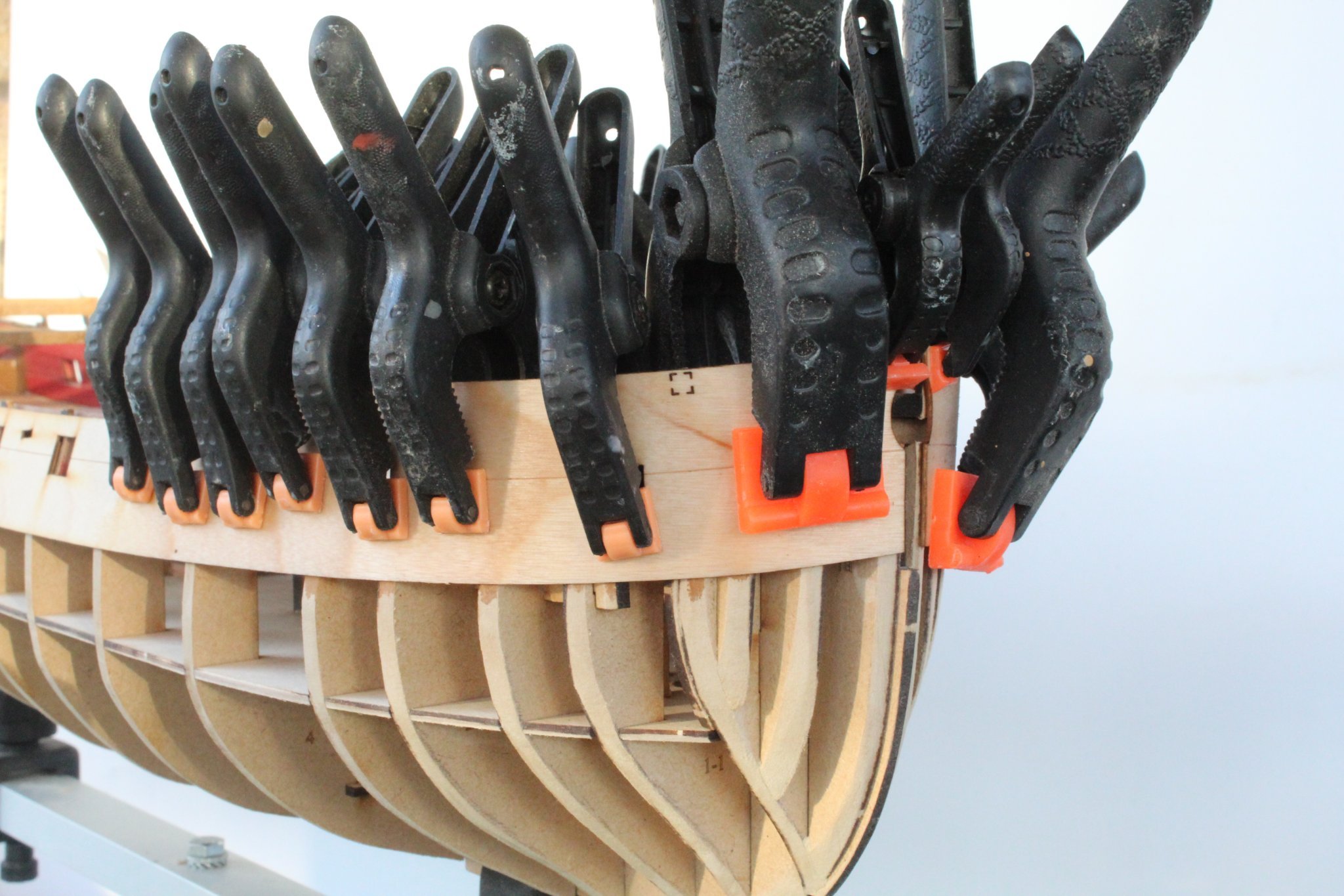
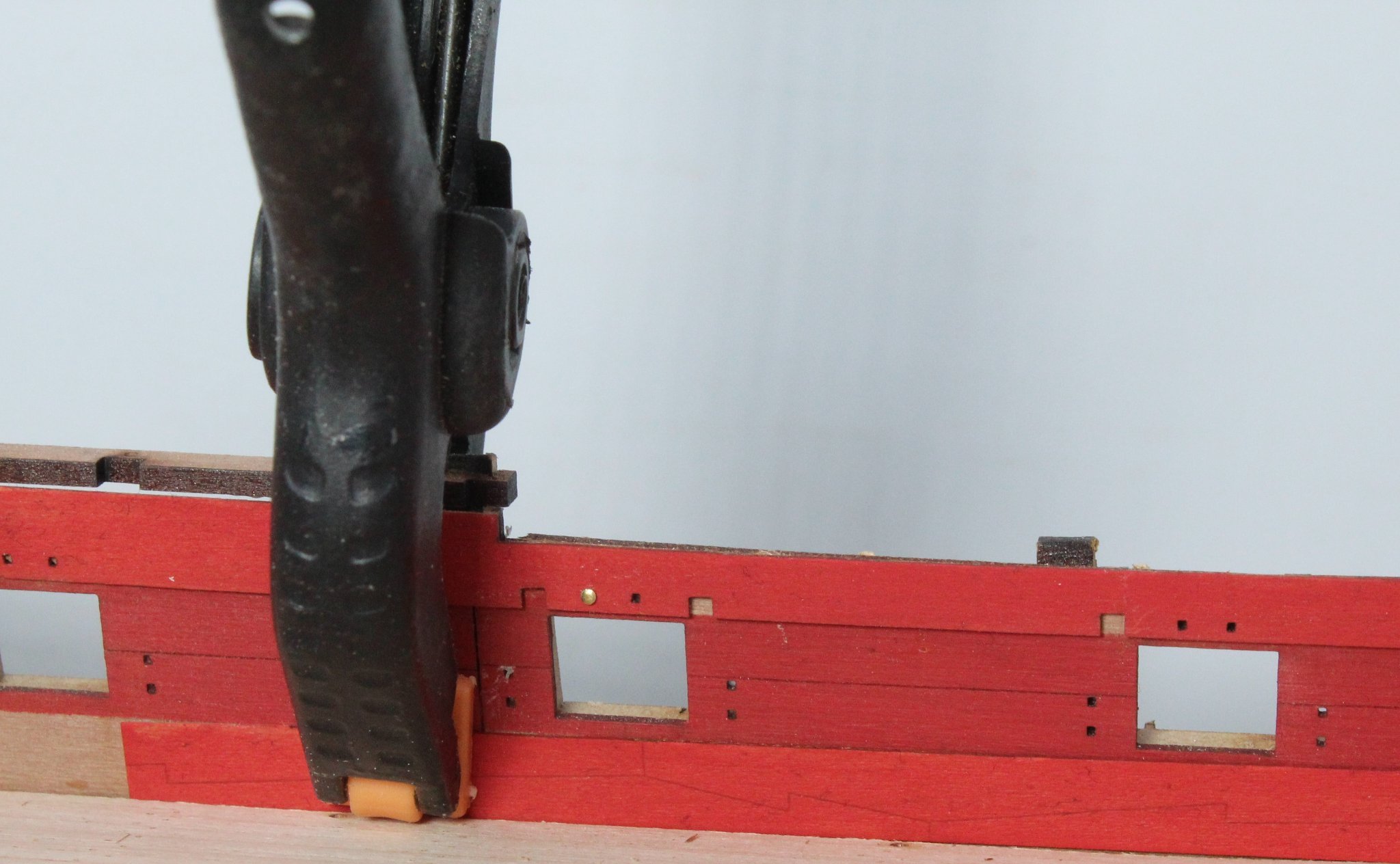
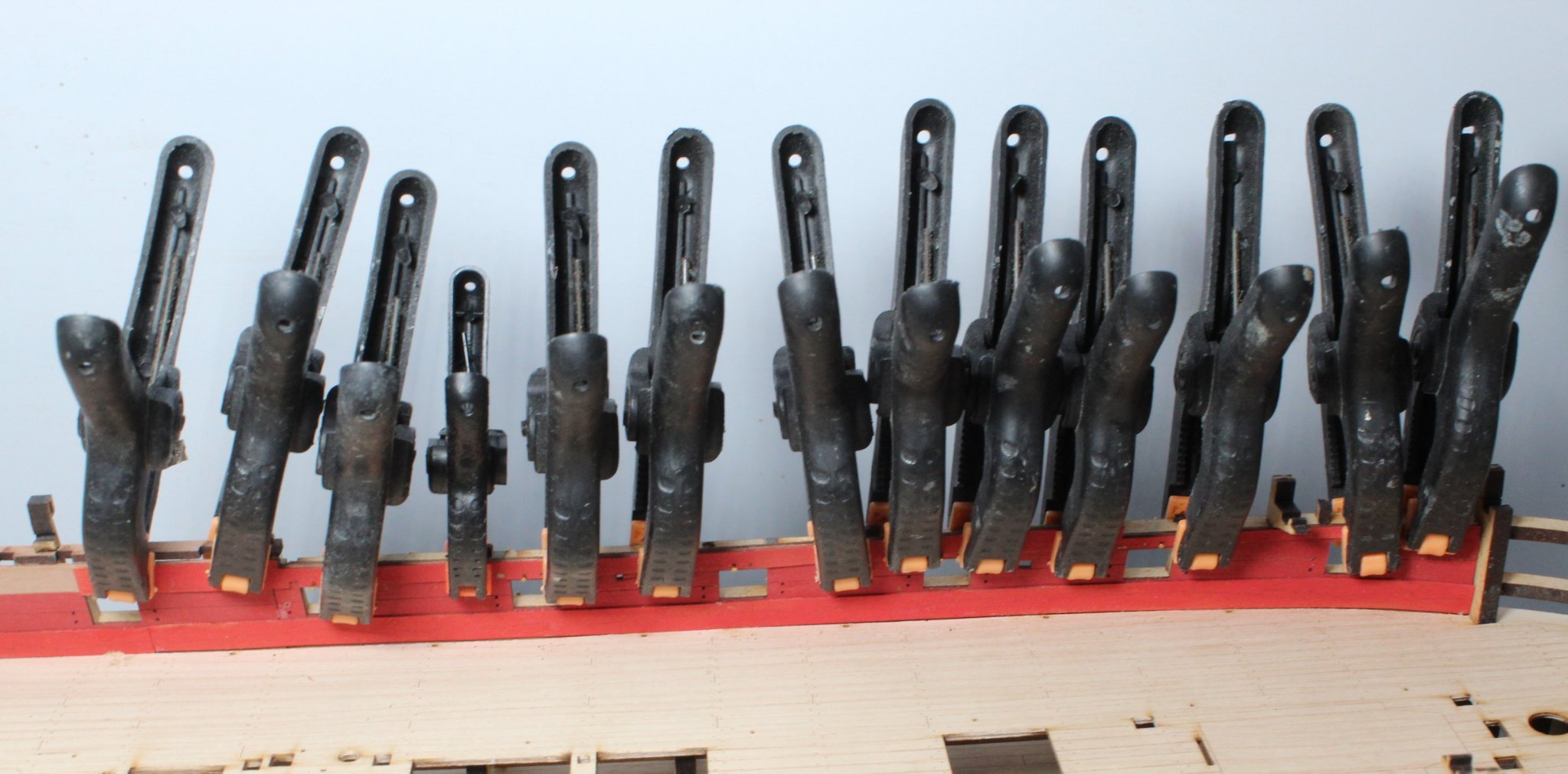
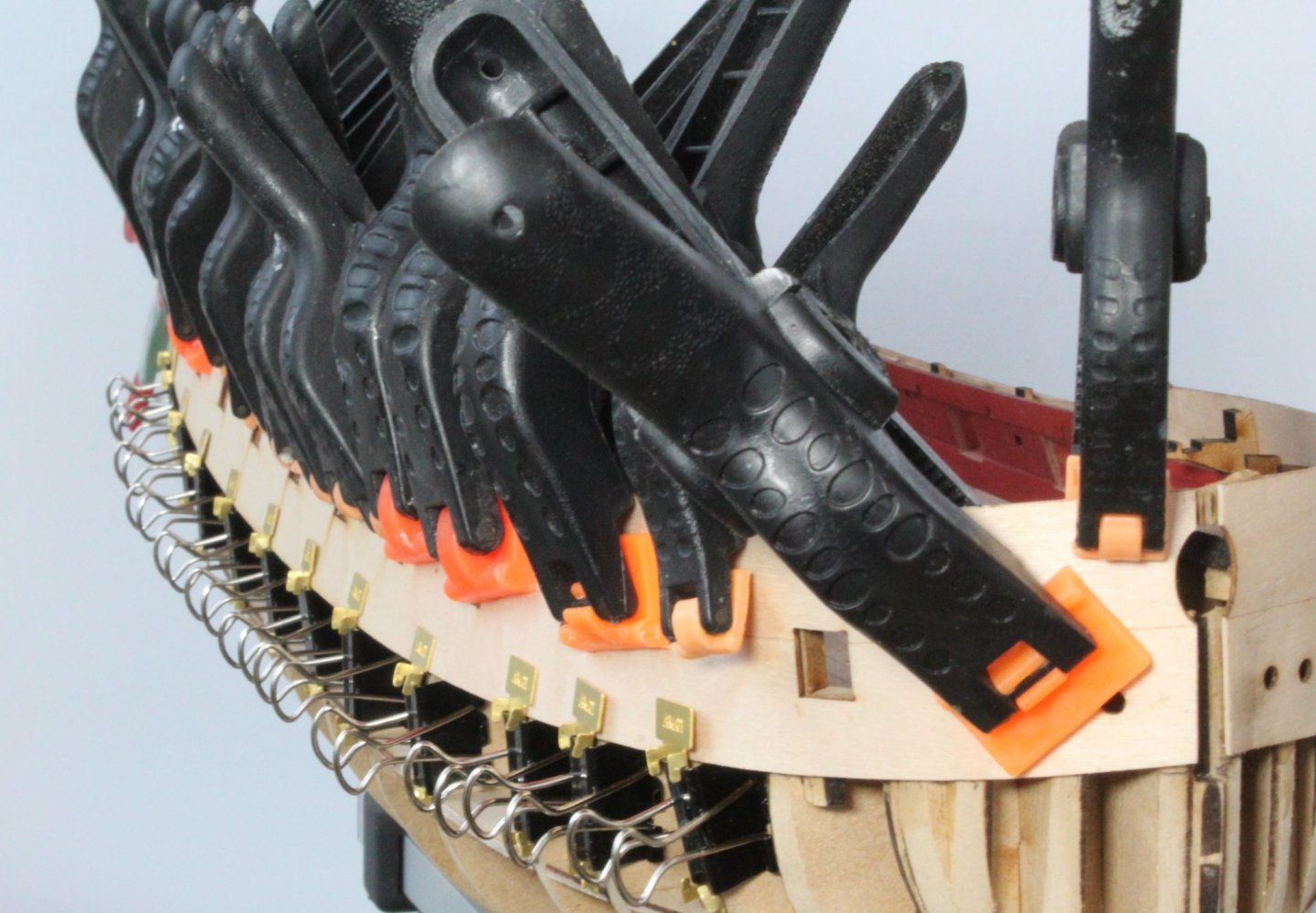
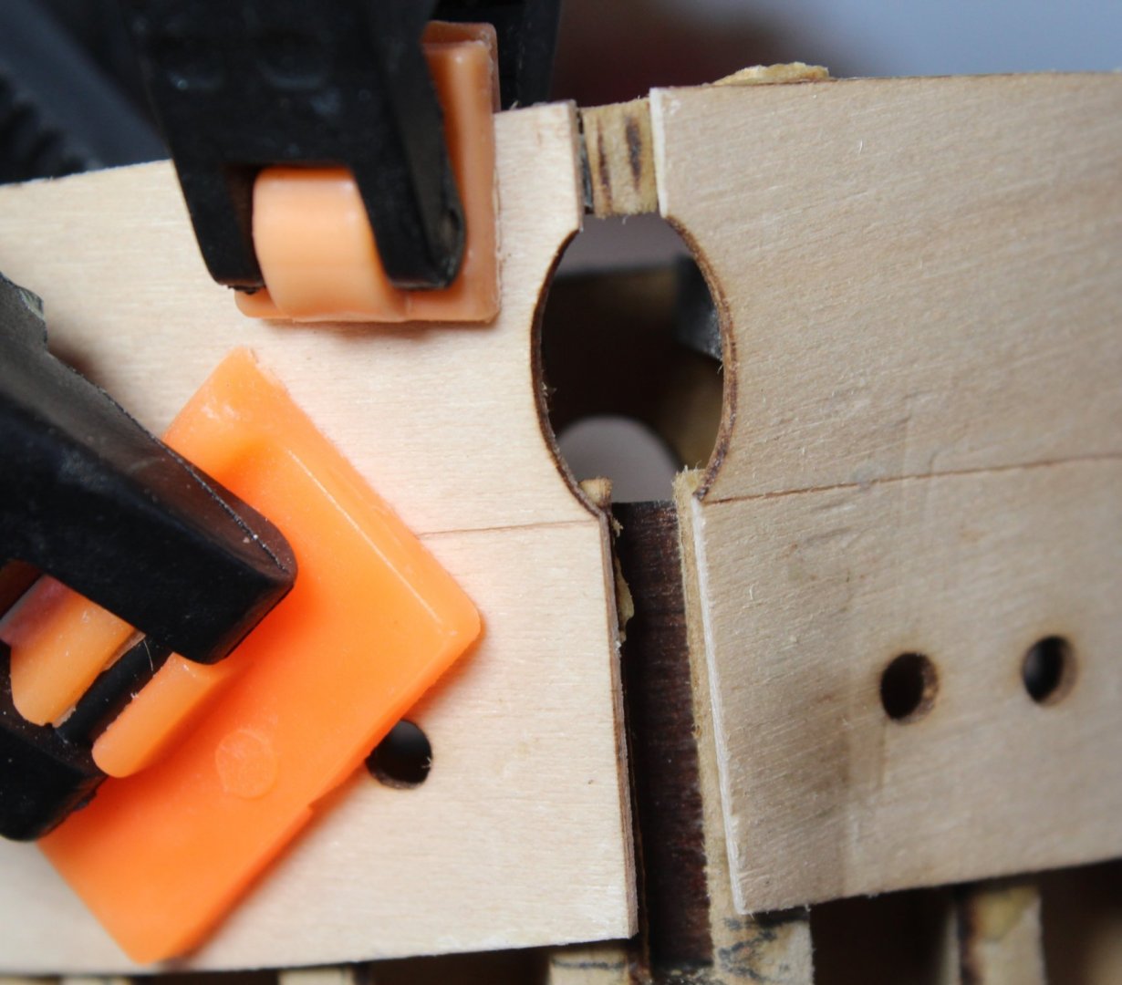
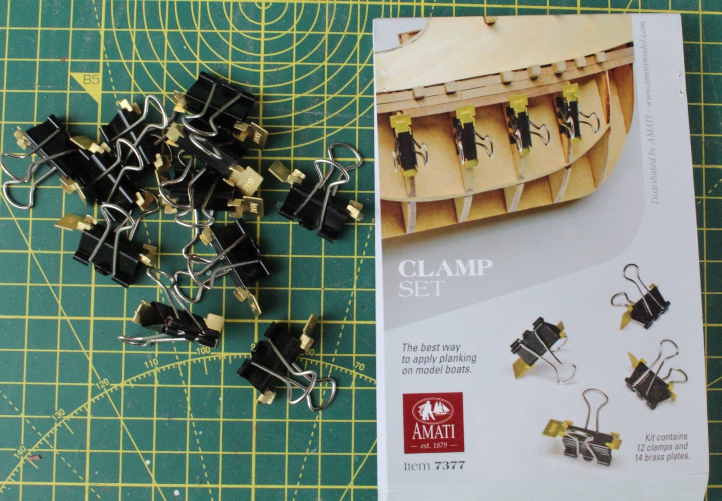
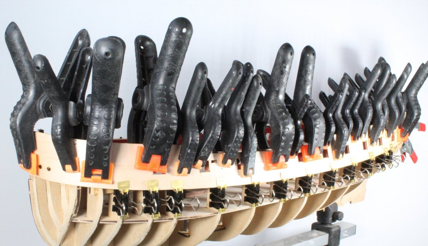
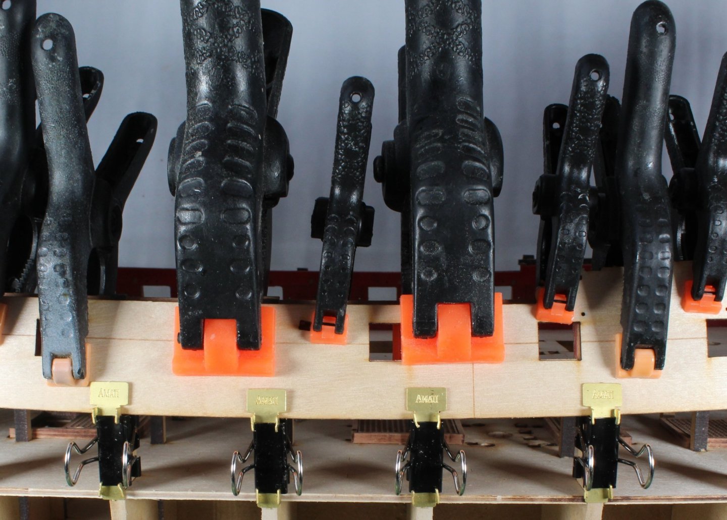
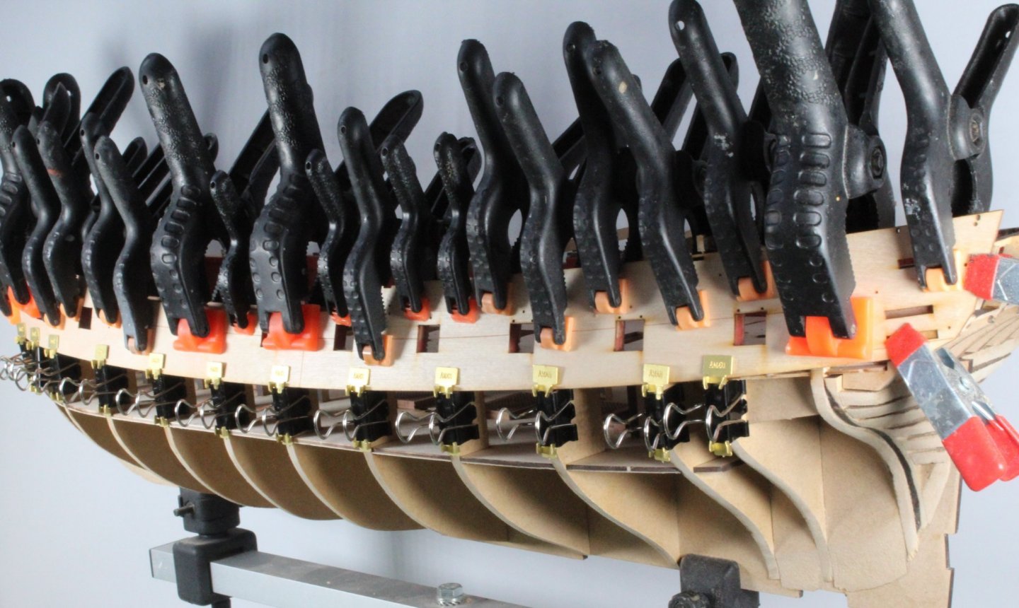
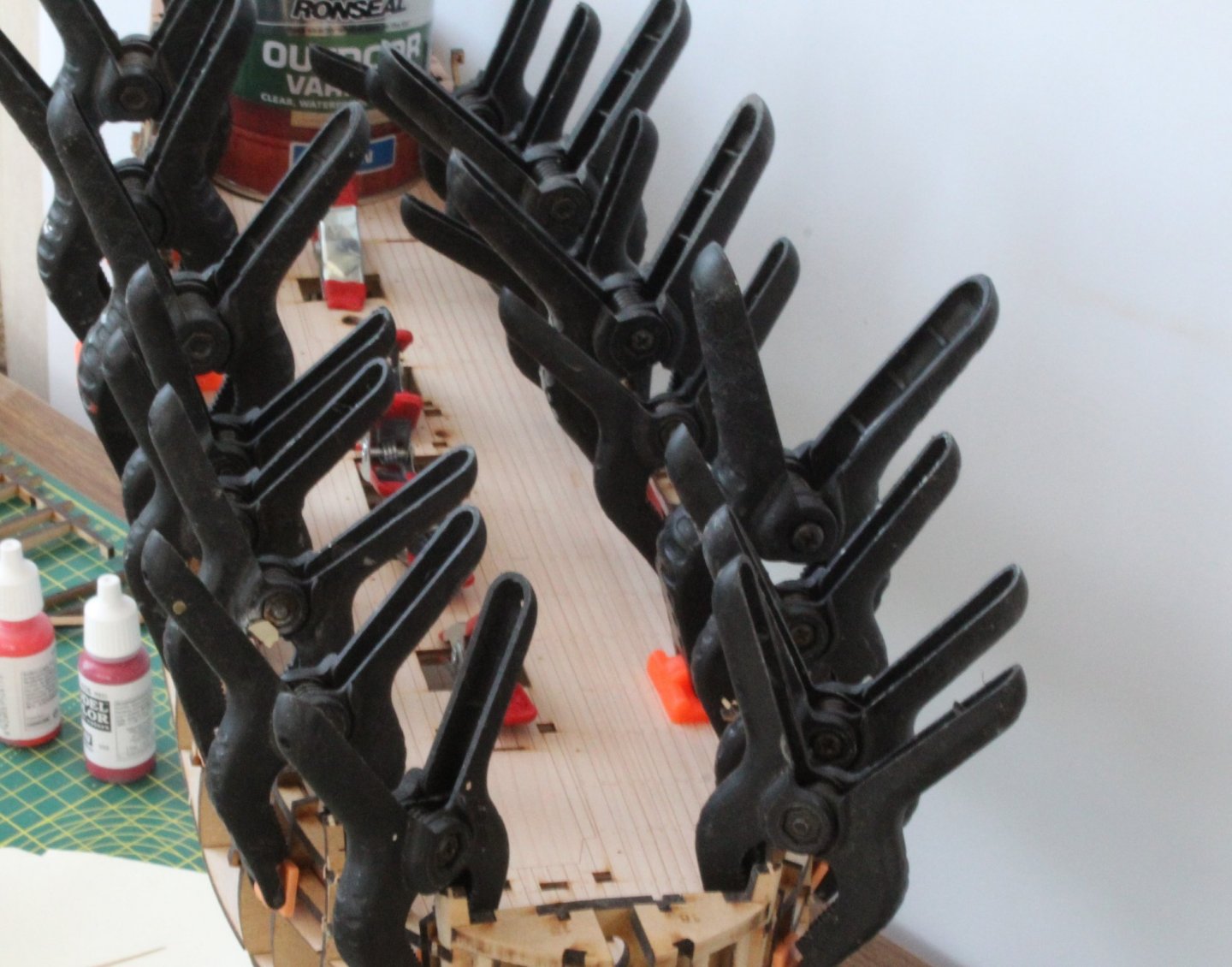
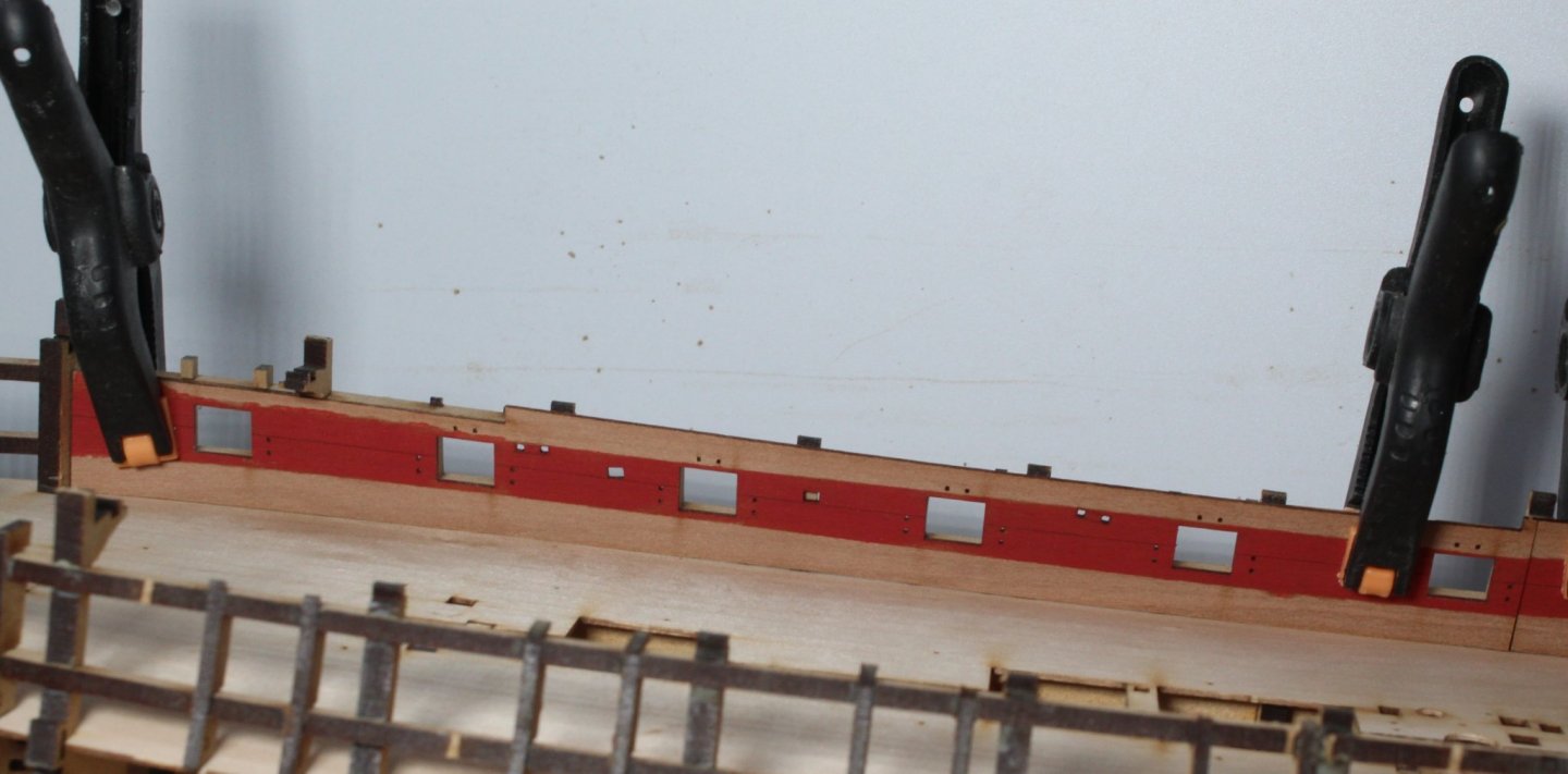
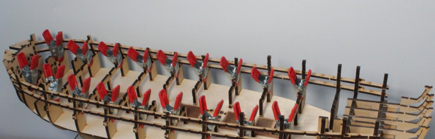
A few weeks ago I added to my tool collection when I ordered 2 sets of Amati clamps from CMB. I spent a couple of hours bending the clamp plates and fitting them to the clips over the weekend as I thought they would be useful when gluing the upper side patterns to the hull I had left the soaked upper side patterns clamped to the hull for 24 hours to allow them time to fully dry out. With the patterns still clamped in place I then used a hair dryer to blow hot air on the bow area's. After removing the clamps I was happy with the shaping of the patterns and so the left pattern has now been glued in place. I used an old paint brush to apply the glue to the hull and then carefully positioned the pattern and used several clamps to hold the pattern in place. I will allow time for the glue to cure before moving the clamps and repeating the process for the right hand upper side pattern. A sea of clamps, I think the pattern should be well secured once the glue has had time to cure. Close up of the bow Midships, the Amati clamps are really good for securing the bottom edge The stern area A final shot of all the clamps.


- 476 replies
-
- 8
-
-
- sphinx
- vanguard models
- (and 1 more)
-
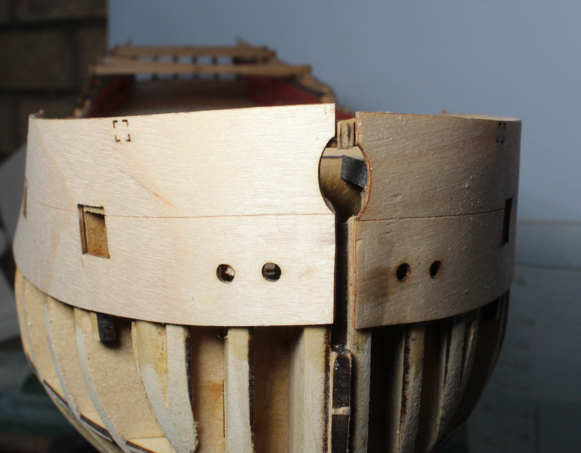
With my V1 build complete, I am not adding the masts, yards and rigging I have been making slow and steady progress on my V2 build which will be rigged. So far on the V2 build I have avoided many of the silly errors I made on my V1 build. I have reached the stage of soaking and clamping the upper hull side patterns to the hull, which will be left overnight to dry. I have done some checks and marked the correct position of the lower stern counter. To do this I clamped the stern fascia to the hull, ensuring it sat 2mm above the bulwark pattern as per steps 149, 202 and 313 of the build manual. I then added the upper counter pattern followed by the lower counter pattern. By taking much more time and care I believe I will not repeat my V1 build errors on the V2 build. Click on the following link for my V2 build log V2 Build Log


-
The excess material on the inner bulwark gun port openings were trimmed so they are now the same size as the MDF framing. I started with a craft knife to remove the bulk of the excess material and then switched to my needle files to neaten the edges. I have also sanded the stern frame patterns and marked the position of the lower counter pattern, please see my previous post in relation to this. Next up is the fitting of the upper hull side patterns. To start this process both the left and right side patterns were soaked in hot water for 45 mins. The Sphinx hull is looking on with baited breath It was then a simple case of clamping both patterns in position. I will now leave these parts clamped until tomorrow so they have plenty of time to dry out and shrink back down to size. Once I am happy with how these patterns fit they will be glued in place. It will then be time to start the first planking.


- 476 replies
-
- 5
-
-
- sphinx
- vanguard models
- (and 1 more)
-
You could use yellow ochre between the blue and black. I did that on Speedy and it looked ok
- 505 replies
-
- 5
-
-
- vanguard models
- Sphinx
- (and 1 more)
-
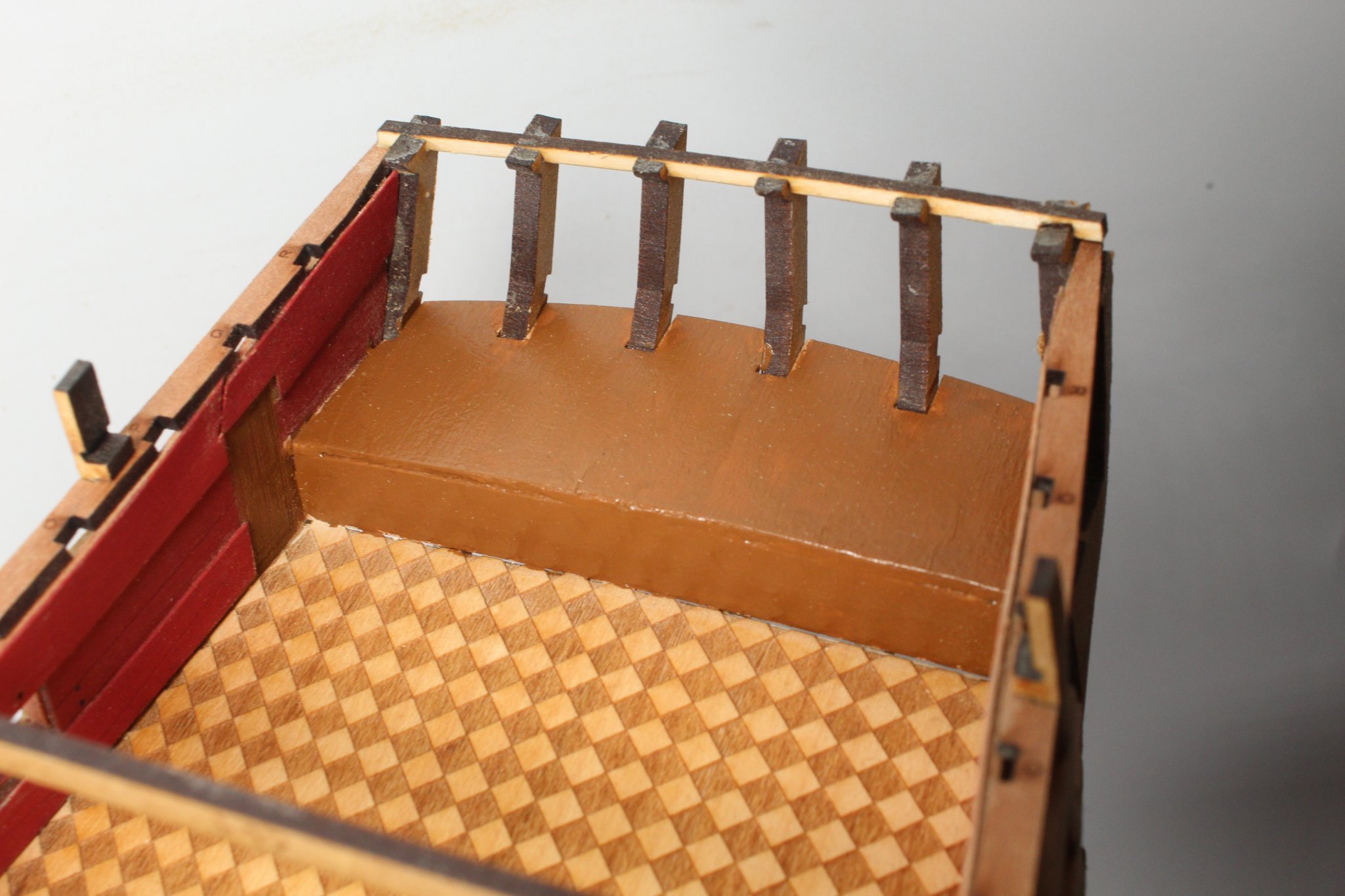
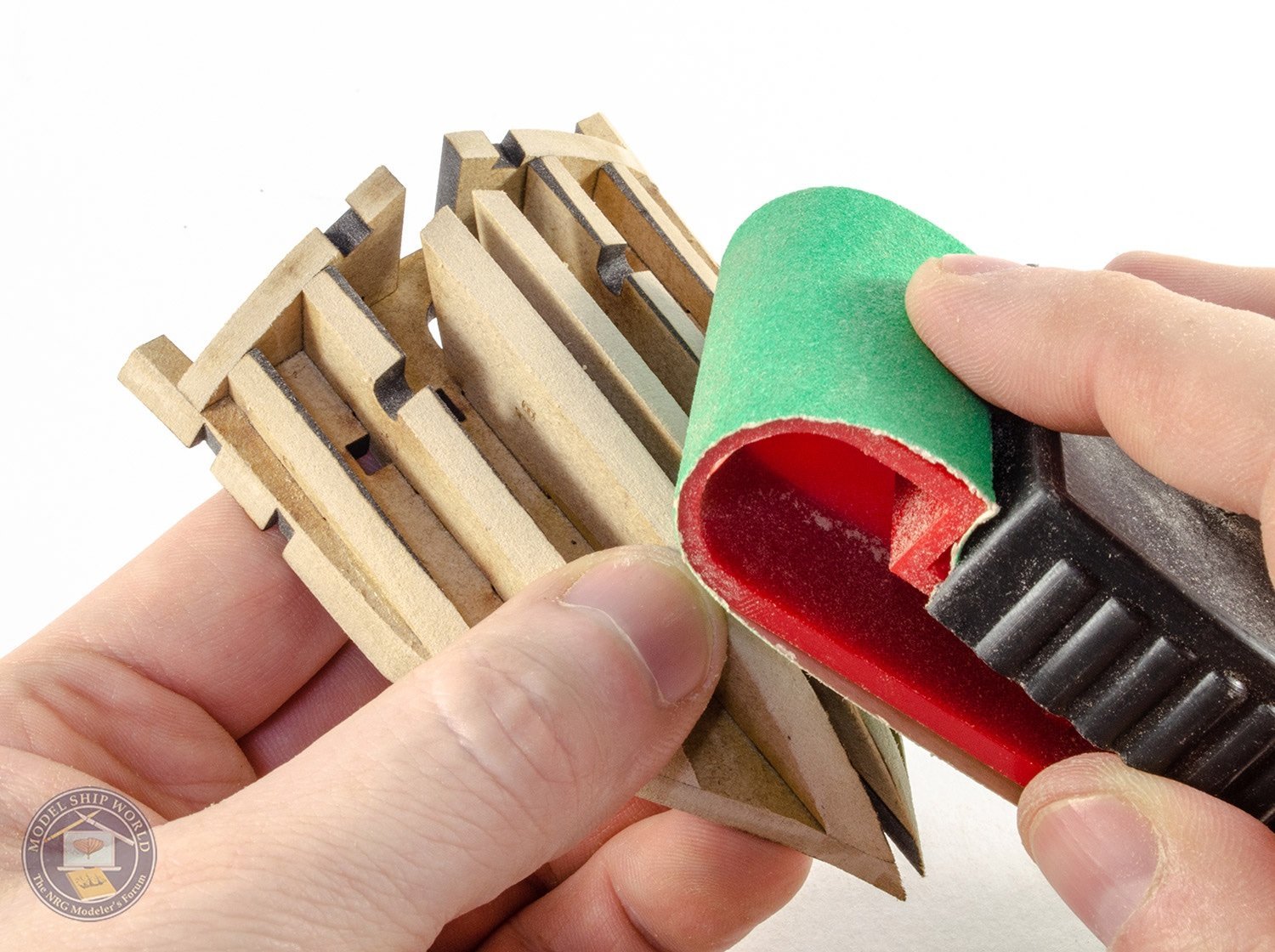
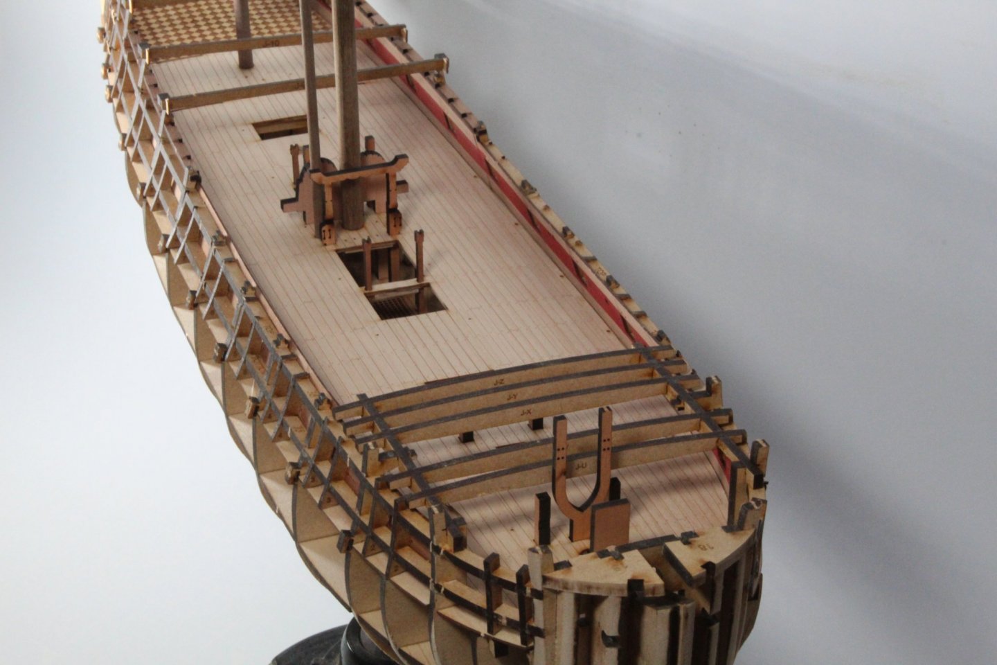
I have been able to resist my normal "bish bash bosh" building method so far and I am trying to take much more time and care with my V2 build. For the last couple of days I have been fairing the hull. I started this process by using my rotary tool to remove the excess material from vertical gun port strips. It was then a case of using 120 grit sandpaper in conjunction with my Amati Special Cleaner B7140 and florey sanding sticks to fair the hull. It took quite a bit of effort to sand the areas where the gun port strips crossed the bulkheads smooth, i.e. so there was no laser char. I only broke one of the jig holding ears during the fairing process, as can be seen below (J10) I have tried a few planks around the bow area and as far as I can I have good contact between the planks and bulkheads The stern area I have also fitted the stern cabin bulkhead and stern cabin seat patterns. Although this is not going to be visible once the quarterdeck has been fitted I debated adding some panelling to enhance the stern cabin bulkhead and stern cabin seat but in the end I opted for a WOP coat followed with a walnut paint finish. I then clamped the upper hull side patterns to the hull from midships to stern. I then took the stern fascia panel and added some tape 2mm below the top edge and clamped the fascia panel to the hull. This needs a slight adjustment as the fascia needs to be raised up a bit on this side. This side also needs a slight adjustment as it is a fraction too high at the moment. I also clamped the upper stern counter to the fascia panel. This will enable me to workout the position of the lower counter pattern. I need to remove some laser char before I can add some pencil marks to indicate the where the lower counter will be positioned.


- 476 replies
-
- 7
-
-
- sphinx
- vanguard models
- (and 1 more)
-
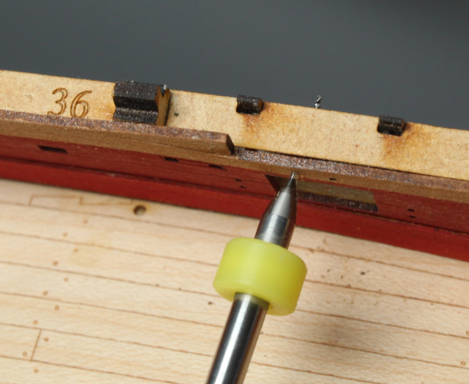
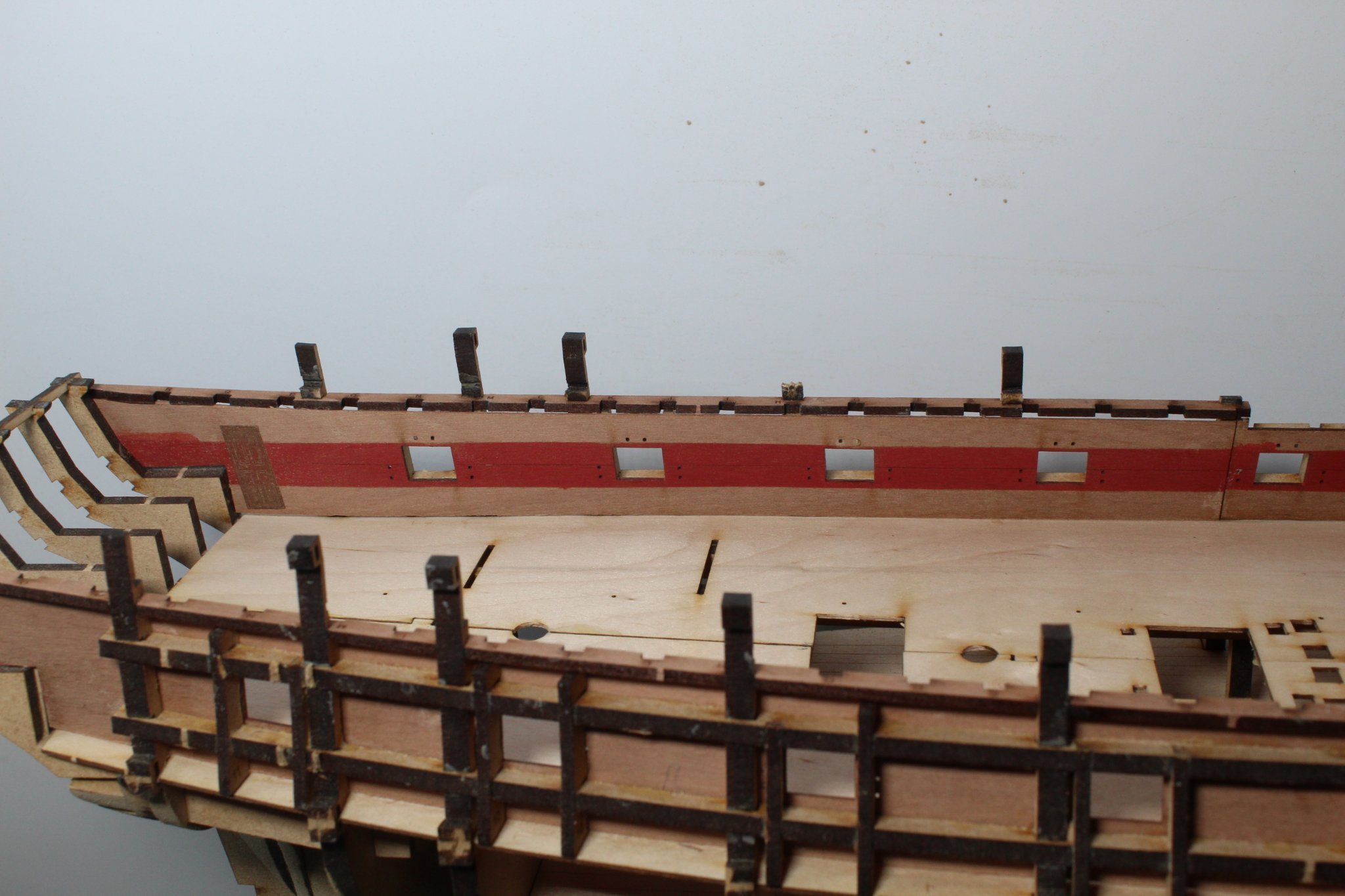
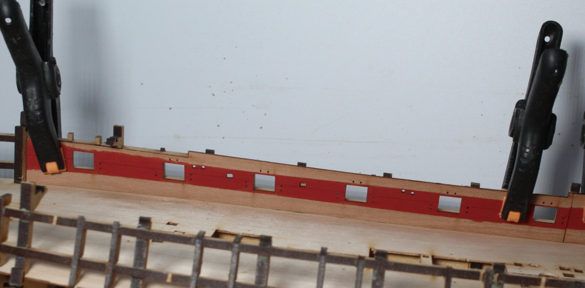
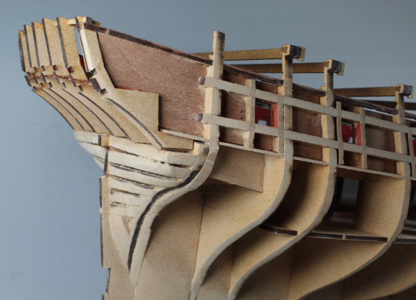
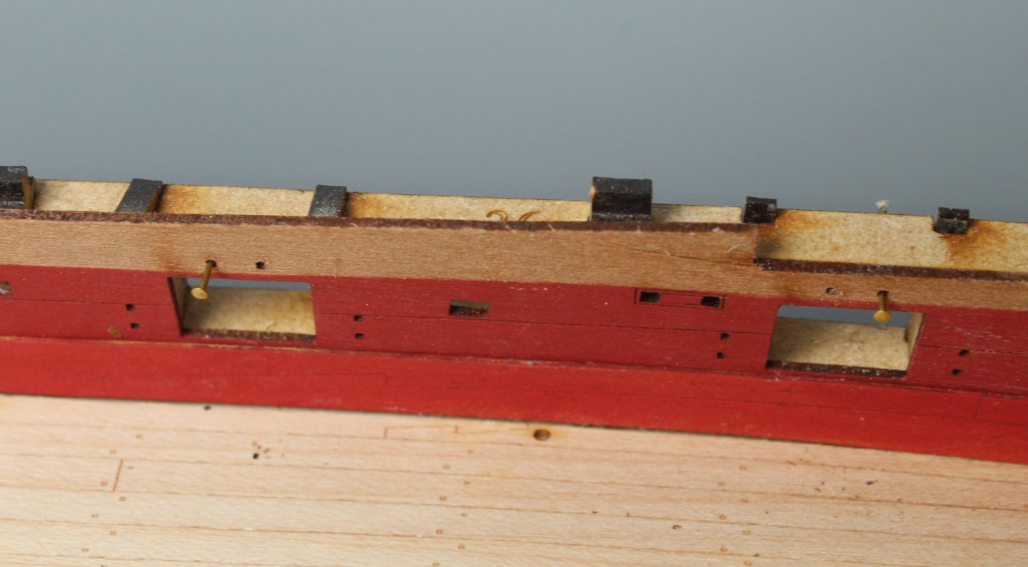
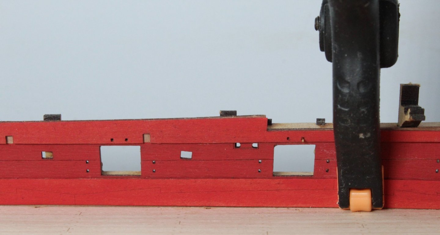
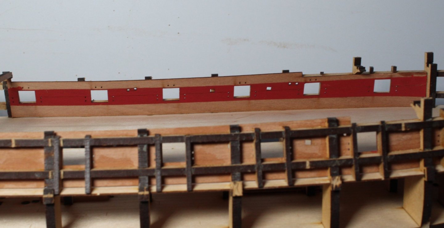
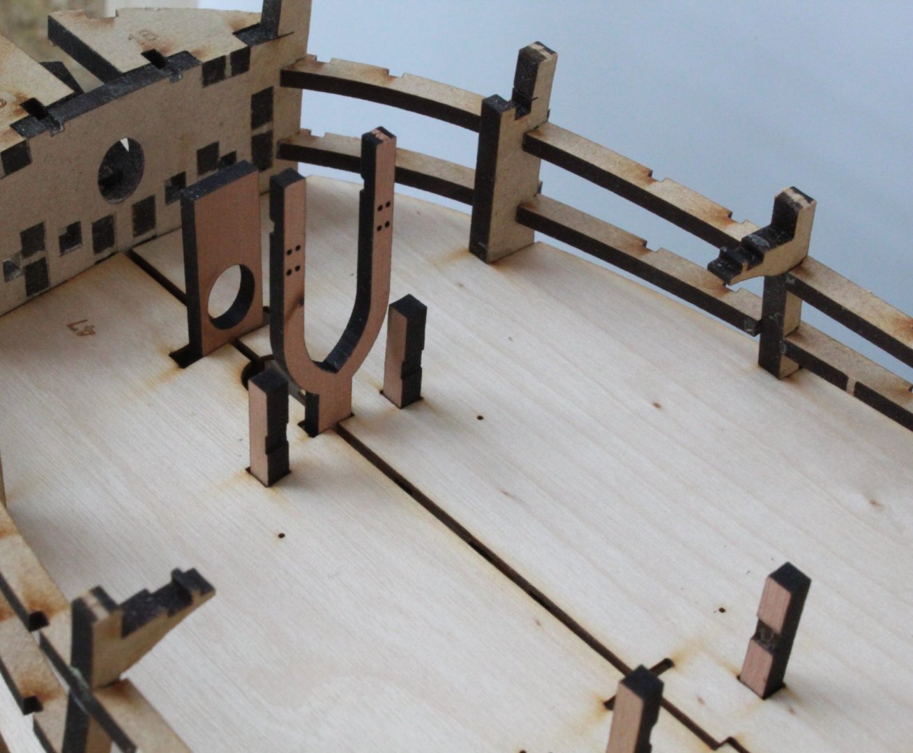
Today I started work on fitting the Lower Spirketting and Deck Clamp Patterns to the left hand side. Before proceeding with the gluing phase there were a few things I wanted to do / check. The first task was to drill through the eyebolt holes above each gun port so locating pins can be used when fitting the Deck Clamp Patterns, as can be seen in the photo below With each hole drilled I checked the pins would fit. I also test fitted an eyebolt. Using the holes the Deck Clamp Patterns were dry fitted. I decided to test fit some of the gangway deck support knees. I soon realised that I had not correctly fitted these parts on my V1 build. Now that I was happy with how the support knees should be installed the Lower Spirketting and Deck Clamp Patterns were coated with a slightly diluted pva glue mix and clamped to the hull, using the pins to ensure the Deck Clamp Patterns were correctly positioned. Front Deck Clamp Pattern clamped in place, with pins used to locate the pattern can be seen The rear Lower Spirketting and Deck Clamp Patterns Tomorrow I will repeat the above process for fitting the right hand side Lower Spirketting and Deck Clamp Patterns, noting I have already run the micro drill through the eyebolts holes so it should be a simple task of applying the glue and clamping each part in turn. When complete I might add a final coat of diluted flat red paint before applying a WOP coat.


- 476 replies
-
- 4
-
-
- sphinx
- vanguard models
- (and 1 more)
-
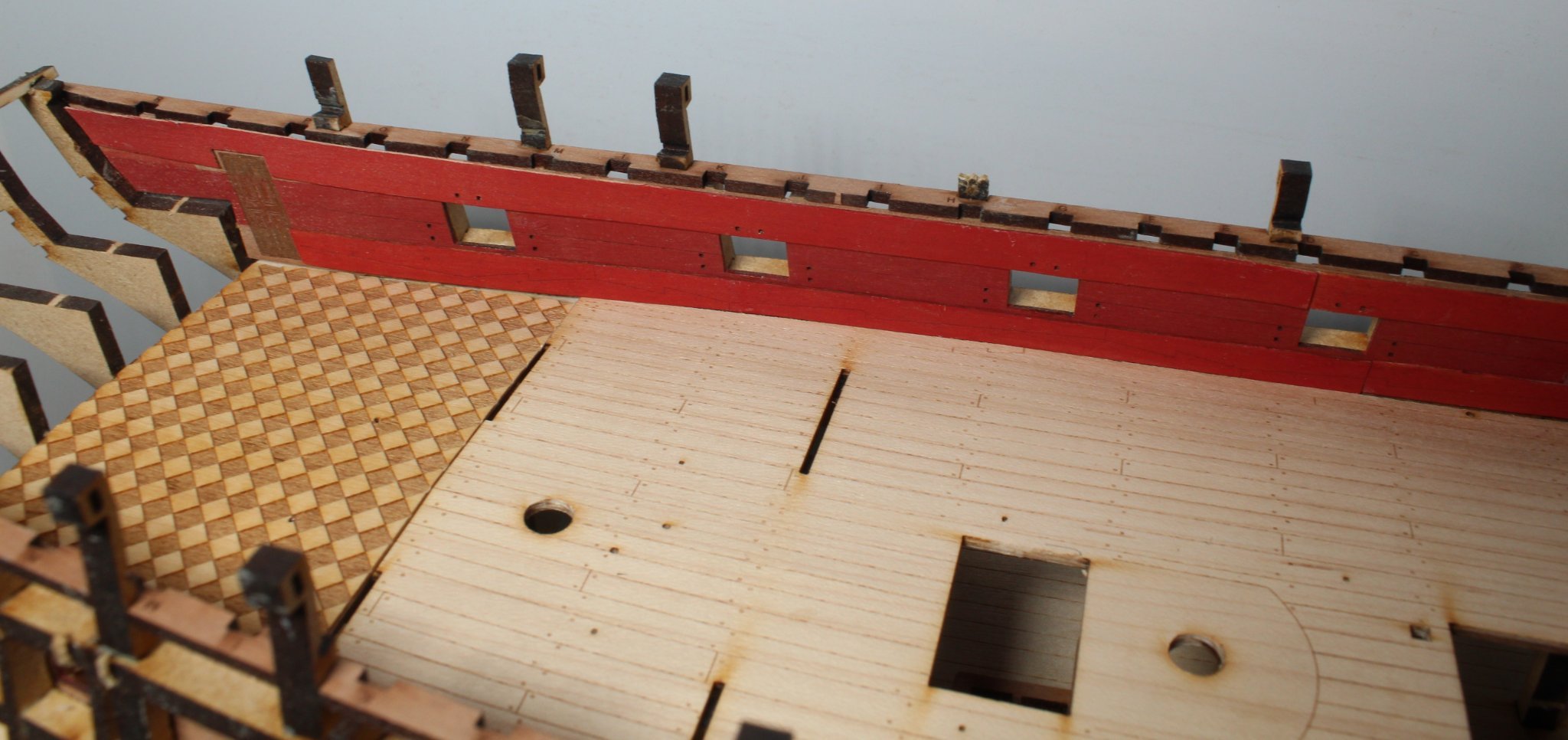
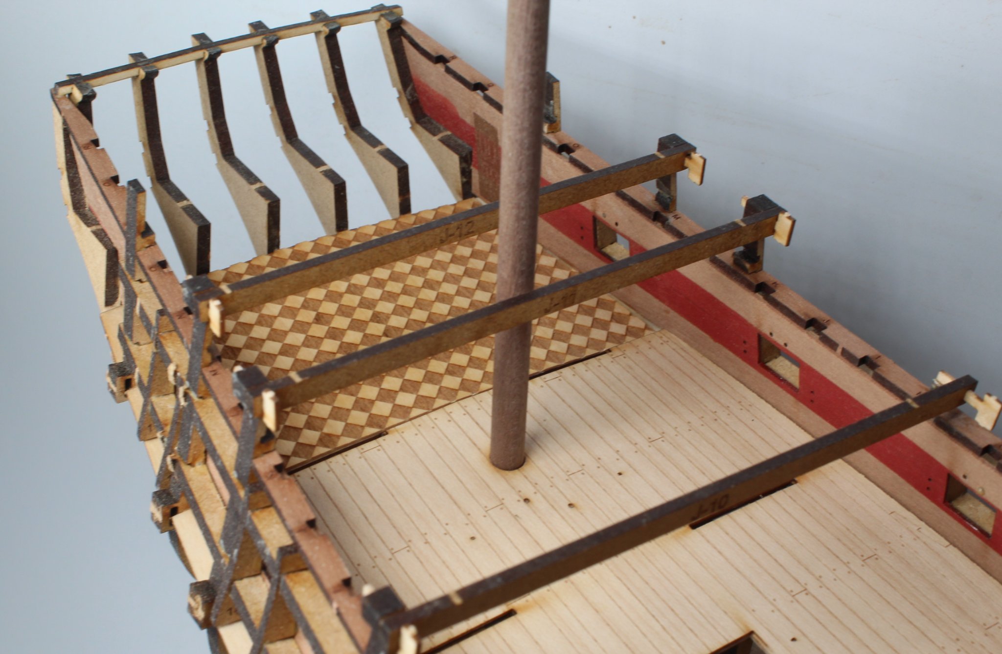
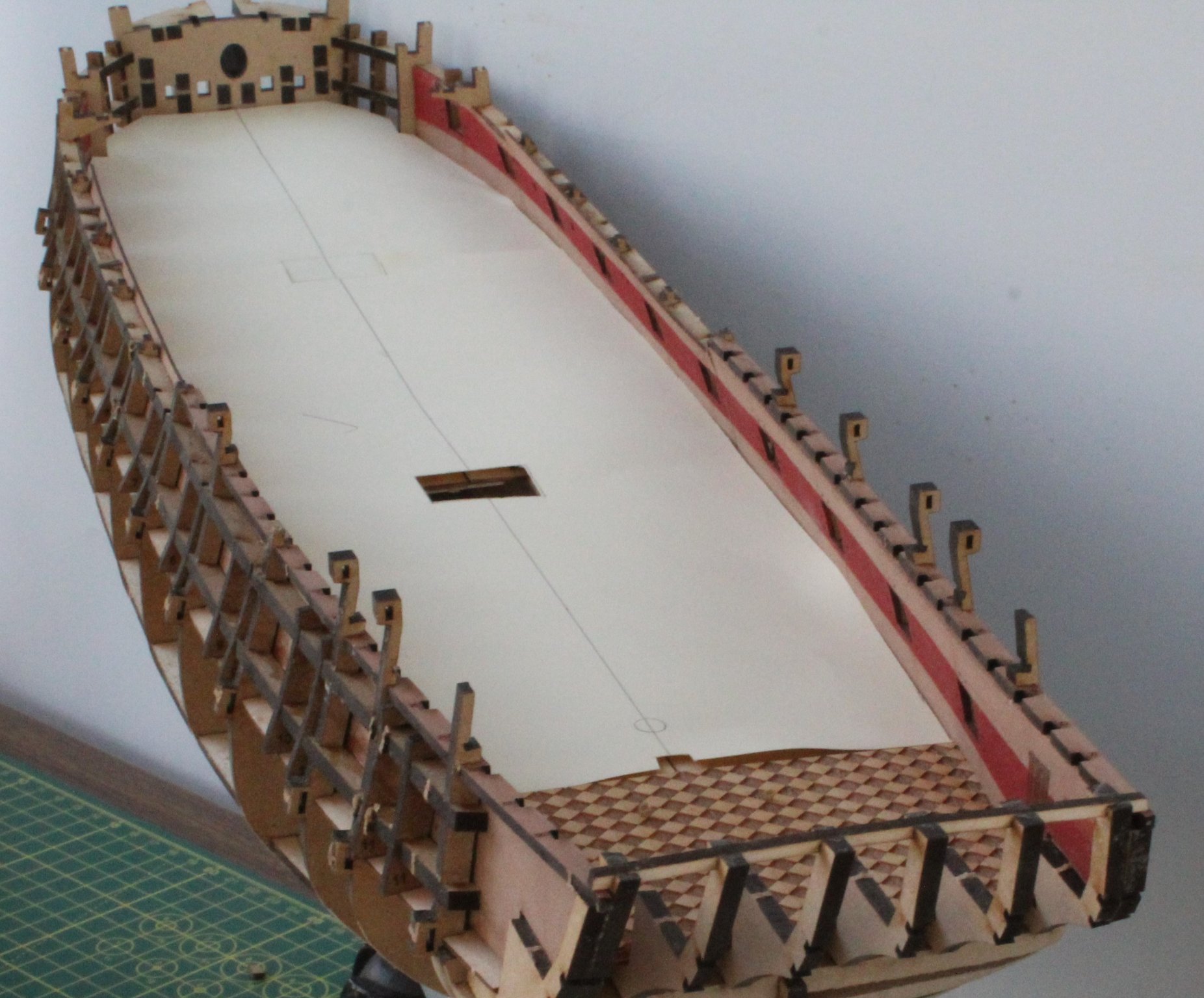
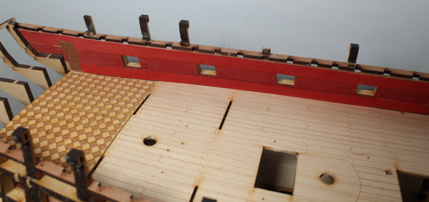
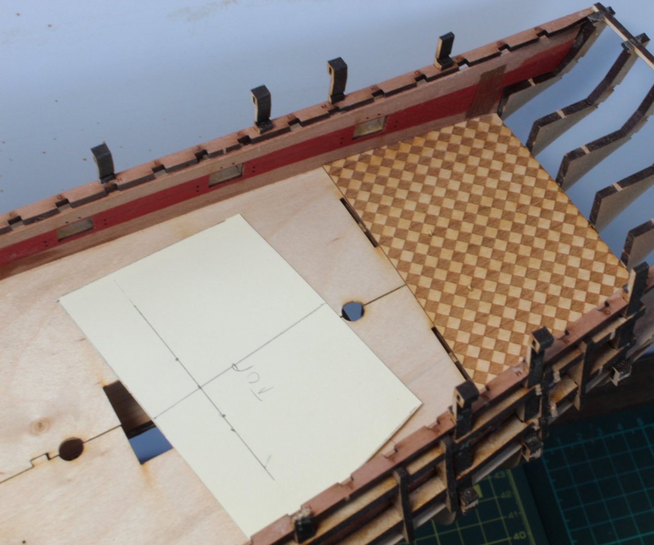
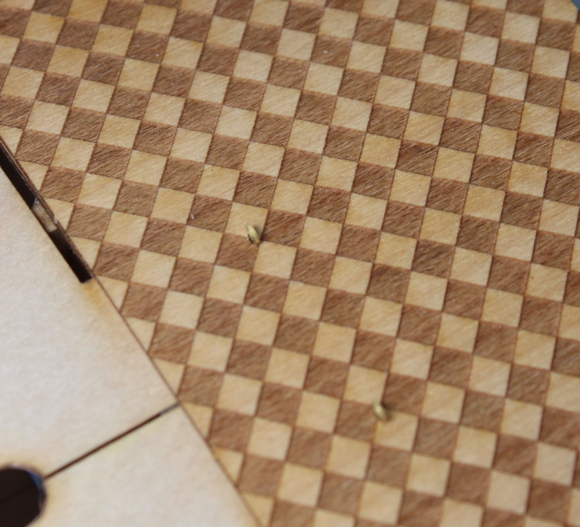
Following on from my last post I used the cardboard template to trim the main gun deck pattern. It required a small amount of sanding before it would fit. I then dry fitted the deck items the majority of which were a nice smooth fit, but as can be seen in the photo below I was unable to fit all the parts. After a little bit more fettling all the deck items were a nice smooth fit. I then applied a coating of pva to the gun deck pattern and once it was installed used clamps to hold the deck in place as the glue cured. I used a tin as a weight to hold the chequer pattern deck in place. After the glue had cured the clamps were removed and I rechecked the dry fitting of the deck items. I also fitted the space jigs. Everything was a really good fit. I am really pleased I took my time with the fitting of the deck pattern as the gun deck is a much better fit compared with my v1 build.


- 476 replies
-
- 7
-
-
- sphinx
- vanguard models
- (and 1 more)
-
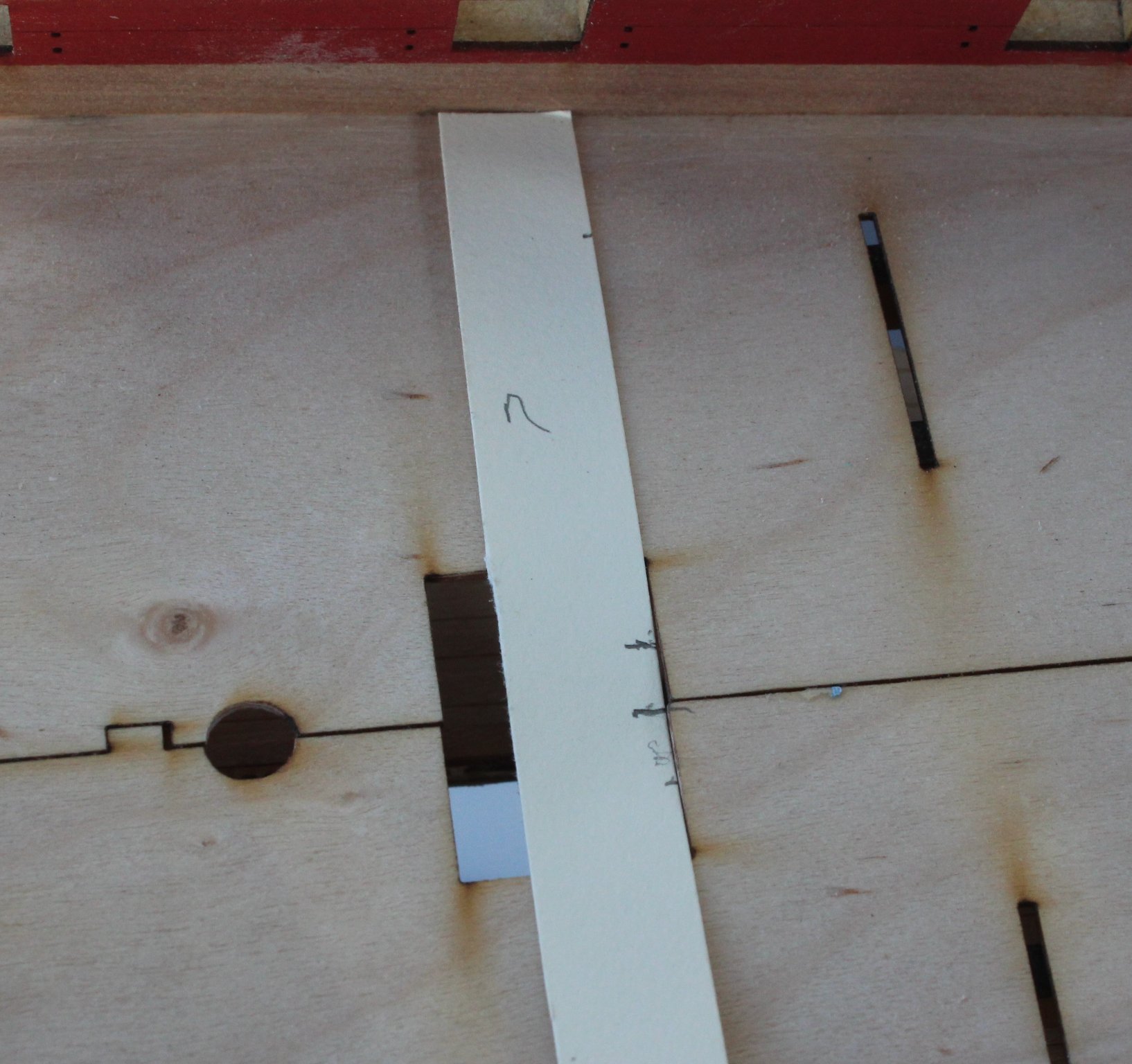
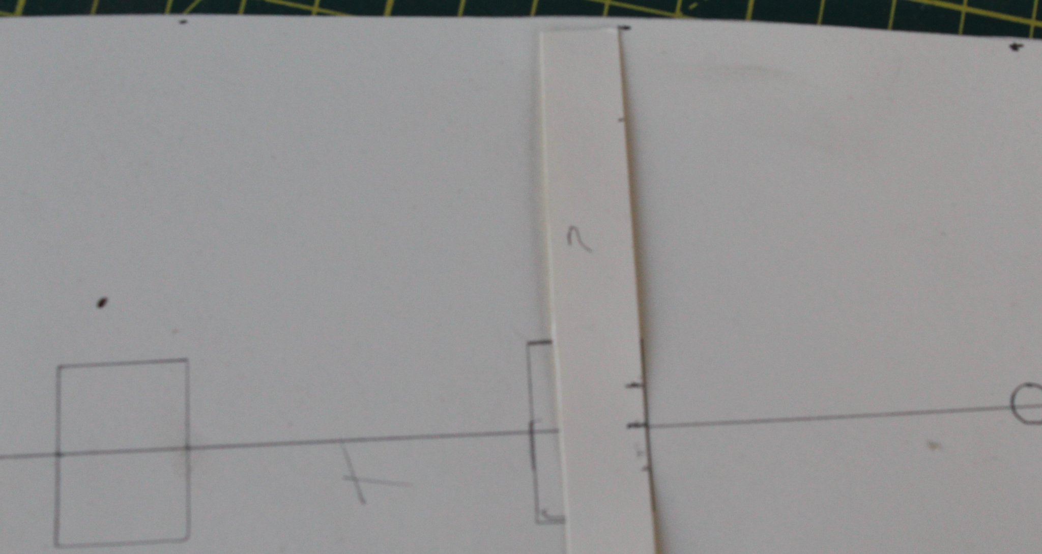
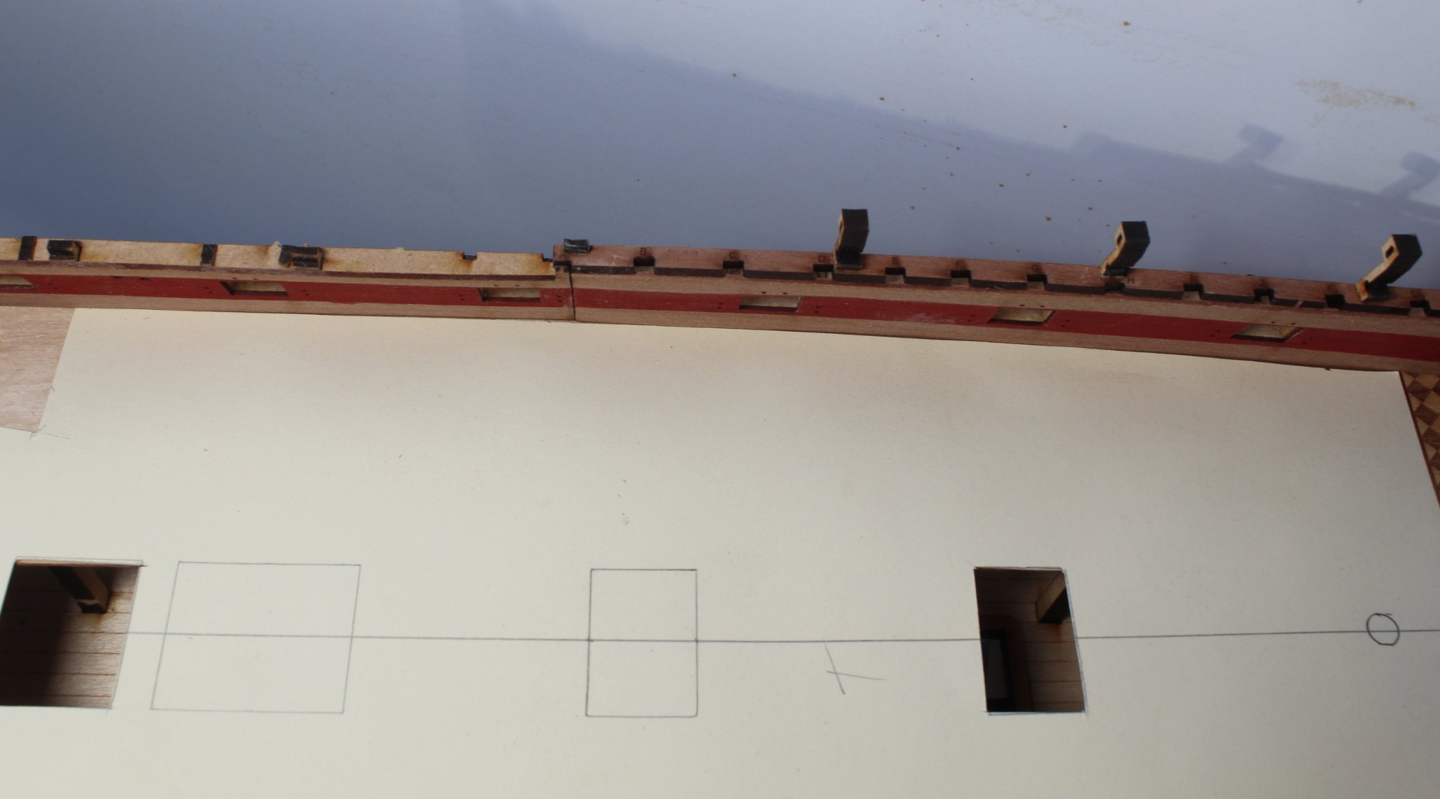
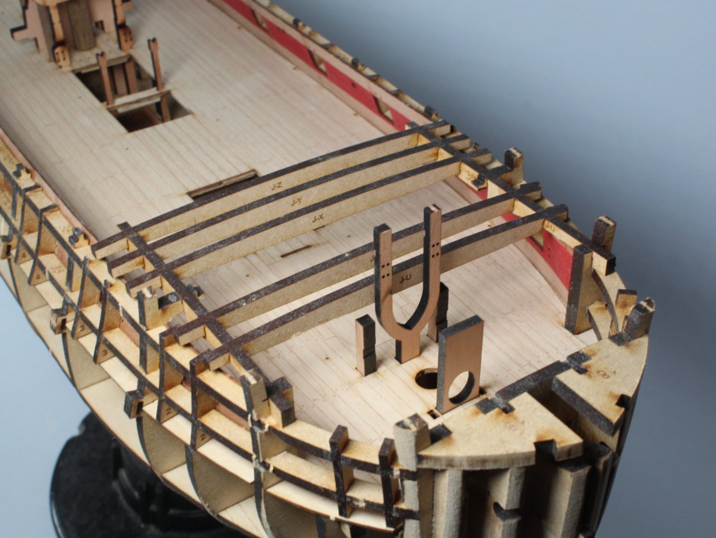
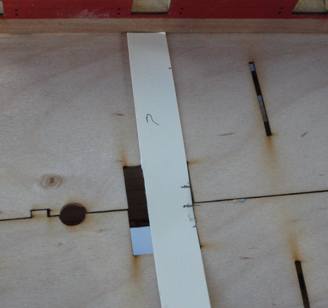
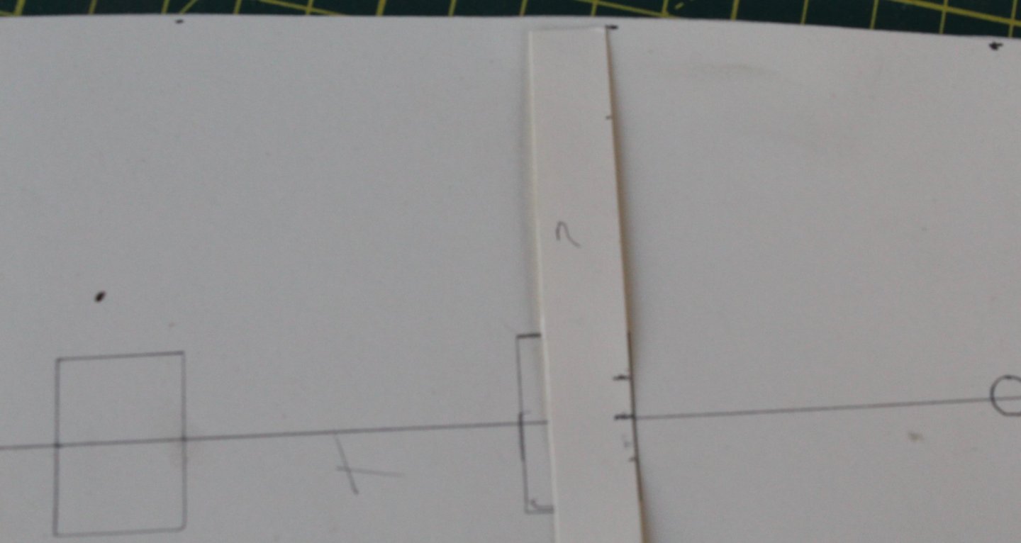
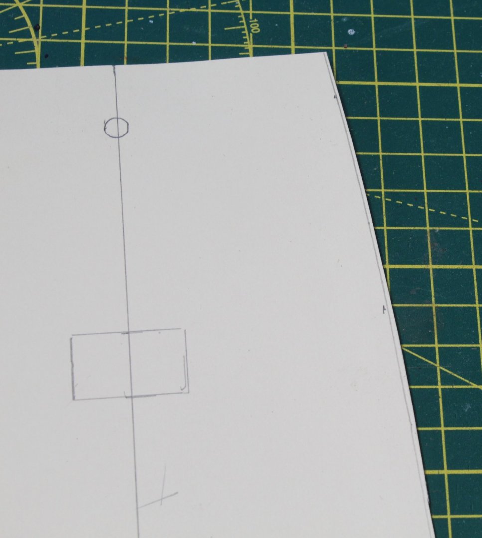
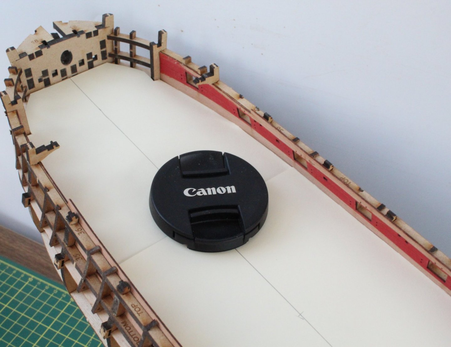
I have now glued the quarterdeck spacer patterns and stern inner bulwarks in place. Compared with my V1 build I have made a much better job of this task this time around, especially with the fitting of the stern inner bulwarks patterns Moving on to fitting the chequer pattern deck I made a template, from a thin cardboard sheet which was trimmed for a good fit. I added a centre line to ensure the template was central across the deck base. I also added to holes for the deck eyebolts for good measure which also ensures good alignment. Using the template the chequer pattern deck was trimmed and was a good fit. The eyebolts are perfectly aligned through both deck part parts. I am also going to use a cardboard template to trim the main gun deck pattern. I used a thin strip to get some data points. The data points were then transferred to the cardboard template, which is an exact copy of the untrimmed deck. Again it is important to use a centre line to ensure the trimming points are correctly transferred to the template. By joining up the dots a trim line is added to the template The template was then trimmed and checked. Due to the size of the gun deck pattern the template will comprise two parts. The first part is a good fit. I would like to say I got it right first time, but the one shown in the picture below was my fifth attempt to get a good fit template. Both templates are a good fit. A close up of the bow template, the camera lens cover was used a point of focus. I think I can now trim the gun deck pattern for a perfect fit.


- 476 replies
-
- 8
-
-
- sphinx
- vanguard models
- (and 1 more)
-
The first task today was to dry fit the inner bulwarks to make sure everything looked OK. I was pleased that everything looked good. Bow Inner Bulwark Stern Inner Bulwark with gun port jig in use. I decide to paint the entire inner bulwark red and walnut for the door. In reality much of this areas will not be visible once the quarterdeck has been fitted. I applied glue to the join areas and then fitted the bow inner bulwarks which was held in place using several clamps. I also brush some diluted pva on the reverse side for good measure. Moving on the adding the quarterdeck spacer patterns. I had a few minor issues with my V1 build when adding the quarterdeck support beams so before gluing the quarterdeck spacer patterns I felt it prudent to dry fit the quarterdeck support beams. I was pleased to see they were all a good fit this time around.
- 476 replies
-
- 7
-
-
- sphinx
- vanguard models
- (and 1 more)
-
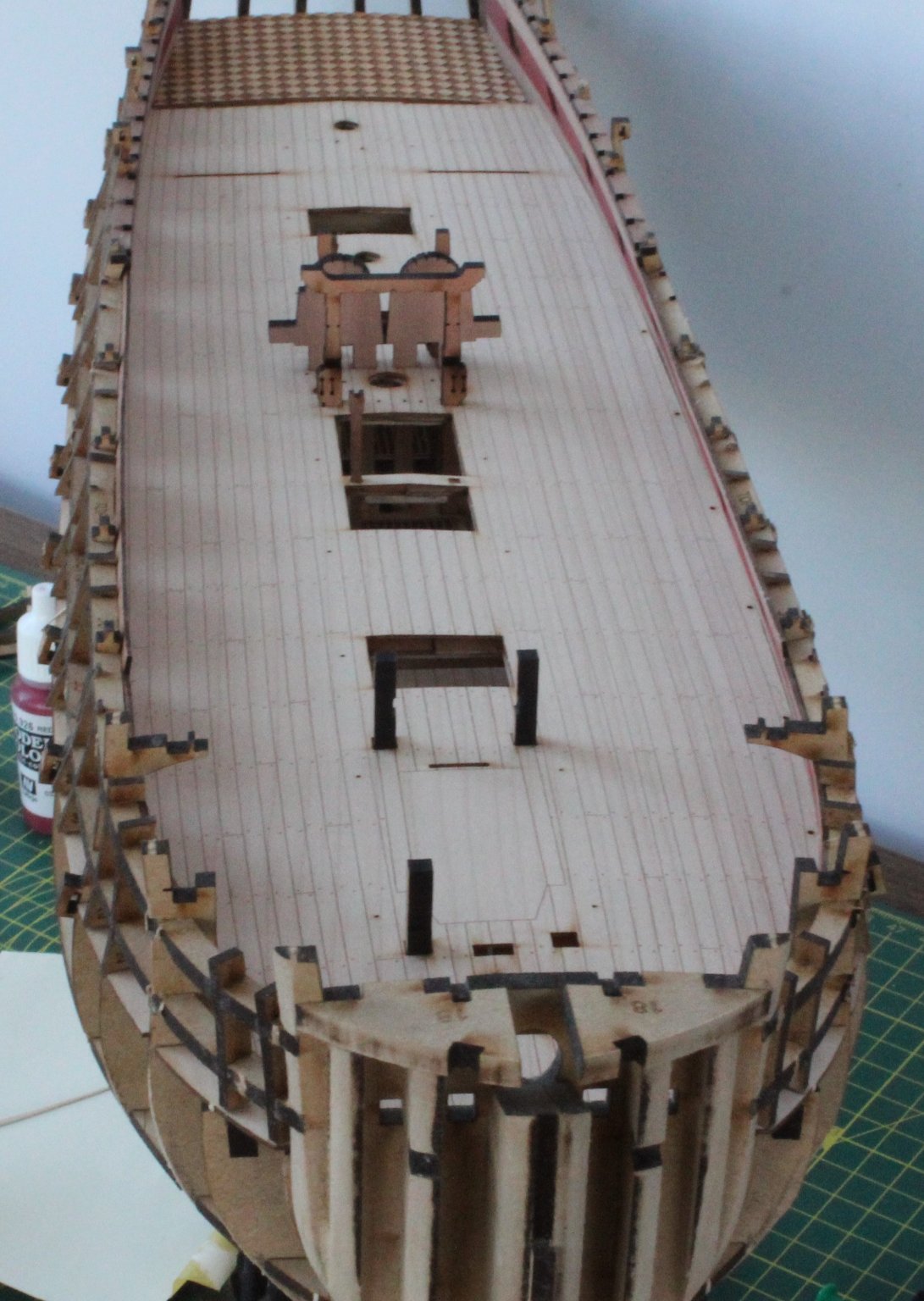
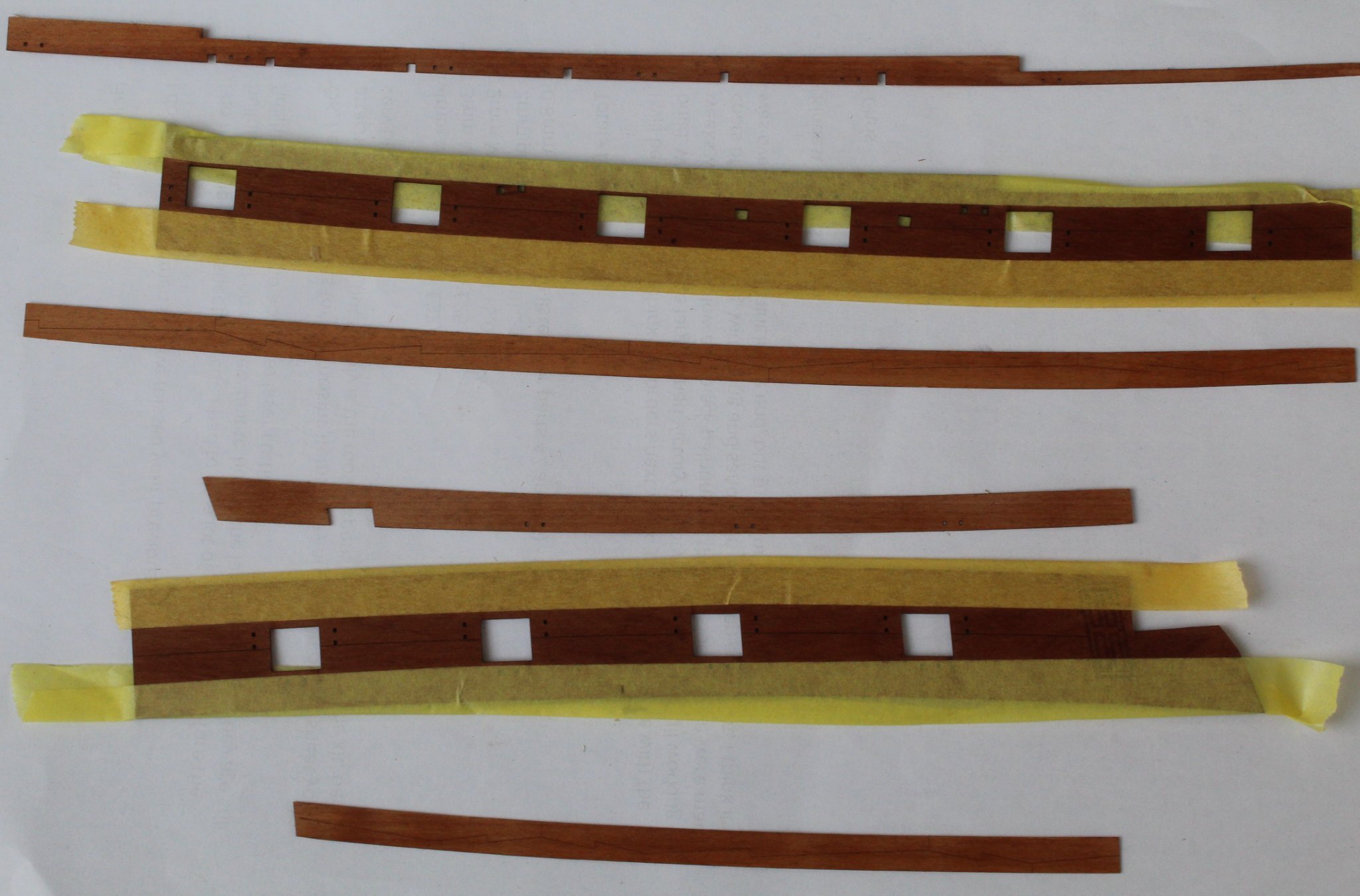
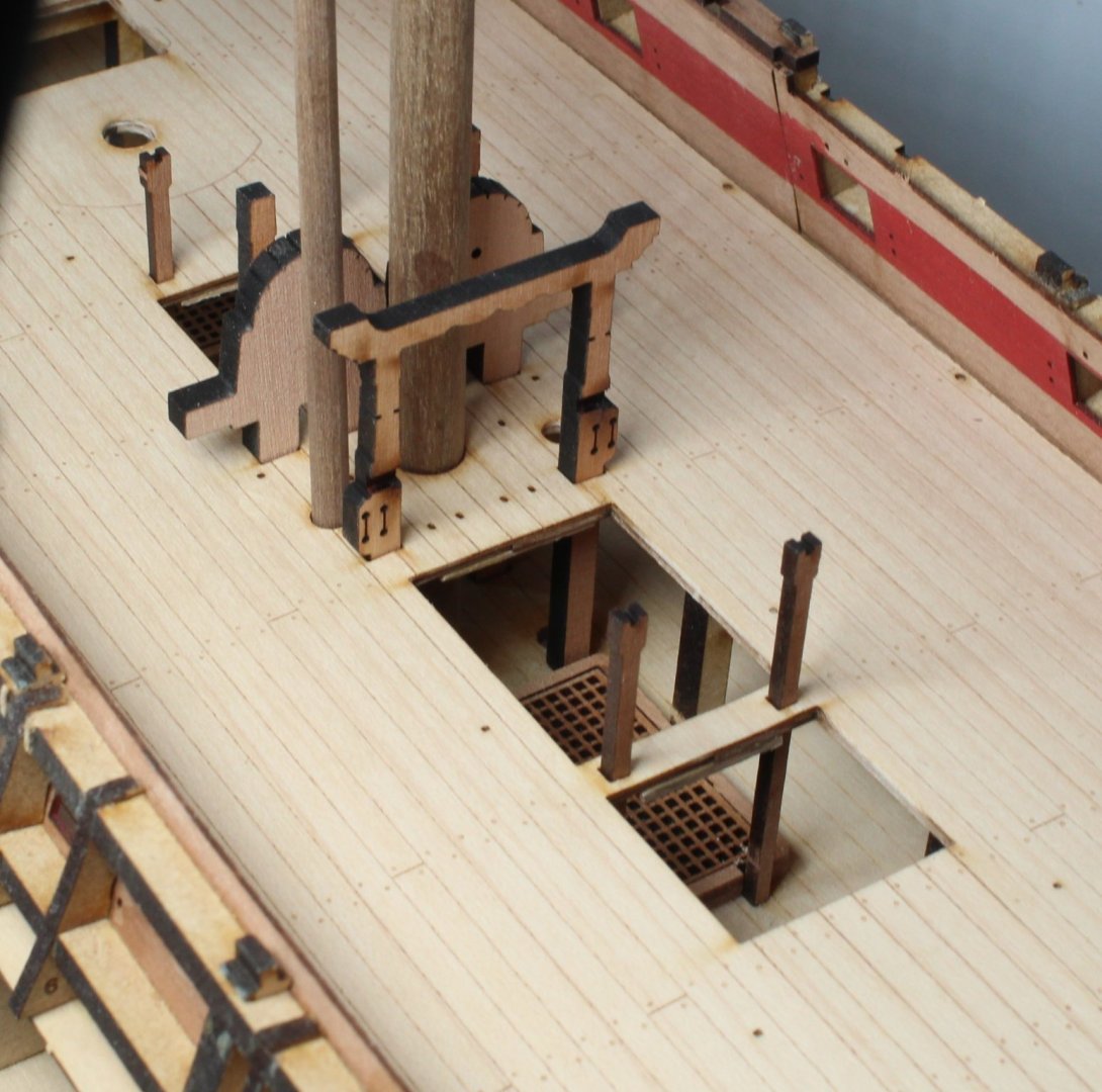
The issue with the bowsprit support not fully engaging in the lower deck locating holes has now been resolved with the removal of some laser char which seemed to be the problem. The bowsprit support is now fully engaged.in the lower deck holes. I have used some spare planking material to add supports to the gun deck joins around the hatches. I did make sure the opening for the other deck items were left unobstructed. Now that I was happy with the fit of the gun deck I went ahead and glued it in place. I used an assortment of objects to hold the deck in place to allow time for the glue to cure. With the deck in place the inner frames were sanded smooth. This is not an easy job, especially around the bow area. There is some remnants of laser char on some bulkheads but it does feel smooth to touch. The bow fillers have been shaped and fitted The stern fillers have been shaped and fitted The inner bulwark, spirketting and deck clamp patterns have been giving a WOP (wipe on poly) coat and will be left for a few hours to allow time for parts to dry. I used tape to mark the positions of the spirketting and deck clamp patterns on the bulwarks so as to avoid adding WOP to the glue areas. Right-hand side patterns after the WOP has been applied. Left-hand side patterns after the WOP has been applied. Once the WOP has dried I will add the flat red paint, remembering to mark off the area after the forward gundeck cabin bulkhead. When I start to fit the inner bulwark patterns I will use a small jig to help ensure the patterns are correctly aligned with the gun port openings so any minor adjustments to the patterns can be made, as necessary.


- 476 replies
-
- 7
-
-
- sphinx
- vanguard models
- (and 1 more)
-
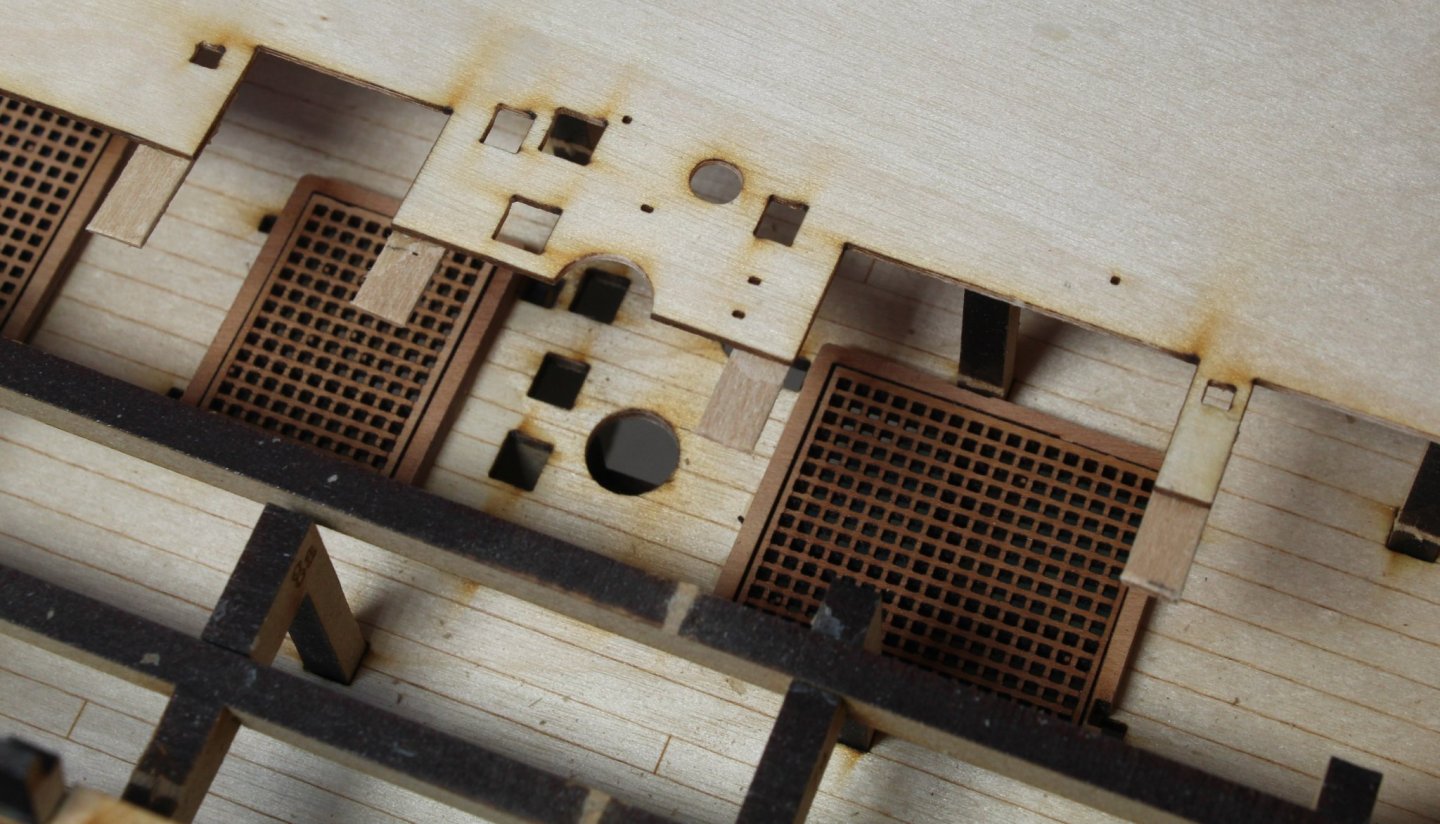
I have faired and glued the stern counter frames and spacer beam this morning. I have also dry fitted the gun deck base, which comes in two parts. As you will note from the above photo I have test fitted the deck items. I think this is an important step to make sure the parts will fit once the gun deck in in place. Everything looks good midships above the deck Everything also looks good below the deck with all the items aligning nicely into the lower deck slots. Moving on to the bow section, again every looks good above the deck However it is a different story below the deck with the bowsprit support which does not locate in the holes provided even after a bit of jiggling. I will remove the gun deck to check the fit and I am sure everything will be fine. I also will add some additional supports to the gun deck before it is glued in place.


- 476 replies
-
- 8
-
-
- sphinx
- vanguard models
- (and 1 more)
-
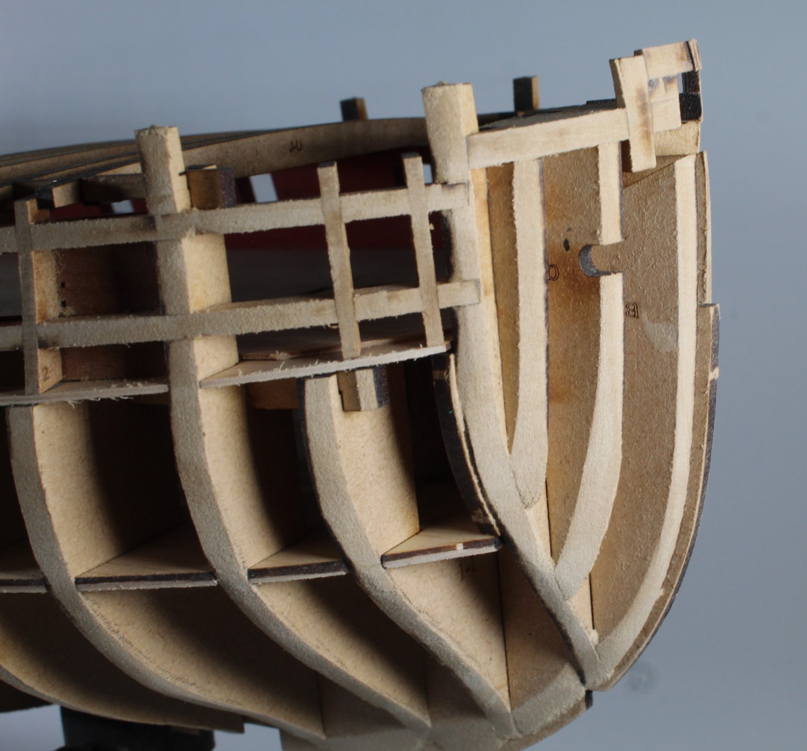
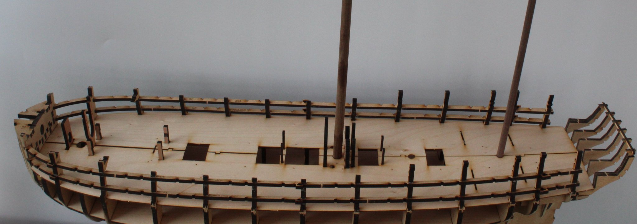
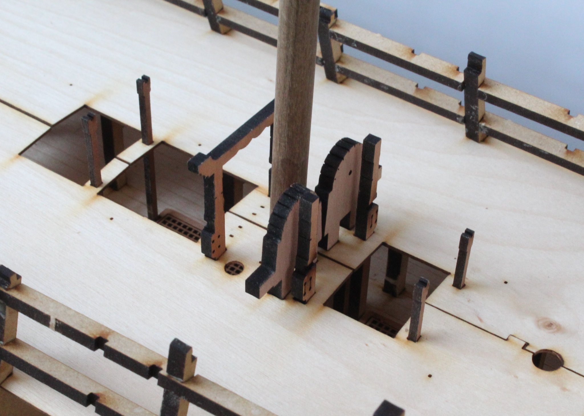
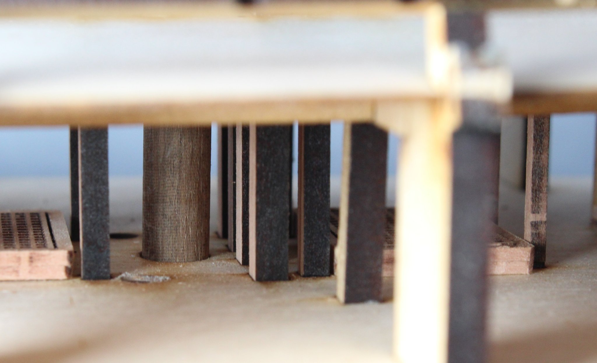
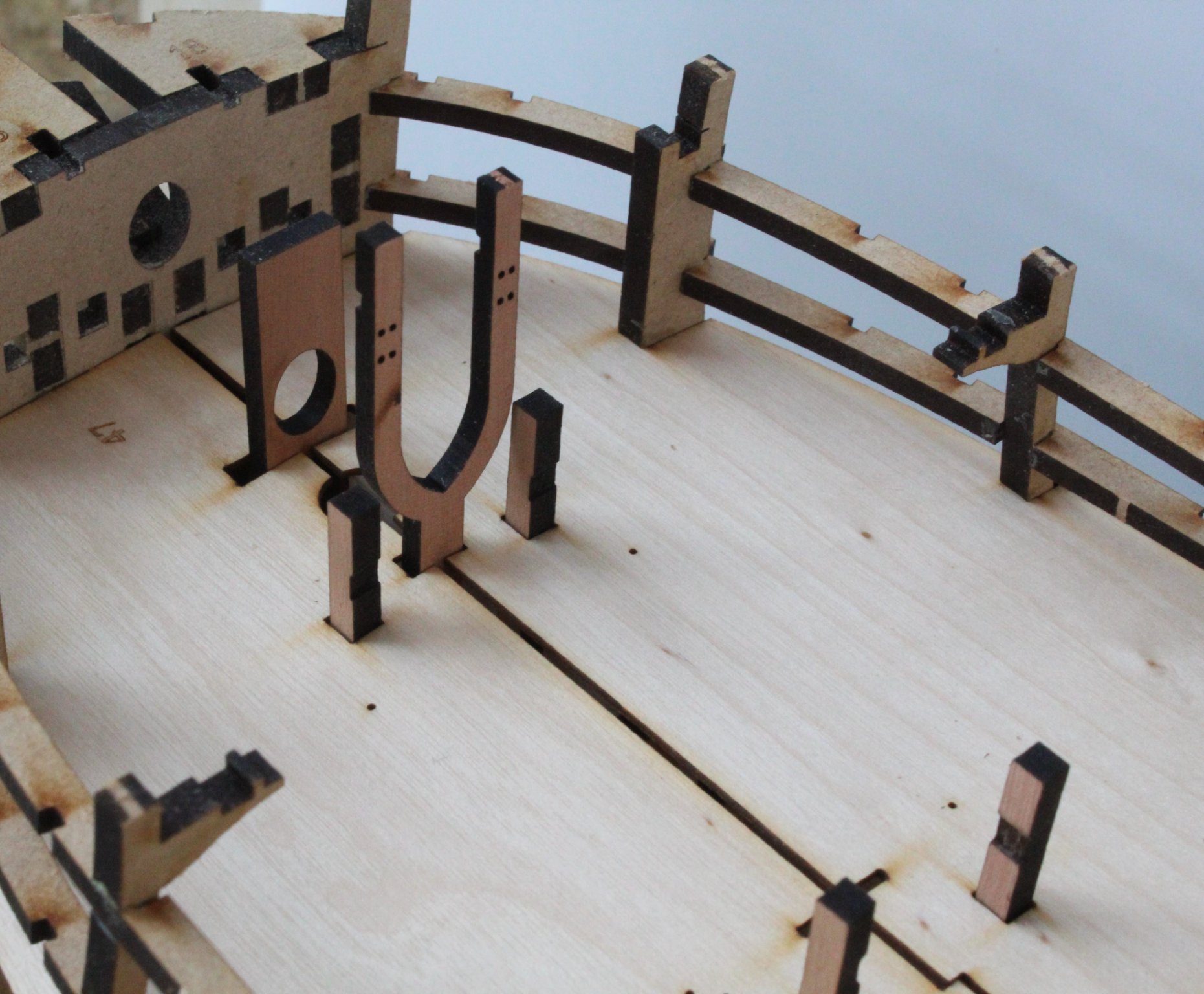
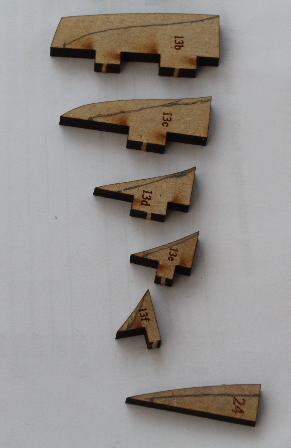
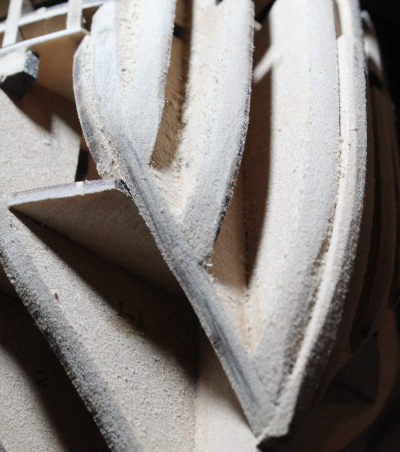
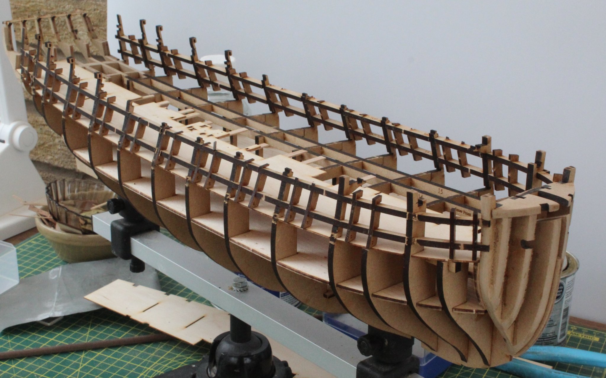
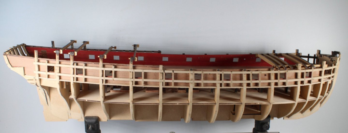
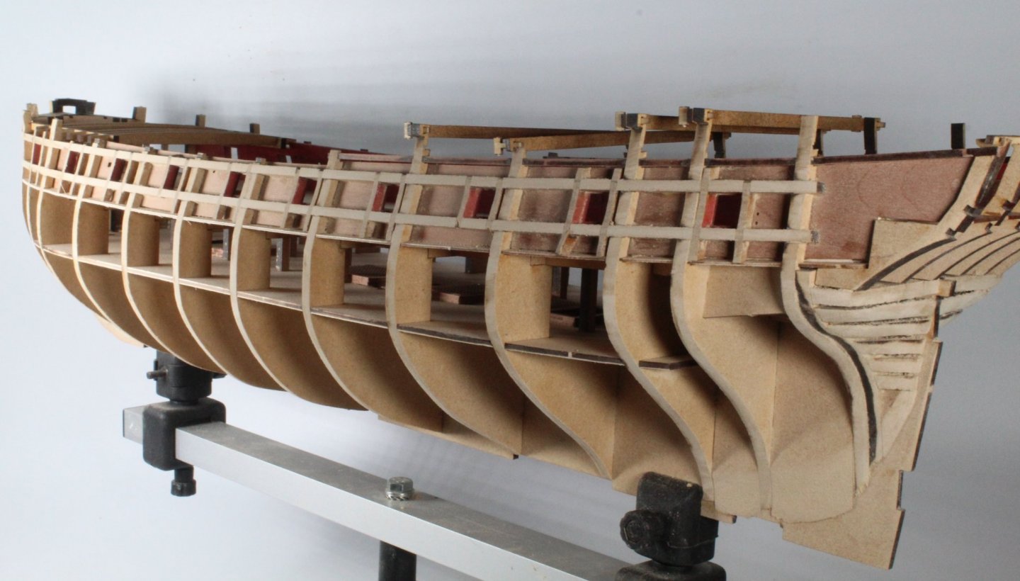
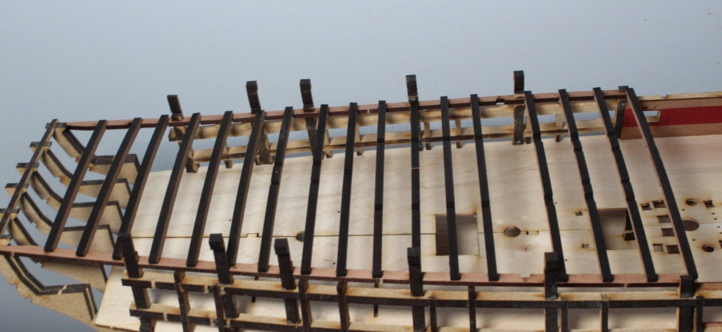
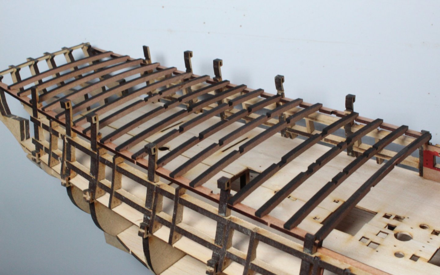
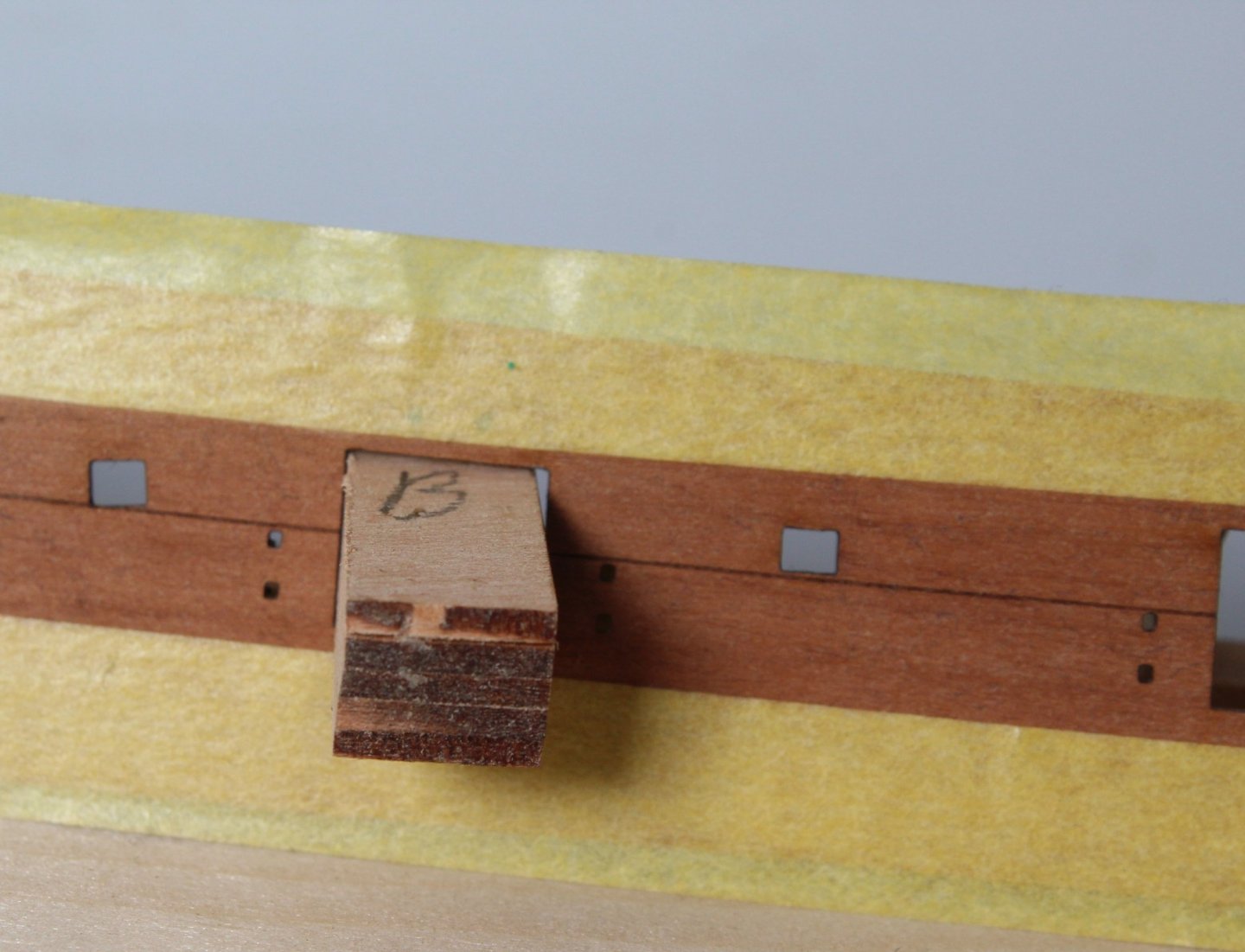
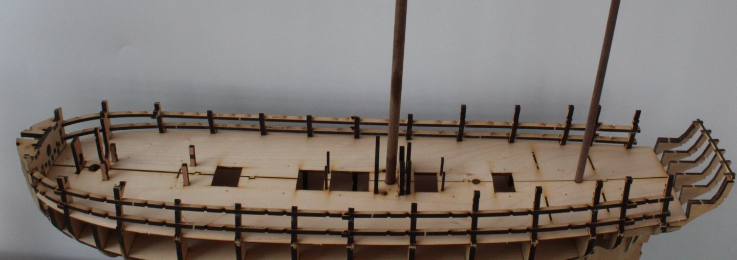
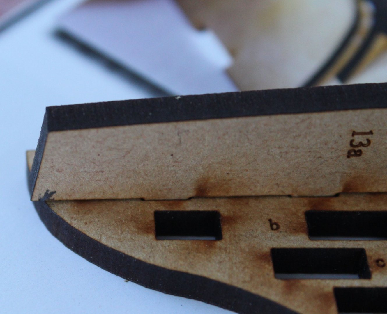
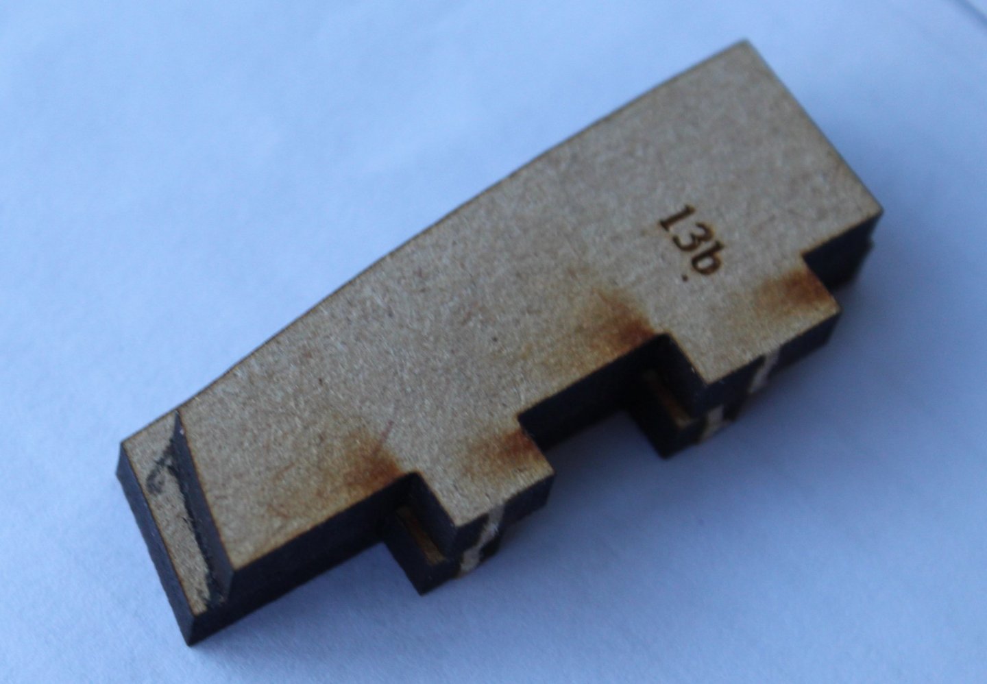
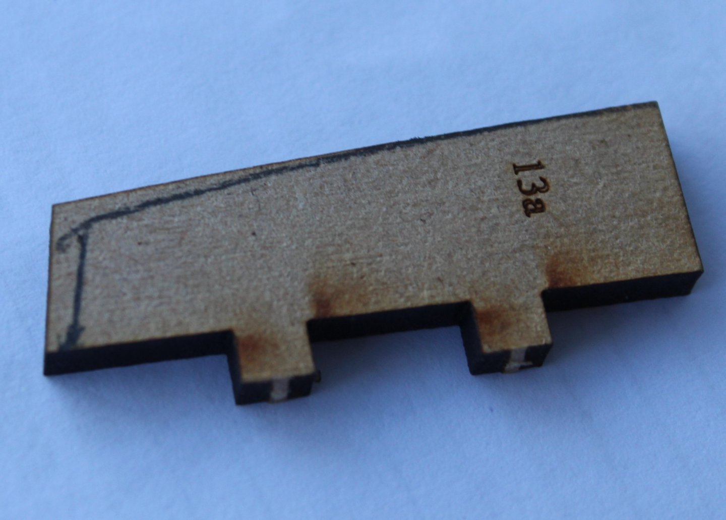
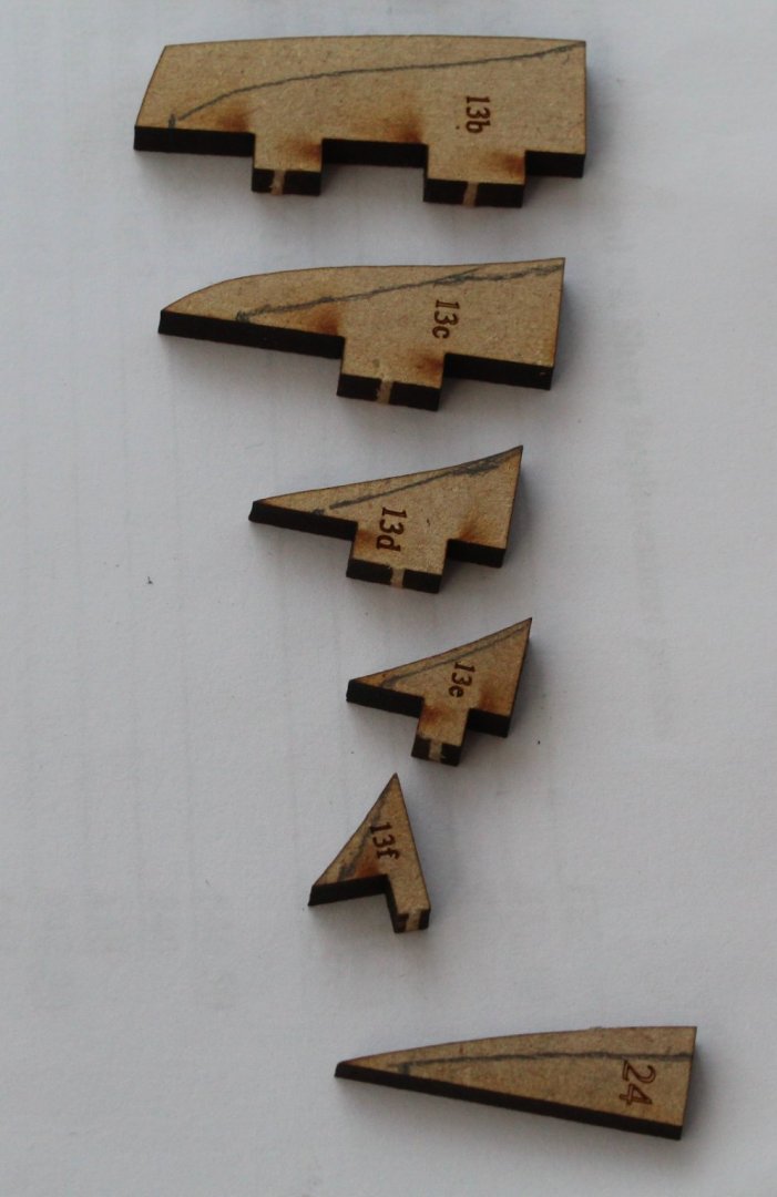
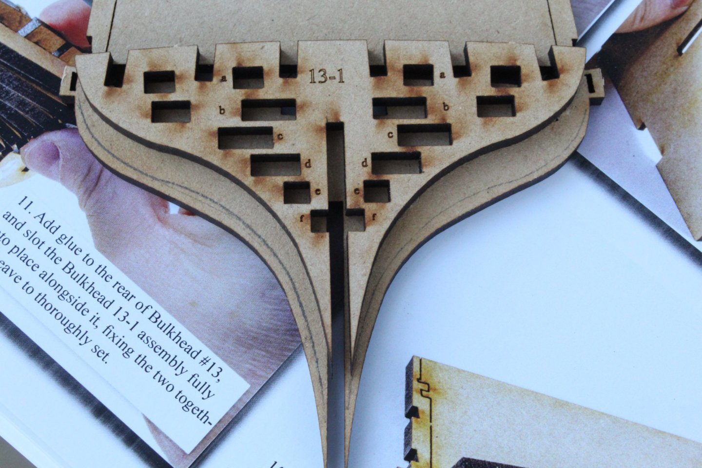
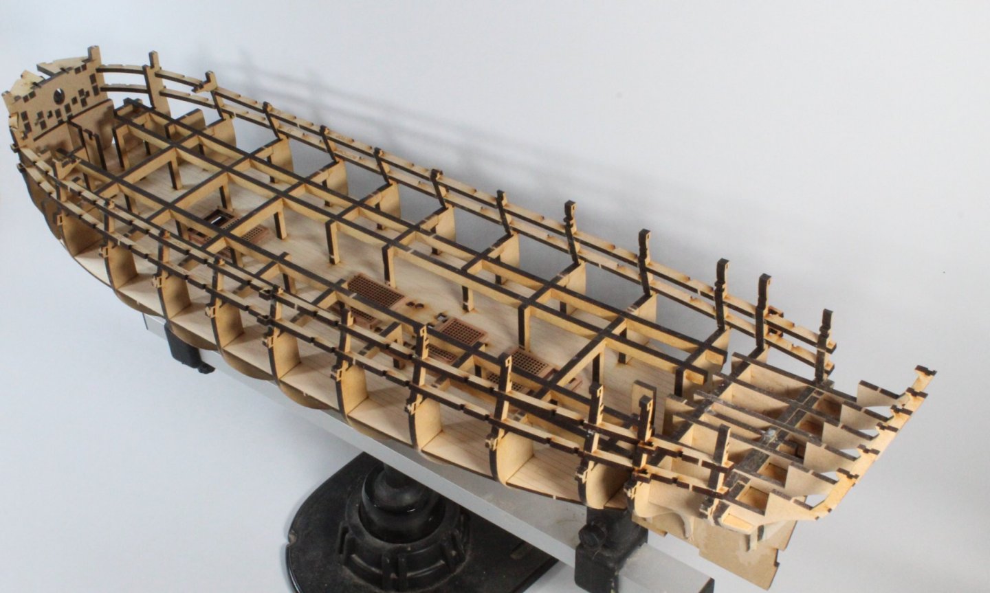
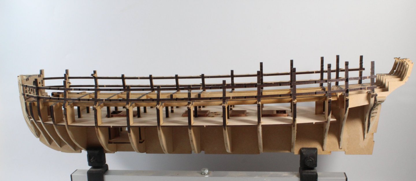
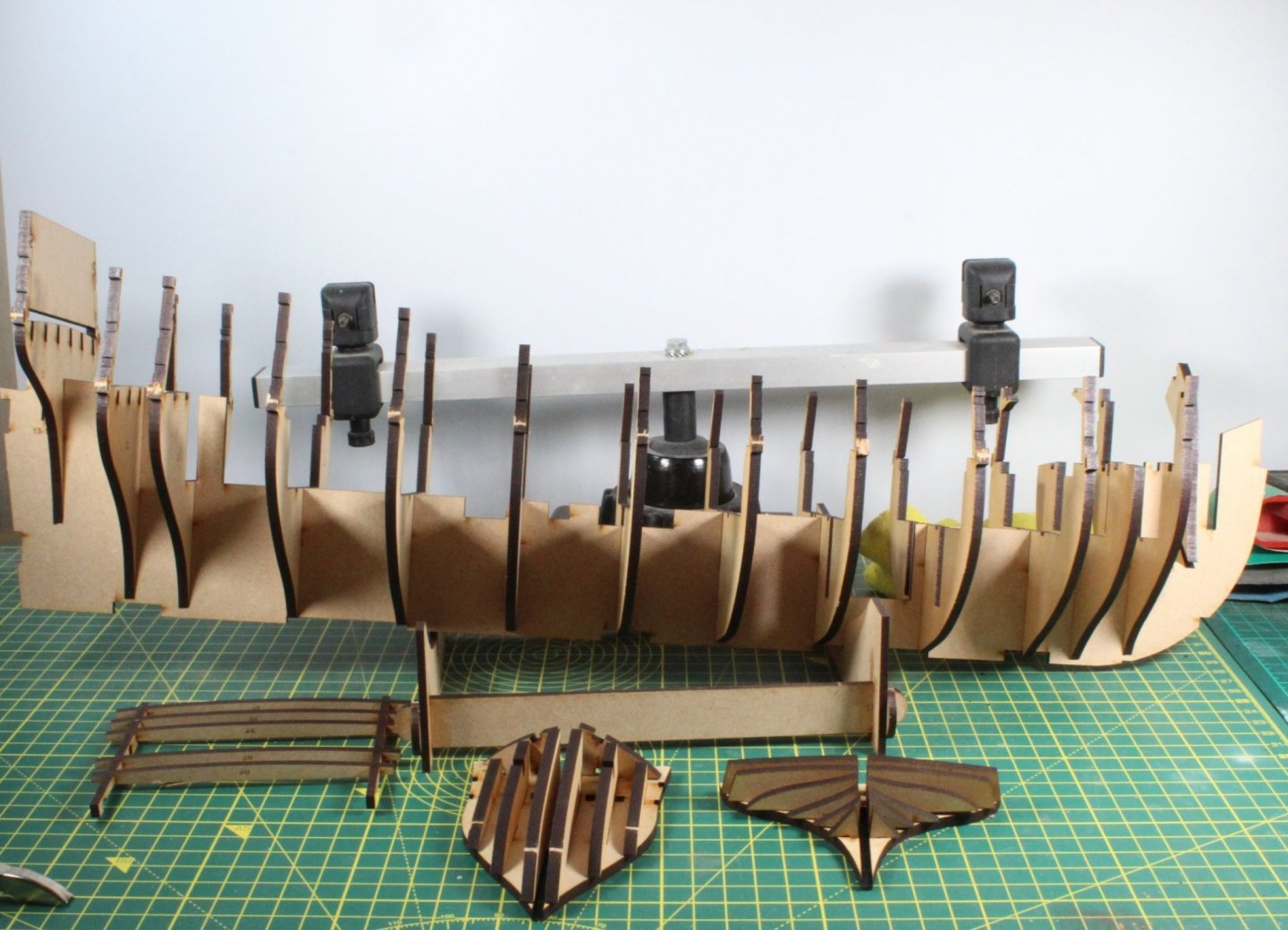
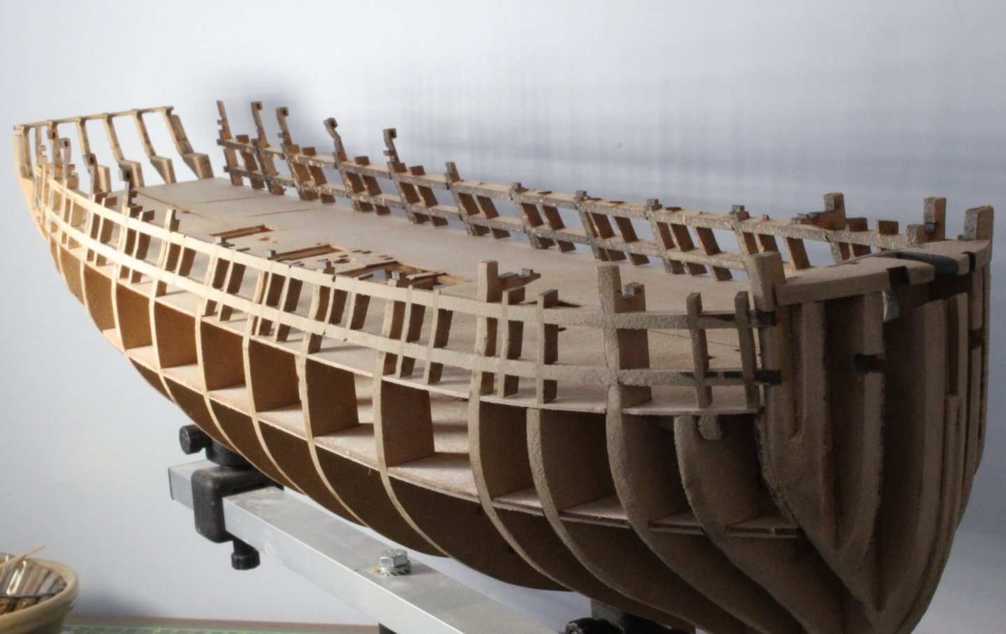
I decided to do a bit more work on my test hull yesterday as I had not faired the left-hand side. Good news the penny has dropped and I believe I now finally understand the flow lines around the bow area as I have been able to get some test planks to lie nice and flat from bulkhead 3 to the stem post, especially in the areas between the gun and lower decks which is my normal problem area. Hopefully this means I will be able to significantly reduce the clinker effect if I can reproduce this on the production V2 hull. With regards to progress I have now reached stage 65 in the build manual with my V2 production build. Starting with the stern bulkhead 13/13.1 assembly I followed the same process as per my V1 build. Starting with the stern filler part 13.1a I marked the edge with the bulkhead, as shown in the photo below. Next I added a line that followed the shape of the stern filler part 13b as shown in the photo below. This provides me with a reasonable guide to fairing this part, much of which I did before it was glued in place. The above process was repeated for the remaining stern filler patterns. I then traced the outline of 13-1 on bulkhead 13 as a fairing guide. Once I had pre faired the parts the parts were all glued in place and then I completed the initial fairing process. I used the bow curve pattern to estimate the pre fairing the bow bulkhead 1 and bow filler patterns 1a, 1b and 1c. I ensured I left a thin laser char edge where the parts were faired. The lower deck and bulkheads were then glued in place. I did test fit the various parts that locate in the lower deck holes, such as the main pump, masts, bitts, etc. The horizontal gun port strips and lower deck coaming were also added. Next the gun deck support beams were added, using clamps to allow the glue time to grip and cure. This is the current stage of the build. The stern counter frames have been dry fitted but they will be removed so the horizontal faces can be faired so they flow with the longitudinal deck beams (build step 72), as I think this a better method than trying to do so with the parts in situ given the restricted access due to the bulkhead ears and gun port strips. I did pre fair the lower parts of the bulkheads before they were fitted, airing on the side of caution.

- 476 replies
-
- 8
-
-
- sphinx
- vanguard models
- (and 1 more)
-
True, as the bow filler pieces are curved top to bottom but I would think you would apply a similar fairing angle to the each bow filler piece, maybe that is where I am going wrong.
- 476 replies
-
- 1
-
-
- sphinx
- vanguard models
- (and 1 more)
-
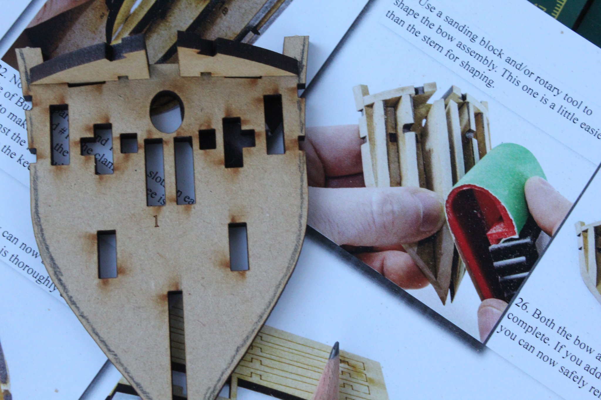
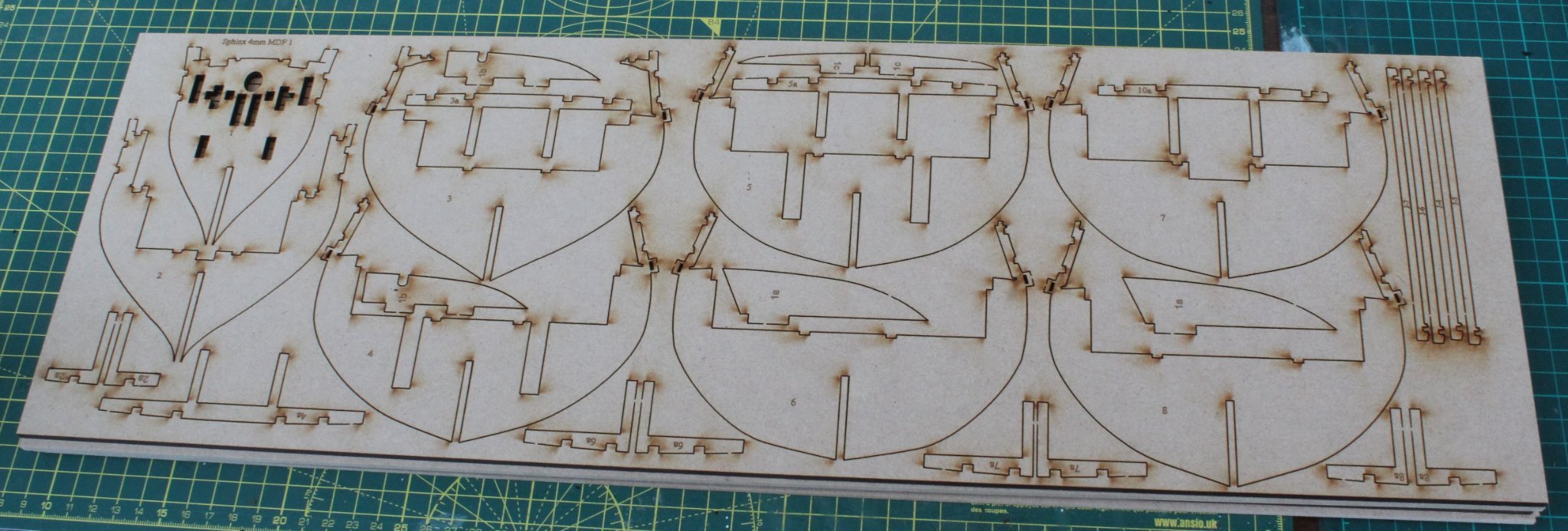
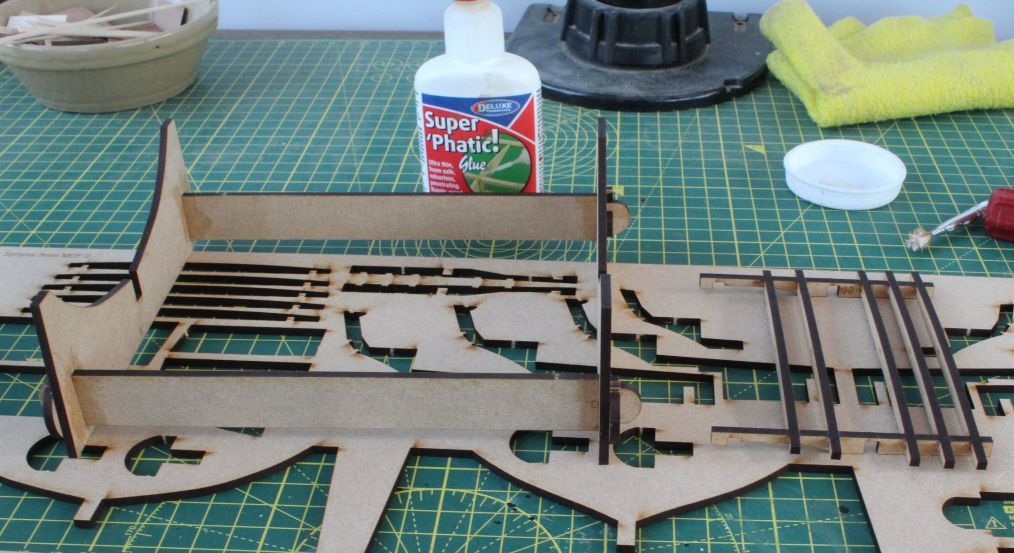
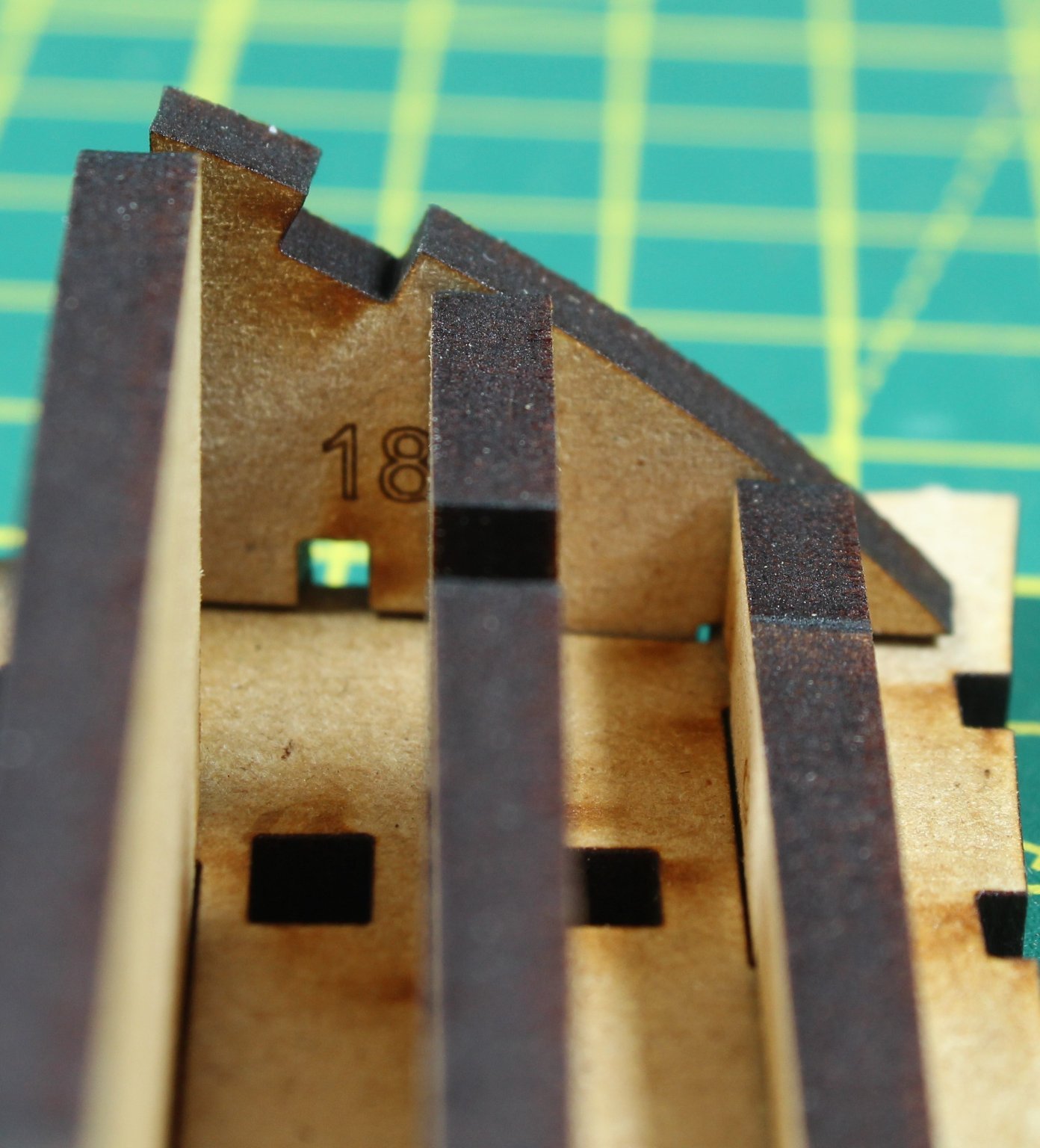
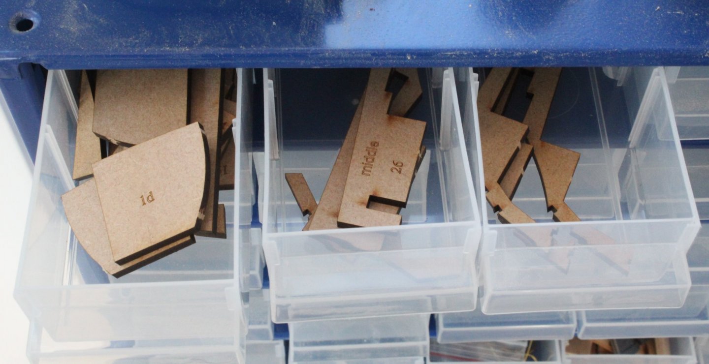
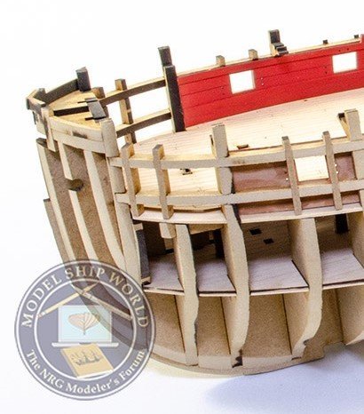
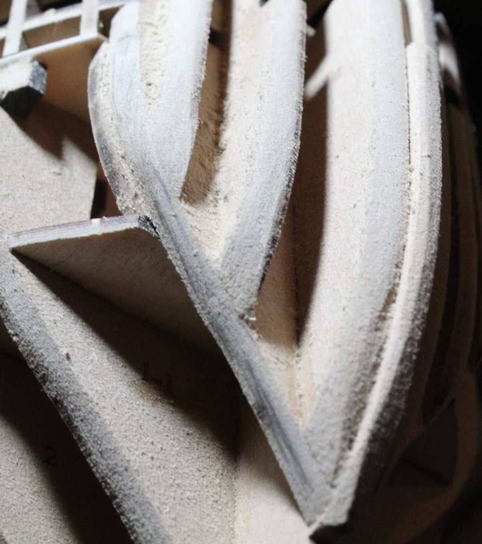
I did a quick test this morning and added some balsawood fillers to the bow bulkhead 1 assembly on my test hull. I did not not spend a great deal of time but did enough to get a nice flow of a plank across the bow bulkheads. I have also noted the gun deck support pattern (part 1d) were sanded during the fairing process on the test hull which is not necessary. I have covered later on in this post. I have now decided I have spent enough time messing around with my test hull and now is the time to put my big boy pants on and make a start with the V2 production build. The first task I undertook was to sort through the various wood sheets and group them in the same order as the first 6 plan sheets, inserting each wood group in the fold of their associated plans sheet. I also made a list cross referencing the wooden sheets with the plan sheets, which will help me locate parts more easily. Starting with plan sheet 1 I placed the 2 x 4mm MDF and 2 x 3mm MDF sheets on to my workbench. Starting with 3mm MDF sheet 1 all the parts were removed. The cradle and bow jig were assembled using Super Phatic glue. The other parts on the 3mm MDF sheet 1 were placed in to storage so they will be ready for action later on in the build process. I then removed all the parts from the other 3 MDF sheets and dry fitted the various bulkheads to the keel. All other parts, such as the filler patterns, deck supports and stern counter frames were placed in storage draws. As per my previous post I was not happy with how the planks were laying across the bulkhead 1 assembly. I think the bow curve pattern (part 18) gives a good indication of required fairing angle required for the bow frame patterns. I have also taken onboard comments and advice to keep a small amount of laser char on the back edge of bulkheads and to not overthink the fairing process. When looking at the bow filler patterns 1b and 1c in relation to the bow curve pattern it is clear the back edge is not in line, as can be seen below. When looking the prototype photo in Jim's build log the laser char is left on the back edges of bow filler 1b and 1c which are not level with the bow curve pattern, as shown below. I am pleased I have noticed now and means leaving an edge of laser char is the right way to go. When looking at the prototype after the fairing process it would appear the bow curve pattern has been sanded so the back edge of the bow fillers 1b and 1c are now flush. I have also noted that there is no need to fair the edge of gun deck support patterns (1d) which I did fair on the test hull.


- 476 replies
-
- 6
-
-
- sphinx
- vanguard models
- (and 1 more)
-
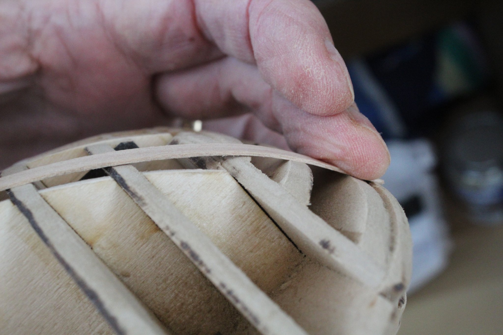
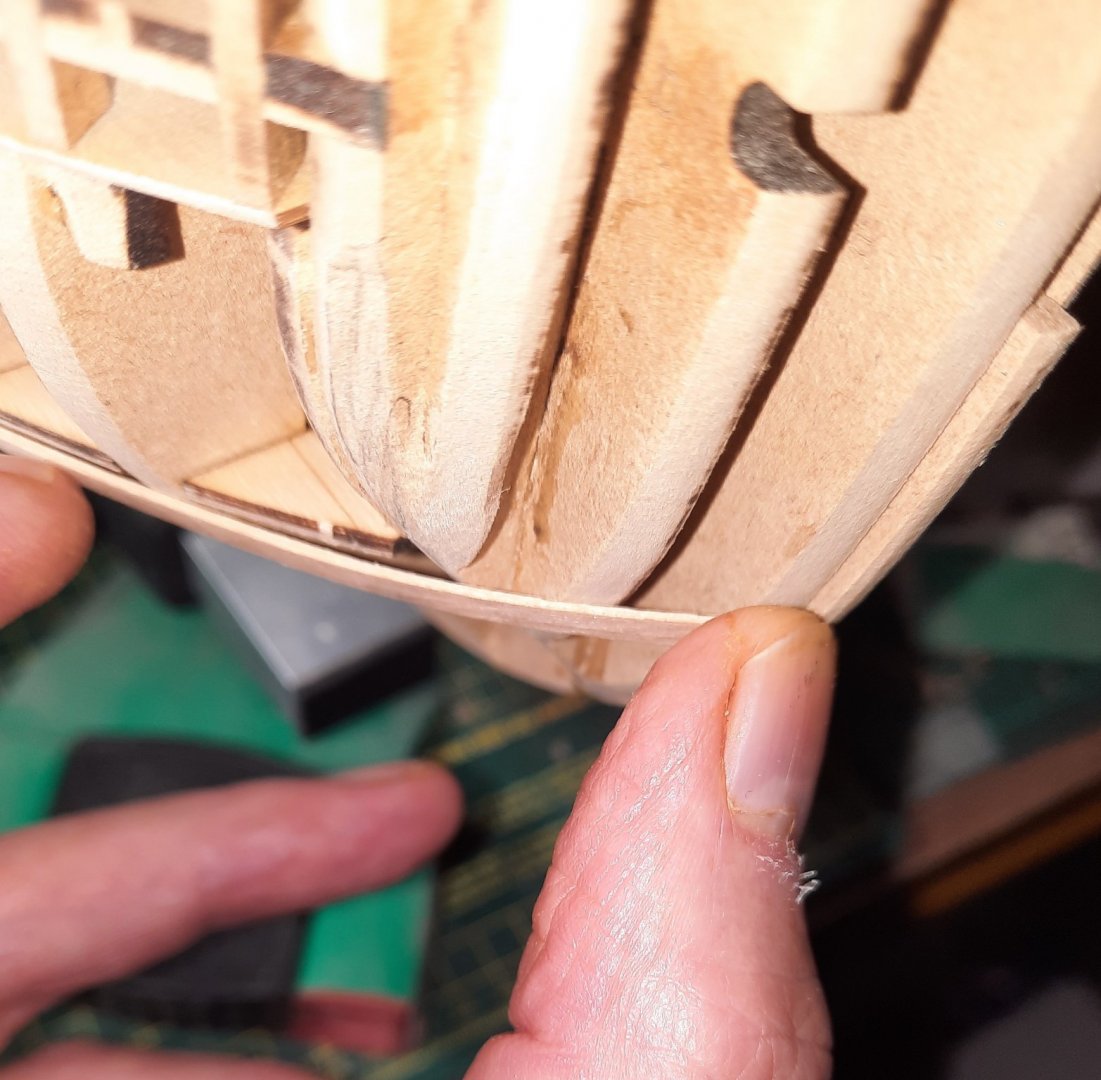
@glbarlow when fairing the bow section I used the curve of the top piece as a guide When I fit plank lower down there is a big gap as can be seen below, so maybe the 2nd bulkhead needs a sharper angle.

- 476 replies
-
- 3
-
-
- sphinx
- vanguard models
- (and 1 more)
-
@chris watton and @James H. I did not order the inner bulwarks sheets as spares hence the reason why they are not fitted on the test hull. Yes the stern does require more fairing as I indicated in my post. I was not sure if I need to follow the flow of the lower deck so asked the question before progressing with fairing the stern area further. I am much more concerned about the clicking effect with the bow area as it stands. Tomorrow I may fit some balsa fillers to see if I can workout how to avoid the clicking of the bow planks.
- 476 replies
-
- 1
-
-
- sphinx
- vanguard models
- (and 1 more)
-
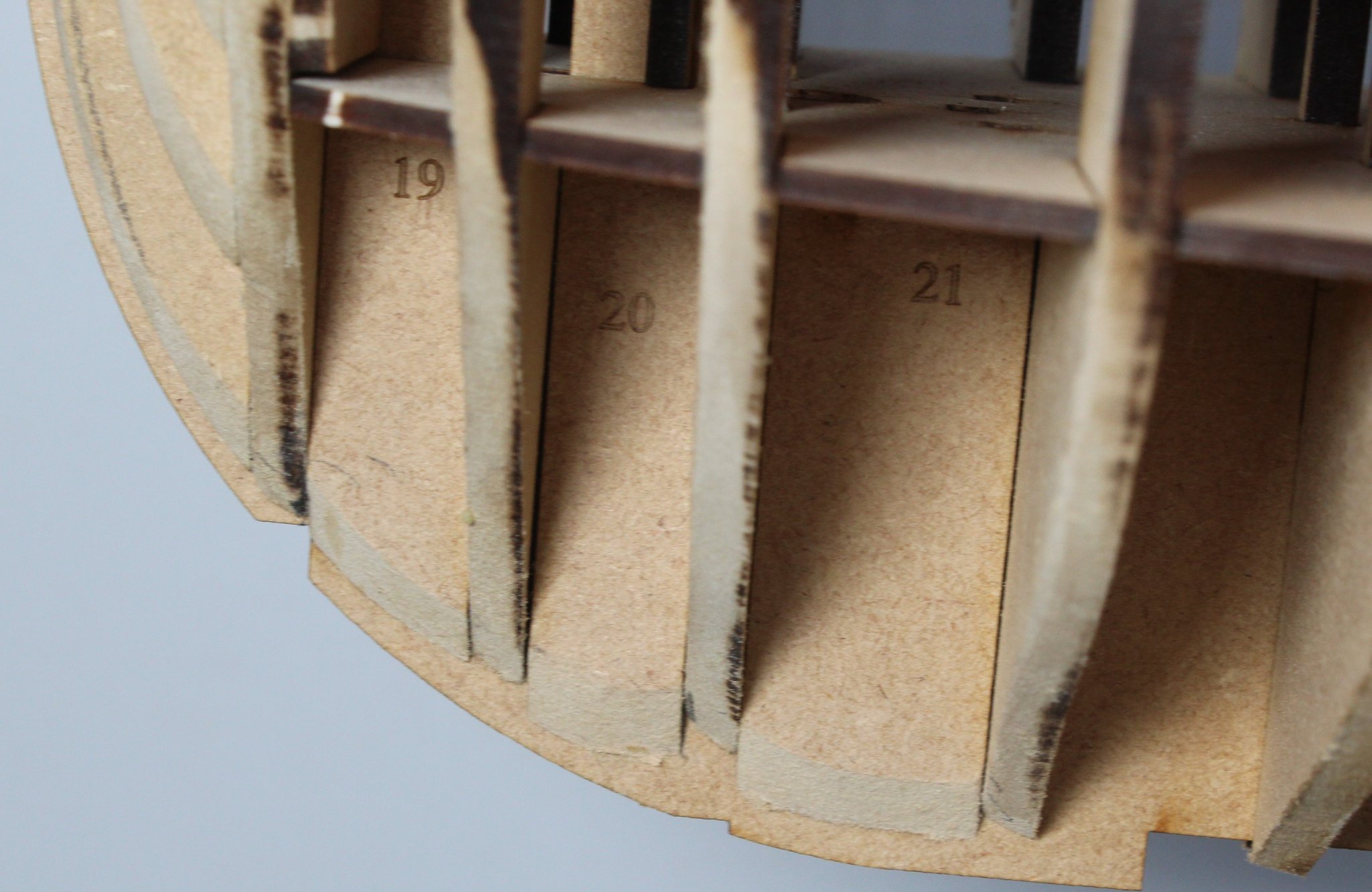
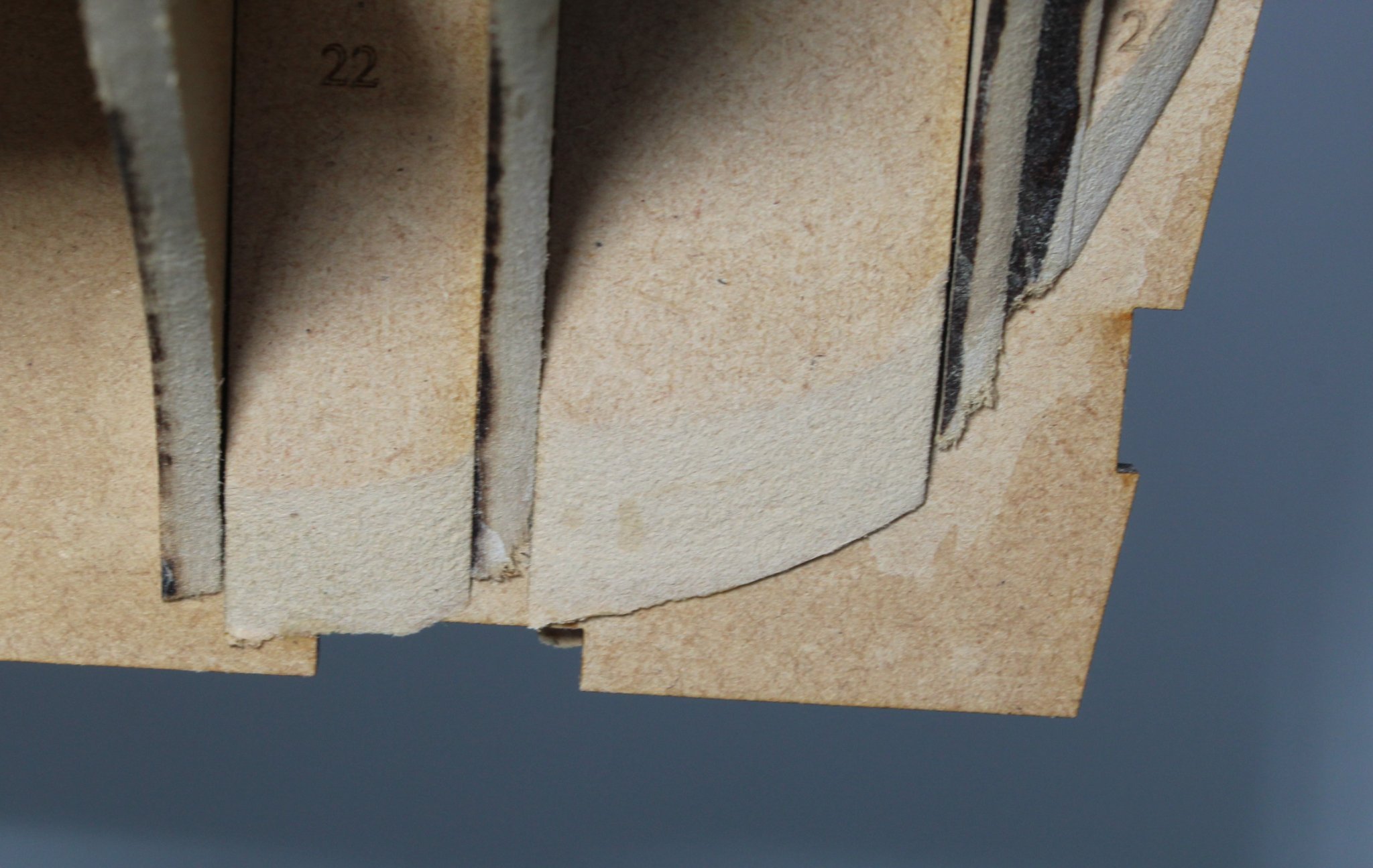
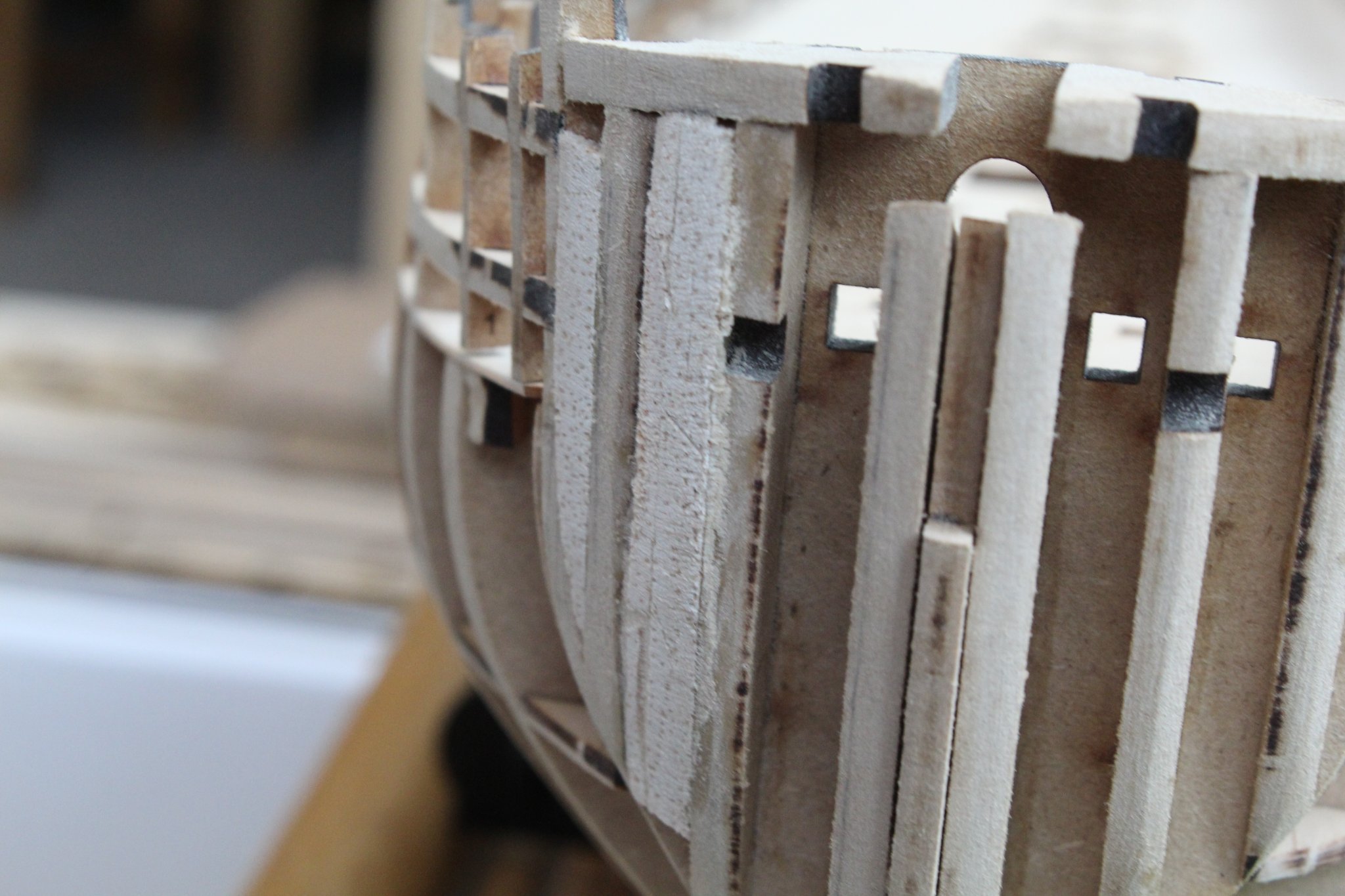
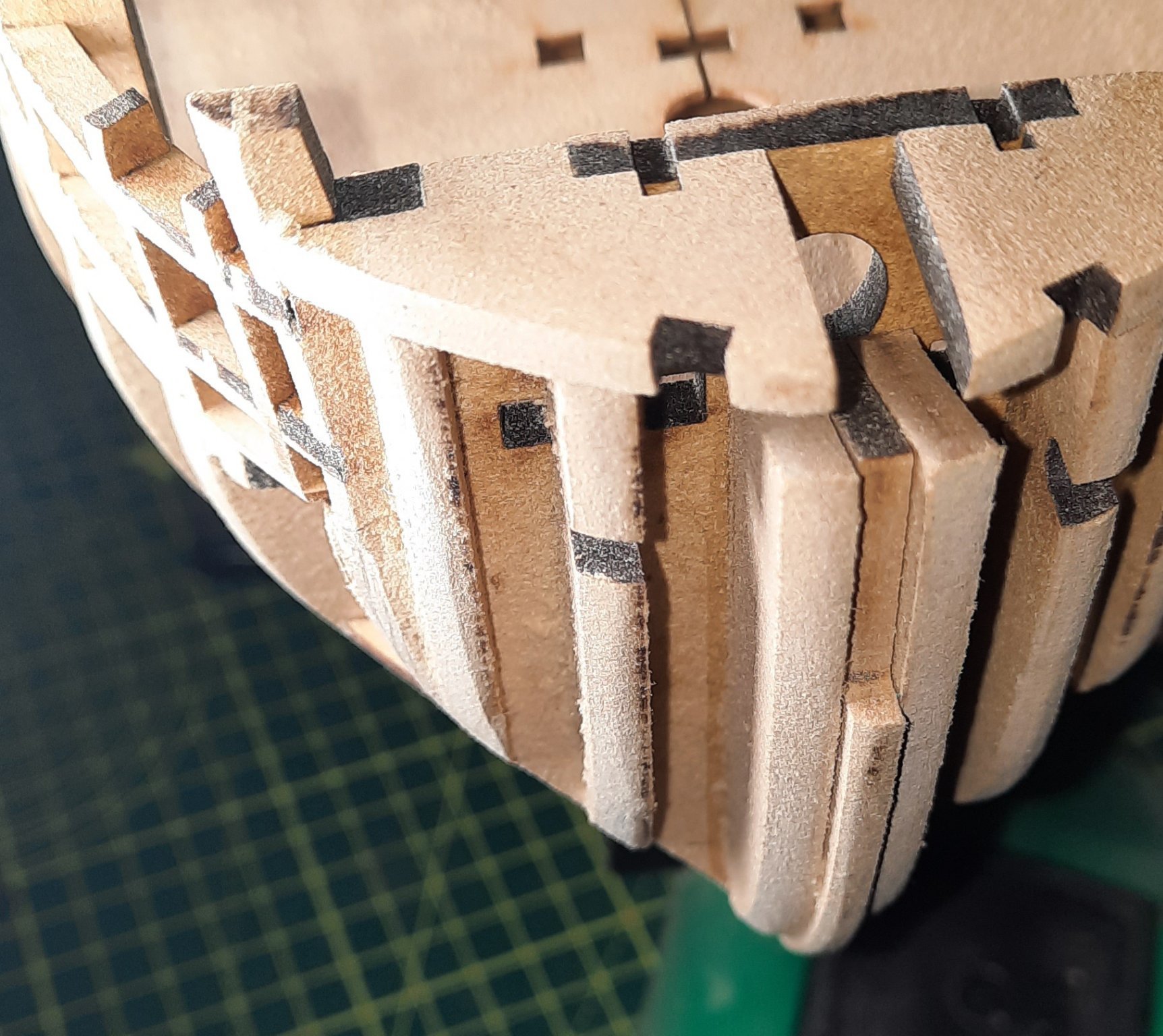
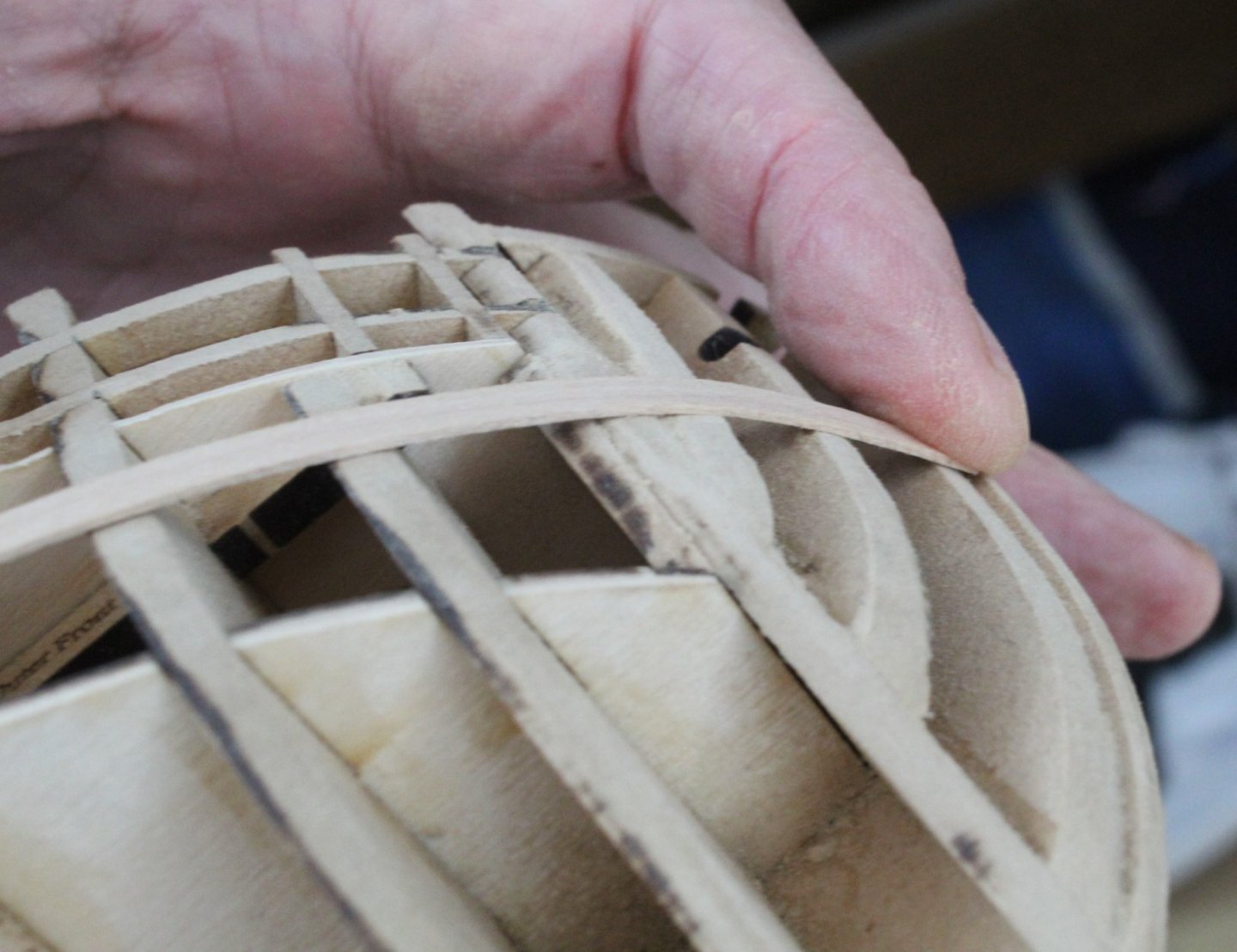
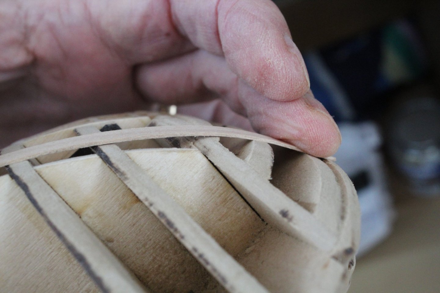
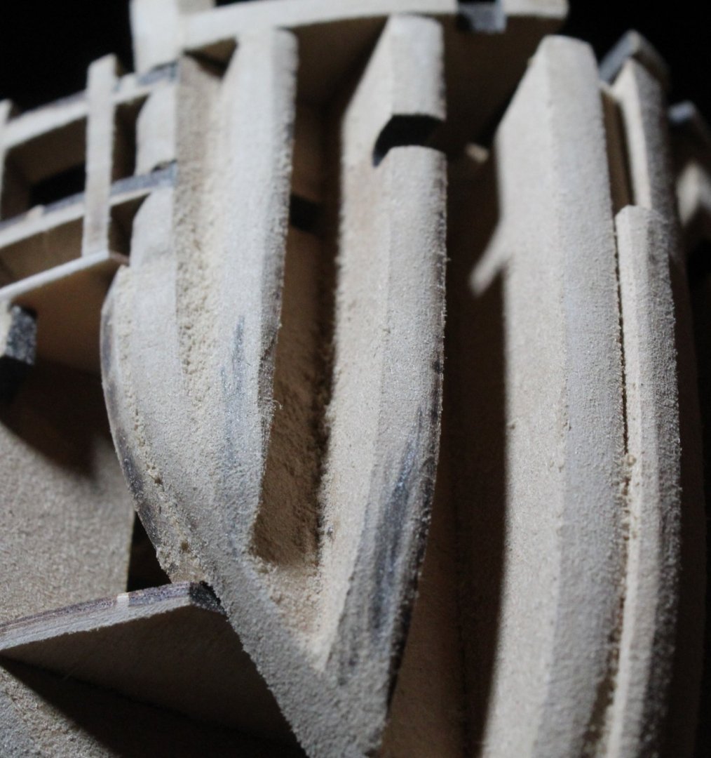
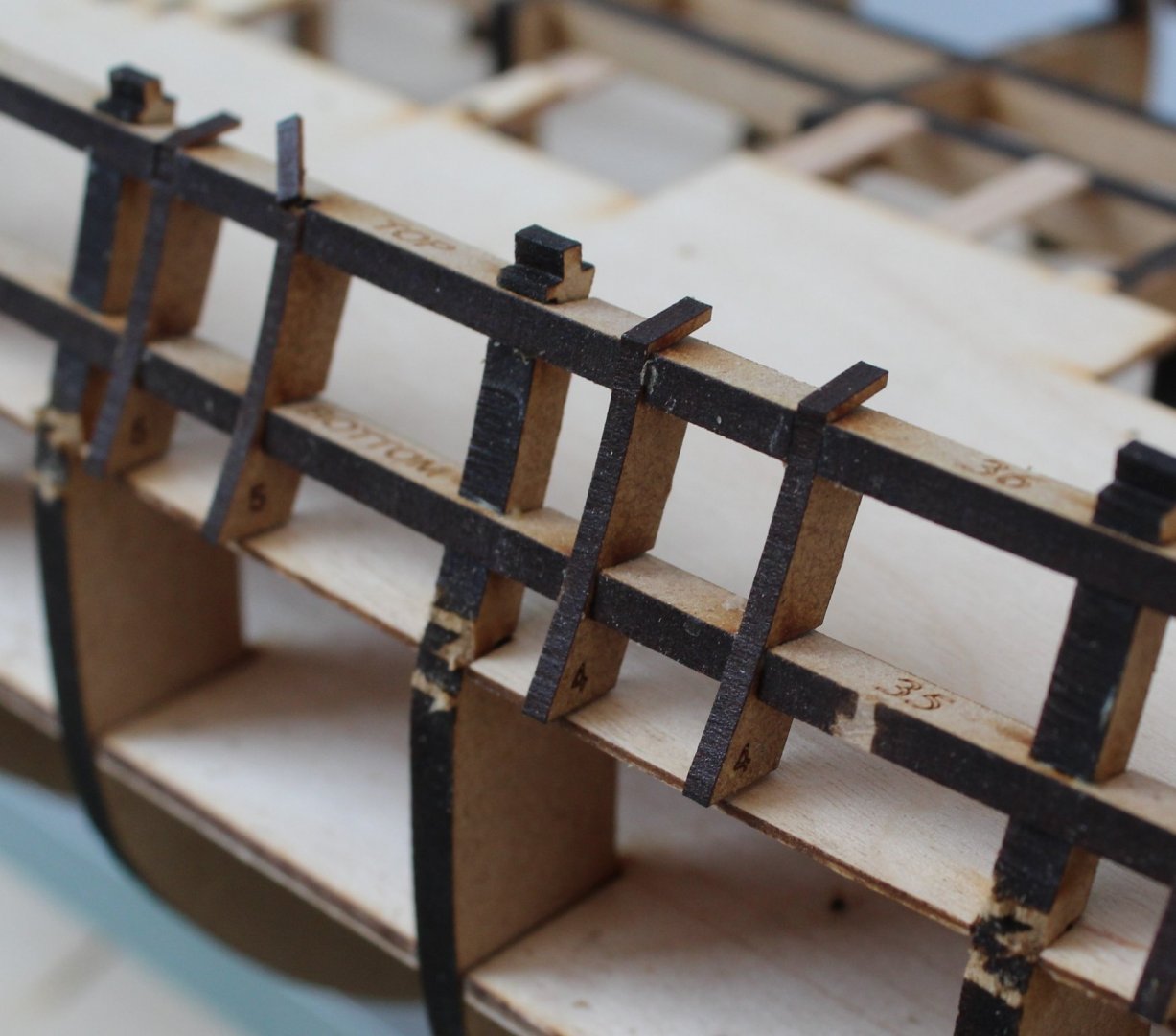
I need help and advice please with regards to fairing. I am about 90% through fairing the right-hand side of my test hull and I have a couple of questions and would really appreciate some help and advice. As can be seen in the first photo the laser char has been removed. There is still a bit to remove at the stern end, which is not visible in the photo The first question is regards to fairing the stern area. Should I just remove the laser char and follow the same curve of gun port strips or should I be more aggressive lower down the bulkheads and follow the shape of the lower deck, i.e. in the photo below should I sand the bulkheads flat to follow the deck edge? The second question is regarding the fairing around the bow area. When I try a test plank, as shown below it looks like a reasonable fit across the bow bulkheads However when I move the plank toward the keel the plank does not lay flat across all the bulkheads, it is raised above the third from left bulkhead. This will result in clinker planks The question is therefore do I sand the two leading bulkheads as indicated by the pencil marks in the first photo below, or do I add a thin strip on the pencil mark shown on the second photo below? Sand the pencil marks? Add a filler strip to pencil mark? Please help if at all possible, thanks in advance
- 476 replies
-
- 4
-
-
- sphinx
- vanguard models
- (and 1 more)
-
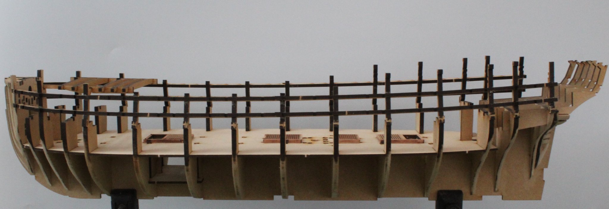
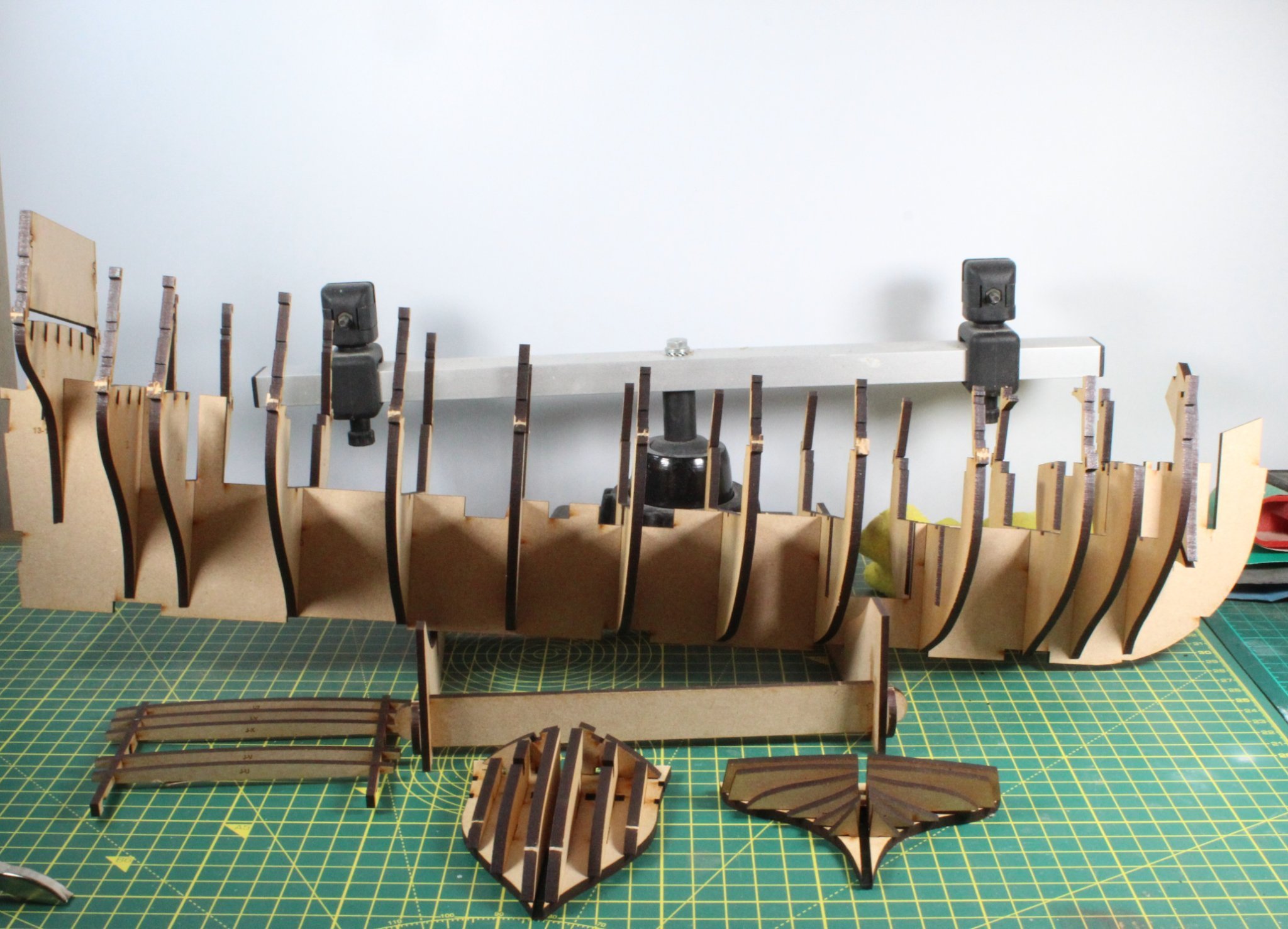
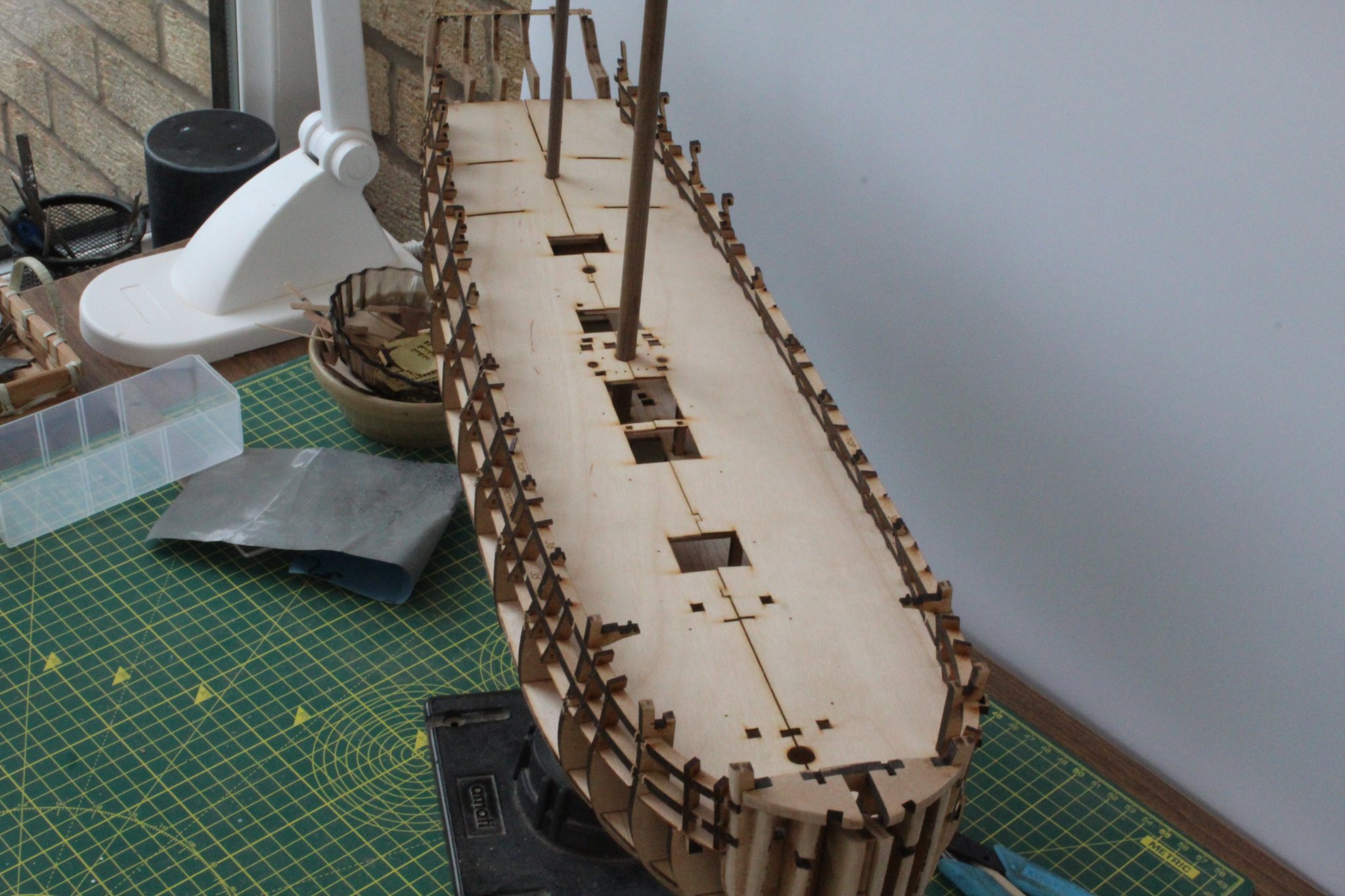
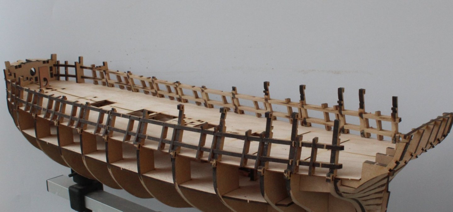
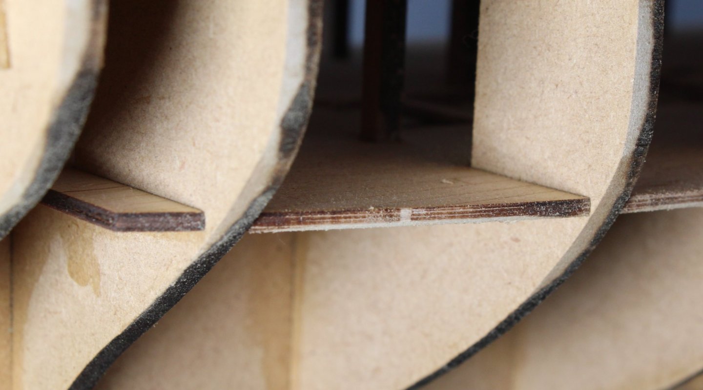
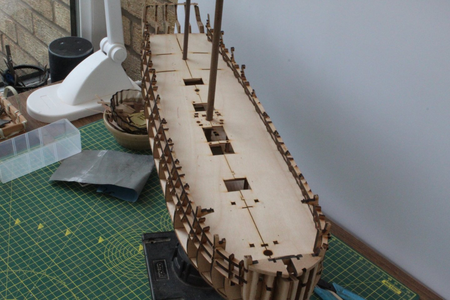
Time for a quick update. I am still working on my test hull and I plan to start work on the production build in the next few days. Although not strictly necessary I think buying the spare sheets and building this test hull has been well worth the time and expense so far. After dry fitting many of the hull items I reached a point where I feel I understand the design much better and how all the parts should fit together. It has also made me appreciate even more what a brilliant job @chris watton is doing with all his designs. During this process I have realised where my V1 started to go wrong as I had not taken the time or care to check if some of the parts were correctly seated during this early part of the build process.. Another reason for building a test hull is to overcome the biggest problem I have had with all my previous builds which is is getting the hull properly faired. I lay test planks which appear to make good contact with the faired bulkhead edges but I always end up with "clinker planks" around the bow, even when I have used Chuck's lateral bending methods which proves I have not faired the hull correctly. I plan to fair my test hull and to check some planking runs to see if I can understand why I have this problem and to hopefully produce a hull that is clinker free. The picture below shows my test hull after the gun port patterns have been fitted and glued in place. I opted to add undiluted pva (titebond) glue to the both the longitudinal and vertical gun port patterns slots rather than using a diluted pva solution after the parts were fitted. I used super phatic glue for the bulkheads and deck assembly which was easy to brush in and flowed nicely into all the joint areas. One of the concerns I had with the V1 build was the lack of support under the deck in certain places. I have therefore added a few short strips in these areas, as shown in the next couple of photos. After the 2nd part of the deck was fitted I was pleased with the additional support the strips provided so this is something I will add to the V2 production build. As part of the testing phase I felt it prudent to check the fitting of the mast dowels. I removed the laser char from the mask holes and hatches on the deck parts before they were fitted. On the production hull I will also double check all the openings for the other parts (bitts, main pump parts, etc)


- 476 replies
-
- 8
-
-
- sphinx
- vanguard models
- (and 1 more)
-
I am just experimenting with painting techniques using a redundant cradle. I will build the açrylic one when nearing the finish line.
- 476 replies
-
- 1
-
-
- sphinx
- vanguard models
- (and 1 more)