


RMC
-
Posts
933 -
Joined
-
Last visited
Content Type
Profiles
Forums
Gallery
Events
Posts posted by RMC
-
-
-
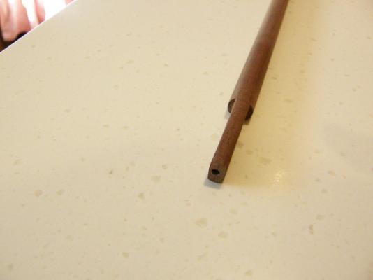
I have painted and finished the wolding for the foremast. I am reasonably happy with it, though BE has really set the standard.
I will be going to the UK for a couple of weeks in about 10 days and hope to see the Victory in Plymouth.
I'll certainly steer clear of the cricket.
- freewheelinguy and kier
-
 2
2
-
Arthur: I have looked at the remaining caps supplied with the kit, and not surprisingly have the same faults as the foremast cap. I think I will redo them as well.
Today I finally gave the painted hull a coat of Estapol (polyurethane) to protect it. It is mid-winter here and the temperature in the only space I have for spraying paint all over the place is an unheated workroom under the house. Estapol needs to be applied and dried at 10 deg C or warmer. The early mornings have been around 8 Deg C for the last couple of weeks, so it has been quite frustrating waiting for a warmer couple of days.
The Estapol has given a really good finish to the paintwork, and I can start the coppering this week; something I have been putting off anyway.
Concurrently I am working on the masts and looking at BE's work as a guide to how it should be done.
-
David: thanks for the encouragement.
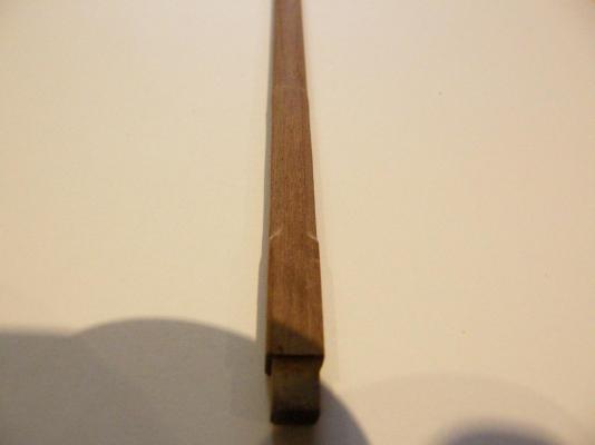
I was unhappy with the 'repair' to the cap for the foremast that I messed up earlier.
I have made another that has turned out quite well. I may do the same for the remaining caps which all have two holes, instead of one circular, one square. I have rounded the cap's corners as advised by BE.
The job was a bit fiddly, but for those who are interested, this is one way to do it.
The cap is supposed to be in two pieces, with the overall dimensions being L24xB6xD5mm.
I took two pieces of 6x6mm walnut about 50mm long and glued them together with CA, leaving a gap in the centre of about 30mm without glue. I then sanded the resulting piece to the correct (5mm) depth, then drilled a 6mm hole in the centre of the two pieces for the topmast. Both of the glued ends were chopped off leaving the 'glueless' 24mm in the centre and thus, the two separate halves of the cap. The notches for square holes were then cut in each half.


Here the two halves are held together by tape and dry-fitted to the foremast.

-
Hi Mitsuaki
I have just rediscovered you wonderful log. I am at the stage of contemplating coppering my Vanguard - something I have not done before. Fortunately I had actually downloaded your coppering from the old website, but this log.is even more helpful.
I would be grateful if you could answer two questions.
1. To be completely sure - you cut the plates for the stealers to approximately the required shape, but slightly larger. You stick them on. You then partially overlap those plates with the next row of complete plates leaving no gap between the rows of plates. (I hope this makes sense.) Any overlapping causes no problem?
2. Each row of plates supplied in the kit comprises seven plates. Where possible, did you apply the complete row of seven plates, or apply each plate separately?
Welcome back.
Regards Bob (RMC)
-
Sorry Arthur, I have a quick touch-up job at the Sistine Chapel that takes priority - but I'll get back to you....
-
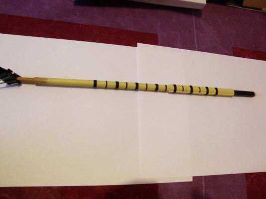
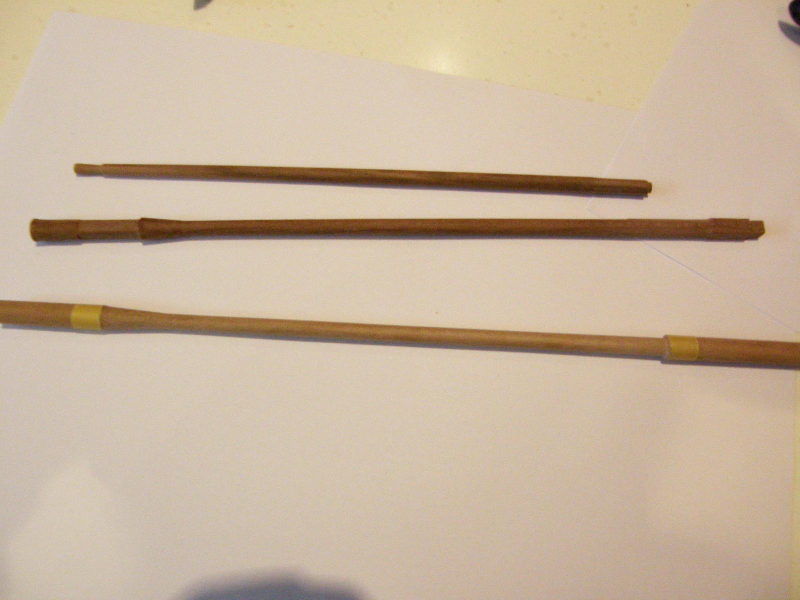
I had the opportunity to practice with the Proxxon lathe. It's really nice little machine and I am delighted with it. Over the weekend I completed the parts of the three topmasts where turning was necessary. Without the lathe the job would have been very difficult indeed. Now come the hard parts where the masts are squared or octagonal. I am waiting for delivery of the extra lathe bed (as suggested by BE) and will work on the longer masts/spars when it arrives.
In the meantime here are some pictures of the figurehead, though I see now that the pictures are larger, there is still a bit of touching up to do. As well, I belatedly discovered that the hole for his sword is not deep enough which is a nuisance. A suggestion/reminder for those who have not so far began painting their figurehead; give it a good wash with something like acetone to help the paint adhere. Unfortunately I forgot. A tip given to me by a (portrait) painter is to dip brushes in linseed oil and wipe off after washing them in mineral turpentine. They become even cleaner and it preserves the bushes really well.


- mort stoll, freewheelinguy, Timmo and 1 other
-
4
-
Thanks for the comment Arthur. I didn't think of how the the head rails may be affected. I will play around with them to make sure everything fits.
Painting figureheads? Fortunately I am quite short-sighted, with a reasonably steady hand, and some REALLY fine brushes. Unfortunately, advice is the best I can offer, but please don't let me stop you from sending cash anyway. It would certainly be a nice touch.
Regards
Bob
-
After some heart-stopping moments and some advice from Arthur (AEW) I have adjusted the stem to properly accommodate the figure head below the bowsprit. This entailed making a 10mm cut in the notch of the stem, and making provision for the figurehead's cloak (which I also trimmed very slightly), so that it is 10mm lower than it would otherwise be.
This is the position of the figurehead with the unmodified stem. He would have needed to suffer decapitation to fit under the bowsprit.

This shows the modification.


The painting of the figurehead is work-in-progress.

Here are the dimensions of the modification.

-
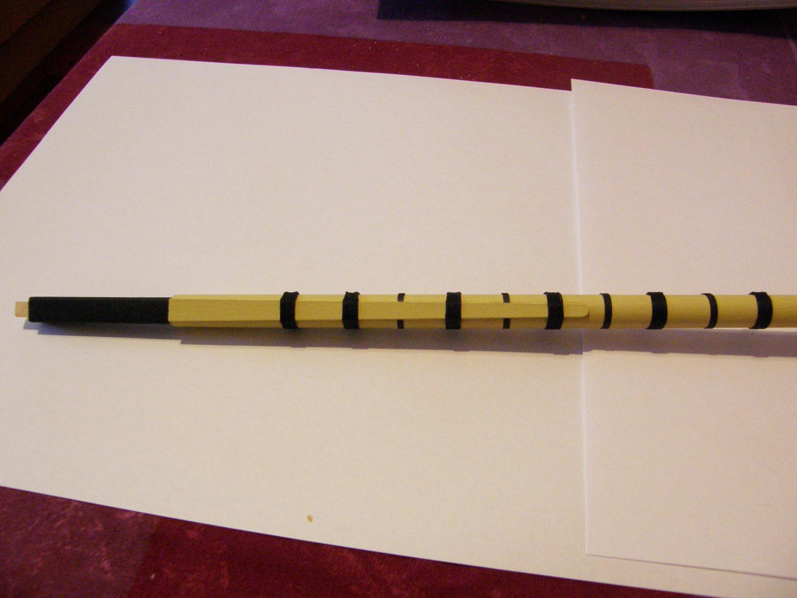
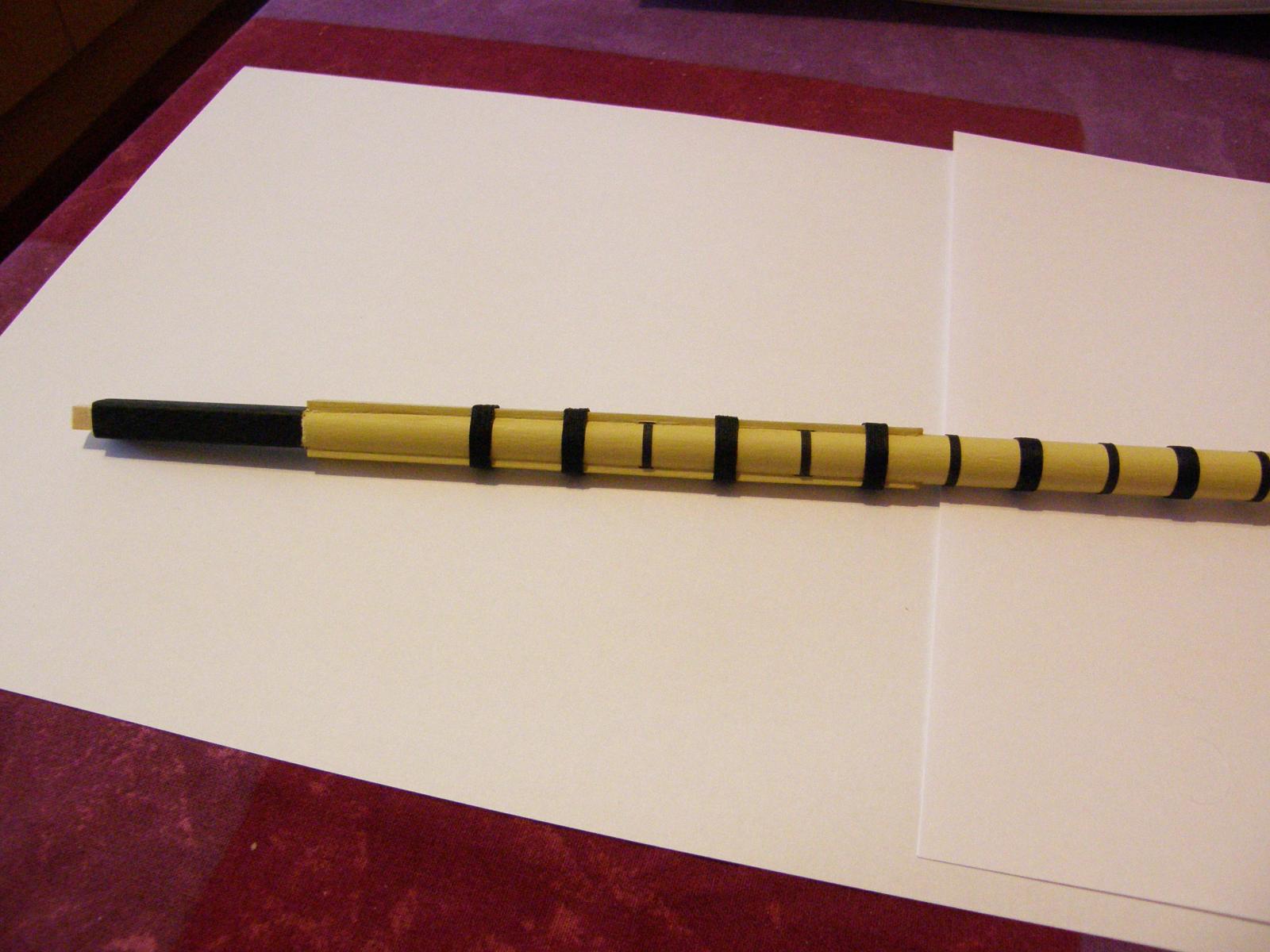
I have finished painting the stripes. Masking over the different levels was rather a pain, but came out quite well with some minor touching up. The Tamiya tape is indispensable. The irregularities you see below the lowest stripe are below the 1mm timber 'boundary' and will be covered by the copper.
I will modify the stem so that it will enable the fitting of the figurehead. (See Arthur's (AEW) log.) Then there are a few mor bits and pieces to do before I start the coppering. I'm approaching that with some trepidation.


Here the roundhouse etc have been dry-fitted.

- mtaylor, Blueskippy, Ray and 1 other
-
4
-
David: thanks for the encouragement.
BE: The temptation to buy the milling machine is difficult to resist. I presume the one you have is the Proxxon Micro mill MF 70. This costs about $560 here plus shipping. I wonder whether buying it is justified, given the amount of use I would make of it at the moment. While I would love to do as good a job on my masts and yards as you are doing, I think it's a bit beyond me just now.
My longer term plan is to use the Vanguard as practice - doing as good a job as I can - and hoping that Chris Watton's Bellona will become available in a year or two.
-
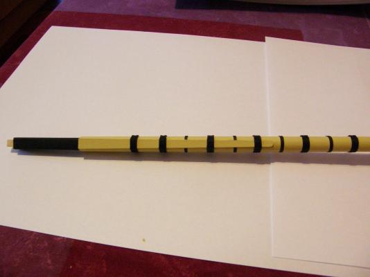
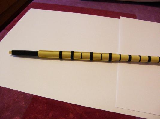
While away I've had the chance to play with the Proxxon lathe. It's a really lovely little machine. Below are some pictures of work-in-progress: the jib boom; the fore topmast and the main topmast. Unfortunately the photos don't show the detail very well.
The octagonal sections have turned out quite acceptably. In these cases I have first, made a square section, then turning that square at 45 degrees, made another 'square' with the same dimension as the first which then trims off the edges of the original square so creating an octagon. I check the width of each octagonal face by drawing a large circle on paper then drawing rays from the centre of the circle at 45 degrees. I then draw circles of the required diameter of the mast I am working on, and measure the distance between where two rays intersect the circle. This gives the width of the octagonal faces.
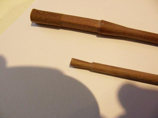
I have been worried about making the square sections at each end of the masts 'line up' so that the caps etc are properly aligned. My solution is to cut the square sections as accurately as I can (I use a heavy craft knife, then a file), but very slightly larger than is specified. I then clamp a piece of wood strip to the sides of the two sections lining them up to see if the two sides are parallel. If they are a little out of parallel, I have sufficient room to make any slight adjustment that may be needed. It seems to work, though I envy BE's milling machine.
-
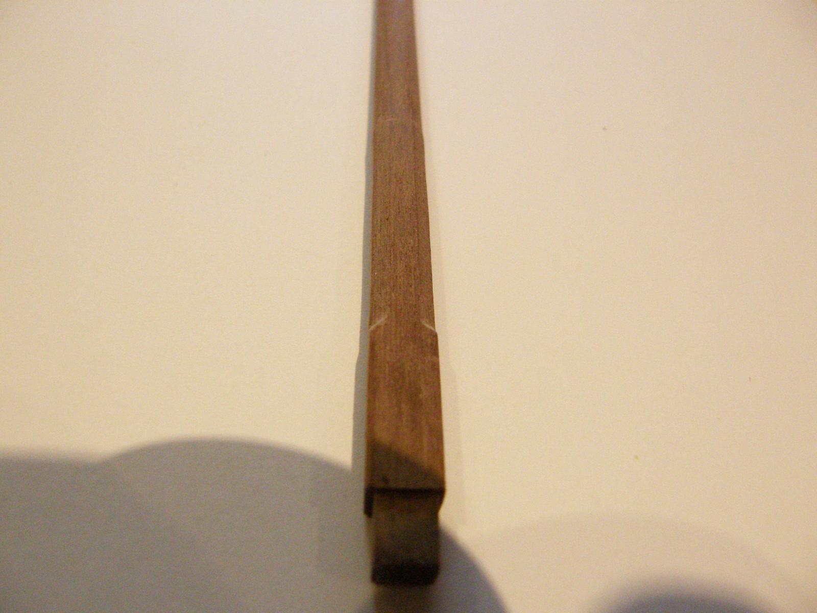
Having redone the cap, I have now adjusted the top of the mast to receive it. As i wrote earlier, the cap will later be cleaned up and painted. (Question for BE: your caps have rounded corners - is that the generally correct way or is it unique to Pegasis?) I have also sanded the sides of the mast ready for the cheeks. Here they are taped on.


In the meantime I have finally finished painting the stripes for the nelson checker. I painted each one separately so that I could get the depth of each stripe accurately, and each one took at least a day to dry ready for sanding. All told it has taken nearly a month - not that I'm bitter. There is still some very minor touching up to do, but it has turned out well. The yellow needed 5 coats, and the black four. I have found with the Humbrol enamel that it is best to thin it by about 5-10% so that it goes on smoothly and without brush strokes. The following pictures are a bit rough, but I will take some better ones during the touching up process.


-
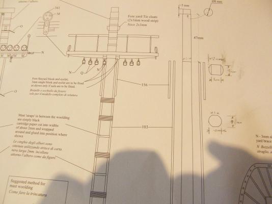
I do plan to rig it - without sails. I just looked up 'shrouds' (you can see how much I know about ships) and can see why it will be far easier to rig them before the cap etc., go on.
Bob
-
Arthur and BE: Thanks for your replies. They saved me from making a large mistake.
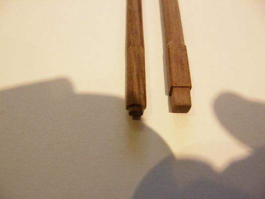
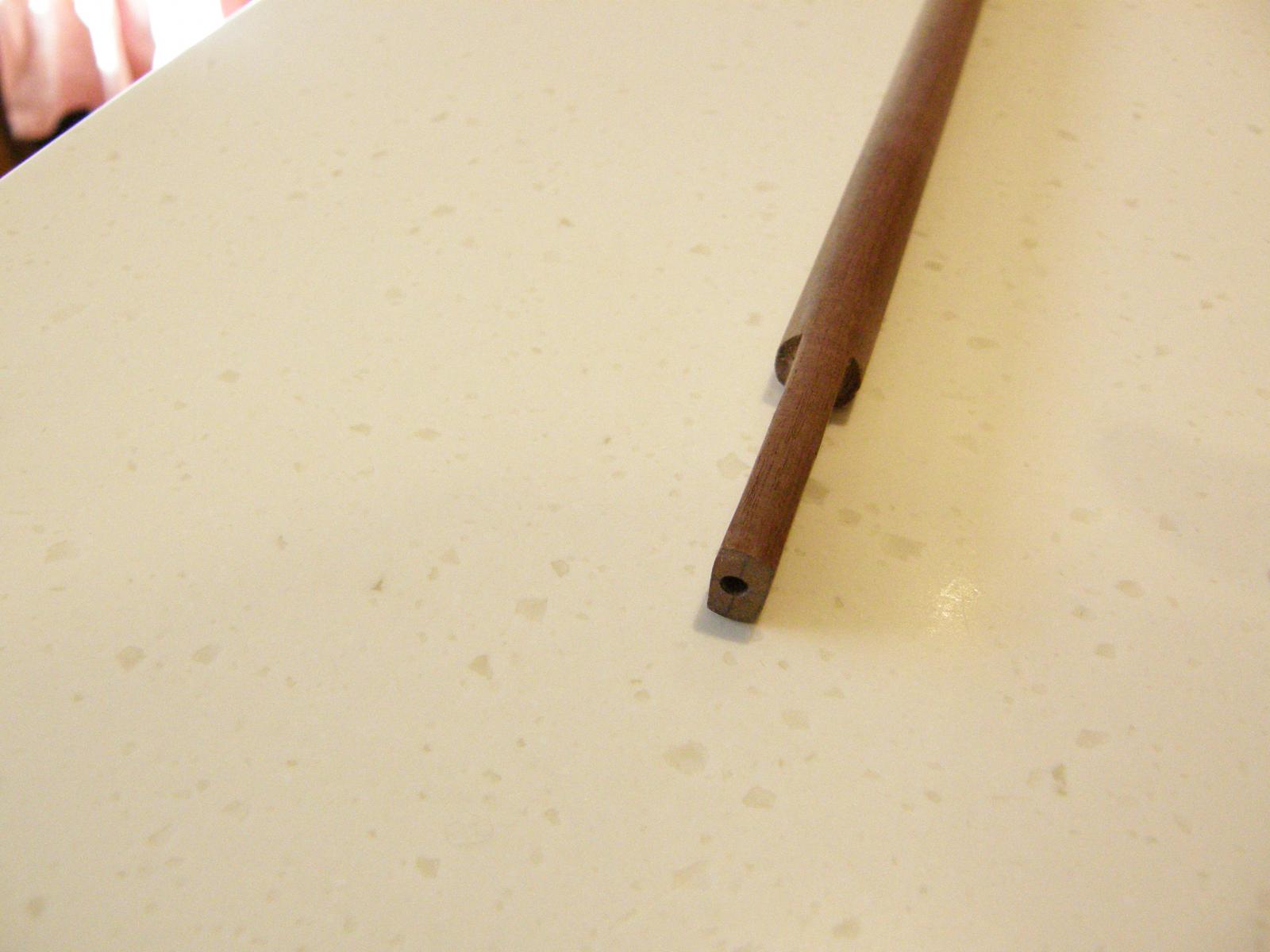
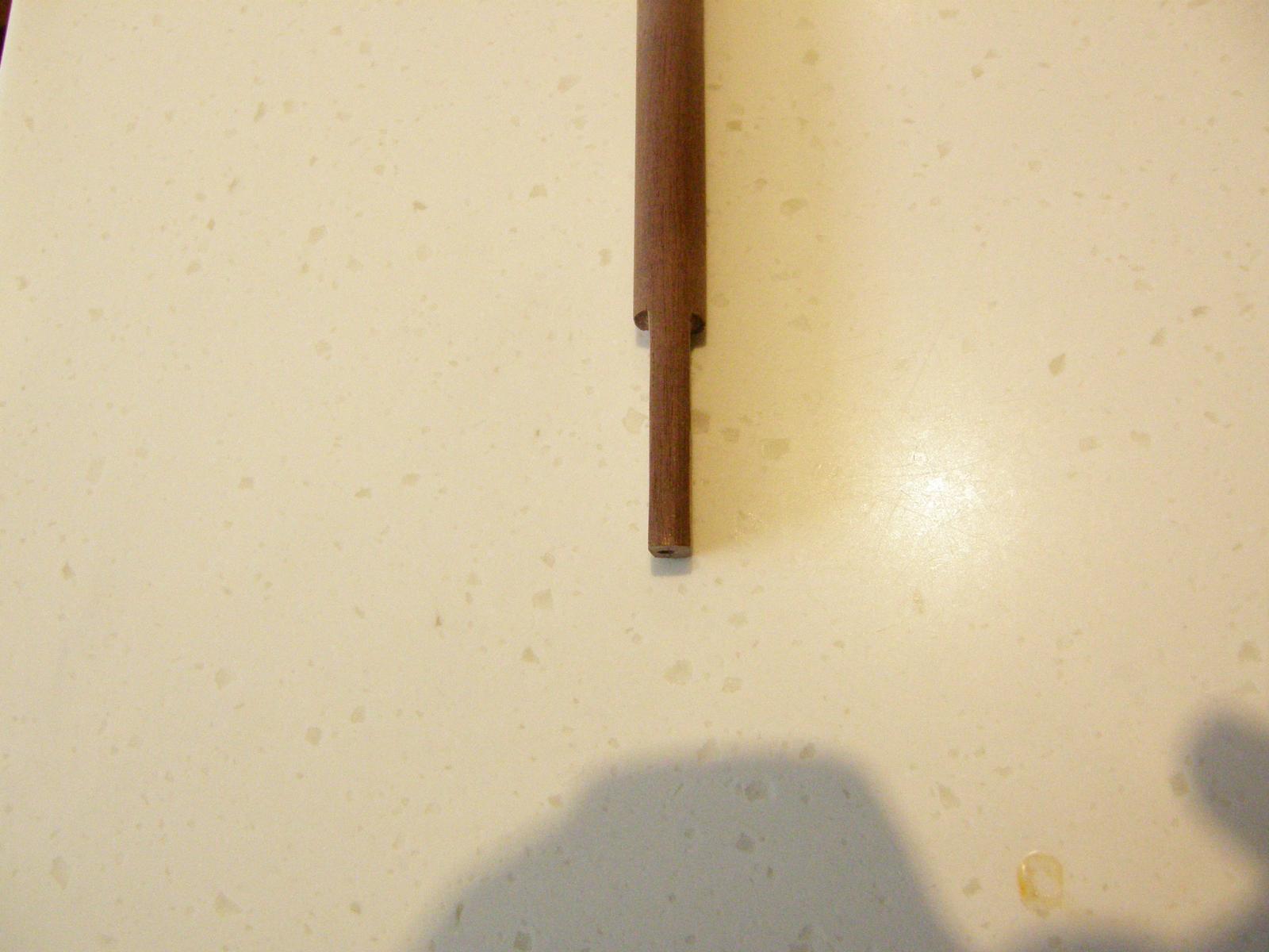
I have filled in the large square hole I made in the cap so that it is now 5mm square ready to receive the lower mast. I have enlarged the small hole to the dimensions of the topmast shown on the plan - about 6.5mm (I can further enlarge it if necessary). While the resulting cap looks a bit ratty, once it is cleaned up a bit and is painted it will be fine. The pictures show the two halves taped together. I would appreciate your comments on whether or not this does the trick.


-
Woops. I just realized my mistake regarding the small round hole in the cap. Of course it should be round. It doesn't receive the topmast at all. It provides support further up the topmast. Oh well....
-
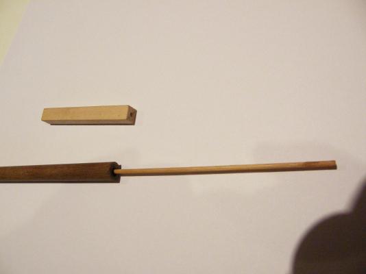
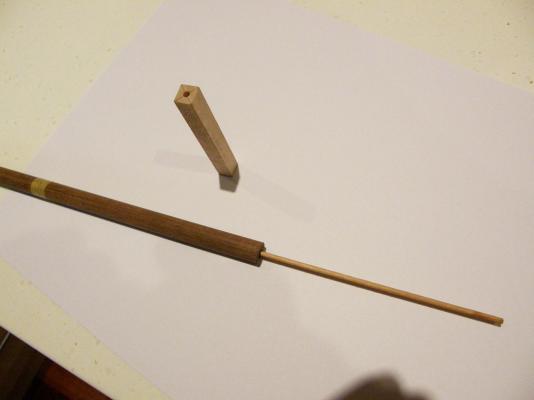
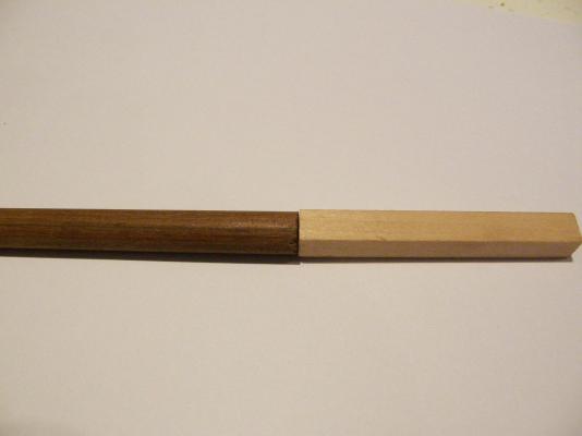
I have now attached the square boxwood to the lower dowel and sanded off the dowel to receive the cheeks. The kit provides caps with round holes. I have made the larger hole square following BE's log as a guide. The odd thing now is that the plans specify a square section for the portion of the topmast that goes into the cap. So I suppose the smaller hole in the cap should be also 'squared', but in every other cap I have seen the hole to receive the topmast is round. I am inclined to ignore the plan and go with the round. Comments/advice is welcome.


The cap is in two parts taped together, and dry-fitted.


-
Andy: thanks for the advice - I'll take it.
Arthur: No, I'm not going to fit the masts before coppering. I spend quite a bit of time away from home, and as the model is at a stage when it is easily damaged, I'm using the masts as a 'mobile' project to take away with me. Thanks for the tip regarding the mizzen.
Regards
Bob
-
Again I have no idea what happened to the post I just wrote. Here are some progress pictures of the dreaded Nelson checker. The painting shown in the photos has not yet been touched up. The Tamiya tape gives a very clean line between the colours and touching up is comparatively easy, and gives an almost perfect finish.
-
Hi B.E. Alas, it pays to read the instructions - though they are (to me) also moderately confusing. It seemed to me from the cross-section shown on the plan that the mast above the cheeks etc is circular and 8mm in diameter. Oh well ... As I now have to buy some more 12mm dowel as Amati short-changed me, I may as well get some spare stuff with which to experiment.
My main concern in doing the square sections is lining them up correctly, and unlike you I do not have a beautiful milling machine to do the job with accuracy. I am tempted to buy one, but having just bought the lathe and a Dremel drill press, my wife may retaliate and buy another sewing machine for her quilting. This would make it a very expensive milling machine indeed.
In the meantime I will cut off the offending circular piece above the cheeks and attach a piece of square with a piece of dowel inserted in the square and a hole in the dowel to receive it. I am still searching for a supply of good quality square of the appropriate dimensions.
I am still painting the Nelson checker. The masking I find is both time-consuming and rather tedious. I wish Nelson had kept his decorating ideas to himself.
This will be the third time I have described these pictures. Maybe it all appears somewhere else in this log - who knows. It is very frustrating; and why this is attached to an earlier post is also a mystery. These are just progress pictures of the painting of the dreaded Nelson checker - not yet touched up.


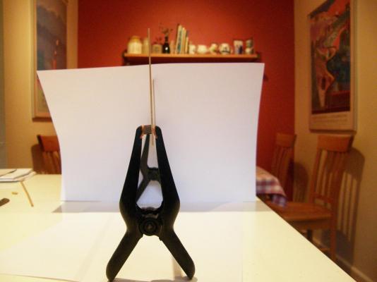
While waiting for paint to dry (not a spectator sport) I have experimented with my new toys. As I earlier wrote, correctly lining up the flat surfaces of the various masts are a concern. For the foremast I have put some square boxwood onto the dowel supplied in the kit. I have drilled holes in both the square piece and the dowel and then 'lined-up' the square by clamping a straight piece of strip to the square and lining it up so that it is parallel to centre line of the model.
I have initially left the dowel long so that it is easy to make sure that it is indeed vertical.

I have had plenty of time waiting for paint to dry, so while in painting mode I have started painting the decorations. I won't attach the stern facia until I have done the coppering. Icidentally has anyone some advice on whether it is best to attach the decorations to the facia before fitting the facia to the model?

-
Making the foremast has not gone smoothly. When I put the dowel in the hole provided, two pieces of the framework prevented it from going right to the bottom of the 'well'. Whether I have done something wrong in putting the framework together (there's no other evidence of that) of this one of the little oversights in the plans, I suppose is immaterial. It required me to trim the bottom of the dowel to fit. This really is a nuisance as parts of the mast have flat surfaces that must be parallel fore and aft and must match the flats I have cut to fit in the hole.
-
Hi B.e.
I've been away for a few days.
I have now received the lathe and set it up ready for the extra bed that will be delivered at the end of next month (I hope). I got the 3 jaw chuck as well but in the light of your advice, I guess I'd better order the 4 jaw chuck now.
I discovered over the weekend that the 12 mm dowel supplied with the kit is 500mm long, not the 800mm as specified. 500mm is insufficient to make both the bowsprit and the main mast. Buying the extra dowel is not especially expensive but the postage is pure extortion. I am quite peeved.
More and more it seems as if square stock is the way to go, though obtaining appropriate wood of the right dimensions is a problem.
Somehow the narration for the two photos below seems to be out of place as is this entire post. I have no idea what happened. (See comments on the difficulty of fitting the foremast into the holes provided on the model.)

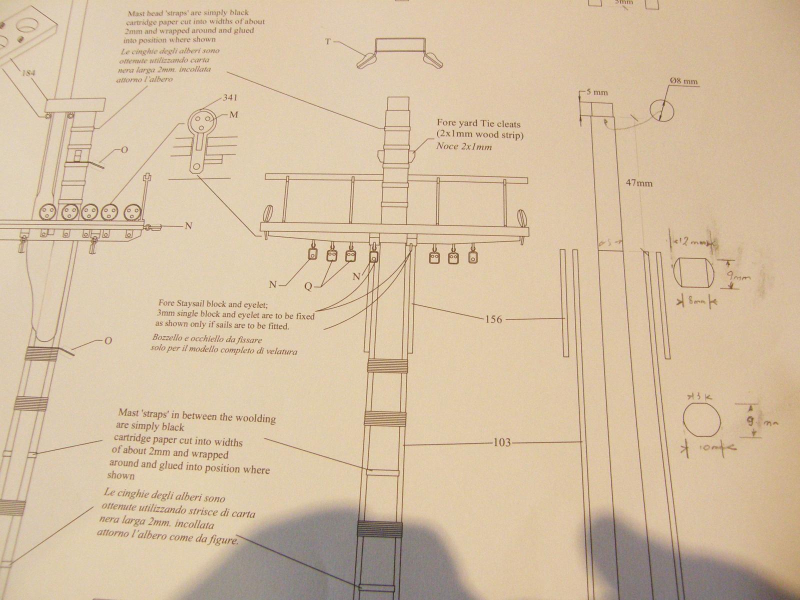
The other problem are the two cross-sections for the foremast shown on the plans. The lower cross-section seems OK with the 2 flats accommodating the foremast cheeks (part 103). The upper cross-section is apparently 12mm in diameter (the mast is 10mm) with 2 flats 8mm wide (I have written the dimensions on the plans). Incidentally, these two cross-sections are identical to those for the corresponding positions on the main mast. Both look to me to be errors in the plans.
Any help would be appreciated

-
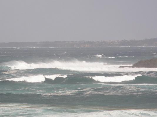
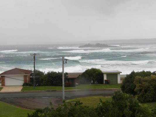
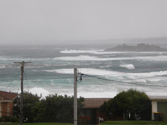
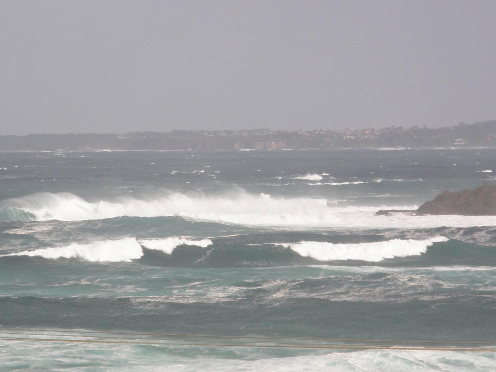
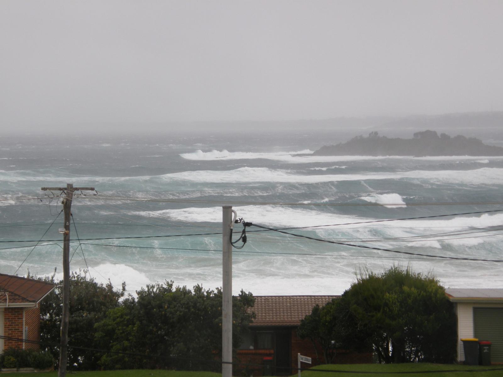
I have finall got around to putting up some pictures of one of the recent storms we have had on the coast south of Sydney. They don't really do the conditions justice. I would certainly not like to be out there in an 18th century sailing ship
-
Somehow these got out of order. the comment appears below I am now in the process of putting the black stripes on the model. The masking has proved difficult and very time-consuming. I hope to have finished the process in a week or so.


HMS Vanguard by RMC - FINISHED - Amati/Victory Models - scale 1:72
in - Kit build logs for subjects built from 1751 - 1800
Posted · Edited by RMC
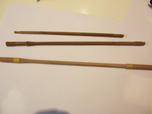
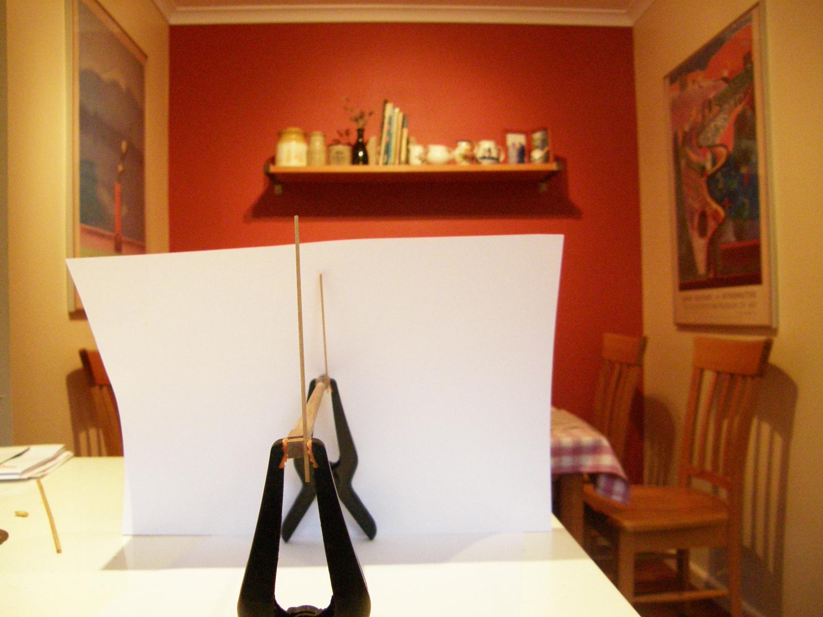
Rather than start coppering, I have decided to work on the masts in the time before I go away. Here is my method of 'squaring' the 12mm dowel for the main mast.
1. Determine the lengths of the sides of the square (in this case 8.5mm).
2. For the relevant part of the mast, run 2 pieces of masking tape parallel to each other and 8.5mm apart (this is a 'straight' distance (ie, a chord of the circle), not a measurement around the circumference of the circle (I use a compass to mark the distance).
3. Make cuts with a small saw across the curved part of the mast berween the two pieces of masking tape.
4. Cut out the the small 'rectangular' pieces of wood created by the saw cuts.
5. File the resulting rough surface smooth - the edges of which just touch the masking tape - creating a smooth surface 8.5 mm wide.
6. Repeat for the other 3 sides and (surprise - at least to me) it results in a nice square section.
I have tried to show that it IS square in the following picture but it may not be all that obvious.
It came out surprisingly well, but I still lust after BE's milling machine (maybe after a new set of golf clubs).