


RMC
-
Posts
933 -
Joined
-
Last visited
Content Type
Profiles
Forums
Gallery
Events
Posts posted by RMC
-
-
Two further points have occurred to me.
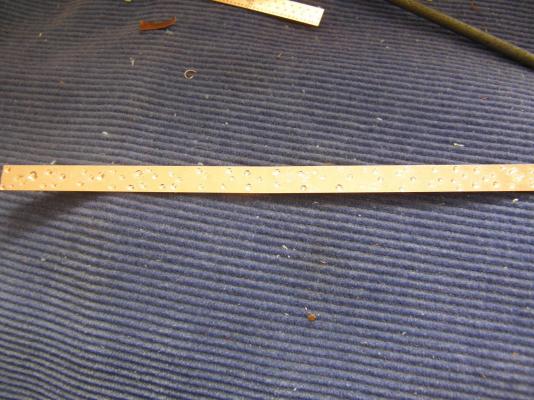
1. Bamboo meat skewers are ideal for positioning plates; and
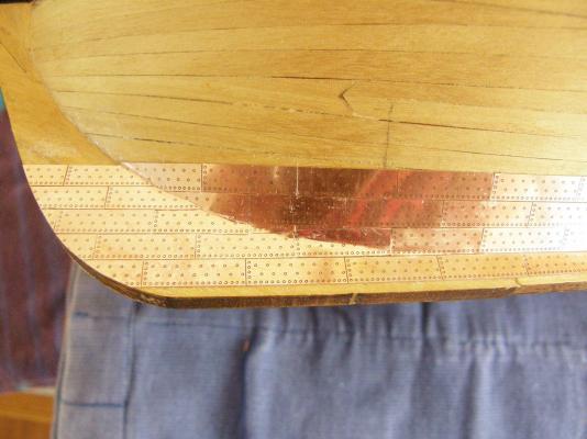
2. As you approach the waterline midship (say about 4 or 5 rows) there is a significant curve in the line of plates. Filing a very small scallop in the top of each plate (a small fraction of a mm) will minimise the gap between rows of plates. Arthur (AEW) has also made this point.
-
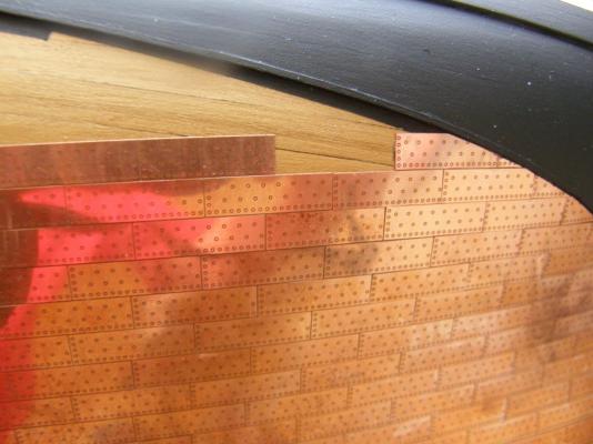
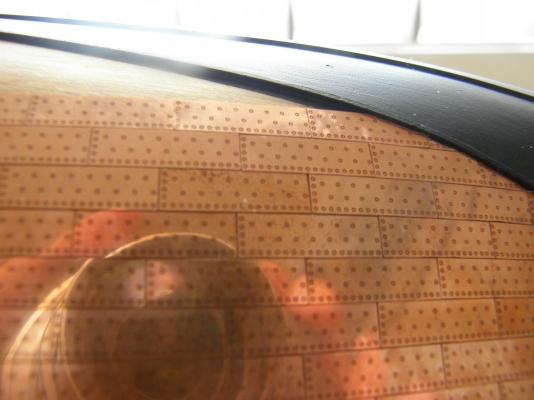
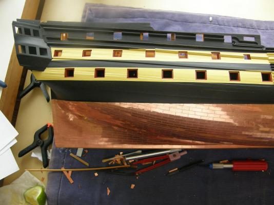
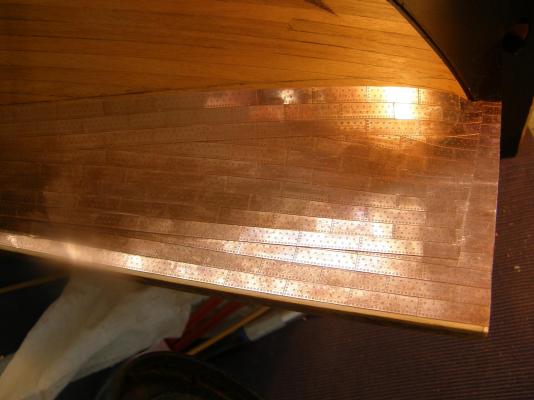
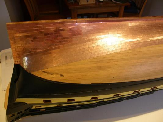
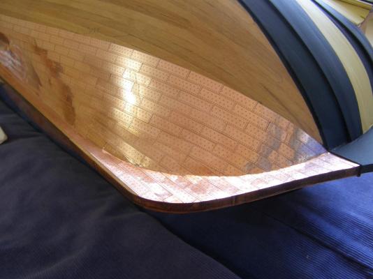
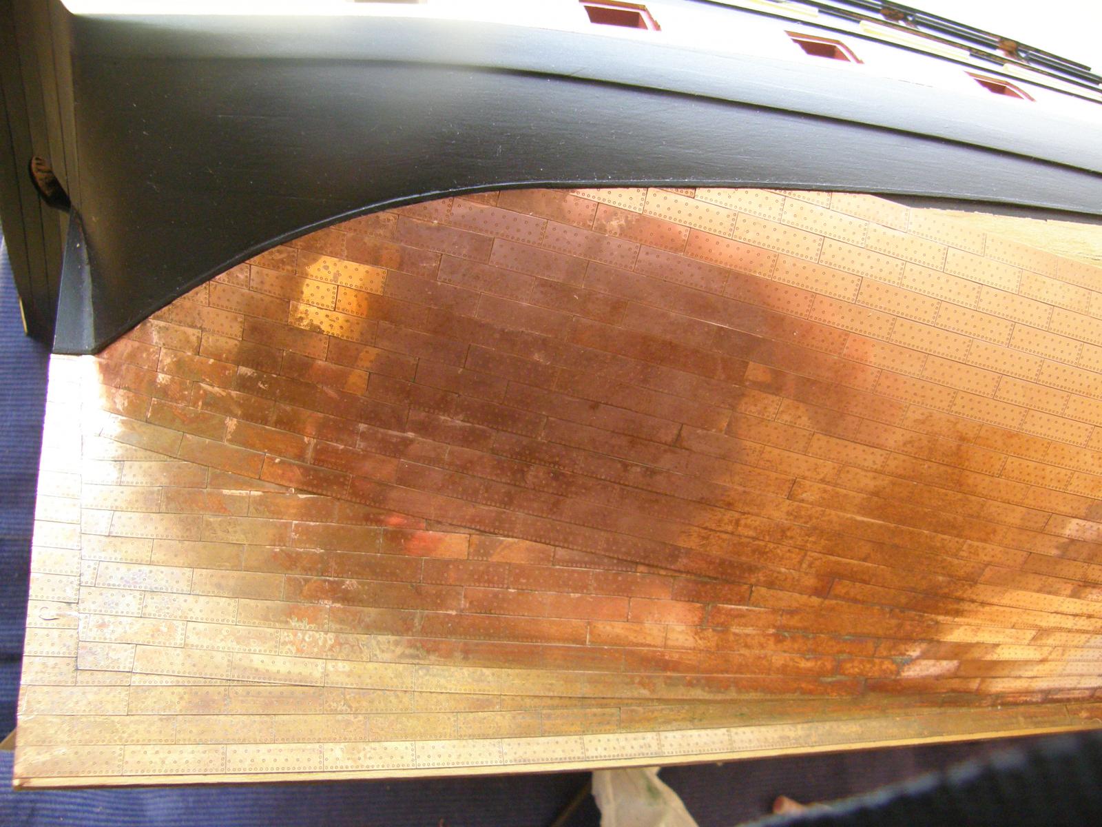
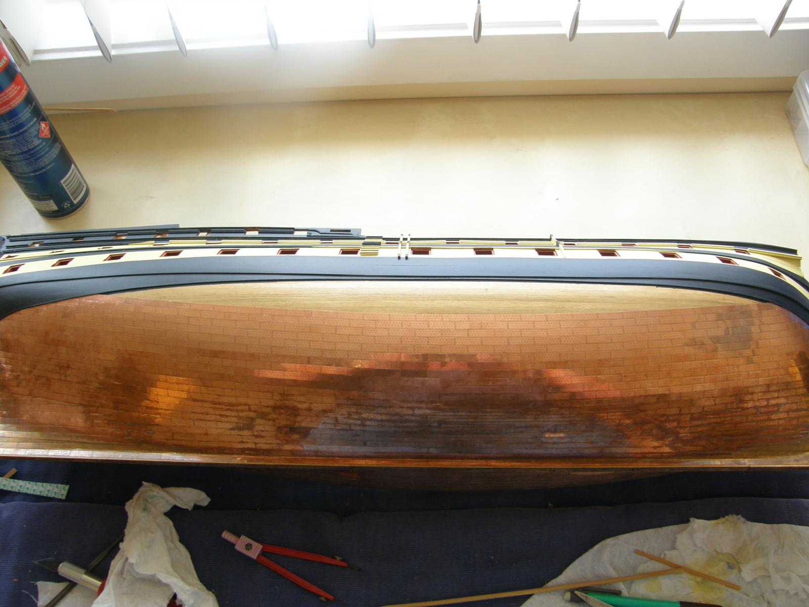
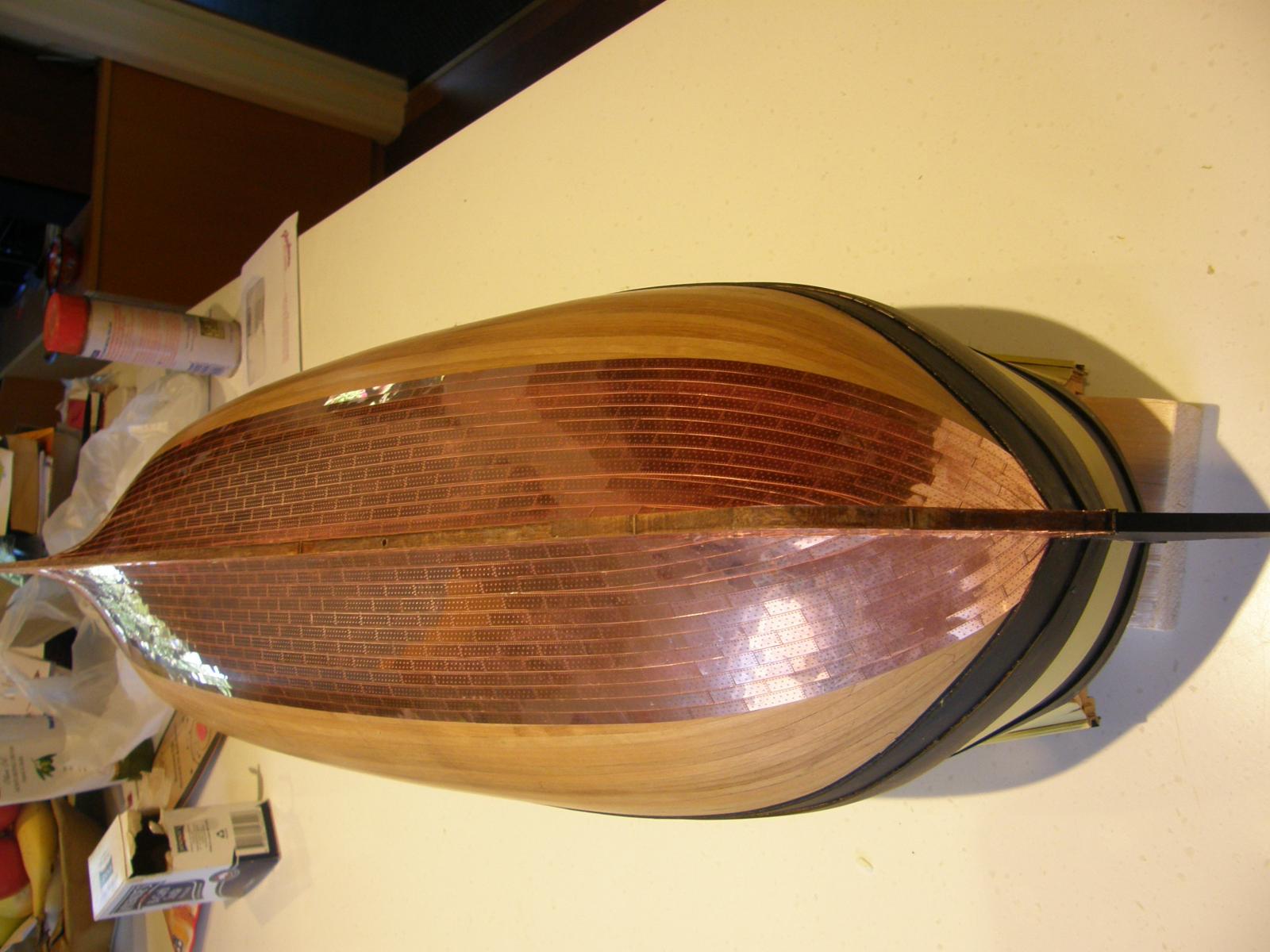
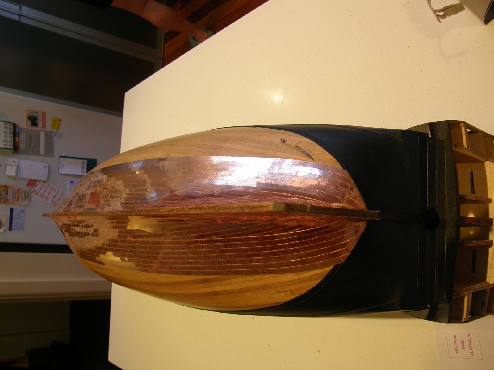
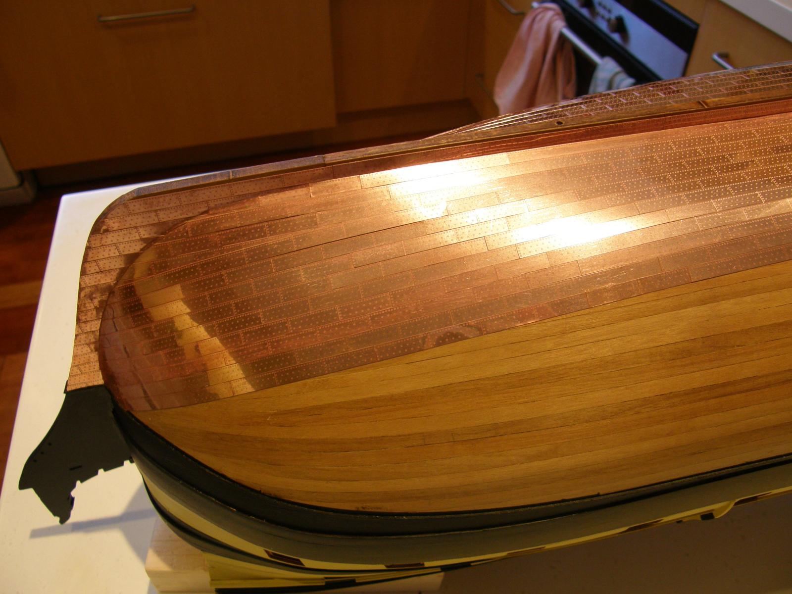
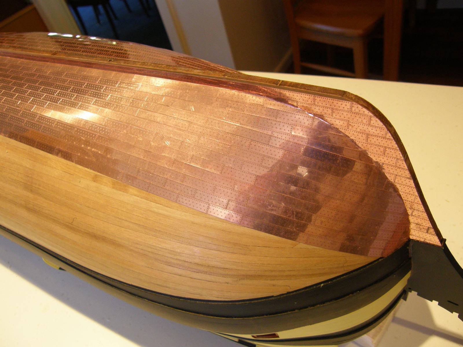
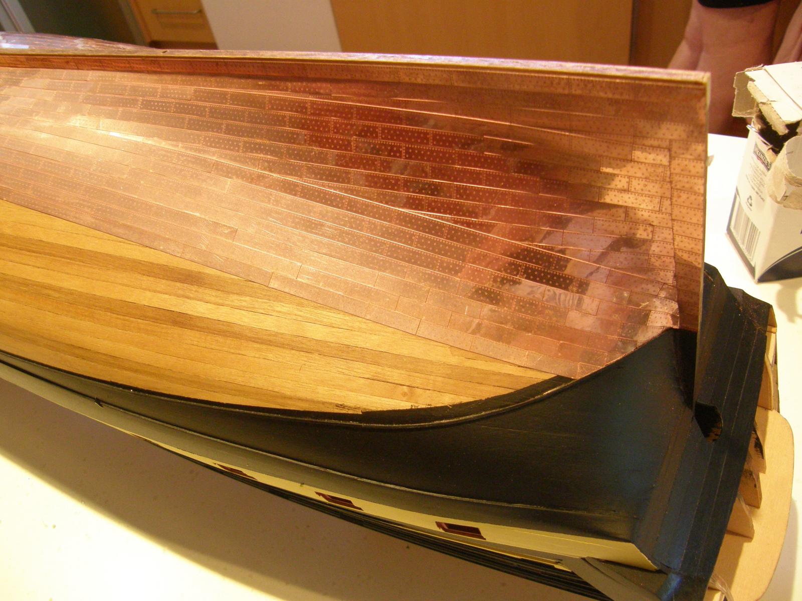
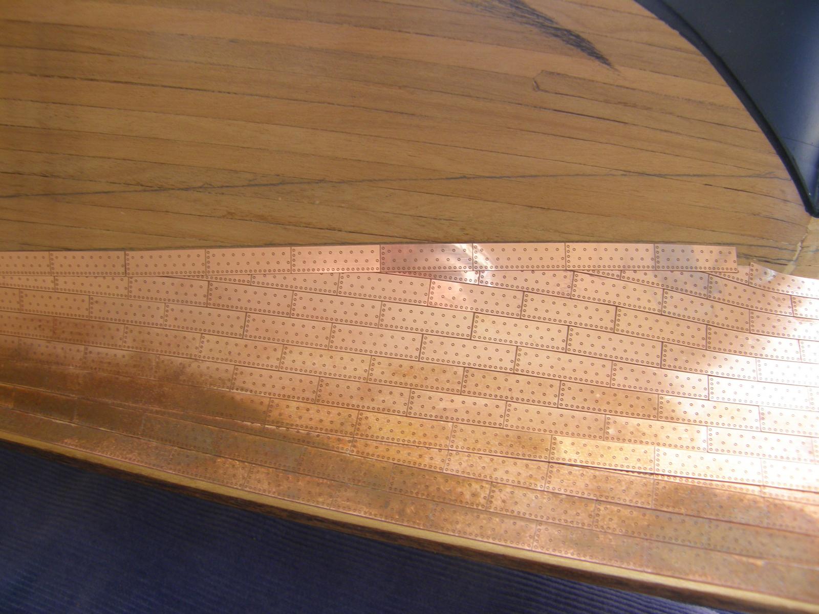
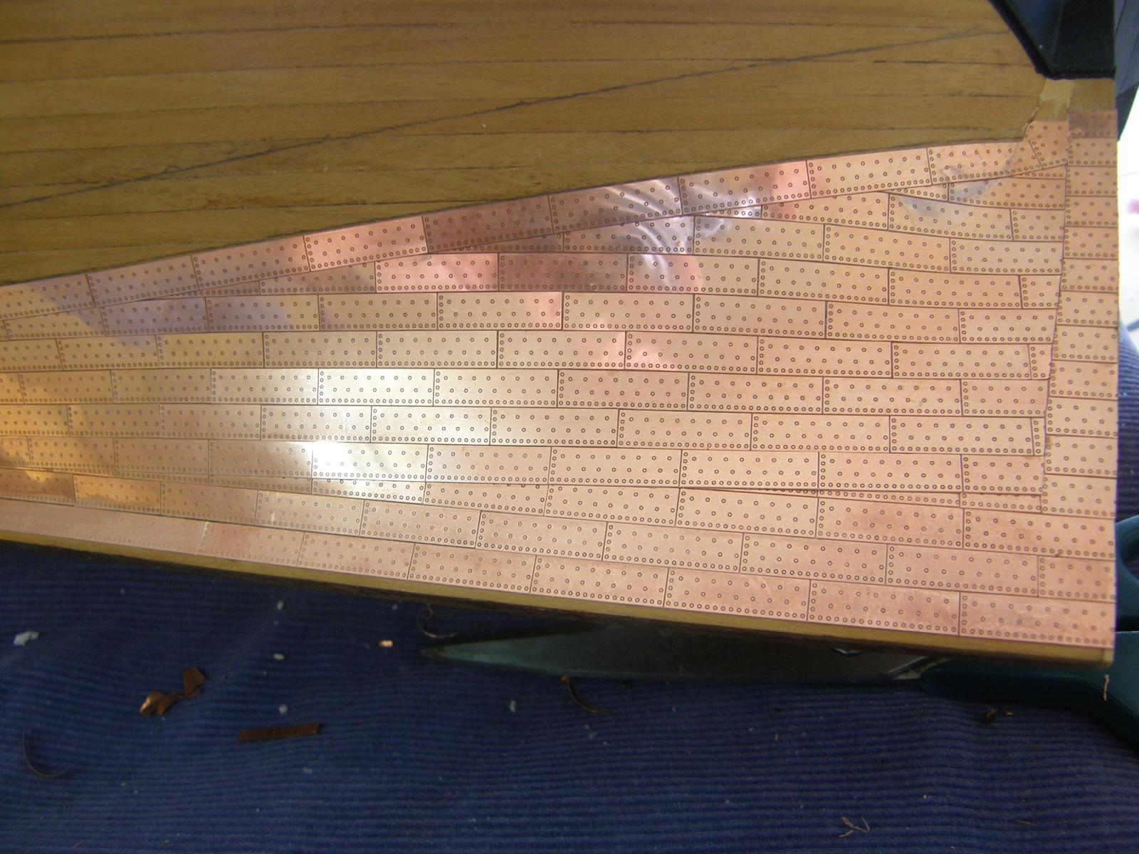
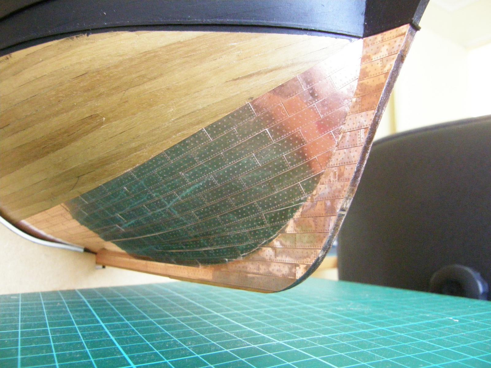
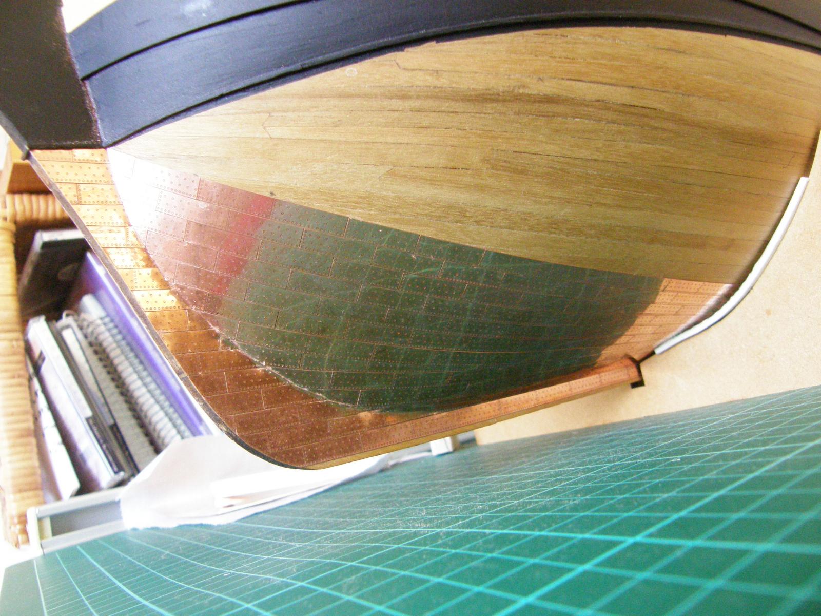
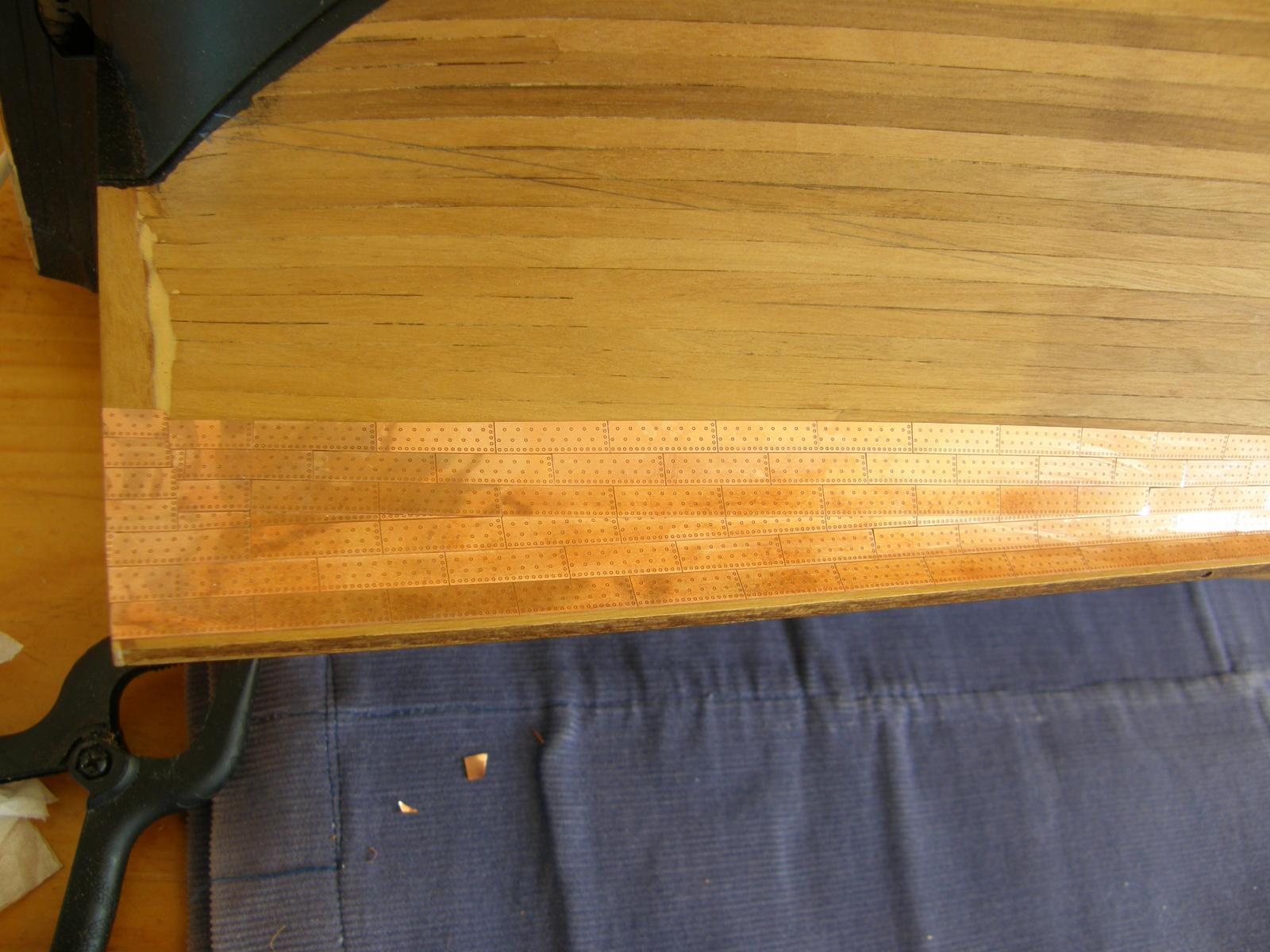
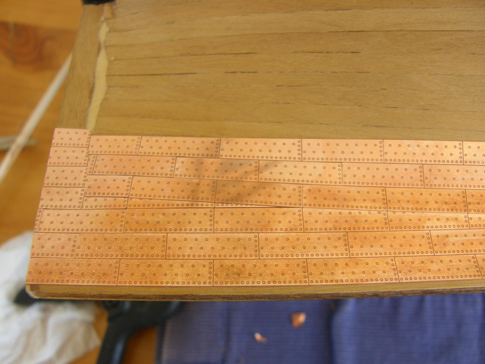
I have finally finished the coppering to the waterline on one side. The other is within a couple of rows of being finished. At the moment I am sick of the sight of copper plates. It has so far turned out acceptably. I have certainly learned a few things in the process.
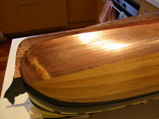
Applying the plates in complete strips to the waterline worked well - enabling accurate matching of the coppering on both sides. Once the waterline was reached, fewer and fewer could be applied at once, but the accurate placing of the strips to the waterline made it easy to accurately place the remaining plates. In effect, they fell into place as earlier I hoped they would.
I used "repositionable" CA. In general it worked well. However I would better describe it as "unpredictably repositionable". If I positioned a plate poorly, it was certain to stick instantly. On odd occasions when pressure was applied at an angle (to close up a gap) the plate leapt off the boat landing on the floor with the inevitable result that those who have dropped buttered toast know all too well. With experience I did get better at it - but then you would want to.
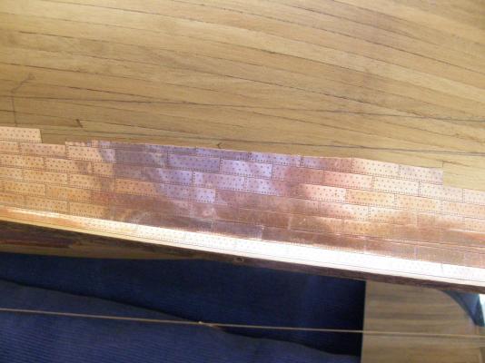
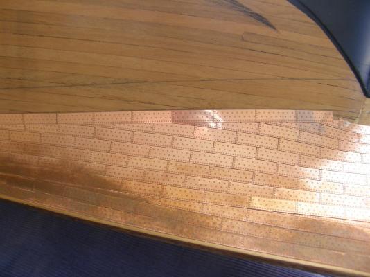
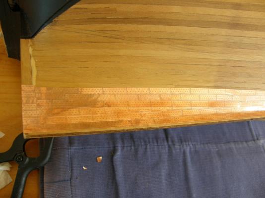
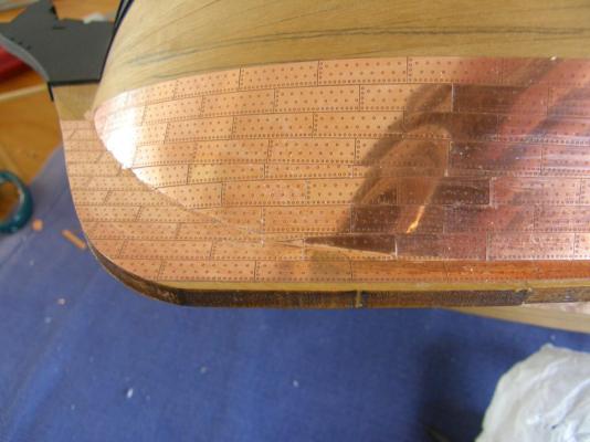
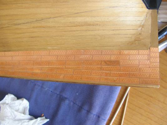
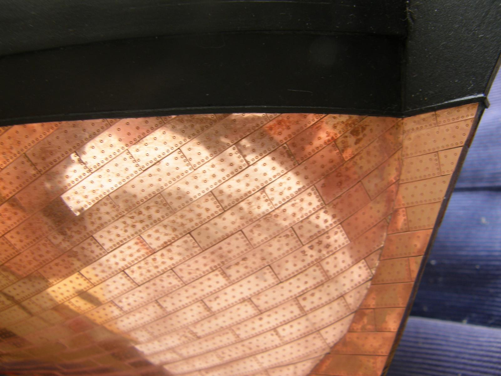
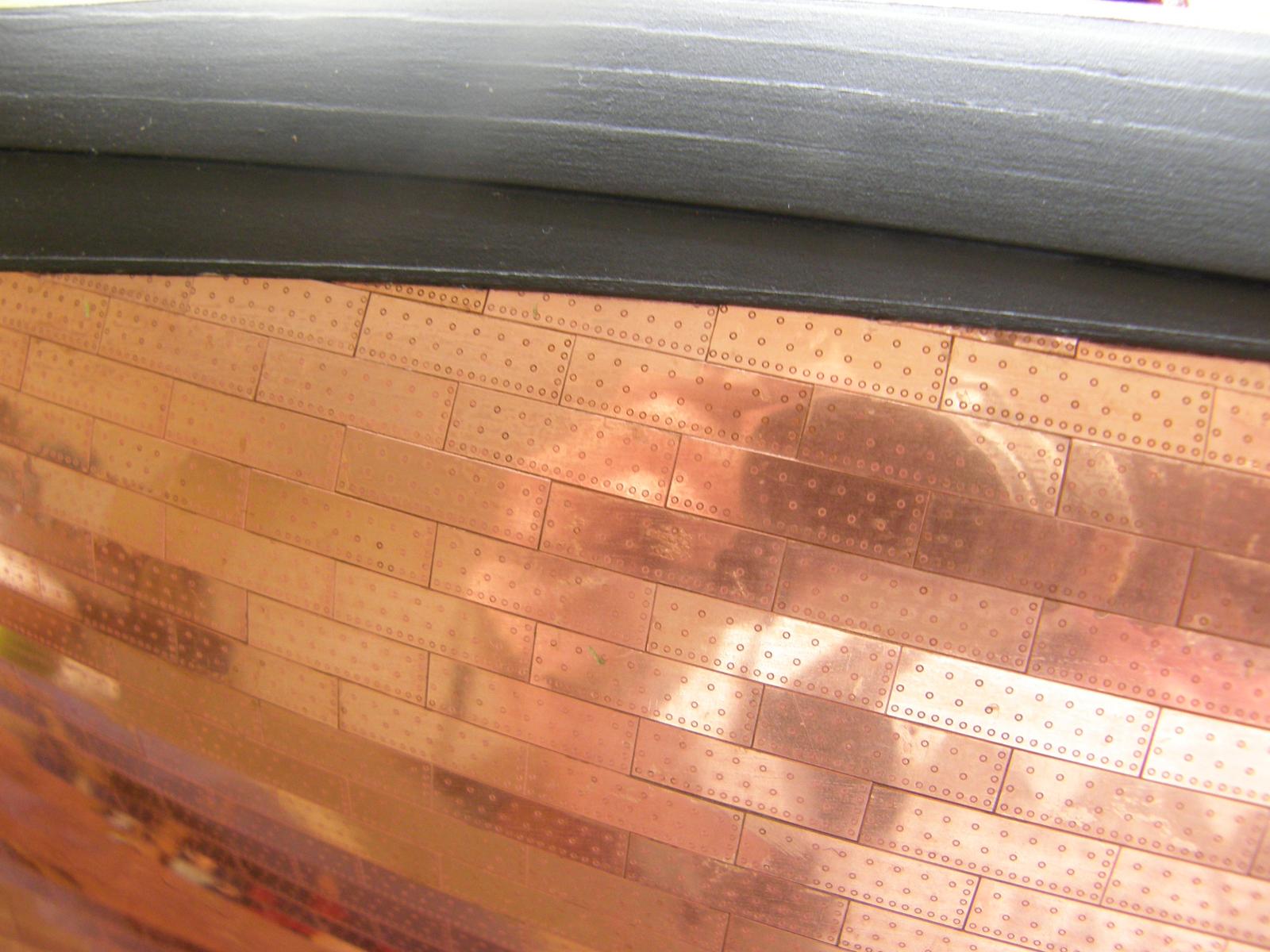
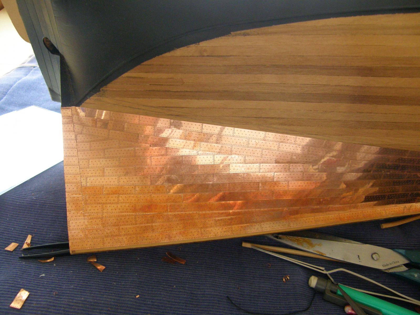
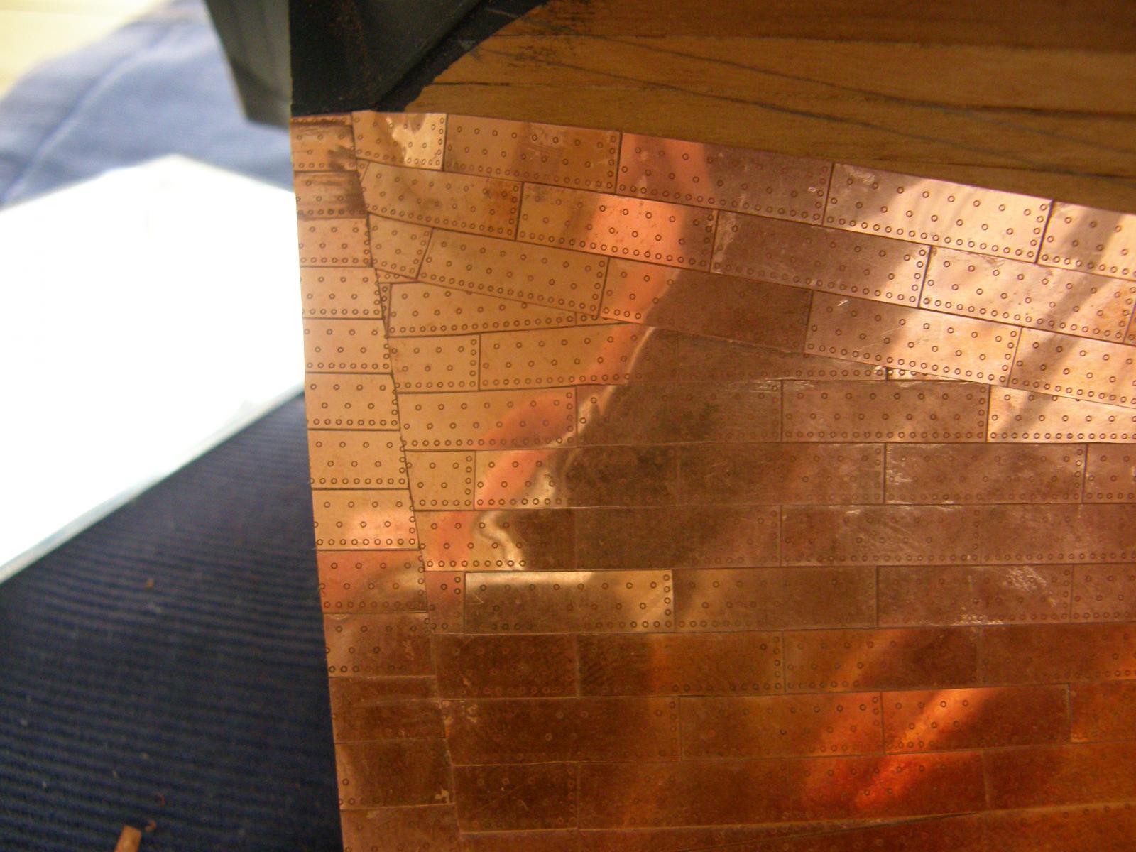
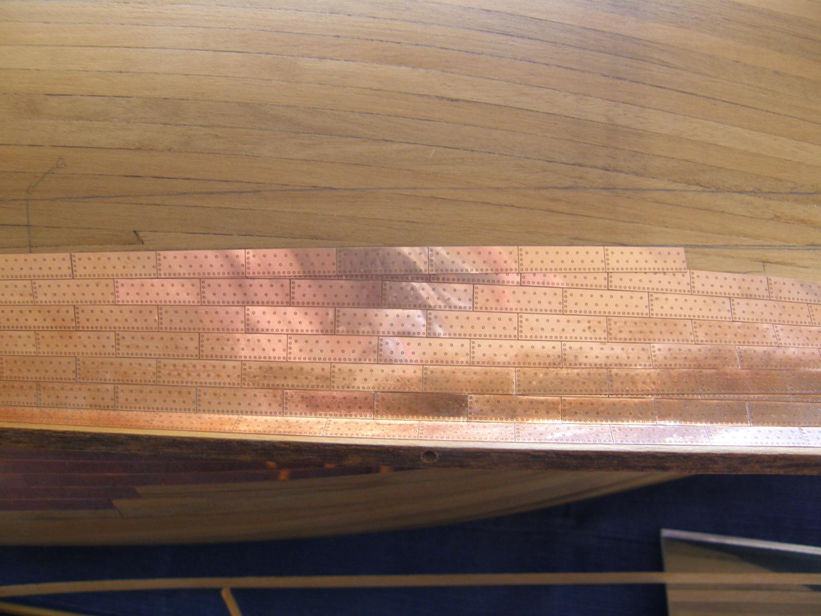
Here are some pictures of progress. The plates have been roughly cleaned with lemon juice alone.
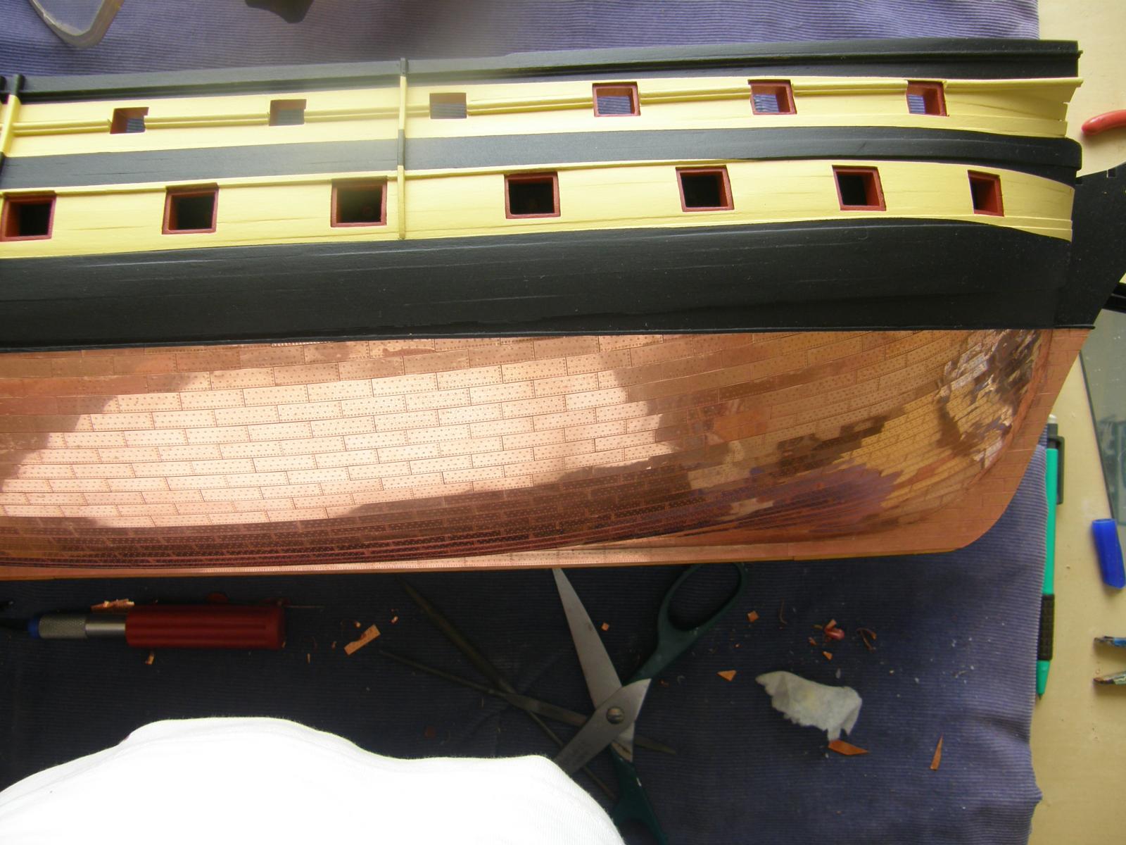
I found that when a plate needed to be shaped to fit the waterline,particularly when the required part of the plate was very small, it was best to shape that last plate so that it fitted snuggly between the waterline and the lower plate but not worrying about its length. I would test-fit the penultimate plate so that it would overlap the last plate, so providing the required length of the last plate. I then cut off the last plate to the required length, glued it and then applied the penultimate plate. On the odd occasions this was required cutting off the end of the plate was not noticeable (I hope).

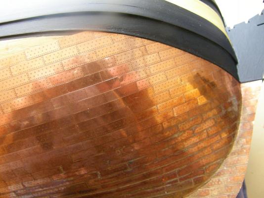
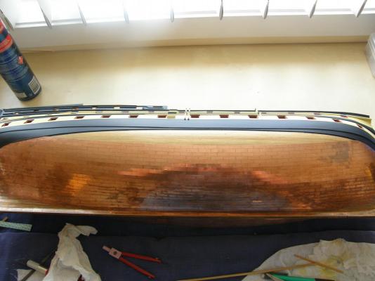
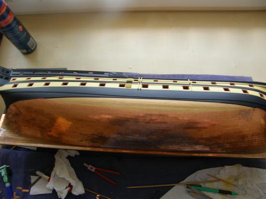
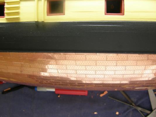
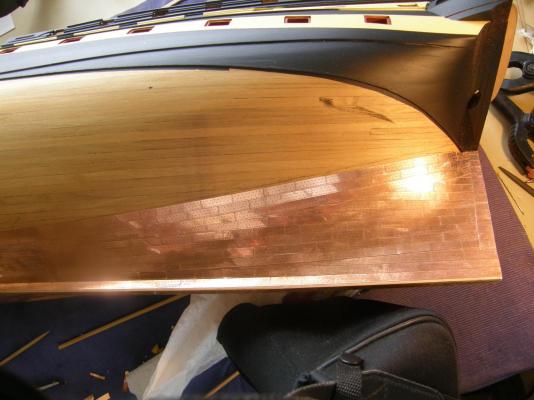
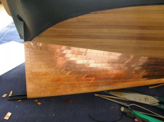
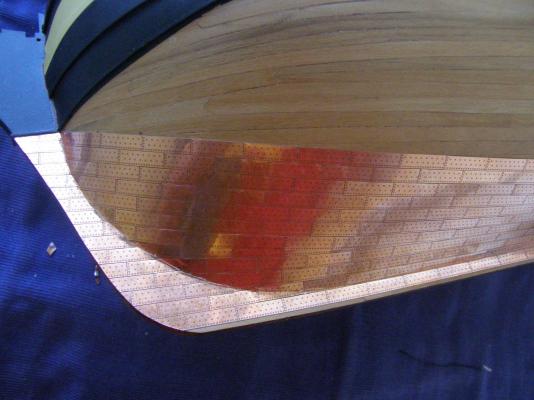
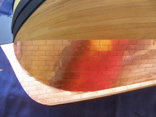
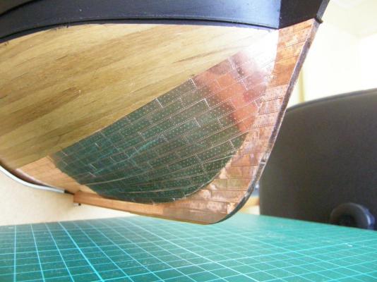
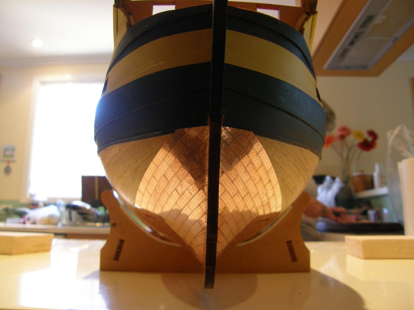
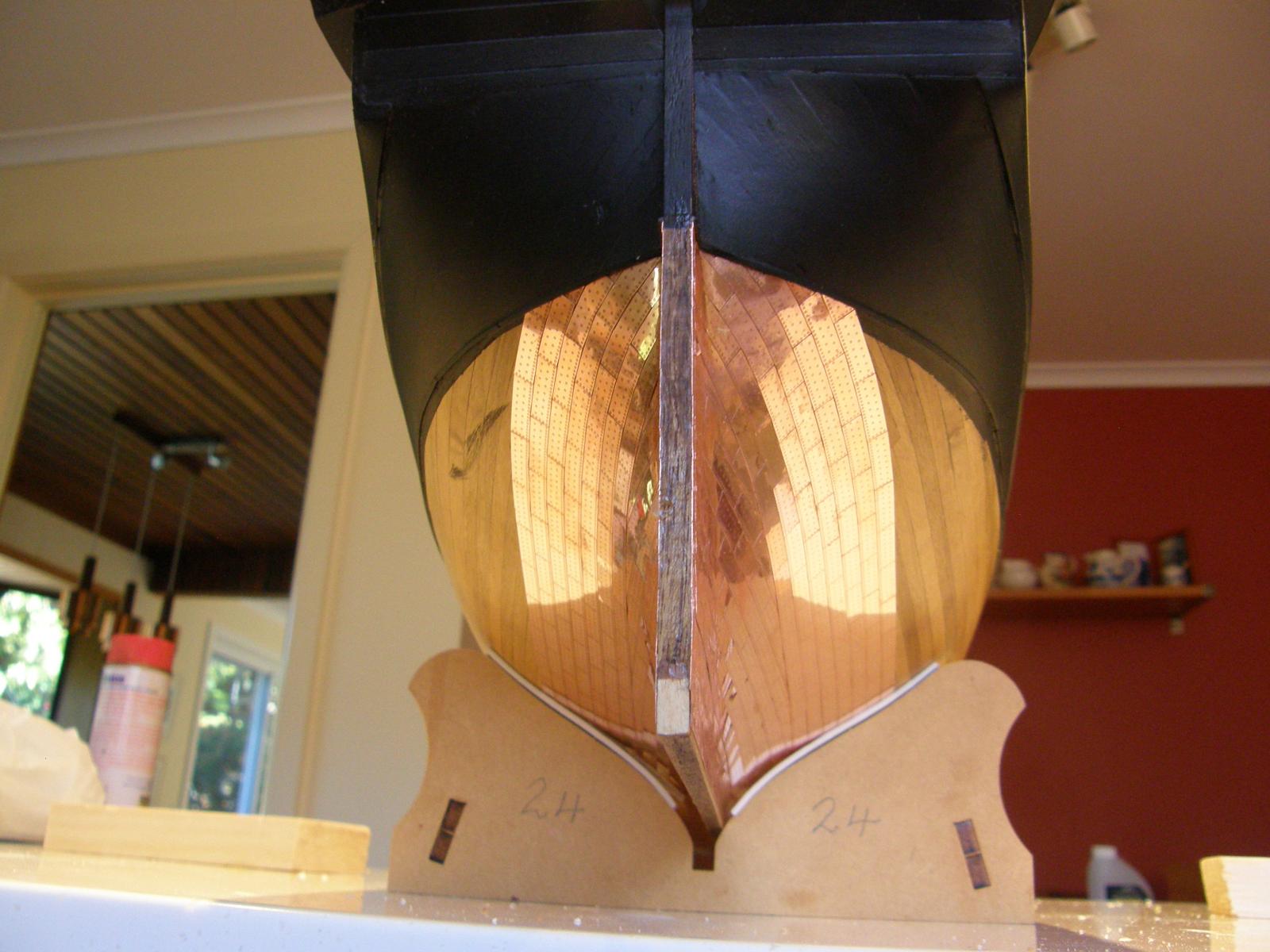
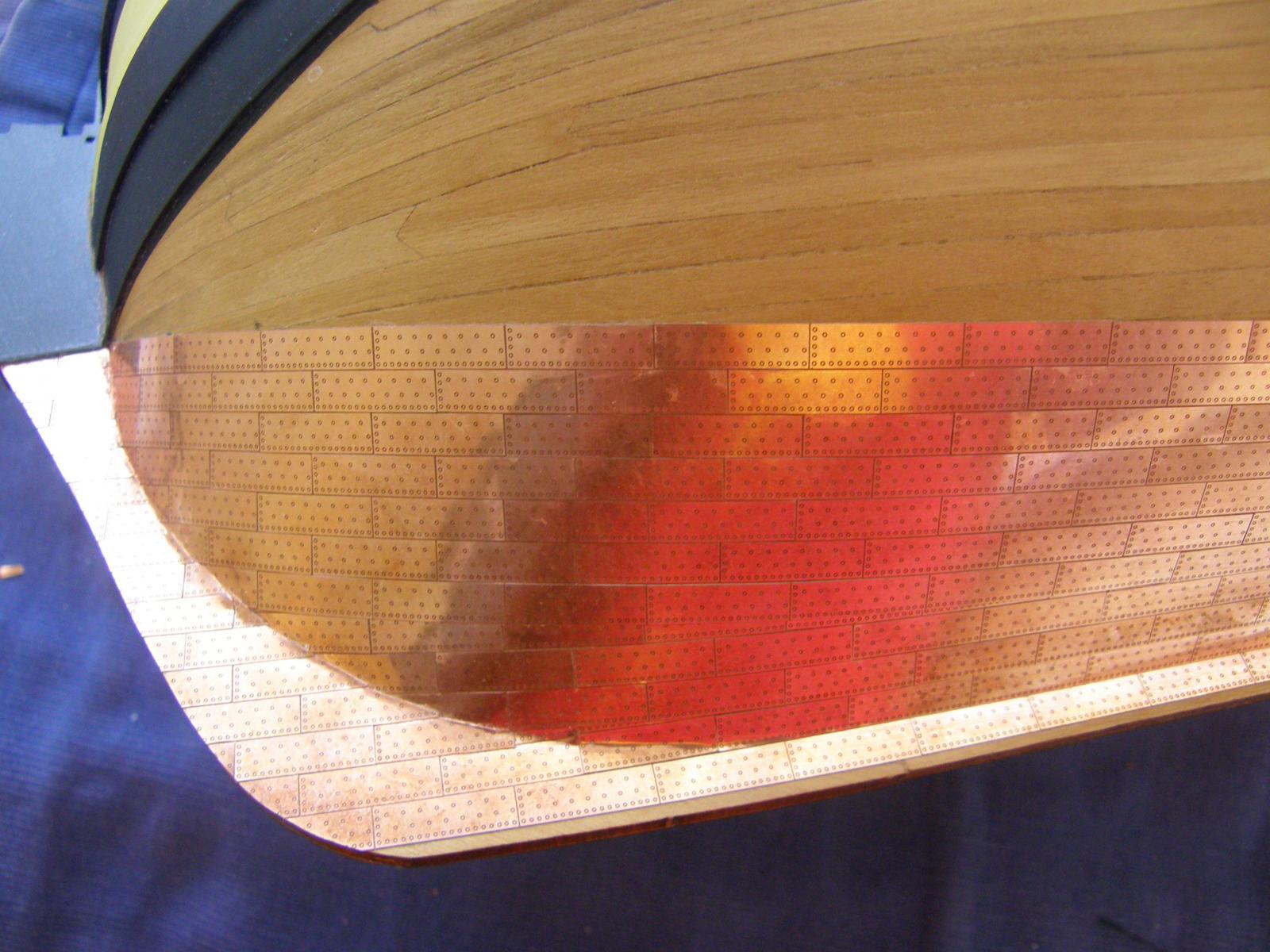
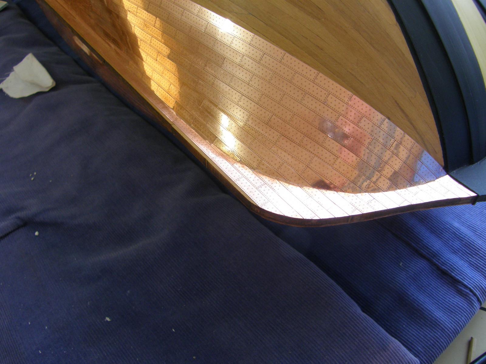
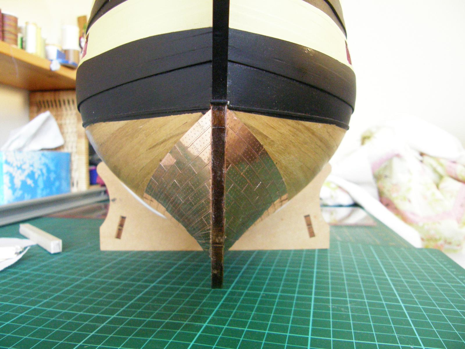
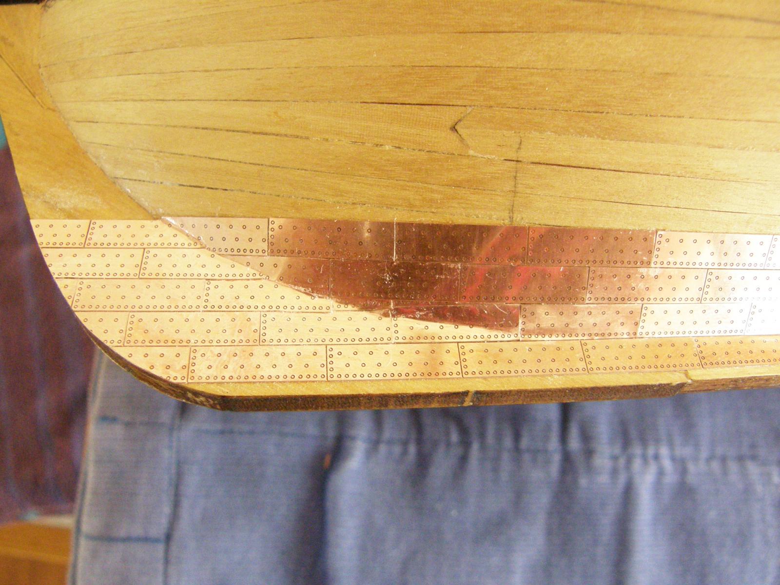
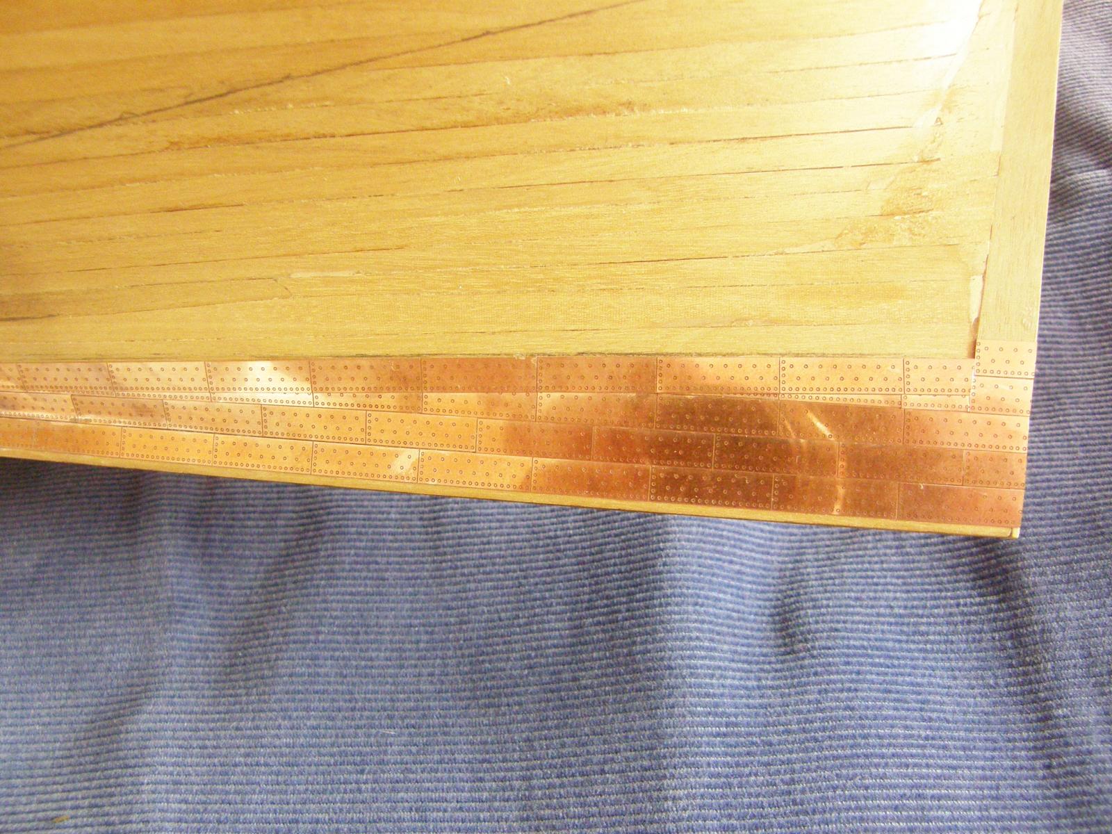
Here are shots of the the coppering (finally ) to the waterline. Aside from completing the other side, I still have to take to copper to the bottom of the keel (about 2mm). I haven't yet decided how to do it. Starting where I did - just hitting the garboard strake - seemed like a good idea at the time.


-
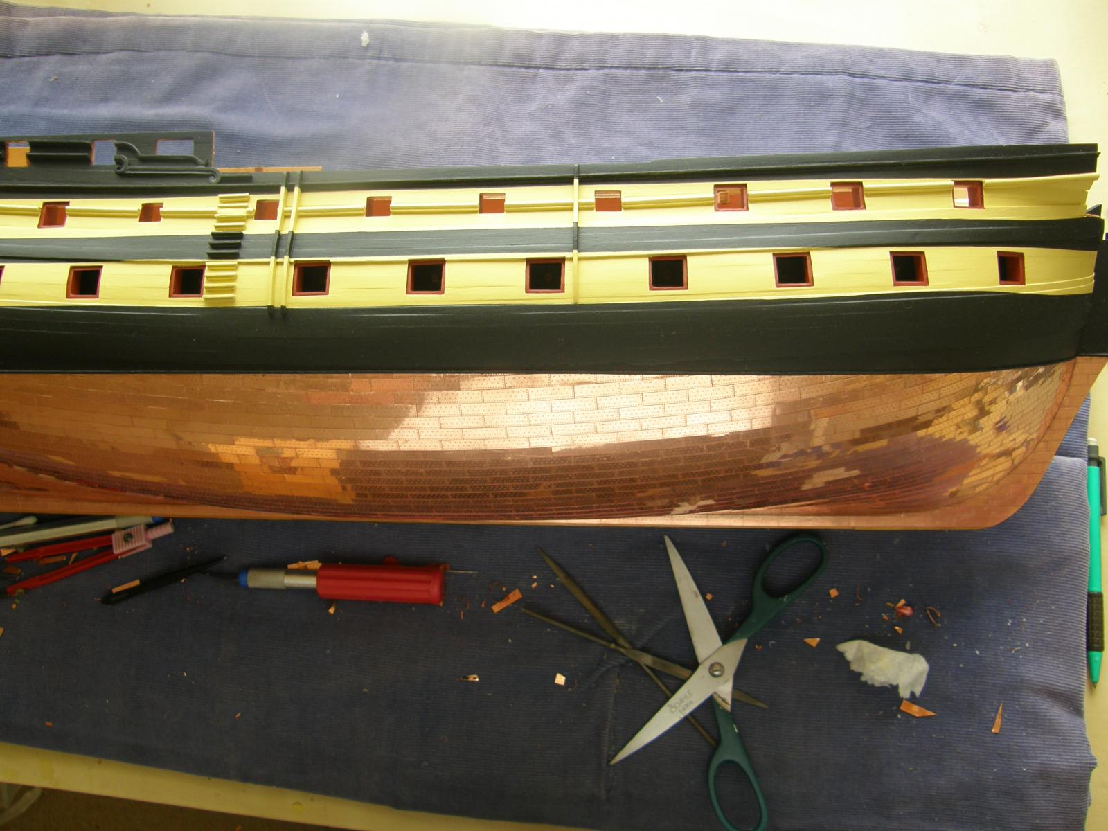
The coppering is proceeding - slowly. I am getting to the stage when I am unable to apply the full seven-plate strips. I can see that as I approach the waterline it will be possible to apply fewer and fewer in strips. Nevertheless it has worked out well and has enabled accurate laying of the plates until the layers hit the waterline at the stem and the stern. Now all the rest should (?) fall into place so that both sides of the coppering are symmetric. Well, as earlier wrote - that's the theory.
I have made an incidental discovery too: in getting rid of tarnish, rubbing a piece of lemon seems to work as well as the salt, carb soda lemon mixture.
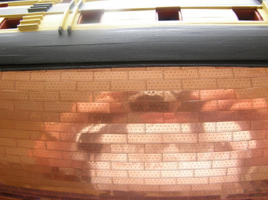
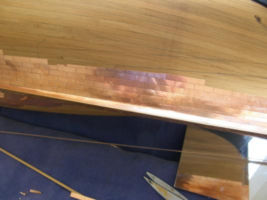
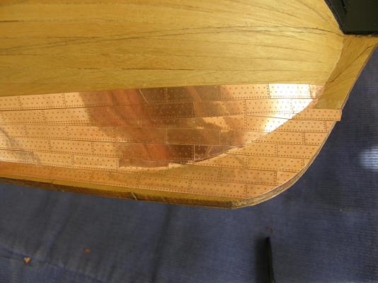
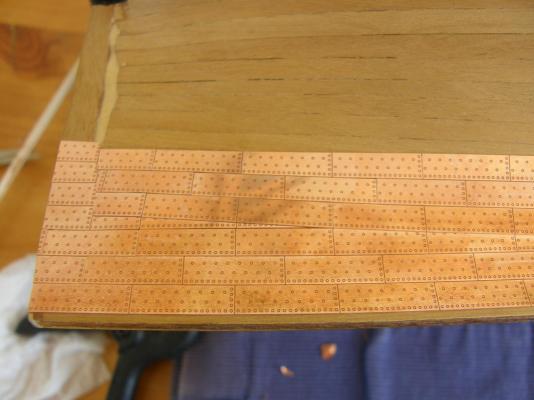
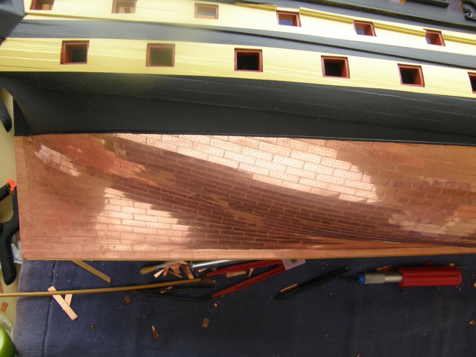
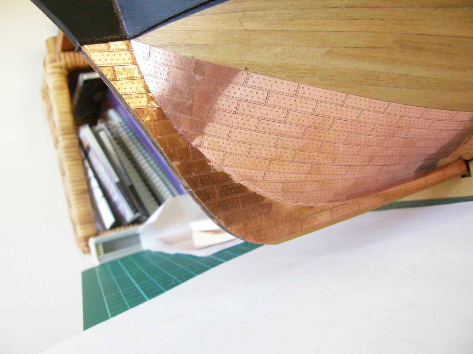
The following 4 photos take the copper up to the waterline at the stern.

The following show progress to date.


The first couple of rows before and after reaching the waterline proved to be quite difficult. Both trimming and curving the plates at the stem and the stern were a bit of a pain. In one or two cases it took nearly hour to get the right shape and then to attach it. My vocabulary was fully tested.


-
Many of the plates have been badly and unevenly tarnished so I have cleaned them up with the lemon juice, salt ,carb soda mixture I mentioned earlier. When I have finished the coppering I will cover it with matt polyurethane spray.
-
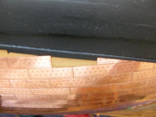
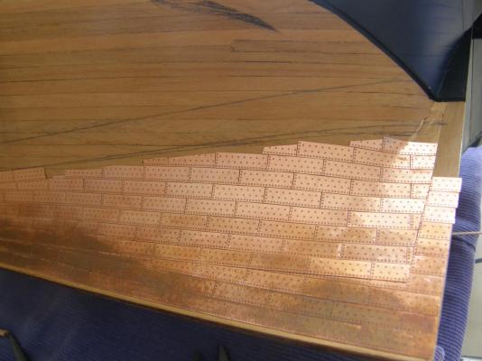
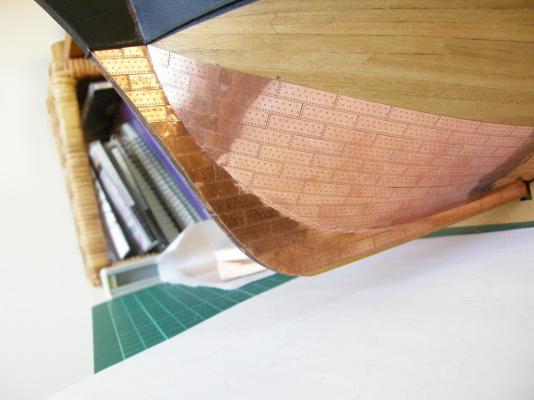
I have finished the stealers at the stern I hope. In the following photos I have tried to show how I have gone about it. The following two photos show laying the first of the rows of stealers which will then be overlaid with a full seven-plate strip.
Here is the overlay applied.


Now the next four rows of stealers.
This is the way I have applied the CA to the seven-plate strip. It ensurers the edges are covered.
The strip applied.

-
Chris: unfortunately I don't have a polarizer, but I have started using the "beach" and "snow" settings on the camera. Both seen to make some difference.
Bob
-
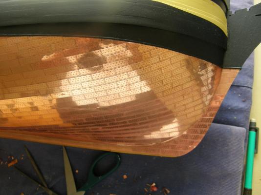
I hope that the hard part has been done now that the plates have been laid to the waterline at the stem. My theory is that when I get to the waterline at the sternpost all the rest of the plates in between will fall into place. Well that's the theory anyway.


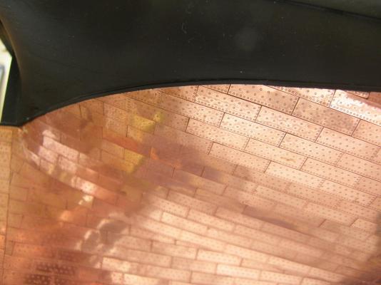
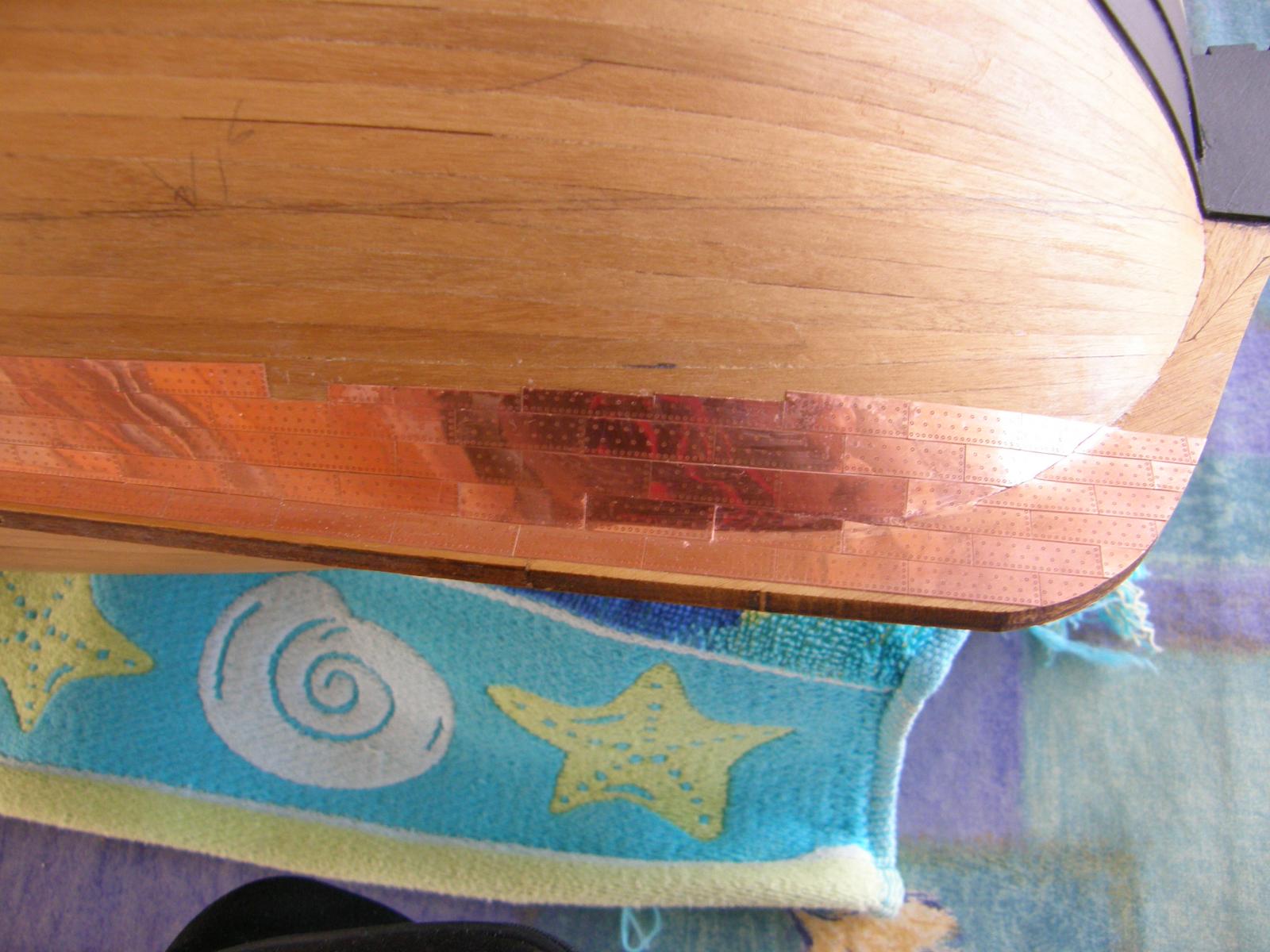
The marks on the next two photos are reflections and the apparent gap shown in the last of these pictures is also non-existent.

-
BE:
I have been cleaning off the CA with acetone, more or less as I go, though I am sure I have missed a few spots. Once I finish the coppering I will go over the entire job to pick up any survivors. I have found that in a couple of instances where the CA is stubborn, a drop of CA debonder does the trick.
The CA I am using stays in place and in the main, doesn't end up where you don't want it.
Bob
-
I have found an excellent concoction for getting rid of the tarnish on the copper. Despite misgivings regarding the use of salt, I tried the following mixture. Lemon juice, bicarbonate of soda, and (a little) salt. Rub on with a soft cloth, wipe off with a wet cloth and the copper come up beautifully, leaving the etched rivets unaffected.
-
Jason: thanks for the comments.
Yes, the strips work well, and I certainly recommend their use. I began laying the full strips of seven plates from the centre of the hull and worked forward and backward from there.
For the stealers, as I approached the stem (in particular) it was sometimes necessary to correct for the curvature of the hull by laying strips of fewer than seven (I tried to lay as many as possible in a single strip) and at the stem I generally laid only a single plate to obtain the correct curvature. I used a pair of sharp, heavy scissors to approximate the curve and filed it to final shape using a dremel abrasive wheel. It may not be obvious, but where there is curvature and two strips had to be joined, I filed the edge of the new strip to minimise the gap between the two strips. As well, it was sometimes necessary to file (using the dremel again) a tiny fraction off the lower middle of a plate to make sure the new set of plates fitted snugly to line of plates below it.
Once the stealers were in place, I overlayed them with full, seven-plate strips to the stem and to the stern post. And then started the whole process again ....
I used Selleys Quick fix CA gel. It stays where you put it and is 'repositionable' - though you still have to be quick. I found ZAP gel just a bit too quick.
I hope this helps.
-
Brian and Arthur: thanks for the kind comments.
As you can probably see, as the process went on I got a bit better at it. The temptation is to redo a few bits, but fortunately I think I can resist. If I ever do another coppering at least I will have learned a few lessons.
-
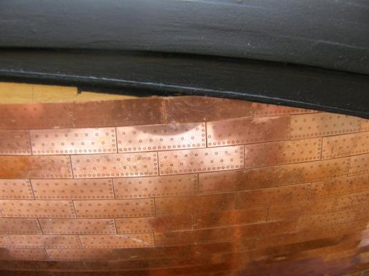
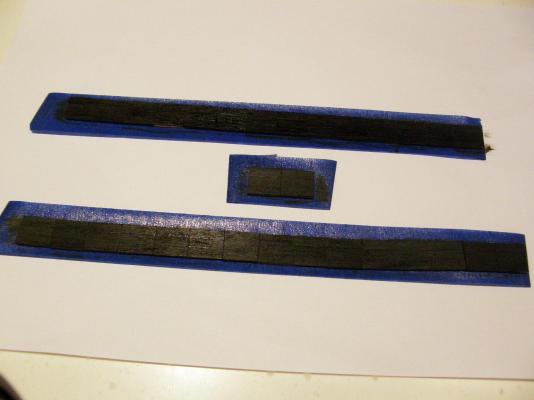
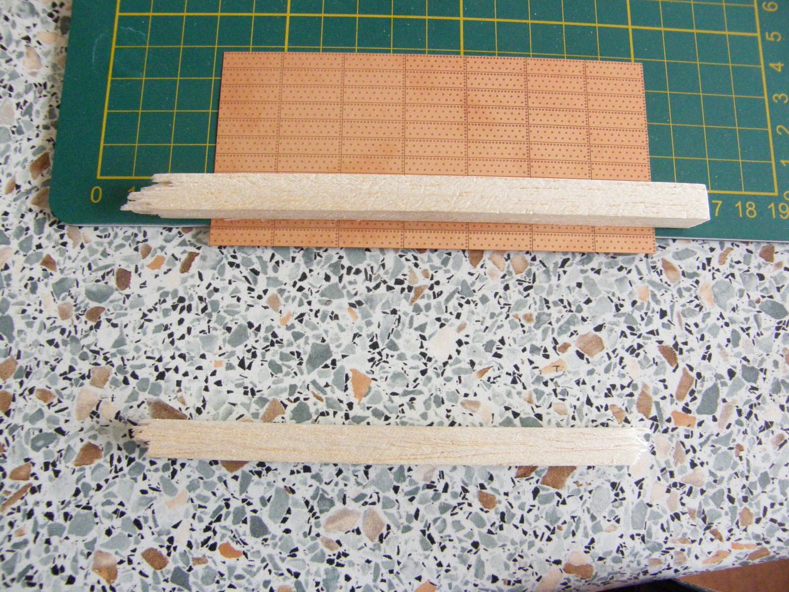
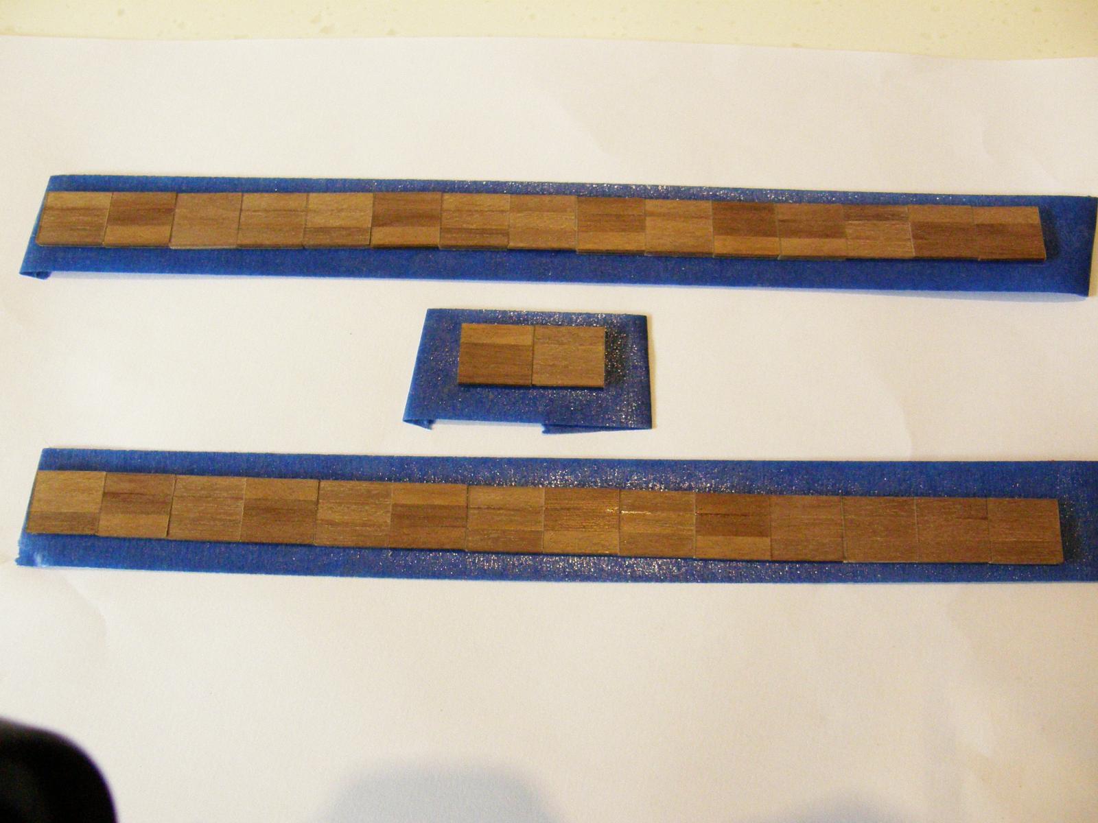
I have made fair progress on the coppering. As I earlier wrote, wherever possible I have attached a strip of plates rather than singles. I was concerned however, that the strips would be damaged in the process of breaking. The following method worked quite well. The strips were broken off using two pieces of balsa: one on top of the set of plates; the other applying pressure to the strip to be broken off.
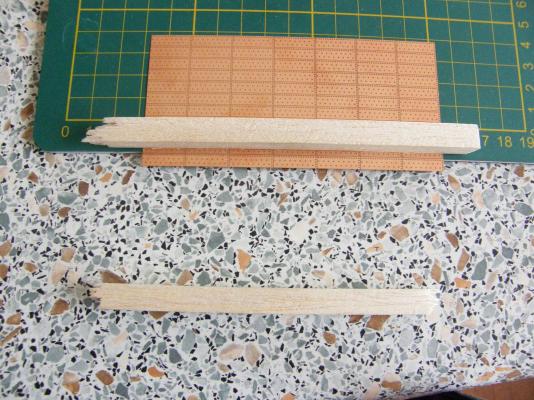
Here are some pictures of progress.

Like Mitsuaki, I have overlapped the plates where stealers are necessary. This shows some trimmed plates that were later overlapped by a full strip of seven plates.

I have concentrated on the bow which I have found so far to be far more difficult than the stern.

The apparent gap shown in the photograph below between one of the plates on the hull and the corresponding plate on the stem is just a reflection. Photographing the shiny plates without reflections turned out to be a bit difficult.
- The Sailor, Blue Ensign, mort stoll and 1 other
-
 4
4
-
-
Arthur: it is quite difficult to see just what is happening on the Cutty Sark photo. It does seem to me that the line of plates XIX does have the ' Watton orientation', but the rest of it looks like a bit of a dog's breakfast. I suspect that whoever did the rivets did it whichever way seemed to do the job. You just can't get good help these days ....
-
I have finally started coppering. So far it has gone well - which of course is likely to be an invitation to future disaster.
I have followed Mitsuaki's method of overlapping the plates where stealers are necessary. The results are very good indeed. Incidentally I have followed the orientation of the plates according to the kit instructions. I contacted Chris Watton regarding the issue, and he was adamant that the line of 'rivets' should be at the bottom and the verticals should face the front.
Wherever possible I have applied the plates in strips rather than individually - using gel CA. Acetone takes off any unwanted glue easily. Laying the plates over the transition from the curved part of the hull to the stem has turned out to be the most difficult. Getting the correct curvatures to the plates is essential. Here is the procedure I used.
First, the transition plates were trimmed to approximate curvature (one on the hull; one on the stem), so that when the plates were bent, there was a slight overlap of each plate between the curved part of the hull and the flat of the stem.
Second, CA was applied to a part of each plate that did not need to be bent.
Third, the partially glued plates were stuck on to the appropriate places. The first one on the hull; the second on the stem. Partially sticking them on meant that when doing the bending, the plate would not move, and the bending could be done 'on site' with accuracy. I used the sharp end of a bamboo meat skewer to apply pressure to make the bends - worked a treat. Once both plates were bent to the correct curvature (the plate on the stem to very slightly overlap the plate on the hull), ordinary thin CA was applied so that it would seep under the unglued parts of both plates, securing them both. Any unwanted CA on the plates was cleaned off with acetone. The result (so) far has been a nice, cleanly defined curve.
Describing the procedure has proved more difficult than I thought. I hope it makes sense and is helpful. All going well I will retrieve my camera my camera next week and will try to illustrate the description.
-
I have just lost a couple of paragraphs. Presumably they are in the ether somewhere. It's VERY annoying.
I have finally received the extra bed for my Proxxon lathe. It increases the length of the bed from 250 to 500mm, though the full 500mm is not really usable.
With it, I have rectified the problem with the over-diameter main mast (see above). I reduced the diameter below the top boarding pike ring by a little less than 1mm. That ring now fits snuggly up to a very small step in the diameter of the mast. The difference in the two diameters above and below the ring is obscured by the ring itself, and will be completely unnoticeable once the pikes are in place.
The length of the mast is 455mm and this, I suggest, is the extreme length that could be handled by the extended bed - and only because of the thickness of the dowel (12mm), the use of the slowest speed of the lathe, and the work area being close to the chuck (which gave the dowel good support). For most purposes about 320mm would see it out.
At the moment my camera has been pirated by a certain member of my family and I won't have it back for a couple of weeks.
If anyone is interested in the lathe setup, or what the mast now looks like, I will post a few photos when the camera returns.
-
Arthur: it's amazing what 3 weeks or so away will do - I did realise that the topmast would not fit though without the two-piece cap, but it had slipped my mind. Jet lag of course, though age may have something to do with it.
I won't have much time to play with it until some time next week (I have some heavy duty gardening to do), but will try to make sense of it when I get a chance.
-
Arthur: lucky you on receiving two lengths of dowel - not that I'm bitter.
The cross-sections certainly make no sense at all. Aside from anything else, if you compare the corresponding cross-sections for the foremast and the main mast, they are identical.
The caps for the foremast and the main mast provided in the kit are both in two parts and I have just followed their example (it also makes it easier to make a nice, clean, square hole). I had assumed the two piece setup would make it easier to fit the topmasts - but now that I look, the cap for the mizzen is a single piece....
The blocks (T) are a complete mystery to me too. The master master is Blue Ensign (BE) and he may be able to help.
On the preceding page there are some pictures of my (almost) complete foremast - with cheeks, but so far, no hounds. I ignored the cross-sections on the plan. I made the flat portions of the mast to receive the cheeks by tracing the outline of the cheeks on the mast, then used the same method of making saw cuts to the appropriate depths, chiselling out the cuts and filing the rough to finish. (The tops of the cheeks have the same measurement are the square section of the masts above them (8mm in the case of the foremast)). The method is the same as I have shown in creating the square sections of the mast. If a closer picture of the fitted cheeks would help you, let me know.
I have delayed fitting the hounds as I would like to get an idea of the the rake (if any) of the masts - as the crosstrees have to be parallel to the waterline.
Finally, I cannot see why the square sections at the bottom of the topmasts are completed with a square section of 5x1mm walnut. Why not simply square the dowel to the appropriate dimension? I suspect all of this is part of a cunning plan to drive us all mad. As far as I am concerned, so far it's working a treat, though my wife has just suggested (somewhat unkindly I think), that I already had a good start.
-
I have not had this problem with walnut from Amati. On the odd occasions I have had your problem I have sanded the edges by putting a sheet of 400 glass paper on a bench then pulling the piece of strip edge-down across the glass paper a couple of times - first from one end, then the other. It will usually give a good finish to the edges.
Colour is a matter of taste, but most of the walnut I have worked with has not been especially dark.
All the best
Bob (RMC)
-
I have just begun the gun port lids - have cut them out and began their painting - as a quick job before going away tomorrow.
Parts 64 and 65 - the backing for the lids - are not long enough to take account of the material lost in the process of cutting the segments into their correct lengths. It's rather annoying, but there is sufficient scrap ply to make up the shortfall.
Once the lids were cut to size I lined up all the lids on masking tape (no gaps between them) and painted their fronts black all in one go. It worked a treat and has given them all a really good finish. I will do the same with the red specified for the back of the lids.
Here are the lower lids lined up ready for painting.

and here , after 3 coats of paint. A 4th coat was added after this picture was taken. A couple of coats of Estapol matt will fininish them off nicely.
Back in about 3 weeks to begin the coppering - something I am dreading.
- fake johnbull and mtaylor
-
2
-
Len: I had thought of taking the 5th. But I thought an early guilty plea may bring clemency. I can only stand so much pain.
Bob
-
Mitsuaki: Before making your masts, make sure the boarding pike rings fit. See my latest post.
Bob (RMC)
-
Len: before making your masts, make sure the boarding pike rings fit. See my latest post.
Bob (RMC)
-
I have just made two unpleasant discoveries regarding the fore- and main masts.
1. The rings for the boarding pikes do not fit over the lowest wolding on the foremast. I will have to take it off and redo the wolding after the upper ing is fitted. I suggest anyone who has not begun the masts keep this in mind.
2. Worse, the 12mm dowel for the main mast is very slightly over size. I did known this but as the difference in size was (I thought) trivial I simply gave it a final sanding and proceeded to put 3 coats of paint on it - before I realised there may be a problem (in fact two problems). Naturally ignoring the oversize has come back to bite me: the rings do not fit. Again, make sure the rings will fit after painting. In the case of the main mast at least, the rings do not need to go over the wolding.
Turning the main mast to the correct specification is going to be a bit of a problem as it is already shaped at the top: ie a square section. One solution is to turn the mast to the correct dimension to the point where the upper ring fits, and leave the rest of the mast as is. The difference should be disguised as it will be covered by the boarding pikes. Anyway, I'll see how that goes before further panicking.


HMS Vanguard by RMC - FINISHED - Amati/Victory Models - scale 1:72
in - Kit build logs for subjects built from 1751 - 1800
Posted
Hi Wackowolf. A belated thanks for your encouragement. I have just had a note from Fake John Bull (Mitsuaki) explaining how he covered the lowest 2mm of the copper to the keel. I hope I may be able to finish the coppering in a week or so (other things intervene) and will then update the pictures in my log and try to describe how things went.