
HOLIDAY DONATION DRIVE - SUPPORT MSW - DO YOUR PART TO KEEP THIS GREAT FORUM GOING! (Only 13 donations so far - C'mon guys!)
×

alross2
-
Posts
408 -
Joined
-
Last visited
Content Type
Profiles
Forums
Gallery
Events
Everything posted by alross2
-
 OREGON 1893, WYOMING 1909.
 -
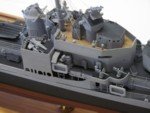
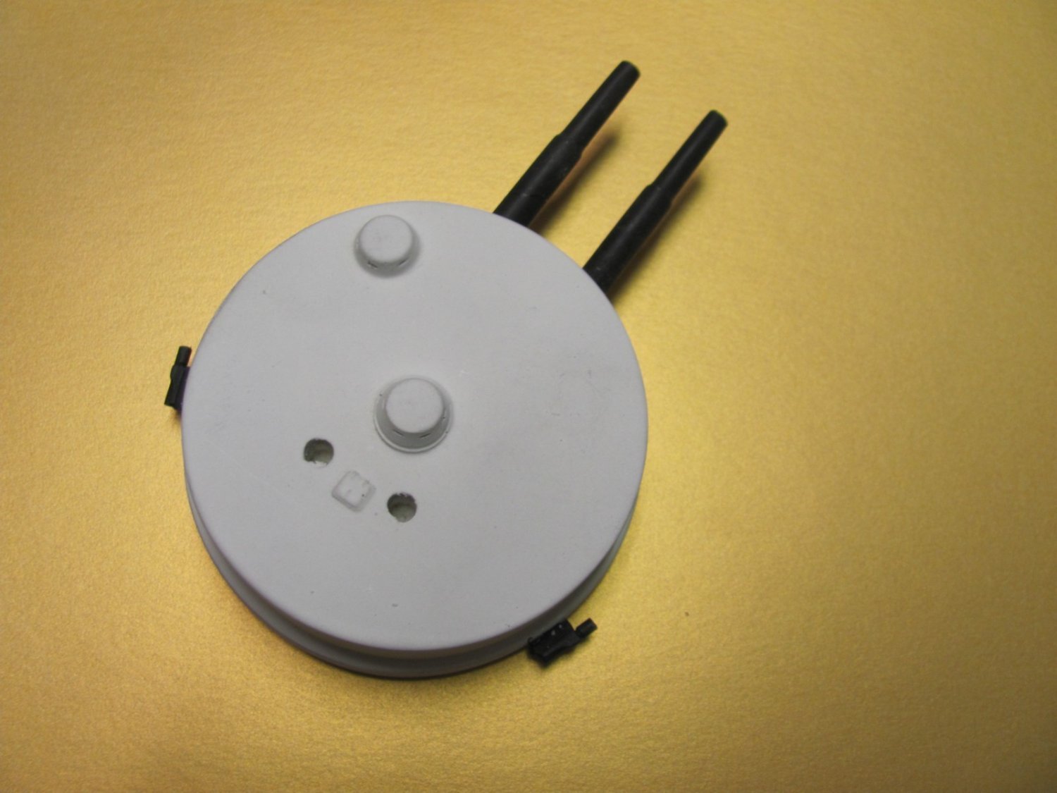
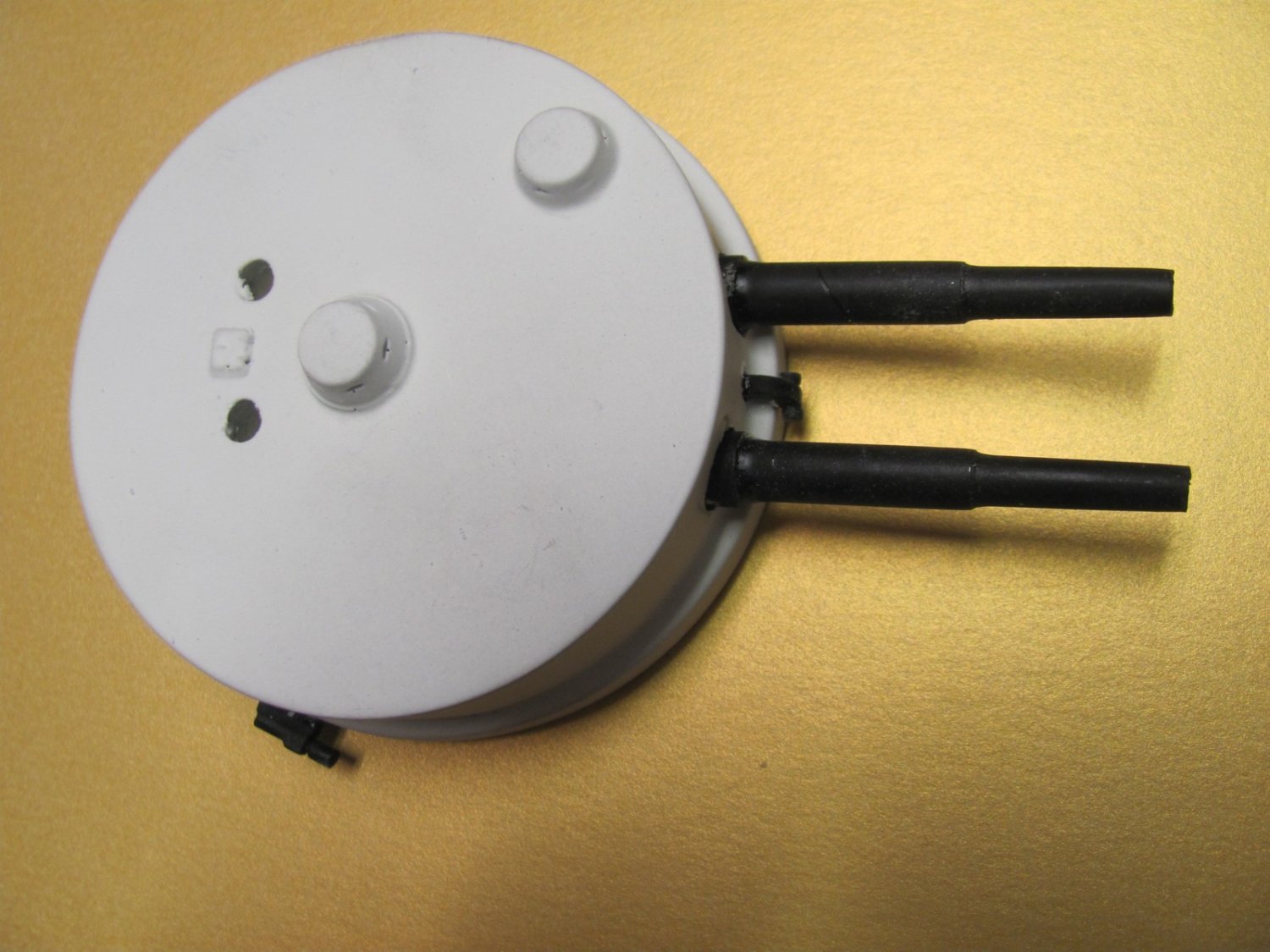
13" turret showing black limit stops. Two short cowl vents will go into the holes in the turret top.


- 194 replies
-
- 12
-

-
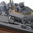
OK, WYOMING is going to Nic for rigging, so I'm back full-time on OREGON. Today was mostly printing out plans and parts lists and getting my head back into OREGON. Painted up a bunch of castings and started applying the photo-etched 6" casemate doors. There are five doors on each casemate, which is curved, so it takes a while to get them lined up.
- 194 replies
-
- 10
-
-
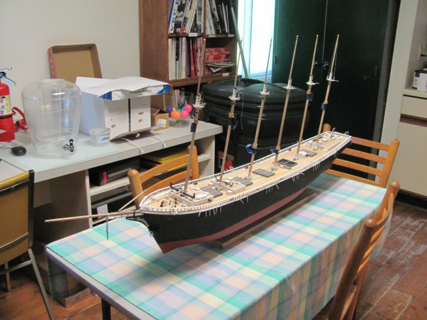
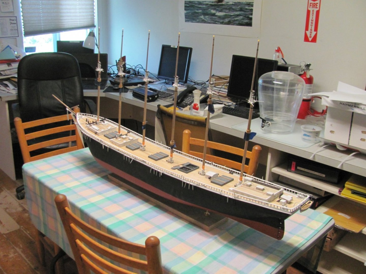
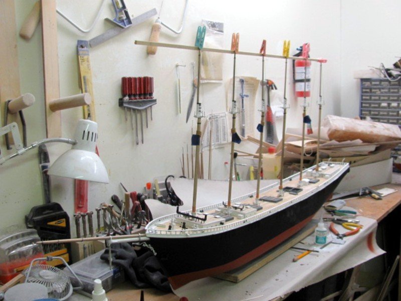
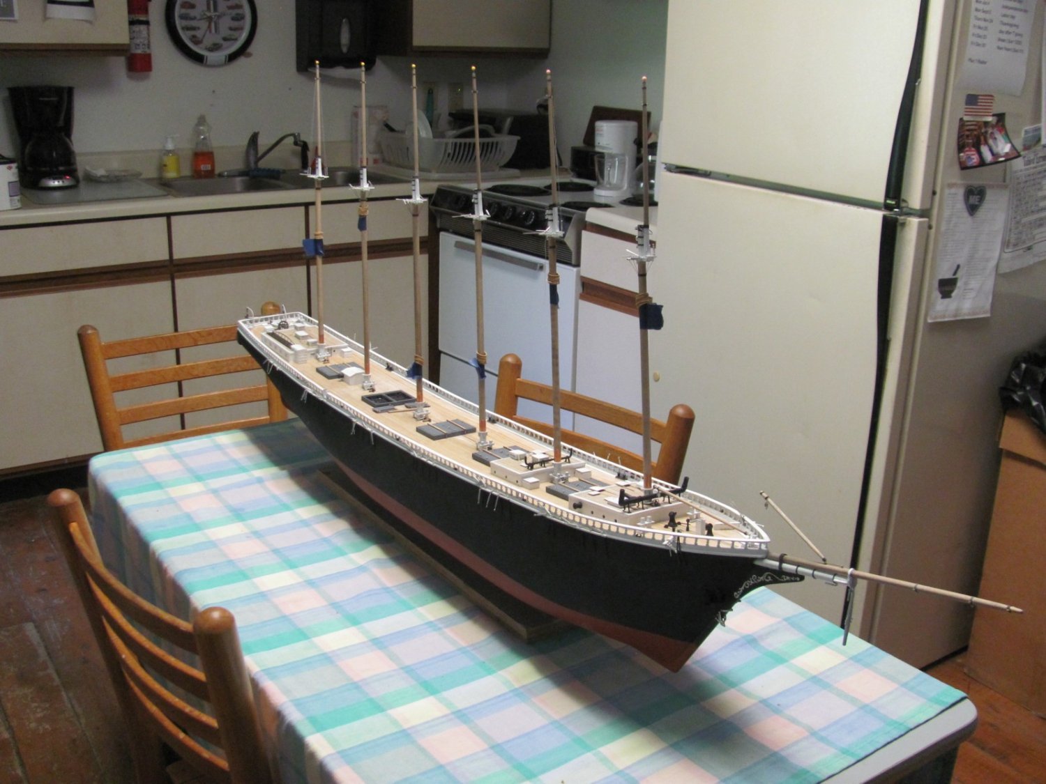
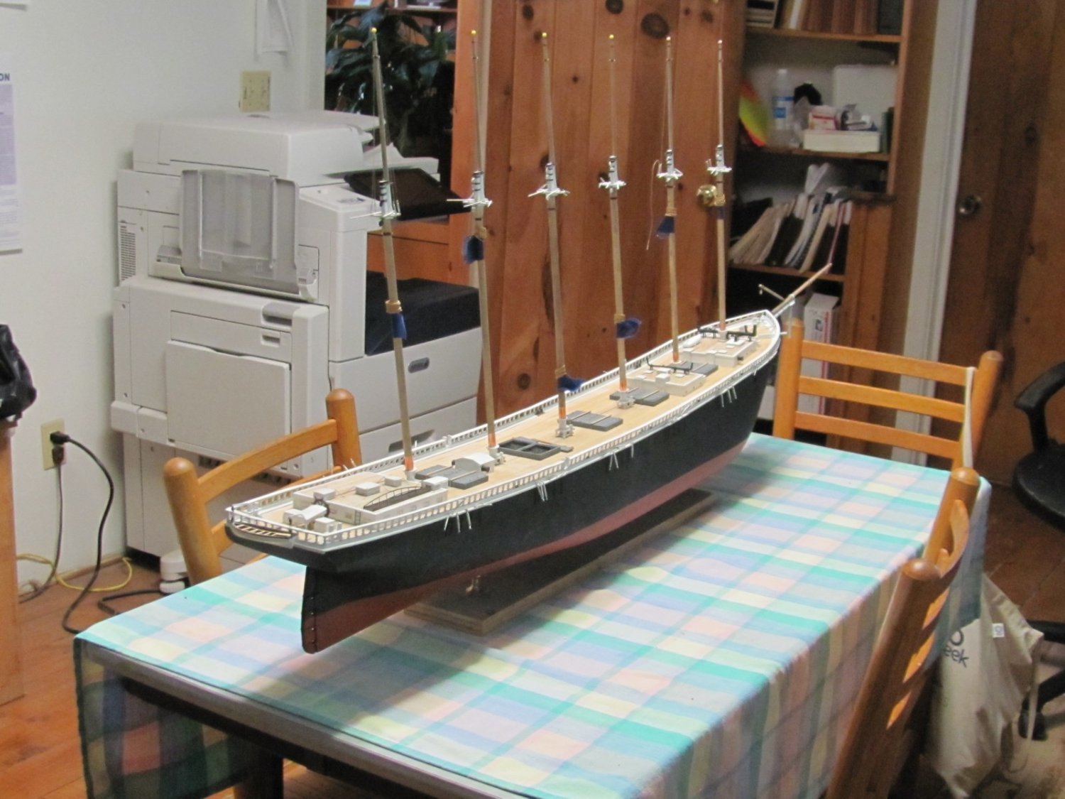
OK, I'm done building WYOMING. It's now over to Nic to rig her (I hate to rig!). Once he's finished, I'll do any necessary touch up and ensure the rigging plans and the model rigging match. After that, she'll be in production. That table, BTW, is 48" long.


- 194 replies
-
- 14
-

-
-
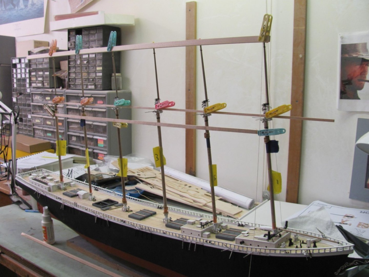
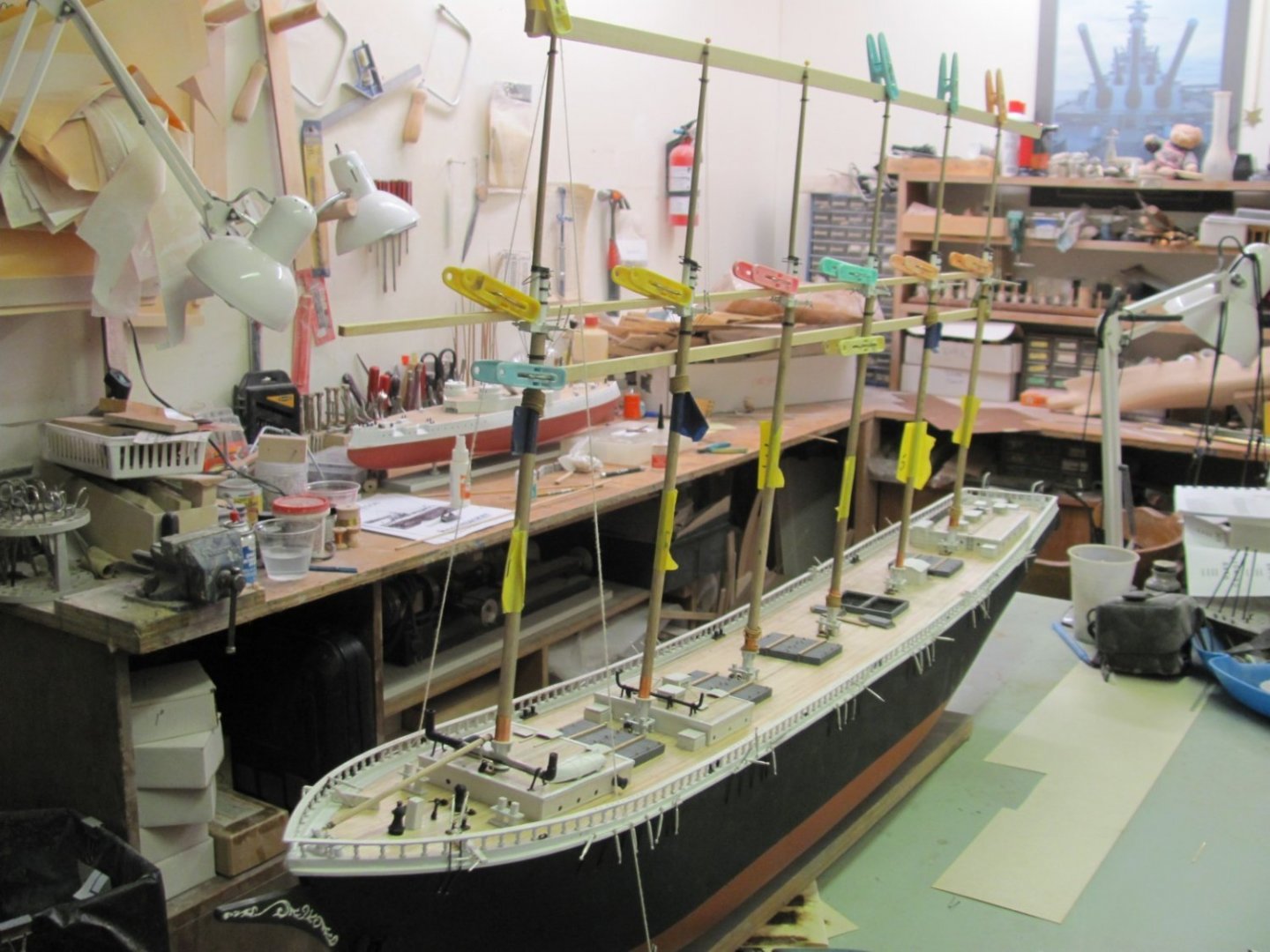
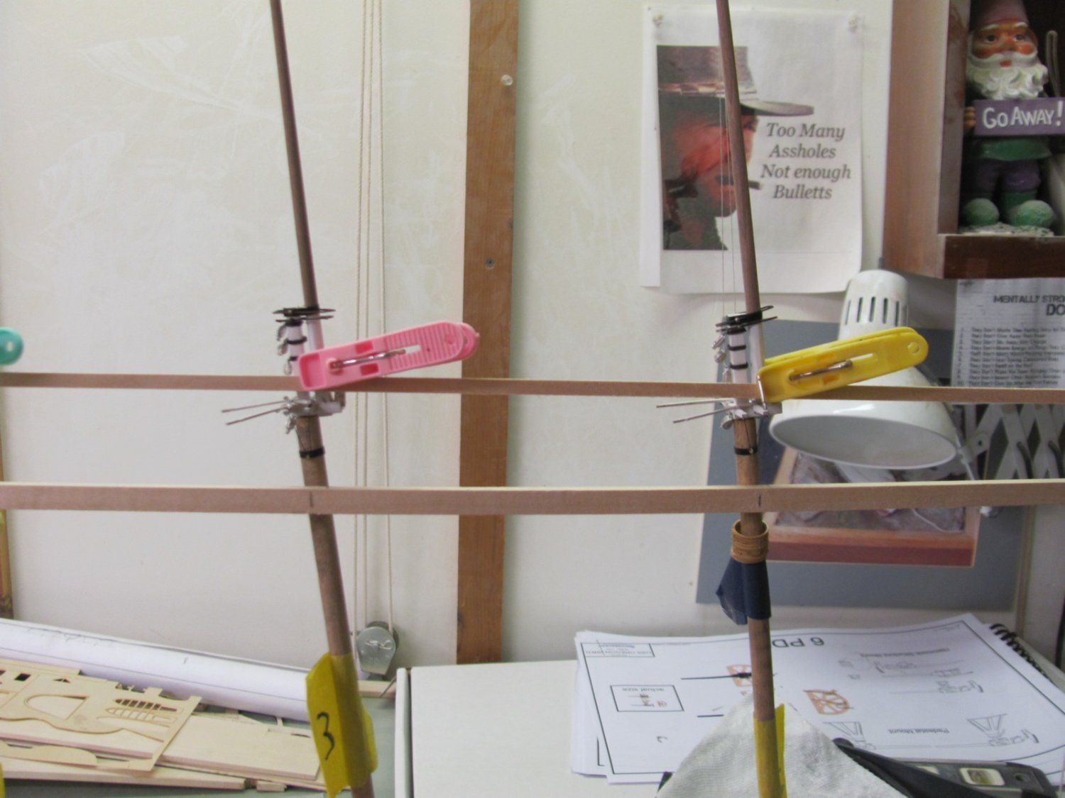
Aligning the masts. It's a simple approach but works well. The forecastle mast was set at the correct angles first, then the rest of the masts were aligned with the distances between them at the boom jaw rests. The clamps keep everything aligned while a drop of glue sets the angles.


- 194 replies
-
- 11
-
-
-
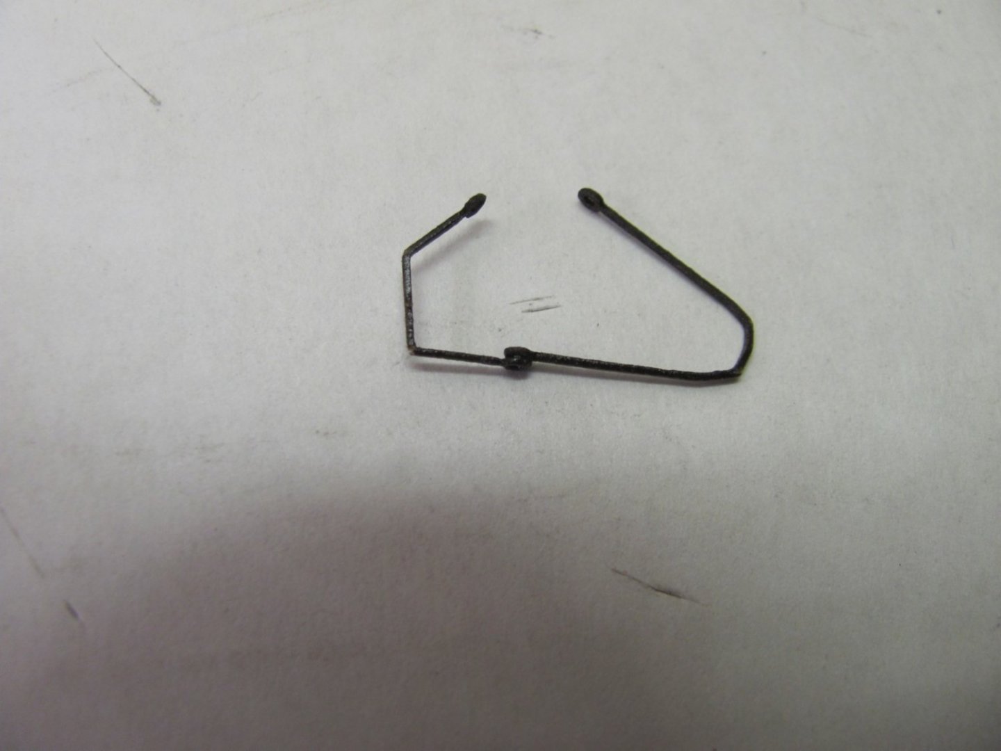
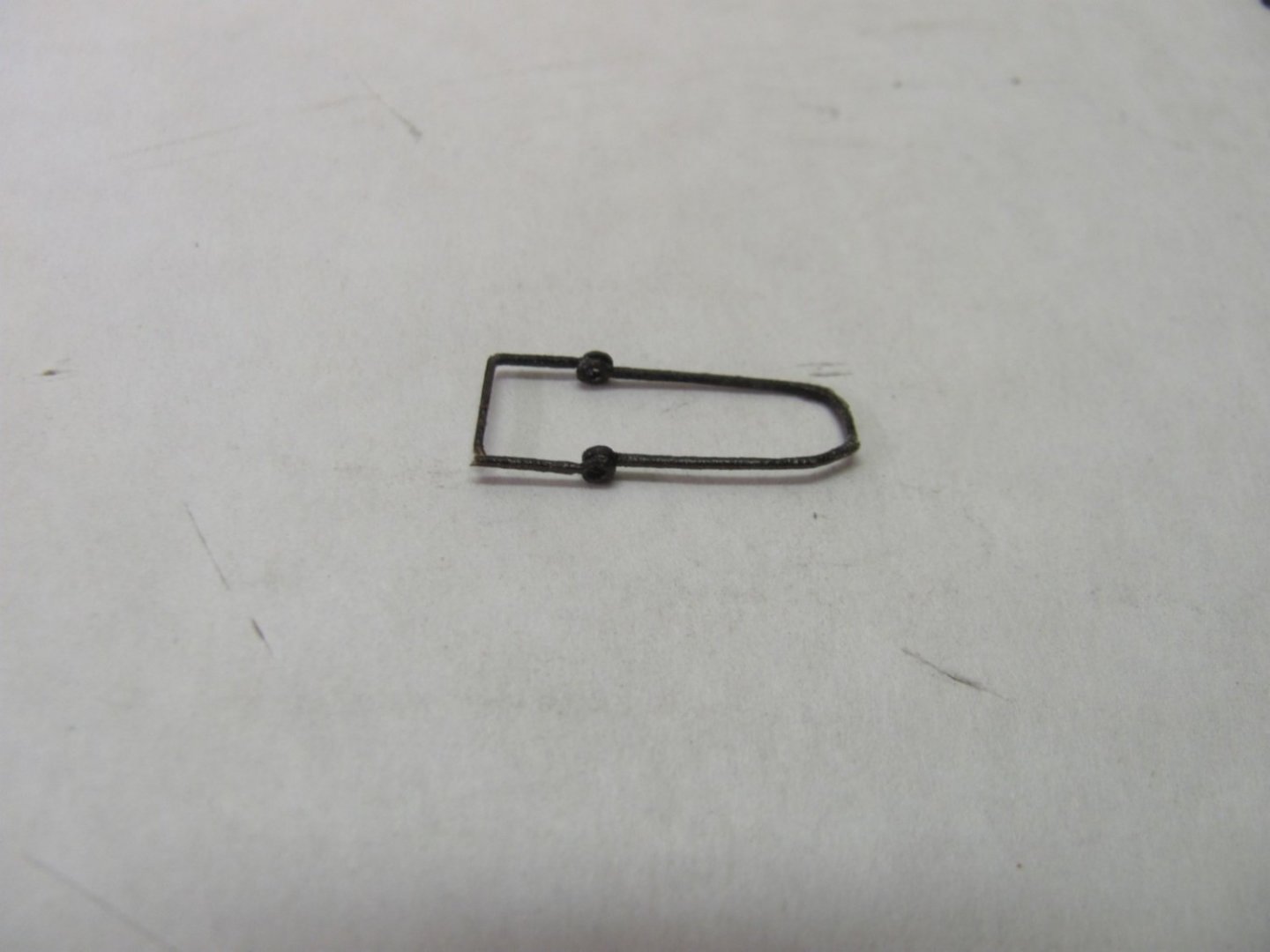
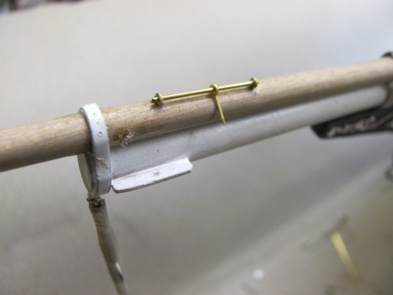
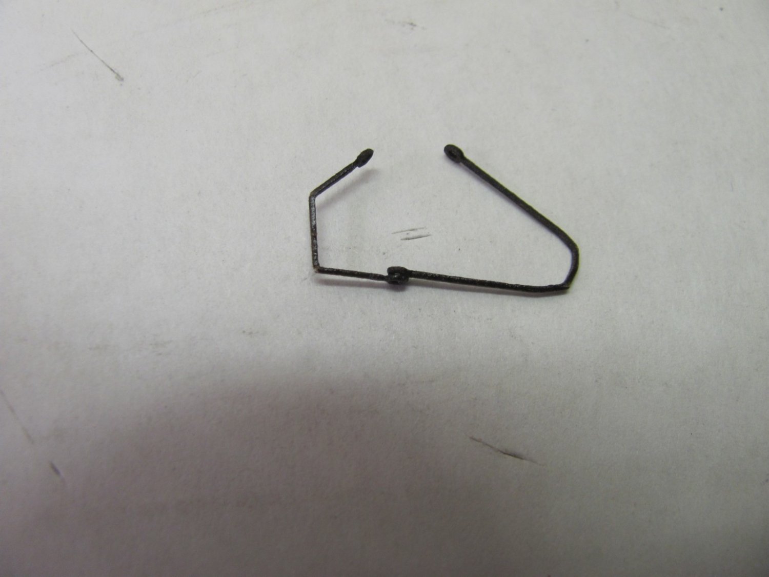
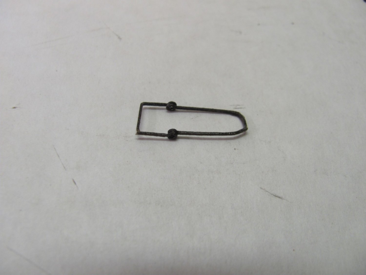
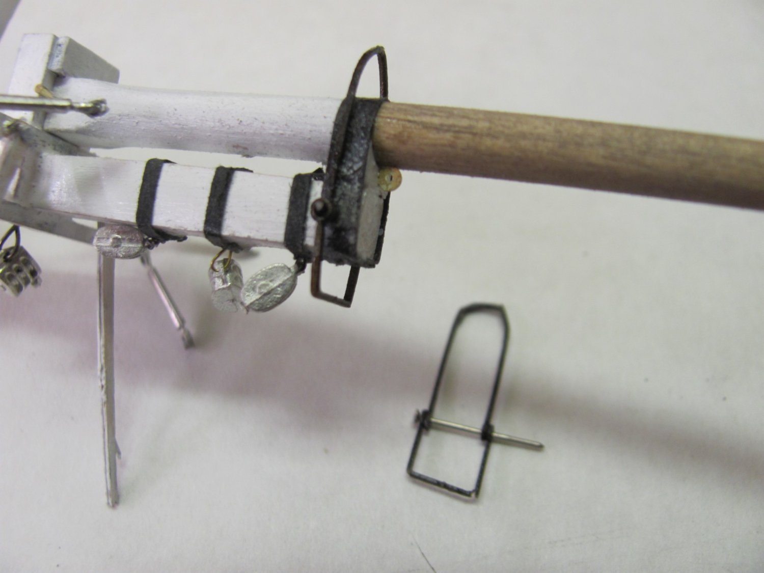
The spring stay bails require a little patience and care to build. They are laser-cut .020" laser board but are surprisingly strong and flexible. They are best built off the mast. Two eyes are glued together, a light coat of thin CA is applied to them, then they are bent over a dowl (front bail) and 1/4" square stick (aft bail). The mast is drilled with a .022" bit, the bail is slid down over the mast, and a pin goes through the holes. Once everything is aligned, CA is applied to the end of the pin and the end is snipped off.

- 194 replies
-
- 11
-
-
-
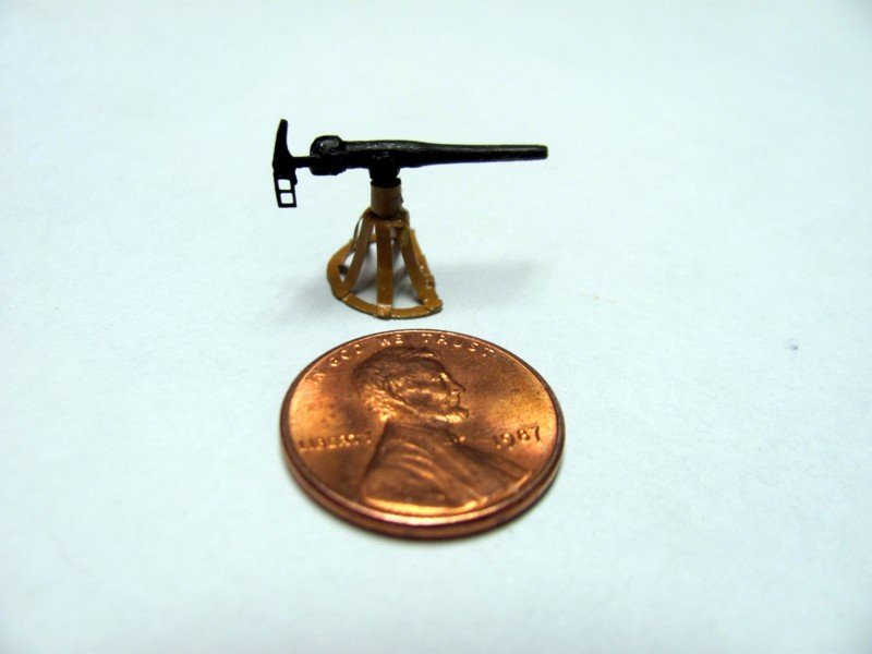
While I'm waiting for some new rigging line for WYOMING, I'm back on OREGON. Painted up one of the 1 pdr guns.
-
Never mind. I just read an earlier thread on the subject. Should have done so before asking...
-
What is the actual vertical distance between ratlines on a 19th C sailing vessel? I'm thinking maybe about 9".
-
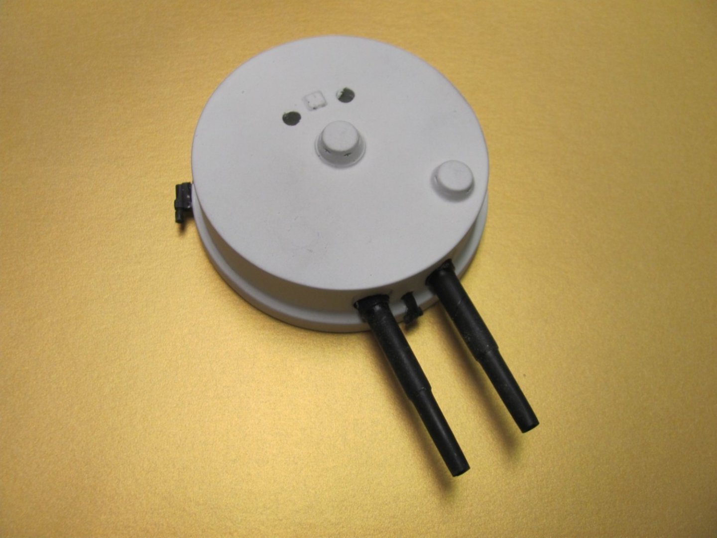
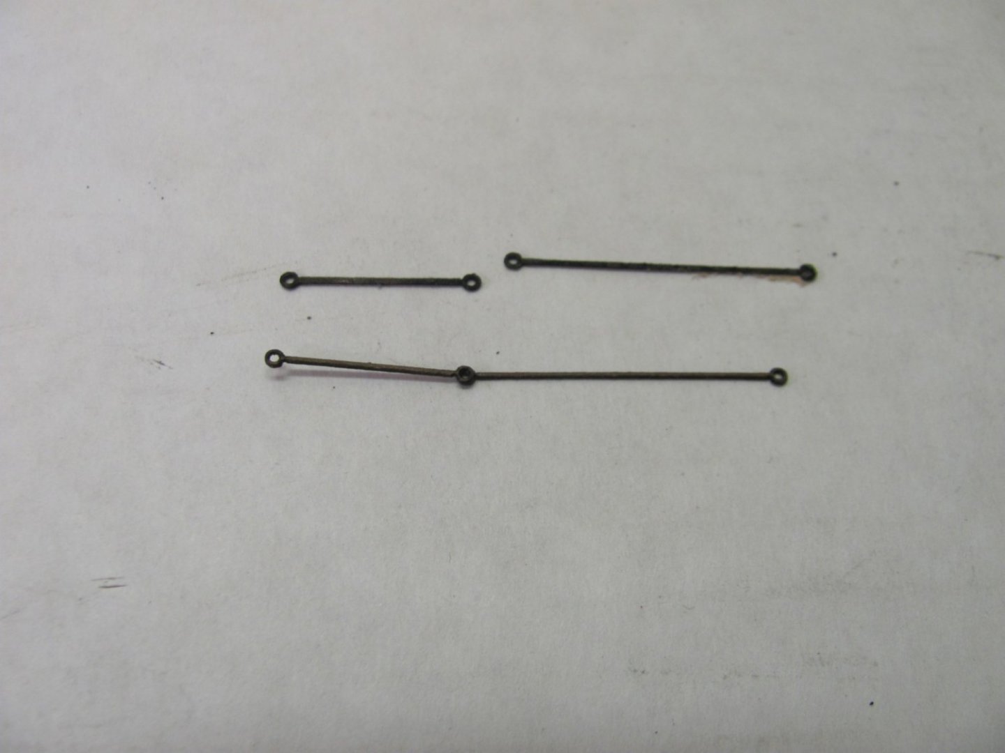
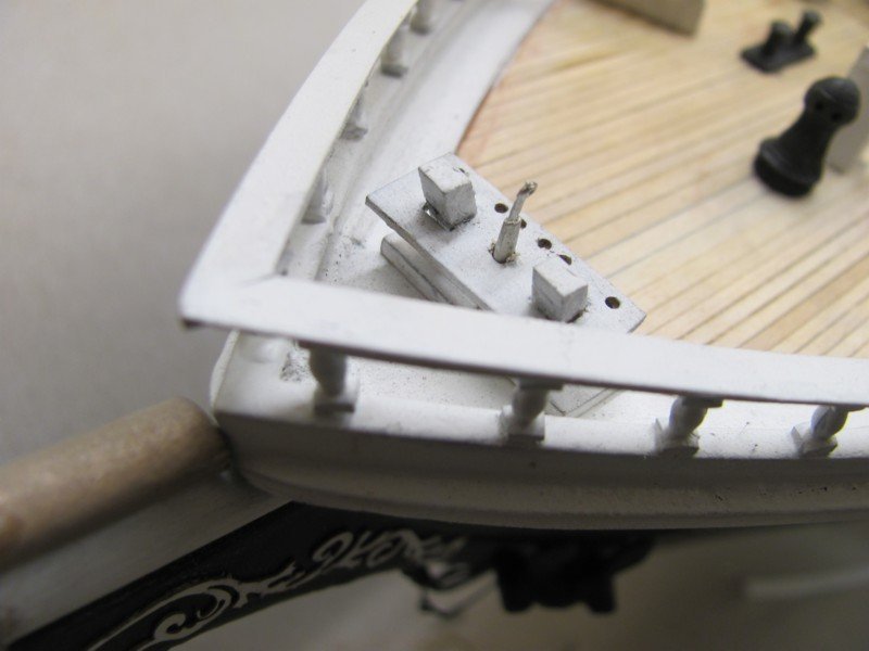
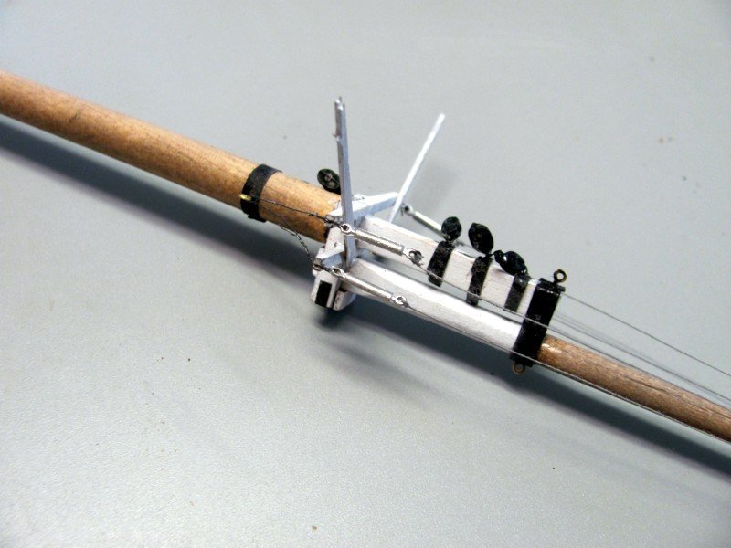
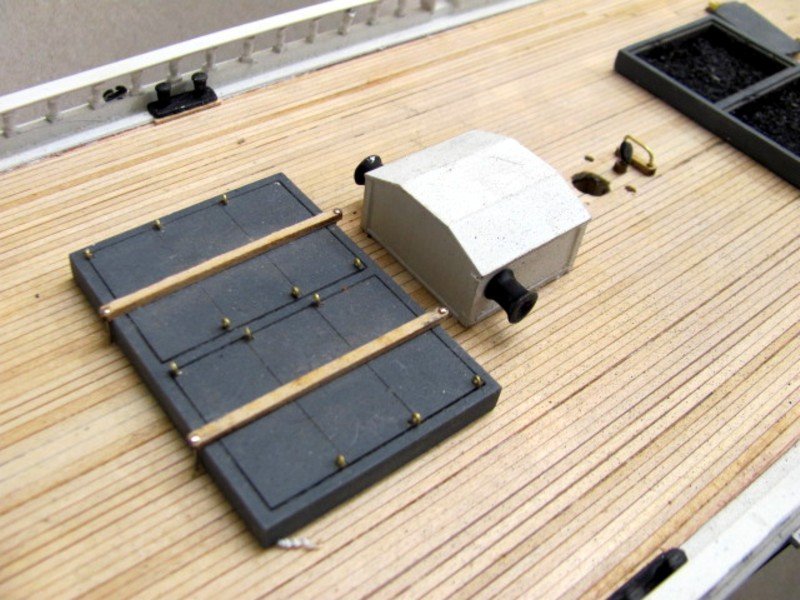
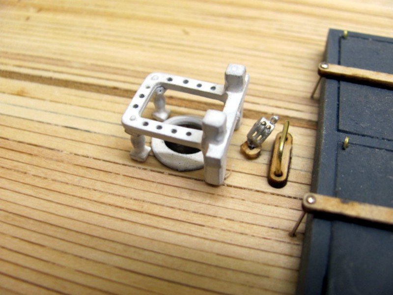
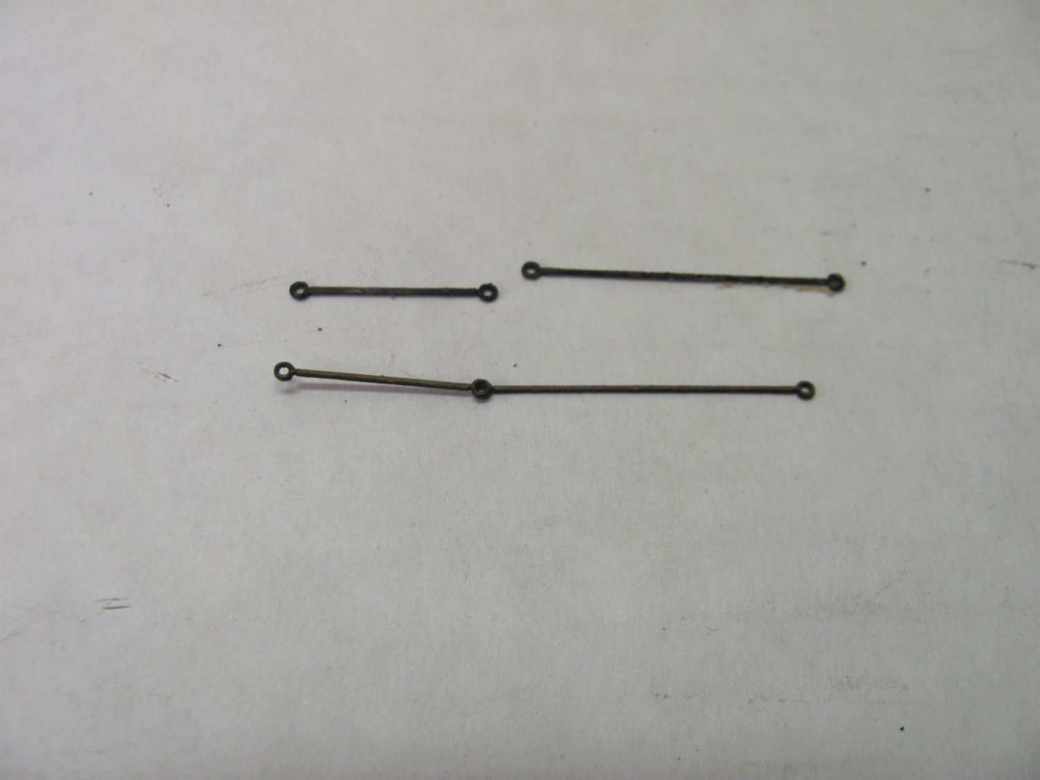
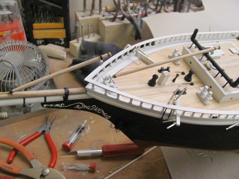
Getting closer to final assembly. These are the two attachment points for the two jib booms.
- 194 replies
-
- 10
-
-
68 turnbuckles later... There are another 24 on the masts, six more for the bowsprit guys, and miscellaneous others.
- 194 replies
-
- 11
-
-
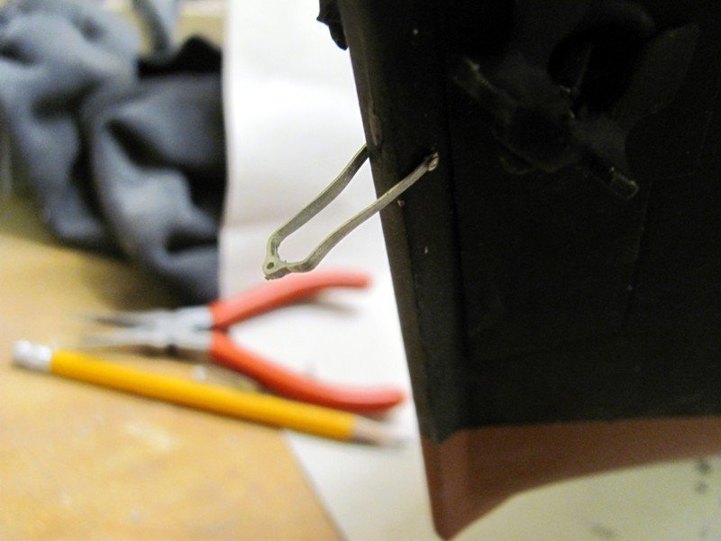
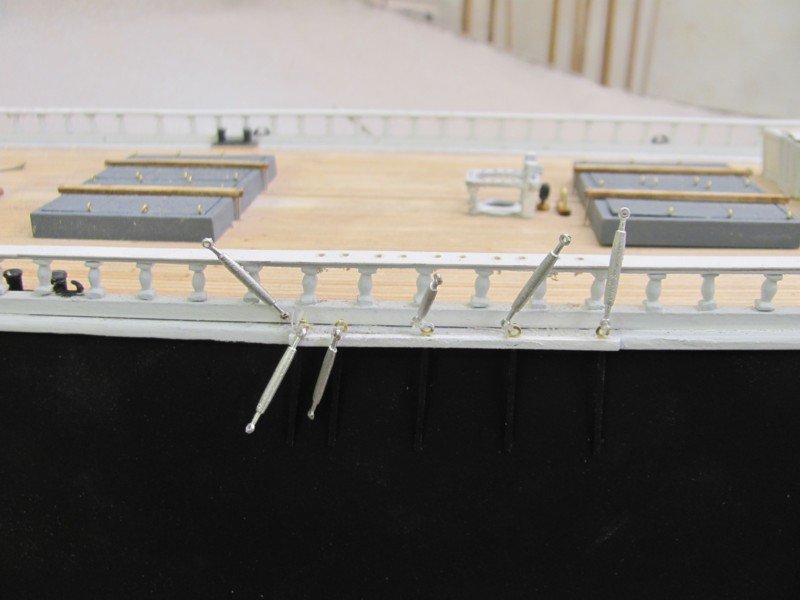
The bobstay irons are going to be a bit fiddly to install. The arms are trimmed to length and a .020" hole drilled at the end of each, then through the stem. A pin is inserted through the three holes, glued to the arms and snipped off. By allowing them to pivot, it makes setting the angle easier when the bobstays are attached. Once they are in place, the irons can be glued in place.
- 194 replies
-
- 10
-
-
Attached the spreaders to the masts today. They're pinned to the cross-trees and actually pivot so the backstay will take a natural angle. The spreaders are laser-cut from .015" laserboard and are laminated (2 ea) which makes them quite rigid.
- 194 replies
-
- 10
-
-
Checking alignment on the masts prior to starting the shrouds. Had to shim one or two to ensure they were all the same height.
- 194 replies
-
- 14
-
-
-
There are 120 holes in the cap rail for belaying pins. I decided not to laser them in because of the potential for breakage. So, you have to drill them but there is a template in the kit that will make this less challenging. You align the first two holes with the space between the stanchions, drill the first hole, stick a belaying pin or piece of rod in the hole to maintain alignment, hold the template in place, and drill away. It actually only takes a few minutes and everything is consistent.

- 194 replies
-
- 12
-

-
-
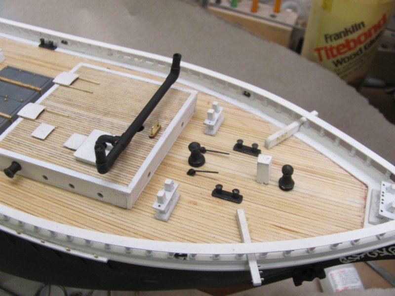
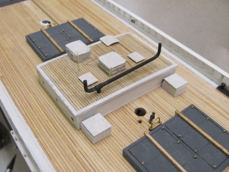
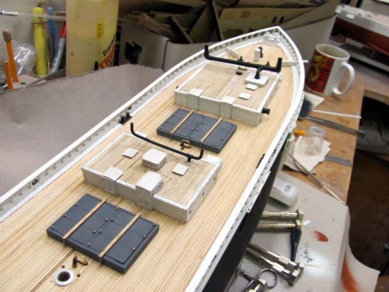
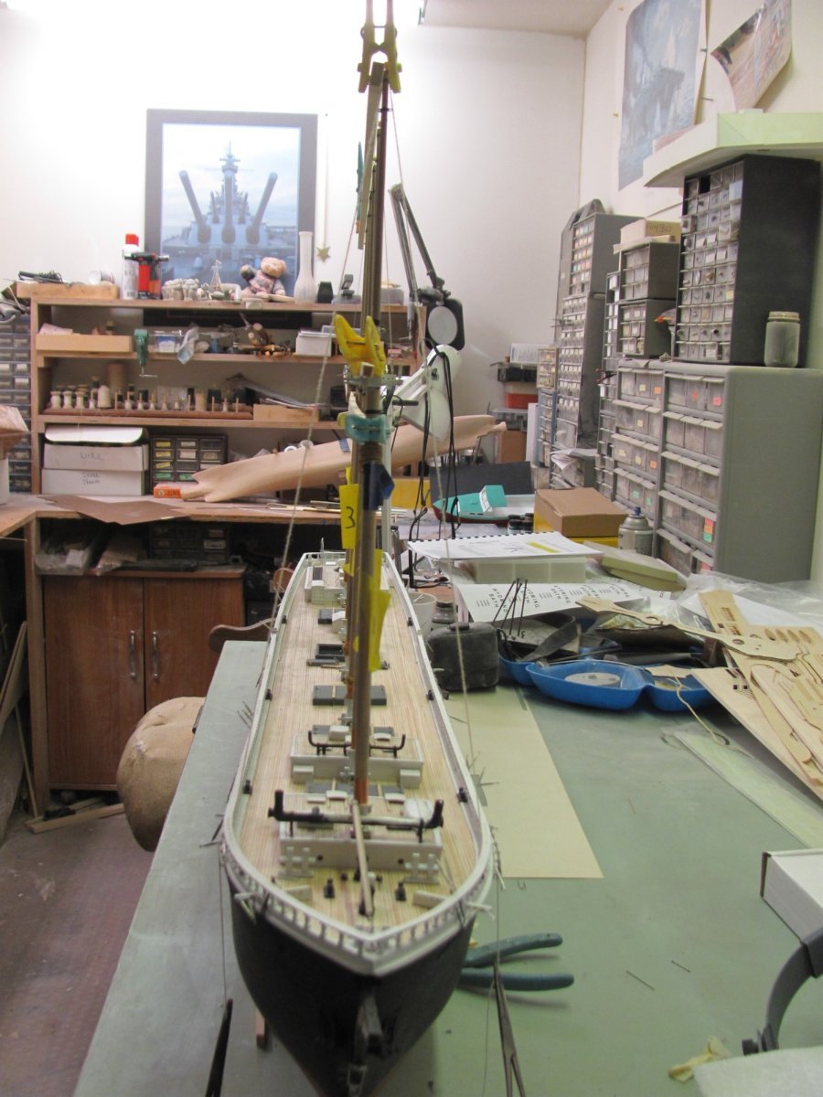
Stacks are now installed on the house roofs. I've also just stepped the #4 mast to serve as an alignment guide for the other five.
- 194 replies
-
- 11
-
-
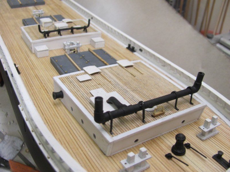
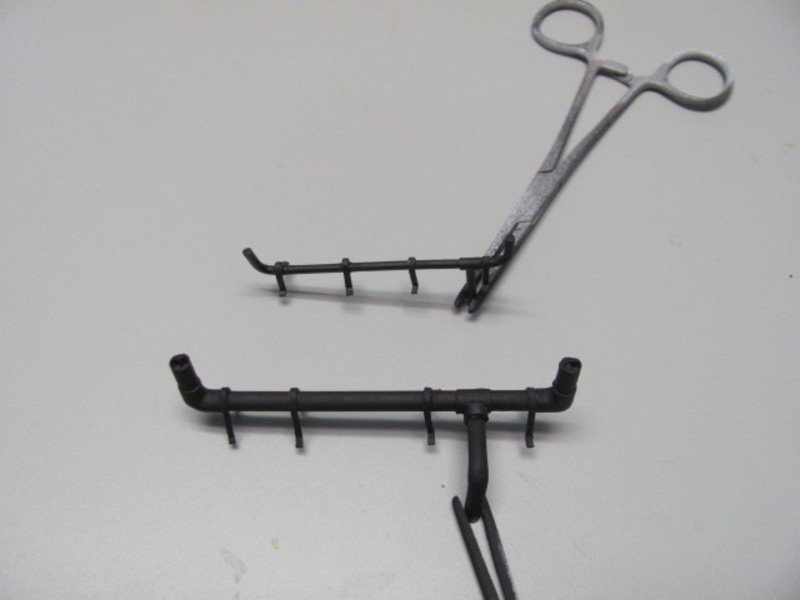
Stack brackets are installed. These are made from 1/64" x 1/16" britannia strips bent over a jig (included with the kit) and trimmed. As an aside, forceps are great for holding items for painting. These are cheap ones that I toss in lacquer thinner after I'm done painting. They clean up easily and can last for years.
-
Some details of the MAINE and OLYMPIA kits I developed for BlueJacket.
(2018_07_2316_35_27UTC)(2020_01_2301_21_01UTC).thumb.JPG.49bd5d513b1511d5ce58ad875a8e3ffc.JPG)
(2018_07_2316_35_27UTC)(2020_01_2301_21_01UTC).thumb.JPG.b7dde29e4fdffbd3944e65d2851586d0.JPG)
(2018_07_2316_35_27UTC)(2020_01_2301_21_01UTC).thumb.JPG.50c64cb8b17b8f08c12f5f83f6098ddf.JPG)
(2018_07_2316_35_27UTC)(2020_01_2301_21_01UTC).thumb.JPG.db00f163b5cb1a7d07bd8cc95ae62ee6.JPG)
(2018_07_2316_35_27UTC)(2020_01_2301_21_01UTC).thumb.JPG.0ccb3ad369acfcdcd87c01cb50aa6b1c.JPG)
(2018_07_2316_35_27UTC)(2020_01_2301_21_01UTC).thumb.JPG.f25b829310196fedd90c3d3c10f6338b.JPG)
-
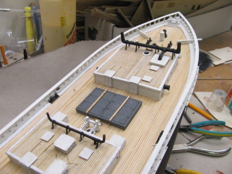
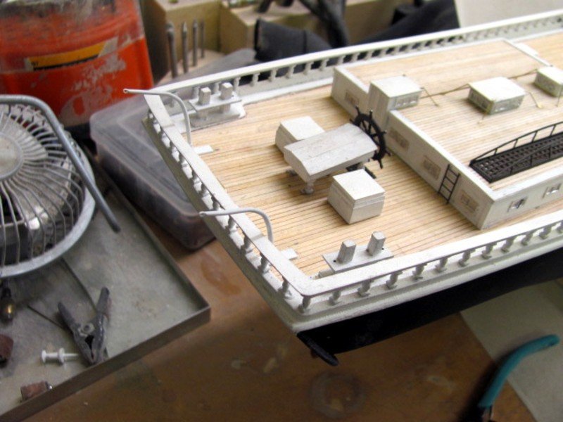
Almost time to start putting in the sticks. Still have to make the brackets for the two stacks, drill holes in the cap rail for belaying pins, and add the rudder.
- 194 replies
-
- 13
-
-
Rather than spend hours looking, I thought I'd start here first. The plans I'm using to develop the kit of WYOMING were drawn by an actual schooner captain who is also a well-known researcher, so I have a warm fuzzy about their accuracy. There is no belaying plan, but that is not much of a problem. I can figure that out based on rigging plans for other schooners. The main problem is that there is no indication of where the halyards on the forecastle mast (that's what P & S called it, as well as #1) tie off. The plans do not show a fife rail nor a spider band on this forward-most mast. Like many schooners, this mast passes through the fore house and the boom jaw rest is quite close to the roof. WYOMING was flush-decked and did not have bulwarks, only a rail with stanchions which doesn't sound strong enough to support pin rails. There are no indications of pin rails anywhere forward. There are two large wooden bitts just forward of the house, each having two belaying pins, but this doesn't seem like enough to be the belaying points for this mast. So, does anyone have an illustraton of this particular configuration that would clear things up for me?

- 1 reply
-
- 4
-
-
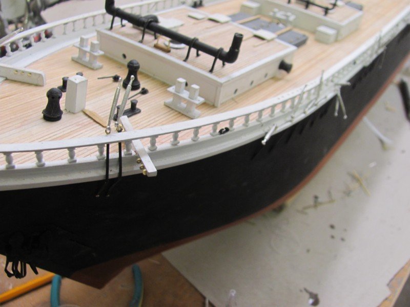
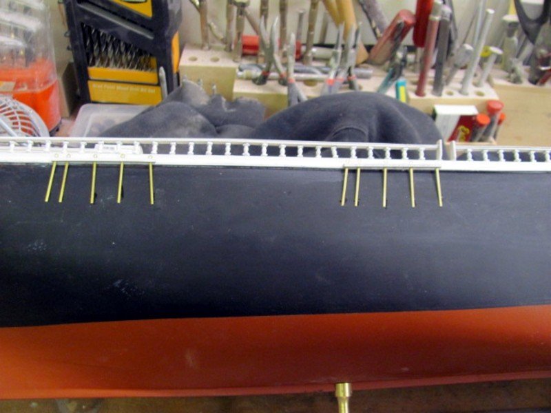
Catheads, horses, and deck pads are on.
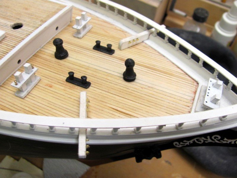
-
All of the starboard chain plates are now in place. They will be black eventually, as the hull will get another coat of black.
- 194 replies
-
- 10
-


(2018_07_2316_35_27UTC)(2020_01_2301_21_01UTC).JPG.8c91c1df2b8986daf6c6e4404113031b.JPG)
(2018_07_2316_35_27UTC)(2020_01_2301_21_01UTC).JPG.c795c82ba2a7de4fadff858d772a58df.JPG)
(2018_07_2316_35_27UTC)(2020_01_2301_21_01UTC).JPG.34e6f553dd1b90600ada2fbe32c63d29.JPG)
(2018_07_2316_35_27UTC)(2020_01_2301_21_01UTC).JPG.9bb1e68597dc63abb2d3e51bb81295ba.JPG)
(2018_07_2316_35_27UTC)(2020_01_2301_21_01UTC).JPG.11be967b56d95a4bf03d360e8e5adef6.JPG)
(2018_07_2316_35_27UTC)(2020_01_2301_21_01UTC).JPG.19f4a026a5ca818196be09a4f9c1a69c.JPG)