HOLIDAY DONATION DRIVE - SUPPORT MSW - DO YOUR PART TO KEEP THIS GREAT FORUM GOING! (Only 51 donations so far out of 49,000 members - C'mon guys!)
×

woodrat
-
Posts
835 -
Joined
-
Last visited
Content Type
Profiles
Forums
Gallery
Events
Everything posted by woodrat
-
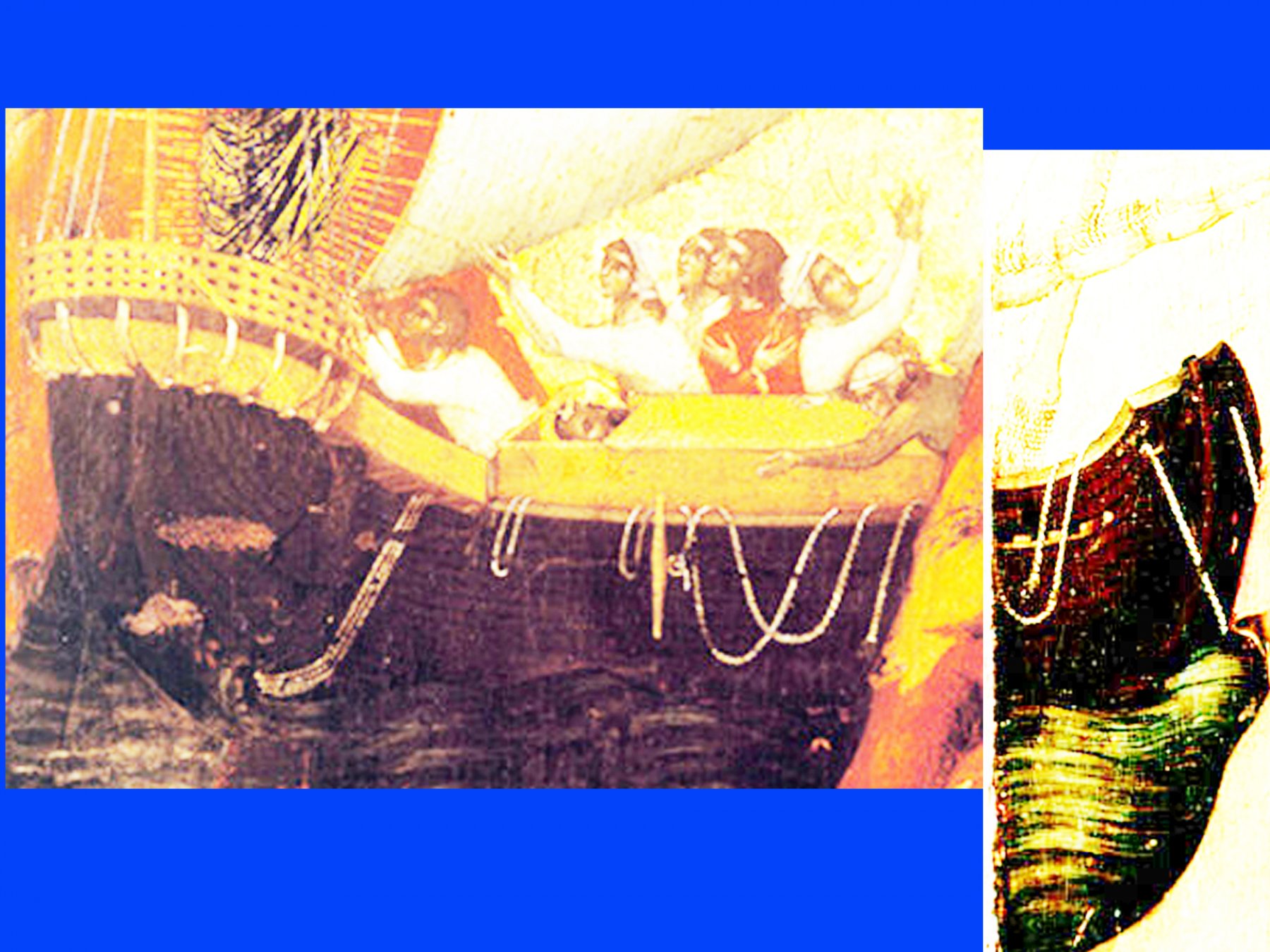
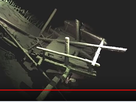
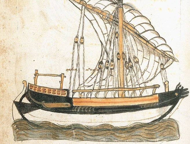
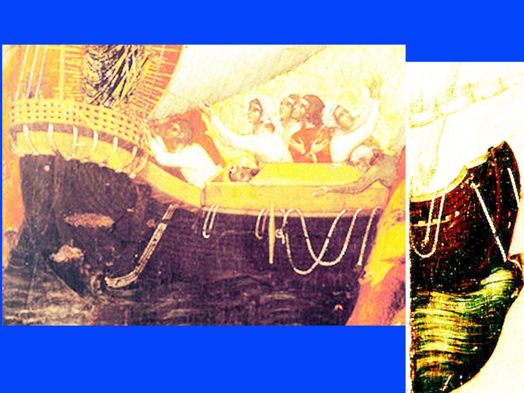
 That is what the curved guides would prevent. There was also a rudder "uphaul" which used to raise the rudder. Additional lashing would be added in a heavy sea. But I am not sure if swing mounts had developed early enough to be seen on a dromon. This is a galley from the Michael of Rhodes manuscript showing a quarter rudder raised and being secured by what I have interpreted as curved guide timbers This is one of the black sea wrecks of a similar vessel showing the quarter rudders and the throughbeams. I think I can see evidence of a swing mount....maybe?
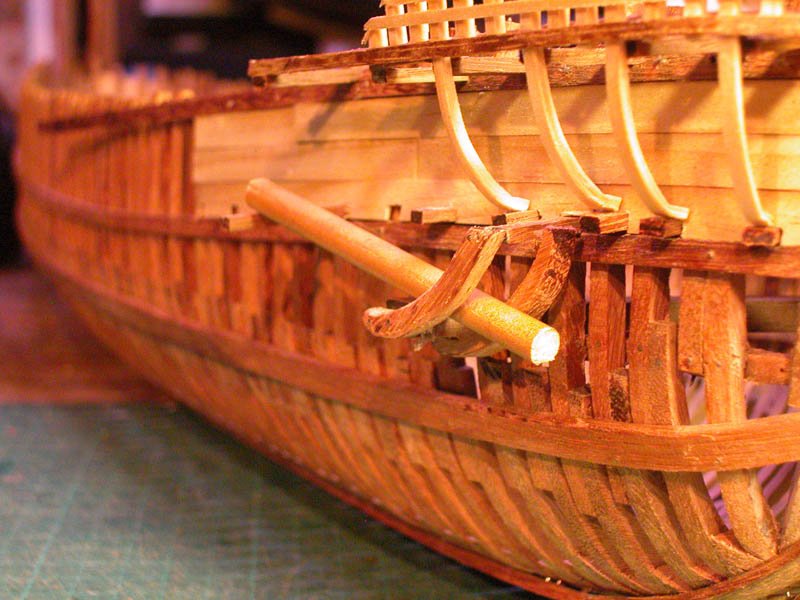
- 263 replies
-
- 8
-

-
- nave tonda
- round ship
- (and 2 more)
-
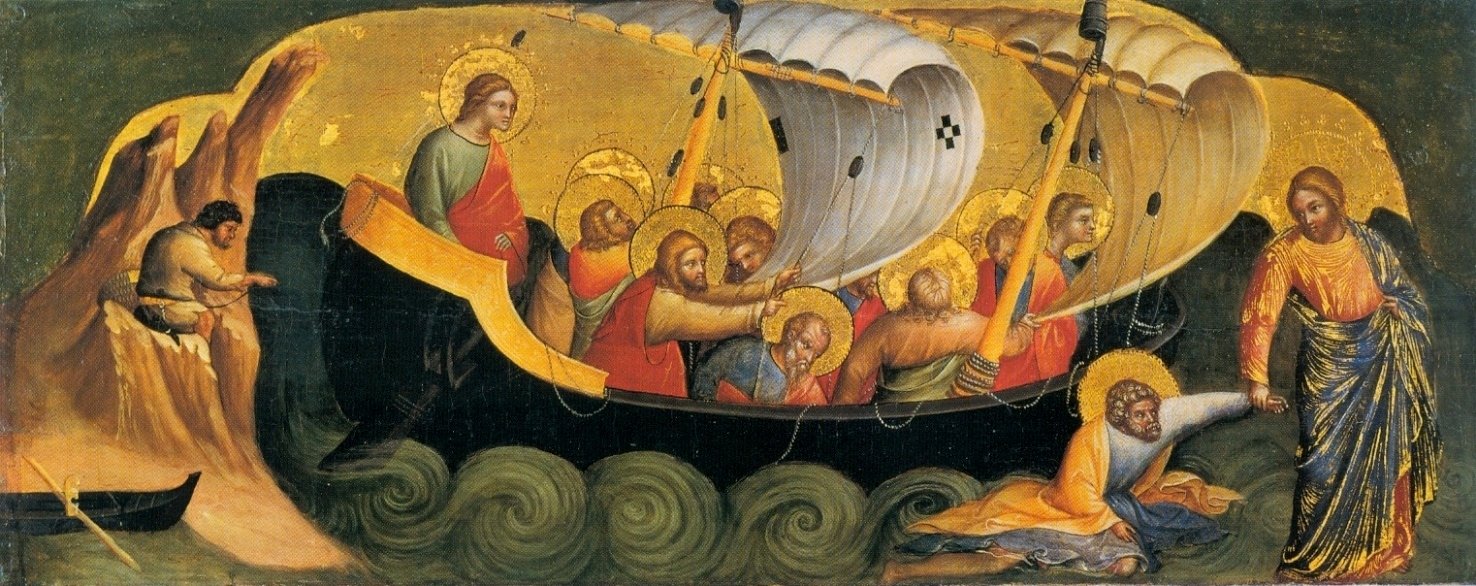
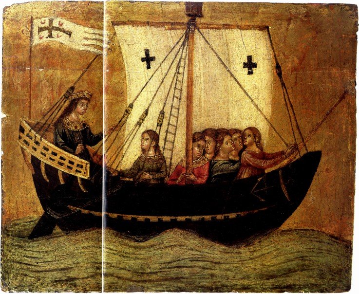
The rudders, strictly speaking, won't be "lashed" to the throughbeams, rather held by 3 point pressure generated by the rudder "downhaul" which pulls the rudder onto the aft edge of the lower throughbeam and the forward edge of the upper beam. If that is as clear as mud in a beerbottle, the model will make it clear. This is seen in a number of illustrations by Veneziano:
- 263 replies
-
- 3
-
-
- nave tonda
- round ship
- (and 2 more)
-
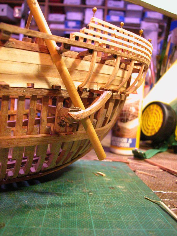
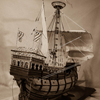
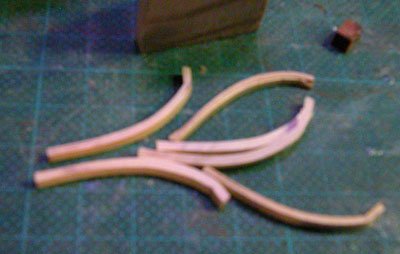
This in my concept of the swing mount used to attach the quarter rudders. The rudders had to be removed and given to the port authorities as a safeguard against sneaking out without paying port fees. So the rudders ahd to be easy to remount. Also, loss of a rudder was not uncommon at sea and mounting a new rudder had to be straightforward. (and a sight easier than remounting a stern post rudder. The quarter rudder had to be able to swing horizontally out of the way in shallow water to prevent damage. Also the weather rudder could be withdrawn if the ship was heeling. The ship was steered then by the lee rudder. There were many different variants of swing mounts. Here is a contemporary illustration showing a swing mount. This how it is on my ship: This the rudder rotated up ( this would be done by a rudder hoist) and would be even more horizontal when fully raised. Dick


- 263 replies
-
- 13
-
-
- nave tonda
- round ship
- (and 2 more)
-
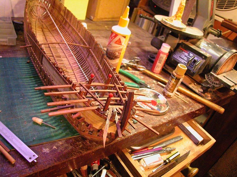
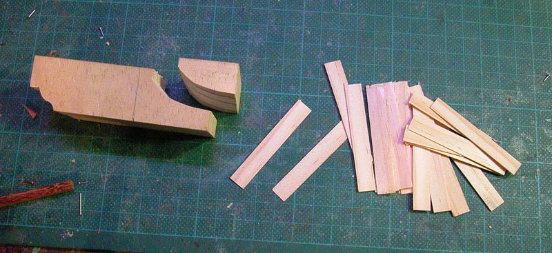
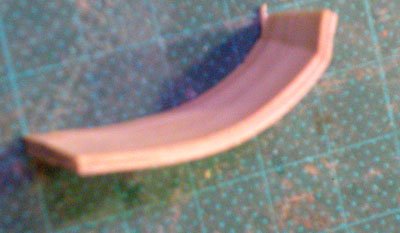
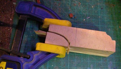
This is my plank bending jig. Planks are soaked for 24 - 48 hours. No steaming. the framing of poop. The stern deck framing is underneath the poop. Note the pillars with the red balls. This will become the shelter for the steersman. Making the external supports for the poop. This can be used to make complex curves. 0.5 mm planks are glued and clamped and allowed to set overnight. It saves a lot of carving. sorry about the soft focus I will show the swing mount for the quarter rudder in the next installment Cheers Dick

- 263 replies
-
- 8
-
-
- nave tonda
- round ship
- (and 2 more)
-
Thanks Steven and Druxey and everyone for the likes Yes Steven I have read Lawrence Mott's definitive treatise on the Development of the Rudder. I use this plus some of my own interpretation of the iconography. In addition, new information from the Black Sea wrecks will be used to reconstruct a usable swing system for the quarter rudder. Cheers Dick
- 263 replies
-
- 4
-
-
- nave tonda
- round ship
- (and 2 more)
-
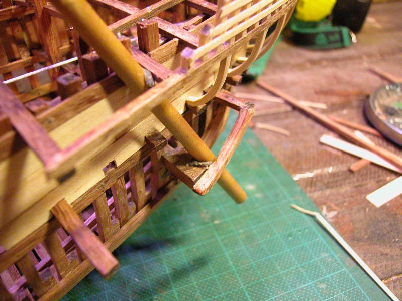
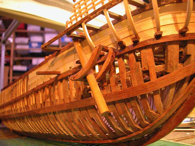
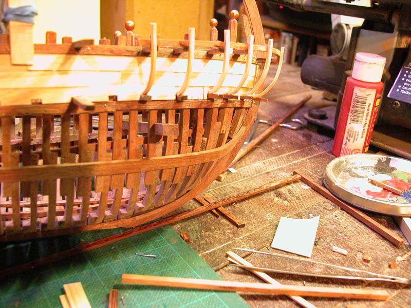
The wales have been attached. I have inserted the main throughbeam in the stern. This a major structural element as the quarter rudder applies its turning moment through this beam. Pilgrims in round ships have described how, travelling in steerage, they could feel every movement of and twist of the ship when they leant against the throughbeam. Cheers Dick


- 263 replies
-
- 13
-
-
- nave tonda
- round ship
- (and 2 more)
-
Thanks Carl and Steven. The hull framing is complete and awaiting fairing so I can fix the wales. Overall the framing of the bow and stern is fairly consistent with the Contarina find. I am presently researching the quarter rudders and have decided to make a swing mount. This allowed the rudder to be swung up and secured when not in use and allowed easy removal and replacement of the rudders ( in some mediaeval ports it was a requirement on anchoring or docking to remove the rudders so the master couldn't do a quick scarper and avoid paying the port fees). Cheers Dick

- 263 replies
-
- 15
-
-
- nave tonda
- round ship
- (and 2 more)
-
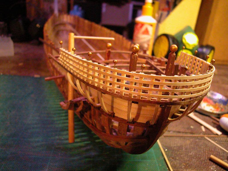
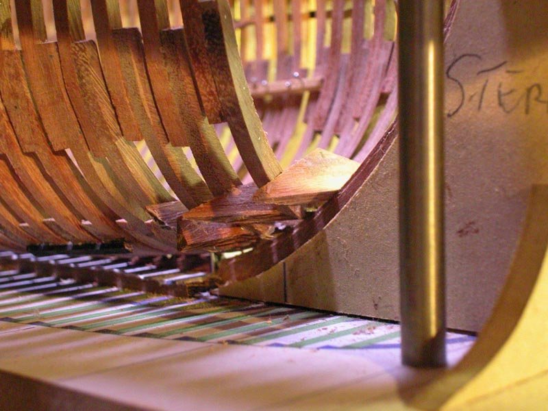
Chaps, I have completed the framing of the stern and used a slightly different technique. It was quite difficult. Fairing of the frames and pinning was made easier by keeping the stern separate from the main hull. I will now attach the stern module. Making the tilt floors 15 deg. angle then angle to match that of the futtock Tilt floors fixed in place Stern uprights in place stern detached and fairing up commences Fairing done and breasthooks in place cheers Dick


- 263 replies
-
- 15
-
-
- nave tonda
- round ship
- (and 2 more)
-
One of the difficulties will be matching the newly restored sections of the deck and hull to the original surviving portions of the wreck. You may wish to consult some of the MSW members who have expertise in "aging" wood. Or, alternatively, as archaeologists do, leave the restored portion obviously different to showcase the restoration. Good work so far Dick
- 740 replies
-
- 5
-
-
- Tudor
- restoration
- (and 4 more)
-
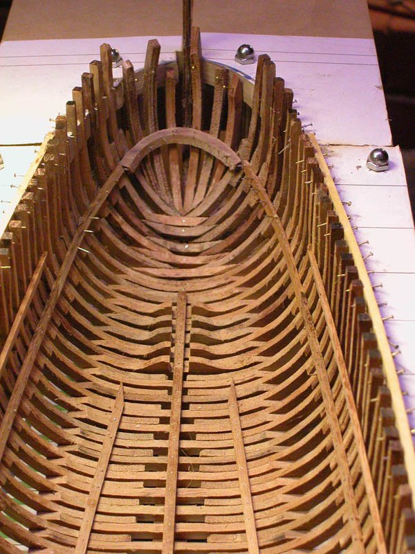
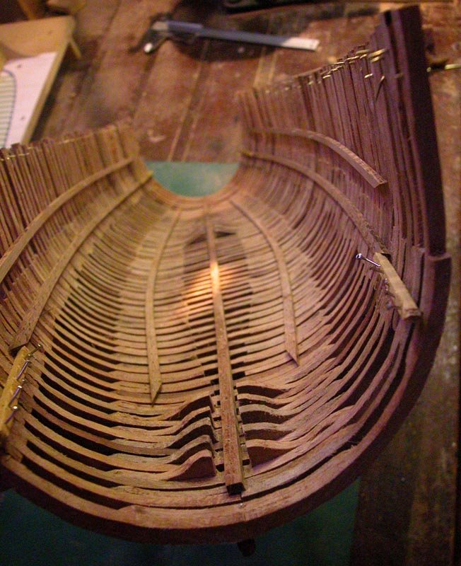
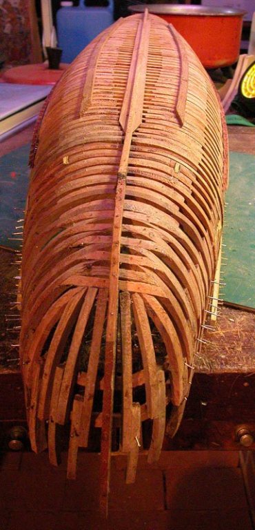
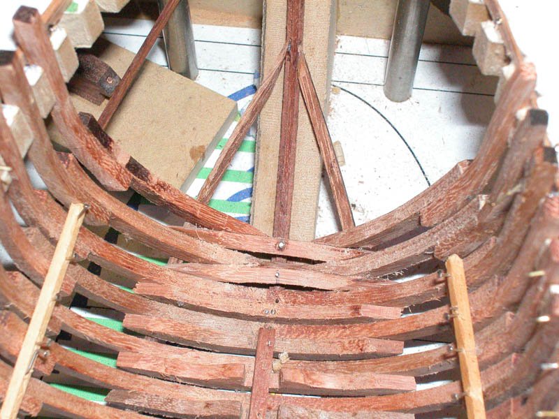
I was able to complete the framing of the bow section. The tilted floors from the wreck were reproduced. The timbers above this level in the Contarina 1 wreck did not survive and have been guessed at. You will note that canted frames became necessary and seem to work. Breasthooks and deck clamps applied. Dick


- 263 replies
-
- 13
-
-
- nave tonda
- round ship
- (and 2 more)
-
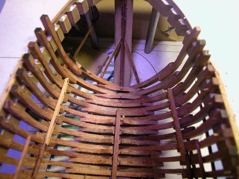
So do I. The venetians managed it. Unfortunately not all of the bow survived so some extrapolation will be needed. Dick
a.jpg.24342ec5f364f8983da11d9661ca3b52.jpg)
- 263 replies
-
- 5
-
-
- nave tonda
- round ship
- (and 2 more)
-
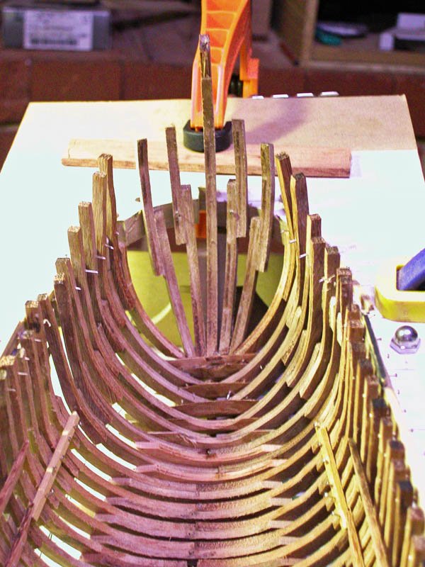
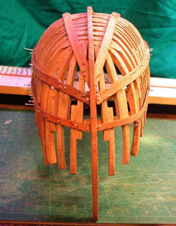
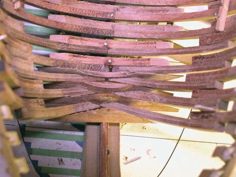
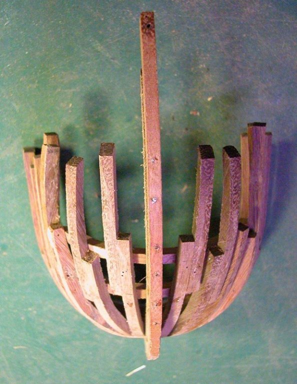
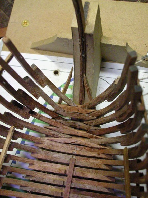
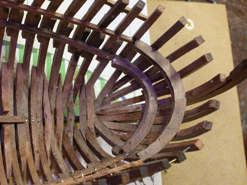
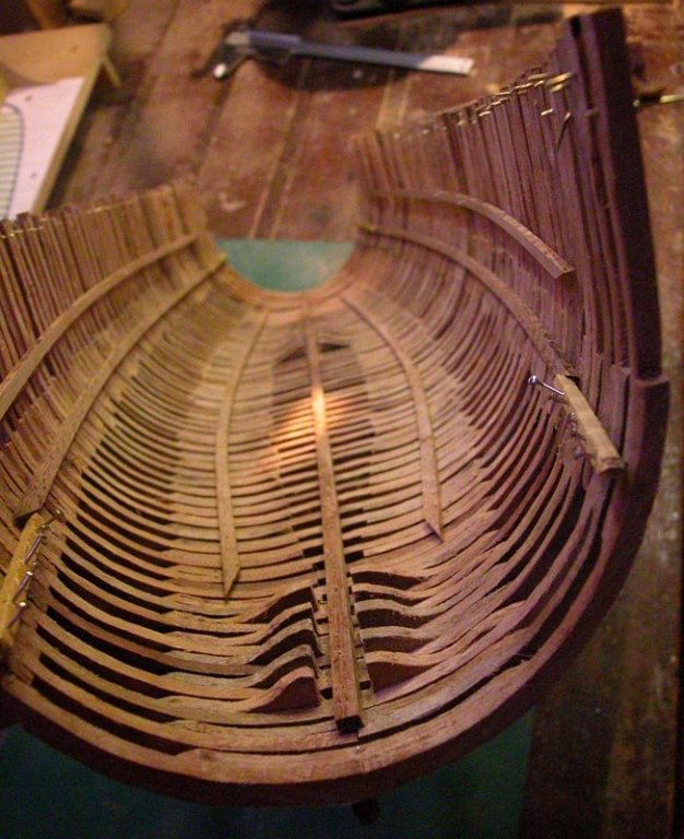
The first two bow frames are in. Not quite perfect but I think I have the hang of it. Although there are no actual cant frames as we usually understand them, it seems inevitable that some frame rotation or canting creeps in. Note how the floor timbers are now tilted to match the curve of stempost. the curve of floors and futtocks is the same as for the rest of the ship. Cheers Dick

- 263 replies
-
- 13
-
-
- nave tonda
- round ship
- (and 2 more)
-
Steven, just ease of access for the Dremel. You could join the posts up now. The strength is largely in the wales rather than the attachment of the keel to the posts. I need the frames in place before I can extend the wales to the posts. There were no cant frames in this vessel and the bow and stern frames were curved floors placed along the curve of the posts and reinforced with vertical futtocks. I believe there must have been some vertical bow timbers to reinforce the hawse holes but these were not preserved in Contarina 1 Thanks, Patrick for the info on iron nails. What was the book? Steffy? Cheers Dick
- 263 replies
-
- 1
-
-
- nave tonda
- round ship
- (and 2 more)
-
Only nails are being used as this was how the original was built. No trenails were used according to the relazione of the excavation. I have not connected the stem and stern posts. I will do this after the bow and stern framing is completed and faired. I used this method for my Essex and Gros Ventre builds. Dick
- 263 replies
-
- 3
-
-
- nave tonda
- round ship
- (and 2 more)
-
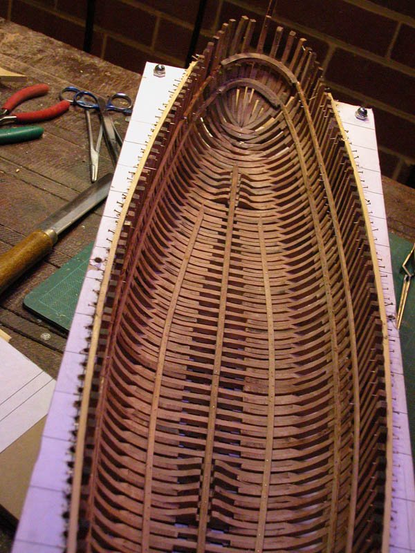
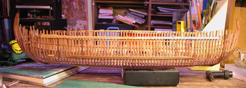
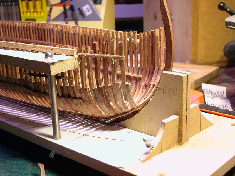
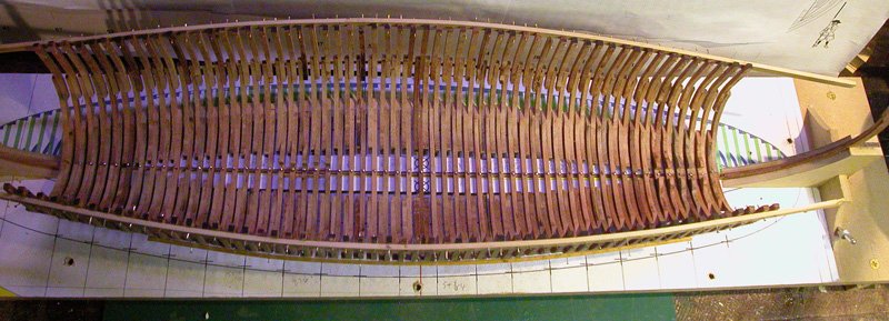
Thanks, Steven. I have faired the hull and installed internal stringers and clamps.The larger wales are positioned where the floors overlap the futtocks at the bend of the bilge as well as where the futtock overlaps the top timber at max breadth. I haven't finished pinning the wales. No trenails were used on the Contarini 1, only nails. I have put the hull back into the building frame so I can apply the ribbands for bow and stern. Cheers Dick

- 263 replies
-
- 14
-
-
- nave tonda
- round ship
- (and 2 more)
-
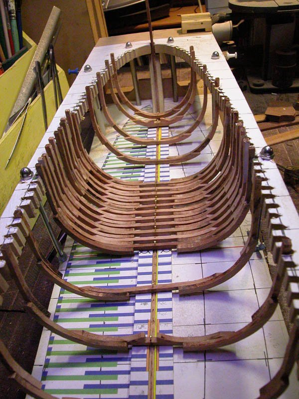
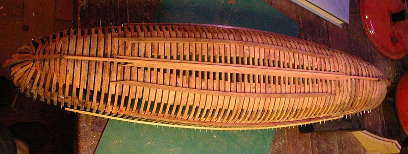
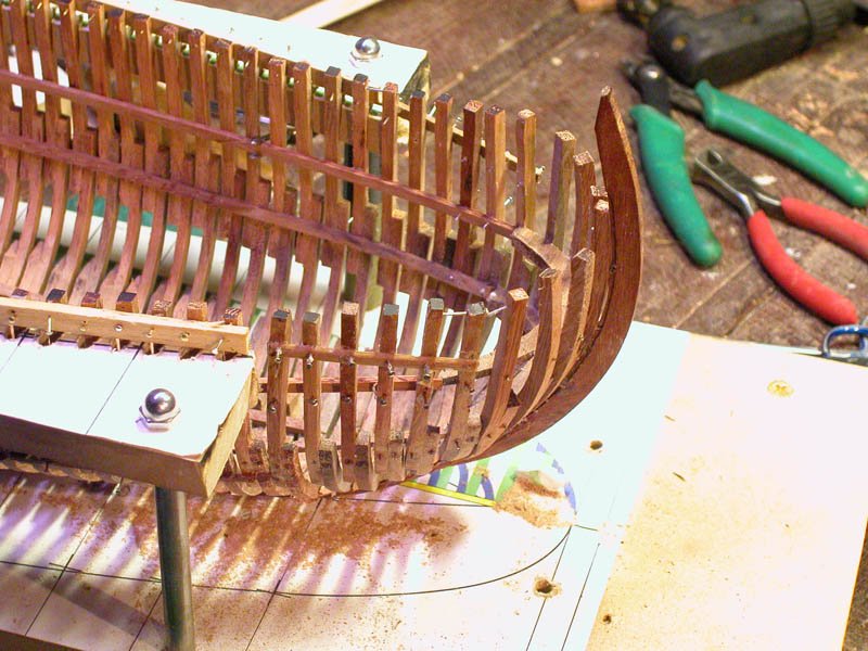
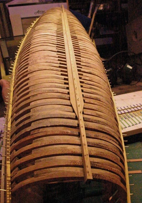
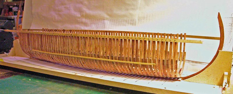
The hull is removed from the building board while it is faired. Applying the garboard strake and ribbands is straightforward. Then it wil go back on the board. Dick
- 263 replies
-
- 18
-
-
- nave tonda
- round ship
- (and 2 more)
-
Carl, I have removed the support for the moment so I can properly fair up the floors under the vessel. I may put it back on later but the temporary wale around the top timbers seems to provide good stiffness. The stem and sternposts are not yet fixed to the keel. This allows access to the inside of the hull for fairing. I am learning as I go but, so far, so good. Dick
- 263 replies
-
- 3
-
-
- nave tonda
- round ship
- (and 2 more)
-
Michael, I haven't mentioned it because I'm not sure. I believe it is karri or marri , west australian hardwood. My son had used this wood in one of his architectural models and there were a lot of left overs. It seemed to cut, machine and sand well and was close grained. Therefore, being a cheapskate and not wanting to waste good wood, I have used it. Thanks for all the likes, guys. Cheers Dick
- 263 replies
-
- 4
-
-
- nave tonda
- round ship
- (and 2 more)
-
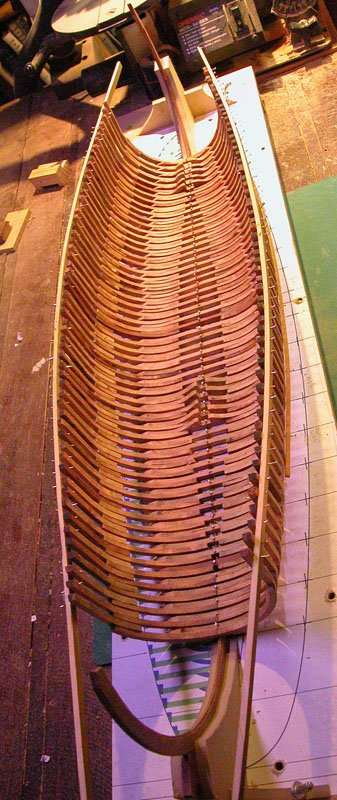
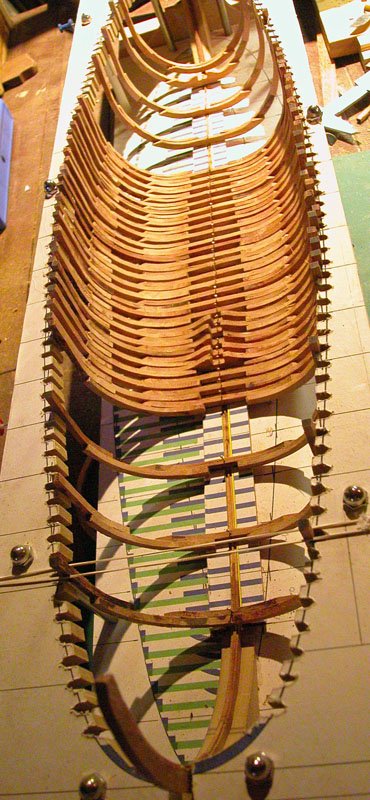
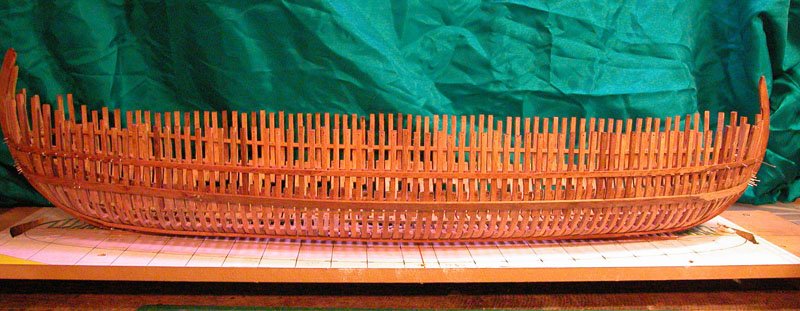
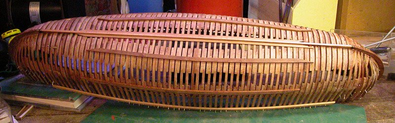
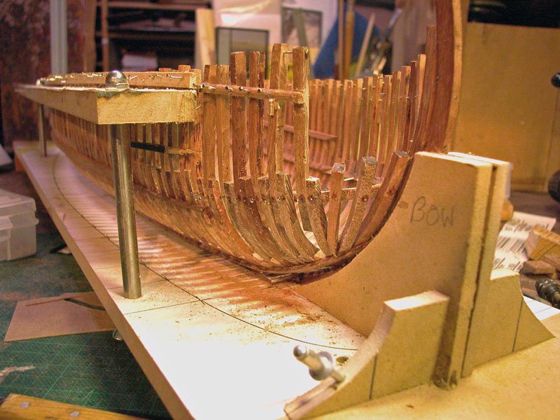
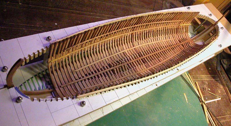
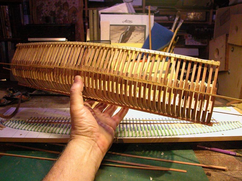
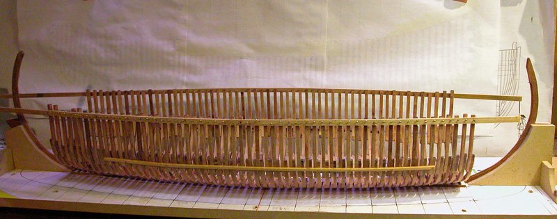
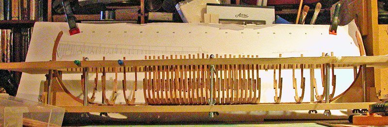
frames fixed to keel and some ribbands applied. Building stand frame support removed. Now to finish the ribbands fore and aft and make the bow and stern framing. Dick
- 263 replies
-
- 14
-
-
- nave tonda
- round ship
- (and 2 more)
-
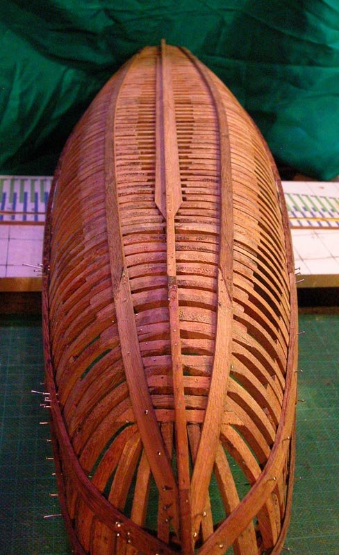
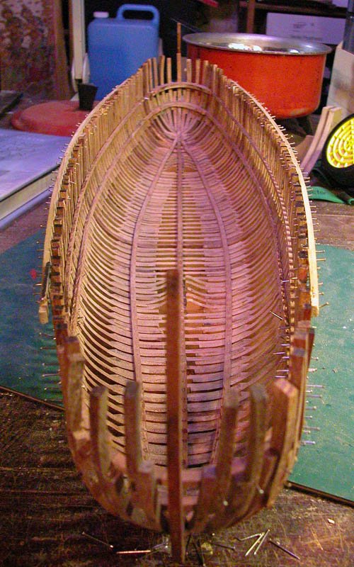
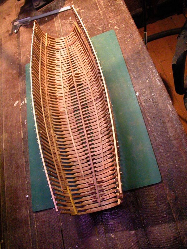
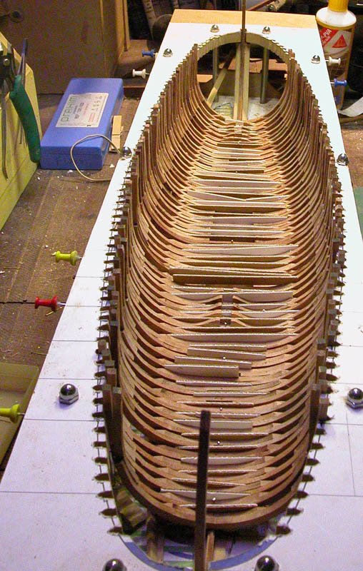
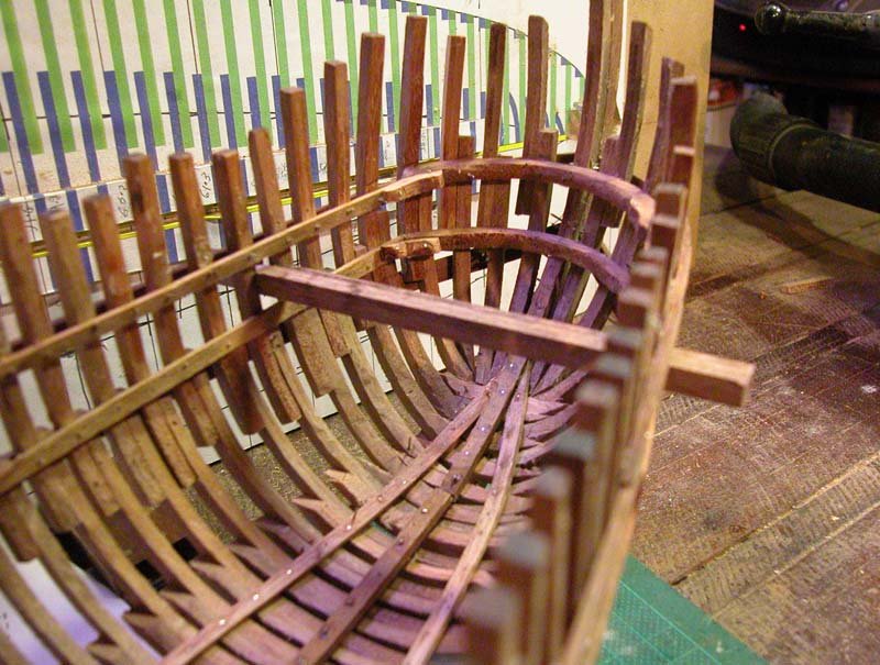
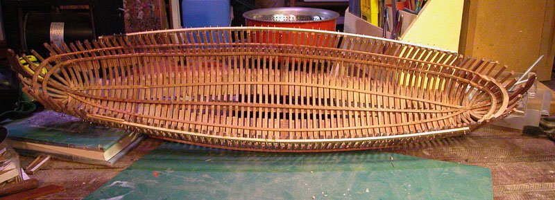
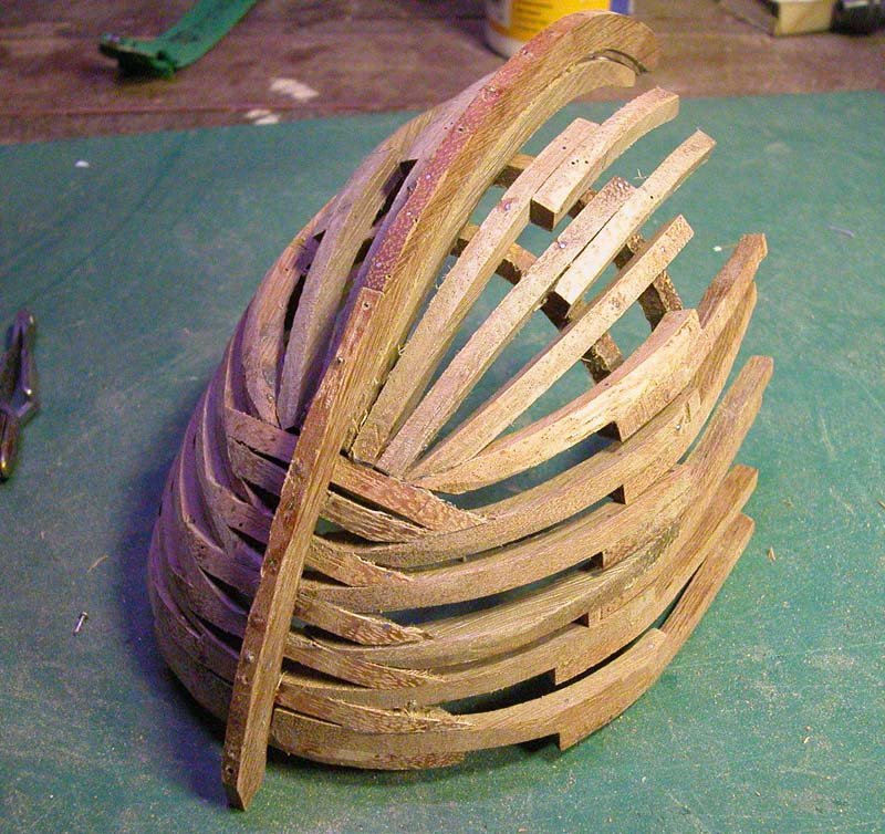
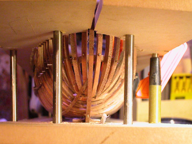
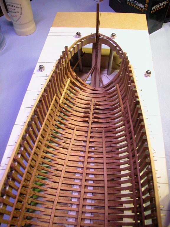
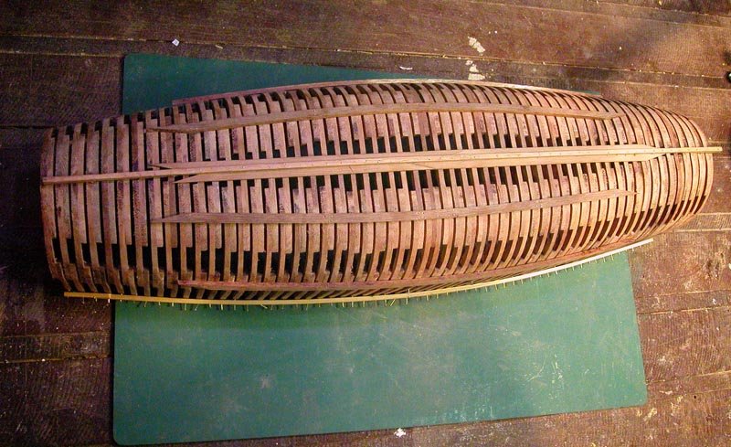
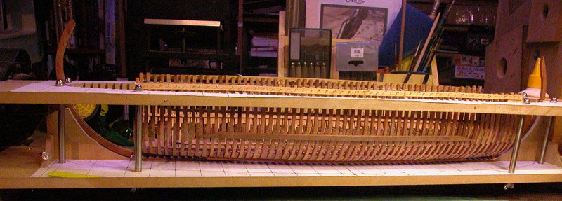
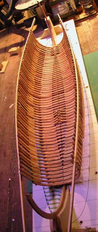
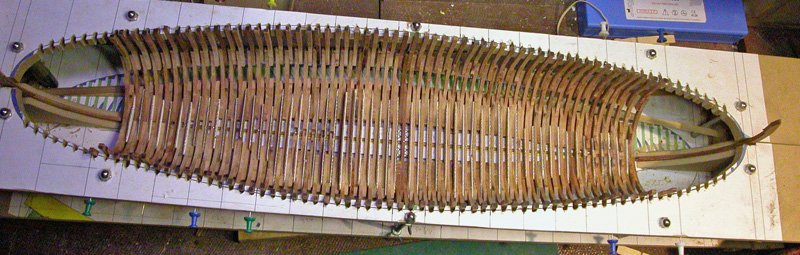
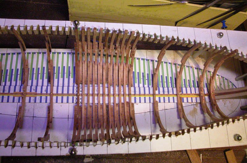
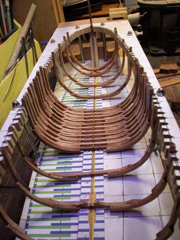
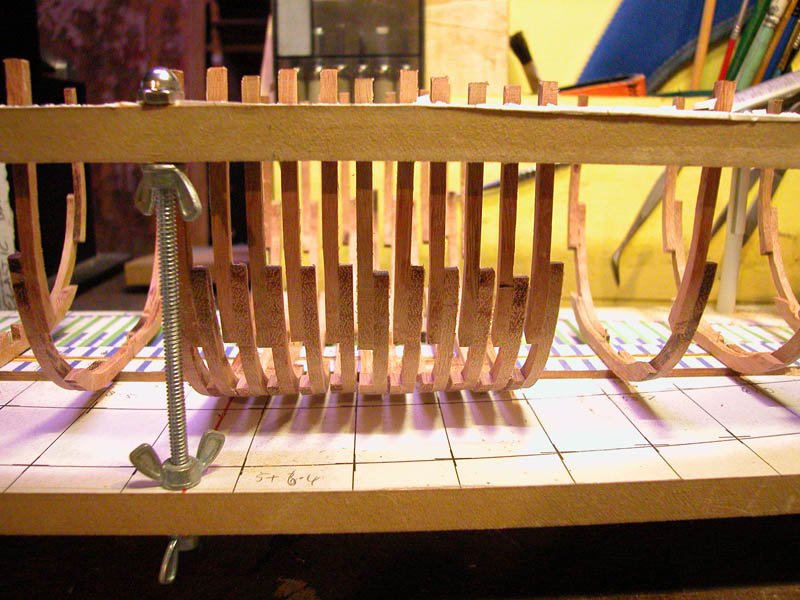
Thanks chaps. I have now completed and faired all frames between the master frame and the tail frames. They have now to be fixed to the keel . Note the card strips maintaining the space between frames. After this ribbands will be attached to the hull to properly align the frames. Only then can the bow and stern framing be made based on the ribbands. Dick

- 263 replies
-
- 12
-
-
- nave tonda
- round ship
- (and 2 more)
-
Sorry for the lack of progress. I have been away from the shed several weeks. I have completed some mor framing including the step for the mainmast. Had to remake some frames which were inaccurate. Cheers Dick


- 263 replies
-
- 16
-
-
- nave tonda
- round ship
- (and 2 more)
-
Is this a sentimental journey? Why not just start again, it might be easier Dick
- 740 replies
-
- 1
-
-
- Tudor
- restoration
- (and 4 more)
-
Looking good. I like the through beam to support the rudder. A similar through beam was found in situ in the Contarina 1 wreck. I assume a tackle going forward to pull the rudder against the beam and a tackle going aft to raise the rudder. What is seen on some illustrations is a kind of rail to hold the rudder post in against the hull as it is being raised. Dick
-
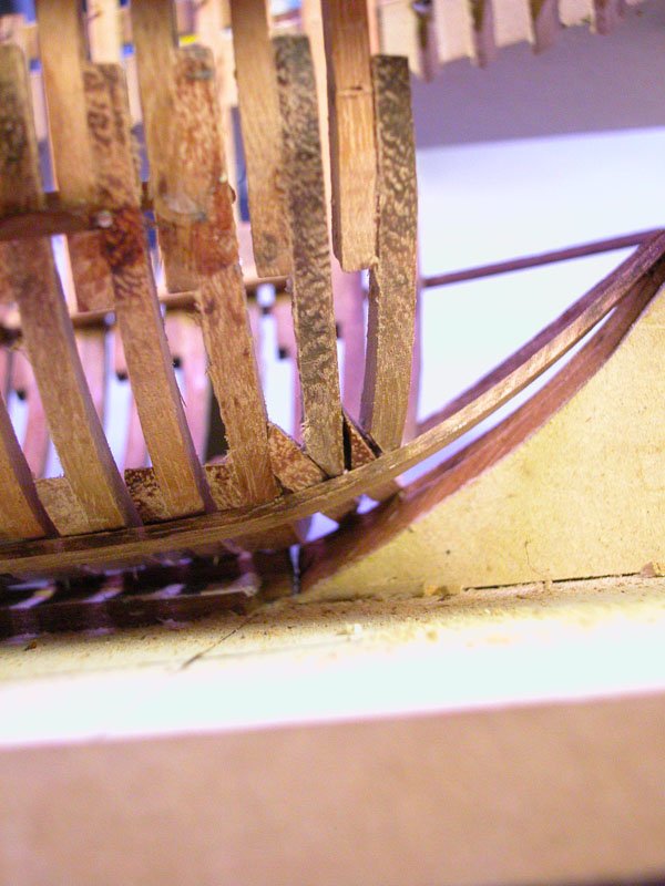
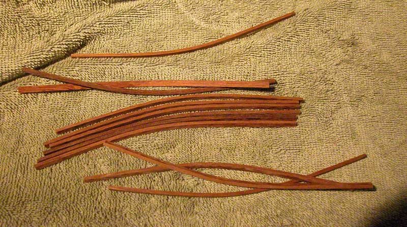
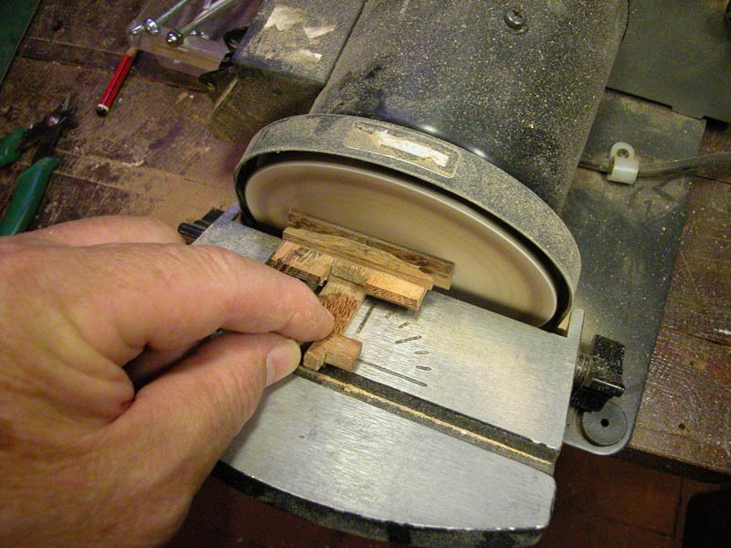
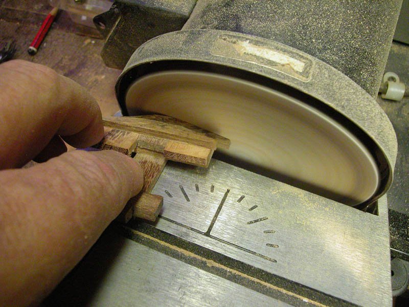
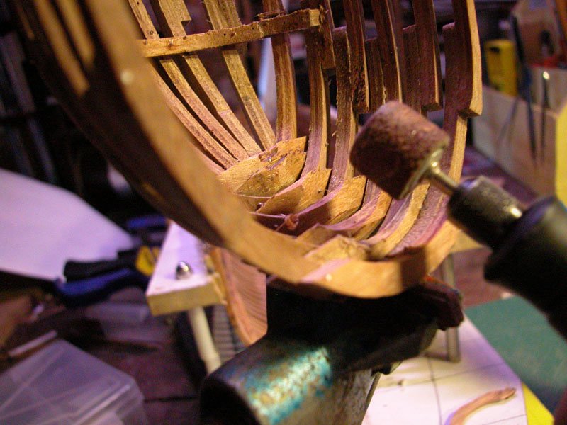
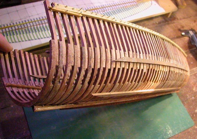
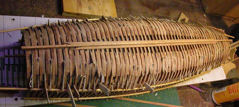
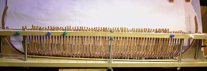
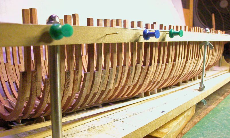
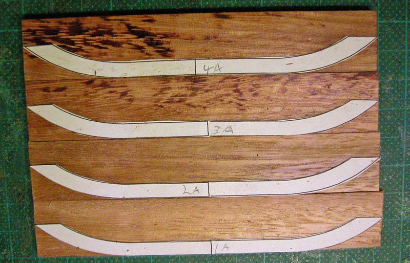
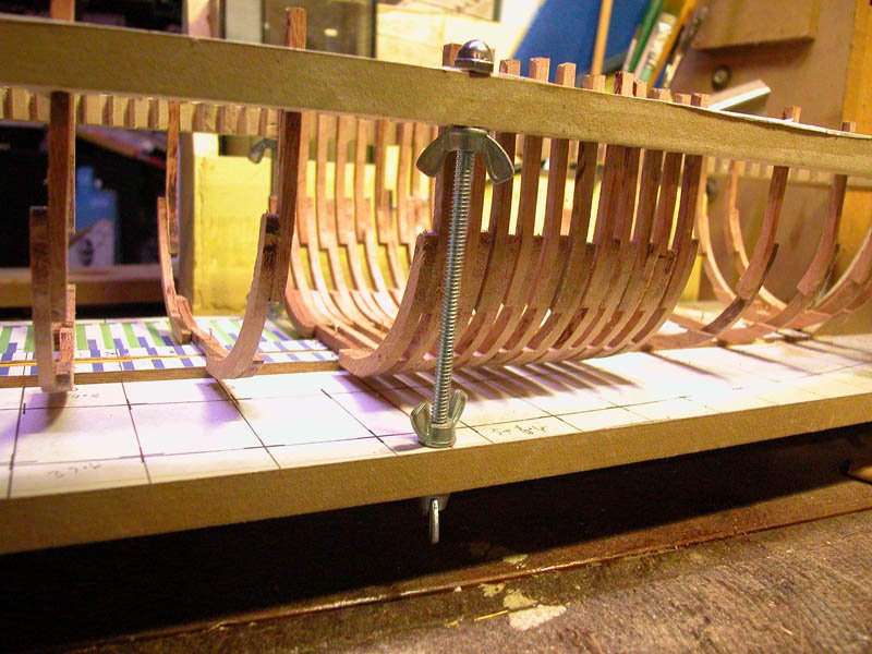
Thanks Ondras and Steven. Just had time to dash off some frames. The jig certainly speeds up the process. just thinking about mediaeval building. The foothooks and top timbers could be premade elsewhere. Only the floors need be individually shaped onsite and even this would have been somewhat automated. This helps explain how the shipwrights of the Arsenale could lay down an entire galley in three or four weeks. This shows the gradual narrowing of adjacent floors. Dick
- 263 replies
-
- 14
-
-
- nave tonda
- round ship
- (and 2 more)
-
I have had another look at the Catalonian pic. With magnification I think I can see a hook at the end of the "chain". In the Aeneid Vatican pic, I am convinced (pun) that a chain is shown. Dick