woodrat
-
Posts
835 -
Joined
-
Last visited
Content Type
Profiles
Forums
Gallery
Events
Everything posted by woodrat
-
 Thanks, Tom, Druxey, Carl and Vivian. I greatly appreciate the positive comments and all the likes. It keeps the oxytocin levels high. I still have a few things to do such the anchors and some titivating before I seal it away in the case. I am thinking of the next project which may be a 13th or 14th century mediterranean lateener (not a crusader ship, Steven). As well, I must finish the framing of the Gros Ventre which was put on hold because of the carrack build. Cheers Dick
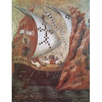
-
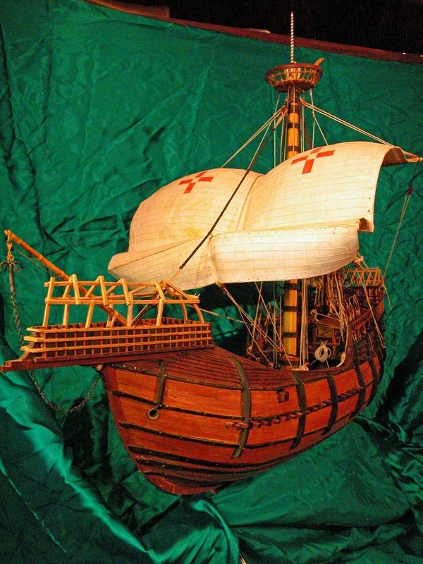
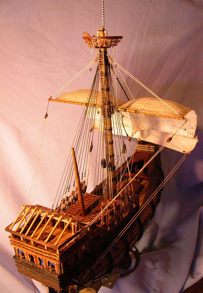
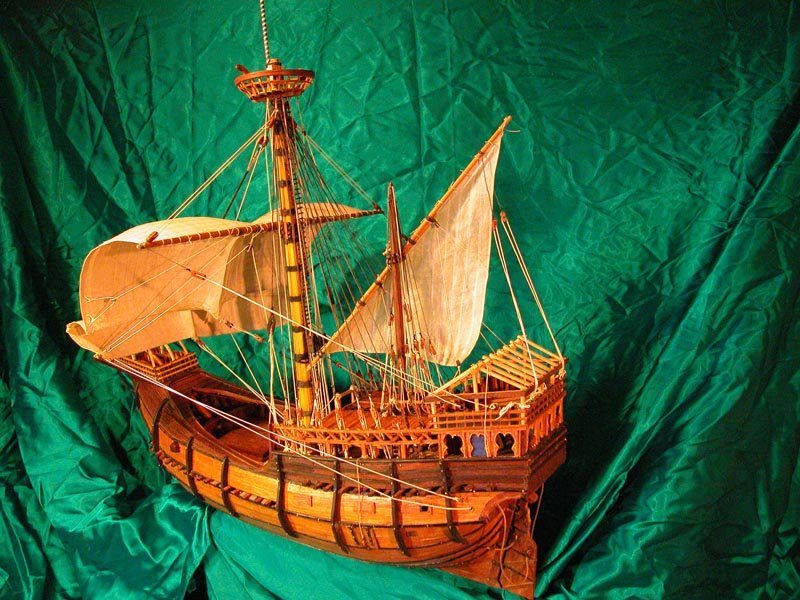
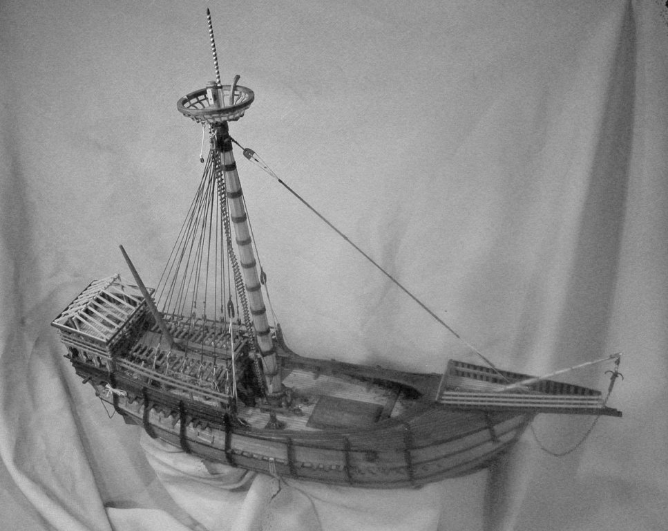
Substantially finished now. Just decorative work, flags and figurehead. Display case underway. Cheers Dick
- 632 replies
-
- 18
-

-
I have sent an email to Seawatch Books and one of the directors of Texas A&M. Lets see what they say. Dick
-
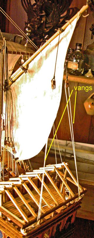
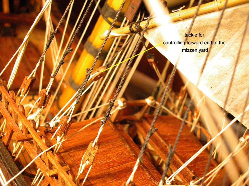
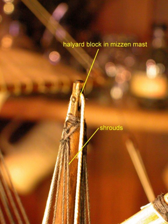
Thanks Jesse and Druxey, this would be possible but I dont have any experience in publishing except in peer review journals. Maybe I would have to self-publish. Would there be a market? All suggestions welcome. Mark, yes that is my impression too. Having loosened the parrels, the vertical position of the yard is changed with the halyard, the tacks and vang are used to angle the yard and the sheet (which is not yet installed on the photos) adjusts the fullness of the sail. Also, the shrouds are slackened on the lee side. I would recommend that Landstrom (The Ship) be consulted for his excellent description of the technique used for tacking a lateen sail of the period. I think so. Some lateeners of this and earlier periods show the top of the mast angled forward to presumably aid the parrels by the halyard pulling them against the mast so they roll better?? Also, with the parrel tackle loosened, having the halyard pulling forward world further loosen up the yard to allow it to move up or down or rotate on the mast. However, most fifteenth century lateen mizzens show the top of the mast as straight. Confusing, isn't it! Dick
-
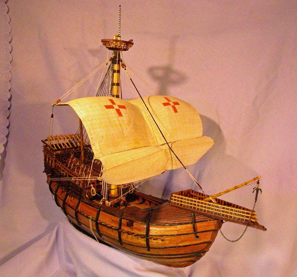
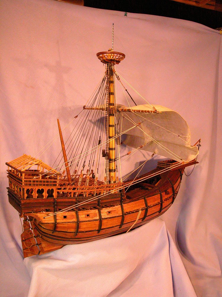
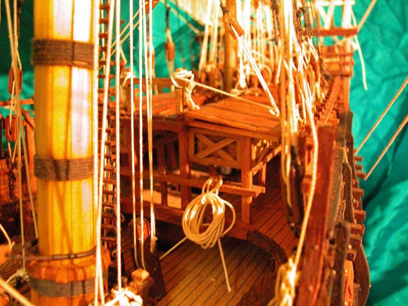
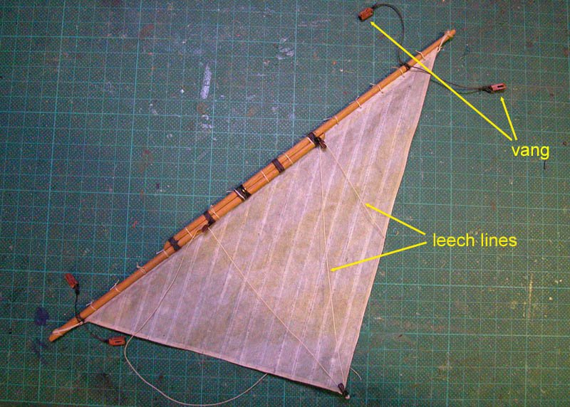
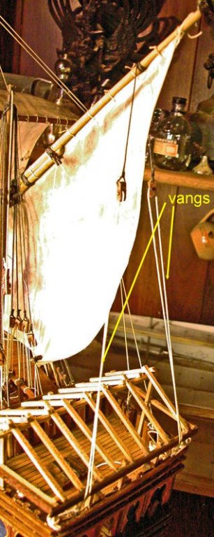
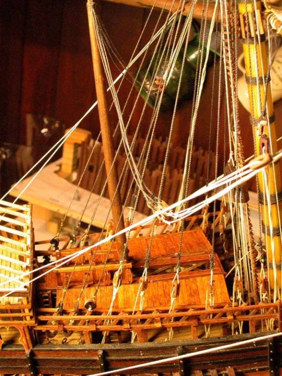
There is light at the end of the tunnel. Earlier in this build log I was pessimistic about unravelling mediaeval rigging. I believe i have come a long way toward now somewhat understanding their rigging and the constraints forced upon the sailor of the middle ages. The rigging of the middle ages should not be compared to that of the later centuries as evolution was proceeding in leaps and bounds. Much of what the mediaeval sailor used looks strange and complicated to us. It was however, in essence practical. The rigging of the mizzen mast is a case in point. In contrast to later rigs, the mizzen of the fifteenth century was based on the lateen rigs of previous centuries. The sail, for instance, was deployed outboard of the shrouds. The following is my attempt at depicting this rig. the mizzenast installed. Note it is a single pole mast, not "built" as was the mainmast the mizzen yard and sail. Note that a single line is used for furling clew and leech I have decided that it is not appropriate to have a foremast as it would look naff. The Mataro nao was a two master and was of the same period. More soon Dick

- 632 replies
-
- 12
-
-
Thanks, Steven. You are right about gunwales. The Beauchamp drawings are about the same date and show the artillery propped on the wale. Dick
-
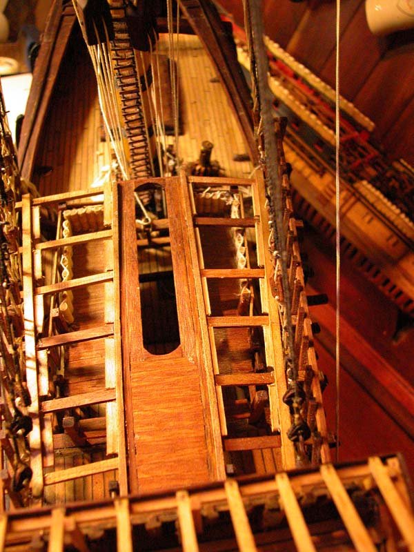
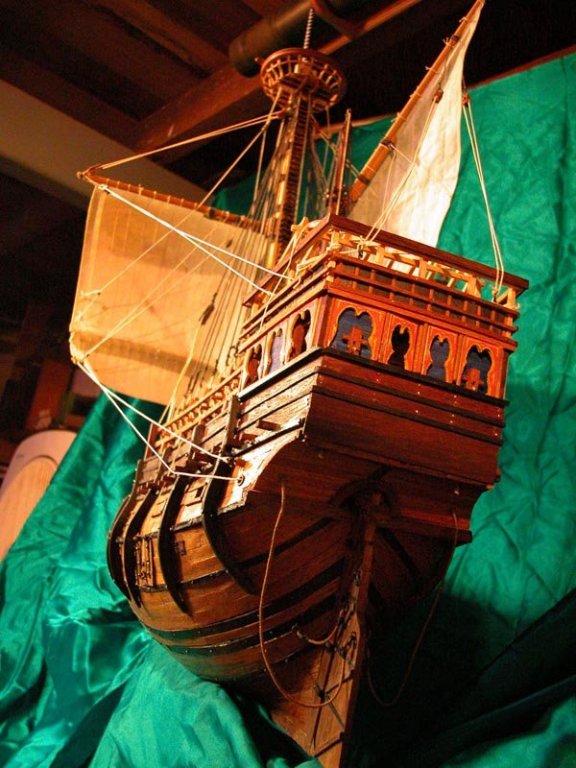
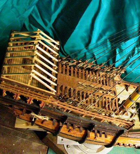
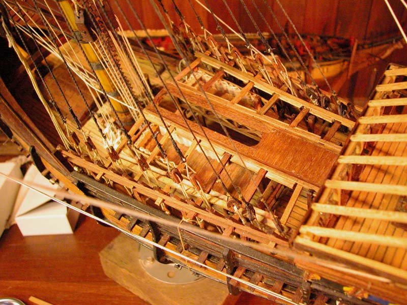
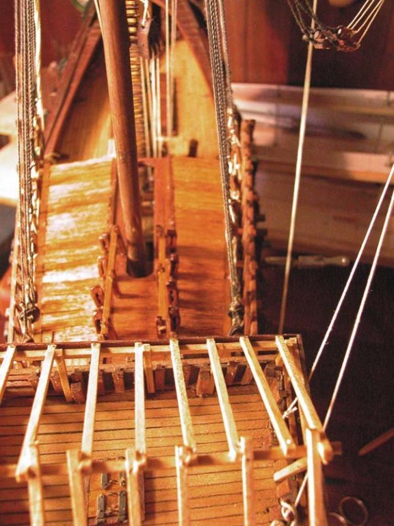
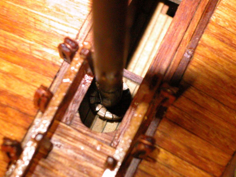
Thanks, Michael. I fear that a nautical academic would regard my model as a good speculative decorative model and no more. I am awaiting publication of the Black Sea wrecks recently discovered which will change many of our ideas about mediaeval vessels. I have redone the decking of the accommodation in the half deck (which was also used by the crew for access to the main shrouds and mizzen rigging). I have extended the decking out almost to the gunwales (if you can use the term gunwales in this pre-cannonic era) so the crew can now reach and adjust the main shrouds. the half deck as before the framing extended out beyond the gunwales I have then installed the mizzen mast . Please note that the rigging of the mizzen lateen sail will follow the "mediterranean" method whereby the sail is led outboard of the shrouds (see Landstrom:The Ship"). The mizzen shrouds will next be hooked up decking completed and mizzen mast installed. Lower blocks in place for shrouds and bitts either side the wedges in place More to come soon. Cheers Dick

- 632 replies
-
- 11
-
-
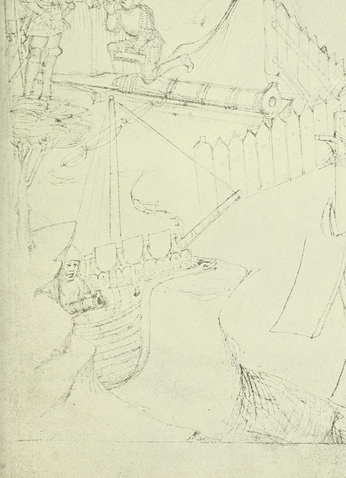
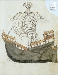
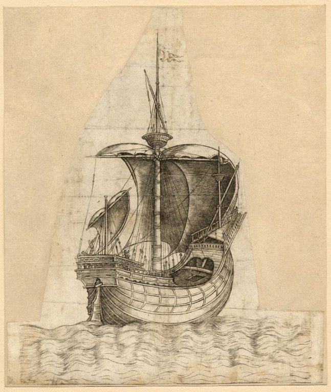
Thanks, Michael. I hope that the hull design makes sense. I think it is reasonably similar to the original sketch in the Zorzi Trombetta manuscript
-
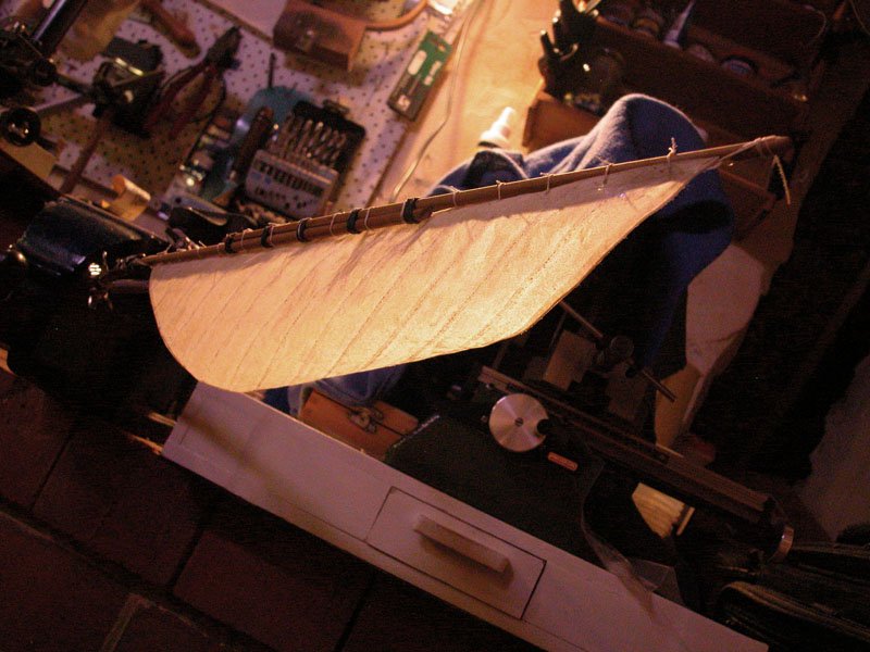
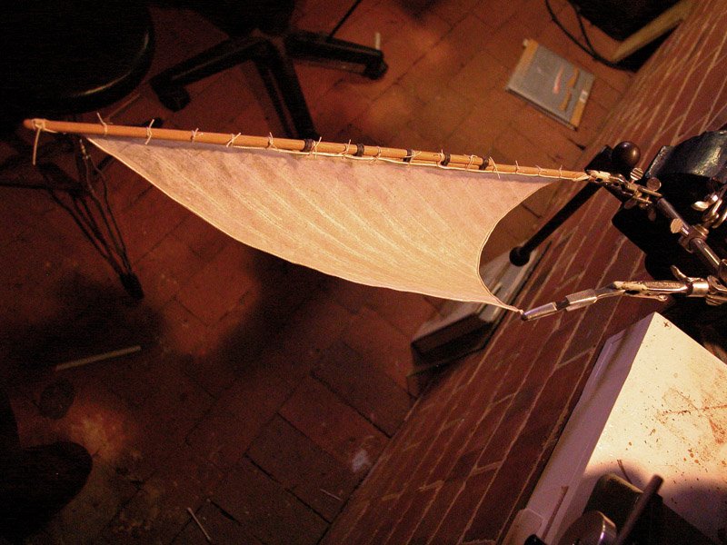
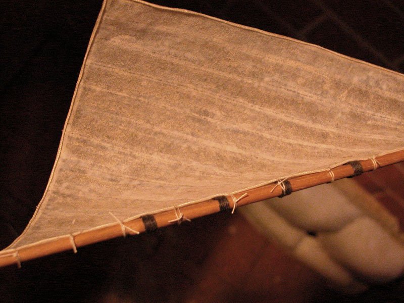
I am still learning to use it. The thin Silkspan which I used can be delicate and should be carefully cut ( I use a guarded razor blade). When wet it can tear easily. But the thin Silkspan really hangs well. Artists medium or matte varnish is a good adhesive and resists subsequent rewetting. I like the appearance of seams produced by Silkspan strips pasted over pencilled dashed lines. Silkspan is bright white and I find that cold tea produces a nice canvas like appearance. The staining should follow the application of the seams as this produces a slight bulging of the "strips" of sailcloth between the seams (if that makes sense). My previous deck over the accommodation in the half deck did not allow crew access to the shrouds. Some illustrations seem to show this as completely decked over right out to the sides but this cannot be so if the shrouds are inboard. I have a cunning plan which will work and is shown in the above picture Dick
-
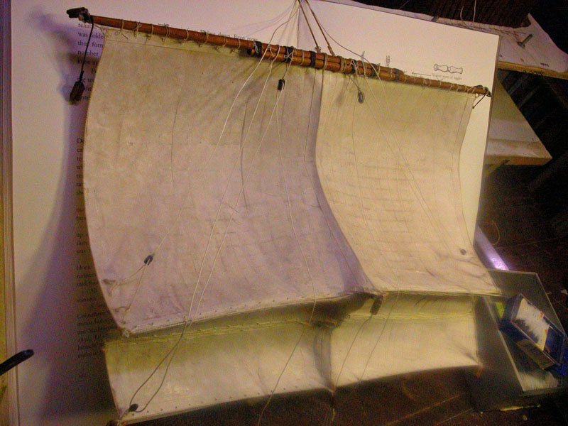
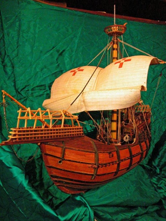
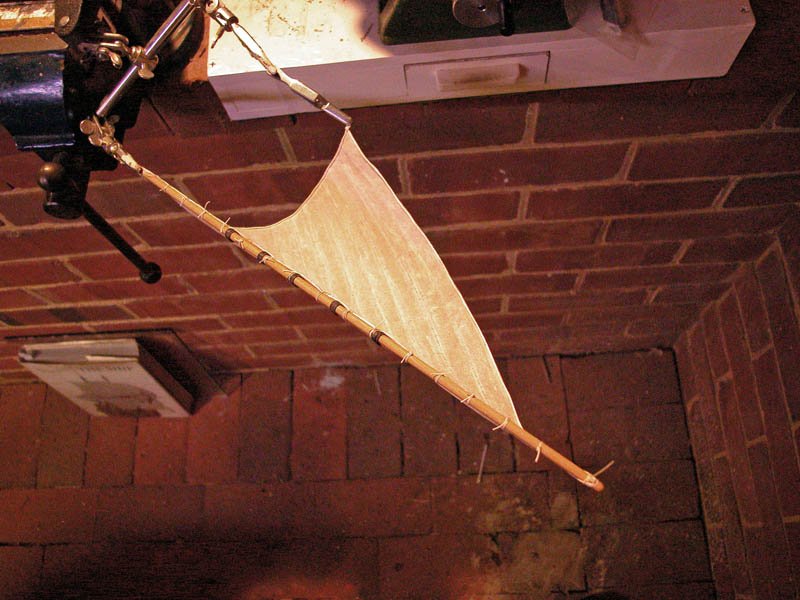
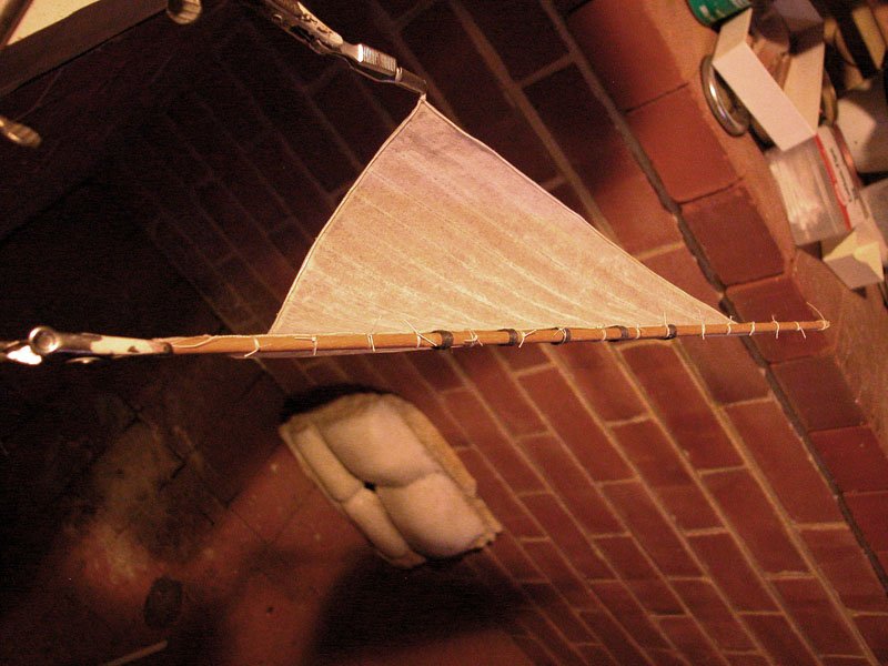
Apologies for being AWOL. I have been working on the mizzen rig and hope to finish it soon. The mizzen yard is almost as long as the mainyard but not so heavy. I have made the sail using Silkspan. I stained the Silskpan with tea. The sail structure was imitated using pencil to imitate stitching, overlaid with narrow Silkspan strips. The glue was artists matte varnish. Bolt ropes were glued on with wood glue. The sail was shaped and "doped" with the varnish to stiffen it. I have also had to rethink the half deck. More to come ............ the mainsail from below Merry Xmas all Dick

-
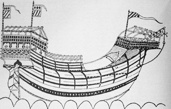
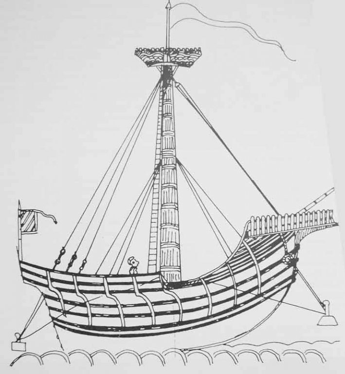
As I am part way through the building of the mizzen, I will persist and see what it turns out as. Thanks for the new pics, Steven, What was the provenance of the last pic, the four-master? It has a colonnaded covered walkway from the forecastle to the waist like the nave of Michael of Rhodes (a single-master by the way! He died in 1445). It also has at least two extra masts for what appear to be some sort of studdingsails!! Weird. Was it some sort of fanciful dream-ship? Or an experiment? the nave of Michael of Rhodes As you imply, I doubt Zorzi Trombetta would have sketched a humble coaster rather than a stately argosy of the Doge with all the bells and whistles. Dick
-
I have done a bit of pondering over the last several weeks while working on the lateen mizzen. It just does not seem right! The more I look at the model and the Zorzi Trombetta illustrations, the more I believe that this vessel should have ONE mast. Based on venetian contemporary illustrations (L R Martin: The Art and Archeology of venetian ships and boats fig 158 page 186) It would appear that only about 40% of seagoing merchant vessels in the Venetian fleet in 1445 had more than one mast. Also, looking at the forecastle in the Trombetta drawing, I cannot see how a foremast is practicable. As this illustration shows no masts and another carrack from the same book shows a single mast, I feel I should depict this nave as a single master. Later in the fifteenth century, mixed rig 3 masters became more usual Dick
-
Ancient shipwrecks found at the bottom of the Black sea
woodrat replied to Baker's topic in Nautical/Naval History
Fantastic! I have been waiting for this. One of the wrecks appears to be an at least 2 masted merchantman from the mediaeval period with stern castle preserved. I need more pics . I have congratulated Prof. Jonathan Adams, the director of the project by email. (But he never acknowledged, standard behaviour for academics, I find) Dick -
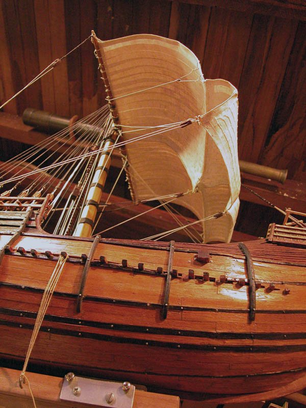
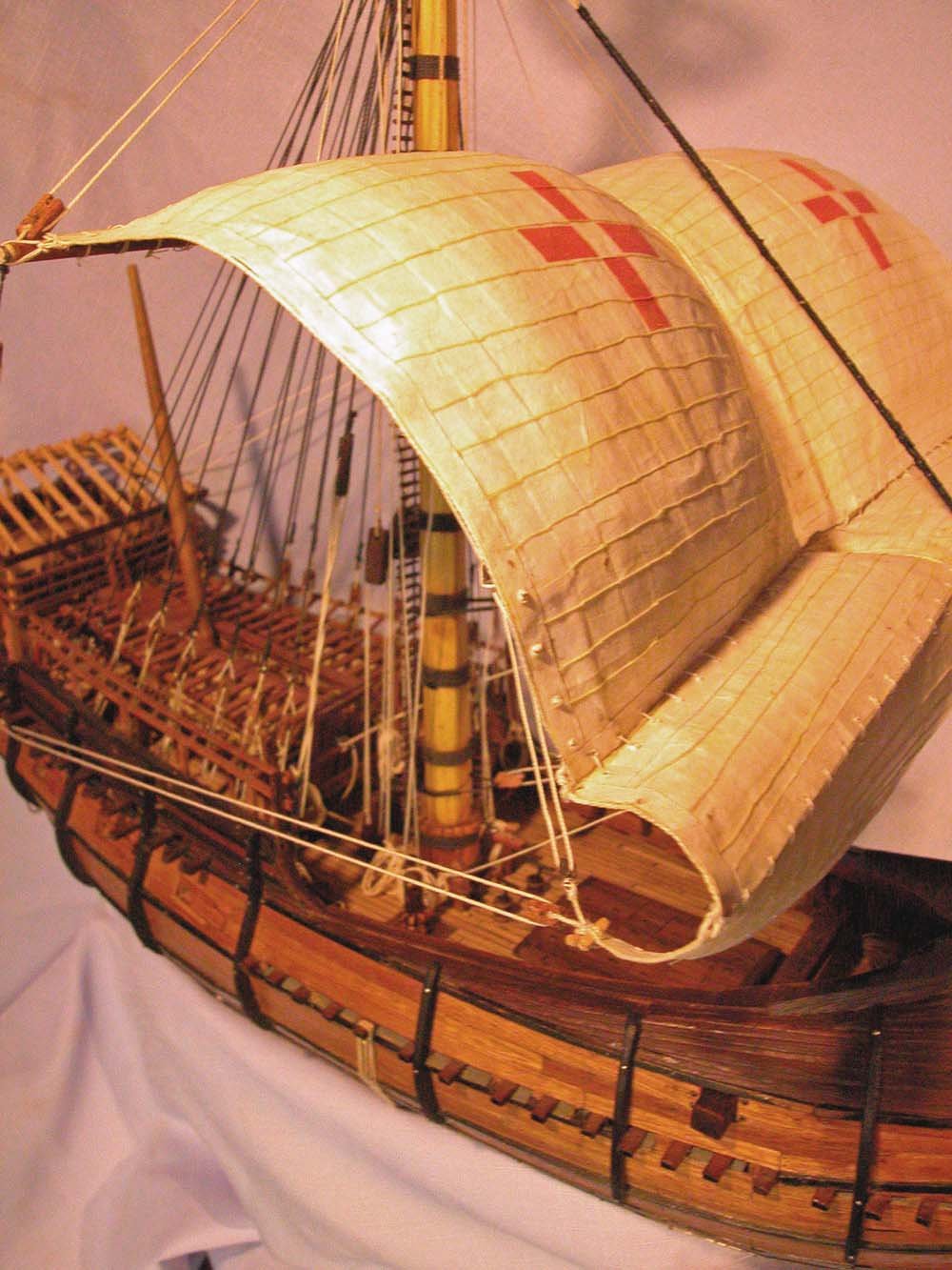
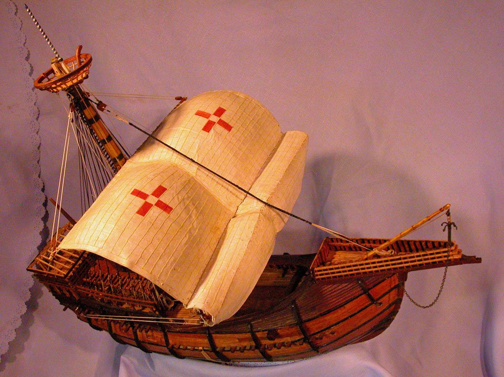
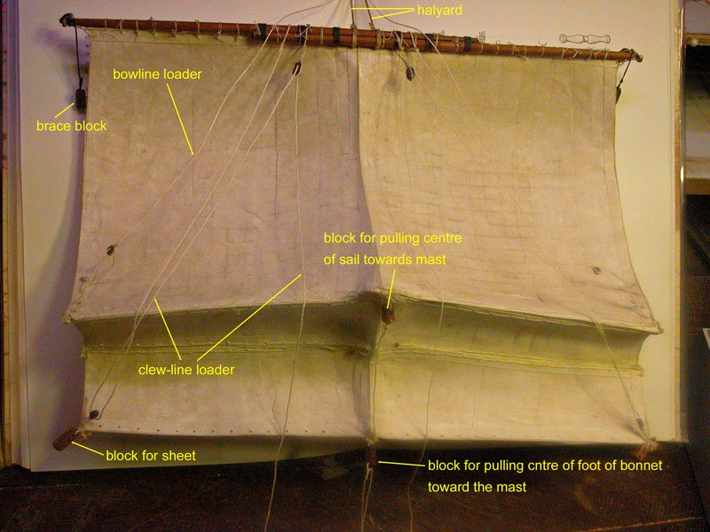
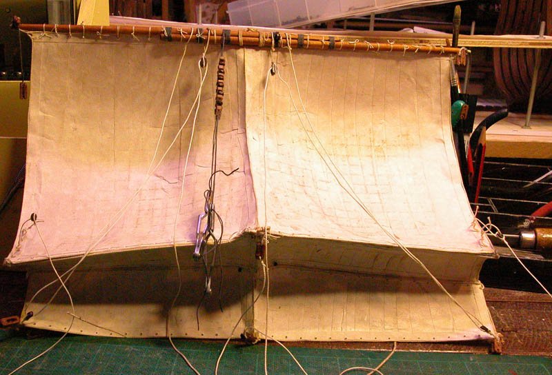
Thanks, Dan. The median "trench" in the mainsail is caused by a lanyard attached to a median boltrope in the sail (you can see two of these lanyards passing around the mainmast, one to the base of the mainsail and one to the lower bonnet). The purpose of these is to pull the centre of the sail in so as to prevent contact with the mainstay (note the wrappings, probably of leather or old sailcloth on the mainstay) and consequent abrasion of the sail. I have deliberately set the yard low as, in many illustrations, the sail billows upwards from the yard as a spinnaker would (please see Mark's valuable comments in the previous post in this regard). Mark, thank you for the sailing explanation. I had not thought that forward buoyancy would be so important. I think you are right. Your pic of the Sydney skiff shows the upward billowing of the spinnaker nicely. Cheers Dick
-
Thanks Roger and Carl. That clears it up for me. I will furl the mizzen and foresail in the interests of safety! Cheers Dick
-
Thanks Carl and Druxey. Now to the mysteries of the mediterranean lateen rig. As the ship is running before the wind, should the mizzen be furled? Some illustrations show the mizzen yard turned almost horizontal for running. But this may be because the vessel has the wind slightly on its quarter and the mizzen is being used for steering. Sailors please help. Others show it furled. Dick
_1465-1500_ca._11982_03_edited-2.jpg.520c68340d22e7f542ec06070c528bfd.jpg)
-
Indeed so, which is the clever part of parrels. The wooden bearings ride over the ropes like an all-terrain vehicle. Thanks for all the likes. Carl you wont have to wait long. Dick
-
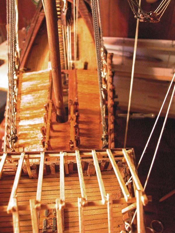
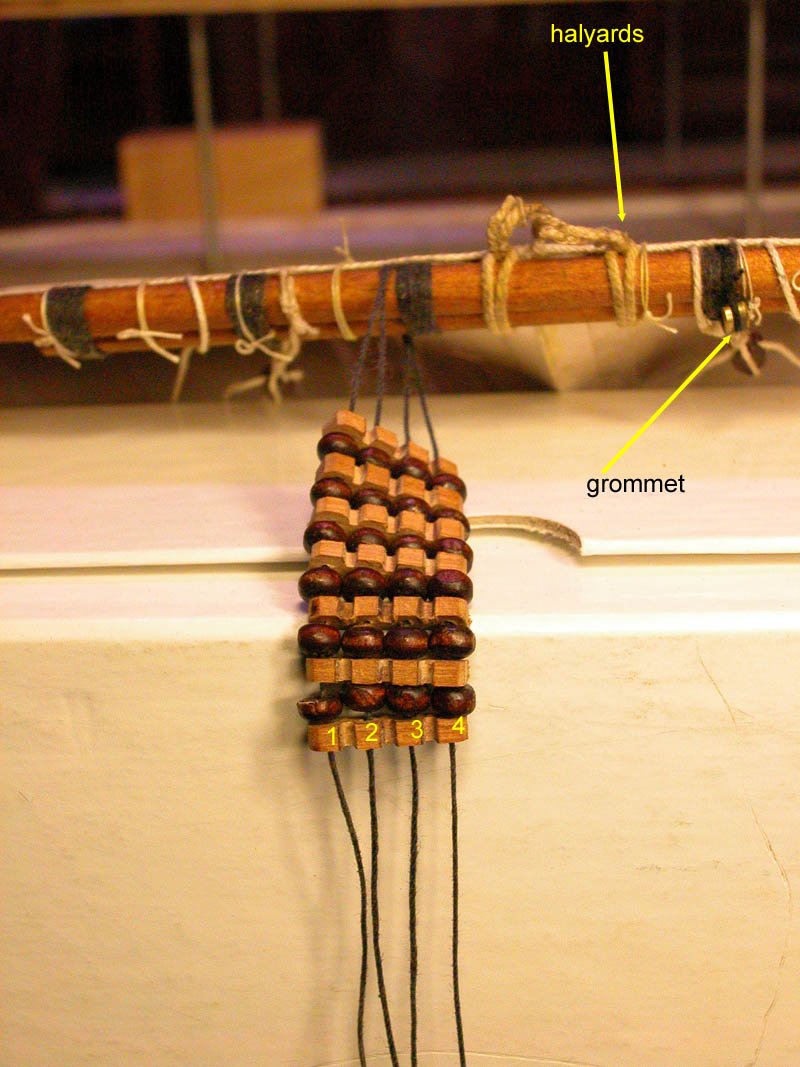
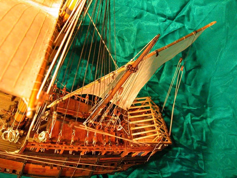
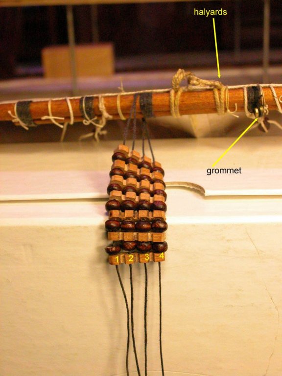
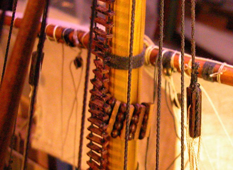
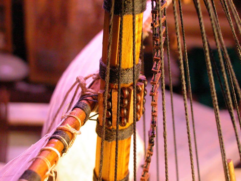
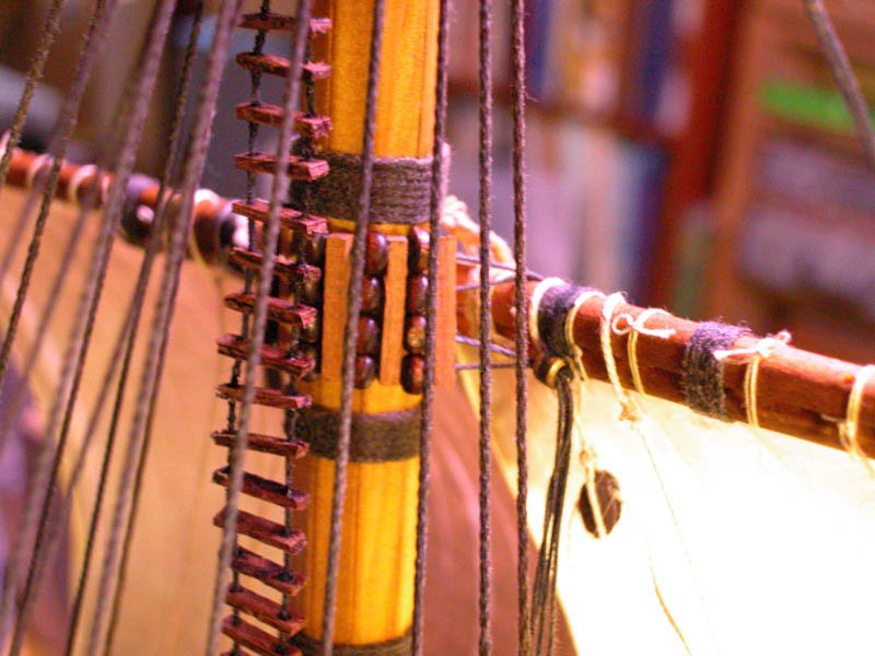
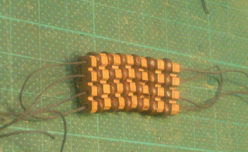
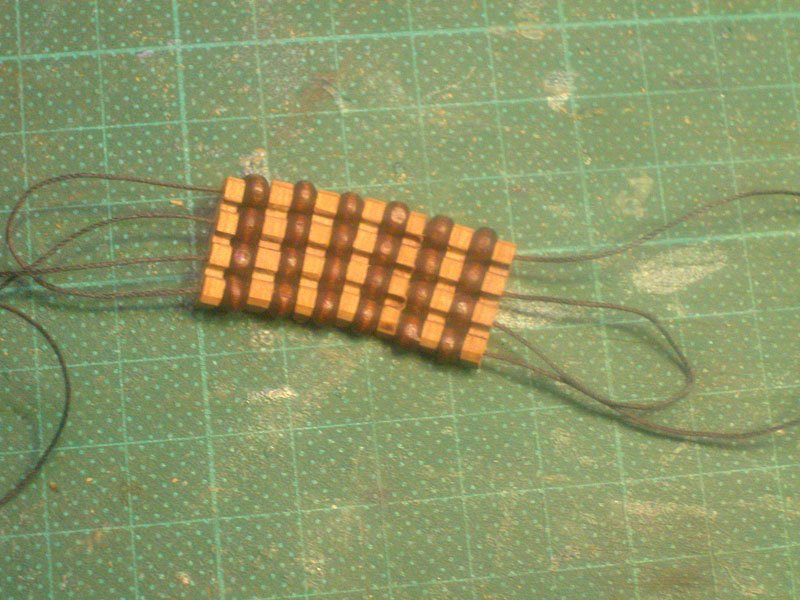
One of the more fiddly and interesting aspects of the rigging of this beast has been to work out how the parrels were applied to the mast. The excavated parrels from the Mary Rose were a great help in this regard. But I still had to work out a way of applying the parrels which I could understand and was consistent with the iconography. Firstly, in a large vessel such as this, three, four ar even more rows of parrels were needed. Secondly, any method of attaching them had to allow loosening and tightening of the parrels so that the position of the yard on the mast could be changed. In this regard, I recognise the wonderful work of Franco Gay ( The Ships of Christopher Columbus (Nuova Raccolta Colombiana, Vol. 7) by Franco Gay ) for his contributions . Thirdly, the parrel tightening needs to be done from deck level. The concept is my own modification of Franco Gay's method and seems to work. Grommet is seized to the yard. Its purpose is to transmit the parrel ropes to the deck. There are two ropes: one controls parrel rows 1 and 4 and the other rows 2 and 3 Please note that the slots end up AGAINST the mast The yard is now ready to be attached to the mast. The starboard ropes are now passed around the yard. Note the parrels are loose. All ropes are passed through the grommet The parrels are tightened. The time has come to hoist the mainsail. Dick
- 632 replies
-
- 15
-
-
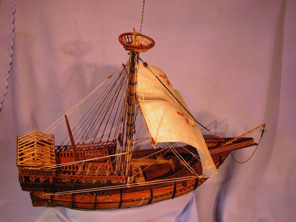
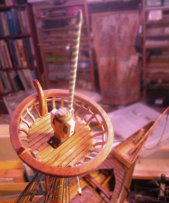
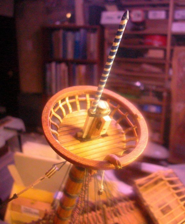
Thanks, Steven. The dromon is looking great! Here are some pics of the the parrels and the flagstaff. I have decided not to fit a topsail as they probably did not appear until about 1460. Also, no-one is sure how they were rigged. Cheers Dick

- 632 replies
-
- 13
-
-
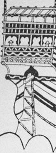
I cant recall seeing illustrations of navi from that time with stern ladders, plenty with side ladders. But I suppose anything is possible. With the very tall sterncastle it would be a long climb to the poop! Dick
-
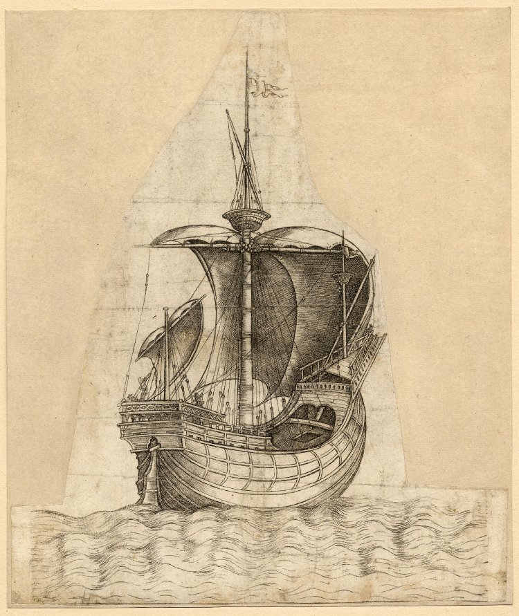
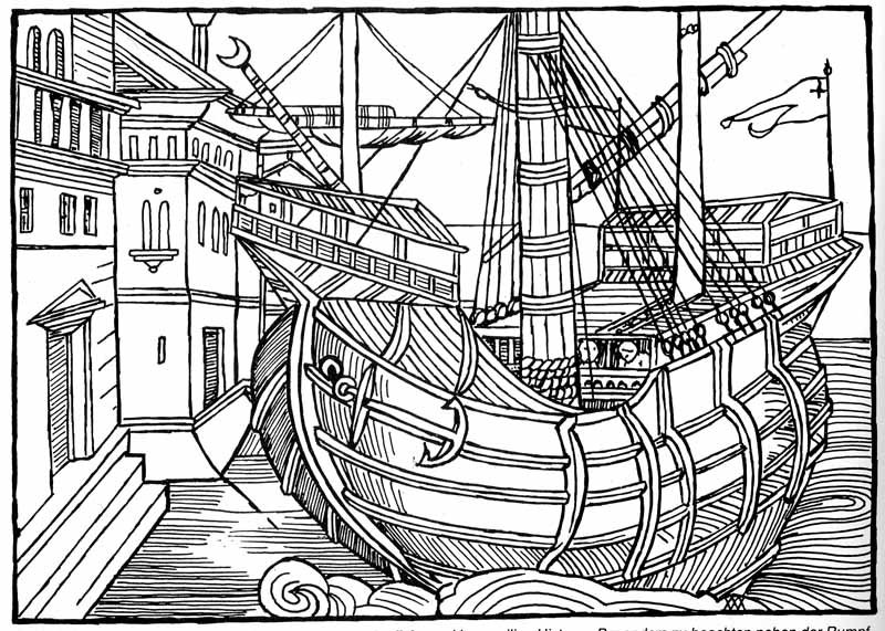
This seems to be a 19th century print of a small carrack. The ladder is well shown I presume they had stern ladders to access boats.