Kris Avonts
-
Posts
113 -
Joined
-
Last visited
Content Type
Profiles
Forums
Gallery
Events
Everything posted by Kris Avonts
-
Hi Ben, For you and anyone interested I can share the python source code. There are some comments written in the code file that can explain the order of things and the calculations done. If you encounter difficulties or other unclear parts in the code you can always send me a personal mail. This is the code file: ship-plan-adjuster.py best regards, Kris
-
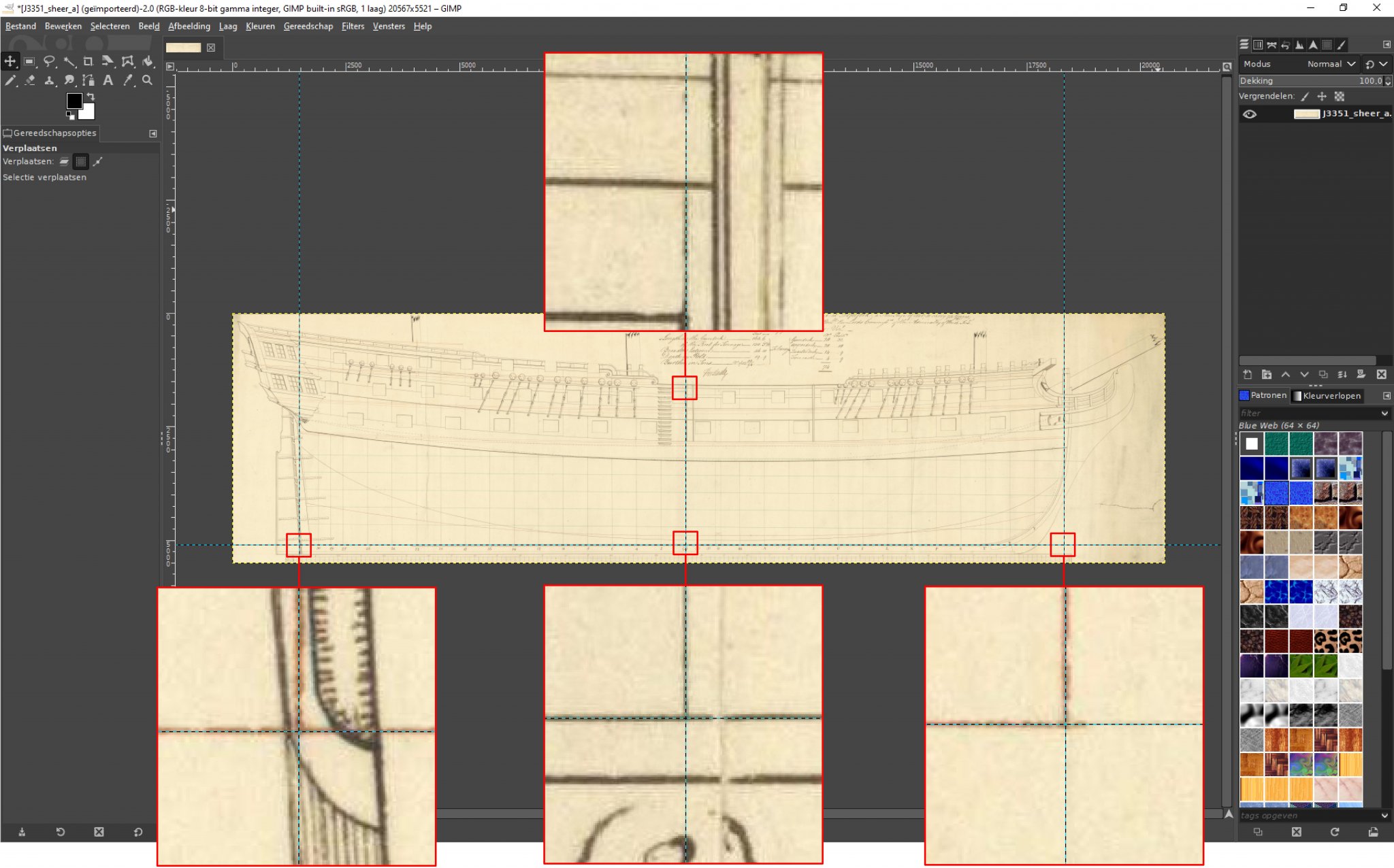
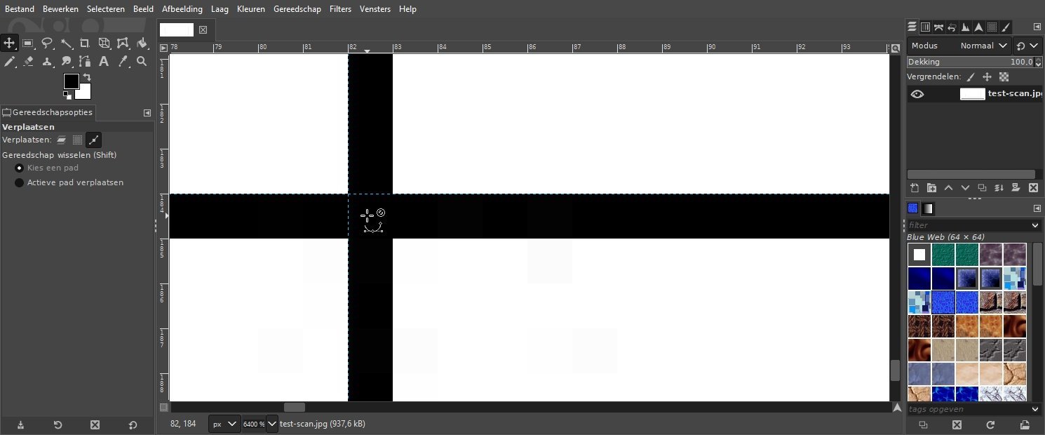
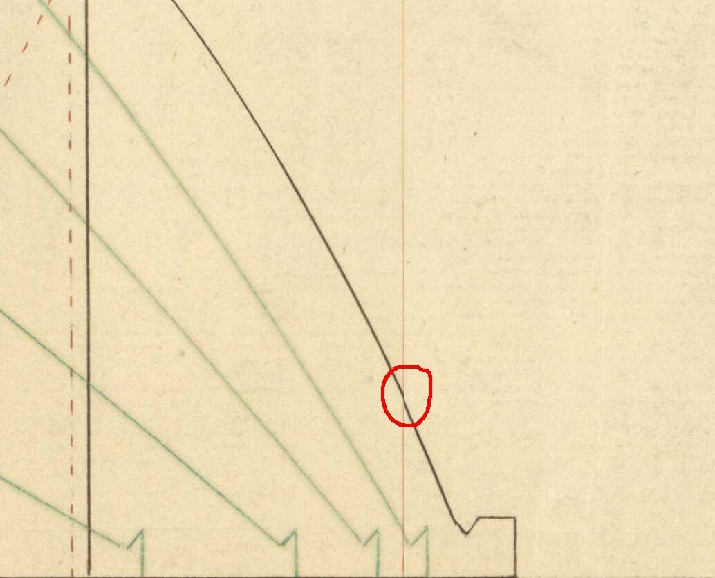
Hi Ben, Thank you for the appreciation of my image transformation program. It is however less advanced than you might think. I like to keep things as simple as possible but still try to reach the target I have in mind. A checkerboard correction method would only be applicable in the sheer view where you have the waterlines that should be straight and equidistant. The complexity of the transformation would become much higher and have no effect on the half-breadth plan where the waterlines are most important to give a representation of the ship's lines. Only when you could combine the intersection points of waterlines with station-planes of all 3 views (that is a lot of points) to map exactly on the same 3D point (most often called a vertex) by a transformation it makes sense. I think that is best solved in a 3D modelling program. @druxey, the ship plan scans of the RMG are such high quality, I think there is very little lens distortion. The paper distortion is more a concern and very difficult to correct due its irregular nature. I use my own transformation program to get the 3 views out of a ship plan and have them properly aligned before importing into a 3D drawing program. The workflow to make the transformations is important as I noticed in this detail of a half-breadth plan. I always try to analyse what could cause such artifacts. In this case it is not a bug in the transformation program but just me wanting to do correction of the half-breadth plan in just one go (single warp transform) instead of a 2 step square and warp transform. So you need to plan carefully the steps to follow, certainly when reusing results from previous transforms in other views (sheer in this case). best regards, Kris
-
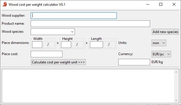
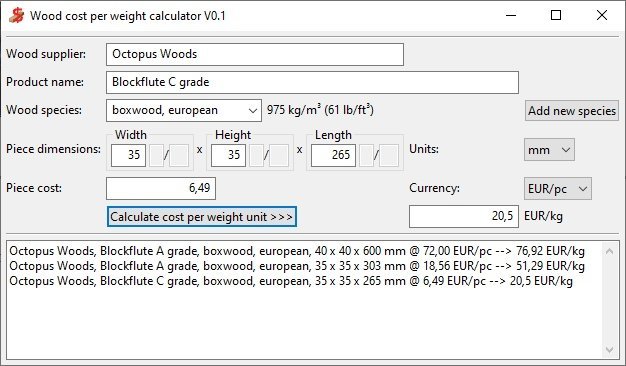
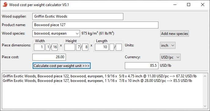
Hello all, Many topics in this wood discussion forum relate to finding the precious wood we all like to use for our ship models. It is not only difficult to find a supplier but also not easy to compare the cost of different offerings. So, I thought about making a small app that can calculate the cost per weight unit for a specific piece of wood. That makes comparing cost per kilogram or pound a little easier. It looks like this: The first 2 items ‘Wood supplier’ and ‘Product name’ are not used for the calculation but it can come in handy to remember later where your found what. Next you need to select the wood species of the piece you want to make the calculation for. There are some wood species already defined in the wood-cost.cfg file, but you can always add some more using the ‘Add new species’ button. Then it is time to enter the dimensions of the piece. Although it looks complex at first sight, I tried to make entering the numeric data easy. You can only enter digits and a decimal separator. You move to a next field with the TAB key. If select inch for the units then the additional fields for entering fractions get enabled. You can mix inch fraction with inch decimal dimensions. As a last item you enter the cost of that piece of wood and check that the currency selection is the correct one. Clicking the ‘Calculate cost per weight unit >>>’ will then display a cost per weight value for that specific piece of wood. And in the output window below a summary line for that piece will be added. Better then much explanation, I can show what it looks like when used in Europe: And this is for the English speaking users: You can see that there can can be significant cost differences based on size and/or wood quality. I add 3 files that you can put in one folder of your choice. A double click on the exe file will start the calculator. wood-cost.exe wood-cost.cfg plank.ico I hope it helps you making the right choice when ordering some ‘costly’ wood. best regards, Kris
-
- 3
-

-
Hello Waldemar, Thanks for sharing your results with my transformation program. It can be a help before you start CAD work. My program uses the 'Python Image Library' also known as 'Pillow'. It supports a large amount of image file formats: BMP, GIF, JPEG, PNG, TIFF, ... You can find more information here: https://pillow.readthedocs.io/en/stable/handbook/image-file-formats.html I did not try all these formats but only JPEG and PNG. @Dart, maybe you can explain in some words how you tackled the problem. best regards, Kris
-
Sorry guys, I have to report a bug in the program. When doing a distribute or warp action on an image and you do give the optional x coordinates Xd in the ship-plan-adjuster.txt file, then the program crashes. You can see that by the CMD window suddenly closing unexpectedly. There will be no output image file nor text file. I ran into this when I tried to warp a half-breadth view and reused the Xd data that was calculated in a previous warping of the sheer view. I already corrected the program and changed the version it reports to 0.3 (mentioned on the first line in the CMD window or the output text file). Here is the update: ship-plan-adjuster.exe Hopefully it didn't cause much frustration yet. best regards, Kris
-
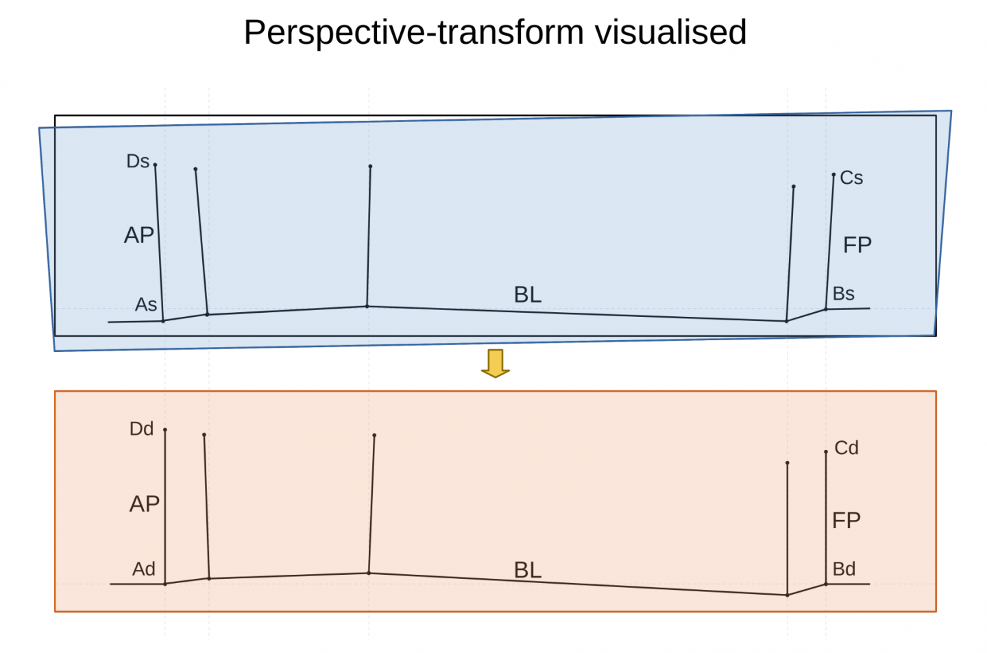
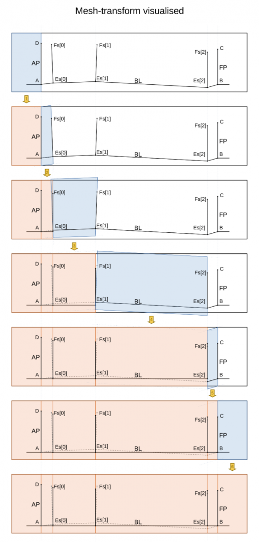
Just some addition about the transforms that are used. The first step is always a perspective transform and that does exactly what its name hints. It corrects the perspective view in 2D of a given object. It is especially useful for aligning features in an image of which you know that they should be vertical or horizontal. I made the following illustration to show how it is used to get the base line of a ship plan horizontal and the perpendiculars vertical. The transform squeezes the blue quadrilateral (figure with 4 sides and 4 corners) into the red rectangle. As you can see at the edges, the blue quadrilateral extends beyond the original ship plan image (black rectangle). That will cause points in the red rectangle that will not get a transformed pixel. These will get a fill colour that will be close to the average background colour. The next problem to tackle is flattening the base line and setting some stations vertical. That is a perfect task for a mesh transform. In the Pillow image manipulation library it is described as a series of quad transforms that are done one after the other on the same image. Now we must explain a quad transform, .... well that is just a transform which again maps a quadrilateral into a rectangle. Lets make it more clear with a next illustration. Here you see all the different quad transforms numbered from 1 to 6 that take place for a flattening action when Es and Fs each have 3 coordinate values. We start at the left side and map a blue rectangle with the aft perpendicular as its right side to the red rectangle that has the same size. This is actually a copy. That part was already corrected by the previous transform. Then the real work starts: the next quadrilateral has a left side that is taken over from the one to its left, the right side is a line passing through an Es, Fs pair, the top and bottom sides are parallel with a line through A and Es[0] (or Es[0] and Es[1], Es[1] and Es[2] ....you get the point). It is transformed to the red rectangle with its right side passing through Es[0] (or Es[1], Es[2] ...). The same action is repeated until we reach the fore perpendicular. The remaining part is again a simple copy. Then we are done The warp transform is a sequence of a perspective transform followed by a mesh transform with the one exception that the right sides of the red rectangles will not be defined by the Ls points (same as Es shown in the illustration above) but by distributed x coordinates Xd that are calculated by the program or given as extra input by the user. I did not include any math here to keep the description as intuitive as possible. For those who want a more closer look to the illustrations, I provide here also the pdf version where you can zoom for details. perspective-transform.pdfmesh-transform.pdf That is it for now. I hope that takes away a bit of the hocus pocus by just clicking an exe program. Best regards, Kris
-
Thanks druxey for your trust in my programming skills. I must however admit that some ship plans are a bit to complex to benefit from the auto distribution calculation for the stations. During the development I also tried the sheer view of the Hayling Hoy, but that was no success. I guess it was not designed according a 'room and space' rule. I know it is not a Royal Navy vessel. In such cases you are on your own. But with the help of a spreadsheet program you could check and eventually correct station distances by entering the optional destination points Xd. If there is some interest in what happens behind the scenes in the program, I could give some more information showing also the (simple) mathematics that come to the rescue. best regards, Kris
-
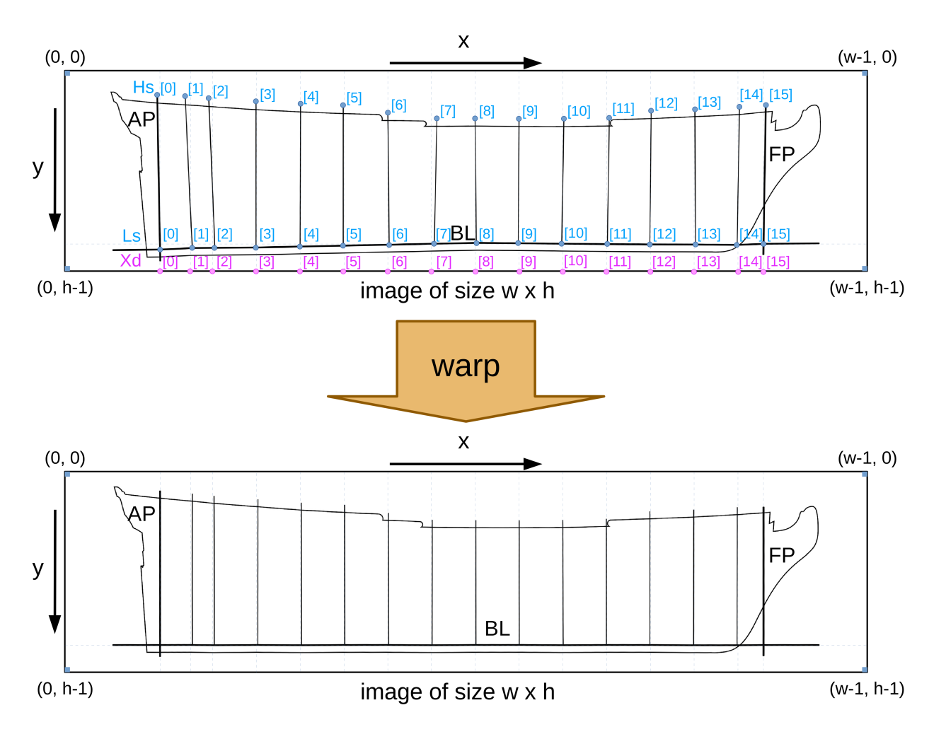
Hello, It's time for an update. The past weeks I worked further on this program and added several new features that can make it easier to do a transformation. In my previous post I promised to include a workflow to do a 'flattening' action for the base line. The several steps described in that post are now replaced by a single mesh transform. That is a transformation that maps a series of quadrilaterals onto a series of rectangles. This solves the problem of stitching the different parts that was present as the last step in my original workflow. I will not go into every detail for using this new version of the program here because I have made a user manual. ship-plan-adjuster_UM.pdf The name of the program was changed from scan-adjust into ship-plan-adjuster because that is just what I expect it to do. The most important addition is the 'warp' transformation that can do most of the work in one single step. The next figure illustrates what it is expected to do. For all details about this transformation, the points to input and how to use the program, please read the user manual. And here is the new program. See next posts for a more recent or less buggy version. ship-plan-adjuster.exe Although there was not much reaction on this topic I noticed it had quite some downloads. So maybe some of you can make use of it. If it serves your needs then it would be nice if you could show some examples here. Thanks in advance. As a last note I must warn that this program can not solve every issue that you may want to fix in a scanned ship plan. So always check the output image and reject it when it doesn't match your expectations. best regards, Kris
-
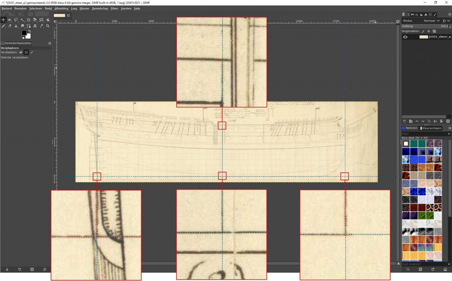
Hello again, While the result of the sheer plan adjustment with my scan_adjust.exe program was not bad, I noticed that it still has some deviations in the mid-ship area. The top of keel line on the plan was a little above the horizontal guide in GIMP that connects the intersections of fore and aft perpendiculars with the base line. Also some residual slant could be noticed for station (3). I wondered if that could be corrected using the same program. It is possible but it takes several steps: Divide the image in 2 halves with station (3) as the separating edge but allow some overlap (80 pixels) I named these J3351_sheer_a_aft.jpg and J3351_sheer_a_fore.jpg J3351_sheer_a_aft was adjusted with both source and destination points given: As = Ad, Ds = Dd, Bd 6 pixels below Bs and Cd 6 pixels below and 8 pixels right of Cs J3351_sheer_a_fore was adjusted with both source and destination points given: Bs = Bd, Cs = Cd, Ad 6 pixels below As and Dd 6 pixels below and 8 pixels right of Ds Then the 2 resulting half images and the original full image are opened as layers in GIMP. Shift the 2 half images until they stitch nicely (Bd and Cd of the aft half should map on Ad and Dd of the fore half) The layer on top (fore half in my case) will spoil the stitching because its edge has black (not transformed) pixels, so make a crop to get rid of these pixels Remove the layer with the full image and merge down what is left over That should give you a result with almost perfectly horizontal and flat base line and vertical stations. I do realise that this is a quite complex process just to correct for a mere 6 or 8 pixels. When I find some time, I may upgrade my scan_adjust program to recognise this special case and do all the required steps in the background and just saves the final result. Best regards, Kris

-
Thanks Jaager for spotting my typo. I corrected it before anyone else starts a search for that ship.
-
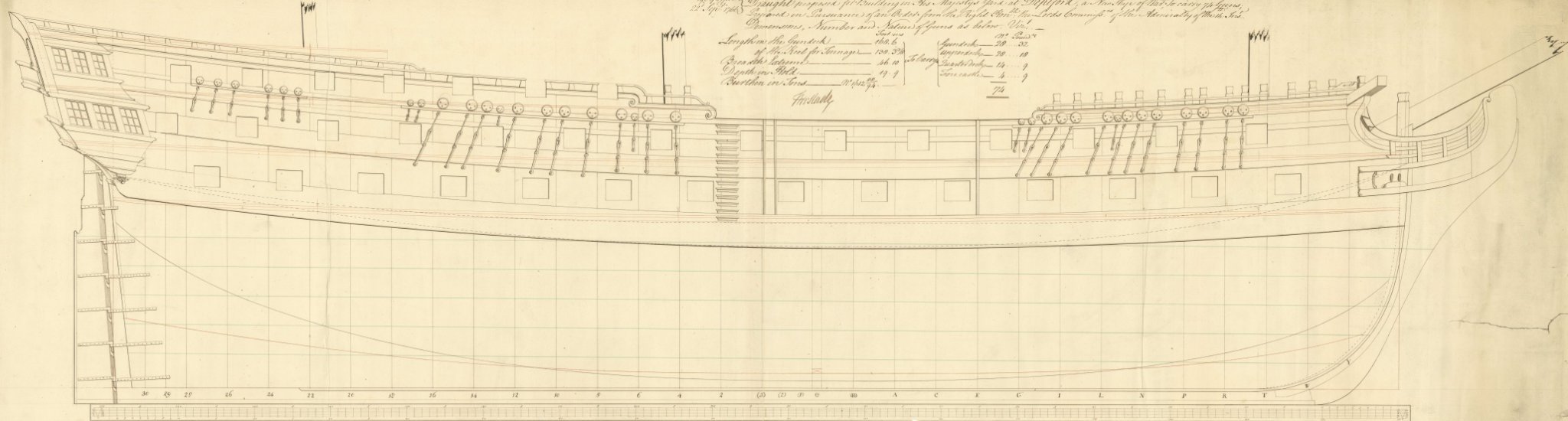
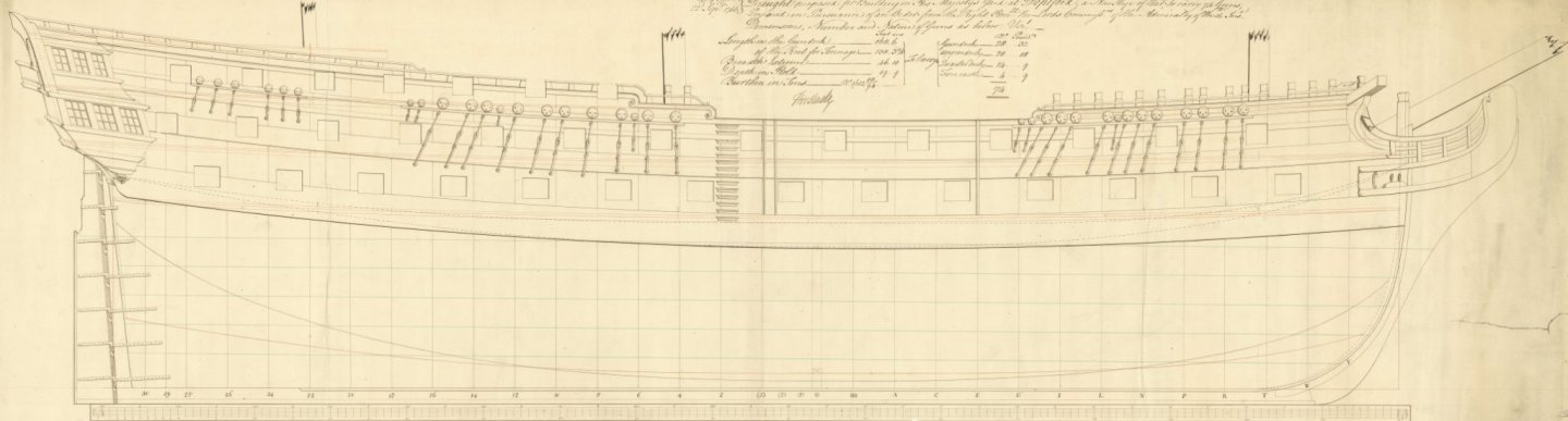
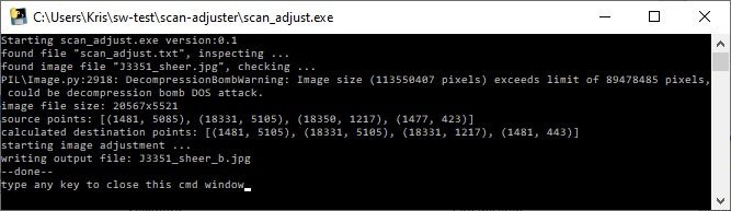
Hello Jaager, I’m very sorry that my post here gave you the impression that this program would solve any issues with misaligned or distorted plans. I wish it could. As for all tools or programs: garbage in is garbage out. The figures I added are more to illustrate the concept then to give a real world example. It should be used with care and a lot of scepticism regarding the resulting output. That is something I can not code into the program and is left to the judgment of the user. All of the ship plans I looked at until now are plans of the RMG collection. You can find a small fraction (3678 to be precisely) of these plans on the wikimedia commons: https://commons.wikimedia.org/wiki/Category:Ship_plans_of_the_Royal_Museums_Greenwich These plans are scanned and show high resolution but I suppose the alignment on the scanner was done with respect to the edges of the document and not its content. That is one of the reasons to make this program. I will show a real world example to demonstrate what you can expect from the program. I choose the file ‘Resolution’ (1770) RMG J3351.png and made a cut out of the sheer plan (shown below, reduced to 10% of its original resolution). It is a huge file (image size: 20567 x 5521, file size: 25.3MB) and it was also a test if my program could handle it. So I entered the required 4 source points and made a run. Apart from giving a warning that the image has more pixels than a preset limit, a result file (image size: 20567 x 5521, file size: 9.25MB) was produced. To show what the differences are, I opened the 2 image files as layers in GIMP. Then by toggling the visibility of the top layer while zoomed in on one of the source points you can observe the changes made by the perspective transformation. This is an animated gif made from 2 screenshots zoomed at point As (intersection of base line with aft perpendicular) before and after the transformation: The same for point Bs (intersection of base line with fore perpendicular): The same for point Cs (top of fore perpendicular): The same for point Ds (top of aft perpendicular): For me this is a reasonable improvement when using such scans as a background image in a 3D CAD program. And even then I never just draw over the lines but make horizontals, verticals and curves (splines) that are fair. Best regards, Kris

-
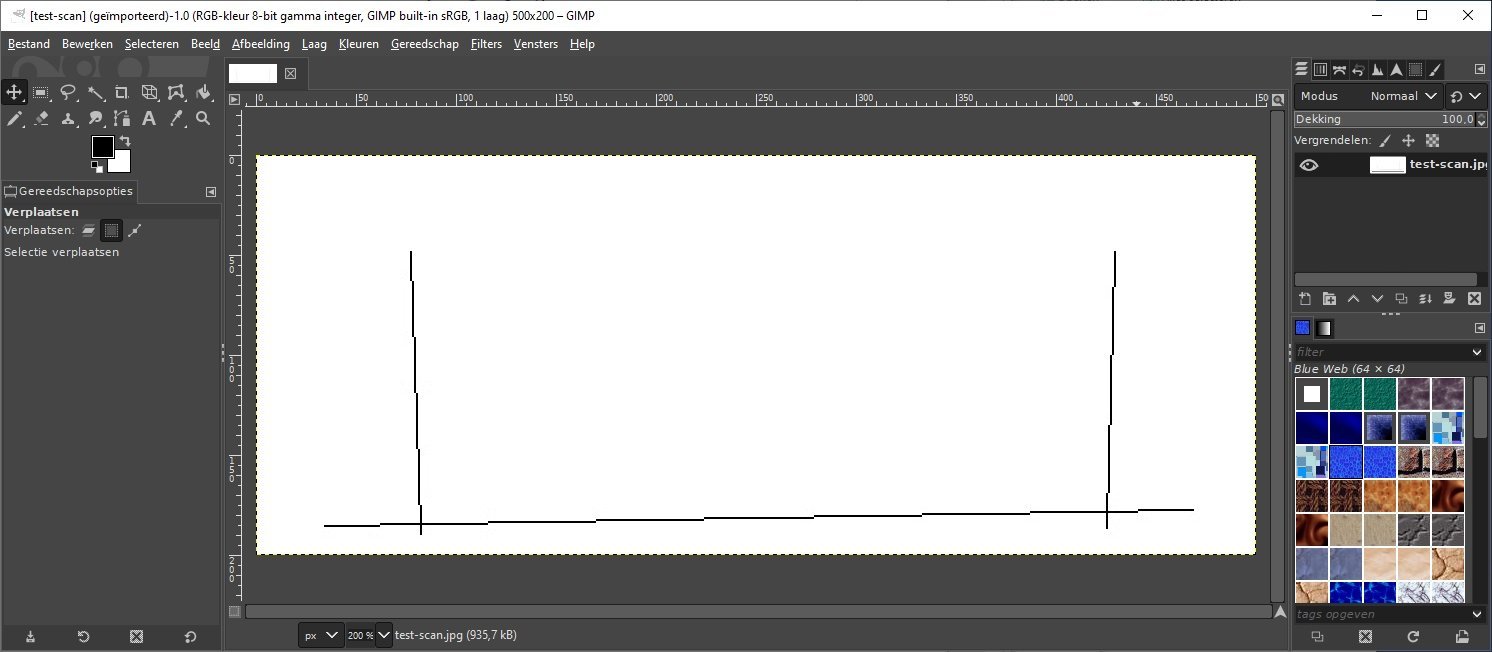
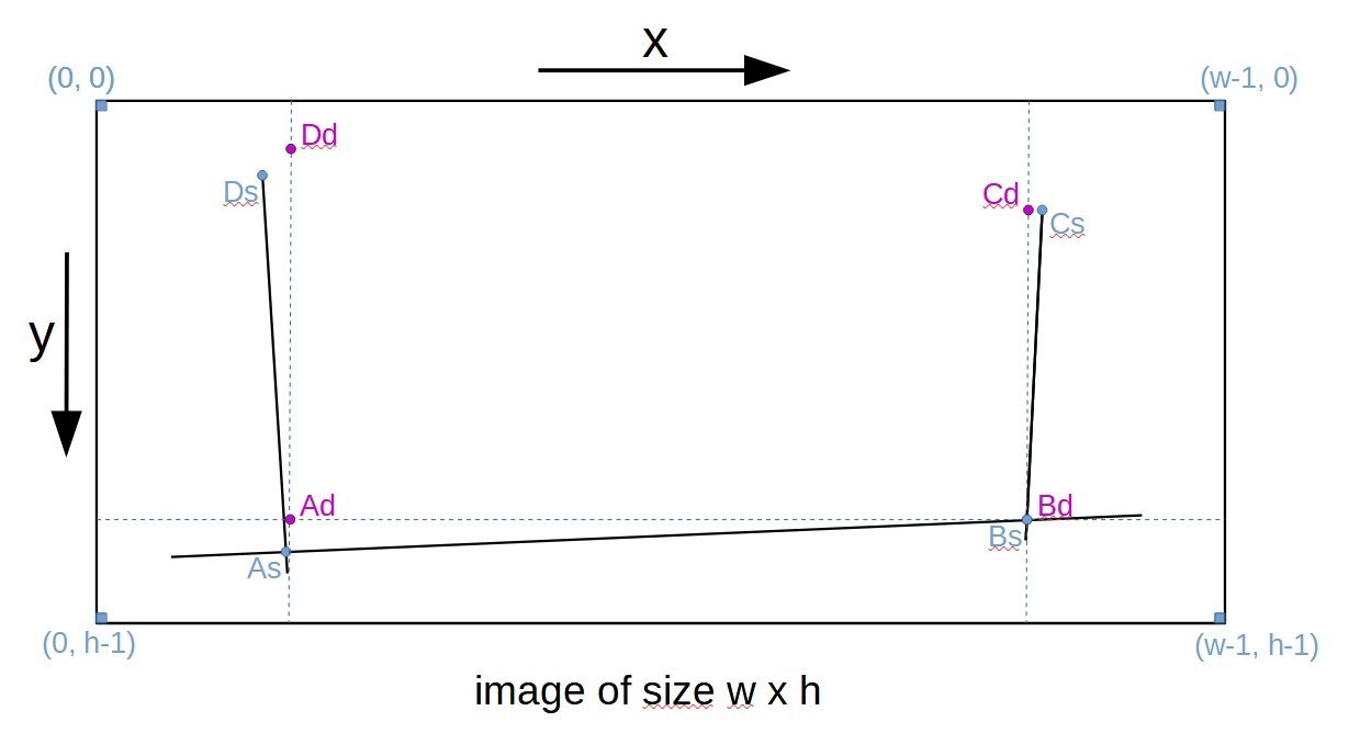
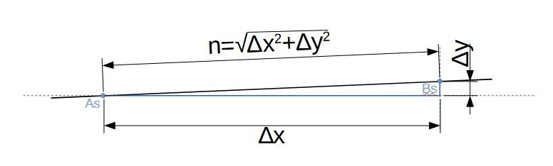
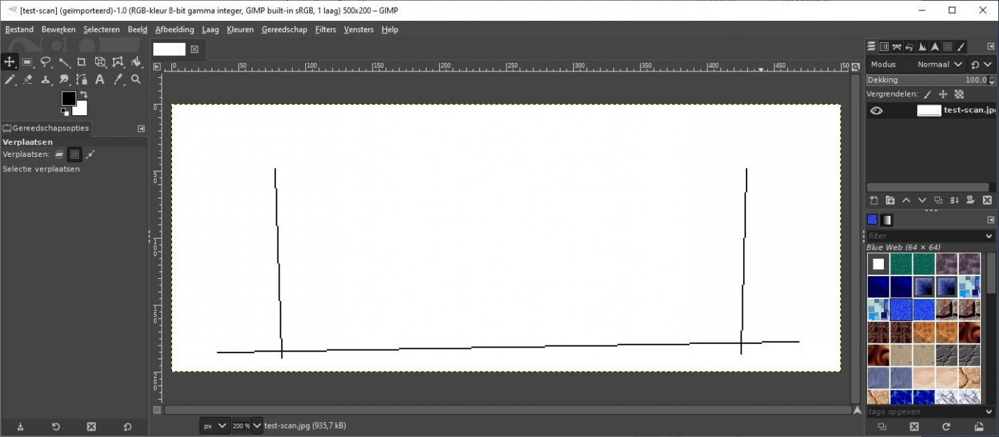
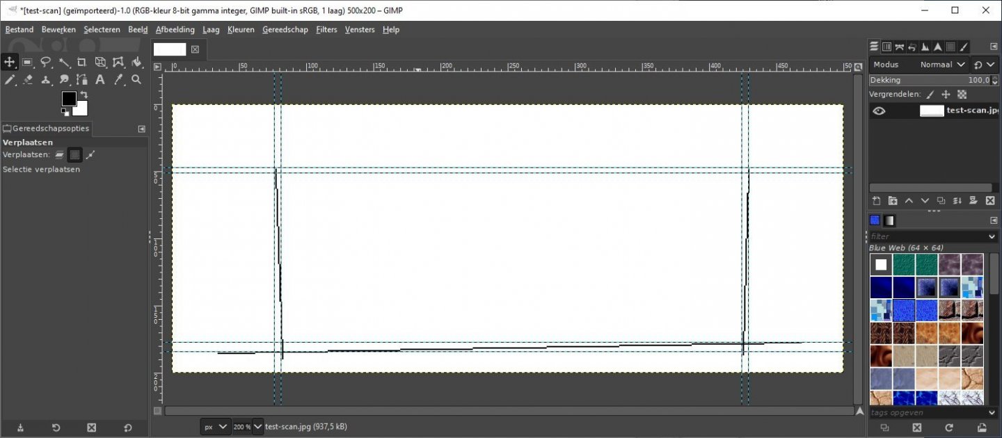
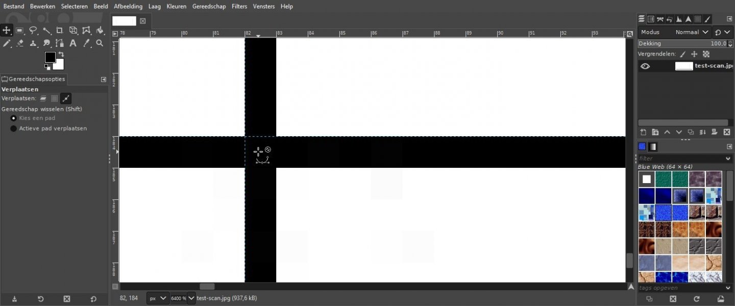
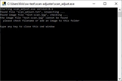
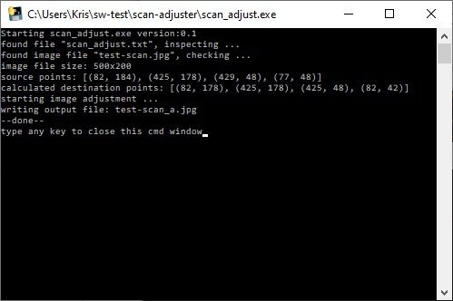
It’s time to give some update information and explain how to use the scan-adjust program. I developed this program mainly to fix misalignment and wanted as result a horizontal baseline (top of keel for 18th century ship plans) and vertical perpendiculars. So that is what I call the standard way to adjust a sheer plan. It is illustrated in the drawing below. You can see how the pixels coordinates are interpreted and where I intend to put the 4 source reference points: As, Bs, Cs and Ds. As is at the intersection of the aft perpendicular with the baseline Bs is at the intersection of the fore perpendicular with the baseline Cs is at the uppermost point of the fore perpendicular Ds is at the uppermost point of the aft perpendicular You may observe that these 4 points go round in a counter-clockwise direction and that they delineate a quadrilateral (a figure with 4 corners and 4 sides). The counter-clockwise direction is chosen because it is mentioned in the documentation for the used software (PIL, Python Image Library) that does the image transformation. These 4 source points need to be mapped to 4 destination points. You guessed it: Ad, Bd, Cd and Dd. You can also input these additional points to the program but if the adjustment you are after resembles the ‘standard situation’ then the program can calculate these 4 points based on the knowledge that Bd=Bs, Ad has same y-coordinate as Bd, Cd has same x-coordinate as Bd and Dd has same x-coordinate as Ad. What remains is to find the x-coordinate of Ad and y-coordinates of Cd and Dd. Well there we can make sure that the difference in x-coordinate between Ad and Bd is equal to the number of pixels between As and Bs counted on the line that connects As to Bs. That sounds like trigonometry and it is, see the illustration below. The calculation of n is used to determine the x-coordinate of Ad. A similar calculation yields y-coordinates for Cd and Dd. So all destination points are fully defined and the transform can be started. Next I explain how we enter the required data into the program. I choose not to develop a GUI (Graphical User Interface) for my program but simply to look for all required data in a text file that has the same name as the program file but a txt extension. So the program will be ‘scan_adjust.exe’ and the data file ‘scan_adjust.txt’. Next is shown the content of this data file as I used it for my initial test of the program. test-scan.jpg As=(82, 184) Bs=(425, 178) Cs=(429, 48) Ds=(77, 48) The next problem to tackle is how to get these coordinate values. Well there are very good image manipulation programs with very good GUI’s to zoom into images and by positioning a cursor where you want to set your source point (As, Bs, Cs, or Ds) will show the x and y coordinate values. You can note these down and then enter the values in the scan_adjust.txt file. I always use the GIMP program for this and next I show the steps I take to get these values. Open your image in GIMP and zoom so that the whole image is shown. Then add 4 horizontal guides (position your cursor in the ruler above the image window, click and drag down) close to the source points you intend to use. Now do the same for 4 vertical guides (position your cursor in the left ruler click and drag into the image) Now you can zoom into each source point and refine the positioning of the guides. Next is shown the final guide positioning for As. I set the horizontal guide above and the vertical left of the reference point. When you position your cursor just below and at the right of the intersection of the guides, you will see the coordinates to use for As at the left in the status bar below the image window (82, 184). Then do the same for Bs, Cs and Ds. Edit the scan_adjust.txt file with your image file name on the first line followed by the 4 source points. How to install my program? Just put it in a folder of your choice. Then add the text file and your image file in the same folder. Double click the scan_adjust.exe file and the transformation will start. It should bring up a CMD window that show some steps that are executed and at the end it waits until you press a key (this is just to help you read its content). The transformed image will have the name of the input image with ‘_a’ added (to refer to the adjusted status) or a file name and extension that you entered as last line in the data file. When something goes wrong, I try to give a meaningful message and keep the CMD window open until you press a key. Here is an example warning. And her is a successful run. Now I only have to provide you with the program itself. For a more recent or less buggy version see next posts. scan_adjust.exe Good luck with it and best regards, Kris

-
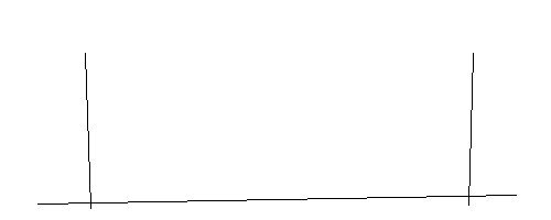
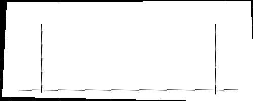
Hello, When using a scanned ship plan as a background image in a CAD program, it often shows some misalignment or even distortion. That makes it more complex to build a precise model out of it. I usually try to fix things with an image manipulation program (e.g. Photoshop, GIMP, …) using several transformations: rotation, scaling, shearing, … and even perspective corrections. That goes a long way to reach a perfect aligned plan but it is also time consuming and difficult to get it pixel perfect. So I made a little python program that can do a pixel perfect perspective transformation based on set of reference points that you define in the image you want to adjust. Let me show my first attempt with a simple test image. Imagine that this is a sheer plan with a base line at the top of a keel and a fore and aft perpendicular. The base line is not horizontal and both perpendiculars differ from a vertical with some (different) slant. After transforming it with my program it looks much better. The base line is now horizontal and both perpendiculars are vertical. The whole image is remapped using a transformation matrix calculated from the set of given reference points. That is why the edges now show misalignment and slant. The empty pixels at the edges (black) could be corrected by filling the pixels that fall outside the transformation with the background colour (white in this case). At this moment the reference points are hard coded into the program and the test image is also ridiculously small. So it will be of no use to anybody else but I will work and test a bit further until it is more user friendly and then I can upload it here for interested ship plan users. Best regards, Kris
-
Exploring FreeCAD for ship modeling
Kris Avonts replied to TonyM's topic in CAD and 3D Modelling/Drafting Plans with Software
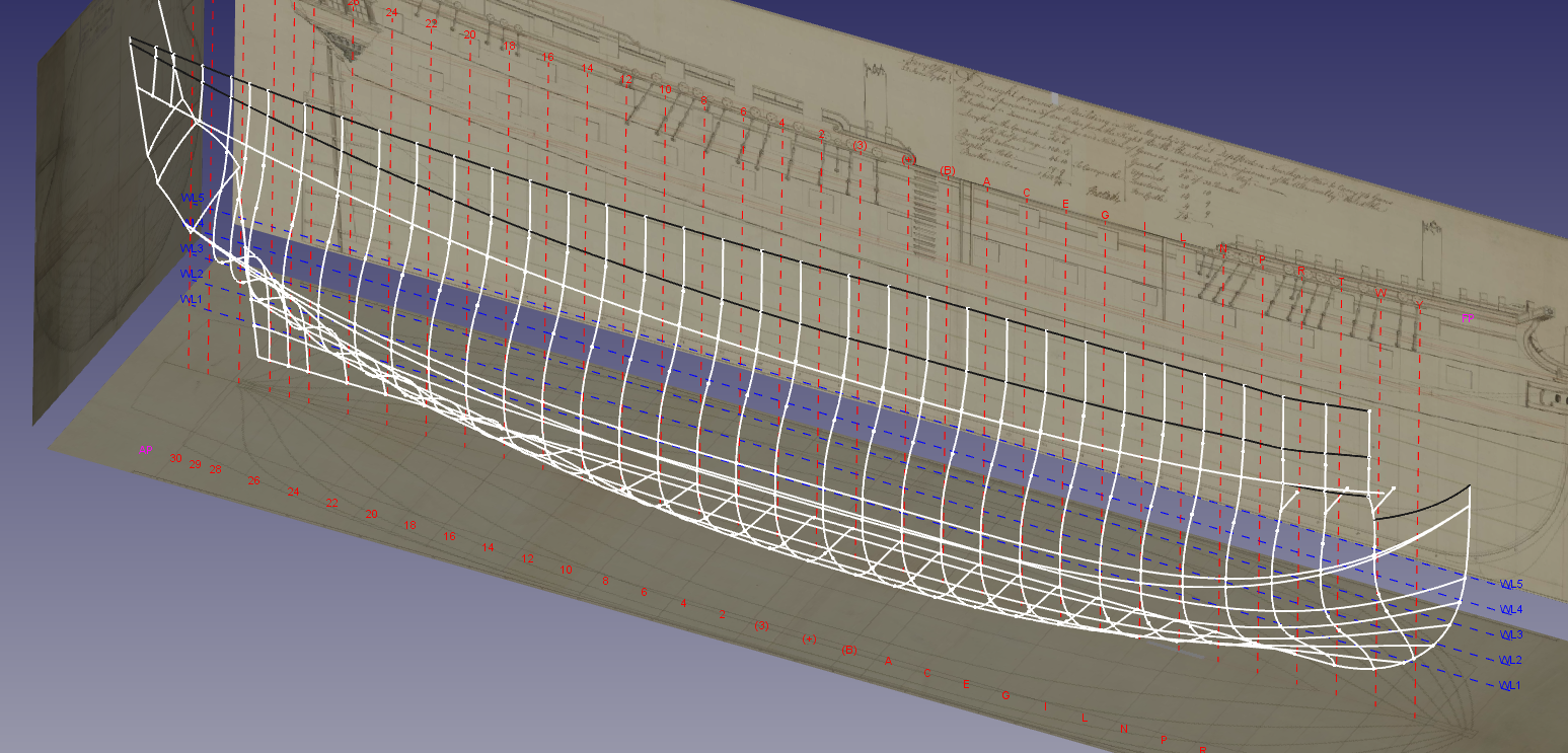
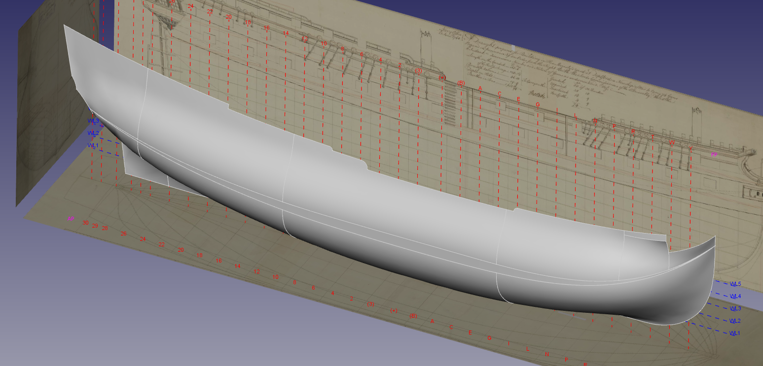
Hi Tony, Glad to see that you made such nice progress on your schooner. Sorry I didn't post some updates of my efforts to create a hull for a 74-gun ship. But last week I finally succeeded in making several surfaces that represent the hull quite well. Only at the stern it still has some 'wrinkles'. Maybe it is good enough to start lofting timbers. Here is the framework of stations, waterlines and other guiding lines made from sketches. And next you can see what the hull looks like based on the above frame. So, after all, it is possible to make a ship hull in FreeCAD.... ...but it requires significant effort and patience before a result shows up. I hope you succeed in all your detail work with the schooner. It is inspiring. best regards, Kris

-
Hi Kiyoo, This looks a nice and elegant way of creating the required lines for frame timbers. I'm however quite surprised regarding your effort estimation as you have given in reply to Druxey's question. If I look at my own efforts, I would rather spend months instead of days to reach that state. Well done! May we also get a clue about the specific drawing software (both 2D and 3D) that you are using? I'm a fan of FreeCAD, mostly because it is 'free' in every sense. best regards, Kris
-
Joinery
Kris Avonts replied to Maury S's topic in Building, Framing, Planking and plating a ships hull and deck
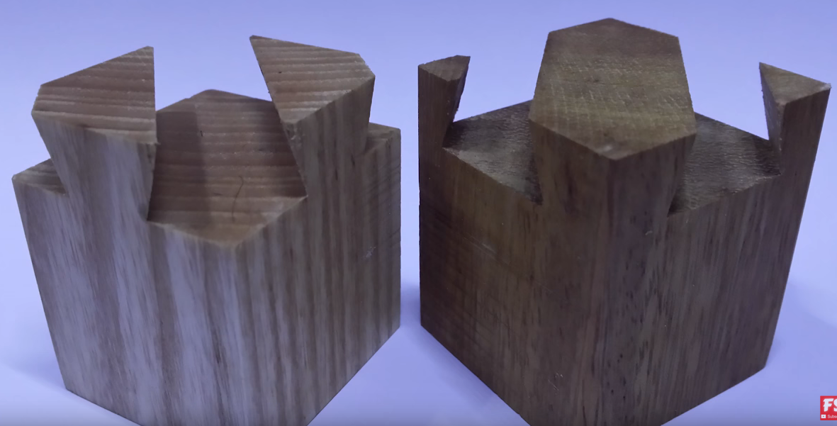
For me, it looks like a smart variation on the impossible dovetail joint. Anyway, it is fine craftsmanship. best regards, Kris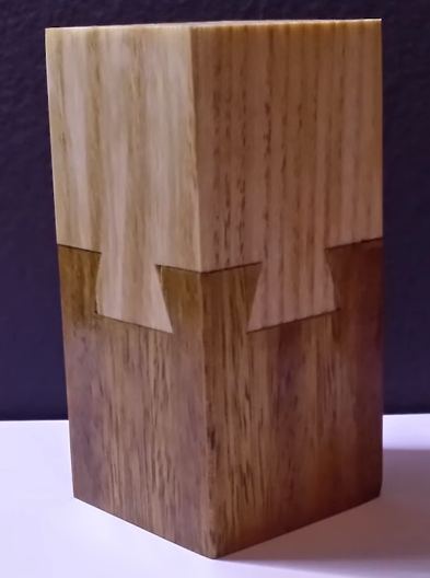
-
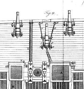
Hello ASlrWnt2C, As a first indication you can take a look at this picture which is part of plate IX in William Falconer's dictionary. The middle gun shown is run in as far its breeching lines allow. Maybe that can help you further. best regards, Kris
-
A DIY thickness sander
Kris Avonts replied to Kris Avonts's topic in Modeling tools and Workshop Equipment
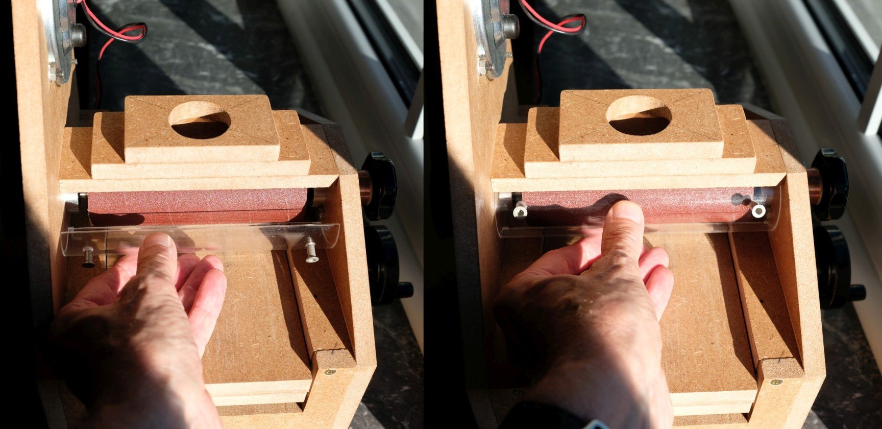
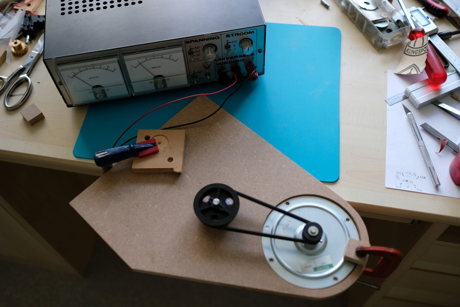
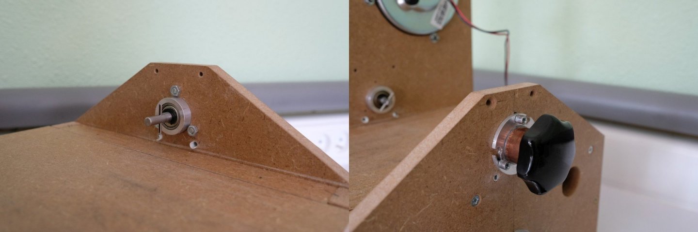
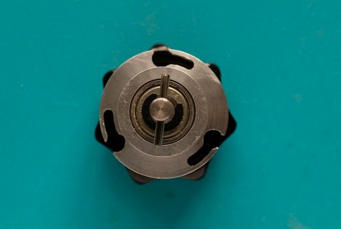
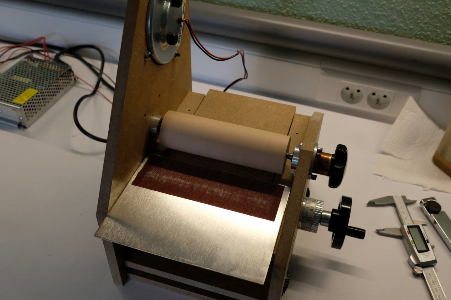
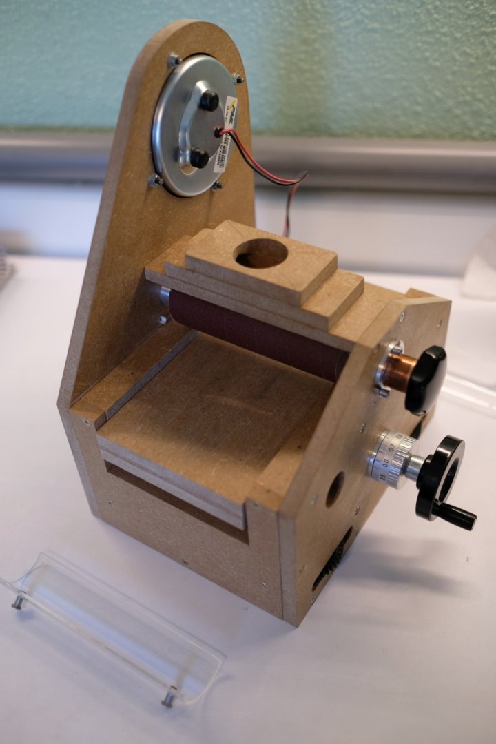
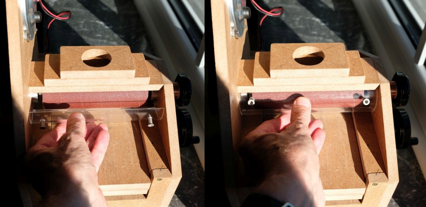
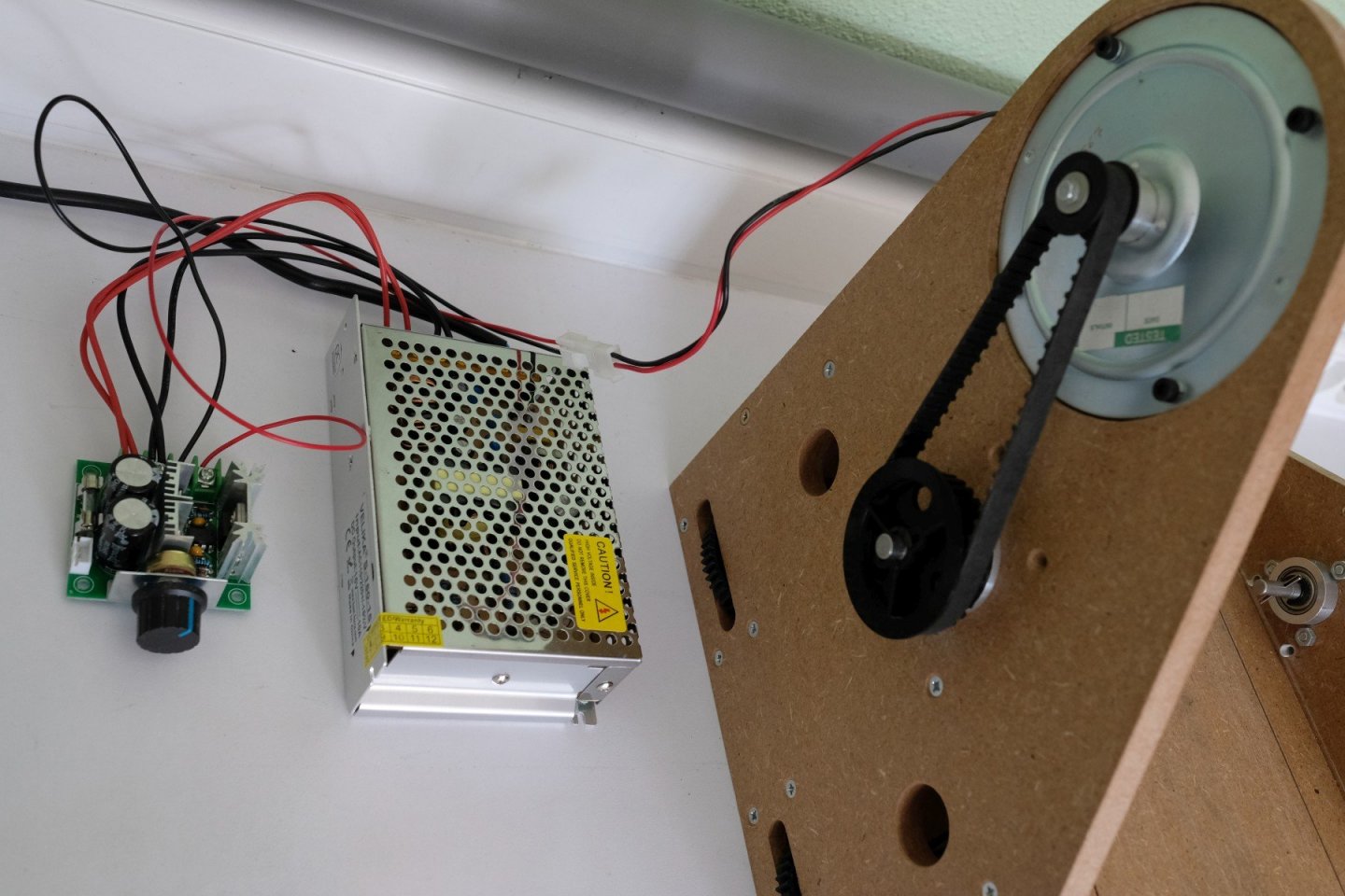
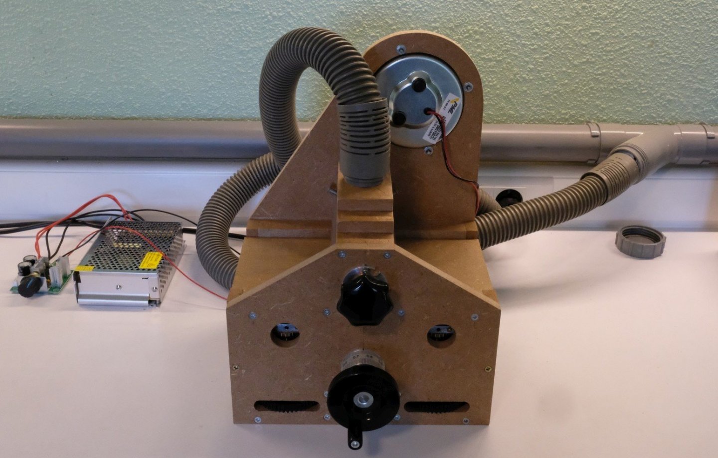
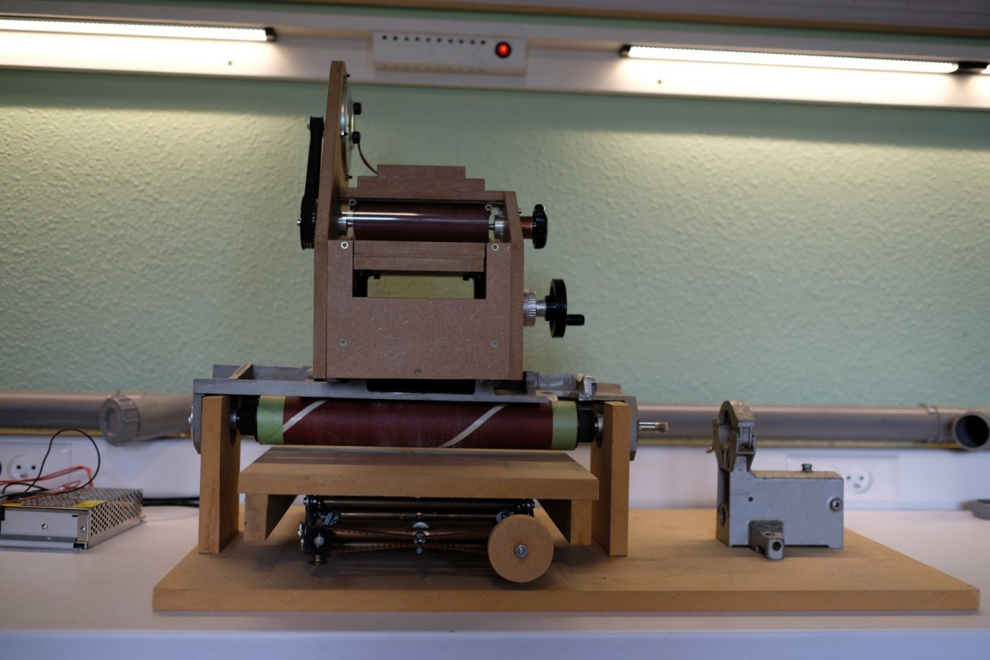
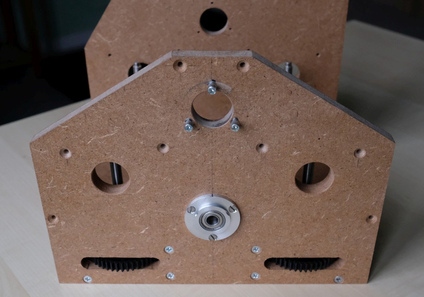
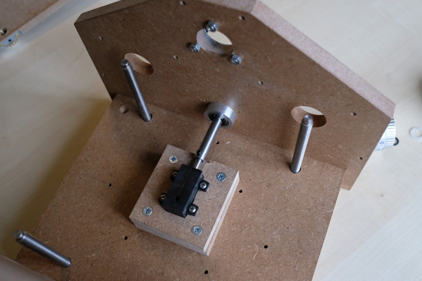
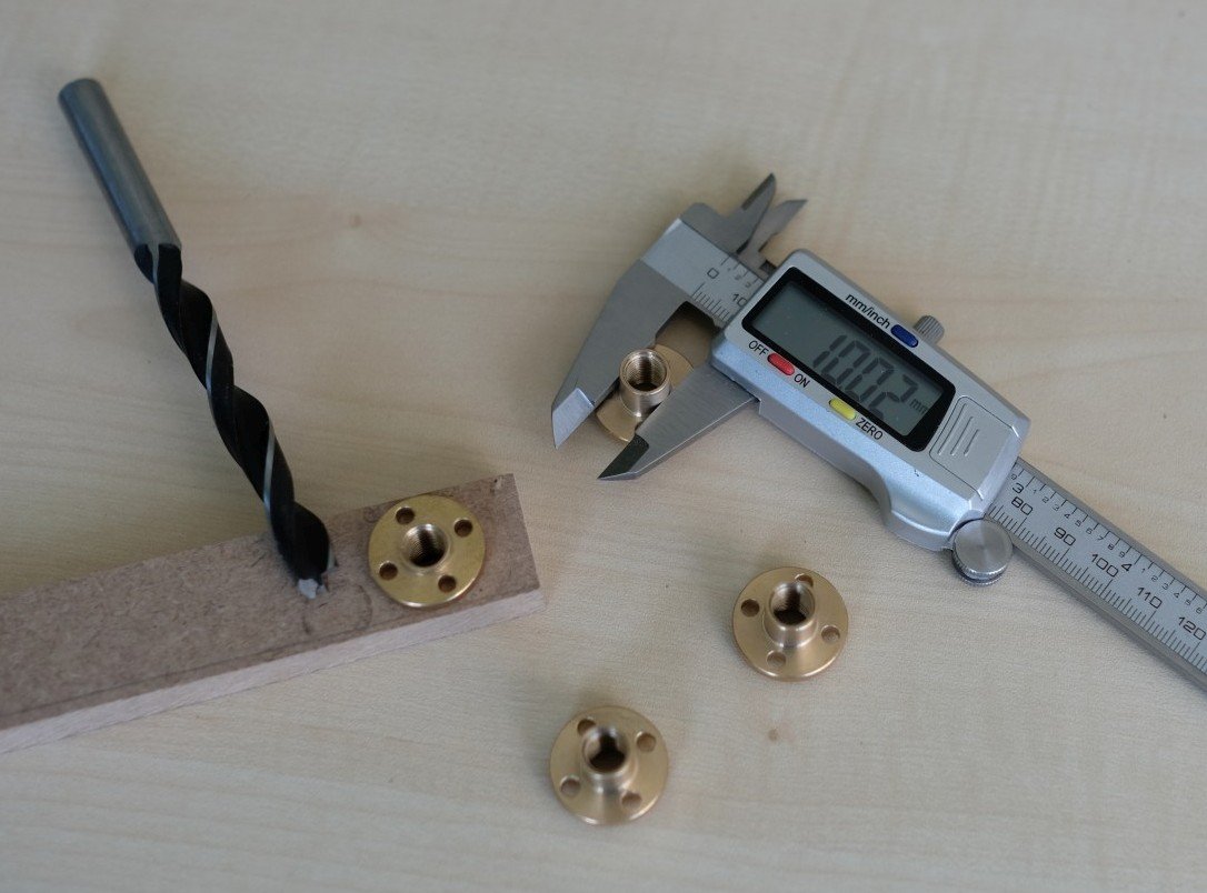
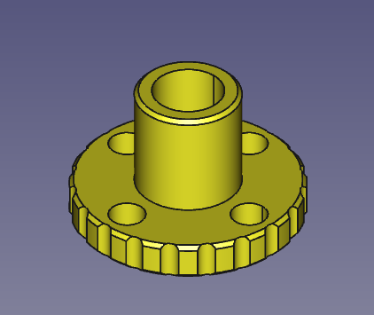
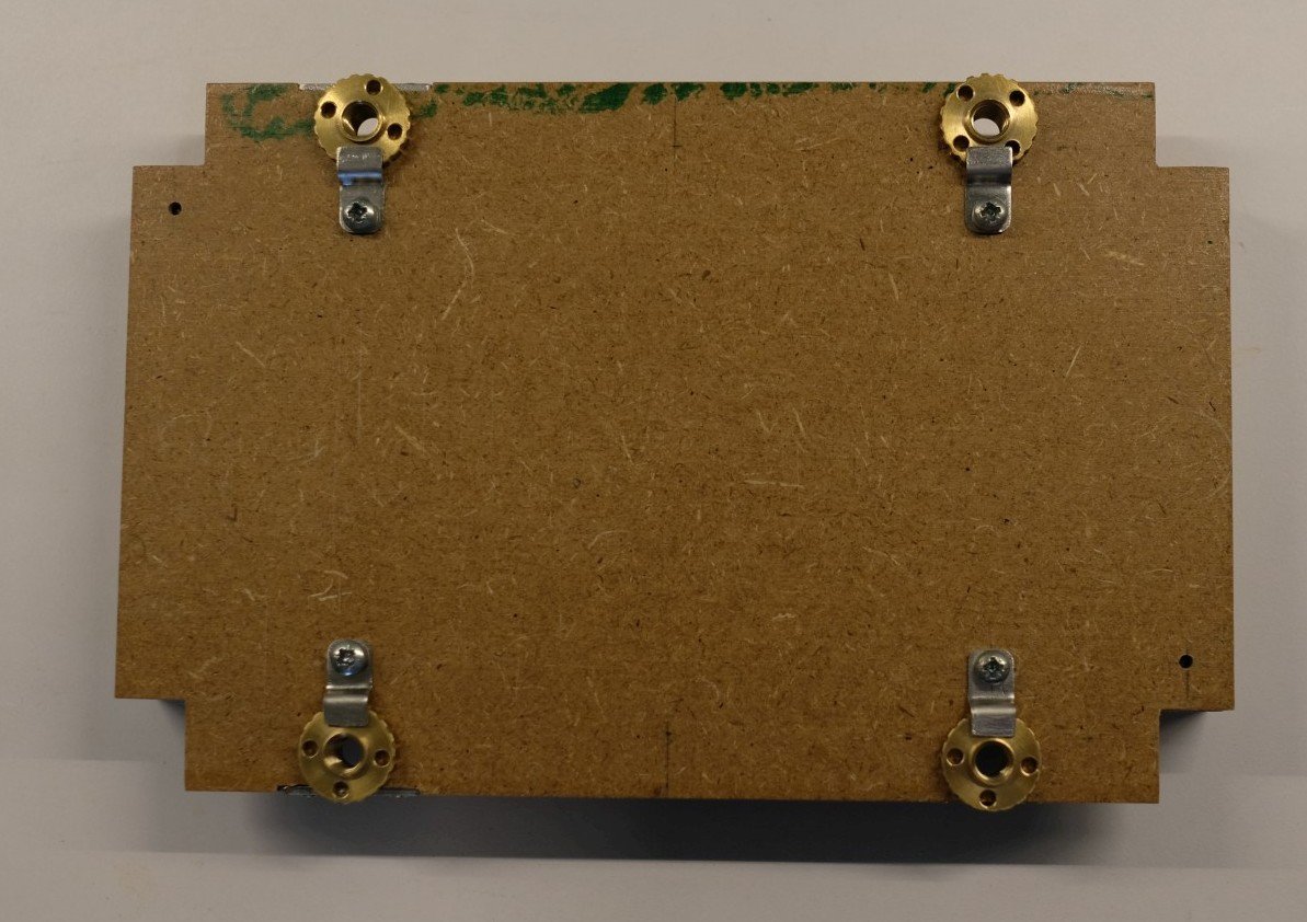
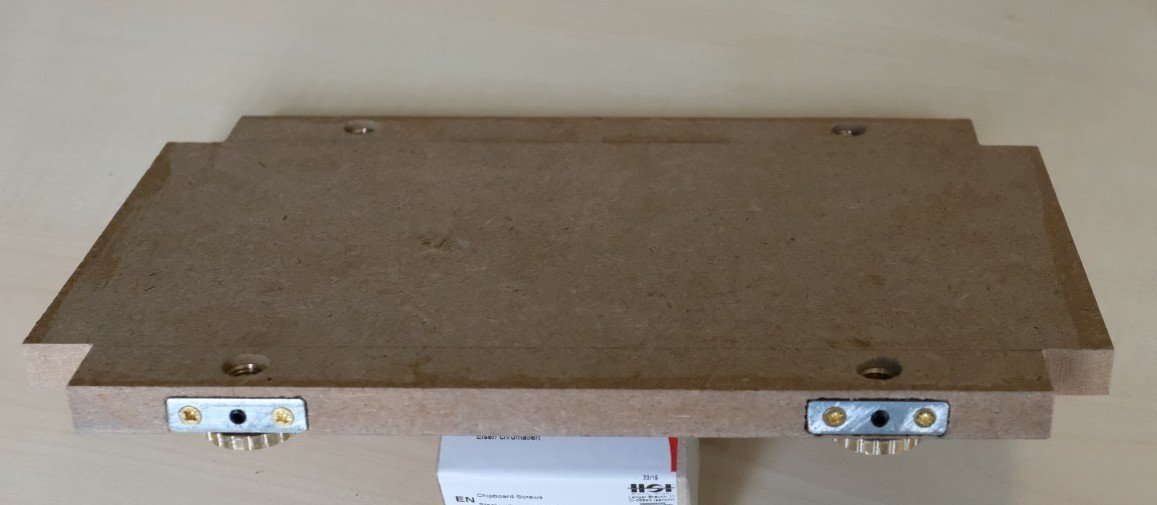
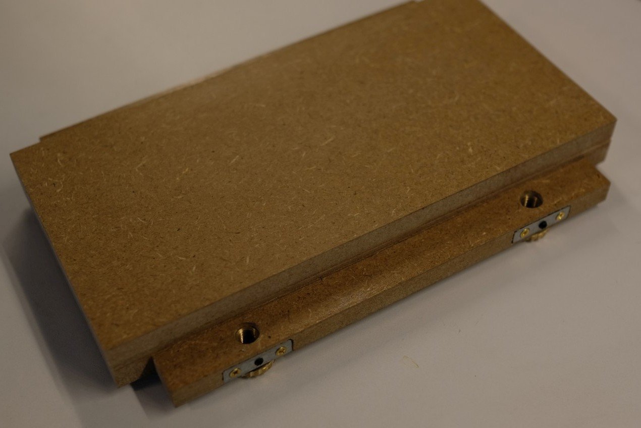
Now let’s go for the last mile of this thickness sander. The drum or roller is massive beech and has only 2 centred holes of 6 mm at its ends. So it must be supported from both sides by a 6 mm steel axle. I mount these 2 axles with a flanged bushing in the MDF side plates. The 2 holes (26 mm diameter) for the bushings are drilled in one go on the drill stand with the side plates aligned. Each bushing holds 2 bearings so that there is almost no play on the 2 axles. The next picture shows the side where the drive of the drum is done, shown from out- and inside. The other side has just a free running axles, shown next from in- and outside. I changed the flange such that I can easily take it out without needing tools. It comes in handy when you want to change the sanding drum. Now that the drums can be driven, I took some time to sand the wooden drums so that they are parallel to the height table and have almost no eccentricity. A thin flat metal plate with some sanding paper mounted with double coated tape was used. Patience and regular checks of the eccentricity with the motor turned at low speed resulted in a nice set of sanding drums. A dust extraction is the only thing yet to add. It is made with 3 pieces of MDF that will cover the top of the sanding drum. The sides are covered with segments cut from a plexiglass pipe (50 mm outer diameter, 3 mm thick). You can see that I use the 3 MDF pieces to transform the round hole into a slit that covers almost the total roller width. The plexiglass tube segments got small tabs crewed on to have some grip for placing or removing. The bottom of the large MDF piece has 2 grooves (2 mm deep) where it will meet the plexi segments. I added 4 small pieces of beech that are glued in these grooves and then got a round-up with a chisel. They should hold the plexi segments in place and provide some ‘click’ when mounting. Here the top part is mounted. And next is shown how the plexi segments are added. They just sit on tiny nylon tube parts sticking out about 3 mm from the side plates. Once supported the plexi segment is rotated up until it click’s against the MDF part. I almost forget to mention the drive of the DC motor. Its a 15V 10A power supply with a PMW (Pulse-Width Modulation) circuit added that feeds the motor. Now the thickness sander tool is ready for use. It is shown on my workbench with the dust extraction attached to the vacuum system. And to complete the circle I add a size comparison of old and new sander. This ends my story on the new DIY thickness sander. I hope that you enjoyed it and maybe it can inspire you for some more tooling projects. Best regards, Kris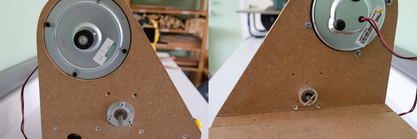
-
A DIY thickness sander
Kris Avonts replied to Kris Avonts's topic in Modeling tools and Workshop Equipment
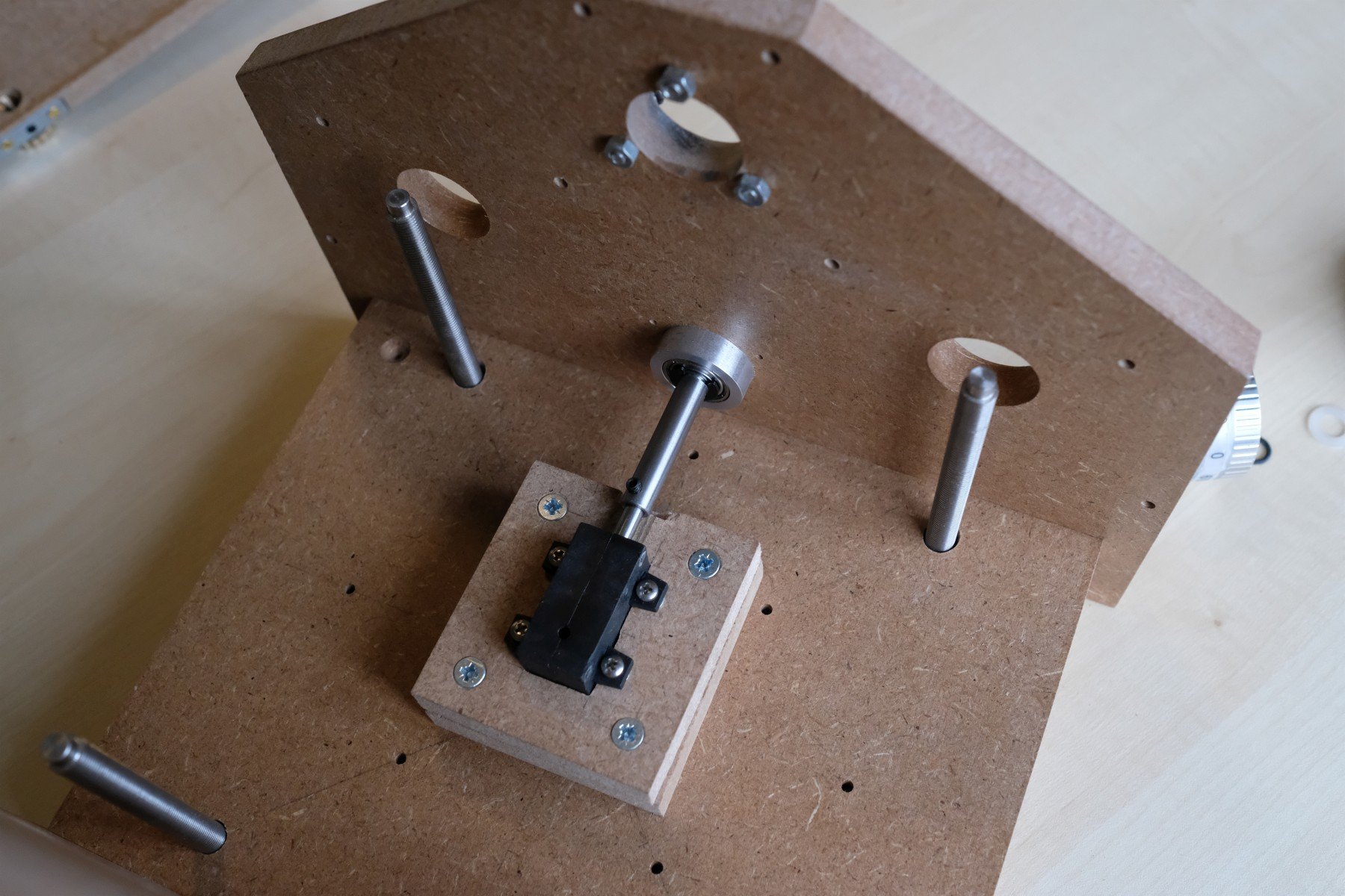
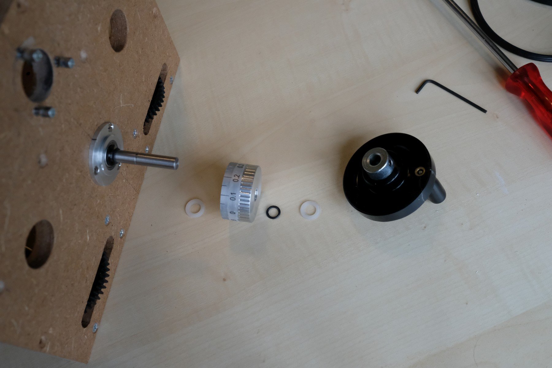
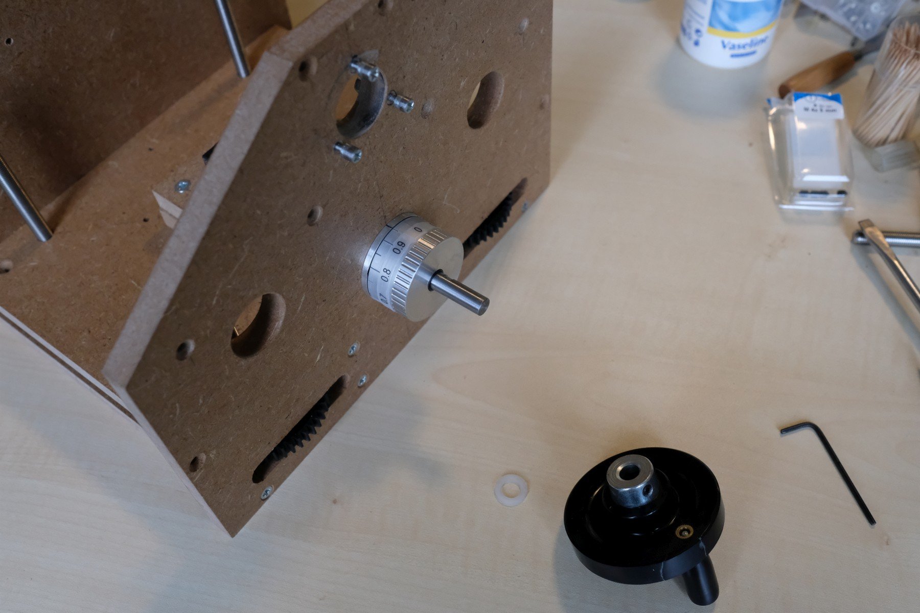
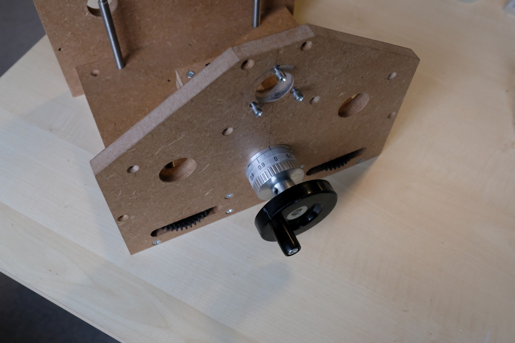
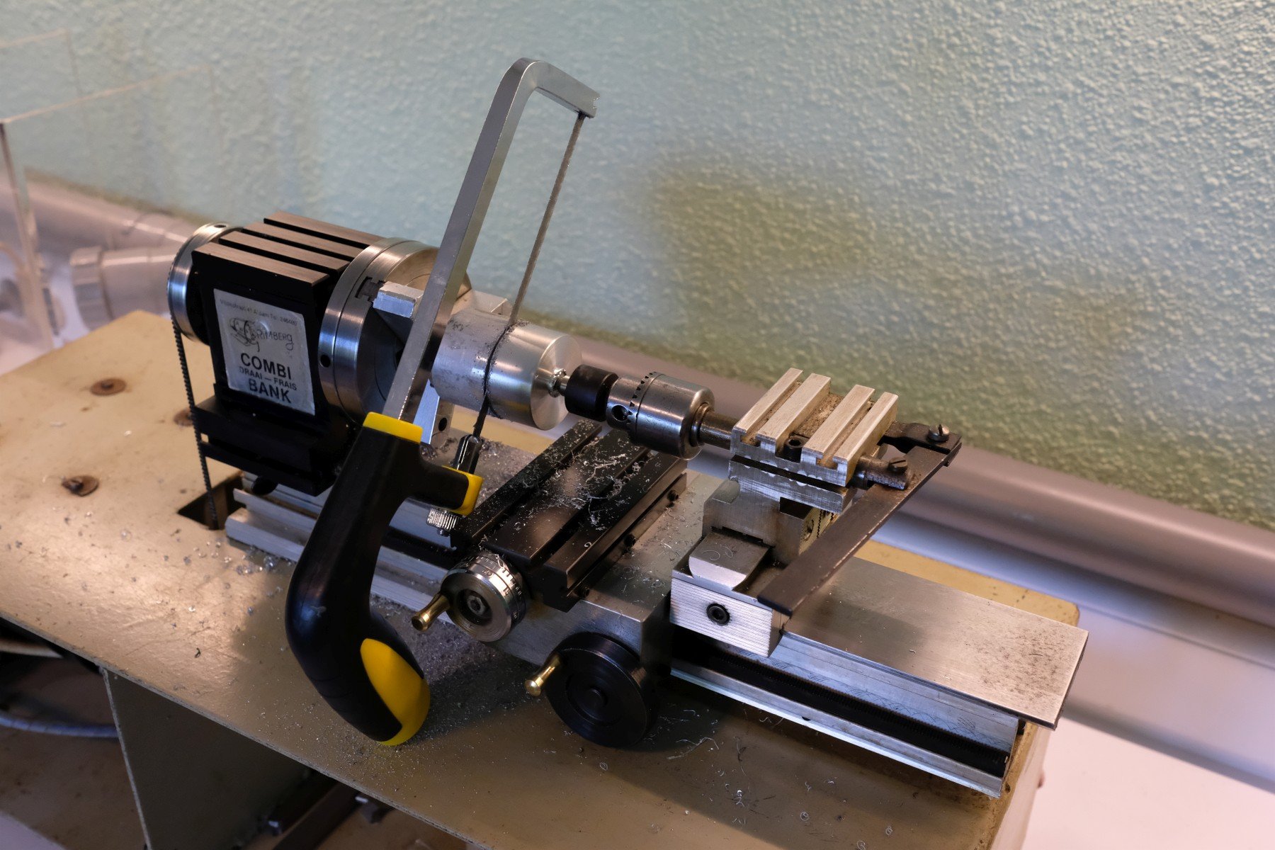
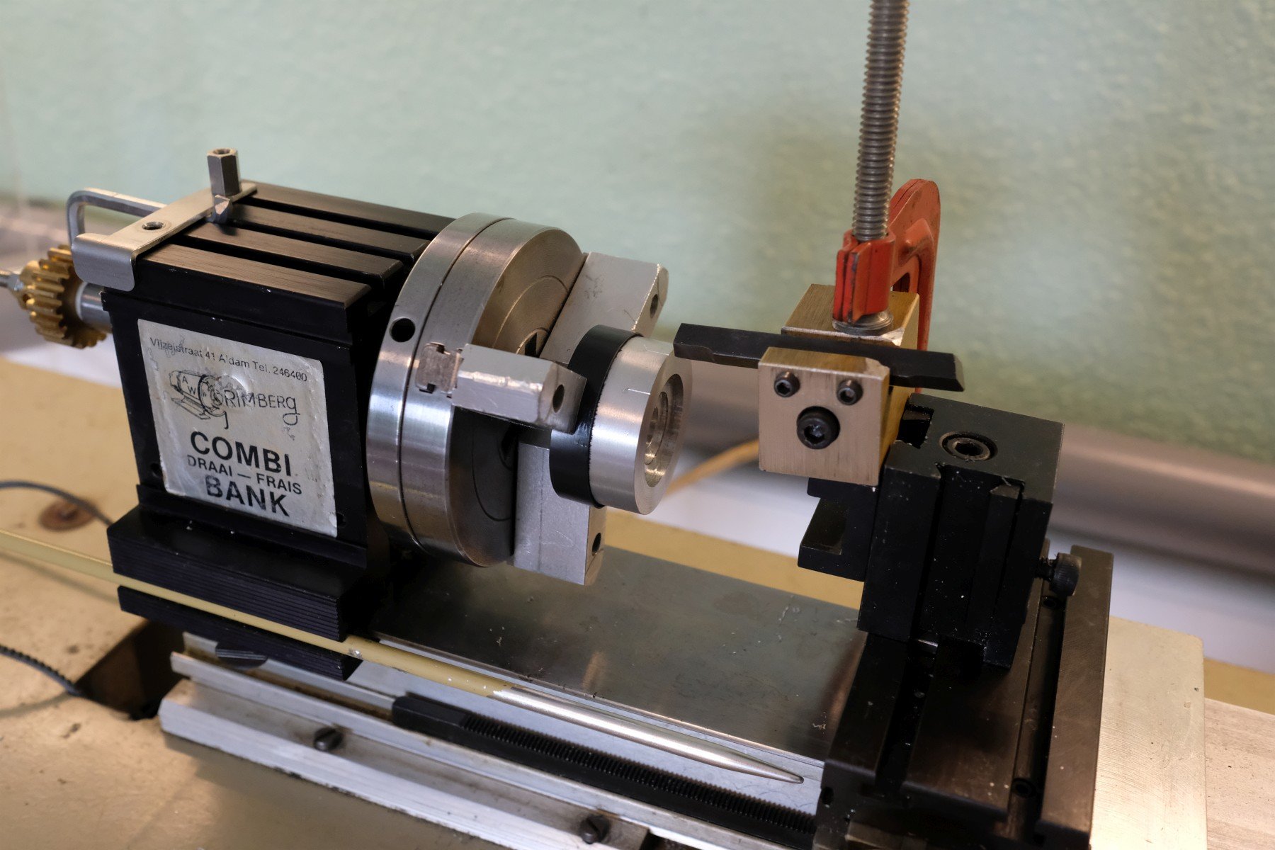
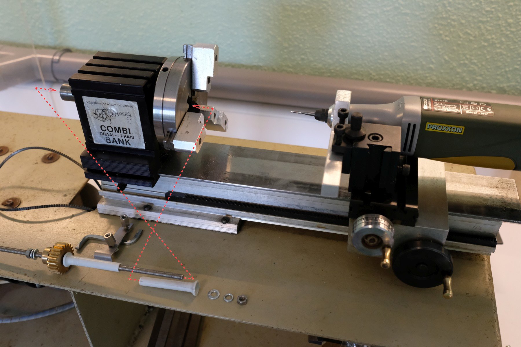
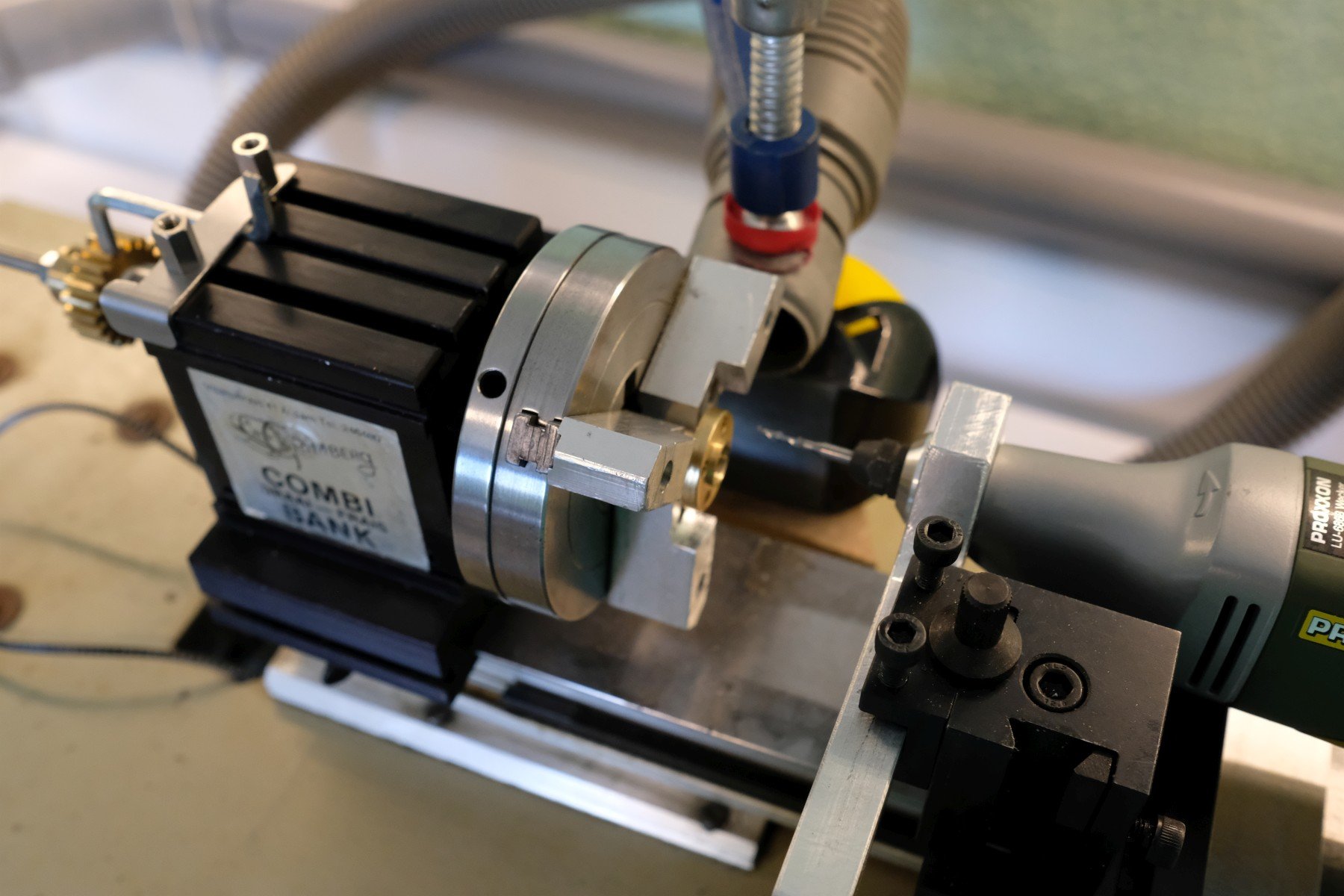
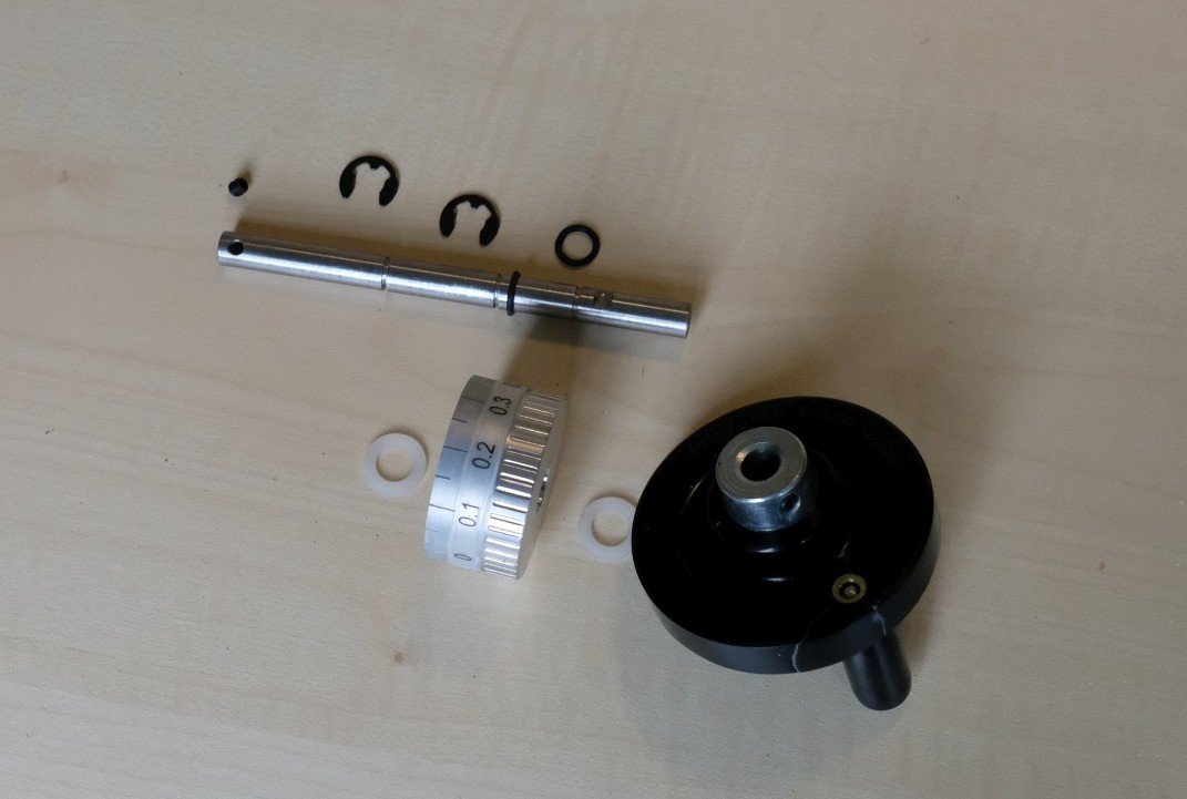
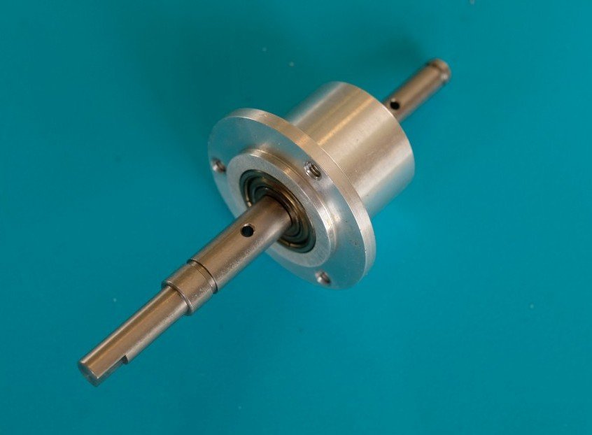
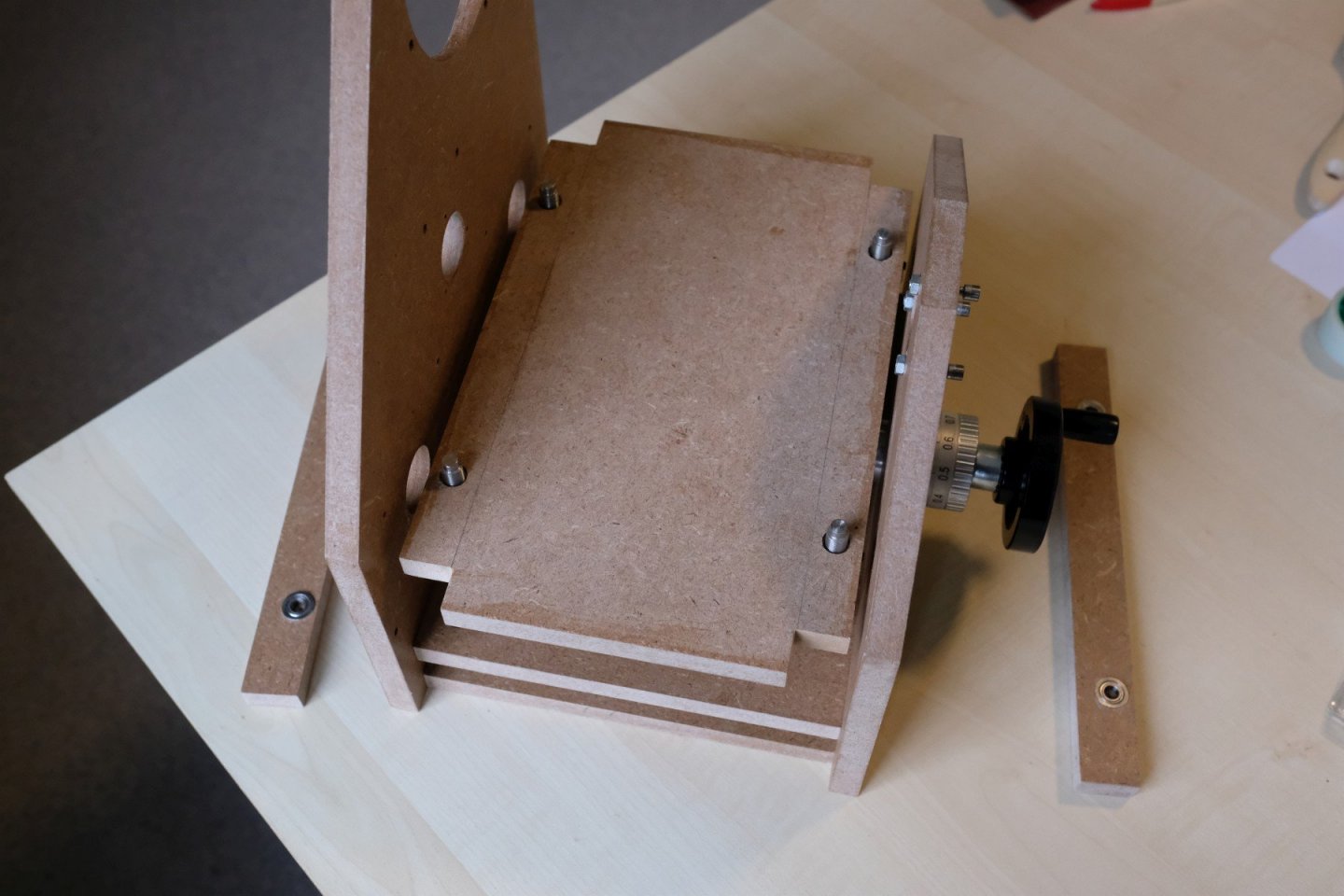
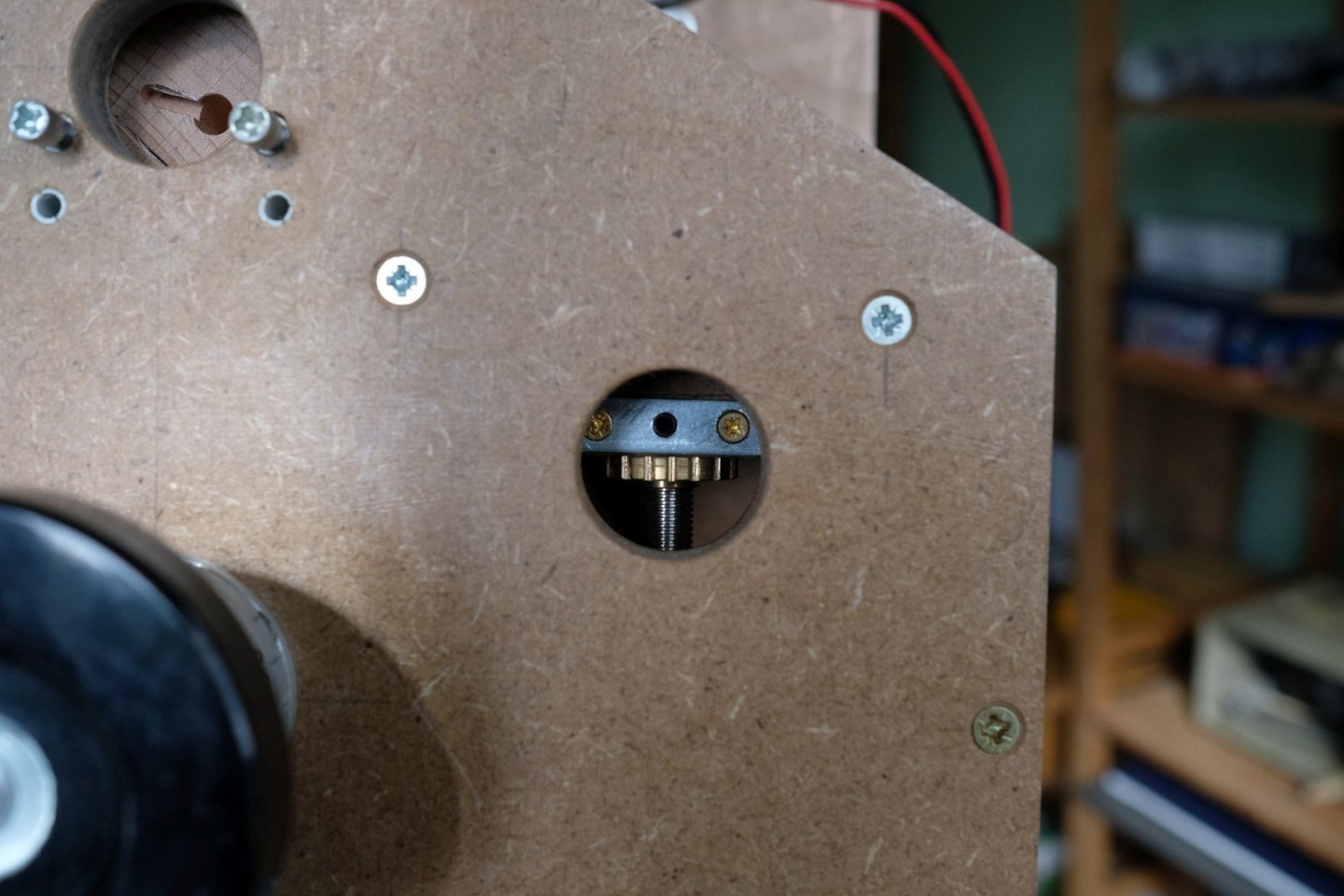
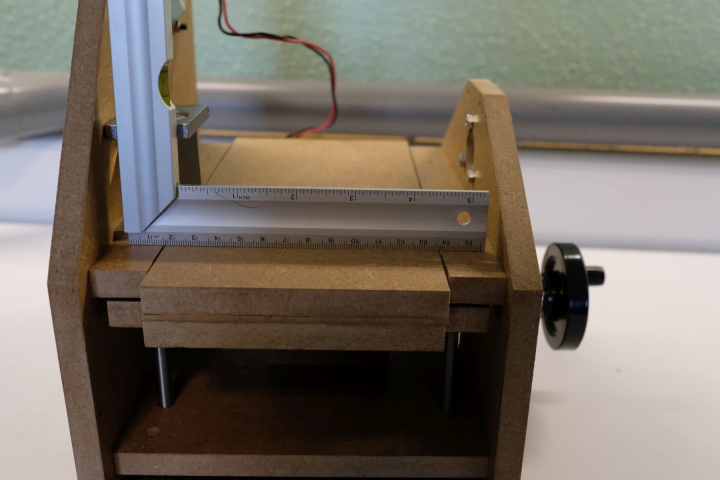
On we go with finishing the height control in this part. The bevel gearbox I used was bought at Conrad and they have the next data sheet on their website. datablad-222355-mfa.pdf As you can see in the picture it has some annoying bolts and nuts that stick out from its body. I remedied that by drilling counterbored holes at both sides of its body. The screw heads just fit in and the nuts are melted in with a soldering iron. After mounting all bolts again, the sticking out parts are ground off. Then it was easy to mount it on top of the gearbox with 2 pieces of MDF (see last picture in the previous part). The axis is now horizontal but has to be lengthened to bring it to the outside of the tool. The next picture shows all the parts to do that. The steel rod is 8 mm in diameter and will be supported by 2 bearings sitting in a flanged bushing, shown next (different axis in this image). I have several of these and I will also use them to hold and drive the sanding drum. I only need a 26 mm diameter hole in the MDF side plate. Next it is shown already mounted. Then mounting all the pieces can start. First the connection with the outgoing axis of the bevel gearbox is made. Then an axle lock is placed (not yet present in the next picture). Then we continue from the outside again with an axle lock, a nylon washer, a rubber O-ring, the self-made dial and a 2nd O-ring. And we finish with a nylon washer and a 60 mm diameter handwheel. Done! Then it is time to add the height table and verify how turning the whole construction feels. In the above picture the bearings on top of the spindles have yet to be mounted. Once that was done the table can be moved up and down with the handwheel. To be honest, you cannot turn it with just 1 finger, but with some firmer grip it is OK. I use the handle only for large movements of the table, smaller advancements are done with grip on the wheel. With the table in its upper position you can reach the nuts that support the table through the some extra 26 mm diameter holes in the side plates. Now the table can be levelled. With a straight metal piece as reference (a square in my case) and some light from behind, that was easily done. Tightening the locking bolts finishes the height table construction. As some distraction I can also show how the dial was made (I hope ’dial’ this is the correct word to describe the ring with the scale on it). First some ½ hour sawing the aluminium base material. Then the same trick with the poor-man’s divider, this time with a gear having 45 teeth, and the proxxon drill to make grooves for better grip. Then turning the ring around in the lathe and making the scale (again using the gear with 20 teeth). Some improvisation was needed to mount the chisel. A simple tool holder with very sharp chisel mounted on another one that has height adjustment and a 2.5 mm diameter drill between the 2 to get some slant. The scale is printed (in reverse) on a transparency sheet and wrapped around the ring. It is fixed to the ring with some tape over it. That’s it for today, see you next time to finish with the sanding drum mounting and adding the dust extraction. Best regards Kris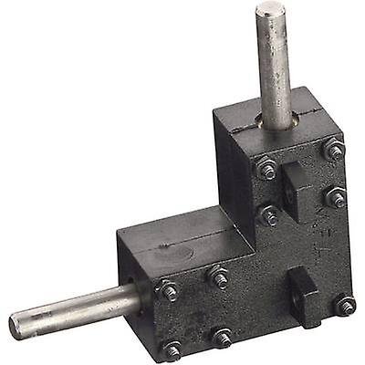


-
A DIY thickness sander
Kris Avonts replied to Kris Avonts's topic in Modeling tools and Workshop Equipment
Hello Bob, Yes I can access that article. It's of a more classic design but well adapted to the lathe. Certainly enough power to sand wider pieces of material. The popular mechanics article, I also discovered that some time ago. It is still inspiring for its straightforward and simple construction. thanks, Kris -
A DIY thickness sander
Kris Avonts replied to Kris Avonts's topic in Modeling tools and Workshop Equipment
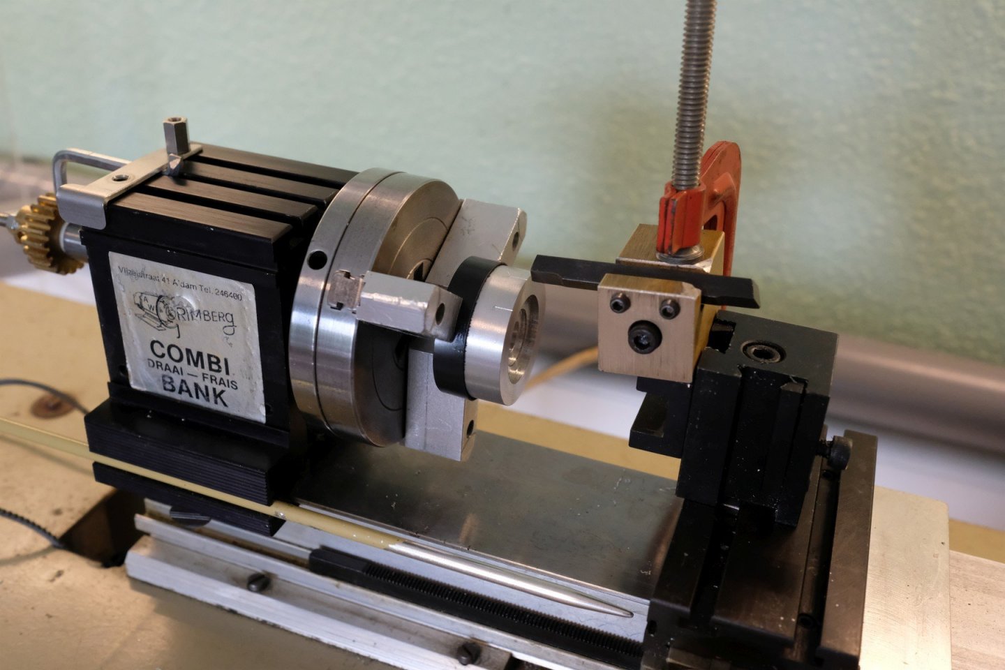
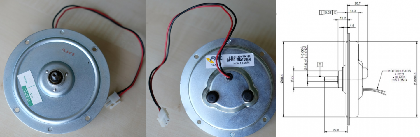
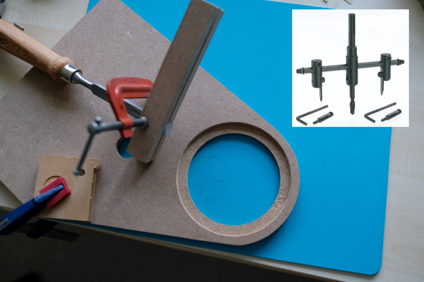
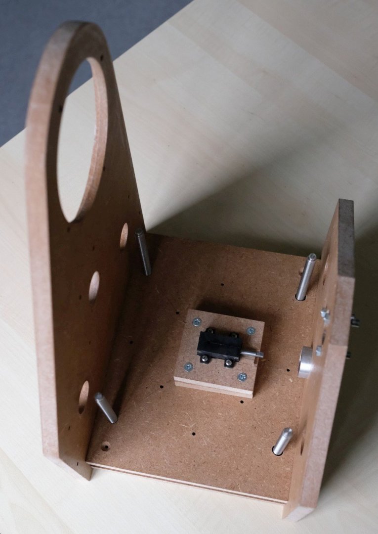
Hi Jaager, the 4 degrees of freedom actually reduce into just 1 degree of freedom by the gearbox construction. That will be shown more clearly later. Let’s go on because it still doesn’t look like its going to be a thickness sander. Adding the side plates (also in 12 mm MDF) will help to imagine what the final tool will look like. Here is a model that shows both side plates. The plates are asymmetric because I wanted to integrate the motor in the left plate. The motor is a brushed DC motor of the ‘pancake’ type. It is shown next. While small it is quite powerful when run at full speed. To mount it a large hole was made and then a recess to accept the flange and bring the motor pulley to the plane where the larger drum pulley will come. The hole and the recess are made with an adjustable circle hole cutter and then the recess was cleaned up with a chisel clamped in some support to get the correct depth. Then it was time for a test drive. Now we switch to the height table. That is also a 12 mm MDF plate that will sit on the 4 spindle nuts. Because The part of the nut that fits into holes of the MDF plate has 10.2 mm diameter and since I have only a 10 mm drill, the nut was turned down to 10 mm on the lathe. A piece of scrap MDF was used to judge the fit: firm but possible to rotate as is required for levelling the height table. To get more grip on these nuts for adjusting, I made some profile on the outer edge. That was done on the lathe with the main spindle turned into a simple self-made divider and my proxxon drill with 3 mm mill mounted in the tool holder. The parts to make the setup are shown next. The tread is M5, the gray parts are cut from hammer nail plugs, the gear has 20 teeth and the hex key is an ‘Ikea’ key ground down at the end to fit in the teeth and in the middle to fit into the groove on top of the lathe main spindle block. All pieces mounted and in use is shown in the next picture. The height table seen from the bottom side. You can see that I added a small clamp to each nut to prevent any movement in Z-direction. And an image from the side where you can see small metal plates worked in that have a fixing screw in the middle for securing the adjustments made when levelling the table. As a last addition we have to thicken the height table so that we can use it for a sanding thickness range that goes to 0 mm. A 3mm spacer plate (hardboard) was glued on the height base plate and then an extra 12 mm MDF plate was added and held in position with 2 metal pins of 3 mm diameter. This extra plate can always be removed if you want to sand very thick pieces. Now we can move on with the construction. The gearbox with its top plate mounted is attached between the 2 side plates. You can also see a miniature bevel gearbox (90°, 1:1), the black part, that sits on top of the gearbox and brings the height control to the side of the tool. Details about that construction come in a next part. Best regards, Kris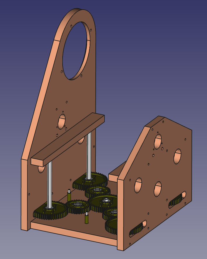


-
A DIY thickness sander
Kris Avonts replied to Kris Avonts's topic in Modeling tools and Workshop Equipment
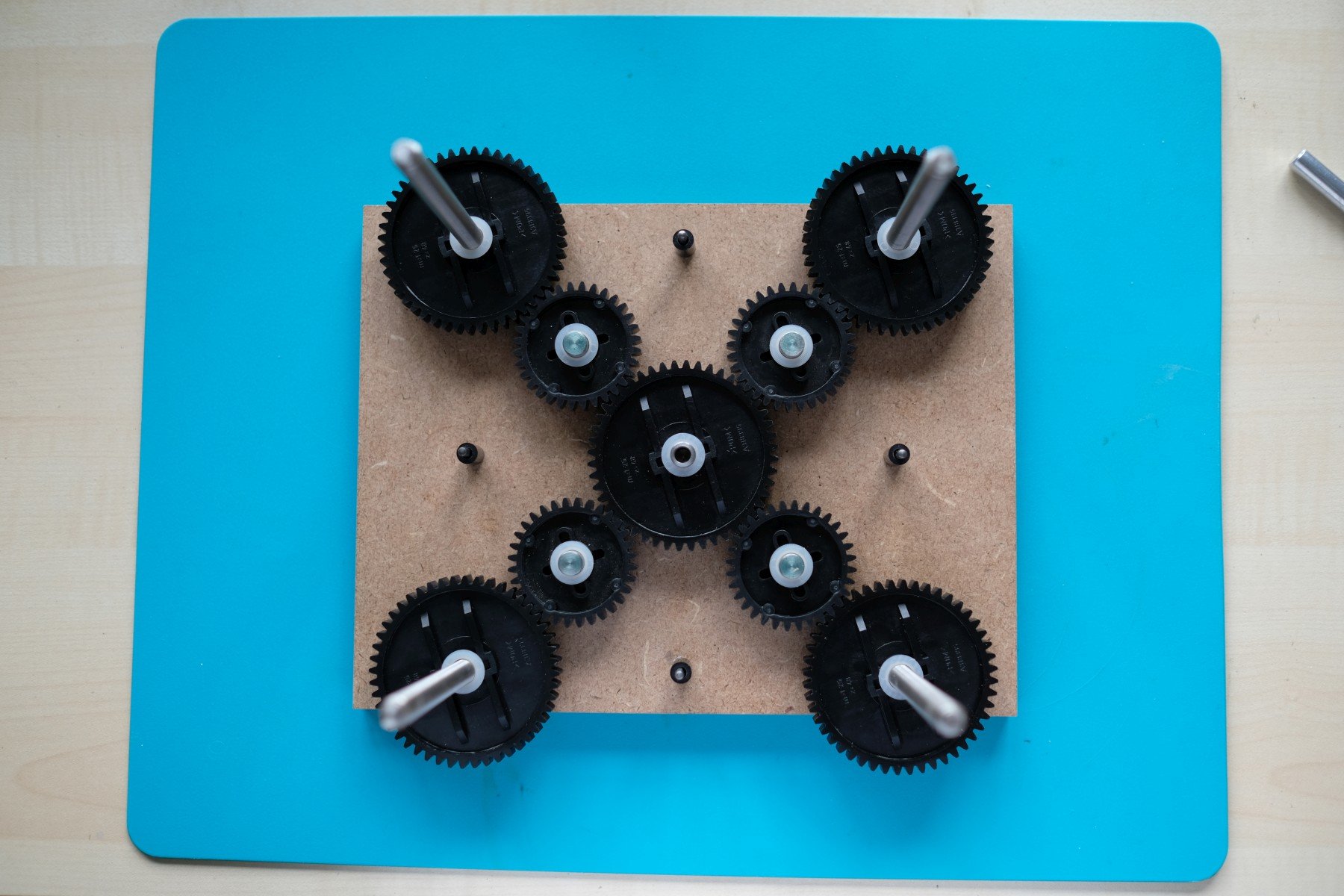
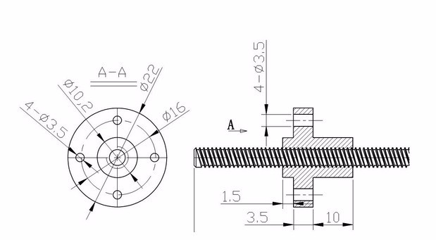
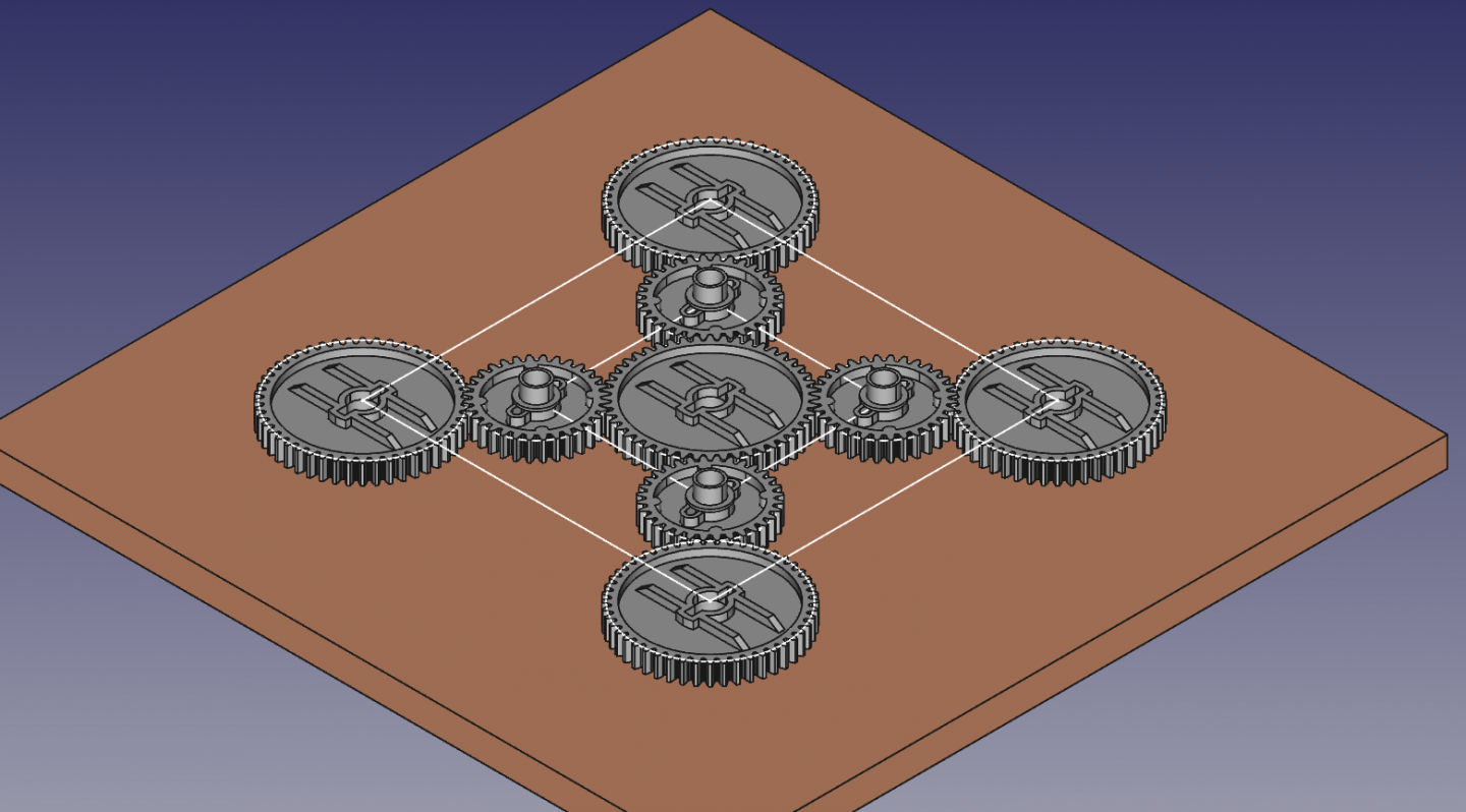
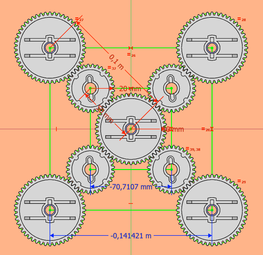
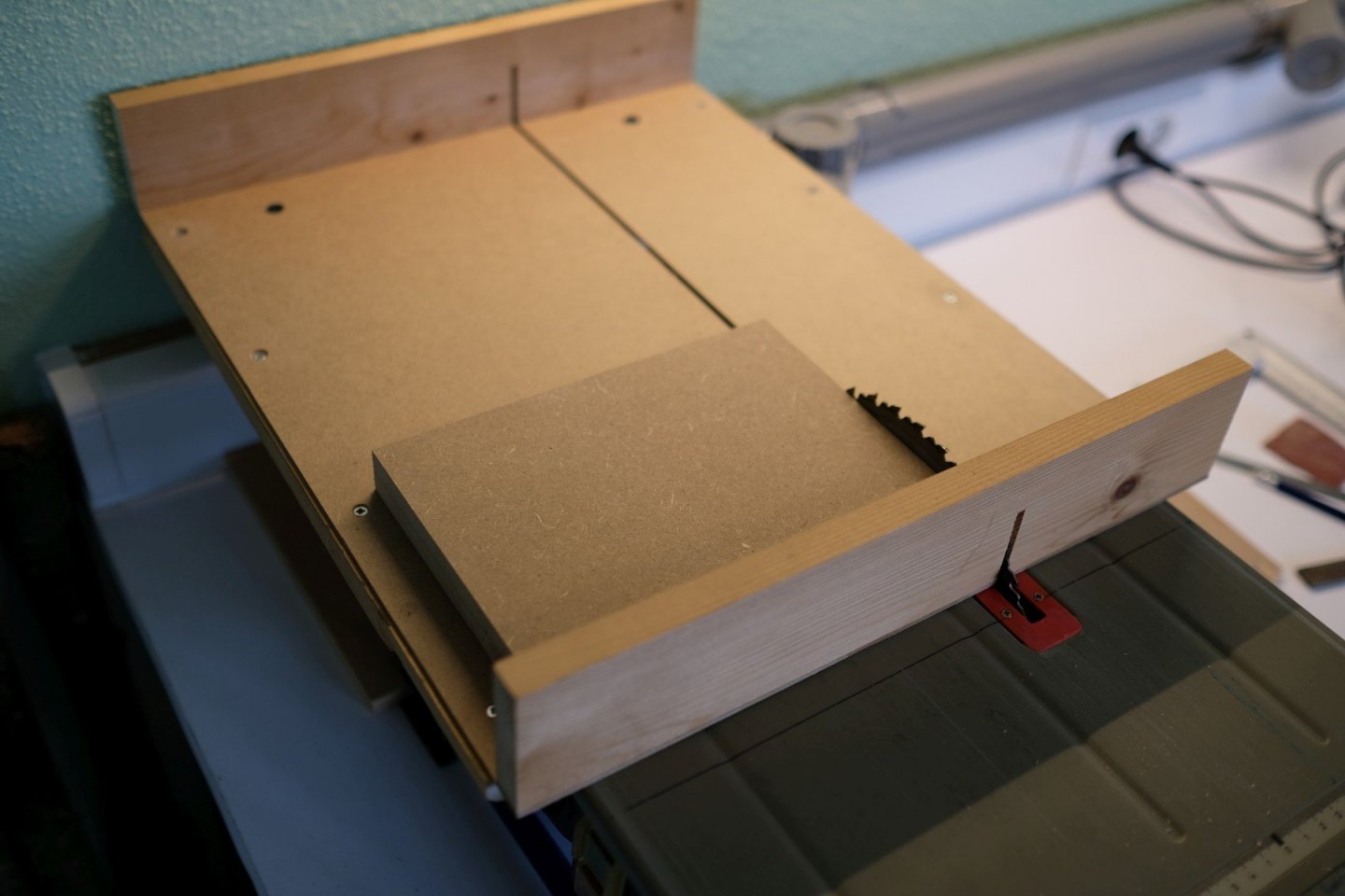
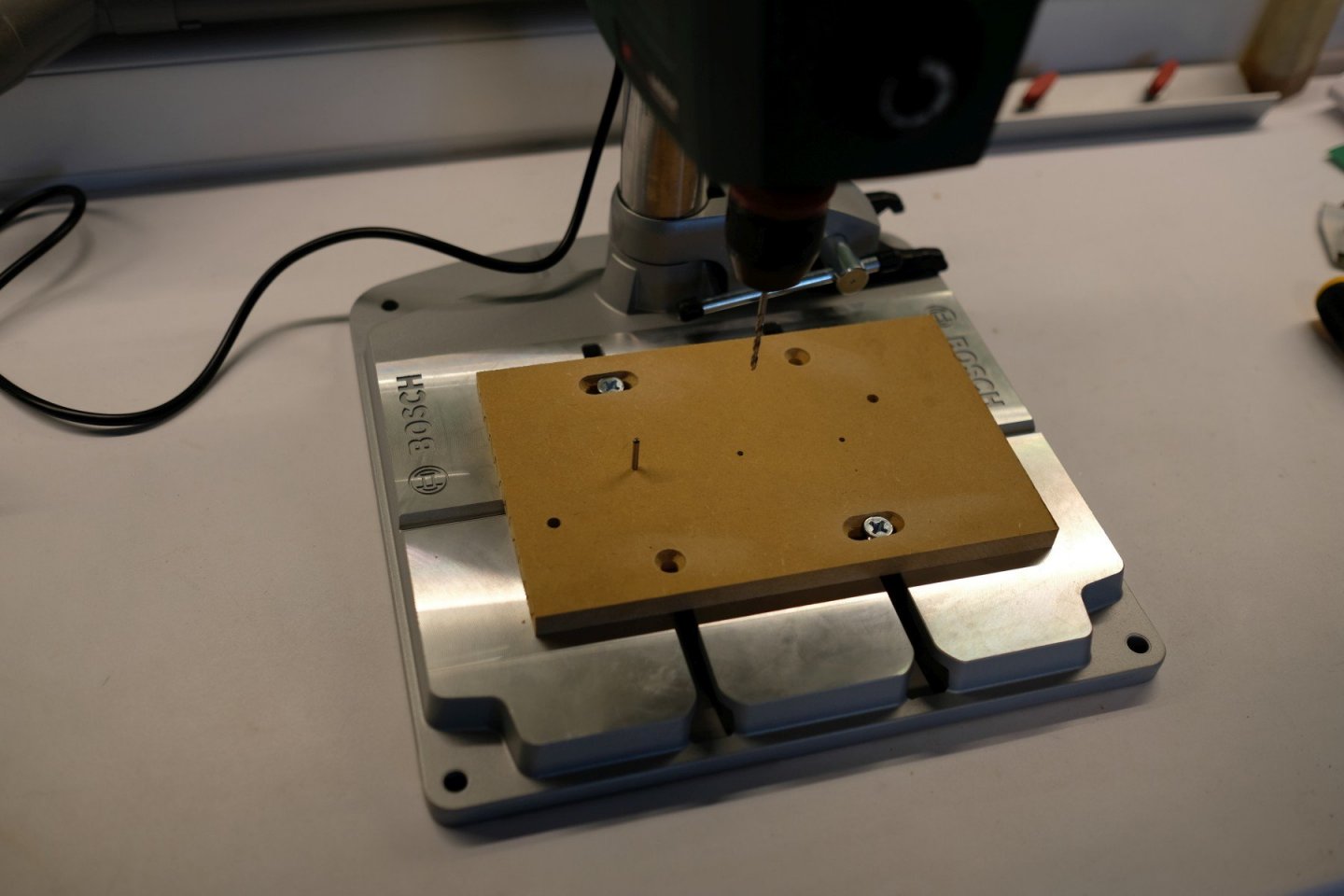
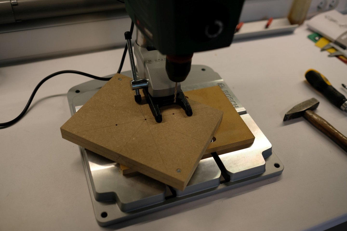
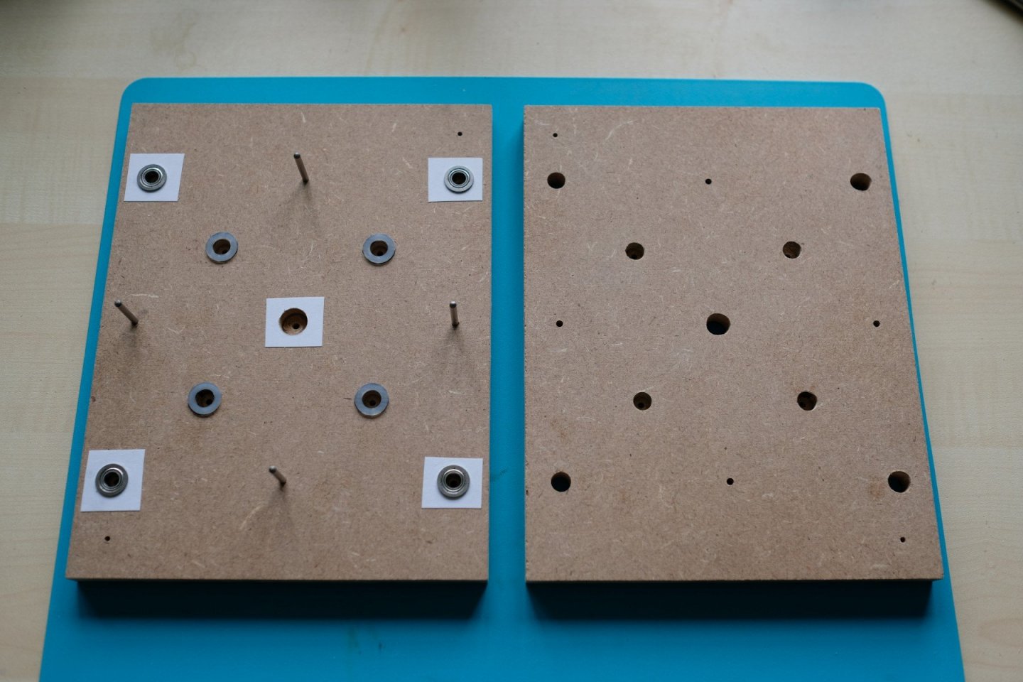
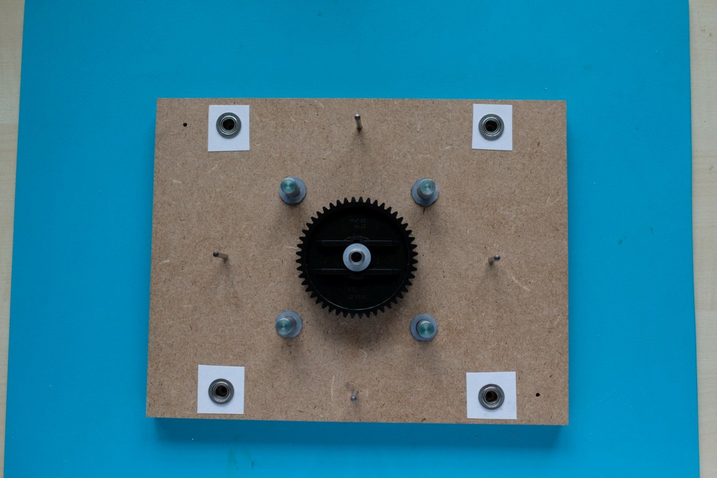
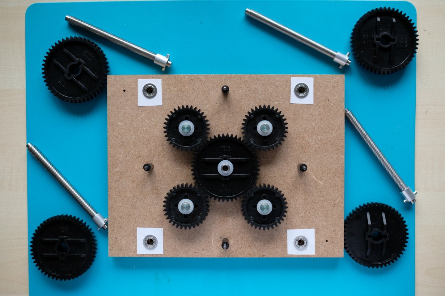
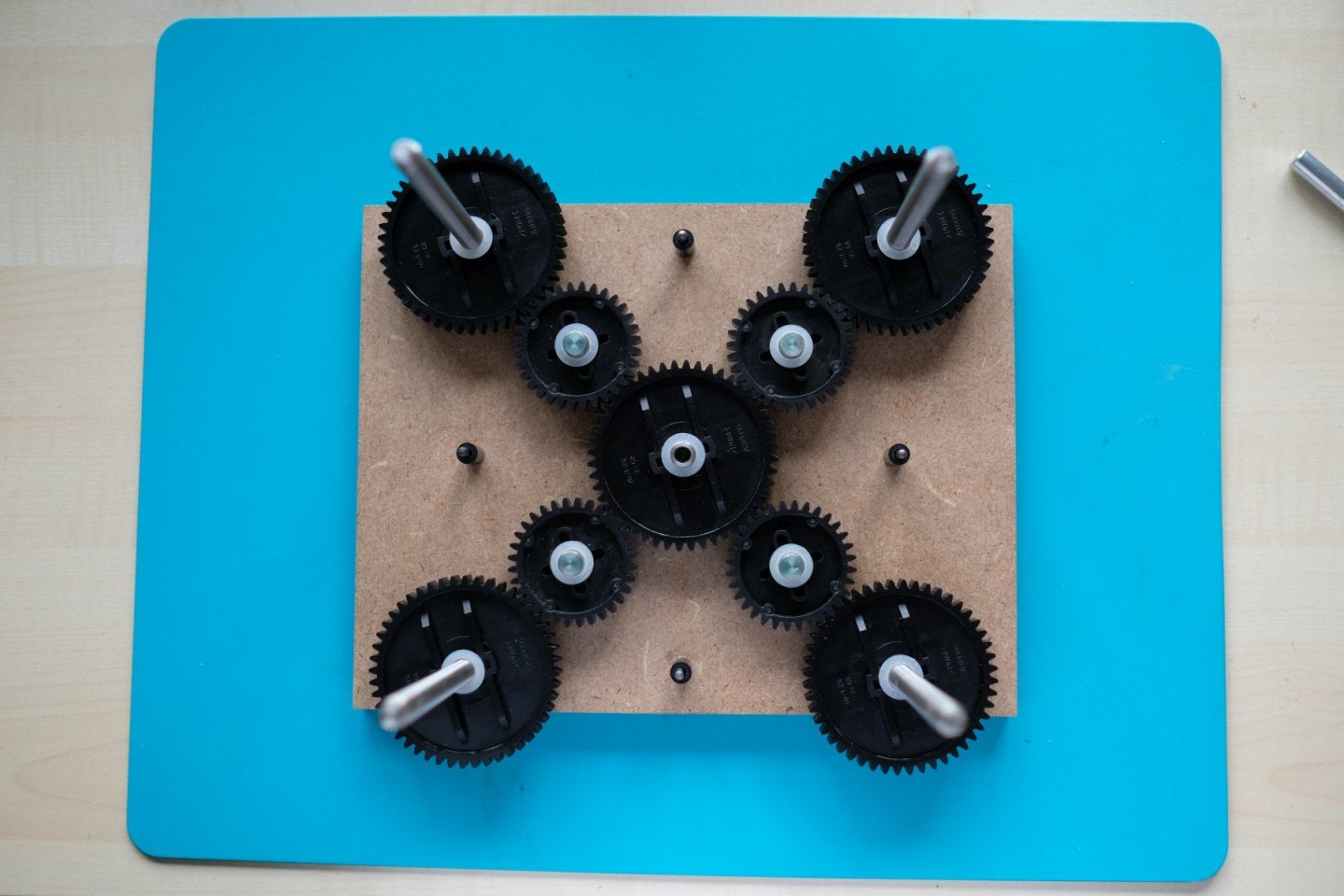
Jaager, this is going to be a 'mini' sander. But I will take care with the wood flour and provide an adequate dust extraction solution. In this part I will show how the basic construction is made. The idea is to have the height table mounted on 4 spindles. Turning the spindles will move the table up or down. This can only work if all 4 spindles have synchronized movement and depend on just 1 height control. As spindles I chose to use a lead screw type known as TR8x1. This has trapezoidal thread with 1 mm pitch. I ordered 4 screw/nut combinations of 200 mm in China (12.59 euro). The next picture shows the spindles and some dimensional data. To have these 4 rotate simultaneously, I interconnect them with gears. So I make a kind of gearbox that will be sandwiched between 2 bottom plates of 12 mm thick MDF. The next picture shows a model of the gear configuration. All gears have 1.25 as module, the large one has 48 teeth and the small one has 32. So measured from centre to centre we have 0.5 * ((48 * 1.25) + (32 * 1.25)) = 50 mm. The next image shows all dimensions. The spindles stand 141 mm apart and that is enough width for my height table to move between them. The next series of pictures shows the build-up of the gearbox. To start we need 2 plates of MDF that are of exact same dimension (170 x 220 mm), so I saw them together on my little table saw. Then we need a lot of holes at very precise positions. I made a simple jig with 3 holes of 3 mm in line and at exactly 49.9 mm between centres. Why not the nominal distance of 50 mm? Well, I wanted to eliminate the play between the gears. It was not a total success because when you reduce the play, other artefacts like eccentricity will come into play more dominantly. The 2 MDF plates are fixed to one another with 2 screws in opposite corners. The the first hole was made in the middle. From then on I used a 3mm steel pin in the jig to position the plates at the correct centre distance for a next hole. I made 14 holes in total. Then the 2 plates are separated and 10 holes needed to be widened to a suitable dimension to fit a flanged bearing (12 mm) or a steel rod (8 mm). This was done by first mounting a 3 mm drill bit in the drill stand to bring the MDF plate into position, clamp it. The exchange the drill bit to the wanted diameter and drill the hole to exact depth or trough as needed. I must admit that the depth display of my Bosch PBD 40 proved to be very handy. Next you see both plates with already some flanged bearings mounted. Then the gears come into play. First the centre gear that will also be connected to the height control later. Then the four smaller satellite gears are placed. They use no bearings but I inserted a nylon washer between the MDF and the plastic (POM) of the gear to protect the MDF from wear. Then the 4 large gears that will drive the spindles will follow. The spindles are made to a length of exactly 110 mm on the lathe and then the ends are reduced to 6 mm diameter for 4 mm so they will fit into the flanged bearings. You can also see an aluminum ring to adapt the spindle diameter to the 10 mm hole in the gear. I glued in 2 pins that will fit in a groove of the gear to drive the spindle. That’s the gearbox. It is covered by the second MDF plate. You can also see 4x a 3 mm pin with a plastic spacer that will keep the 2 plates parallel and at a distance to give the rotation parts a little play. As it is shown here it all looks simple. Believe me, it required a lot of tuning on all parts to get this whole mechanic move smoothly. Enough for today, next time the side plates and the height table will be added. Best regards, Kris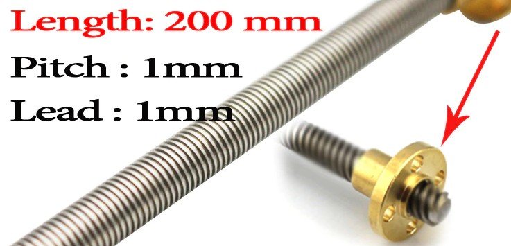
-
A DIY thickness sander
Kris Avonts replied to Kris Avonts's topic in Modeling tools and Workshop Equipment
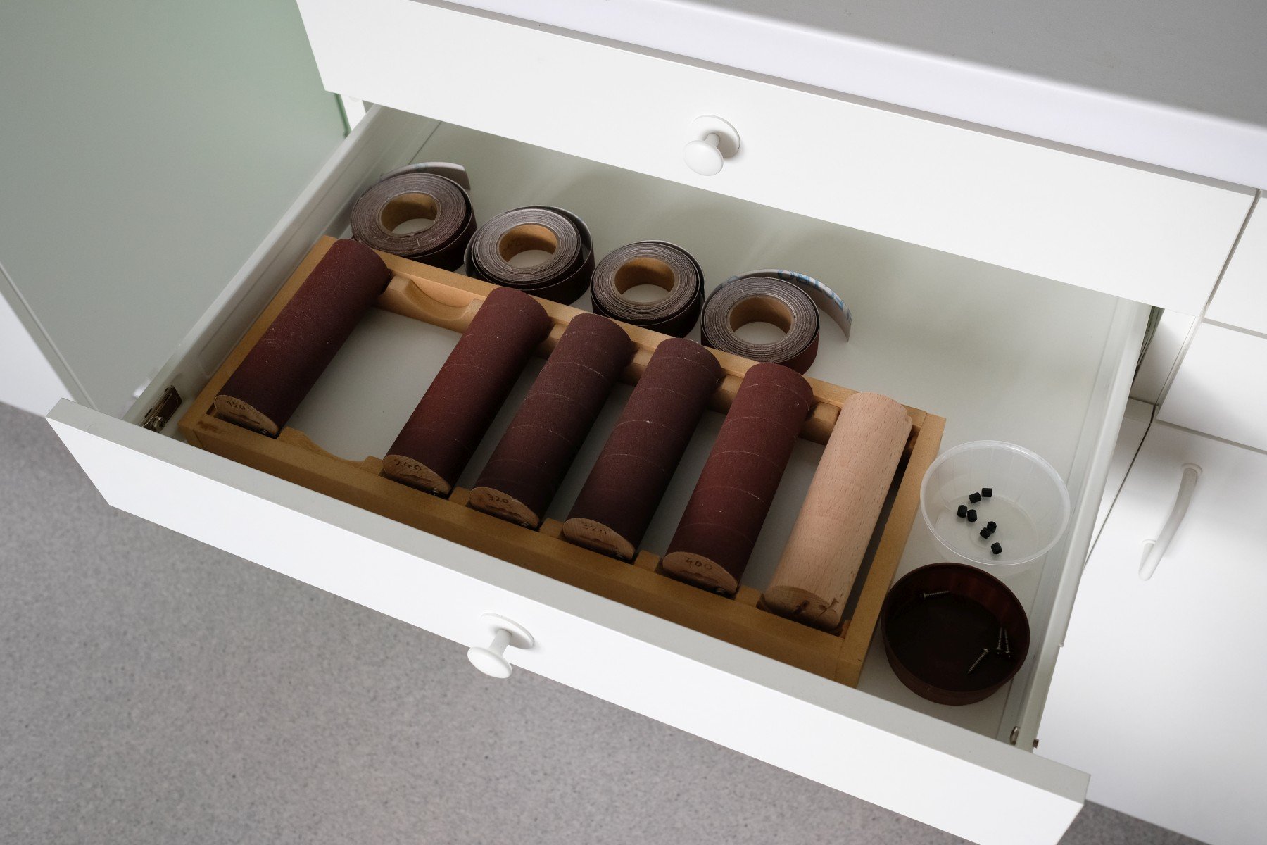
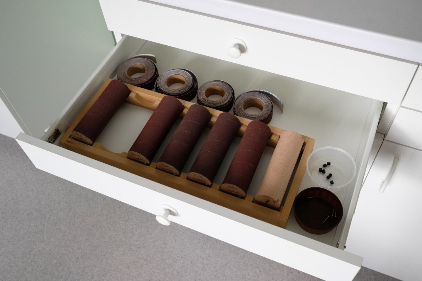
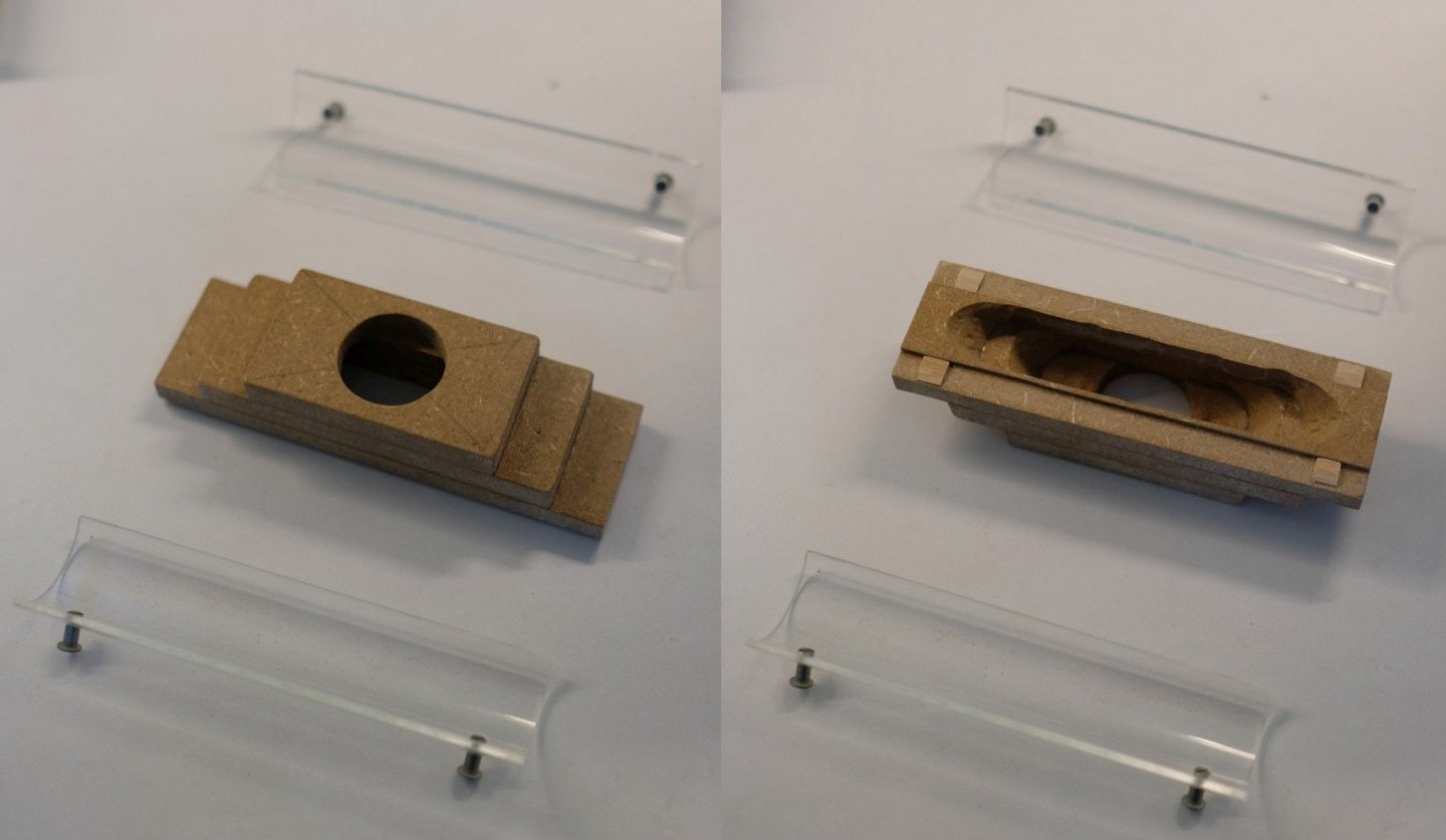
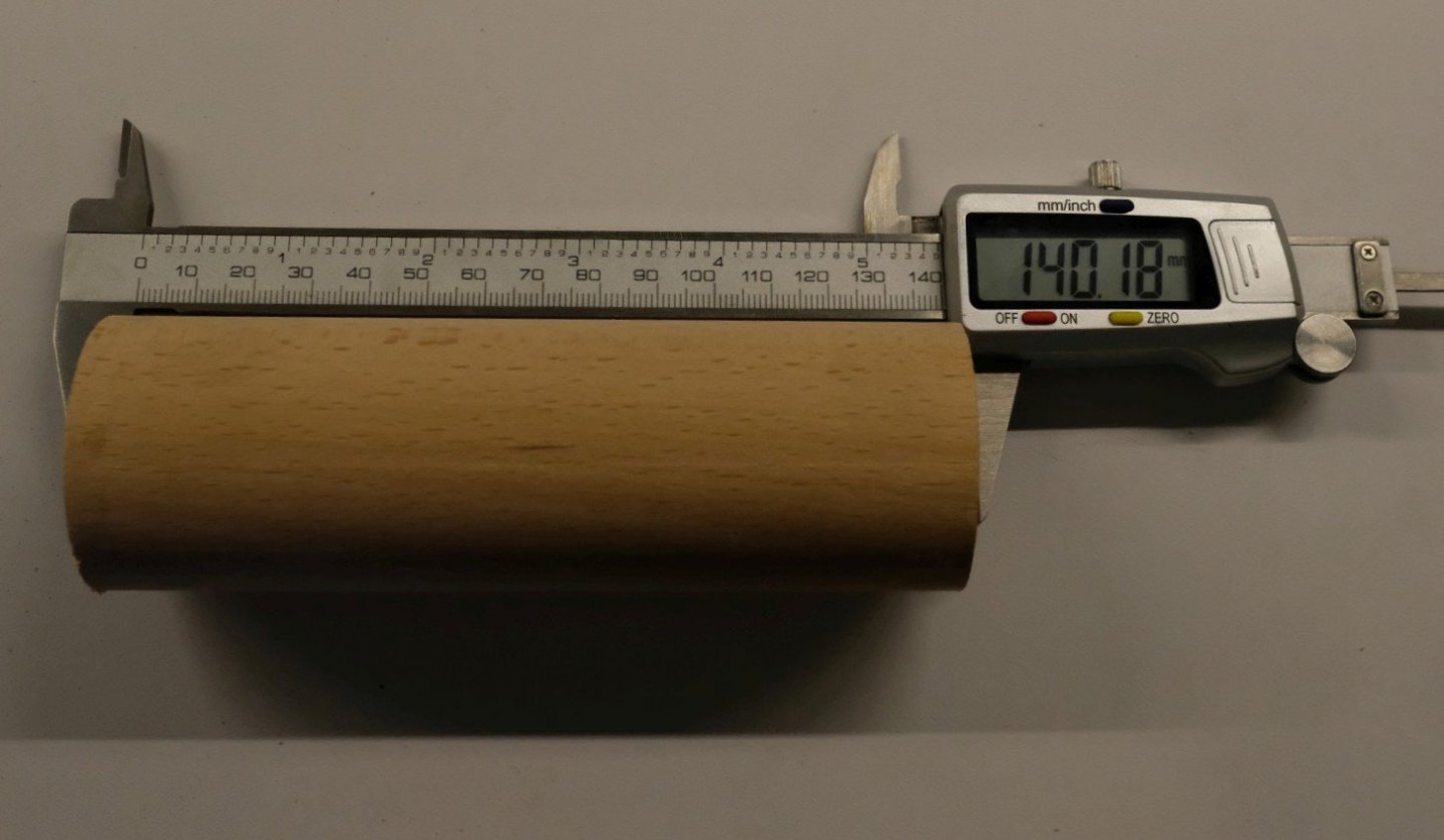
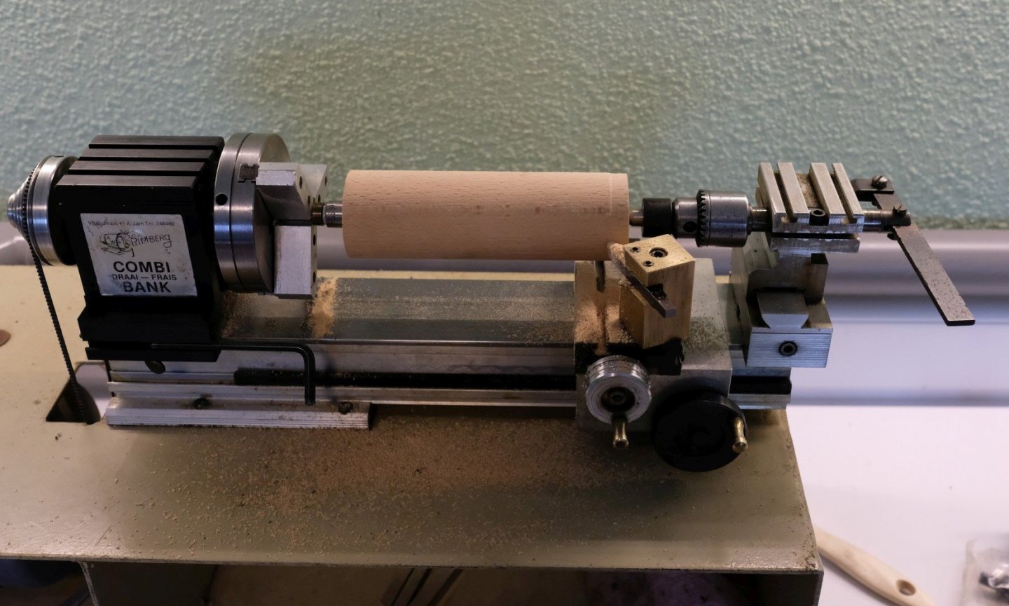
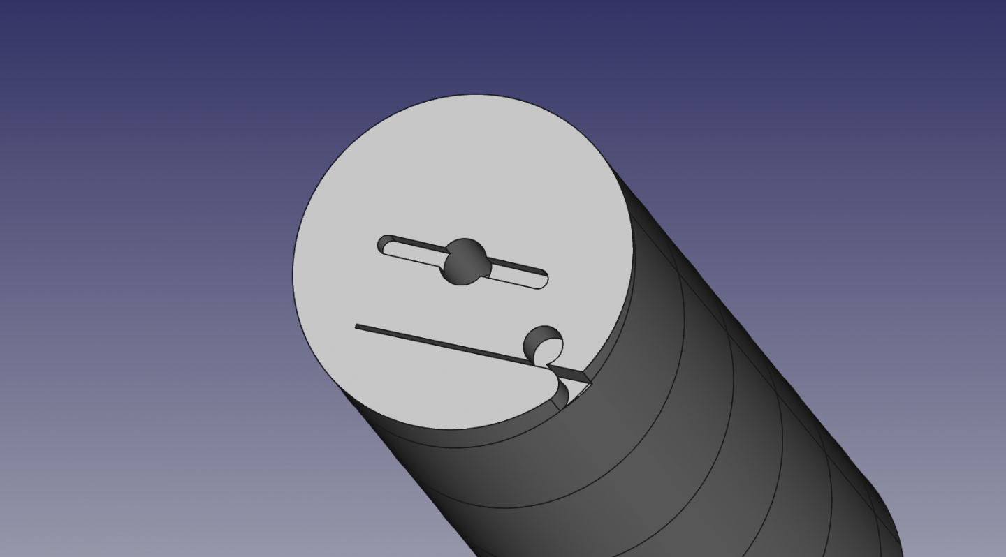
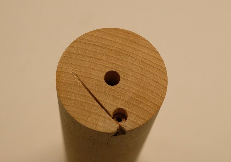
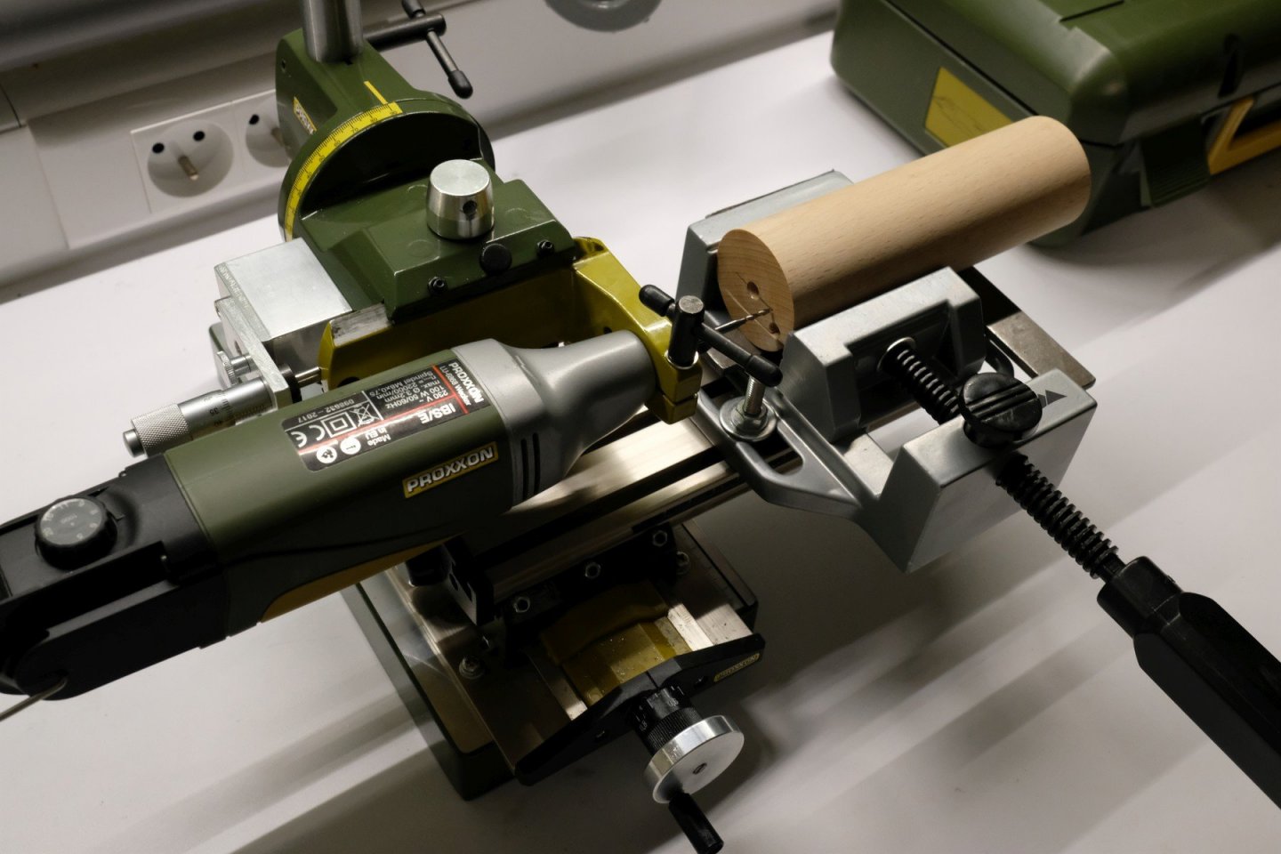
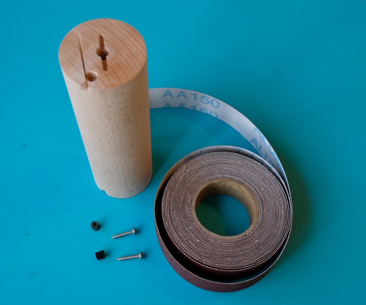
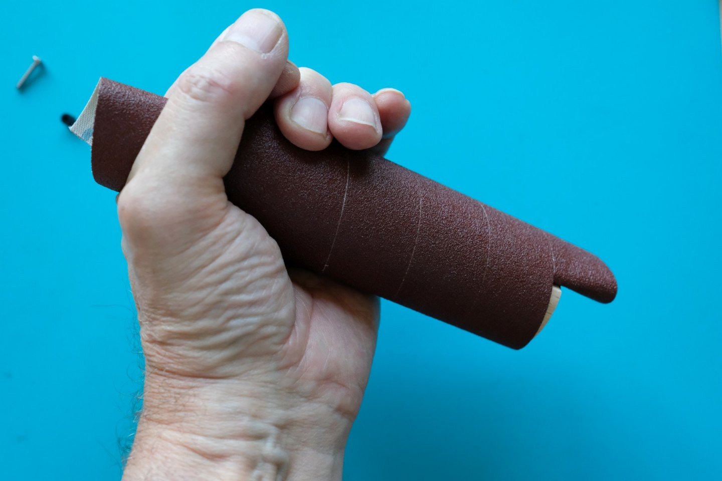
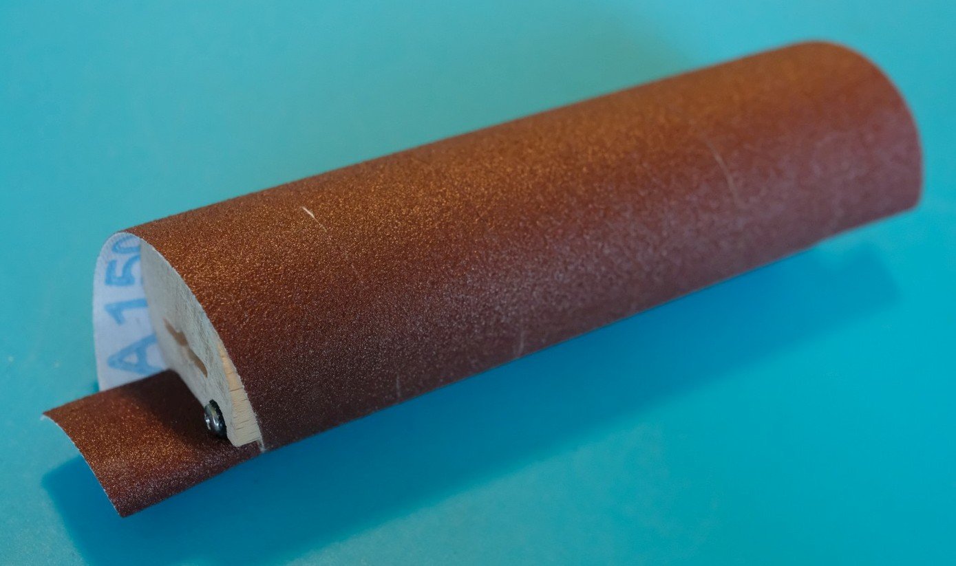
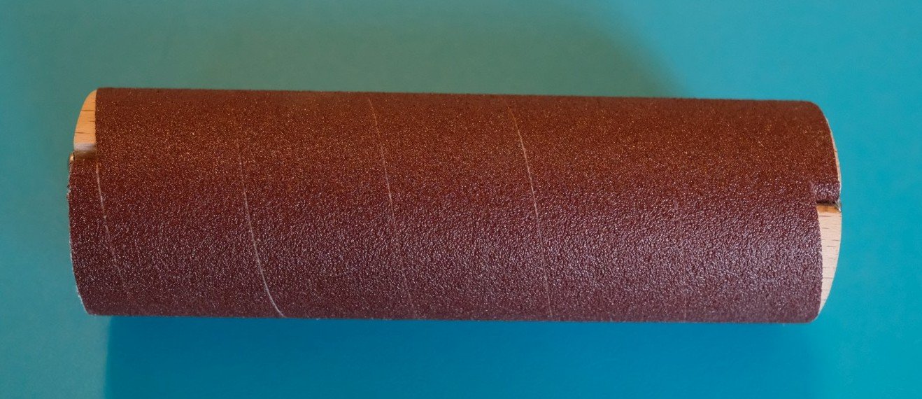
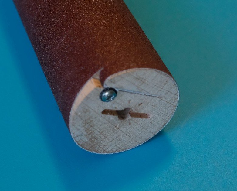
OK Bruce, you may take the front seat. For wooden model ship building you often need small pieces of wood in different thicknesses. That inspired me to develop a small drum thickness sander that would be easy to build and operate. My requirements list is however long: stiff drum to carry standard sandpaper material (no sleeves) easy mounting of the sandpaper on the drum (no gap in the drum) wide choice of grids easy drum exchange drum drive with variable speed support table that can be moved up and down while staying parallel (no tilting) precise height adjustment possible (resolution 0,05 mm) minimum sanding capacity: 100 mm wide and 20 mm thickness sanding down to 0 mm thickness should be possible efficient dust extraction When looking at this list I realize that I actually want to build my own Byrnes Thickness Sander but in a luxury edition. From the start I already had an idea of how the whole construction could be made. But before starting the build, I wanted to check if I can make a wooden drum that has a strip of sandpaper wound around it and fixed at both ends in an easy manner. So here we go. I started with looking for a suitable round piece of wood and ended up with a beech banister of 45 mm diameter and 1 m long. See next picture. I then cut this beech rod into pieces of 140 mm length. That is about the maximum size I can fix between centers in my Taig lathe. I turned it down to about 43 mm and then had to do some work at the end sides. The next image shows a 3D model of what I was trying to achieve. The narrow cut was made with a pull saw (at an angle of about 10° with the end side). It is 5 mm deep where it meets the drum surface. The rounding to the drum surface required a small sharp chisel. The centre hole of 6 mm diameter was made on the lathe and the hole touching the narrow cut is 5 mm in diameter and made in a drill stand. The groove in the middle was made on a Proxxon drill/mill stand. The result is shown next and is ready to be finished in a sanding drum. The sanding belt is 25 mm wide. I bought a box with 4 rolls of 6 m length in the grids 150, 240, 320 and 400. Wrapping the sanding belt requires a little bit of practice to get the start at the correct angle so that the turns will butt nicely without gap. Then a small piece of rubber tubing is placed in the 5mm hole and compressed with a screw so that the sanding belt is fixed. And finally the ends of the sanding belt sticking out need a cut. Done. I was pleased with the result and decided to go on with this project of building my thickness sander. best regards, Kris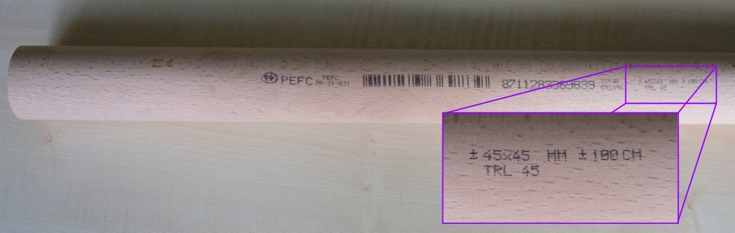

-
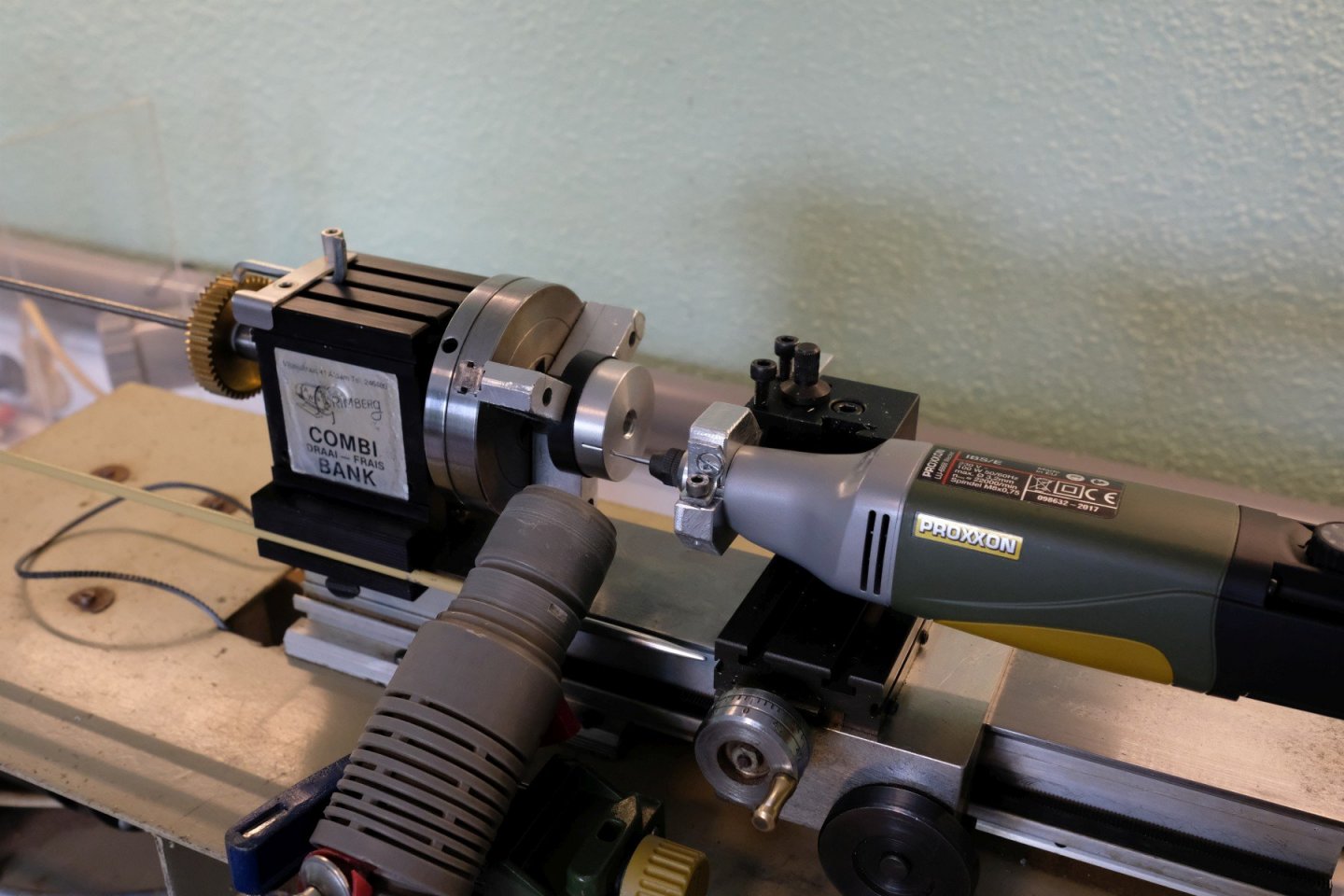
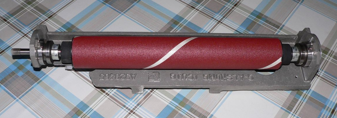
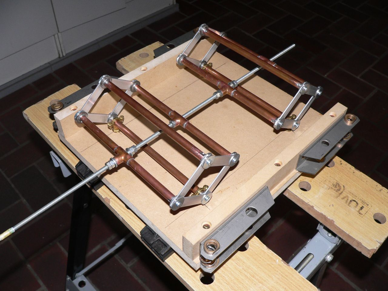
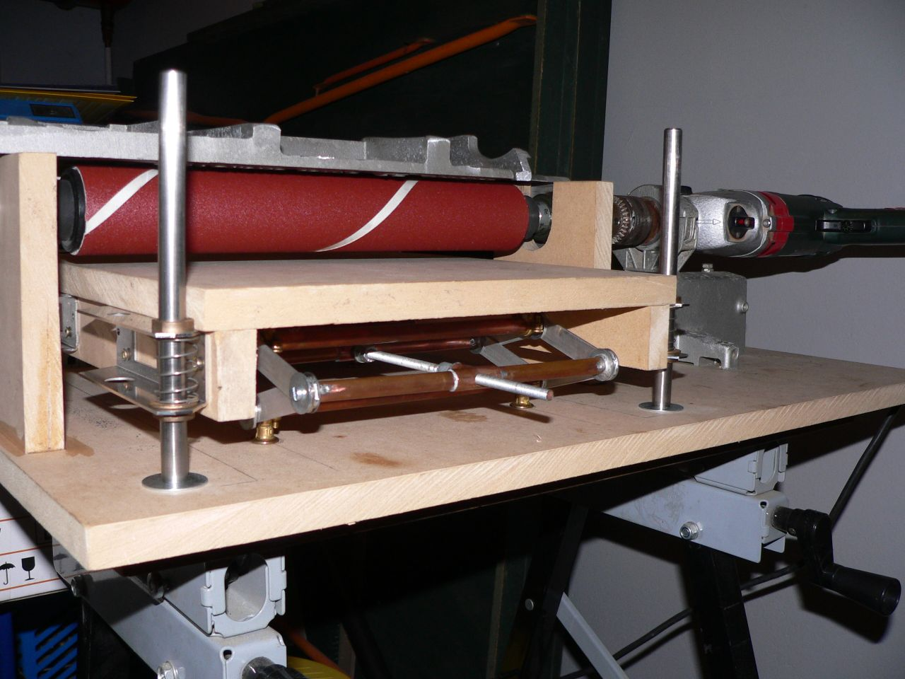
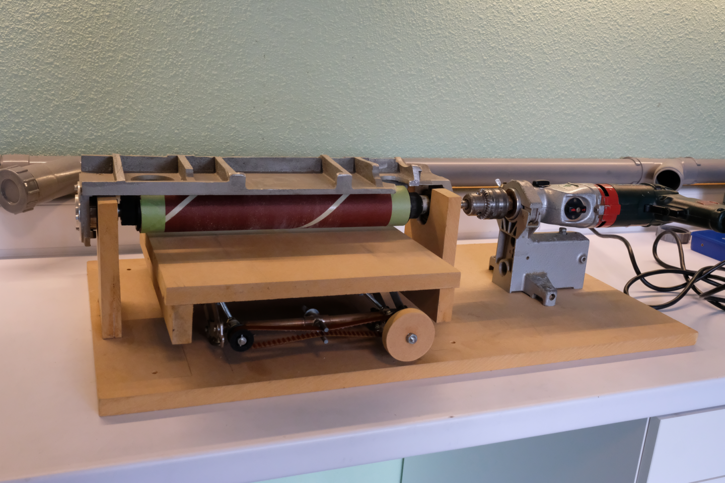
In this topic I want to report on my effort in building a thickness sander. The last few months I spend some time finishing a second attempt that finally met with my requirements. But before I show the final result, I want to tell the story of the first attempt and comment on its construction and what I learned from it. In 2010 I decided that if I ever wanted to start a scratch build, I definitely needed a thickness sander. I got the chance to have a machine part available that seemed ideal to be converted into a sanding drum. It is an aluminium cast piece with bearings holding a spindle with rubber drum ( 35 mm). The drum was made thicker with some pipe insulation foam and a plastic tube over it. Then a sanding belt was glued on with double coated tape. The next picture shows that part with the sanding paper mounted. Next I needed an adjustable height table. I constructed a double scissor type jack from some copper pipe and aluminium strip (see next picture). An M6 thread, mounted in the middle of the copper pipes served as the height control. At the side of the table I added bronze bushings that glided over some vertical pillars mounted on a base plate. The next picture shows that whole construction. The sanding drum is driven by my drill held in a horizontal fixture. As soon as tried this setup it became clear that the whole table construction was a bad design because it got stuck at the pillars very often. A little tilting of the table was enough to block it. So I needed to rework it. I removed the 4 pillars and added an extra M6 thread. These 2 M6 threads are positioned at the sides close to the scissor construction and are synchronized with a timing belt. That setup is shown in the next picture. That setup did work quite well, but: - it is (too) large - needs mounting/unmounting of the drill - makes a lot of noise - lacks dust collection and removal - renewing the sanding paper is impossible without dismantling the drum construction - height control is intuitive (same turn of the knob will not result in the same change of the height) That is it for today. Next time I will show a different design that fits better to the needs of a model maker. best regards, Kris
-
When looking at the deck pictures, I almost forget it's a model. Fantastic detail and superb metal work.