Kris Avonts
-
Posts
113 -
Joined
-
Last visited
Content Type
Profiles
Forums
Gallery
Events
Everything posted by Kris Avonts
-
Hi Tony, The micrometer shows no play nor backlash, so it should be precise up to 0.01 mm. I paid much attention to mounting the support very level both horizontal and vertical. In order to make the fit between the proxxon body and the support almost perfect, I filed the rounding by hand. But that was not perfect, a little tilting was still possible. So I decided to use some metal epoxy glue on the edges of the support and stretched some plastic kitchen foil over the proxxon top. After positioning the support on the plastic, I checked with a level tool and let the glue harden overnight. That resulted in an almost perfect fit without play. I still have to test its actual precision. As you might know 'the proof of the pudding is in the eating'. Kris
-
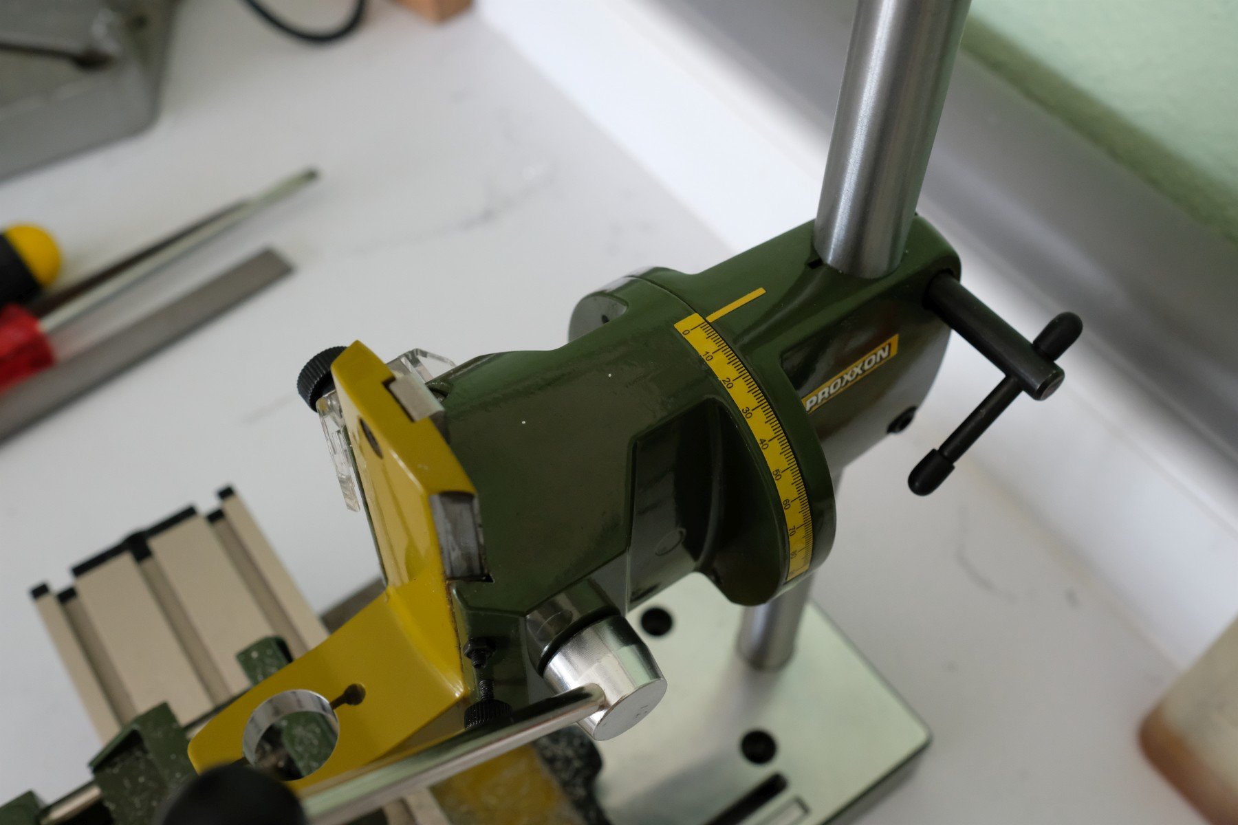
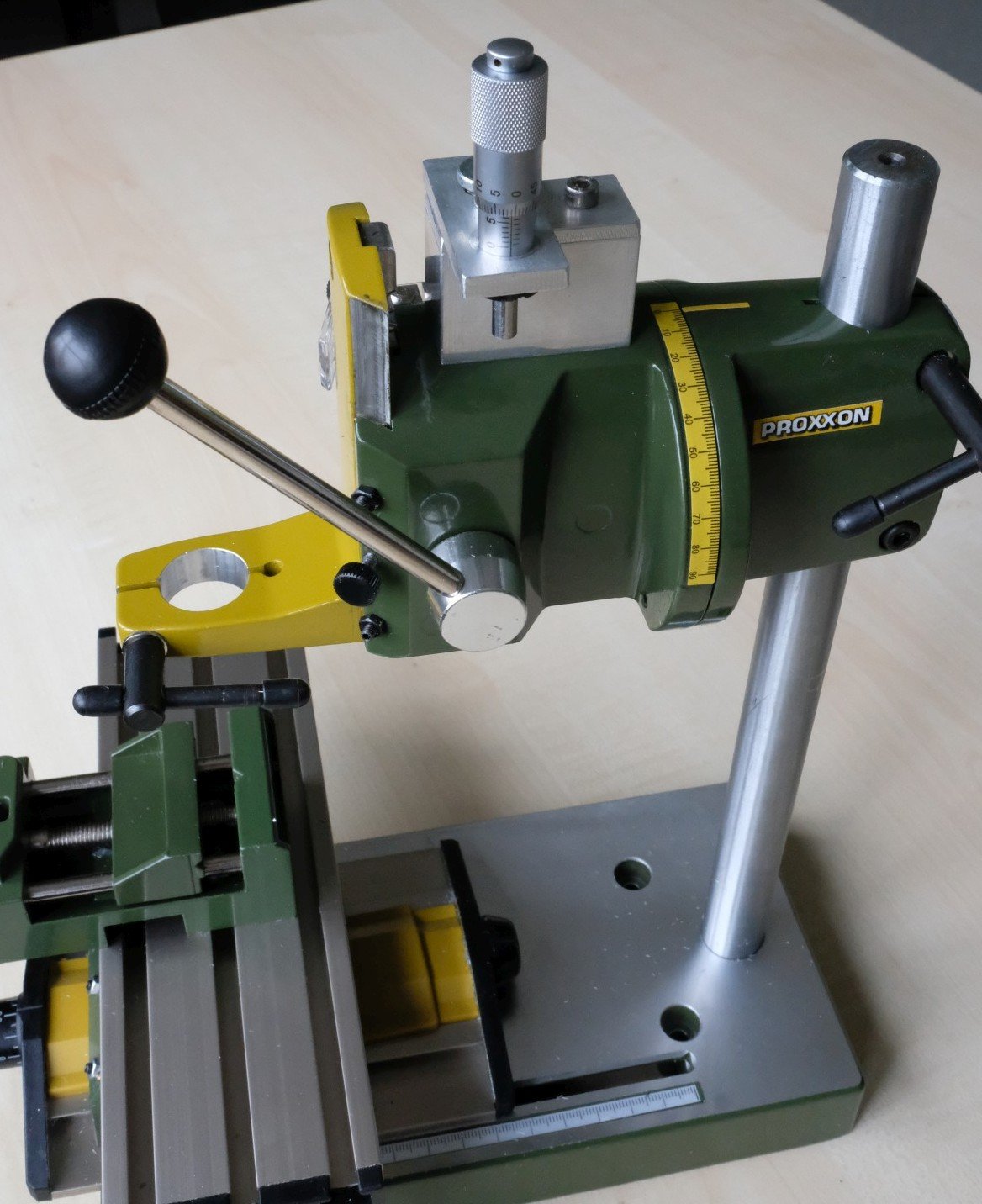
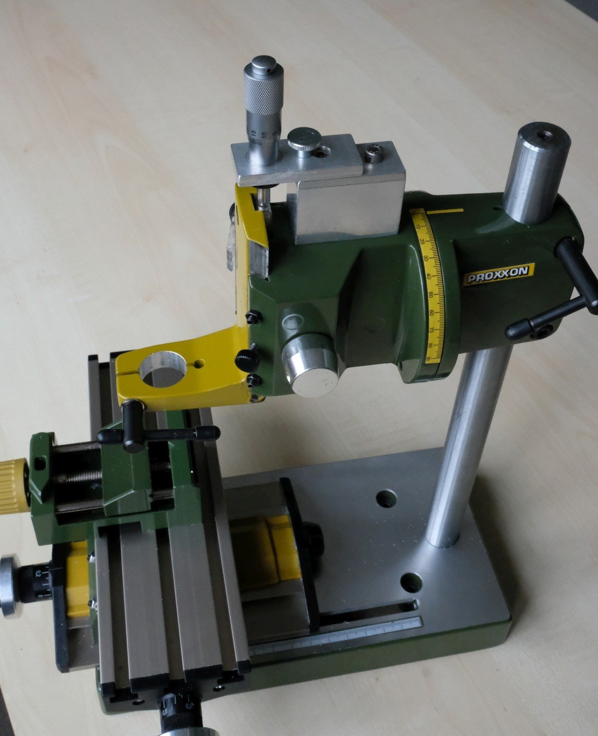
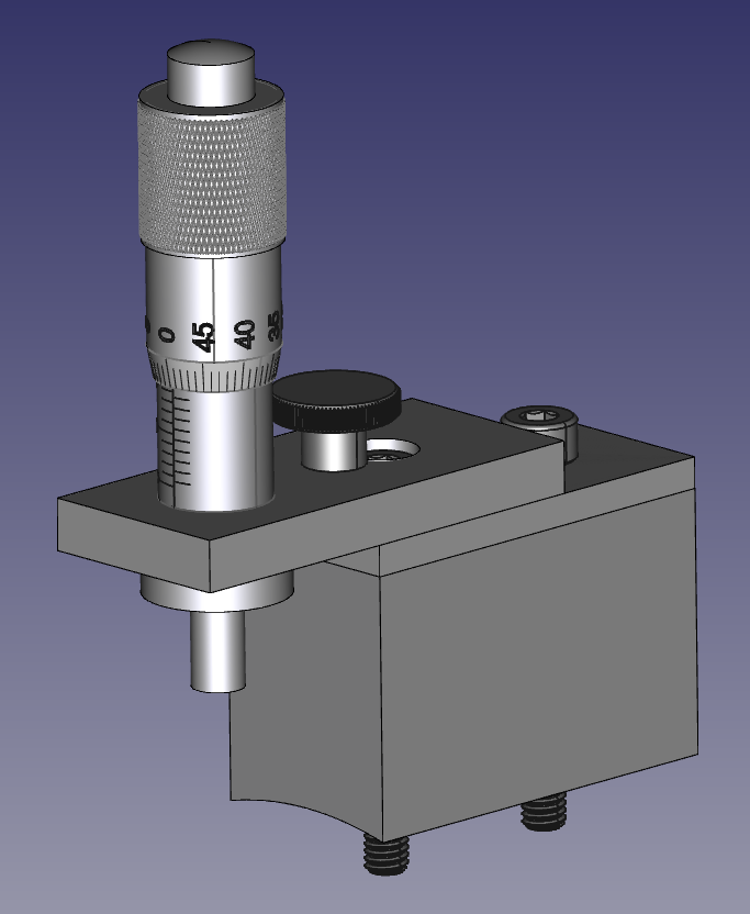
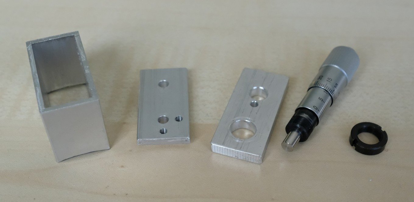
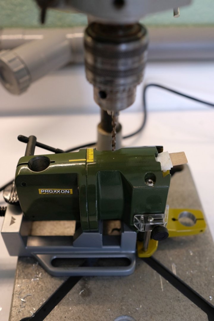
I have an MB200 drill stand from proxxon and I mostly use it for precision milling work. As a drill stand it only has a handle to do the setting of the depth that is indicated by a mm scale. For small depth settings below 1 mm it becomes difficult to adjust the depth to the wanted value. So I decided to improve the MB200 and fit an auxiliary depth feed screw on top. AS depth feed screw I use a micrometer head with 13 mm range (bought in China for 9 euro’s, but works very well). All the other parts to fix it on top of the MB200 are aluminium that I had available (piece of 40x20mm rectangular profile, 2 mm thick and some 5 mm thick flat extruded profile). Here is a model of what I tried to make. It is just a support (the rectangular alu profile) that needs an inside rounding at its bottom to fit the die-cast aluminium body (R=40 mm) of the MB200. On top of that there is a lid with 2 holes (20 mm apart) to mount the support with 2x M4x35 to the body. It also has 2 holes with M3 thread to fix the micrometer holder plate in 2 positions. Here are the machined parts. Next you see the MB200 with the 2 marks where a thread M4 is to be made and in a larger drill stand just before drilling with 3.3 mm. Then I only need to show the end result. The micrometer head can be mounted in 2 positions. Straight for milling and at 90° for drilling. For milling I remove the handle and after a depth adjustment you always need to lock the set screw of the dovetail again. I hope anyone in need of fine milling and owner of a proxxon MB200 can find some inspiration here. Best regards, Kris Avonts


-
《DIY tools for personal use》Sand disc
Kris Avonts replied to Bitao's topic in Modeling tools and Workshop Equipment
Hi hyw, That's a nice piece of machinery. Based on the size of the square (250x160) I estimate the sanding disk to be 125 mm in diameter. The table is 200x100 mm (?) and sits on a linear guiding rail, but how do you tilt it? And a last question: this seems to be a 3-phase AC induction motor with frequency converter, but what is its power rating. It looks quite heavy for working with wood pieces of the size most used by modellers. Anyway... this is well done. regards, Kris -
If you are looking for mica, take look here: I tried to cut mica and found that you can also split it into thinner pieces (kind of peeling off). Then it also gets easier to cut with a knife, chisel or scissors. To find where you can buy mica as it is used in electronic circuits, just google 'TO-3 mica insulator'. regards, Kris
-
Making extremely tiny fittings
Kris Avonts replied to BETAQDAVE's topic in Metal Work, Soldering and Metal Fittings
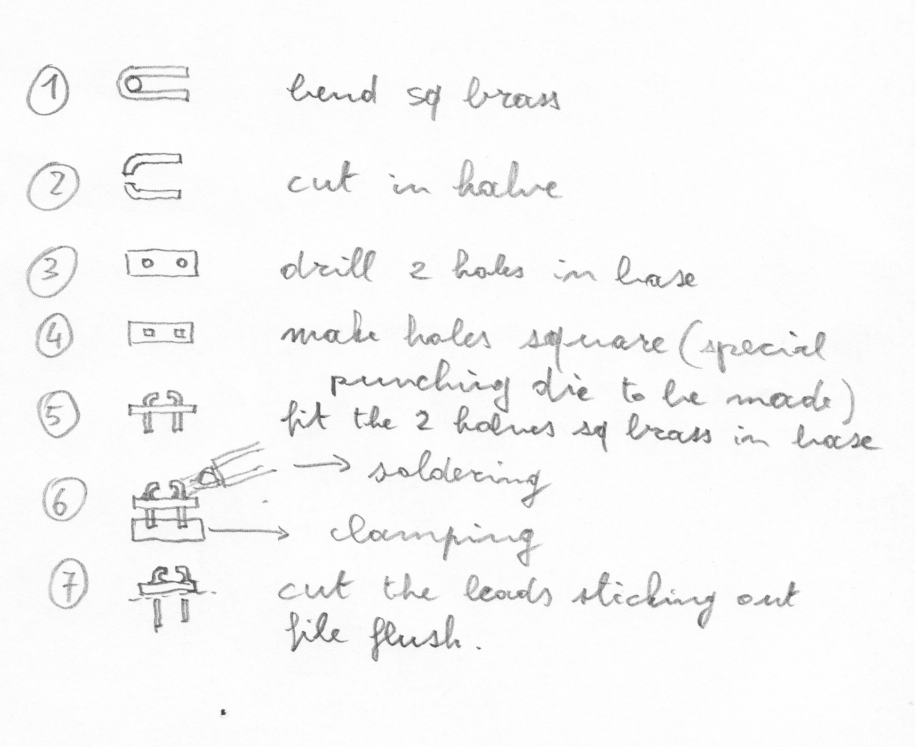
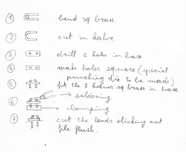
Hi Dave, Indeed small parts are a real challenge. In your case I would do the following steps: Its just an idea, I have no experience with soldering such small parts. best regards, Kris
-
Glazing
Kris Avonts replied to Kurt Johnson's topic in Discussion for a Ship's Deck Furniture, Guns, boats and other Fittings
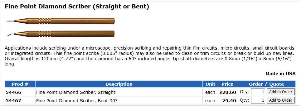
Mica is a good choice if you can find some clear samples. They are still used in electronic circuits to (electrically) isolate power transistors from aluminium (aluminum for the US folks) heat sinks. So you can find them in shops where they sell electronic components (or the internet of course). Most popular will be isolation sets for TO3 or TO220 style packages for power transistors. Here are some sample pictures. A typical TO220 mounting kit: These mica plates are 13 by 18 mm and about 0.15 mm thick. Also a remark on cutting the thin glass cover plates. If you want to cut these you need a fine point diamond scriber. Something like this: With some practise it should be possible to break the glass with a straight cut. During good scribing you can hear the glass cracking by the heat generated at the contact spot. It should not break however. Then turn the glass over (scribe down) and place on a flat surface of material that is slightly compressible. Place a small (ground) metal rod over the scribe and press it down gently.... crack, your plate is split. so far my 2 cents on this topic, best regards, Kris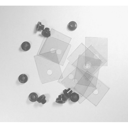
-
Need CAD type program
Kris Avonts replied to Sambini's topic in CAD and 3D Modelling/Drafting Plans with Software
Well Ab, you can pass my thanks to Rene also. And you deserve also credits for showing us these tricks so clearly. For me this is a real eye opener of what is possible with DELFTship. best regards, Kris -
Exploring FreeCAD for ship modeling
Kris Avonts replied to TonyM's topic in CAD and 3D Modelling/Drafting Plans with Software
As I further explore FreeCAD, I want to share the next simplification to my proposed method in post #10. The polylines of 2 segments can be dropped completely, just constrain the three control points of the spline with symmetry. That will bring them all three in line and then you can make the middle one coincident with the target (offset) point. Done! The more I explore FreeCAD, the more I start liking it. Its GUI with the different workbenches is a bit awkword and not as coherent as a commercial product but it's free software and all files stay yours. I hope this helps some more FreeCAD users. best regards, Kris -
Exploring FreeCAD for ship modeling
Kris Avonts replied to TonyM's topic in CAD and 3D Modelling/Drafting Plans with Software
You go really fast TonyM. But you should when I read about all your plans. Especially the idea of use 3D-printing to make jigs or plug is appealing to me. My intentions on the other hand are a little different. I want to reconstruct the hull in 3D based on an existing ship plan by using as much as possible the same construction techniques that the original artists uses. For instance if I know that the bottom of a frame consists of 3 sweeps (arcs), I will draw 3 sweeps and no spline. I'm sure it will my 3D work harder but I will give it a try. best regards, Kris -
Exploring FreeCAD for ship modeling
Kris Avonts replied to TonyM's topic in CAD and 3D Modelling/Drafting Plans with Software
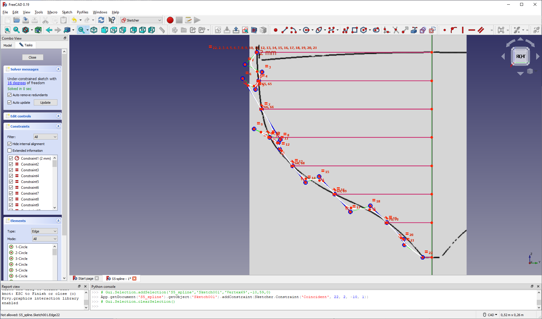
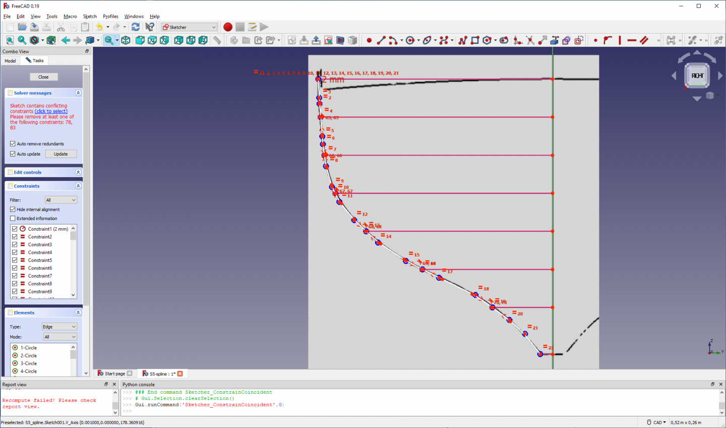
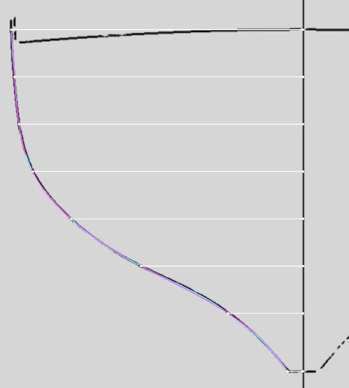
In addition to my sketcher B-spline workaround I have to warn that the curvature of the resulting spline is much less fluent then the one that is drawn with the multiple-point B-spline tool from the draft workbench. See the next screenshot (magenta is draft spline curvature, blue is sketcher spline curvature). The explanation is simple. The points from the sketcher spline that I made coincident with the offset points all have zero curvature in that point. In a fluent curve zero curvature should only be present in inflection points where curvature switches its sign. The general curvature trend along the spline is however almost identical. So if you don't seek the utmost curvature smoothness, the sketcher spline will do fine because it maps very close to the station line. all the best, Kris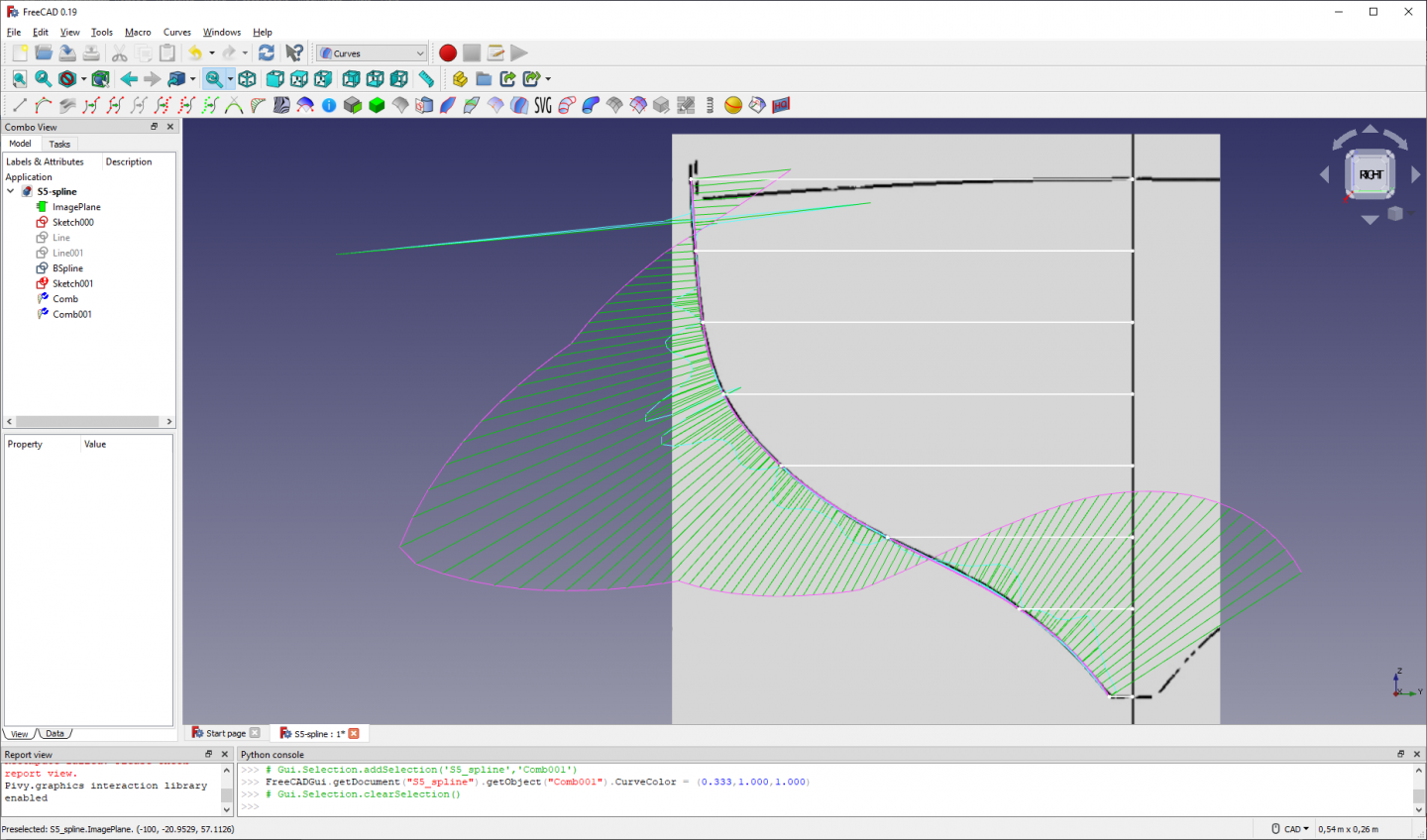
-
Exploring FreeCAD for ship modeling
Kris Avonts replied to TonyM's topic in CAD and 3D Modelling/Drafting Plans with Software
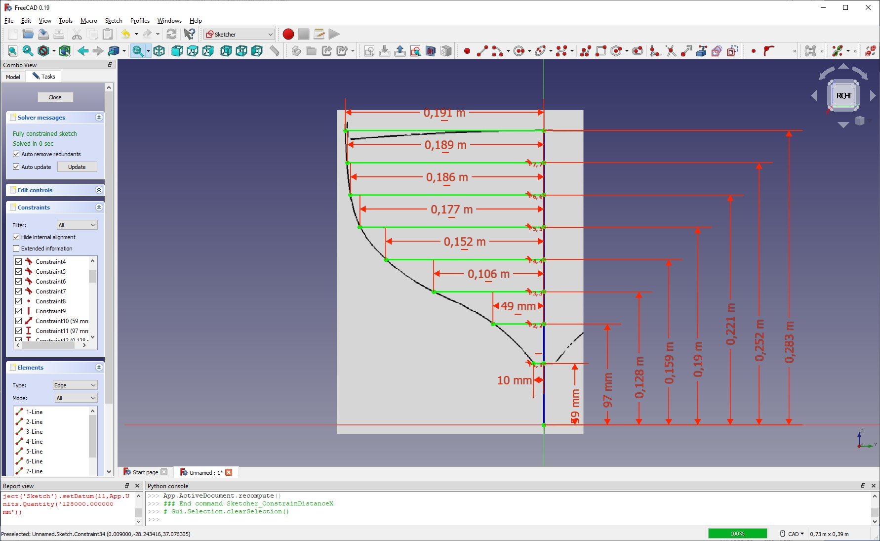
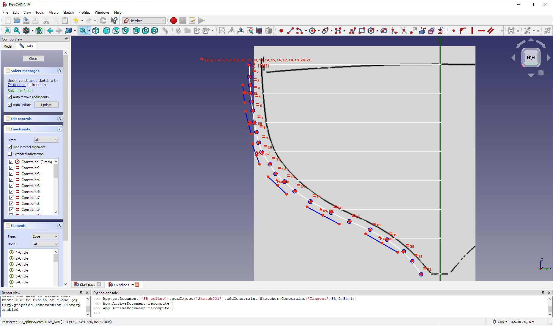
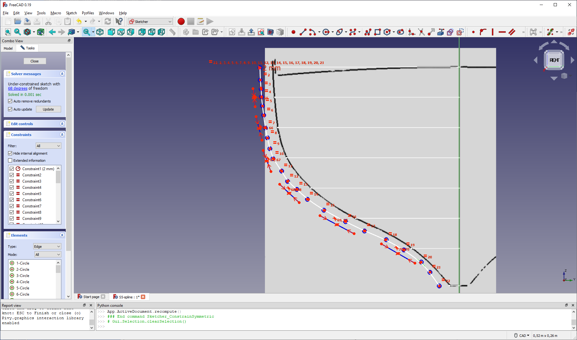
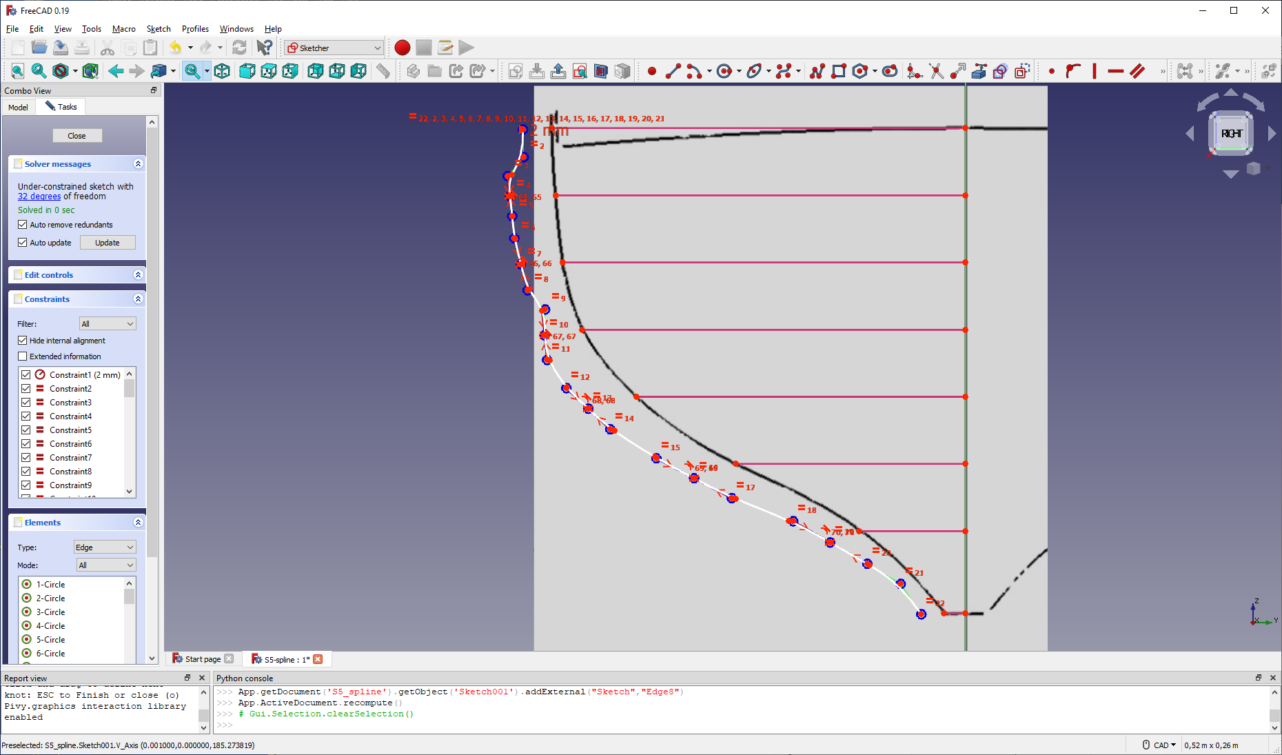
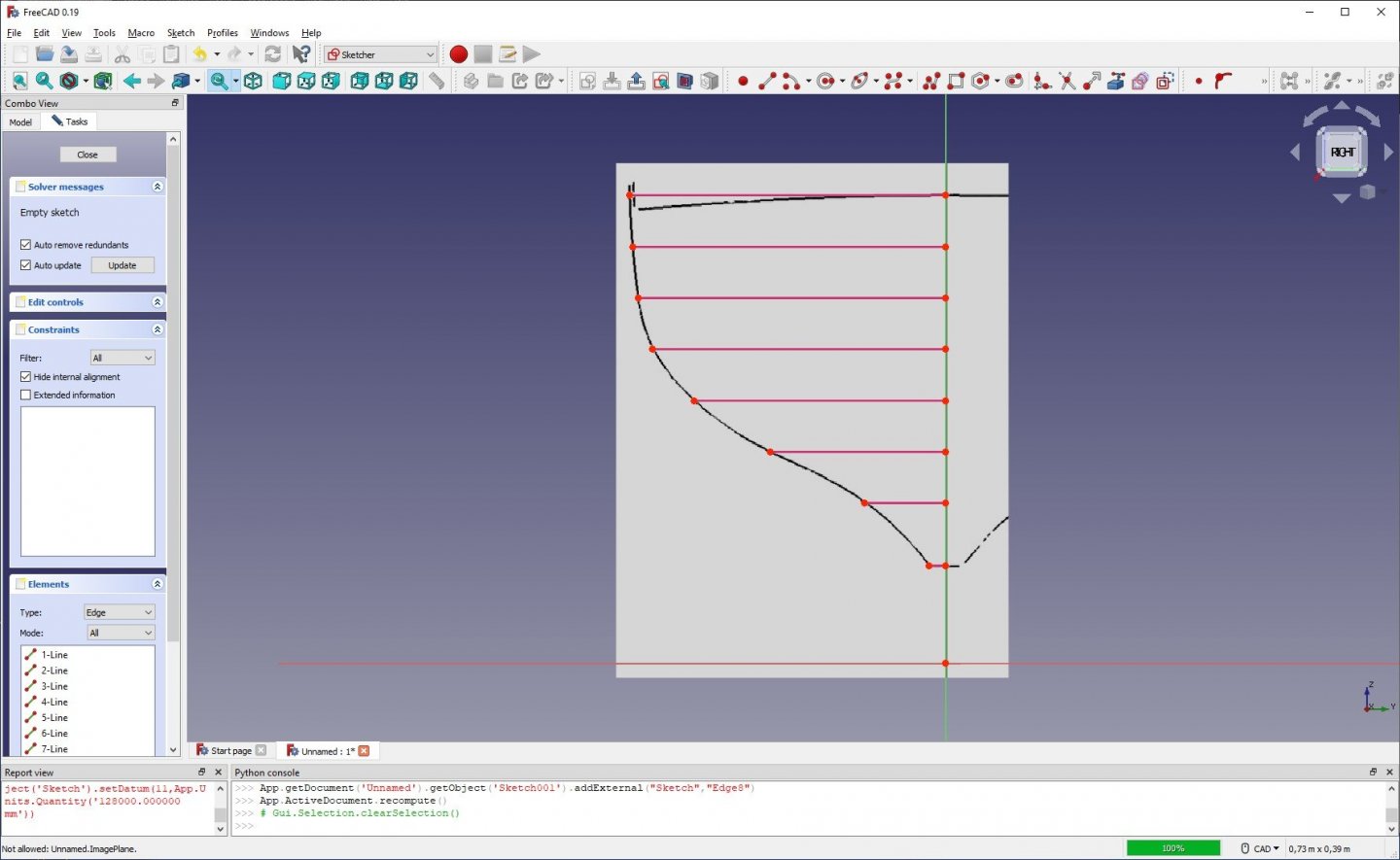
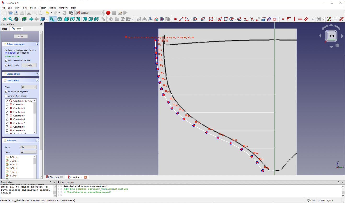
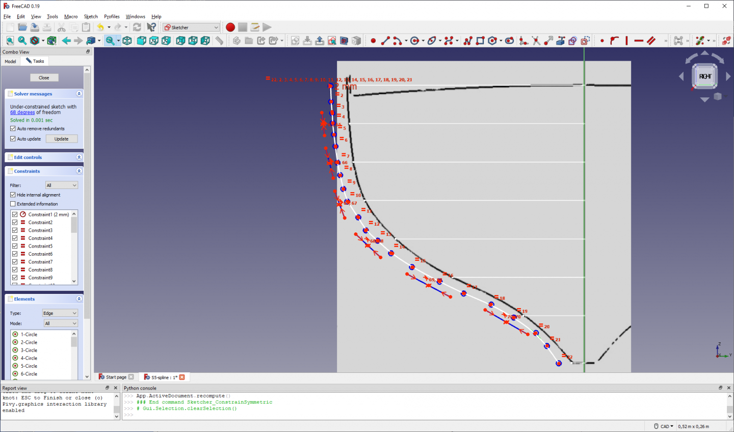
Hi TonyM, I think I can show you a way to get the splines for the stations to pass through your offset points. I also do it as an exercise for myself to get more confident with the sketcher and/or draft workbenches and their capabilities. First I extracted station 5 from one of your screenshots, removed most of the background and inverted your resulting white B-spline to black. That image was then imported in FreeCAD with the image workbench, scaled and moved. I scaled to some arbitrary size so I could use your numbers for the position of the offset points in mm units. Then I started sketch000 to define your offset points. The vertical line is a polyline with its lower point at the origin (coincident constraint) and then vertical distance constraints for every other point are added. Next are the horizontal lines added to reach your offset points. To make the desired B-spline, I started a new sketch, sketch001, and imported the horizontal lines from sketch000 as external geometry. Now the actual work can begin. First I tried the work around form the FreeCAD forum I mentioned in the topic ‘Need CAD type program’ (https://forum.freecadweb.org/viewtopic.php?t=30180#p249022).That was a disappointment because it resulted in lots of errors being reported and even complete crashes (stop reacting) of the FreeCAD program. Then I invented my own work around that I will describe next. Draw a B-spline along the profile of the station. Start with a point at the top about the same height as your highest offset point, then 2 intermediate points are placed on the way to the next lower offset point. Then 1 point next to the offset point. Again 2 intermediate points on the way to the next offset point where again 1 point is placed and so on until you reach your lowest offset point. This results in 22 control points in this example. Then I switch to construction mode and draw polylines of 2 tangent (press 2x M key between 1st and 2nd line) segments along the spline at each offset point except the highest and lowest. Now I constrain each polyline with symmetry. Next I constrain all polyline points to be coincident with the corresponding spline control points. Now we can put the spline over the station line by a coincident constraint for the endpoints and the points that correspond to offsets. That looks awful but we can touch up the spline by moving the intermediate points into position until our spline pleases the eye. The result looks like this. Now you have a sketched station line that passes through your offset points. Just to compare, I also used the draft workbench to draw a B-spline through points with the end-line snap active. You see the draft B-spline in magenta colour and the sketcher B-spline in light blue. They are almost identical. For me this was a pleasant exercise and I hope you can use some hints from this example to refine your model. Best regards, Kris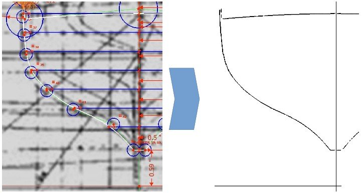


-
Exploring FreeCAD for ship modeling
Kris Avonts replied to TonyM's topic in CAD and 3D Modelling/Drafting Plans with Software
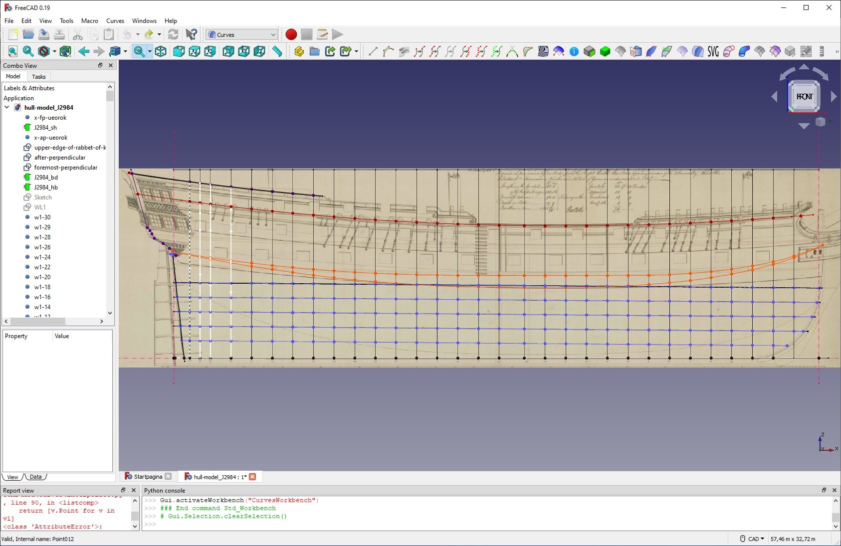
I want to share the current state of my FreeCAD work. It is for an English third rate ship (74-gun) from the second half of the 18th century. I must admit that it is a far too complex ship to start with, but my desire to bring such ship to live won from logical reasoning. Here we go: It is just a bunch of points. I used both draft points and part vertices. The exact difference between the two kinds is unclear to me. They are arranged horizontally along the waterlines, half-breadth lines, top-timber line and topside. Vertically they follow the location of the stations. The next picture shows this more clearly. I made curves through these points both with draft splines and the tools from the curves workbench. I wanted to use the Gordon-surface tool from the curves workbench to skin the network of curves. That was a disappointment and only resulted in errors. My network of curves, that looks quite OK visually, is far from a real network because intersection points of horizontal and vertical curves are actually not coincident. I think you can only get that by using sketches that import these intersection points from external geometry (sorry if this sounds very FreeCAD slang). My tree-view of this model also lacks structure and that makes it difficult to keep track of more then 300 points already. Conclusion: I will try to start over the effort and use sketches from the start. best regards, Kris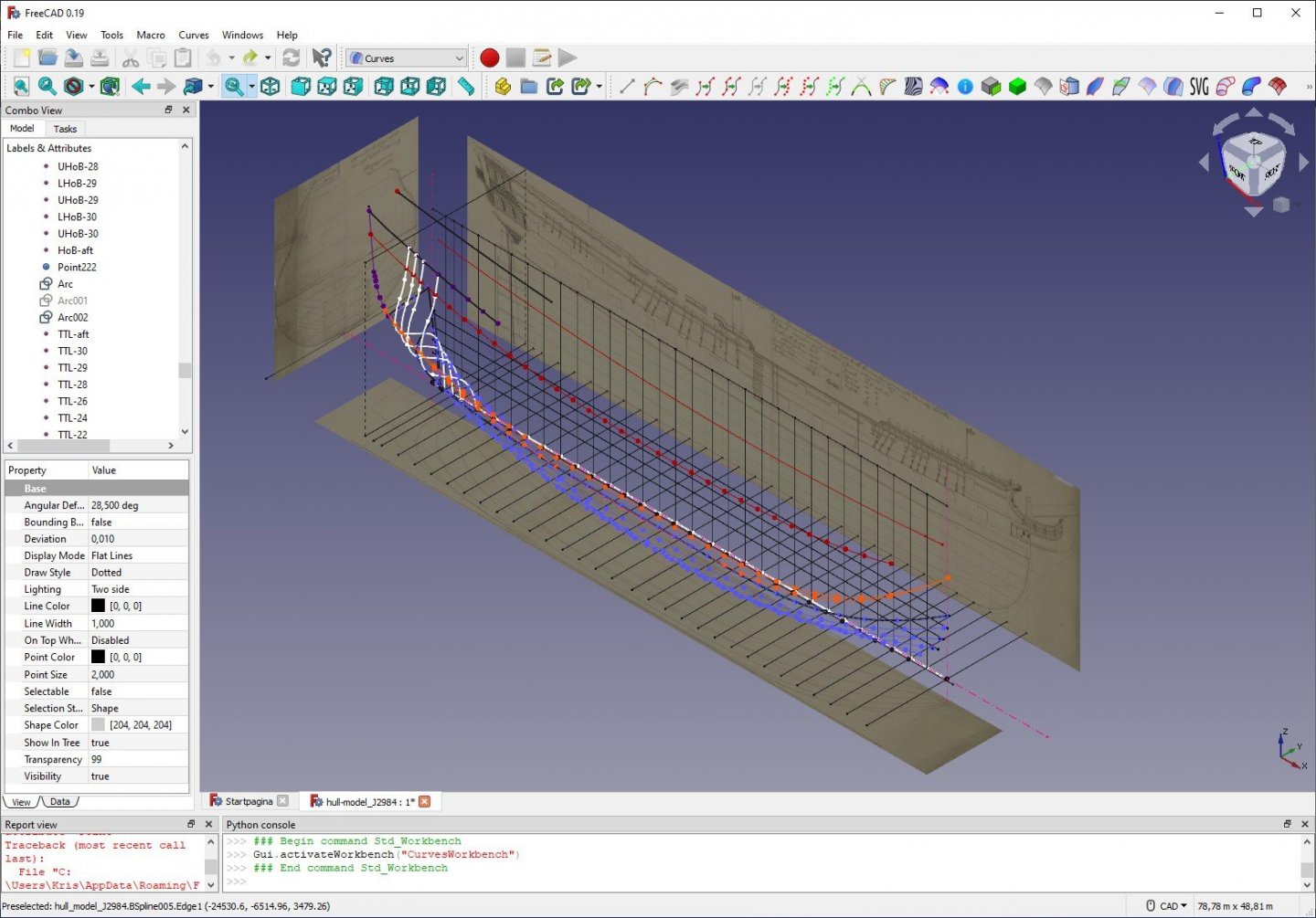

-
Need CAD type program
Kris Avonts replied to Sambini's topic in CAD and 3D Modelling/Drafting Plans with Software
Yes, that is a traditional start with DELFTship. I guess the tricky parts to map the model to the lines of an existing (ancient) ship plan will follow. Anyway thank you for starting this effort. best regards, Kris -
Need CAD type program
Kris Avonts replied to Sambini's topic in CAD and 3D Modelling/Drafting Plans with Software
That is fantastic news, Ab. I can hardly wait to walk around in that virtual ship. And the fact that it took 3 years for that model makes me realize that I have to spend some more effort. thanks and regards, Kris -
Need CAD type program
Kris Avonts replied to Sambini's topic in CAD and 3D Modelling/Drafting Plans with Software
Hello Ab, If what you show is made with DELFTship, I call that a masterpiece. I also have used DELFTship but never realized the lines I wanted. Maybe I miss the point with DELFTship because I believe that every point that you make is a control point. So it is not a point on the hull. From the control points, lines for a hull are made by subdivision and you can adjust these lines by moving around with the control points. Every movement of a control point will affect several hull lines. For me that resulted in overly adjustments and a lot of frustration. Maybe I should give it a second chance as you prove that DELFTship can be mastered. best regards, Kris -
Need CAD type program
Kris Avonts replied to Sambini's topic in CAD and 3D Modelling/Drafting Plans with Software
Hi TonyM, I also have tried out FreeCAD to model a hull. But until now that was not very successful. I even have problems of making points from the waterlines in the half-breadth plan to coincide with the same points viewed in the station lines of the body plan. About the splines in the sketcher, it is a fact that you can only make constrains for the control points and not the points of the spline itself. There is however a workaround for this and it is explained in this video: https://forum.freecadweb.org/viewtopic.php?f=10&t=9364&start=420 It seems a lot of extra work to me. So if you start a topic showing some hints on how to construct coincident points, I'm interested. best regards, Kris -
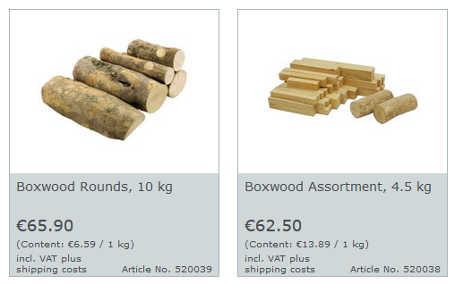
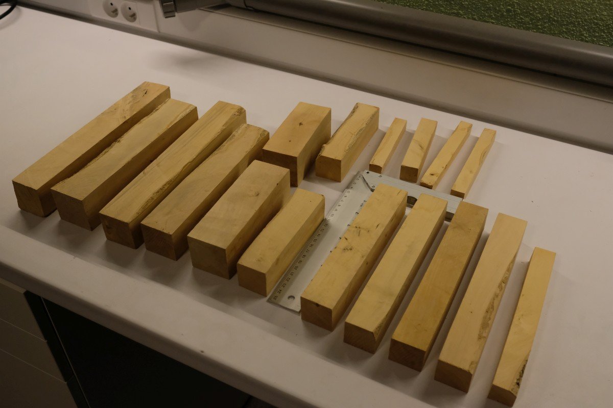
Hello j (Hardwoodhorder), I bought some boxwood about 2 years ago from Dictum, a German company that sells tools for the woodworker. They also offer a range of materials where you can find 2 offerings for boxwood. See here: https://www.dictum.com/en/european-wood-caa?p=5&followSearch=9700&o=1&n=12 The 2 last items in the European woods section are boxwood: The boxwood I ordered is no longer on display on the Dictum website. It was called ' Buchsbaum-Kantelsortiment, 4,5 kg '. Its cost was 55 euro and this is what I received: The largest pieces are 50 mm square and the longest is about 270 mm. The smallest are 20 mm square and the shortest is about 120 mm. You can see that some edges show some remains of bark (I turned all such edges up for the picture). Also take into account that there are shipping costs as weight is 4,5 or 10 kg, and it depends where you live. I paid 16,80 euro for shipping to Belgium. I hope this information is useful for anyone looking for boxwood in Europe. Best regards, Kris