


Captain Al
-
Posts
613 -
Joined
-
Last visited
Content Type
Profiles
Forums
Gallery
Events
Posts posted by Captain Al
-
-
Is there a type of clamp that can be used to hold the ply deck down on the tops of the frames while glue dries? I can't figure out a way to do this. It would have to be sort of a T clamp. I have a deck to glue down on Bounty that has a good deal of sheer to it and a couple of the aft most points of contact with the frames require a bit of push to get them to sit down. I am using weights on six other points but these particular frames would require more weight than I want to place on the model itself. I was considering putting small shims on the tops of the frames so the deck doesn't need to curve down as much, but this would not only change the sheer of the deck but would require some additional wood on top of the cross beam. And of course, a pin down into the frame could do the job as well. But my first priority would be to clamp down. Any suggestions?
-
Thanks all. I have a niece who is an orthopedic surgeon. Maybe she'll send me her used scalpels. And all other suggestions will be tried. Especially the glove. My nephew ( husband of the niece) is the head MD at SF General ER, and he has warned me several times about that.
-
I am using brand new exacto blades to cross cut .6mm x 5 mm rawmin, and I am wondering why it is so difficult. Is it just my expectations as to how easily the cut should be made, or are these blades just not sharp enough, even though new? Is it best to make several light passes over the wood or one pass pressing down hard. Cutting through this material I find a sharp scissors does the job better. If not Exacto, is there a better option for a cutting knife; maybe a scalpel?
-
Watching your work come together is like watching a great movie. thanks for sharing with us.
-
Good to know. Can't wait to see it and start using it. Thanks for the confidence builder.
-
I just ordered a used copy from Amazon. Thanks for the tip Brian. I hope that when they say "good" condition that their definition of good is about the same as mine.
-
No kidding? I didn't see that. Thank you. This is one time I would opt for the used copy. Thanks again.
-
Found it on Abe Books (great website btw) but they wanted more to ship to the US than they do for the book itself. Total around $80. I'll have to keep looking at that price.
-
Brian, I'm in the States, but thanks for the offer. Maybe next time I'm down under I'll call on you.
Dave, I've never heard of Abe books but I'll google it. Thanks for the suggestion.
-
I've ordered it from Amazon for about $25, but its been on back order for over a week now. I would really like to get my hands on a copy sooner than later; new or used. Any suggestions?
-
So thinking I was now pretty much done with the interior and I could move on to installing the main deck beams and planks, I discovered that I was facing the biggest challenge to date: "the horror; the horror." Fans of Brando will excuse my trite use of his words.
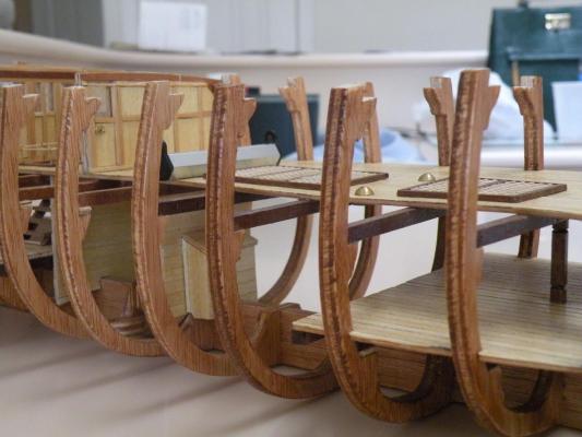
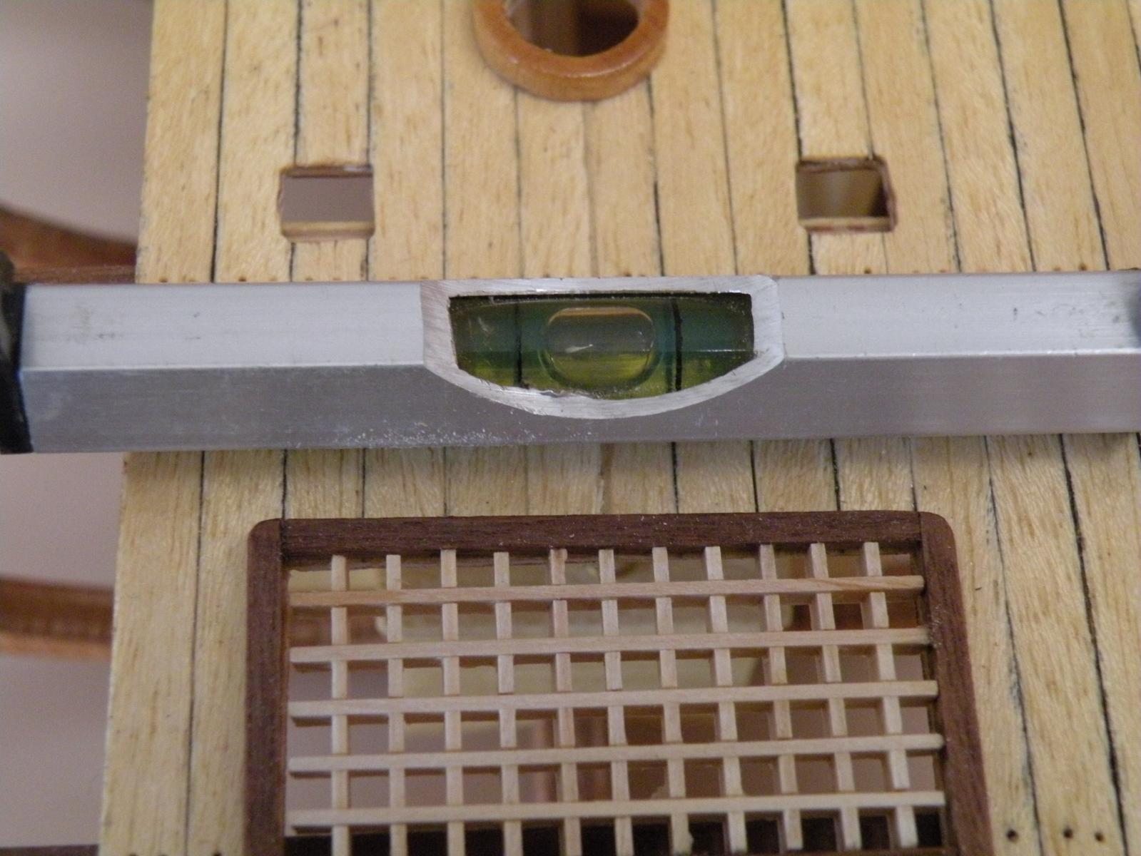
I'm testing the main deck and wondering how much "adjustment" I will need to make to fit it cleanly into the slots. When I lay it on top of the frames (without beams) I find to my dismay that not enough care went into the framing. There are many frames that are (1) too high on one side and too low on the other, and (2) not spaced precisely. If I were to lay the deck down it would more resemble moguls on a ski slope. I know I have to fix this problem and I have been mulling over the process I would use. I recognize that the process of fixing these frames should have been employed in installing them in the first place. I should have not trusted the fact that they slipped into their slots cleanly, fully and at right angles to the keel. I should have read the plans and noted the spacing and their heights and taken steps to make sure they conformed. I was in a hurry and I'm paying the price now.
So first off I've gone to the plans and measured the height from the bottom of the keel to the point where the beam will fit into each one. I went through a laborious process of measuring what the actual, in place, height of my frames are. I thought I'd compare the two figures to know how much to add in the way of shims if too low and how much to sand or cut off if too high. Then I realized it made no difference. Better to simply set the model on its keel, perfectly level side to side, and make a mark where the top should be, showing where I needed to cut or sand to. For those that are too low and have nowhere to mark, I will use the other method to add a little. As for the spacing, which isn't all that bad, I might cut spacers to the precise length and set them between the frames. That will kill two birds with one stone, giving me a little more surface to glue a plank to. But on the open side of the ship I don't know how it will look, and don't know if it will be necessary to keep them in once the deck is down.
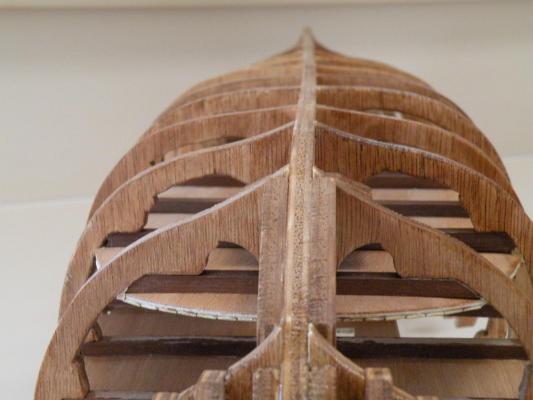
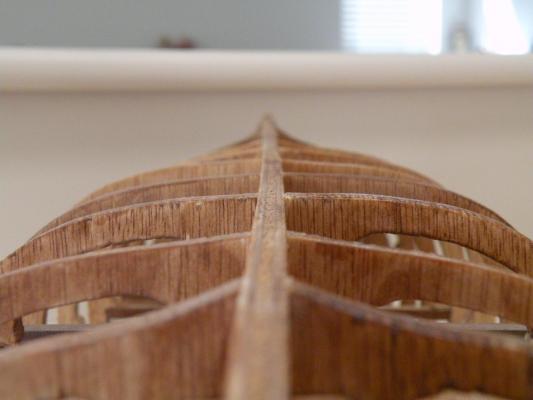
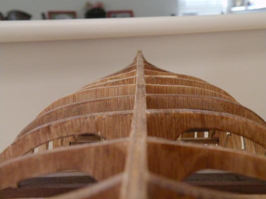
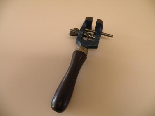
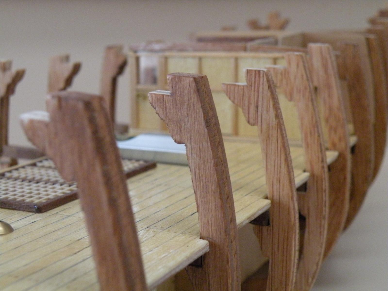
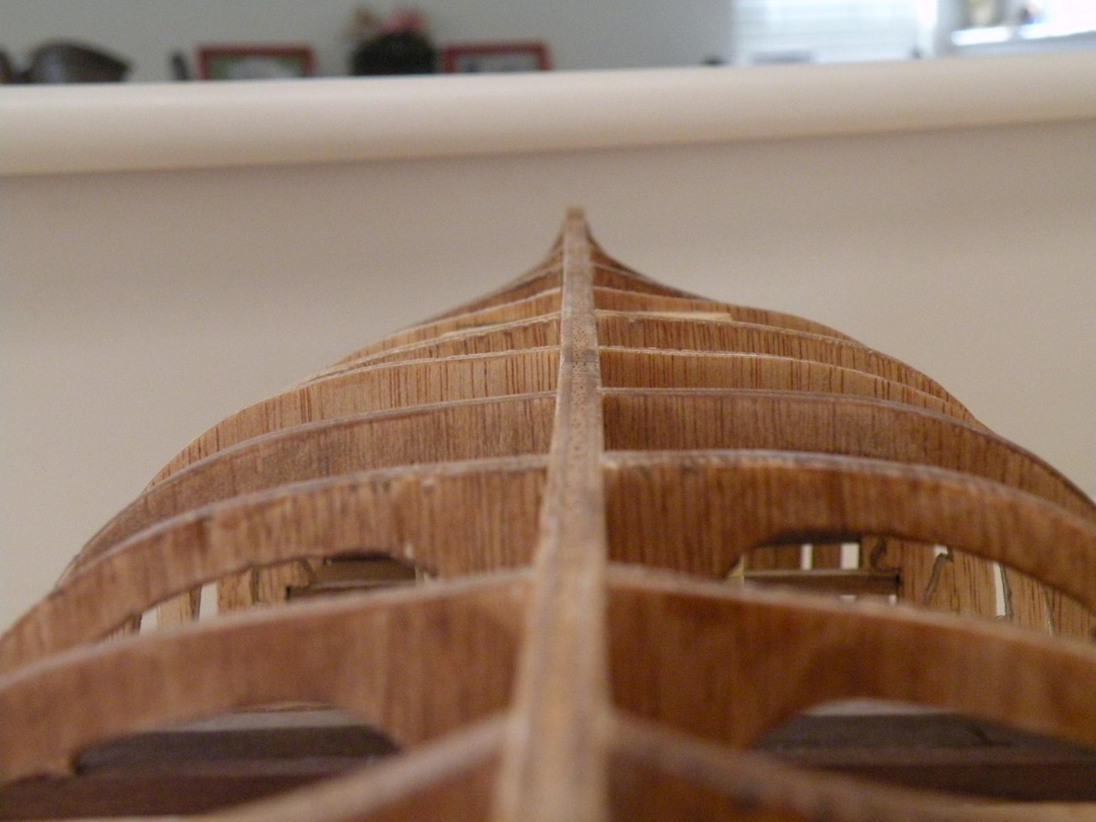
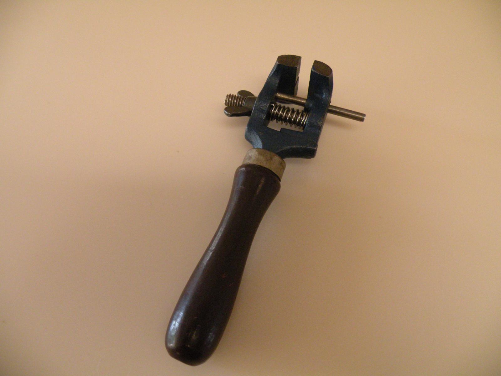
I hope all this works out satisfactorily and I can get the deck on without using a sledge hammer. And, as shown in the pic below, I know there is a bow to the keel itself which will present problems in planking. But that is for another day. I welcome any and all suggestions as to methods to use in cutting, sanding and adjusting these frames. Another great find in my garage is a little hand vise that dates from the 1950s when my Dad was into model railroading. Set into my table vise I can position it to hold each frame secure while I sand, cut or file.

-
Well, just to show that my time isn't totally wasted in theoretical mish mash, I will describe my progress and post photos as well.
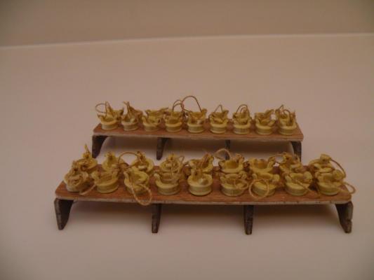
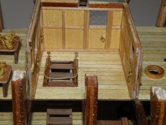
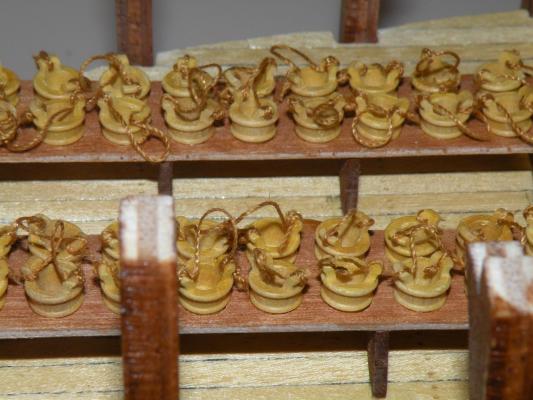
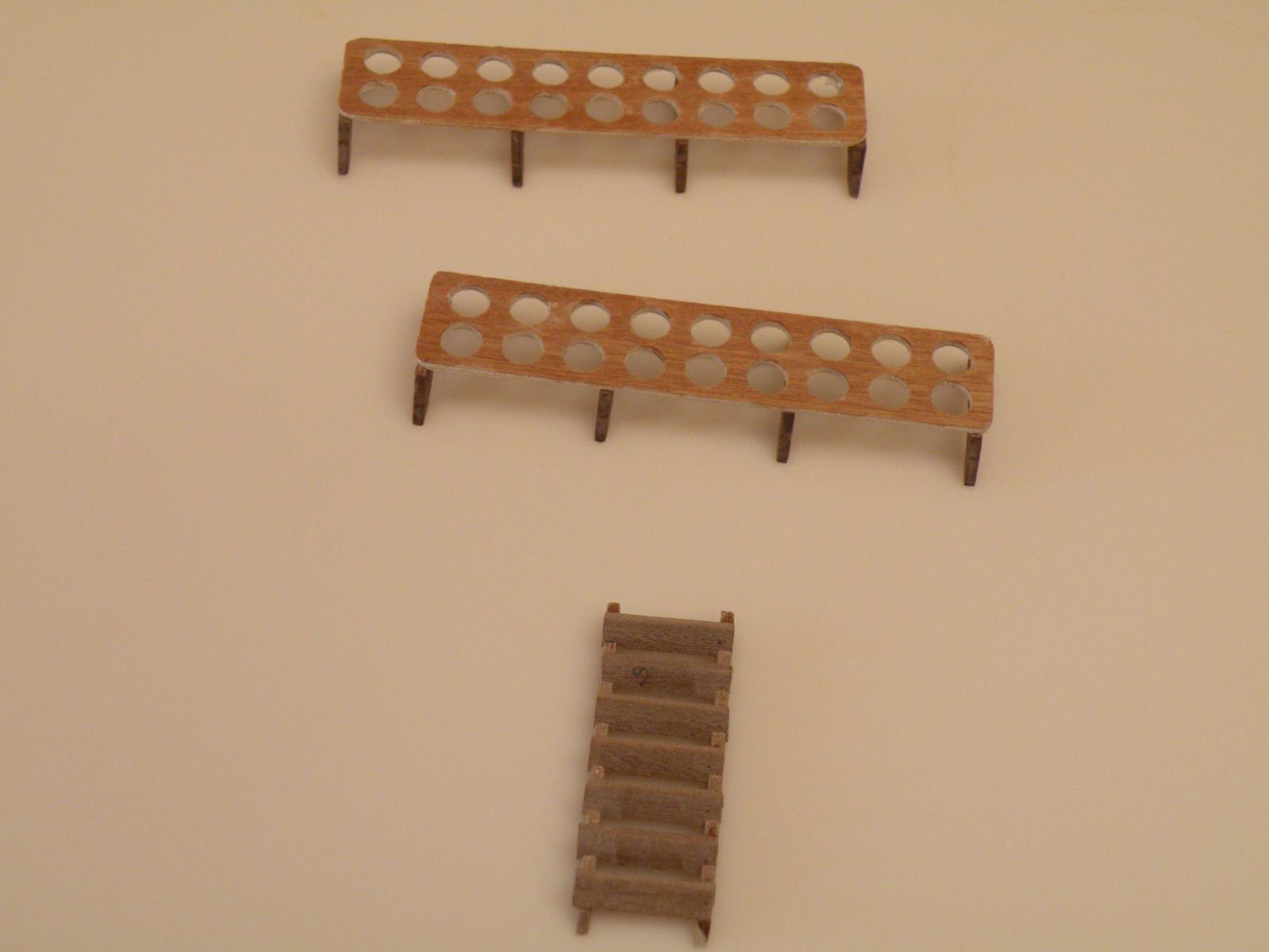
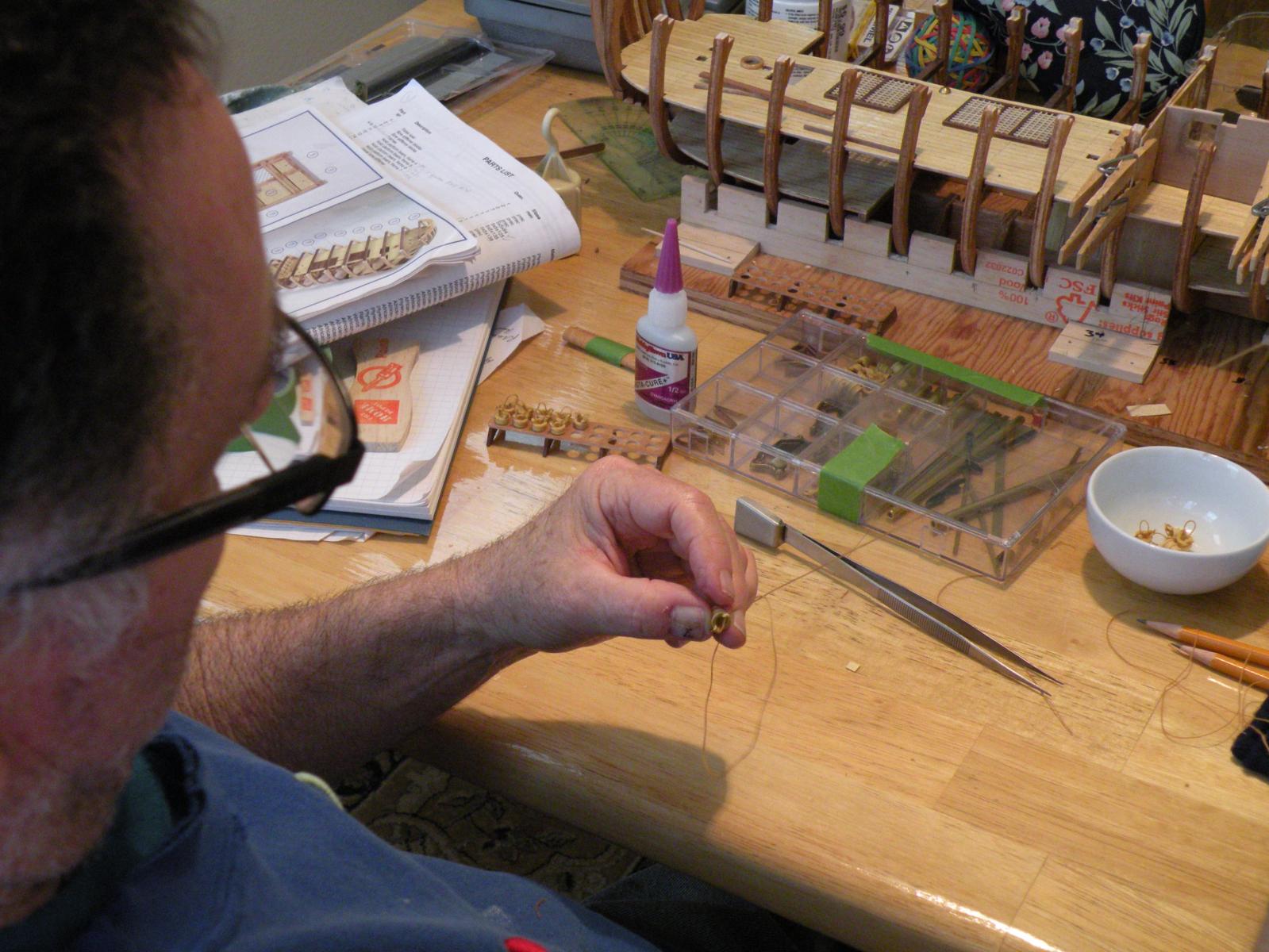
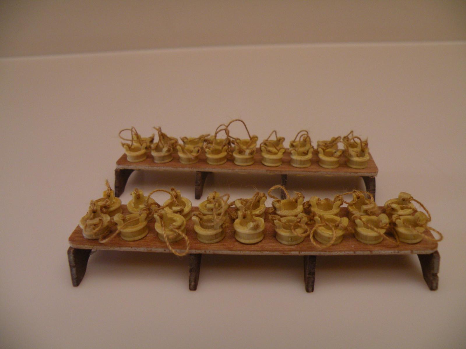
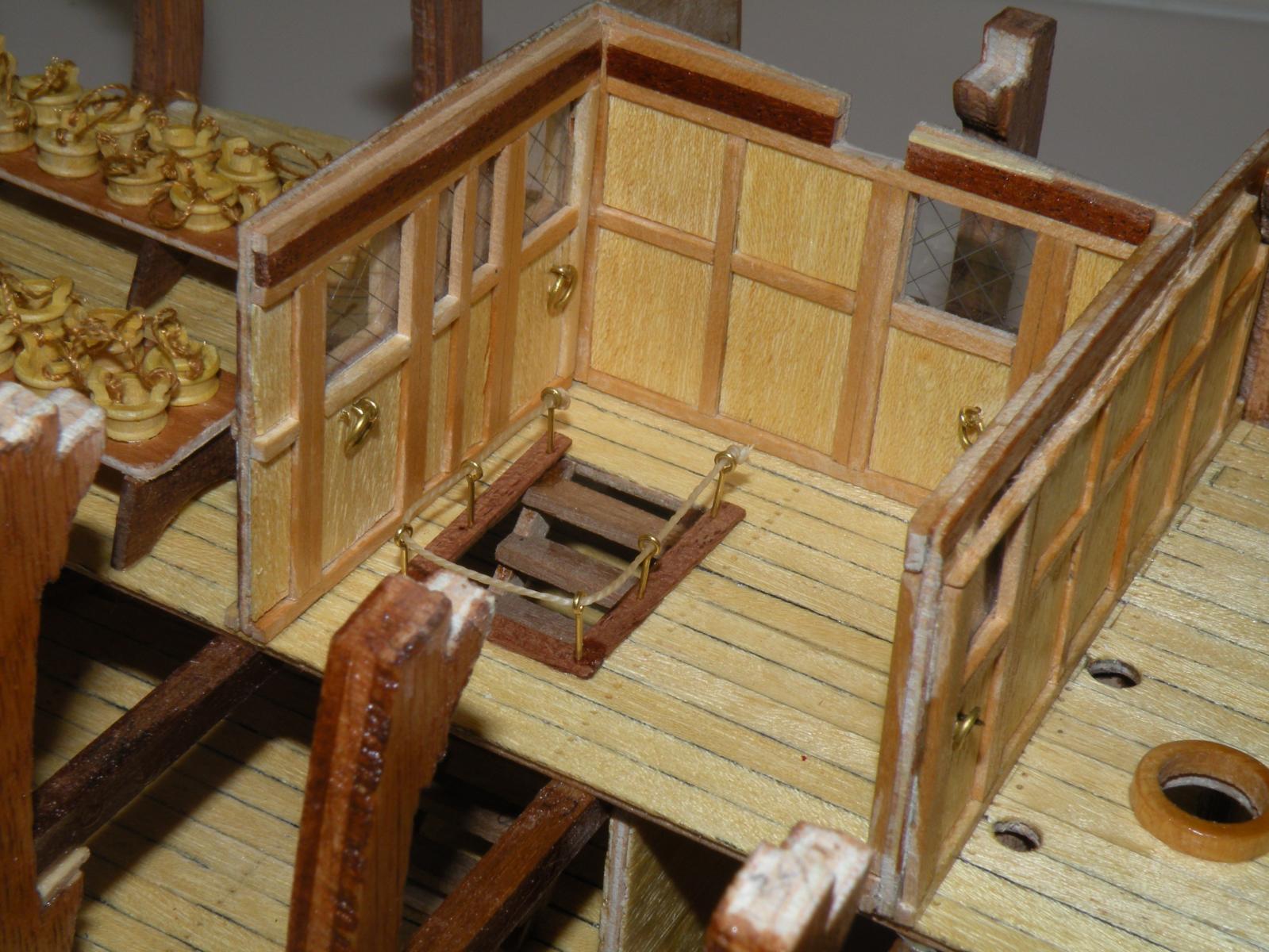
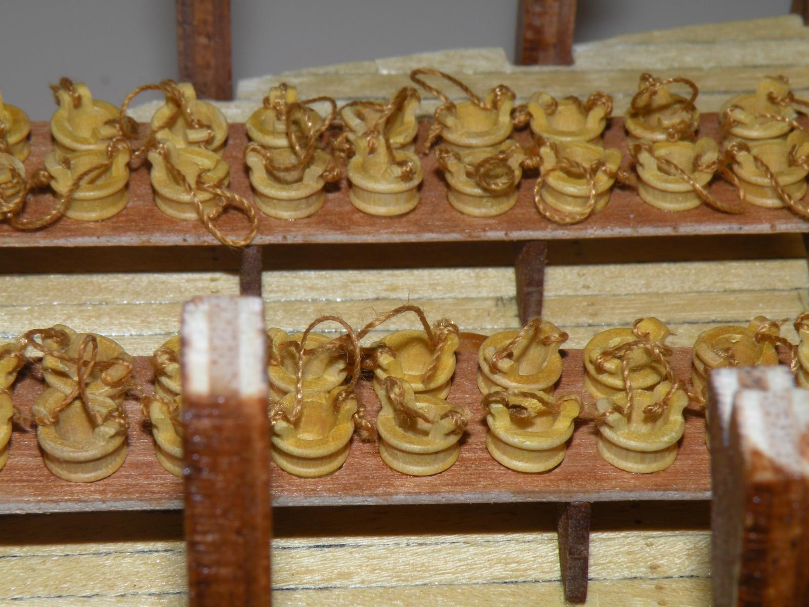
The last major post on my build log saw me complete the lower deck cabin and just start work on the stairway and the breadfruit plants. I was unsure whether to put some greenery into the pots as Cannon Fodder had done. I tried several different ideas and none worked well and all of them were too much work for too little payback. So I opted for the pre Tahiti Bounty. But to give the model a little more umph and authenticity I added rope handles to the buckets. This was a good learning experience in the use of a needle and thread and making tiny knots. My wife taught me everything I now know.
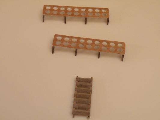
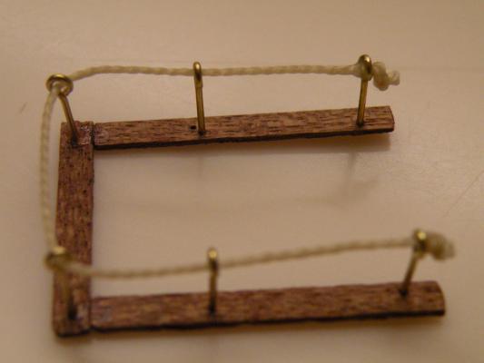
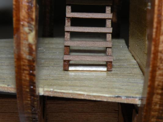
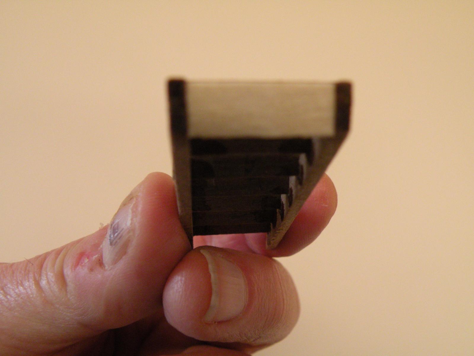
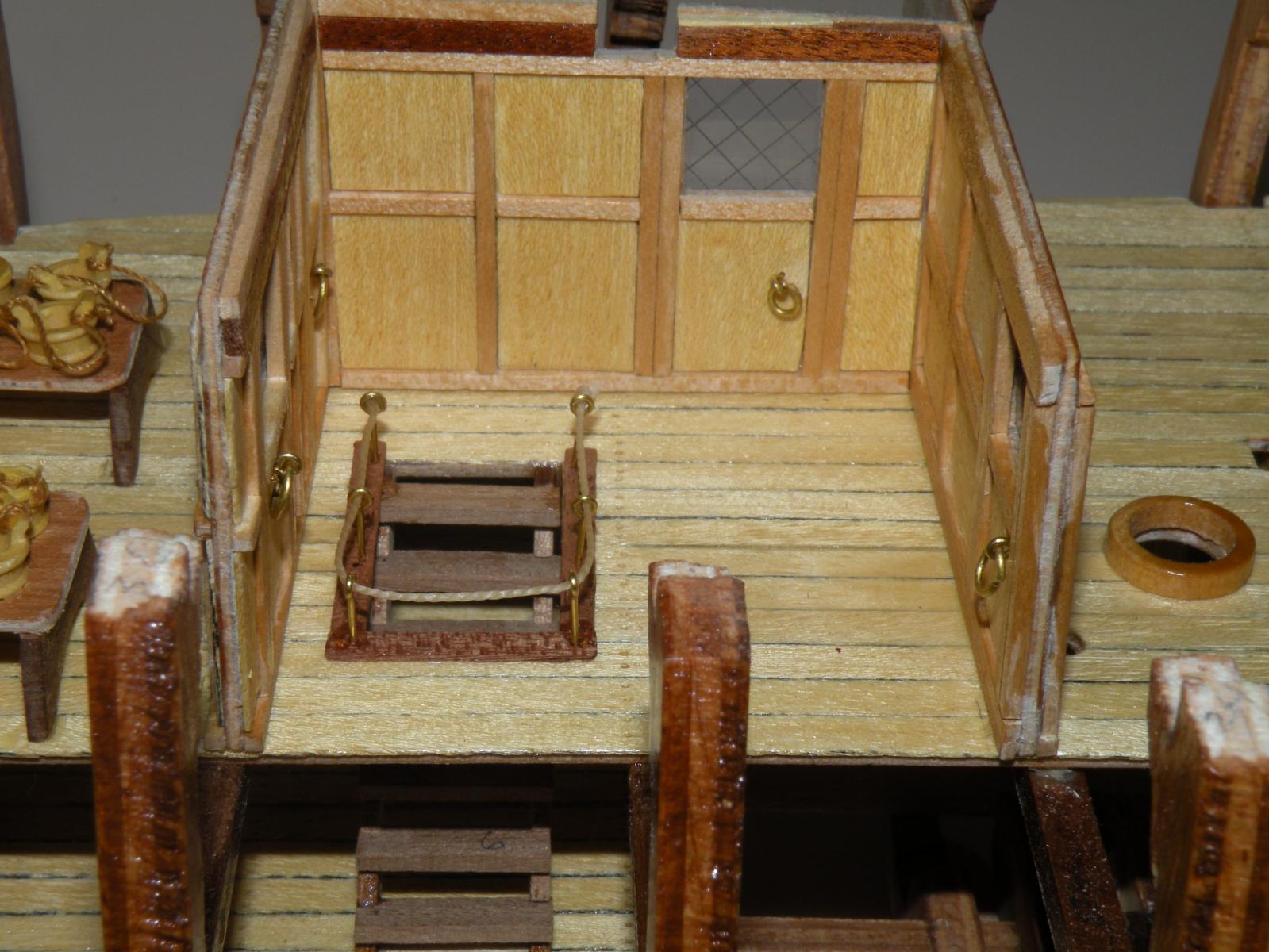
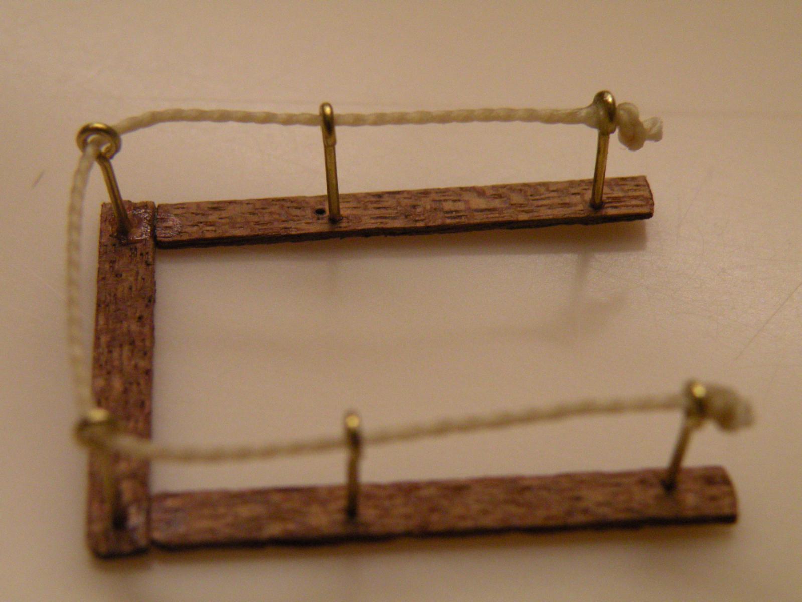
Next I went for the stair way. The only difficulty I encountered here was getting the stringers to pop out of their template. The laser cuts didn't go all the way through. The tips of two out of the ten broke off. I was able to repair one with CA glue but the other was a goner. Into the scrap heap. Thinking I would need to make one of my own, I pondered this until, lo and behold I discovered that only 4 stairs (and therefore 8 stringers) are needed. So I now have an extra stringer. Having built the little stair case I thought that it had very little gluing surface to it, so I added a footer which would glue directly to the deck. Then I thought about building a railing and/or bannister as well cause I thought there was no way the real ship would not have had one. I experimented with different size dowels and square timber for the stanchions but I could not find anything I could build with my current array of drill bits -- either too small or too large. So I opted to use the deadeyes that are supplied. For the rope I found my old sailing ditty bag full of odds and ends of waxed twine and assorted needles. Good find. The result of my work can be found on the following pictures. I still struggle to put captions and text on the pictures, so I resort to all the pictures at the end of the post.


-
Coming right up. Stay tuned for another fifteen minutes or so while I get my photos off the camera.
-
No, they are not. My "picture" isn't totally accurate. They don't end up single file in one lane, they end up shoulder to shoulder in what amounts to maybe two or three lanes. If the lanes are 4 feet wide, then at the start they are taking up 40 feet of the track width. After they've bunched up they take up 10 x the shoulder width of a skinny long distance runner, maybe 2.5 feet x 10 or 25 feet. So just like the fan narrows at the bow, so does the amount of track needed to accommodate these ten runners.
-
This is pretty good CF. I am gaining an understanding of the technique. If you were to draw up your own fan, could you simply start at one end of the paper (say the right side) and divide the width of your paper into equal parts (eg. if the paper is 10 inches, divide it into ten one inch widths. Then go to the left edge of the paper and find the exact center (eg at 5 inches) and mark say one inch above and one inche below the 5 inch point -- basically finding the exact middle two inches of the paper. Then divide that two inches into ten equal parts (ie. 1/5 of an inch each) (here is where metrics work so much better than inches cause you'll never find a ruler using fifths of inches -- but it would work if you start with say sixteen equal divisions instead of the ten)....anyway, back to the drawing. Once you now have equally spaced ten divisions (for want of a better word) on each side of the paper, you connect them with straight lines and you would have your fan. You want to make the left side (the side I said would be 2 inches) at least as small as the amount of space you need to fill at the narrow end of your hull, and the right side, wide end, to be at least as wide as the widest bulkhead amid ship.
I wonder why you even need to transfer back to the bulkheads your spacing lines. In the end you need to have these widths marked on your plank in order to guide your taper. Once the taper is made, the plank should fit in. Do you do this just for visual assurance that it all looks good?
What method has worked well for you in actually doing the taper? I have considered this: I would rig up a vise with very long but rigid jaws. It would be good if the full plank could rest in these jaws. I would insert the plank into the jaws at the same angle as the taper, so that on one end (say the right side of the plank) the whole width of the plank would be inside the jaws, but at the left side (side to be narrower) the amount of plank to be taken off would extend above the jaws. Then I would sand or plain down the plank until it is level/flush with the top edge of the jaws. When removed, it would have the correct taper. Since you are not supposed to taper more than half the width of any plank, and since most planking seems to be 5 mm, that means that 2.5 mm would stick up above the jaws on the left side, and 2.5 mm would be inside the jaws. I think 2.5mm would be enough inside to hold the piece securely, but this is the part of it all I still need to experiment with. Also, heed must be taken to sand or file or plain directly down on the plank. it would seem that any side force could easily snap the plank along its grain. This is my contemplated method. How do you do it?
-
Here's a weird analogy. Picture ten runners running a 1500 meter race. They start in individual lanes and run a couple hundred meters. Then they're allowed to cut into the center lane and they all bunch up there. So now there are 10 runners in one lane (more or less). If you were to trace the path of all of the runners, you would have a tapering into the narrow one lane from the wide ten individual lanes. There's still 10 runners but they are taking up much less space on the track. Weird, I know.
- Eddie and Mike Dowling
-
 2
2
-
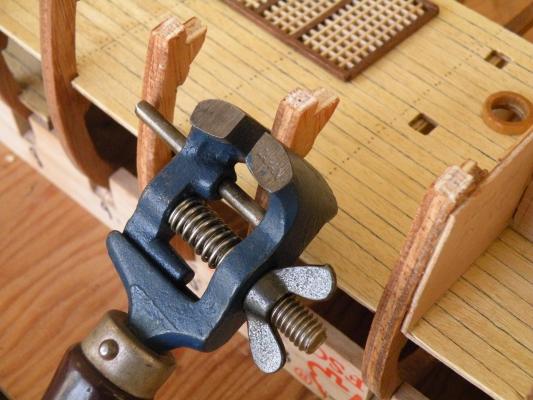
OK, I see how the L brackets are held tight. I have seen someone do something similar with the bolt going through the keel, and I looked at my ship and found places where that would be very doable. But why go through the keel if you can go under it with the same effect. With the brackets being metal and so totally rigid, anywhere you squeeze them together should give a tight and parallel sandwich. Looking at your pictures also made me wonder if I was correct in thinking that my planking was going to be 1x5, so I went and checked. I was wrong. 2x5 it is. Mike, if you're reading this, no need any more to be jealous. Final thought for now, you certainly have a beautiful work space Theo. Do you plan on actually floating your Bounty when its water tight?

-
Theo, you are a god send. Your pictures should be published in the kit's instructions instead of the vague, almost finished ones they provide. By seeing your's I am getting a real good idea of how this whole planking job needs to go. And thanks for clearing up the issue of stairs, 4 or 5. It was making me crazy trying to find that 5th stairway. You noted that the stairs are not very authentic in several ways. I found that true as well and made a couple enhancements to fix the problems. I am planning to do some computer work today and post pictures, but just for the record, what I did was add a footer to give the staircase some decent gluing surface (I am a firm believer in making things stay in place once they are put down), and I added the missing railings cause I wouldn't want anyone to get hurt.
I have two questions....First, it appears that you are holding the model down on the work pad using L brackets and (here's the Q) a bolt through the bottom ends of the keel. Is that right? And second question, are those bungey cords you are using to strap in the planking tight, or just cord with small springs on the ends? Either way does that work pretty well?
Here's a couple pics of my stairs. I guess I shouldn't butt into your log, but I can't help it.


- Mirabell61 and Mike Dowling
-
2
-
CF, that is exactly what I was trying to describe in words -- except this picture carries it to the extreme of a point (making it a triangle). If you cut off the upper few inches you have the trapezoid I referred to and the concept is clear cause you can see the lines distinctly enough to count the "planks" thereby recognizing that there are still the same number of planks on both ends of the drawing, just differing in width. Helpful picture. Thanks for posting it.
-
Can't help you much Mike. Like I said earlier, I'm just beginning to get the concept but if I look at your pictures the first thought I have is "so what's wrong?" Then I look a bit closer and see that at the stem there is less room for planks than back at midship. So I guess that's where the problem lies and why tapering is the solution. But I thought you had said back when that on this first planking you did not care if the planks ran all the way around the hull in one length. So why can't you just plank up to the point where you run out of space, and then end your planks there, filling in the final triangle at the lowest part forward of the hull with shorter, narrower pieces. I mean for a double planked hull, these first layer planks are no more than filler anyway. Your next layer you can plan out precisely and do it the scientific way. This would at least save you from removing six planks. I think removing stuff is tougher than putting them in in the first place. Good luck and have a wonderful B-day. Don't even read this til its over.
-
Whatever you're doing you are doing it well. Very nice work. On my main deck I will try planking over the holes. Seems like it will go faster and if I follow your's and Mike's suggestions I might not ruin the deck. I'm still curious about how many stairwells your kit has Theo. If you can, would you count them and let me know. I don't want to rack my brain trying to find a non-existent 5th stairwell.
-
Measures a bit less than my bounty I think. Mike, have you tried drawing all this out on paper? I find that when I don't quite get it, the visual side of me takes over and I can scratch out something on paper. I've done this with the planking theories and maybe (just maybe) I'm beginning to understand not only why we taper but where. The next thing is how much. Use graph paper if you have some and draw a parallelogram (big words for a geometric dunce like me). Then divide the longest side into equal pieces. I have (conveniently found in my desk) a notebook of graph paper with the squares being exactly 5mm, the size of my planks. (oh, and btw, maybe I'm wrong but I think my planks are 1x5, not 2x5 as Capt. Fisher said earlier his were). Then draw parallel lines from right to left. You will see how you run out of space as you approach the shorter side of the parallelogram. You know, this shape may be a trapezoid, not a parallelogram, cause two of the sides are not parallel. Anyway, you can then divide the shorter side into the same number of planks as the longer side, and you'll know how wide the planks need to be on that side. The difference between the long side and the short side is the amount of taper. Example, long side is 30 inches, short side is 20. Planks are 5 so you can fit 6 in on the long side. But six into 20 is 3.33 inches. 5 minus 3.33 is 1.67. This is the amount of taper needed. You would mark the short side, draw a line and start to whittle it down. Hope all this is correct and helpful.
-
Yes we did decide on either a pre Tahiti or post mutiny ship. I decided on the pre Tahiti since I thought the post mutiny ship wouldn't have any pots at all. In the movie they chucked it all. No use for pots. You should see what I did with my pots. I "sewed" in little rope handles on all 36. My wife gave me lessons in making a French knot and doing this I now can start to dread the rigging in errnest. I'll be posting pics soon.
Given a lot of thought and reading, I can now understand why some calculations re the width of planks may be the best plan. You have the option now to go with the second planking in a different manner. If I'm understanding the whole deal, the full Monty so to speak, it comes down to that if you don't start tapering early on your planks will become narrower and narrower until you have just thin little strips to put into. As they want no planks less than half the width of a full plank, it then behooves you to make some plans in advance.
-
Regarding planking over the holes...I will stay on this log and if need be go to PMs later. I hear what you're saying Mike and I've tried cutting across grain with an exacto in other areas. Even with material that is only .6 mm I can't get it done cleanly. I'm using brand new, out of the box blades and still they don't seem sharp enough to cut cleanly through the fiber. Mine is rawmin. I never heard of this wood and can't find reference to it anywhere. Maybe its just another name for some more common wood. Or maybe just a bad translation.
Are there differing grades of exacto blades? If I do decide to give it a go with the knife, I would first make a paper template of the plywood and then when all the planks have covered over the holes, I'd lay down the template and copy the hole outlines back onto the planks. Is that what you meant by marking where the holes will be?
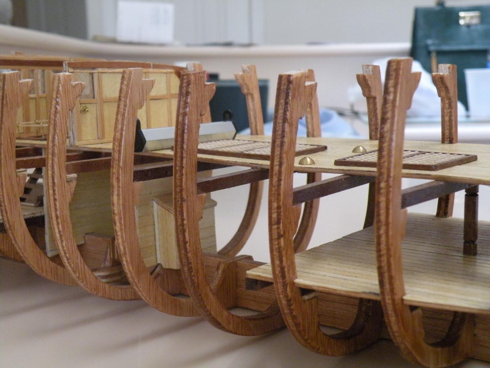


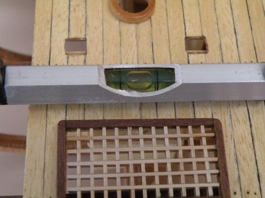
Clamping down the deck to frames
in Modeling tools and Workshop Equipment
Posted
Here is a picture of the two offending deck to frame positions.