


Captain Al
-
Posts
613 -
Joined
-
Last visited
Content Type
Profiles
Forums
Gallery
Events
Posts posted by Captain Al
-
-
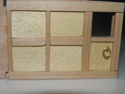
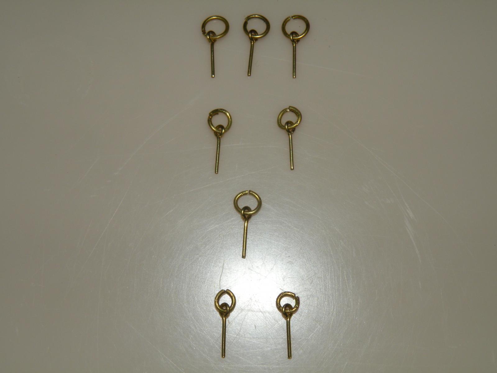
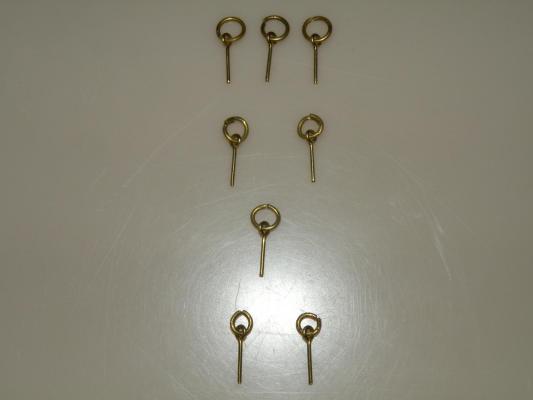 Well I'm in the home stretch of building these cabin bulkheads. I decided to take a break from cutting tiny lengths of 2x2 and rawmin lining and turn to something more challenging. Like putting the door handles (rings) on. The first thing I discovered is that the rings supplied by AL are way to large. At 48:1 scale they would have been 10" in diameter. Even the Bride of Frankenstein didn't have such huge knockers. So I did some work on the 8 or 10 that I'll need to put in and below is the result. The top 3 are as they came in the kit. The next 2 I made a bit smaller by doubling over the wire (like if you were to squeeze them closed too hard). The next one got even smaller by nipping off a bit of the wire using a wire cutter. And finally, the bottom two were made using a Dremel cutoff wheel to take even more of the brass wire. Size wise I like the last 2 best.
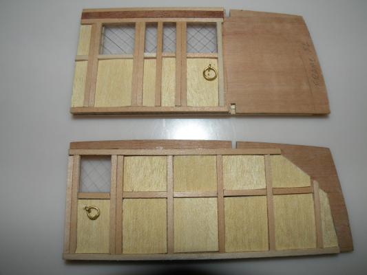
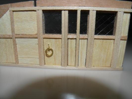
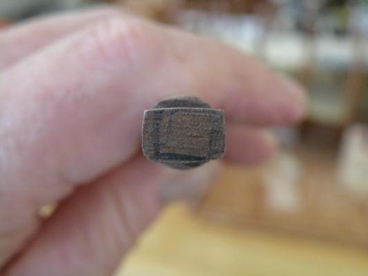
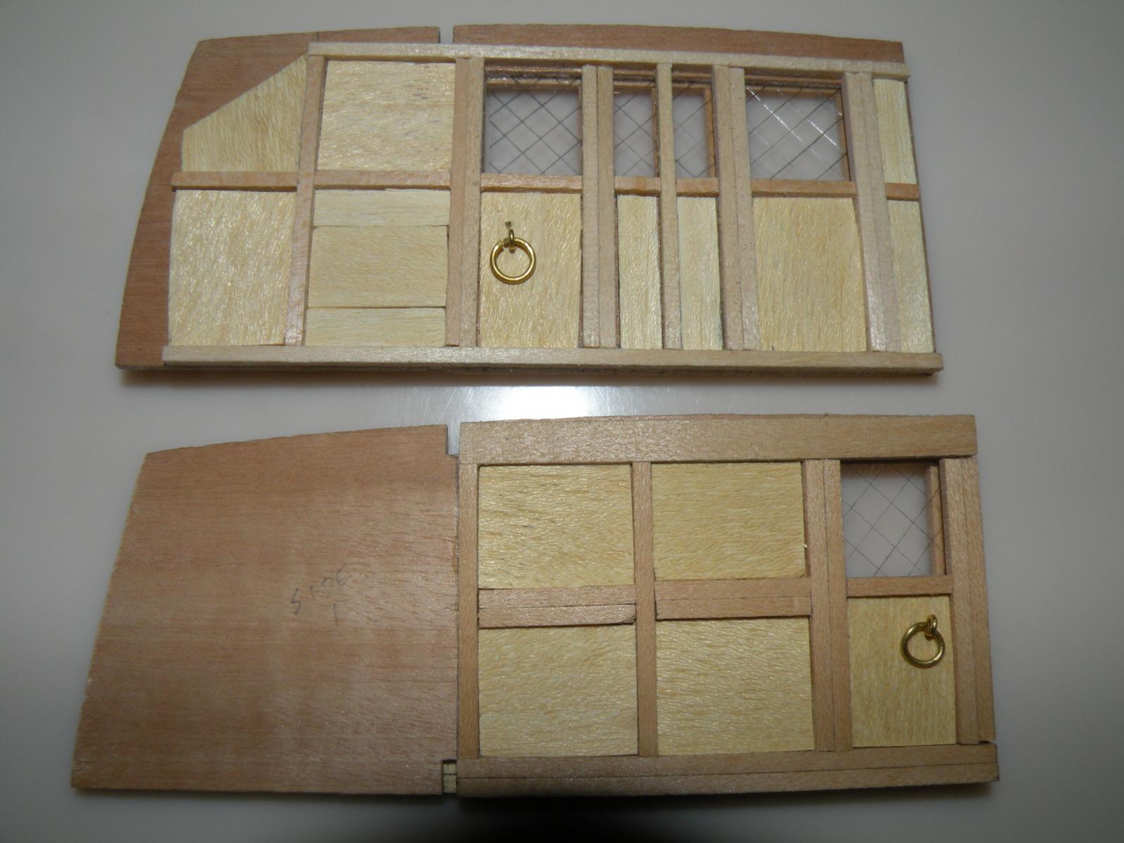
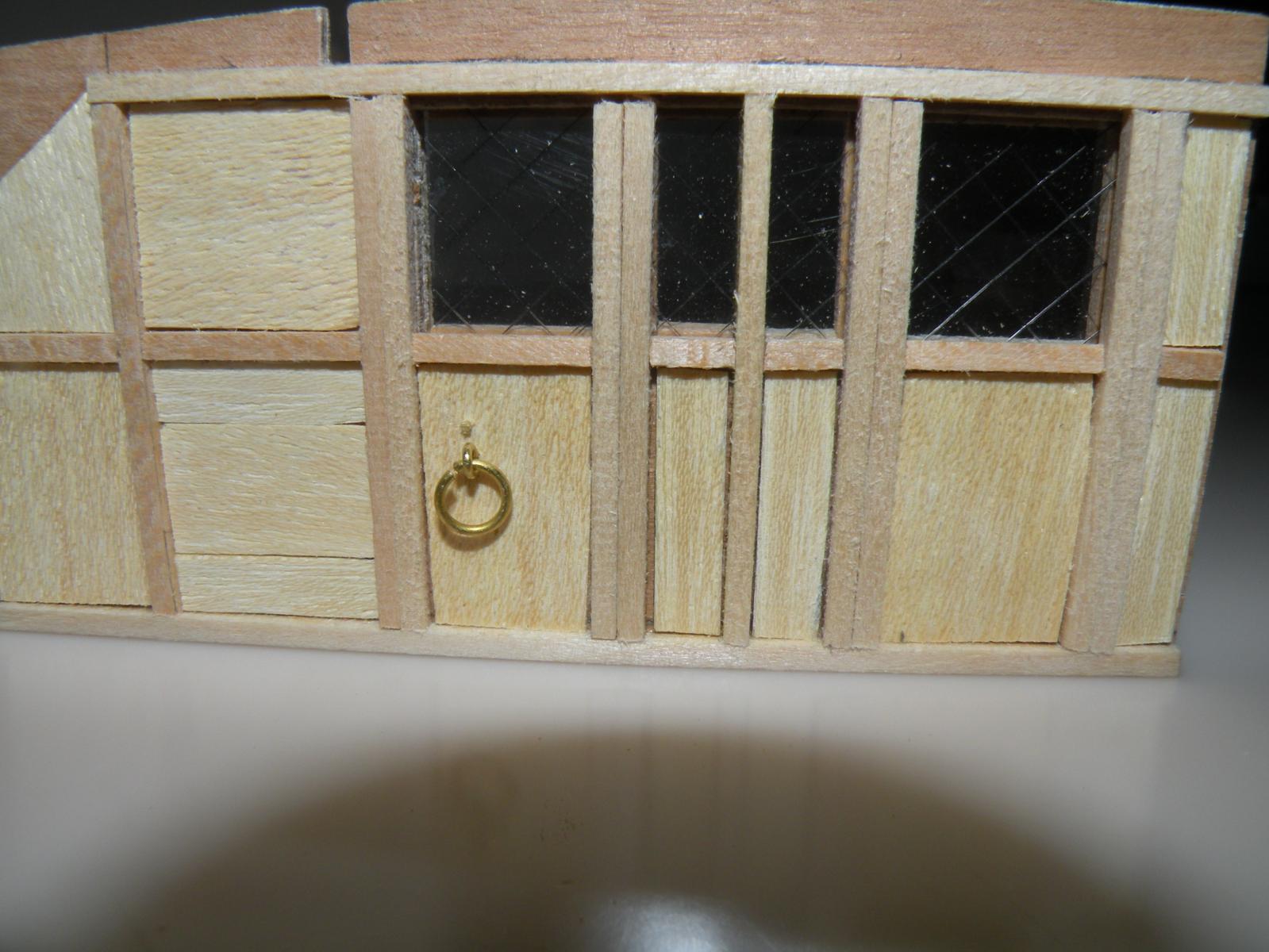
This work wasn't all that difficult. The next step was. I decided to use all the rings even though I like the smallest ones best. So now I had to figure a way to drill holes in the doors which (1) didn't break through to the other side leaving a hole to fill, and (2) didn't exactly run through the hole coming from the other side of the door. AL's pictures showed the rings positioned on the doors on opposite sides (right side on the inside of the cabin and left side of the door on the outside). I decided I'd be rebellious and offset them just a little so that the eyebolts wouldn't run into each other. I tried using my #76 bit but found it was too small; too hard to push the pins through. But my next size is a 70 and I found that too big. No Goldielocks available, so I returned to the 76 bit. By this time I realized there was no way I could stop the drill short of breaking through, and also thought that if I didn't drill it all the way through then I would have to be extremely careful not to push the bolt all the way through since that would shatter the delicate rawmin lining. The pictures will show what I finally ended up with. The rings actually hide the bit of brass eyebolt that I made as fair as I could -- first with the wire cutter and then with a grinding bit in the Dremel.
-
Aliluke, can you put up a picture of a plank nipper? Or describe the tool a bit more. I don't understand how a nipper can be used to bend a plank. I've heard of manual plank benders. I thought a nipper was sort of like a wire clipper, a scissor that could cut angles, that sort of thing. I thought it was used to snip off the tail end of pins and eyebolts that protrude. Or even to clip to size small lengths of say 2 x 2 mm strips. I am about to post on my Bounty log a question about snipping off the ends of eyebolts, so I'll go and do that now.
-
Thanks Dan. Thanks for keeping on site. I hope you're doing well and feeling well.
-
Give it a try Dom. I only have but one window left on this build, but for the future it sounds like a great way to do it. Also thanks DS for the google images search idea. I don't know what forum you could post the .png file to, but it might help lots of other builders.
-
Thanks Mike. I don't know about catching up though. I like the idea of staying in your wake (in auto racing they'd call it slip streaming) and learning from you.
-
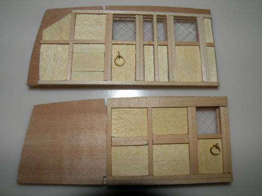
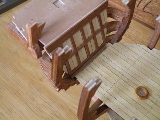
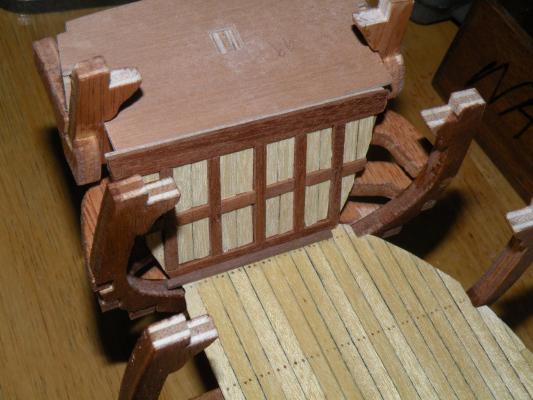
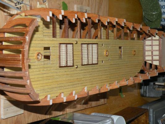
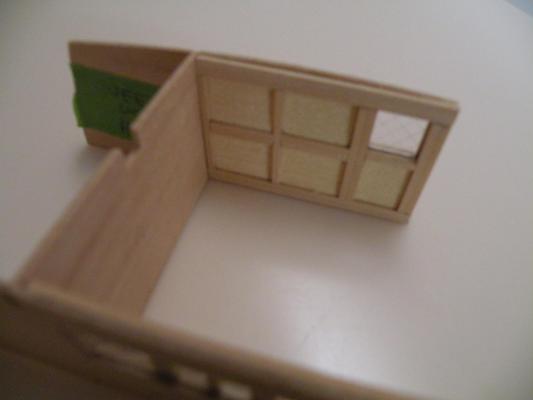
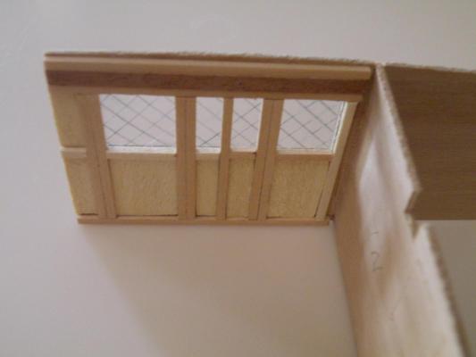
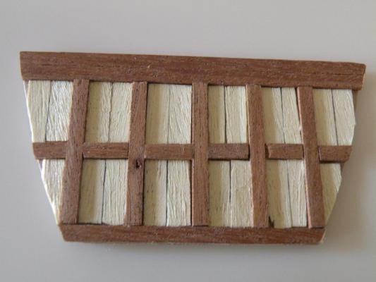
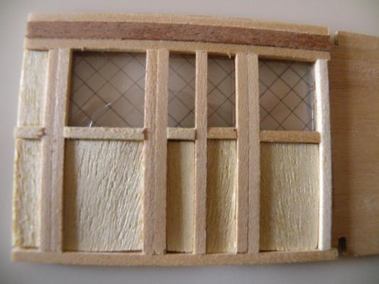
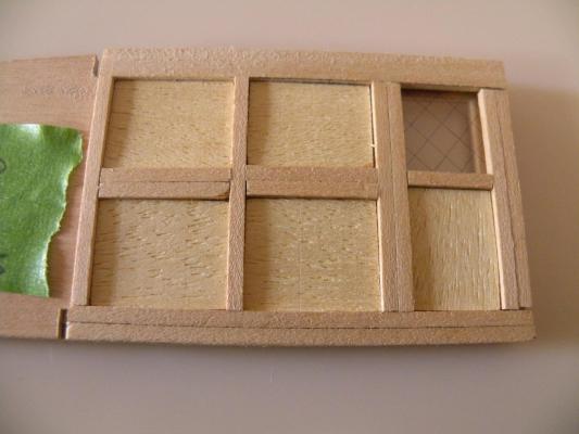
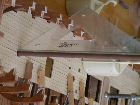
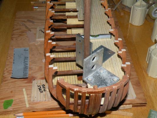
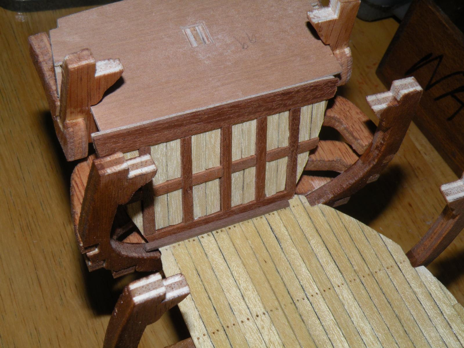
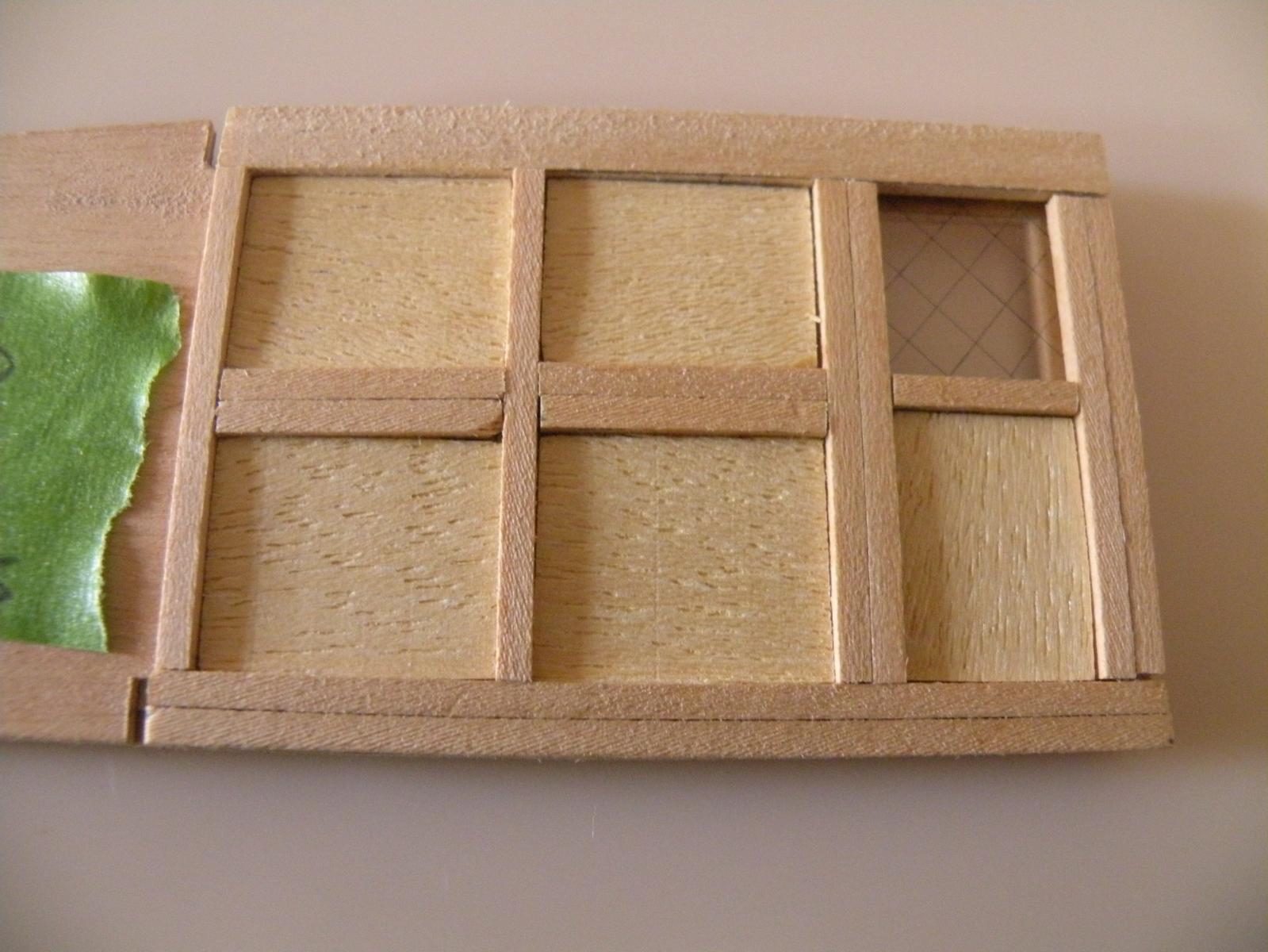
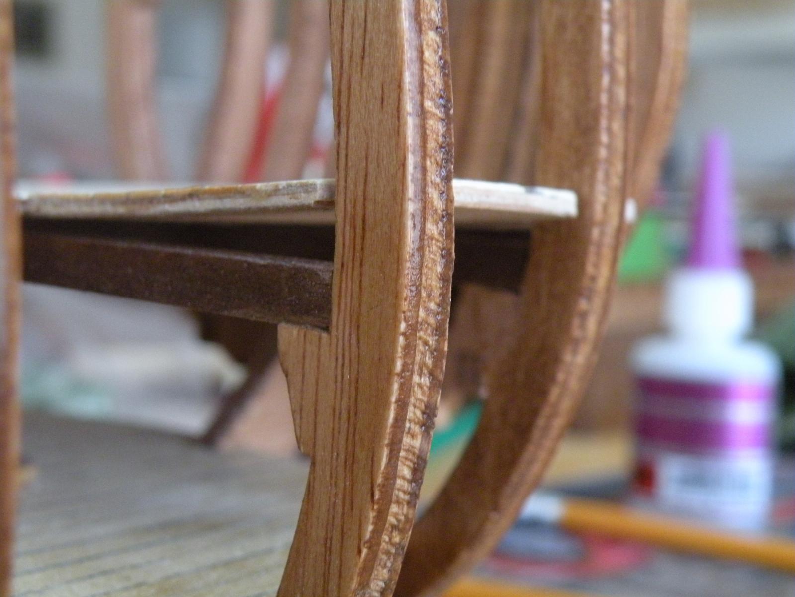
Well here are the long promised pictures and proof that I haven't been shirking my duties. There's not much to add in the way of commentary that I didn't tell you yesterday. I would like your opinion(s) on a couple things. If you look at the pictures of the stern bulkhead (framed in dark walnut) you'll see a strip of 1.5 x 1.5 at its base. I haven't glued any of these parts in yet so I can discard that "footer" if I want. I put it there cause otherwise there isn't much gluing surface to hold this bulkhead in place. Only the narrow upper line at the tip where it meets the ply of the cabin floor above. Do you think this is an intrusion on aesthetics? Its probably unauthentic but that's not my objective. You will also notice in one of the other bulkheads that there is a 4 mm wide strip of mahagony running lengthwise at the top. I was having a hell of a time accurately cutting to 90 degrees the 4 mm spacers that the plans called for -- eight of them to continue the 8 vertical frames. So I finally decided to insert this piece cause it fit so perfectly right out of my scrap heap. Finally, should I sand and varnish the rawmin soffits? The camera sure emphasizes things (like the defect in one of the soffit's lining) that the eye really doesn't pick up.

-
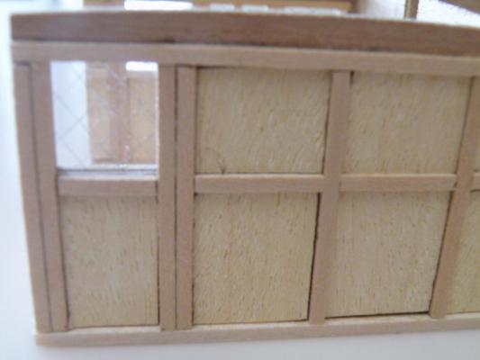
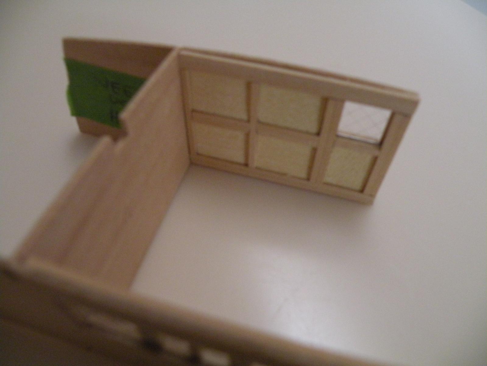
Darn it. Just lost a long (winded) reply to you CF. I'll make it shorter this time. I really like your look better than mine. Shows the cross hatching much more distinctly. I will keep it in mind next batch of windows (I only have one left on this build though). You're also correct re size of real windows on Bounty. At 48:1 scale they would have been 32" x 32" and that would have been a huge fragile pane of glass back then. I thought about dividing those panes in quarters with slivers of wood but decided enough detail was enough. Two questions for you CF, first, how do you make the cross hatch pattern on a computer? What program? I don't have Paint anymore. I was thinking of Excel with grid lines pretty tight and thin. Then after printing on the acetate I would cut the windows out on the diagonal. Second Q: it looks like you followed the pictures precisely when you laid the ramin lining into the soffits, leaving a border of ply showing. I couldn't figure whether the instruction pictures were done that way for illustration, showing that the ramin goes on top of the ply, or if there was a reason for the exposed ply. I took pains to cut out and sand down (and sand down, and sand down) my little squares of ramin so they would just fit into the soffits and expose no ply. That alone has added a couple hours to building these darn structures. I'll post some good pics tonight or tomorrow morning. For now, UCLA is playing Florida in a must win game in a few minutes. Go Bruins!
-
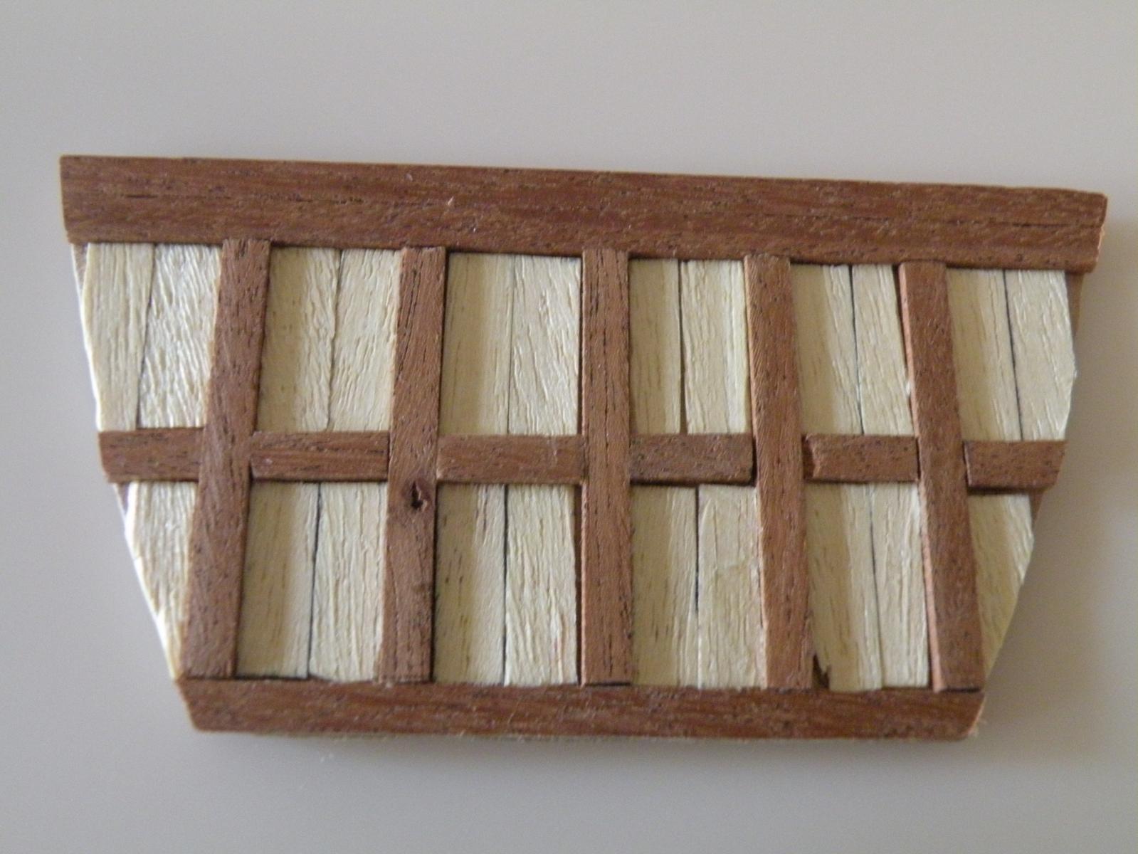
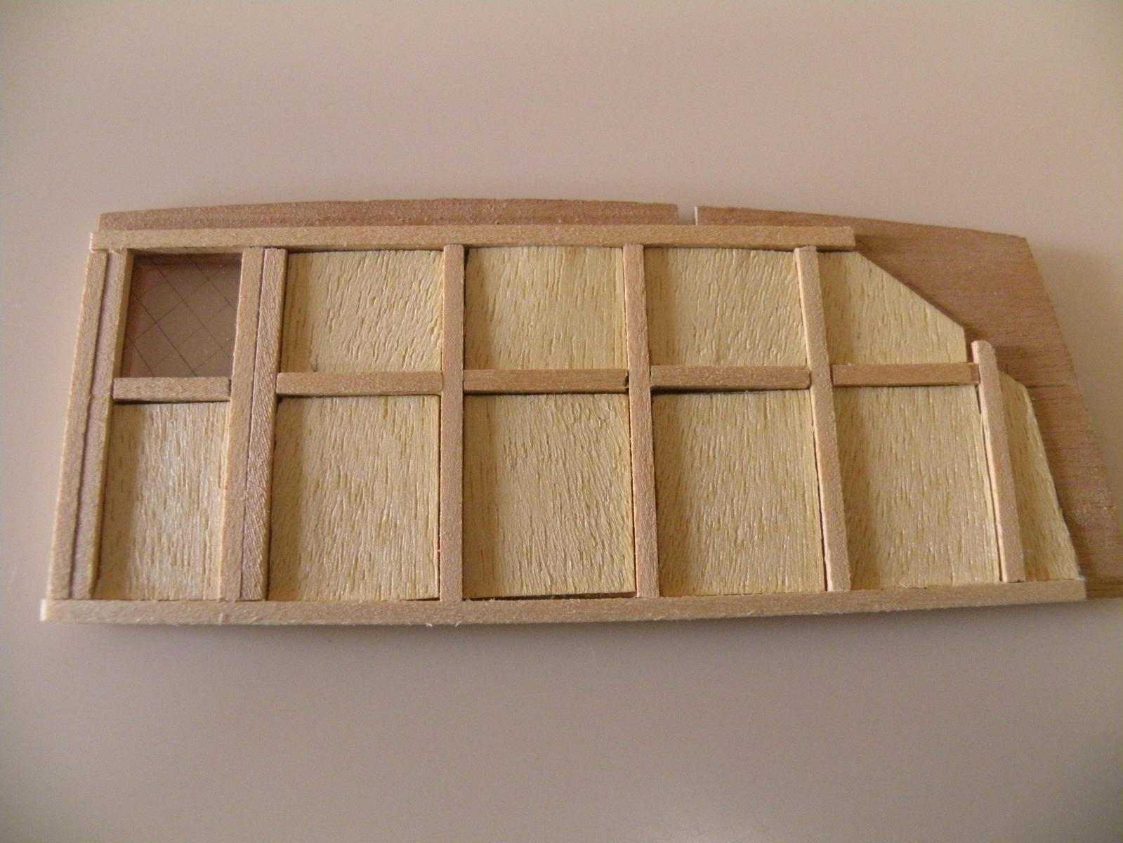
I have been diligently working on the interior cabins, framing in doors and windows. Nothing too mind bending, but some math involved in getting the spacing correct so the windows and doors wind up equal in width. I discovered an interesting problem after I had wracked my brain on it and concluded that my kit's instructions and parts list were once again full of it. It seemed that when I had cut my horizontal frames and laid them out on the ply in between the 7-8 vertical frames, that I kept running out of space. The far end frames were supposed to fit in directly under and over the tips of the long horizontals at the top and bottom. But they kept extending over this point. I made it work by shortening the partial horizontals, which then meant my windows and doors were slightly narrower than they should have been. Figured with the short rations Cpt Bligh allowed, no-one would have trouble getting in and out. It took doing this on 2 of the bulkheads before it dawned on me that the size of the wood I was using was not the 1.5 x 1.5 the plans called for, but more like 2 x 2. When this half mm was multiplied x 8 vertical frames it meant 4 mm more space was required. If my wood is 2 x 2, then they gave me no 1.5s cause mine is the smallest in the kit. So there. The other thing that's been biding my time is the windows and how to cross hatch the acetate. I took Mike's suggestion and went and got a wet erase marker. After scoring the acetate I rubbed this ink into the grooves and wiped off the excess. Not totally satisfactory; not visible as much as I'd like, but still its OK. I will post some pics soon of the work I've done to date.
-
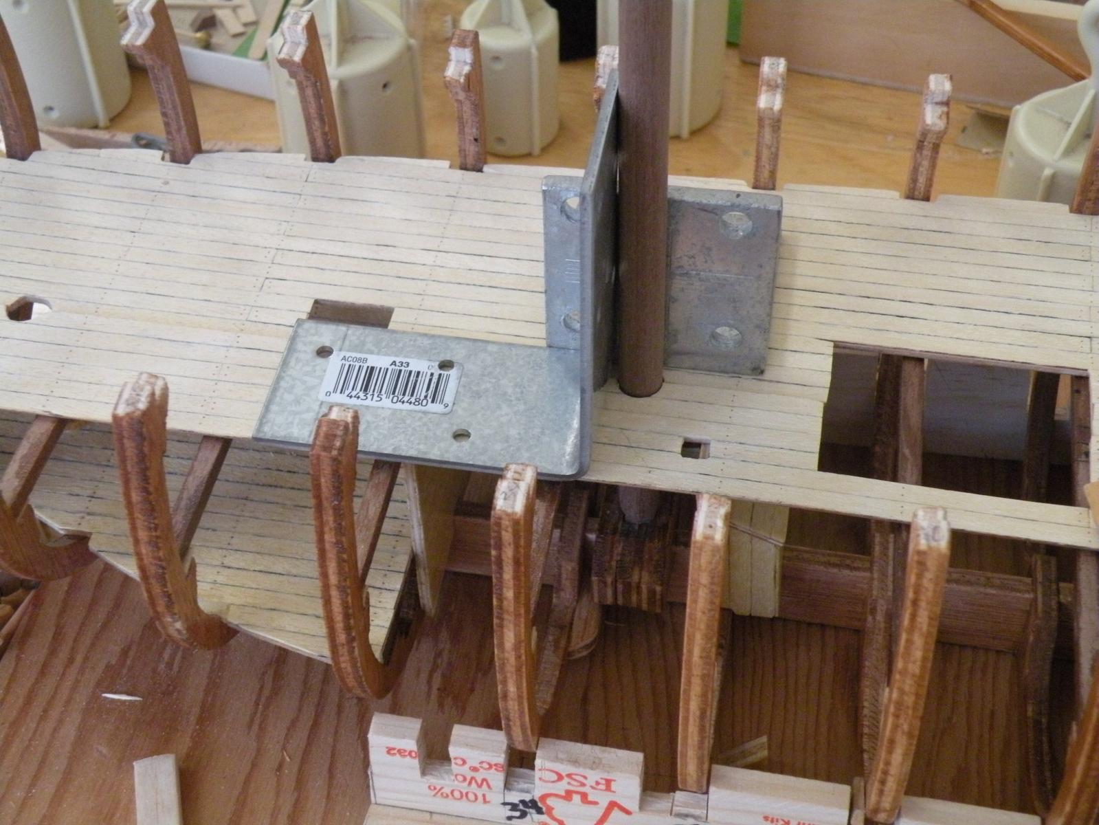
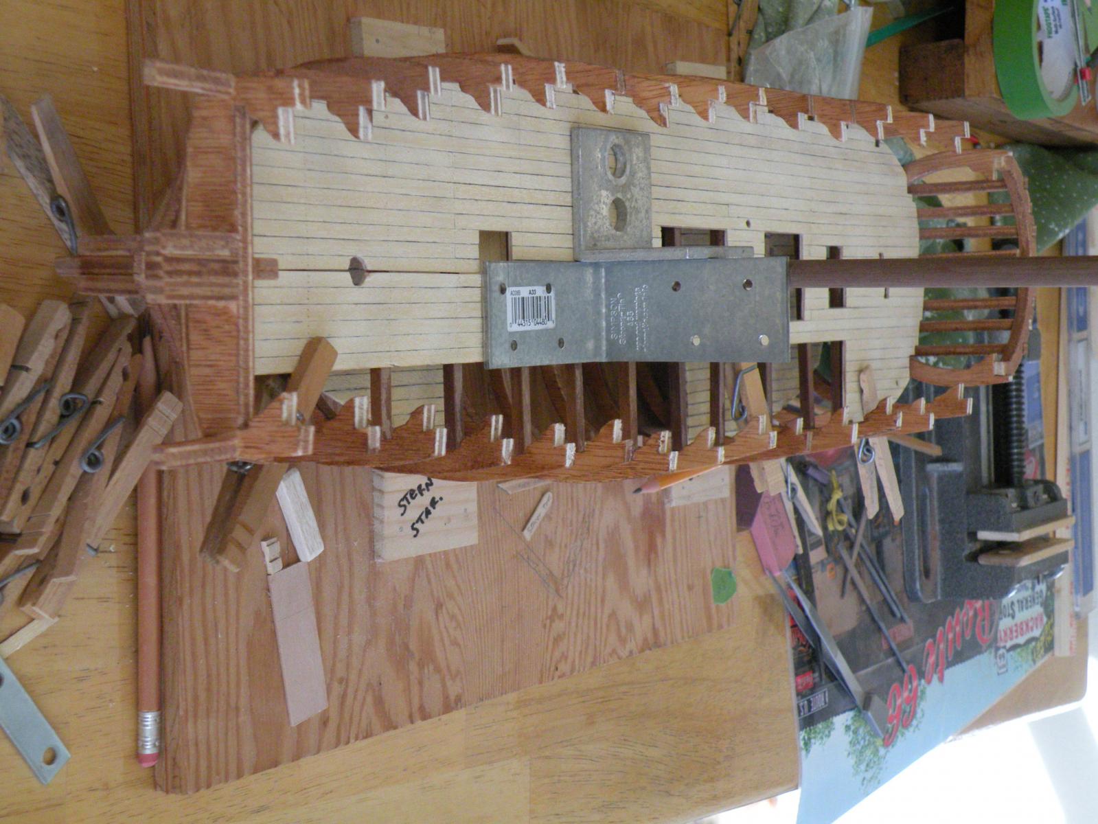
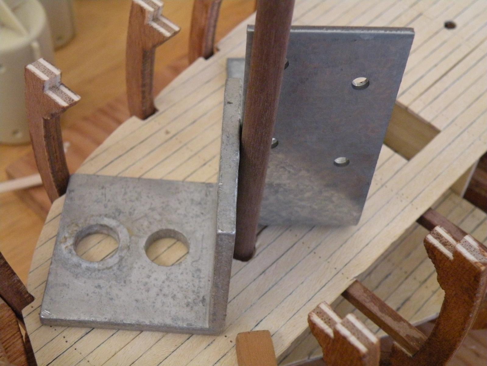
Dom, I'm not on sabbatical, just tied to my work table. More on that later, but to answer your question re mounting bolts if I can.... if I understand you right you want to countersink the head of the bolts into the keel and leave the shank/threads extending, so you can then fit these bolts down into the brass mount. I can only visualize two issues. (1) countersinking the bolts in the keel obviously requires drilling holes into the keel. So I wonder how wide is the keel and what size are the heads of the bolts? If there is plenty of space to drill or bore these countersink holes, then its only a question of how deep and if you really want to do it right and have a flat bottom hole. In all the woodworking I have done (not really that much, but enough), I have never gone out and bought the right bits for countersinking. You use what is called (here in the States) a Forstner bit and it drills out a flat bottom hole. I normally just take a bit with a slightly larger diameter as the head of the screw or bolt I'm countersinking and leave it at that. (2) you'll probably want to use some epoxy in the countersink to hold the bolt firm. Otherwise it doesn't seem like a pain to me. But I wonder if I even am seeing what you're going to do correctly. If I do, then I also wonder if the model can just sit on brass rods that extend into the keel. Again, same issue, how wide is the keel?
-
I've been looking at your pictures and I guess what is happening is that you did the "easy" ones and now are going at the bendy ones. The work on the first few look great. I'm impressed. If I get that far and it looks that good I might quit while I'm ahead. What's the difference between a half open hull and an 80% open hull? I'm surprised your strakes are 2mm. Mine are only 1mm. That is a big difference which will make my bending much easier. Still I think I will get some type of tool or use a soldering iron or my wife's hair curling set. Will your second planking also be 2 mm? That'll be one solid hull -- compared to mine it'll be like a man o war. You haven't mentioned or shown the use of pins or clamps to hold the wet planks in place while they dry. Recalling many of the posts here on planking, if I'm not mistaken almost all are using clamps (a lot are using the modified paper clamps). I may be wrong that they are using them to hold on wet wood before gluing. Maybe they are used only when the planks are being glued on. But I don't see why clamping wouldn't be good in both processes.
- Eddie and Larry Cowden
-
 2
2
-
Like Dom said, and I didn't know this, if your build is double planked, then your problem isn't til later. Mine is single planked so its got to be good on the first pass. I haven't yet figured out a fall back position to when I screw it up big time, but one thing I'm considering is copper plating below the water line. I'm also wondering what adjustments to various other parts of the ship would have to be made in order for me to double plank. Seems I'd be one layer of planking too thick for the bulwarks but otherwise can't think of a major issue.
-
Mike, the tool I was referring to may just be a lamp. Its the black cord and little box at the bow end. I suppose the difference in our kits and Dom's regarding the anchor rode is that ours is open hull and therefore you can run the rode all the way down through the decks. Closed hull you gotta coil on deck.
What are you doing about the bright shiny finish of all these brass fittings? Are you making an attempt to age them or make them look like iron (using blackening stuff)? I'm still up in the air. May just install everything (maybe not the cannons) bright and shiny and let age weather the brass naturally. I should live long enough to see them with a nice patina.
-
Dom, I looked carefully at the pictures and here's what I can make of them (re the hawse pipes)....the anchor rode (be it all chain or chain and rope) runs through the hawse pipes in the bulwarks to the windlass. The excess then runs down through the main and lower decks and is coiled in the bilge between the forward and aft holding platforms. Two things seem curious to me in this. One, I can't see the hawse pipes for the main deck (not the bulwark pipes, but the pipes for the excess to run through) and I can't locate a part for them in the parts list. Two, I would find it strange to stow anchor rode in the bilge. Yet this is what the picture on the box shows pretty clearly. More on this I guess when I get there. Right now I'm just going to stick parts 93 ("anchor hawse pipes") in their designated holes in the lower deck.
- Larry Cowden and Eddie
-
2
-
-
-
Well I guess I'll have to interpret "progressive offset" any way that looks logical. Usually that takes me a couple days of looking at pictures, plans and trying to dry fit the next in line parts. Nice pictures of your interior Mike. What is the little electric tool over on the side? Maybe you or Fifthace can answer this re bending the planks. Many posts and articles discuss the technique of soaking the planks (sometimes as much as overnight) and then using heat (soldering iron, bending iron, clothes iron, all sorts of heat producing tools), bend the plank gradually into shape. What I don't get is how to know what that shape is unless you either have built a replica of the framing itself (a jig more or less), or you bend the plank right on the model itself. And then, where to you let this plank dry? You can't glue it on until it is dry. I can come up with only one technique that takes all this into account; please tell me if I'm on the right track: You soak the wood til its very bendable. Then you bend it onto the frame wet, using the heat to encourage the bending. You pin it in place and let it dry. Then you remove the plank and start again, this time applying glue and pinning and clamping as you proceed. Then you wait til that glue dries and do another plank.
Dom, thanks for the facts about the hawse pipes (and other metal fittings). I thought they would have been bronze (not brass of course) and would acquire a greenish patina. You're saying they were iron and turned black. I hear what you're saying regarding the hawse pipes being in the bulwark. I think they will be as well. I just haven't reached that point. But where the chain comes out of the deck they come from these two little brass button like fittings with the insey bitsey hole in them.
- Eddie and Larry Cowden
-
2
-
Thank you. I was going to use it to glue in my brass hawse pipes. I will go get some CA gel or epoxy instead. I'll need it anyway for lots of other ornaments. I have what is called "gap filling" CA, but its still pretty runny, and dries in 5-15 seconds. Is this the gel or is there stuff that is actually called CA Gel?
As long as I have someone on the line, and speaking of brass, maybe another quick question -- is there some household product that will "weather" those shiny new brass hawse pipes and make them look more like weathered bronze? I'd like to do that before I glue them in.
-
No-one has mentioned the use of PVA or carpenters glue. Is that cause it is no good for metal to wood?
-
It goes without saying Mike that now I'm hating you. You're making great progress. The filler looks nice and like fifthace said, it should help a lot. You've got all your decks laid and even had time for a launch. I barely have time for a lunch. This morning I finished sanding the lower deck and putting a second coat of urethane on it. That's that for this deck. I'm working on the stern structure. I have 3 questions for you...
1. You mentioned that you broke a piece a couple times. Was it the wood for the bow bulwark? Did you have to make that piece from one long strip and bend it to fit? Mine comes in two pre cut pieces that butt up at the front. My real question on this is: my instructions and pictures note to "leave a progressive offset." I don't know if this means overlap the end of the deck or leave a bit of deck showing (for some purpose later, perhaps stanchions). Did you have to deal with this progressive offset?
2. Your filler I know is balsa. What size did you use? Did you fill the cavity entirely, and did you use some scientific method (as described for example in one of the planking articles) to measure and cut the layers to size so they'd fit in there snugly? I've been thinking about filler but can't get my head around the techniques of doing it. Thought maybe there is a simple way of gluing in material, then just sanding the protruding amount to the hull shape.
3. I forget what the third Q is, but here's one. I still have no answer to if the hawse pipes should remain shiny brass or get weathered somehow to look like bronze with a patina. Would soaking in vinegar do anything?
Keep up the good work. I'll post some progress soon. Seems I have more questions than answers.
- Larry Cowden and Eddie
-
2
-
Well I'm glad I used the carpenters glue even before I posted the question. I never use the CA over a large area such as all the beams and decking. Just too afraid of having it run and get on my fingers. I really like painting on the white glue and I do thin it somewhat with an eye dropper for control. I was asking what really was a moot point since I'd already done it, but I did not know the answer. I'm glad everyone including Dan supports using carpenters in such situations. Its been on there now a full day with clamps, so I think I'll take off the clamps and see how she is.
As for the gaps between decking and frames....I didn't think that was inherent to open hull planked models. I thought it was due to my ineptitude in installing the frames, or because the cutting of the deck ply was just not very good. I filled most of them on the holding deck and will probably do the same on this lower deck, since I have to fill a very narrow space between the two halves of deck over about 3 inches aft of the main mast.
Thanks for your compliments. Slow and steady can get it done.
-
I'm now waiting for the glue to dry on the second half of the lower deck. Tomorrow I will add the adornments (mast hole rings, grates and hawse pipes, then give the deck 2 coats of verathane. I would like to make those hawse pipes a little less shiny and bright than they are. The real ones I'm sure were bronze, and they would have developed a green patina to them. Any suggestions on how to "age" these little brass pipes?
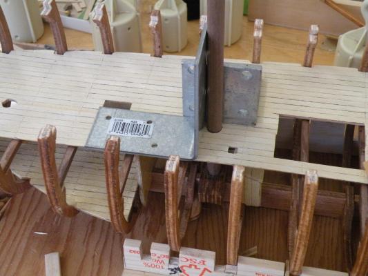
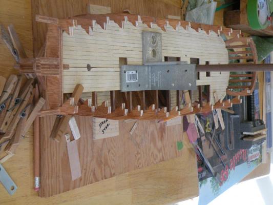
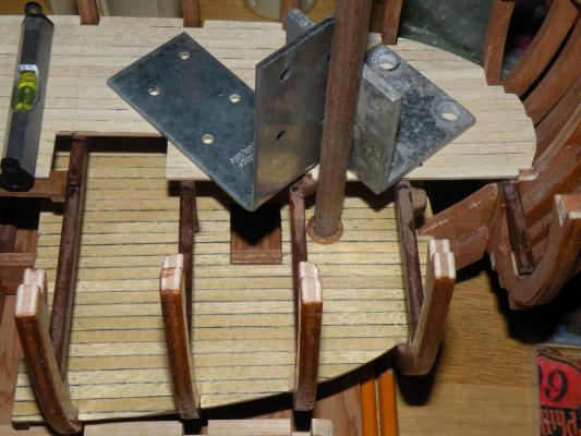
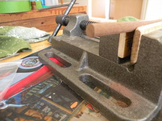
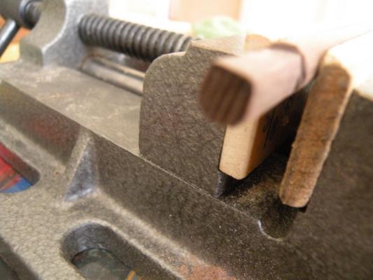
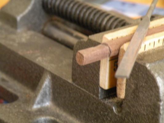
One more picture I couldn't resist showing. Here is the warp that has been my Achilles heel for a couple weeks. As I speak it is being clamped down and weighted down and I hope to H the glue is strong. BTW, which is actually stronger, CA or carpenters glue? Anyway, tomorrow I will see.

-
Well, it seems like I am getting both thumbnails and large photos into the post, so I am doing something wrong. I am going to resort to the simpler technique and attach the pics at the end of each section.
To make a long story short, I am satisfied that I have the masts running well down to the keel and into the mast steps. The moral of the story is still the same: don't do anything further until the frames are perfect and don't try to work with a warped deck. I believe all the of the misalignment of these mast holes (and they really weren't horrendously bad, just not perfect) was due to the adjustments I had to make to the first half of the lower deck to get that deck to lay down onto the beams. Many rebates had to be enlarged (probably to square with misaligned frames) and that in itself would be enough to throw it out of alignment. But I'm happy to say that all the fixes went well and I didn't break anything further and didn't ever lose my patience or temper (as I used to when I modeled at 12 years old).

-
Updating my log. It seems like forever. I guess I'd rather be modeling than taking pictures and working on a computer.
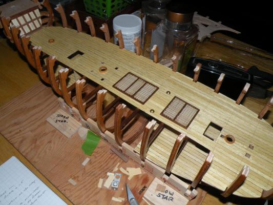
From the looks of the pictures I last posted I had completed building the grates for the lower deck and thought I could get that deck in place in a day or two. Not. My old nemesis warpage came to haunt me and halt progress for more than a week. I've complained about this before but now I really see the consequences. I tried several times to flatten the false deck but couldn't. So I decided just to plank it and install it and trust in glue to hold it down.
Taking Dan's advice I decided not to stain the deck and to varnish (urethane) it after it was installed. I dry fit it and all seemed OK. So I went ahead and glued her down using Elmers on the beams and the underside of the false deck where it would meet the beams. I've always glued both parts when using white or yellow carpenters glue. Maybe with these pieces being so small that isn't necessary, but I do it anyway. Because of the warp here and there and because of all the cut outs for grates etc., I needed to us many many clamps and weights to get it sitting tight to the beams.

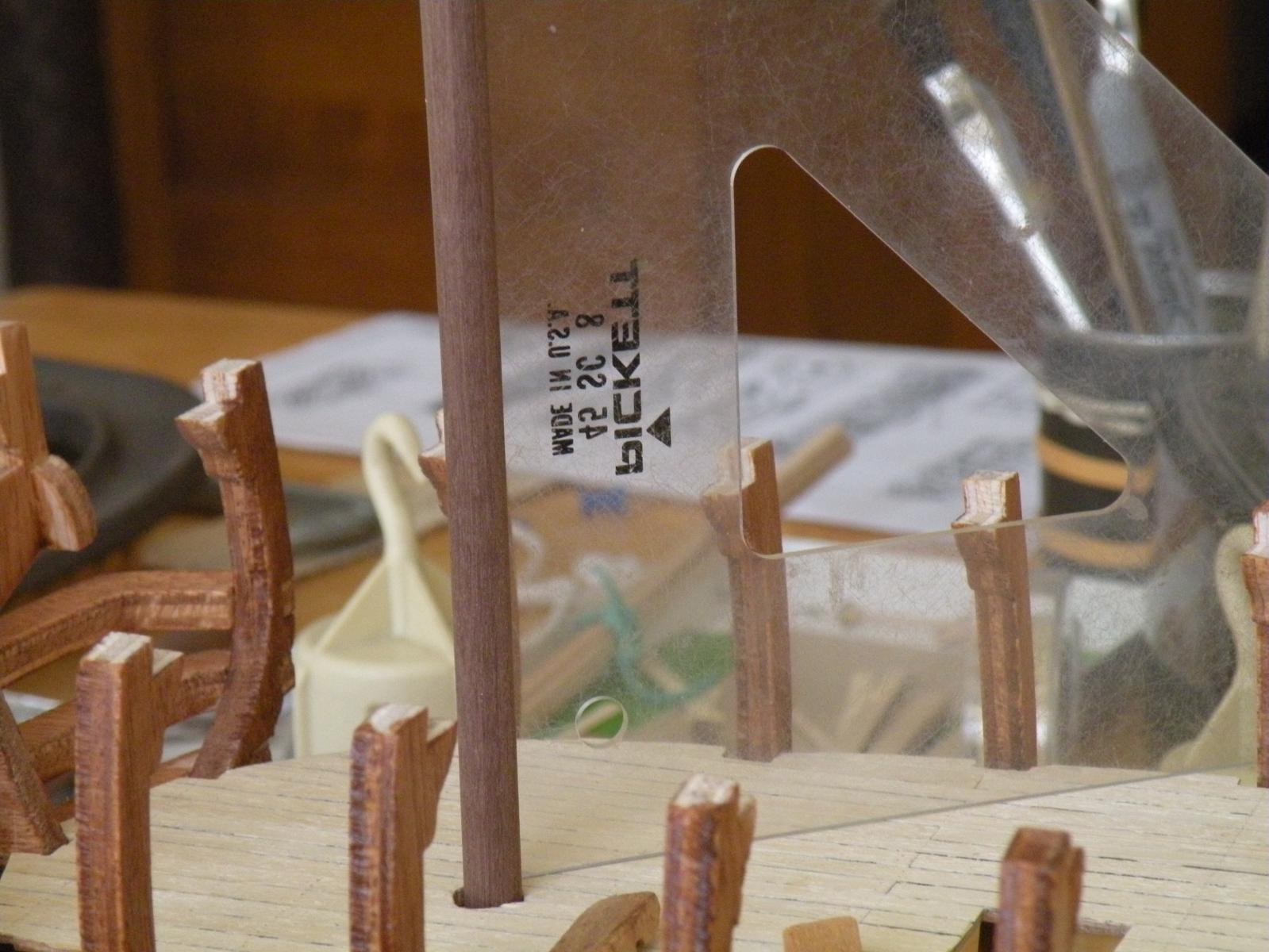
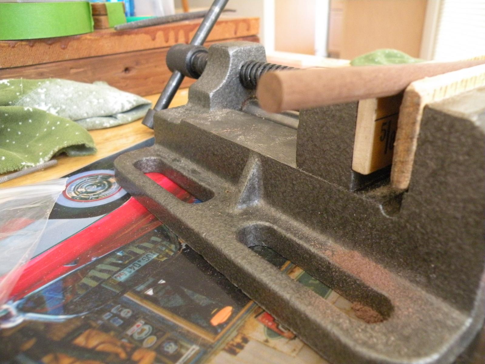
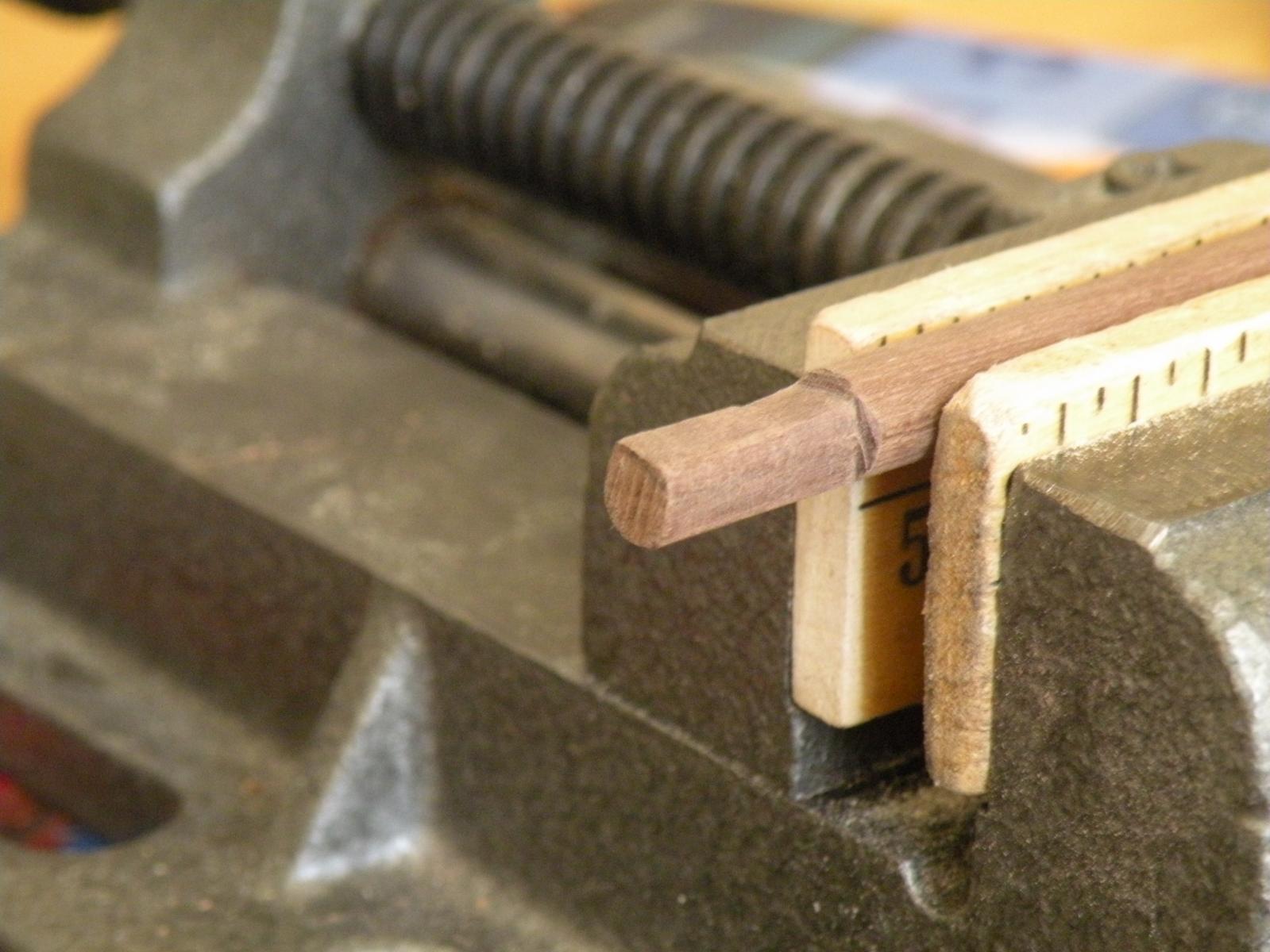
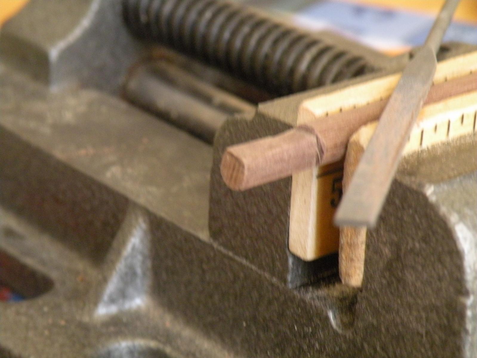
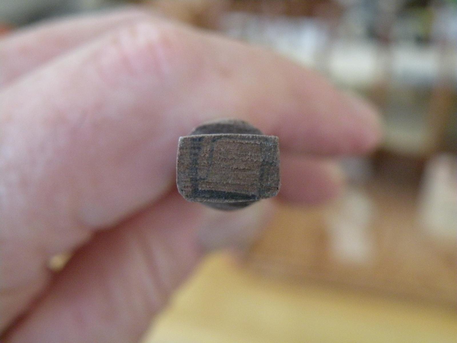
Coming back the next day I was ready to glue in the second half of the deck. Both halves had fit well earlier when dry fitted, so I thought I was home free. But thankfully I did not jump right in and glue it down. First I thought I would check the masts to make sure they ran straight down through the openings and into the mast steps. When I placed the 3 dowels into the holes I was dismayed. First the mizzen and main did not run down squarely on top of the step, and second, the foremast would not even slide through the opening on the holding platform. I was in for some interesting work. To begin with I needed to do right away what I thought I would be doing many months from now -- that is cutting tenons into the lower 10 mm of the masts so they would fit into the rectangular openings in the mast steps.

I hope I'm adding these photos correctly.
Well this work went reasonably well. I used several different files after finding that my Dremel didn't have an attachment that would work. I thought about cutting and chiseling as I'd have done with large scale woodworking, but I didn't even try that. So after cutting these tenons, I found that the masts sat pretty well and almost perpendicular. I needed to ream out the holes on the top deck just a bit to lean the mast in the direction I needed to. Later on Dominic would remind me that Bounty's main and mizzen have a slight rake to them. Going back to the plans a second time (I had checked this out earlier and found no rake) I found Dom was correct re the mizzen (4 degrees to the best of my measurement) but not so on the main; the main and foremast stand erect. But I'm pretty sure that I can put this rake into the mizzen with proper tensioning of the rigging.
I'm going to end this update here cause I want to post it and see if my pictures are coming in properly....
-
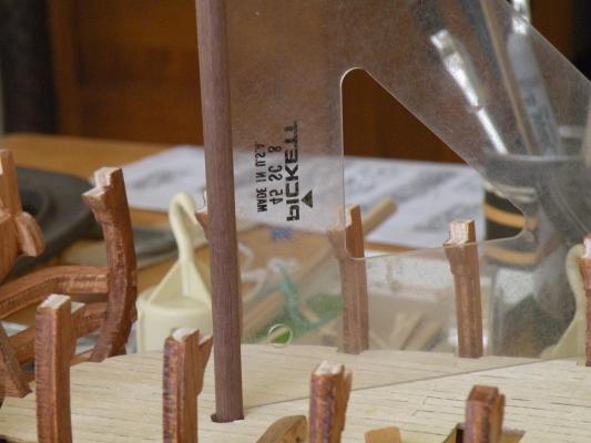
I assume you mean you cut them with a little saw. That would solve my issue. Don't know why I never adopted that. I bought this nipper type tool which uses a razor blade (its on one of my pics) and it cuts really cleanly but like I said, hard to get a true right angle.
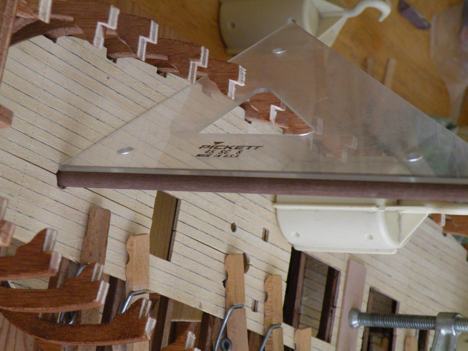
I went and checked the slope of the three masts. Dom was correct 66.7% of the time. At least what I could glean from my plans and a triangle, the foremast and main are perpendicular to the keel. It does look like the mizzen has about a 4 degree rake aft. I'm not worried about this. My thinking is this: it either doesn't matter at all or whatever rake needs to be put in can be done with rigging. On many sailboats nowadays (mine included, when I still owned her) you have an adjustable backstay which you tighten up when sailing upwind (unless your a lazy sailor like we were often times). This puts a slight rake aft into the main mast. I think this could apply to a mizzen mast as well, and from what I'm seeing on my model, the mast is tall enough to bend 4 degrees with no problem given tension on the backstay. All this assuming there is a backstay which may not be the case.
The "twist" I referred to is simply the mast being able to rotate in the hole. Your's is probably a nice tight fit that won't. Mine, I was afraid, would end up too loose (since I always seem to take off more material than necessary) and would do the twist. I would then have had to call the ship the "Chubby Checker."
- Larry Cowden and Eddie
-
1
-
 1
1


HMS Bounty by Captain Al - FINISHED - Artesania Latina - Scale 1:48
in - Kit build logs for subjects built from 1751 - 1800
Posted
Something happened before I got to the questions I have so I started a new reply to myself.
After going through the whole process described above, I had to wonder if there is a better way. I doubt there are going to be too many instances where door handles are to be put on exact opposite sides, and I'm fine with the solution I did even though there is a bit of bolt showing through. My questions really pertain to putting the eyebolts through thin veneers in the first place. If you don't poke all the way through, will two or three mm s of ply be enough to hold the bolts? If you do poke through, how best to nip off the ends and file or grind them fair? Someone on Mike's log mentioned nippers in the context of plank bending. Are there other kinds of nippers that will cut brass rod right flush to the surface? My wire cutters are pretty crude, still leaving a bit of brass standing proud. Another general question is whether most of you attach the rings to the bolts before putting them onto the wood or put the bolts into the wood and then add the rings. I find doing the rings first makes it easier.