
JerryTodd
-
Posts
788 -
Joined
-
Last visited
Content Type
Profiles
Forums
Gallery
Events
Everything posted by JerryTodd
-
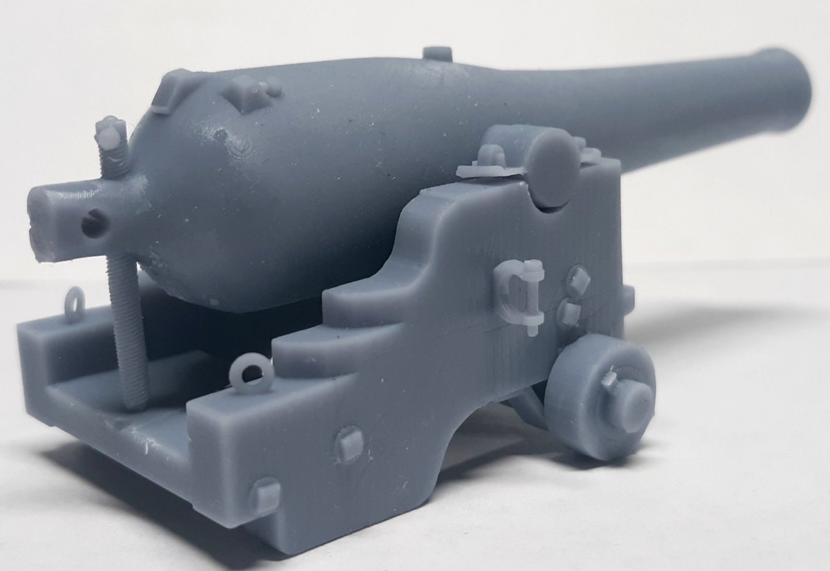
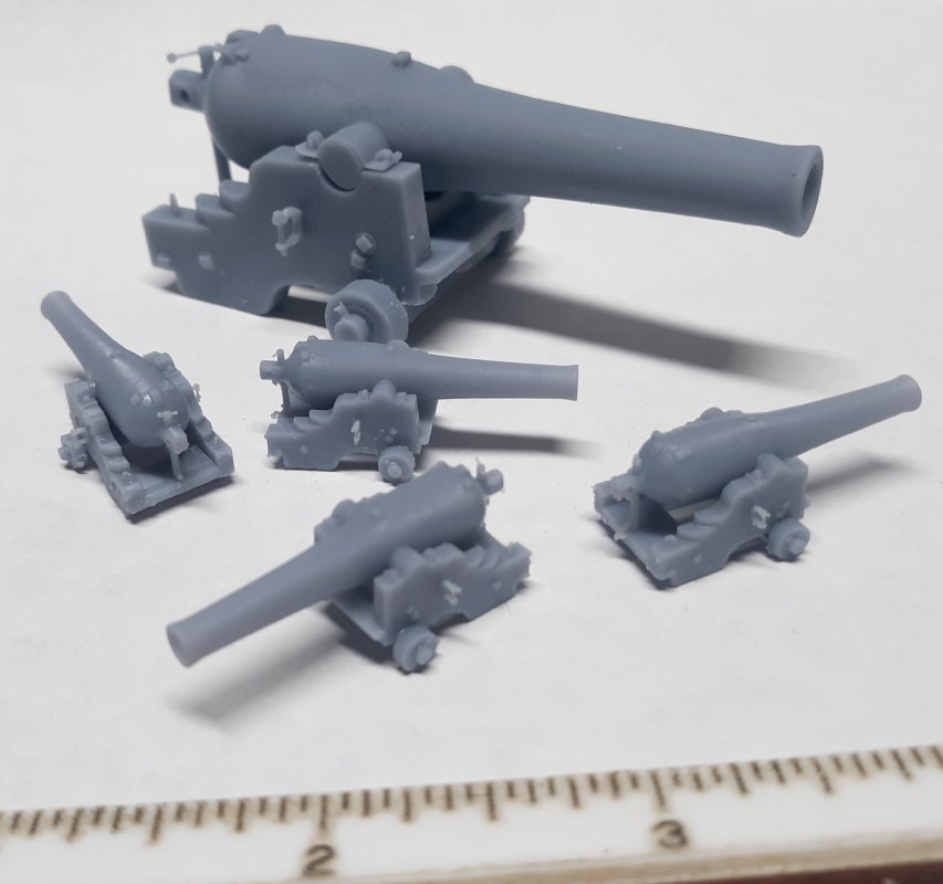
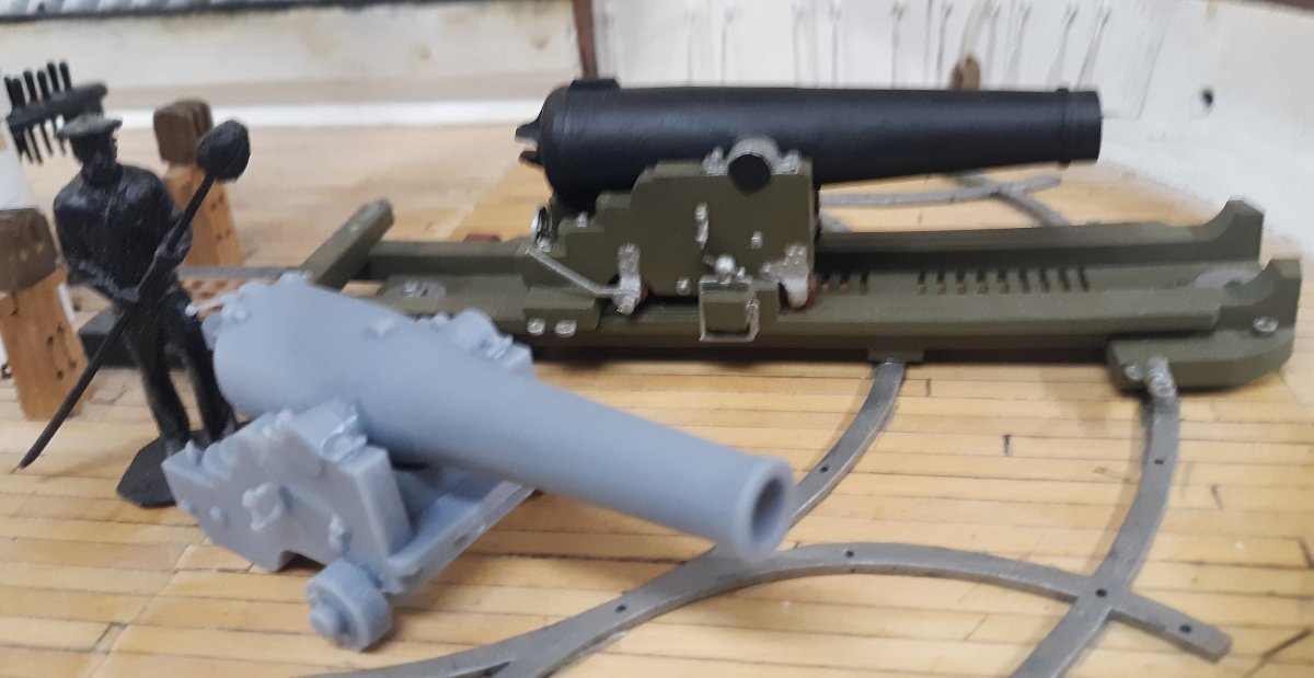
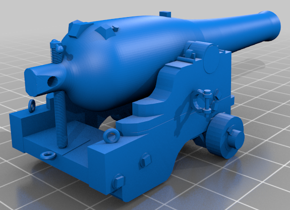
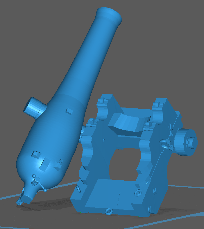
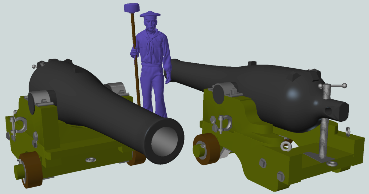
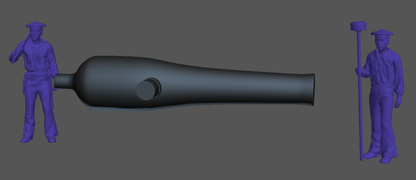
 The resolution is high enough to get a good finish, but since it prints in layers there's going to be some lines and that butterfly wing texture. It's as much or more dependent on the 3D model. The gun tube I made from a 64-sided cylinder then applied a "smooth" feature to it after getting the general shape, which made it 192 sided, I think. More smaller smaller polygons looks smoother than fewer bigger ones. The trucks are 32-sided, and you can see the facets on them. My models are mostly "low-poly" because it's a habit I got into making 3D models for a flight sim back in the early 90's when too many polygons would stop the sim dead in it's tracks. It's akin to my programming from back then too when a 30 meg hard drive cast $700. The pivot gun on the left is the "low-poly" tube I made years before I ever 3D printed anything. The one on the right got a higher-poly tube which is much better visually. These are 1:36 scale. Scaling them down to say 1:48 or 1:76 might reduce the visibility of faceting on something like the trucks, but you'd still see it on the gun barrel. Resin printing is very faithful to the 3D model that way.
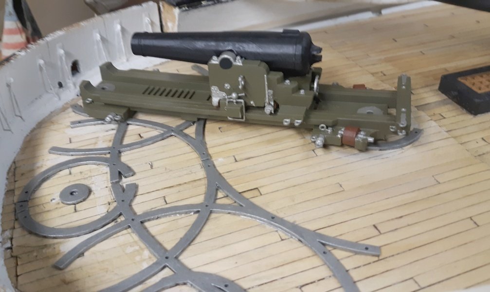
- 524 replies
-
- 4
-

-

-
- sloop of war
- constellation
- (and 3 more)
-
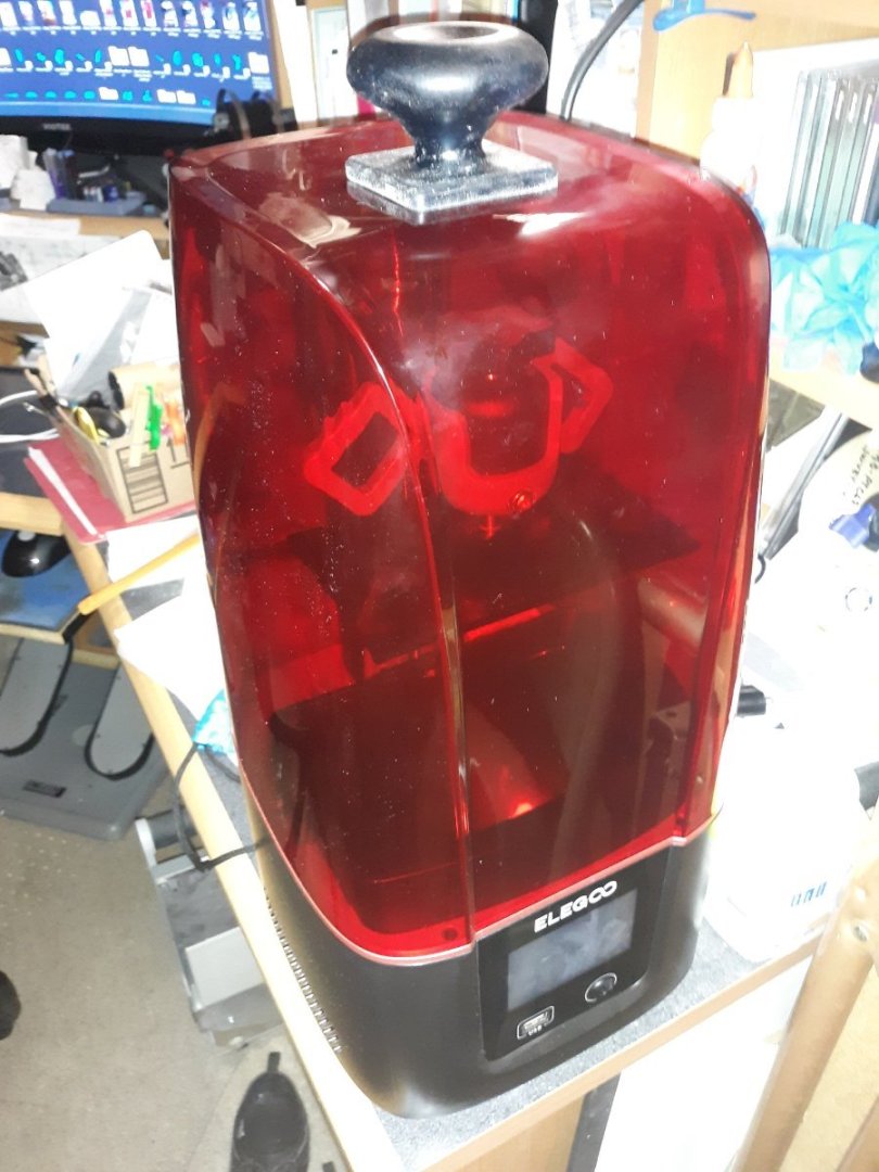
I use Siraya Tech "Build" resins ("smokey black" and "sonic gray") in a Elegoo Mars 3.
- 524 replies
-
- 1
-
-
- sloop of war
- constellation
- (and 3 more)
-
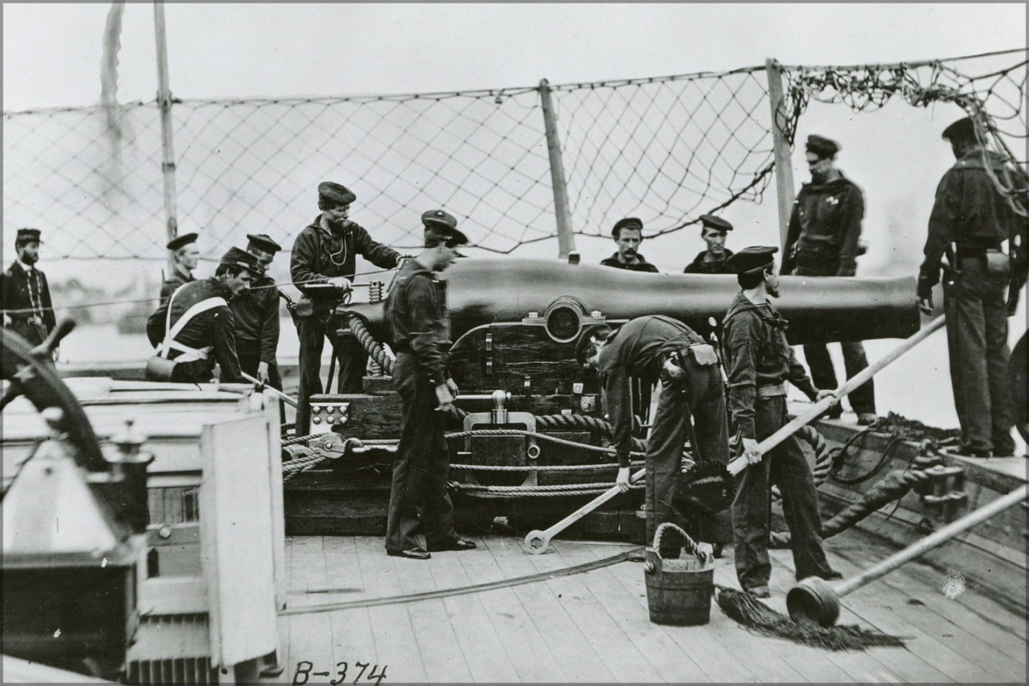
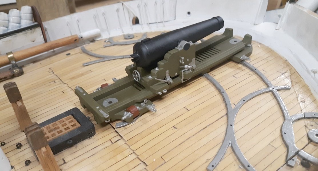
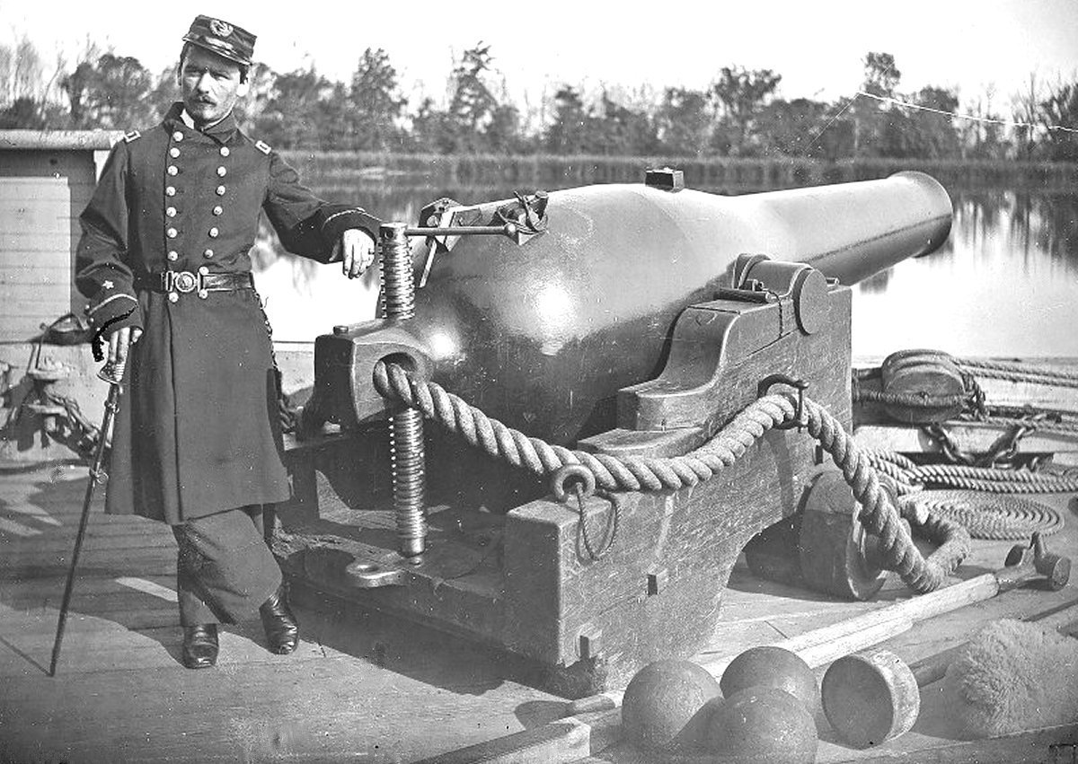
The first gun I started on was the on a pivot carriage. It's not one on my list, but the Lane had a 9" pivot, so this one will be printed in 1:96 scale for that purpose. The carriage is based on the photo taken onboard the gunboat Mendota or Miami, anyone's guess. While I think the slide is the "standard" one you usually see under the 11" gun, the carriage is different and looks to be a truck or Marsilly carriage, stretched a bit. I started building the 3D model while searching for drawings and images that might show me the parts obscured by the crewmen. The Marsilly carriage, on the other hand, I have plenty of data for, and actually had it's 3D model made inside a couple of hours. I printed the four 1:96 scale models needed for the Lane which came out nicely, though scaling it down that small lost some details, like the eyebolts. This gun and mount are on my list of Constellation's guns, so I tried to print one in 1:36 scale and failed twice. I eventually separated the tube and the carriage into two parts and managed to get a usable print. The trunnions were a little out of round, but I brush resin on the parts and zap them with UV light to "glue" them together. Any remaining gaps are filled with liquid resin and zapped, so that wasn't really an issue. I did lose the eyebolt on the back of the carriage getting it loose from the supports, but I'll drill and place a metal one there to replace it. Here's the 1:36 scale mother Dahlgren and it's 1:96 scale "chicks" and on Constellation next to her 10" pivot mounted shell-gun - both 1:36 scale. I still haven't found more drawings or images of the 9" pivot mount, except one photo in the series that has the back of the gun in the background, and a much better version of the photo posted above that's easier to see the details in. Since I don't need it for my list, I may only print it in 1:96.

- 524 replies
-
- 3
-
-
- sloop of war
- constellation
- (and 3 more)
-
Getting into a discussion on guns for another member's model of the Harriett Lane, got me thinking about Constellation's armament, and how it changed over her life. I thought it would be nice to model a sample of all the guns the ship carried over the span of her career. to sit with her when-ever she's on static display. Modeling 9 inch Dahlgren tubes in 1:96 for the Lane got me thinking of this. So, the ship was armed as below at various point over time. At Commissioning 16 x 8-inch shell guns on 4-truck carriages 4 x 32-pounder guns on 4-truck carriages 2 x 10-inch pivot mounted shell guns (removed July 15 1859) 1 12pdr Dahlgren boat howitzer (in launch) During the Civil War 16 x 8-inch shell guns on 4-truck carriages 4 x 32-pounder guns on 4-truck carriages 1 x 30-pounder pivot mounted Parrot Rifle (bow) iron carriage? 1 x 20-pounder pivot mounted Parrot Rifle (stern) iron carriage? 1870's 8 x 9-inch Dahlgren guns on Marsilly carriages? 1 x 100-pounder Parrot Rifle on wood carriage (gundeck starboard #6 port enlarged to 10ft) 1 x 11-inch Dahlgren on iron carriage (gundeck portside #6 port enlarged to 10ft) 1914 20 x 24-pounder guns borrowed from Constitution for Celebration of War of 1812 in Baltimore 1956+ 24 x 24-pounder guns Making one of every gun she's carried will require modeling and printing the following list: 8-inch shell gun on 4-truck carriage 32-pounder gun on 4-truck carriage 10-inch pivot mounted shell gun 12pdr Dahlgren boat howitzer 20-pounder Parrot Rifle on iron pivot carriage 30-pounder Parrot Rifle on iron pivot carriage 9-inch Dahlgren on Marsilly carriage 100-pounder Parrot Rifle on wood shifting carriage 11-inch Dahlgren on iron shifting carriage 24-pounder gun (early 1800's vintage) This was because of her mistaken identity as the frigate, but she carried them just the same. I'll built these so they'll be scalable from 1:96, up to 1:36, and most likely I'll make the STLs available separately on Thingiverse.
- 524 replies
-
- 4
-
-
- sloop of war
- constellation
- (and 3 more)
-
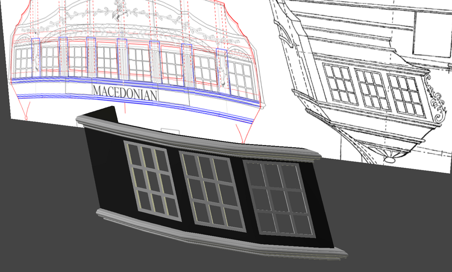
Still fiddling with getting the transom to line up with that quarter galleries. I stamped the image of the transom on the 3D slab and I'm just not liking the way it's going. I'm going to measure the model and build from station 32 aft as accurate to the physical hull as I can. The curved baseline of the transom, and the two levels of the counter under that (not visible in the images) are built and unchangeable, everything else is flexible, even the width, to a point.
- 81 replies
-
- 2
-
-
- macedonian
- frigate
- (and 2 more)
-
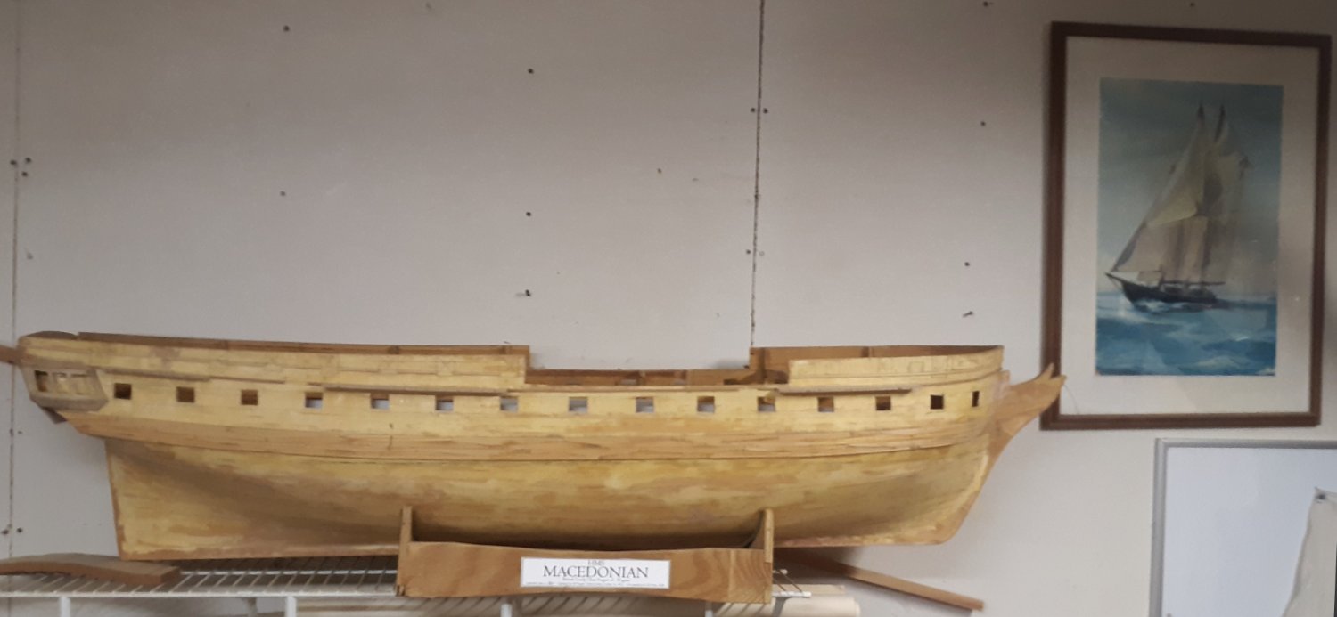
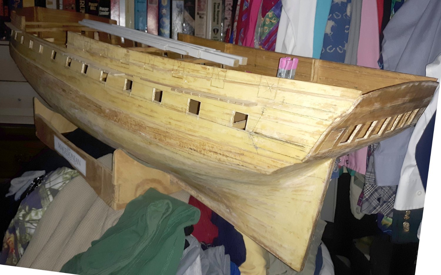
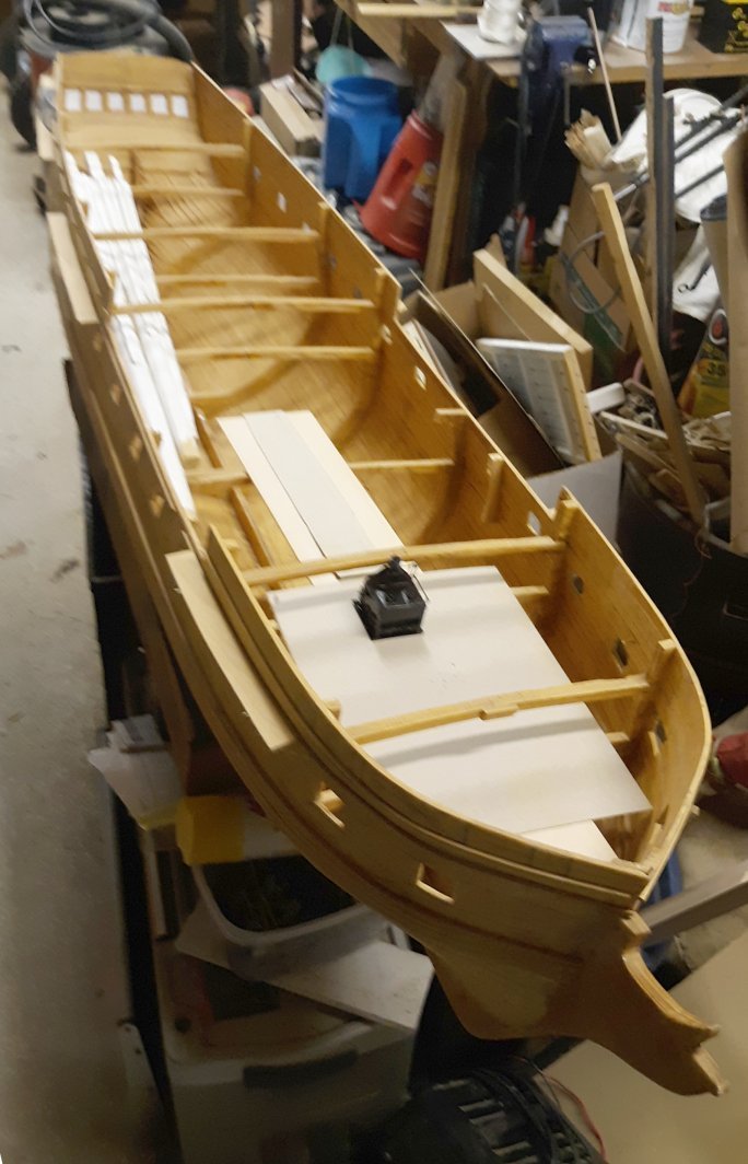
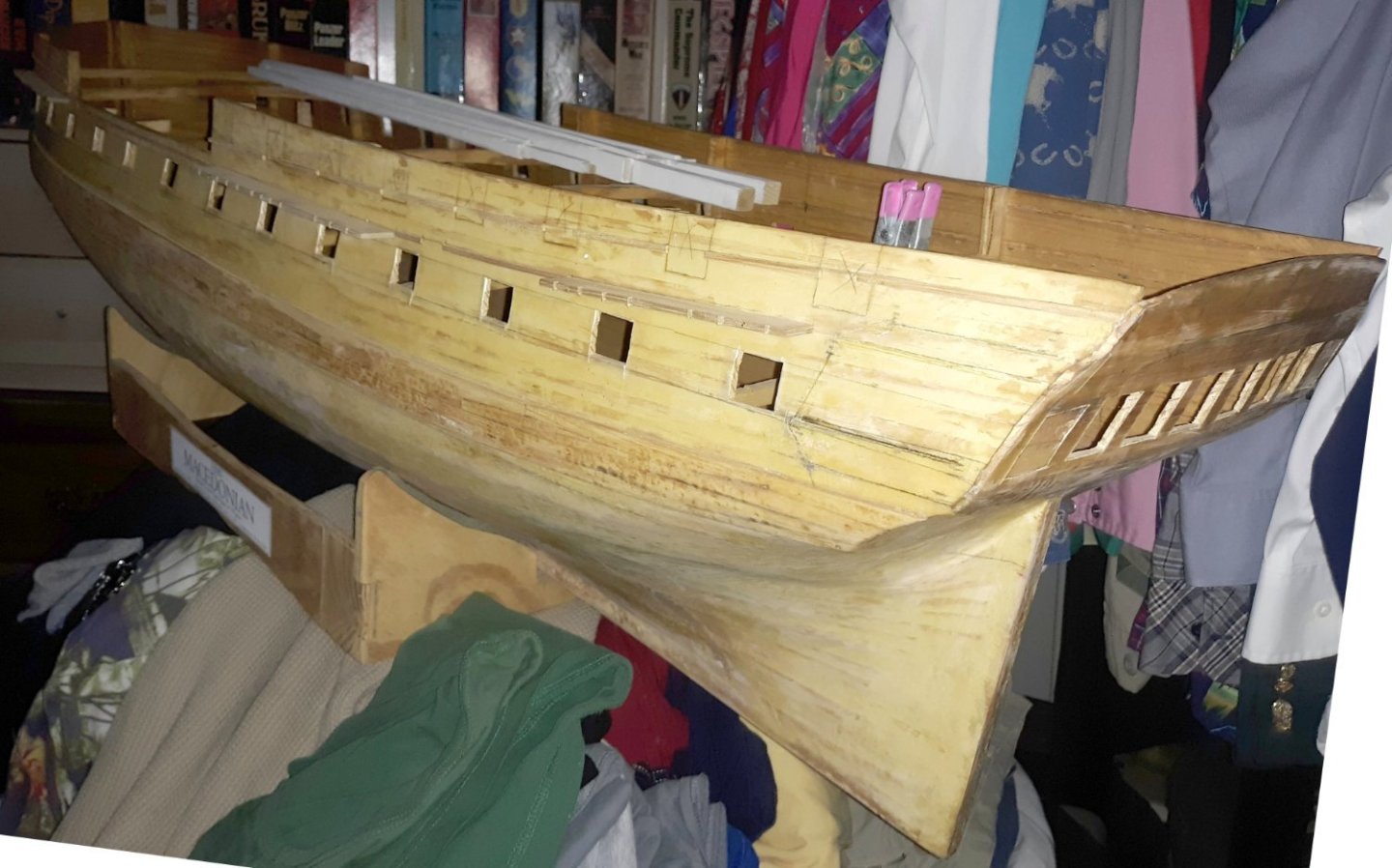
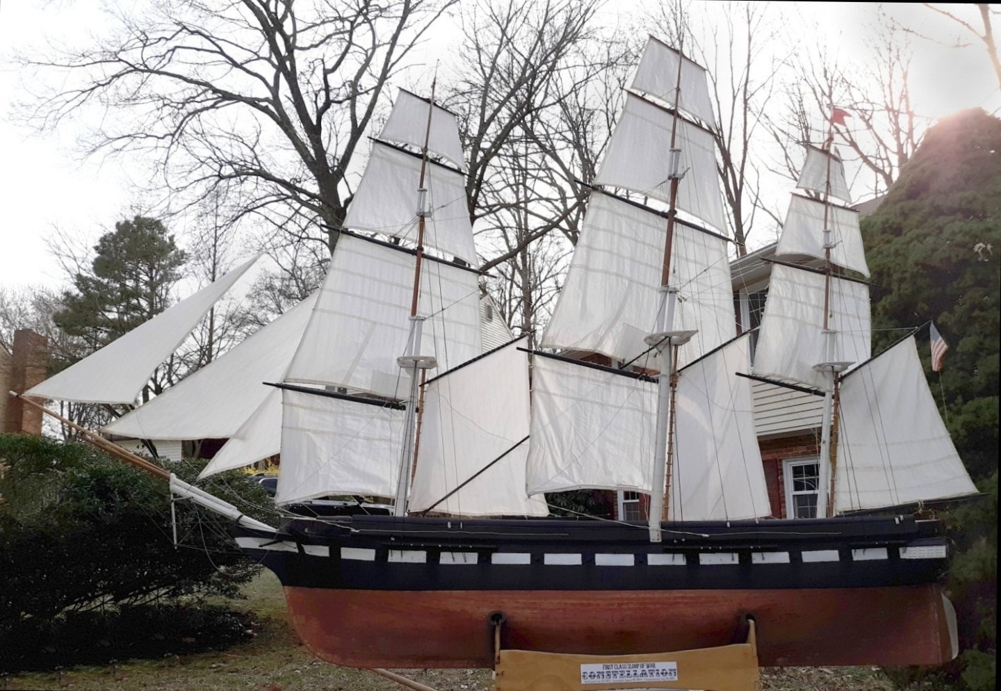
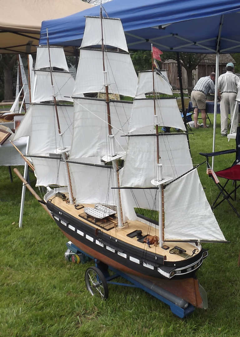
Here's the most recent photos of the model. She's at the rear of the column when it comes to getting worked on, with two models ahead of her. Oct 22 2023 Jan 4 2024 Feb 6 2024 , I removed the quarter galleries in prep for the 3D printed ones I'm working on.

- 81 replies
-
- 2
-
-
- macedonian
- frigate
- (and 2 more)
-
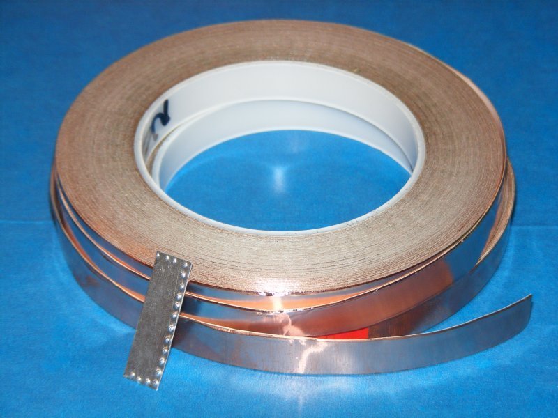
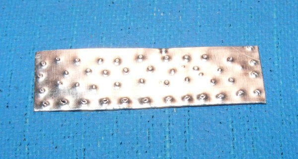
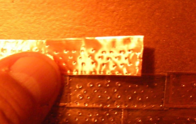
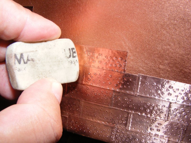
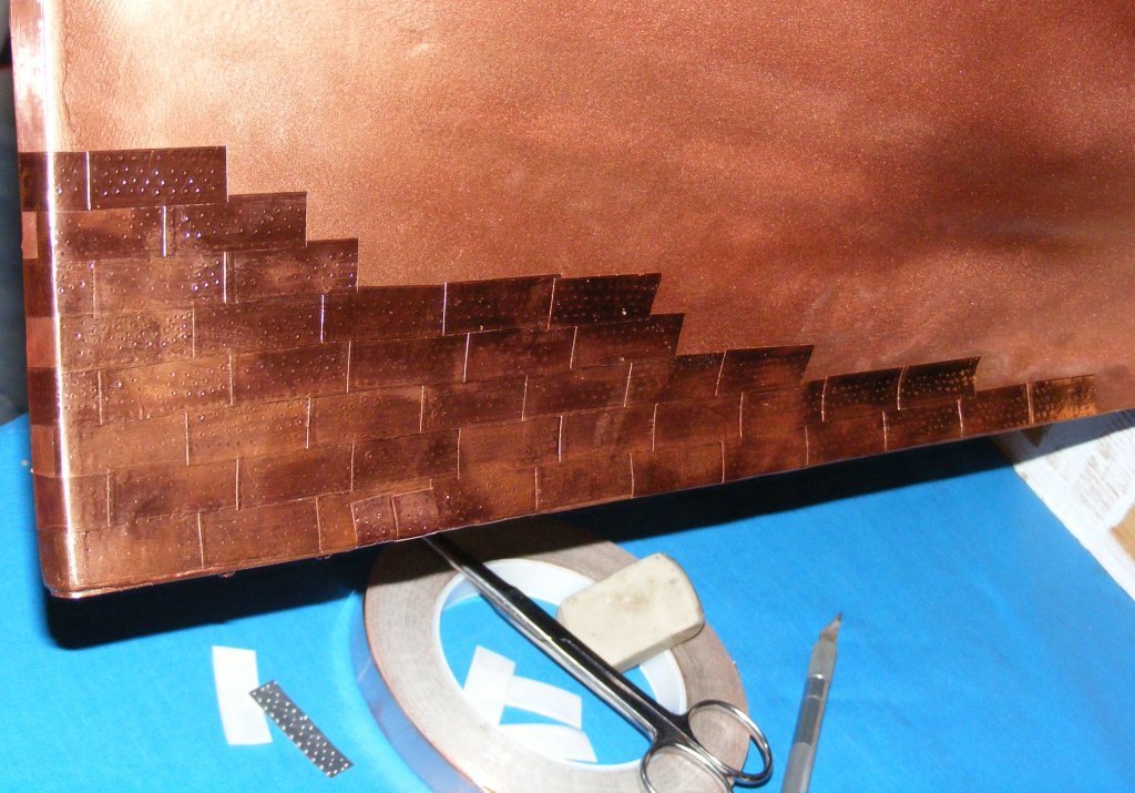
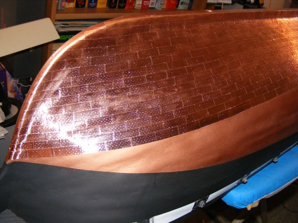
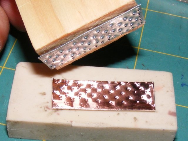
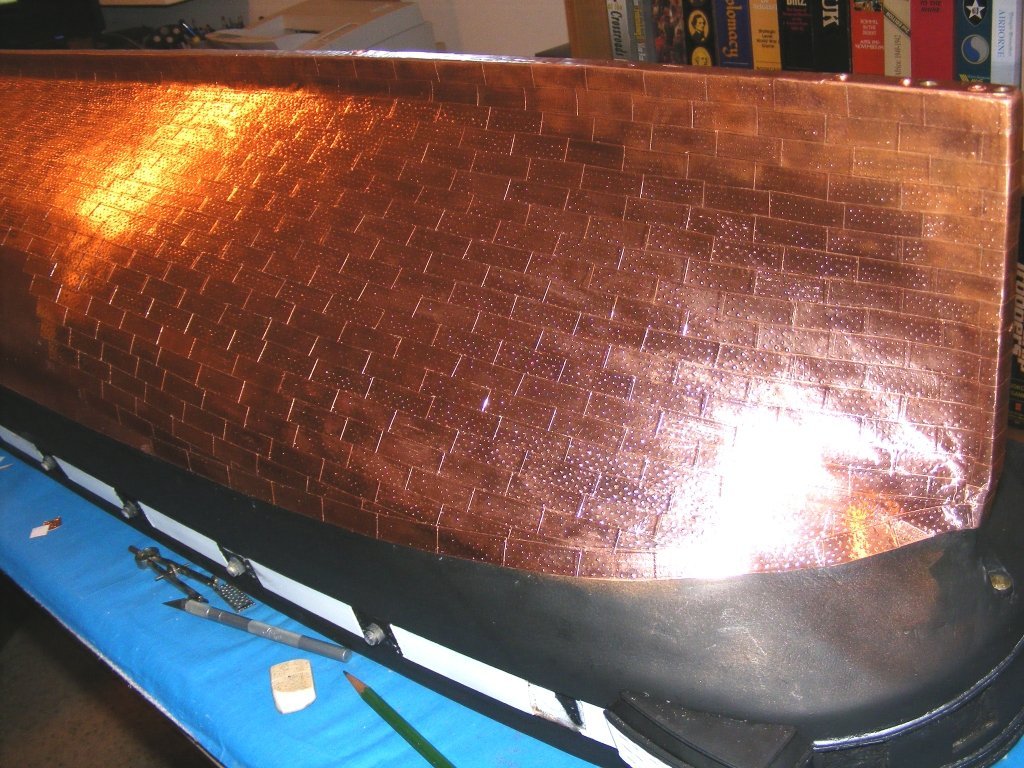
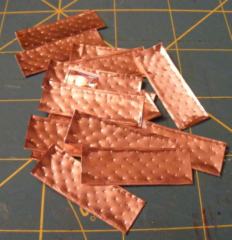
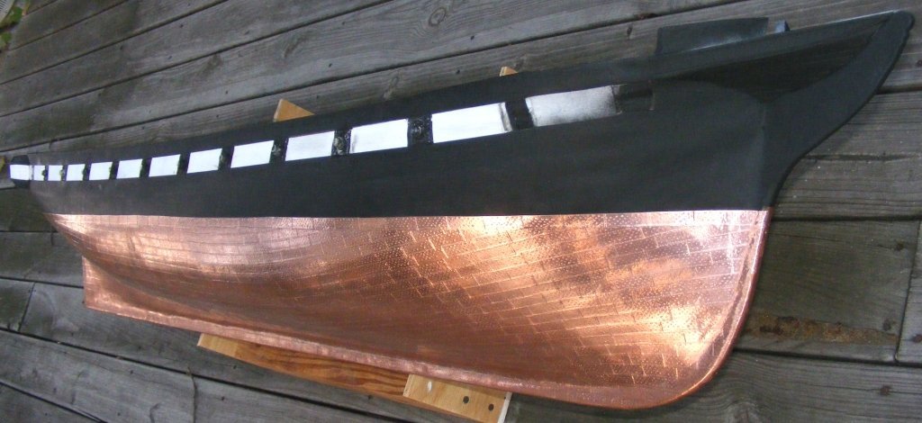
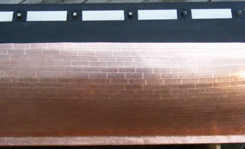
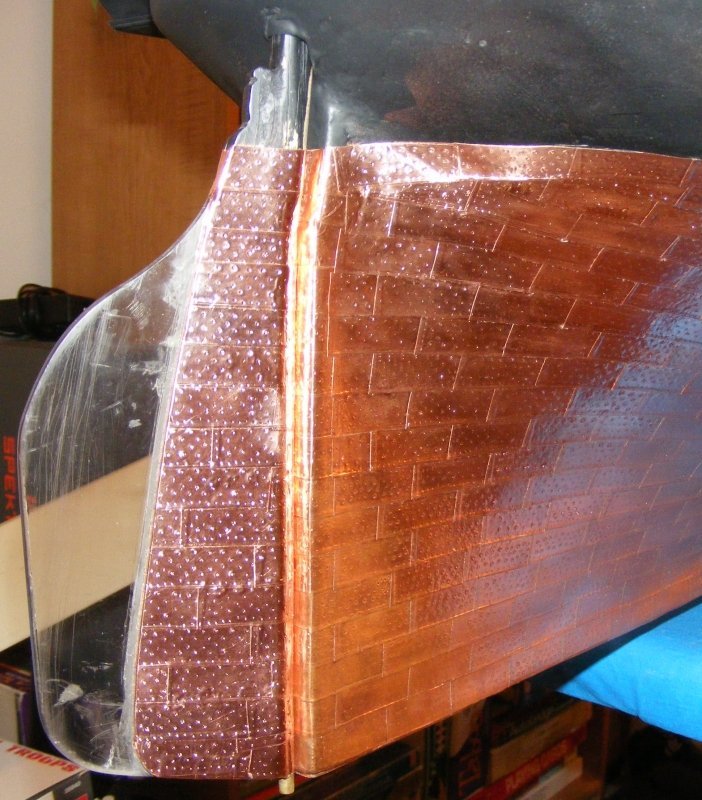
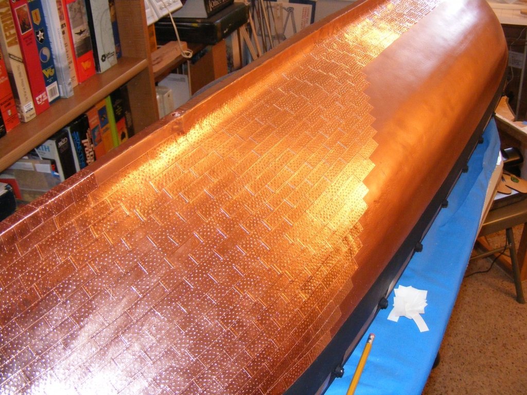
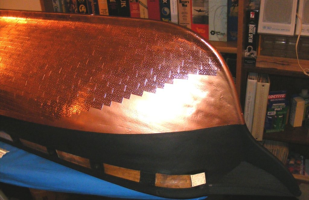
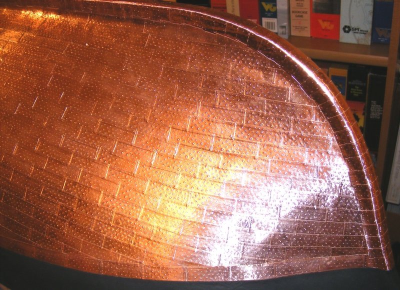
I never rely on restorations and recreations as a source for a model, unless the model is of the ship as it exists. Constellation is no longer coppered, they can't afford it, or much else, and the people in charge are not historians. The current spar deck arrangement was based on 1:96 scale plans from A.J.Fisher drawn based on the ship as she appeared in 1941, which is not how it was during the American Civil War, as the restoration folks claim to be working toward. When I coppered my model of Constellation, which was launched in 1855, I looked at photos of ships, mostly 1860's to the 1890's. There are no other real sources than this. As stated, restorations are typically no more knowledgeable, and when consulted, usually refer you to their sources (which is how I found out about the AJFisher plans), which in most cases are the books we already consult; Lavery, Lees, etc. There is no "Arming and Fitting of American Ships of War" and the closest thing to it, "The History of the American Sailing Navy" isn't the same sort of book, it's more of a narrative history with a few details rather than a technical guide. At any rate; trying to figure out how Constellation was coppered by looking at photos of her and her contemporaries that showed it; I settled on the "no belt" pattern mentioned a few posts earlier. I painted the hull copper, just-in-case, as this is a working model. I used peel-and-stick copper tape sold by an electrical supplier online. The tape is real copper, uncoated, and meant for indoor/outdoor use. At 1:36 scale I needed tape at least 1/2 inch wide which model suppliers that have it, charge a great deal for, the electrical supplier cost less than half what model suppliers wanted. (click the pics to see the larger versions) I made dimples in a piece of sheet aluminum with a blunted nail, and pressed that onto the front of the copper piece on a "mars" eraser to imply the nail pattern. This also made peeling the paper backing off much easier. Starting at the ship's heel (the lowest point aft end of the keel), I began applying the copper sheets, wrapping them around the back edge of the stern post. The sheets overlap about 1/16 of an inch. Each piece was pressed by hand and gently rubbed with the mars eraser to press it to the hull. This pushed the embossed dimples back out, making a countersunk, flat-head-nail look I was happy with. This went on for a few thousand pieces of tape. On occasion, a piece would have to be cut because it's end was too close to the end of the piece below it. I cut pieces so the end would be 1/4" or more from each other when they would have been closer than that otherwise. When one side was coppered, I worked on something else to let my fingers heal, the coppered the other side. Finally I laid what I called the "dragon scales" on the stem and bottom of the keel. The copper was trimmed to stop at the waterline, and a single row of sheets runs around the hull, covering all the points created by this trim. The copper is therefore 7/16" above the LWL. To the best I could determine, this was how Constellation and her contemporaries were coppered from the 1850 into the 1900's. This may not apply to ships of other nationalities, or built in private yards. Other than the belted, or non-belt patterns, I was mainly concerned with it's appearance fitting the 1:36 scale of my model, which I think it does. This is how the copper looks 9 years later, after several sailings in the brackish waters of the Chesapeake Bay's tributaries.
-
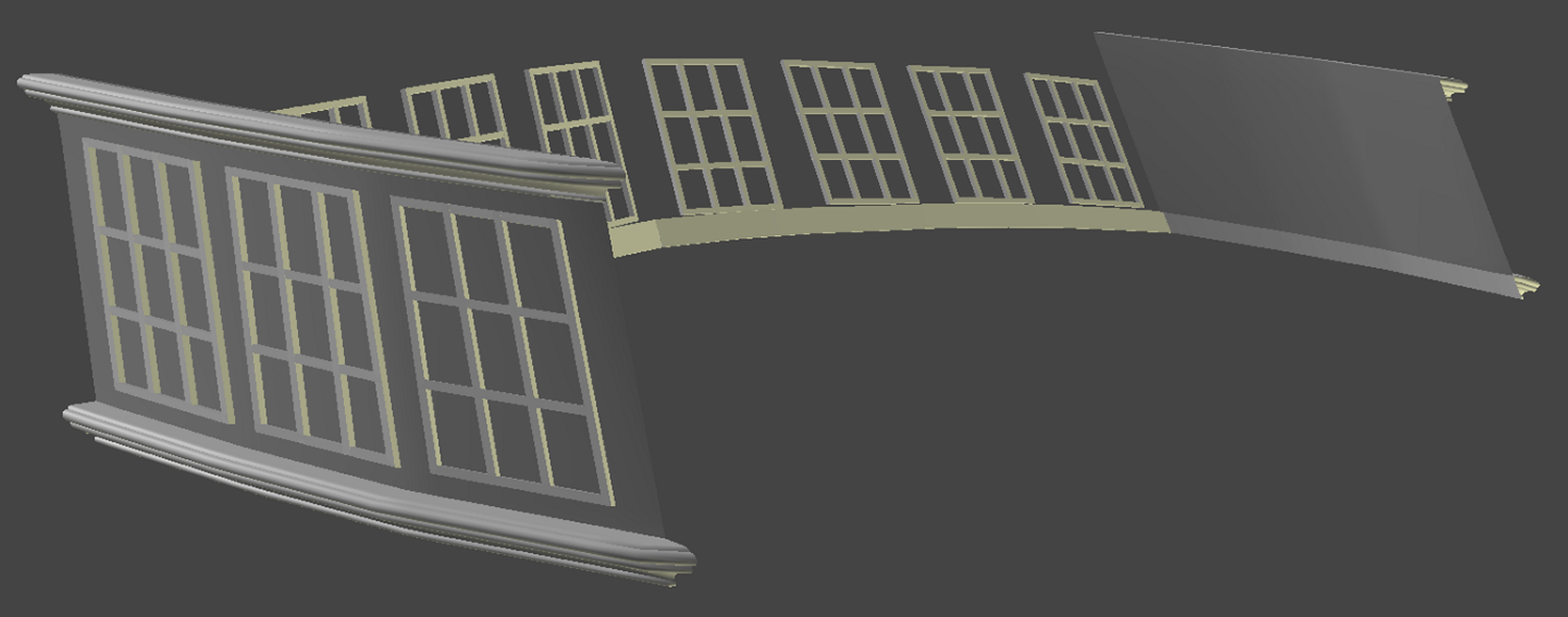
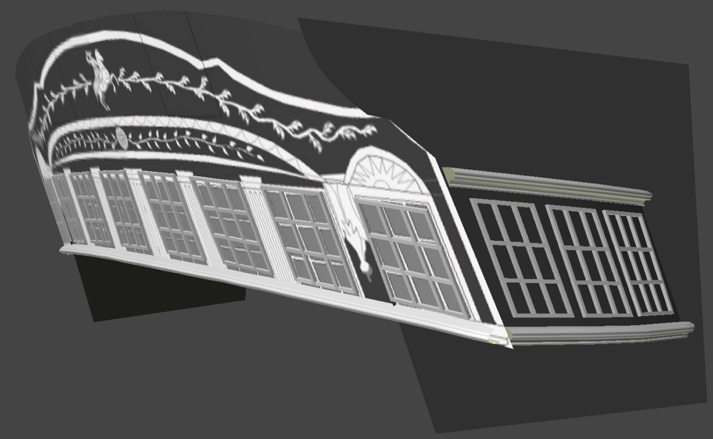
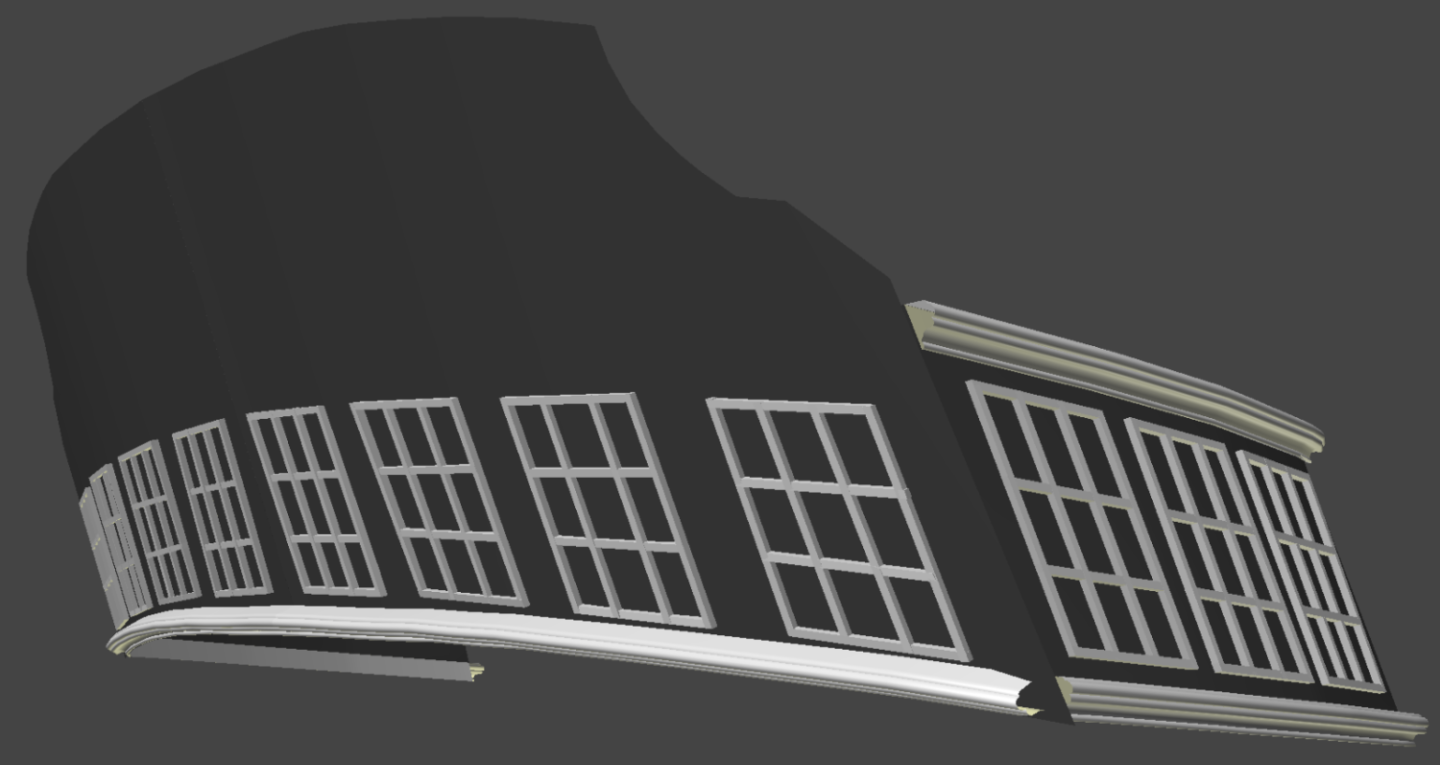
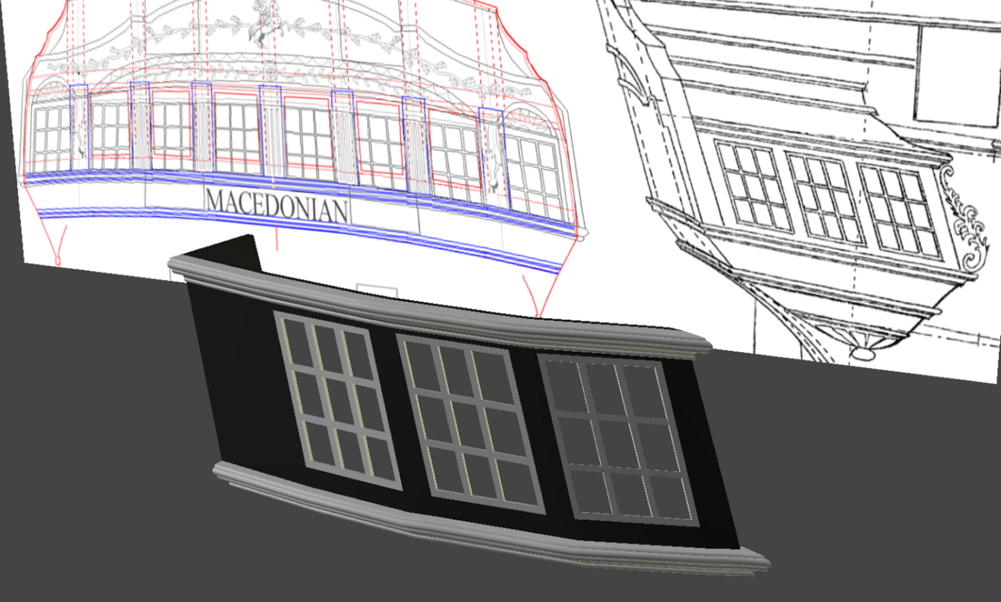
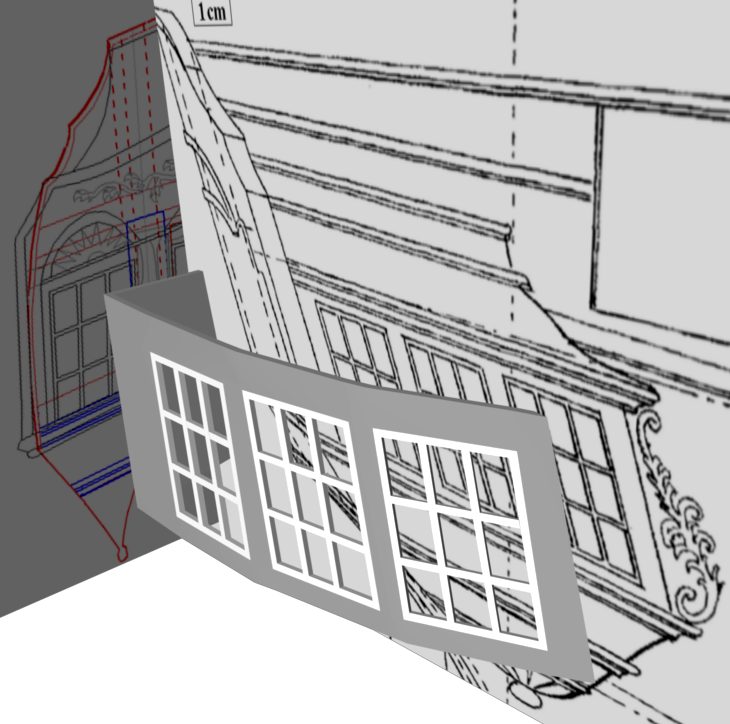
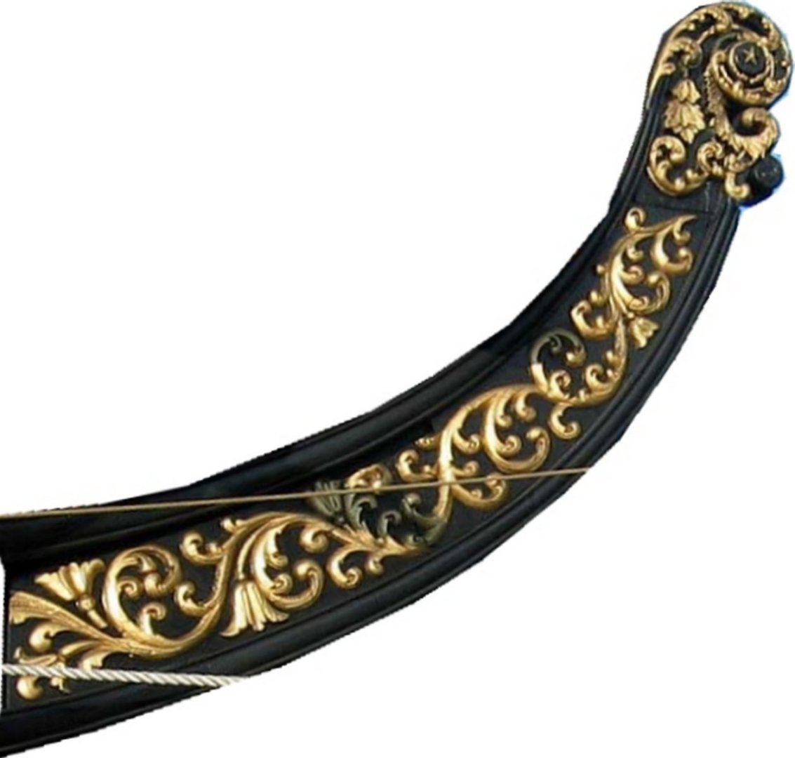
I've decided rather than print things to stick onto Macedonian's stern, like filigree carvings, moldings, and such; I'm going to 3D print the transom and quarter galleries all together; windows, ornaments, moldings, etc. Obviously this won't be printed in one piece, but will be divided into bite-sized portions that will each fit in the printer, and get bonded together on the hull. You folks that think 3D modeling/printing is "cheating," are advised to turn away, you may find what follows to be disturbing. I started this only intending to make quarter galleries, and parts to apply to the stern, but as anyone following my models knows, I often steer a course that would break a snakes back. Basic beginnings. This actually got printed to check against the hull and found to be off-scale. Re-scaled, and resized, I started working out the moldings. Trying to reconcile the quarter gallery to the stern convinced me to make it all one model. There's still a long way to go.

- 81 replies
-
- 5
-
-
- macedonian
- frigate
- (and 2 more)
-
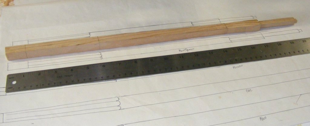
This is a bit after-the-fact at his point, but... While there are businesses today that turn masts on giant lathes, that cheat wasn't available to the mast-makers in the times most of the ships we're modeling were made. Forgoing "built-up" and metal masts, for our purposes, assume we start with a single log, as most spars for models will. This is an abbreviation of the way real spars are made, and once you're accustomed to making spars this way, you'll find it's not so tedious as it seems. I make, and have made, spars in this way for real boats, and models of any scale from 1:96 to 1:20. A stick, is square-cut from a board of straight, clear grain, to the largest diameter of the finished spar. Where the spar has different shapes, such as in the pic below; square heel, 8-sided, round, 8 sided again, square doubling, angled cap-tenon; all are marked along with the taper in each section, if any. Cut the tapers and sizes on all 4 sides. I use a band-saw or scroll-saw on most of it, fine thin saws like a razor-saw on the delicate places. You may need to remark the spar. There's a jig for marking a spar to make it 8-sided, but when the stick is less than a centimeter around, it's near impossible to use; so I divide the width into 1/3 at each end to the taper, and connect the tick marks with a straight edge. Do this to all 4 sides again, then using a knife, scraper, plane, or whatever work best for the size of the spar you're making, and take off the square corners down to the lines you drew to make this portion of the spare 8-sided. The portions of the spar that will be round also are made 8-sided first. For the portions that finish 8-sided, you're done, but for the round portions, you need to knock off the corners to make that portion 16-sided. At small scales this is probably best done with a scraper. Technically you then make it 32-sided, and even 64-sided; but at our scales you just gently knock off corners to get it to round - all done by eye. You will find making yourself a "shooting board" to cradle the stick as you work will be a big help. Cut a strip that's about 1/3 the sticks diameter at 45° down it's length. and glue the two strips to a board so the 45° cut forms a V for the spar to lay in. Put a block at one end for the spar to stop against, and maybe a bock on the bottom of the opposite end to hook your workbench to keep the work in front of you instead of on the floor on the other side of the room. Here's a portion of my work log on a 1:20 scale schooner where I made it's bowsprit from white pine using this method. http://todd.mainecav.org/model/pride/model11.html The lower masts of that 1:20 scale schooner are hollow, and made using the "Bird's Mouth Method" which isn't really practical for smaller scales where the mast is less than 2cm in diameter, but you can see them being made this way here: http://todd.mainecav.org/model/pride/model10.html
- 396 replies
-
- 6
-
-
- Idea
- Bright Idea
- (and 1 more)
-
More often than not, water moves past a hull from bow to stern, so that sheets forward should overlap the ones aft. The same basic principle as the shingles on the roof of your house. In the vertical is another matter, as ship's roll, there really isn't a general flow of water. It could be argued that pitching causes higher water pressure moving up the hull, and why you might want to copper top-down. An argument for bottom-up coppering is the sheets closest to the waterline are the most likely to be damaged; over-zealous cleaning, rubbing against the dock, ice, etc. While either format can be repaired, the bottom-up would be a little easier to repair. Bottom-up coppering also covers the points and narrow ends of cut sheets better than the other way, which leaves them exposed and prone to catch stuff, like seaweed, and get pulled loose. Every photo of a coppered ship, out of the water, that I've seen, the copper was applied bottom-up. Before photography is anyone's guess, since every source I've seen contradicts every other source I've seen, like Lavery and Longridge. On that note; copper was nailed with flat headed nails, counter sunk in pre-punched holes, so the nail heads were flush with the sheet's surface. If your coppering looks like they used the Titannic's rivets, it doesn't matter how they overlap.
-
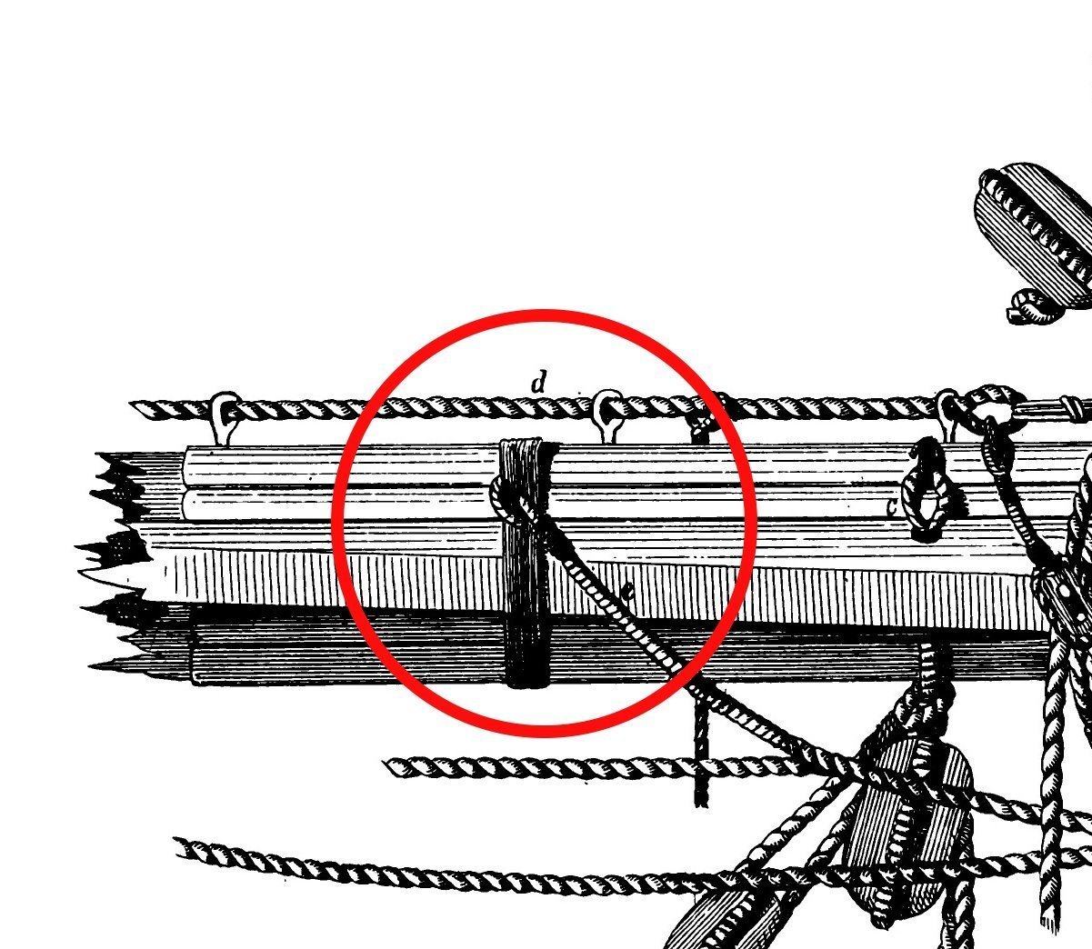
Will the yards be getting jack-stays? (d) I just wonder should the jack-stay eyes be turned that way, or are they just drawn so we can see that they are eyes?
-
I'm contrary and obnoxious, so I'm bound to be around to bother people for a long time. The launch and 1st cutter got gudgeons on their stern posts, and all the boats got lifting-eyes. Decent paint jobs will have to wait for warmer temps so I can use the air-brush to get into all those nooks-and-crannies. I guess I'll work on their rigs next. spars are easy, but I don't think I'll make the sails, but just roll some cloth and bundle it onto the spars. I have some little cleats left-over from plastic kits, and some tiny brass belaying pins I'll put on to detail them a bit more.

- 524 replies
-
- 4
-
-
- sloop of war
- constellation
- (and 3 more)
-
Even a large model at 1:36 scale, and with no permanent rigging up yet, it would be near impossible for me to bend sails to yards without something going terribly wrong. Mine are lashed at every grommet on the head of each sail to a jack-stay on the yards, which I do with a needle and polyester sail-thread, and a very slight touch of CA to set it. Doing this before putting the yard on the boat is SOOOO much easier than trying to do it with the yards already on the boat. Fortunately, there's only 17 sails to deal with.
-
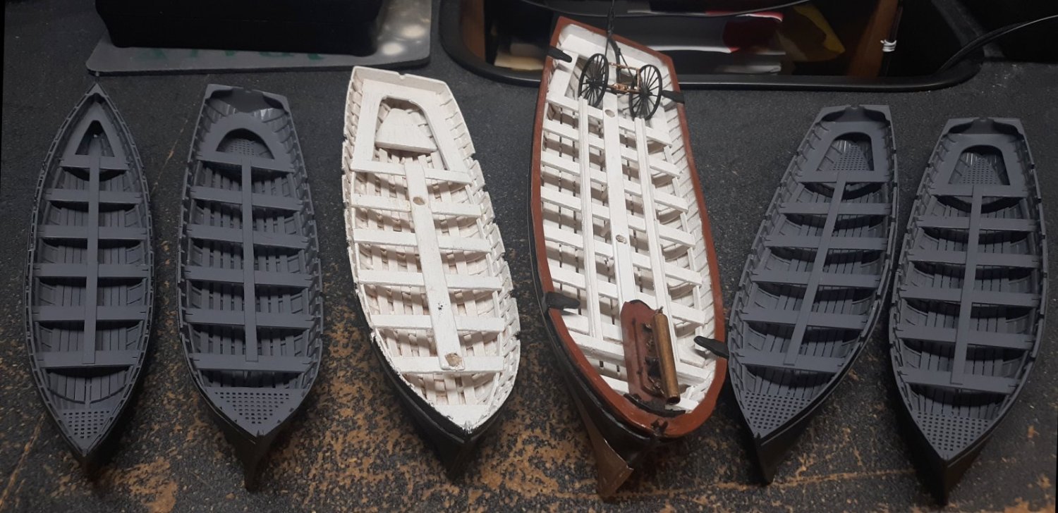
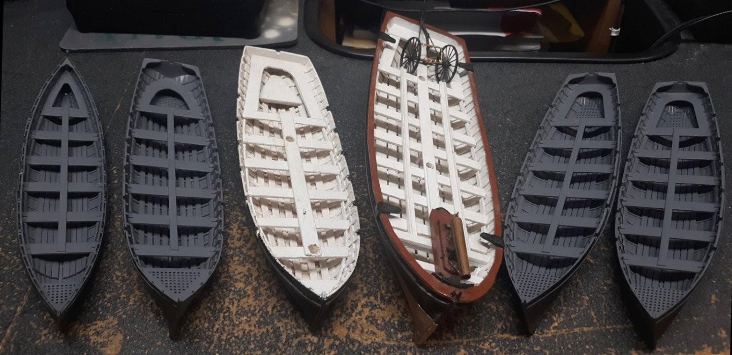
Gave the boats a coat of primer. After I cleaned up the original boats of shop dust, all but the launch got some white paint inside, and black paint outside. when it gets warm enough, all the paintwork will be fined up with the air-brush, gratings will get painted, etc. I still haven't found any sort of "official" pattern boat chock, so I just made some simple ones like we had on a boat I worked on long ago. If I ever find something more "authentic" for Constellation I'll replace these with those. Then I made rudders for the boats, closely followed by tillers. I don't intend to leave the rudders hanging on the boats, but rather stowed safely in the stern sheets, though I may hang them on the 1st cutter and/or launch once I install gudgeons on them. I have some fine copper wire eyes in the parts bins that'll be perfect for this I think.


- 524 replies
-
- 5
-
-
-
- sloop of war
- constellation
- (and 3 more)
-
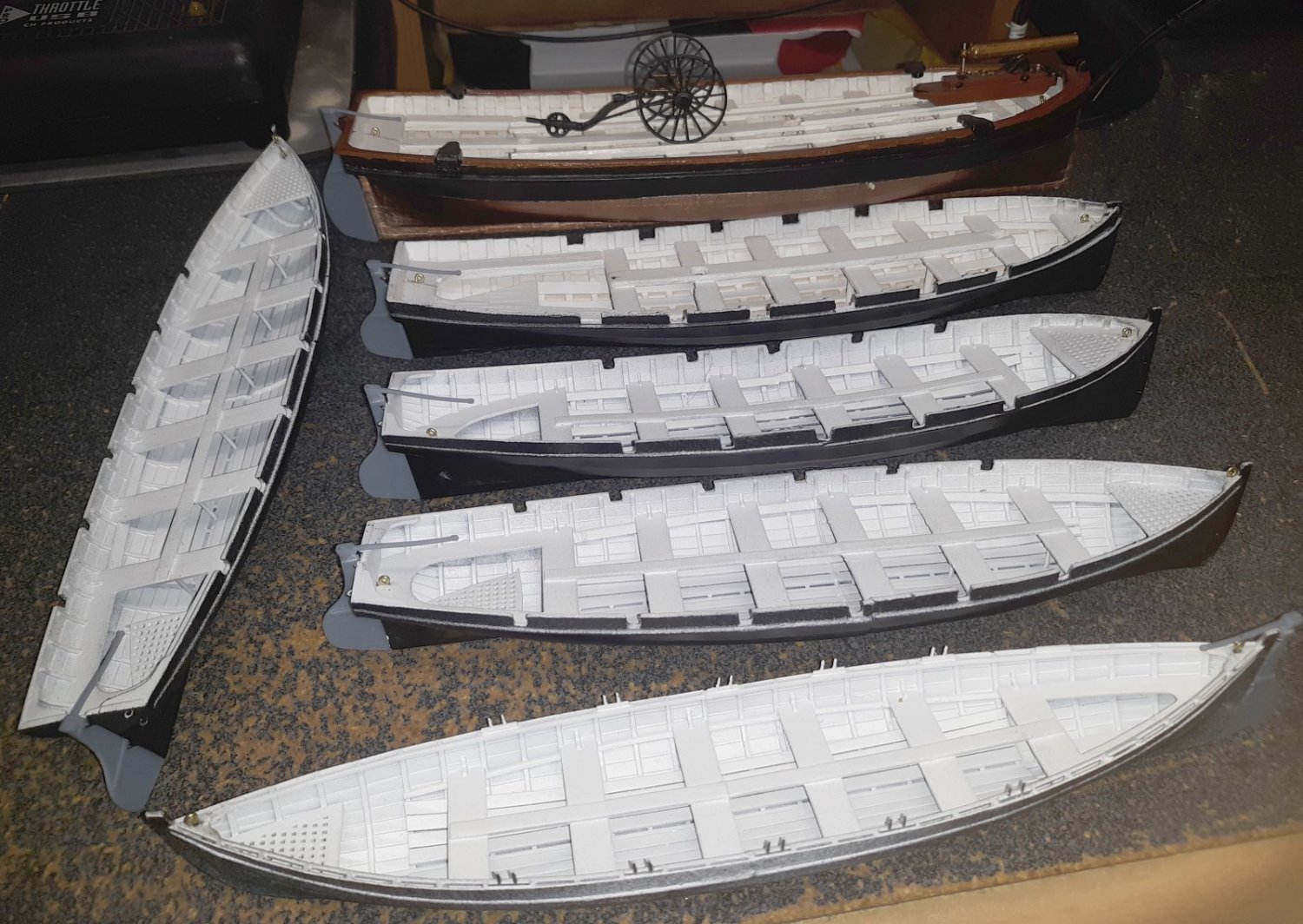
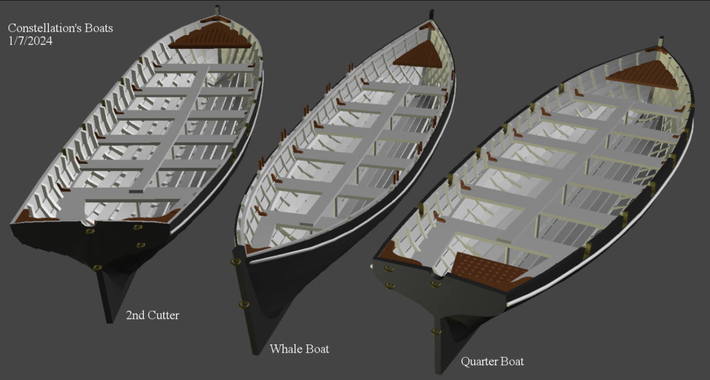
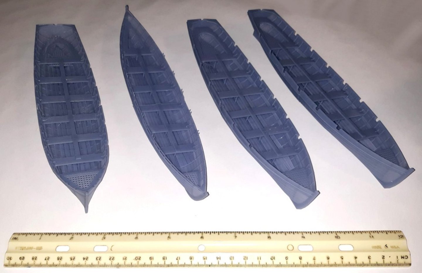
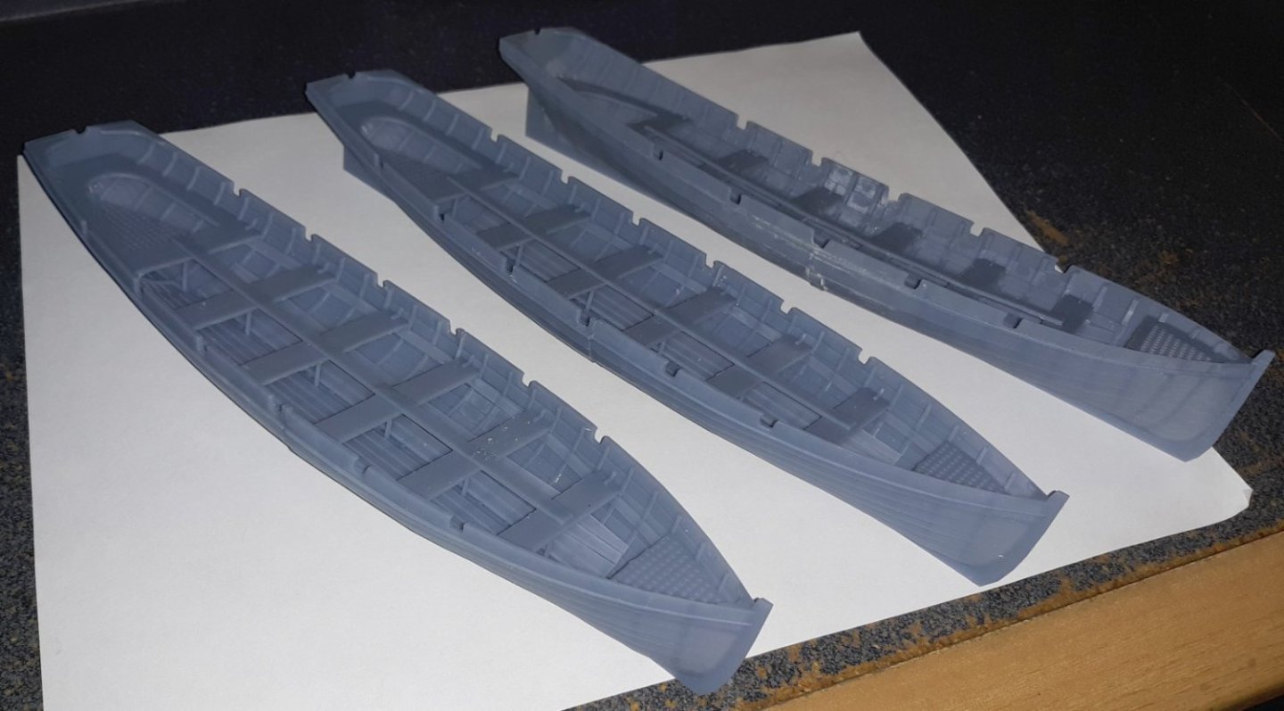
The whale-boat was ready to print by the 7th. The built a whale-boat to these lines for Constellation and fitted her with bronze oar-locks, but I opted to put in thole-pins instead. I split the model in two, to fit in the printer, and made sure there were no "holes." The slicer said it would take 5 hours and 25 minutes to print. Here's the 3D models of all three boats together. As 3D models go, they are very "low poly" so the printed models come out a bit "faceted" but they're still more detailed than the boats I made by hand. I let it run over-night and in the morning found $.83 worth of resin weighing .83 ounces (23.6 grams), and looking very much like a whale boat...broken in half. It came off the plate undamaged, and was sloshed about in a tube of denatured alcohol for a bit; then washed in warm water, and finally sat on some paper towels to dry. Here's all the boats together... the 25'10" 2nd cutter, on the left, is 8.625" ( 219 mm) long, the 28'2" whale boat, in the center, is 9.625" ( 245 mm) long, the two 26' 6" quarter boats, on the right, are each 8.875" ( 226 mm) long.
- 524 replies
-
- 4
-
-
-
- sloop of war
- constellation
- (and 3 more)
-
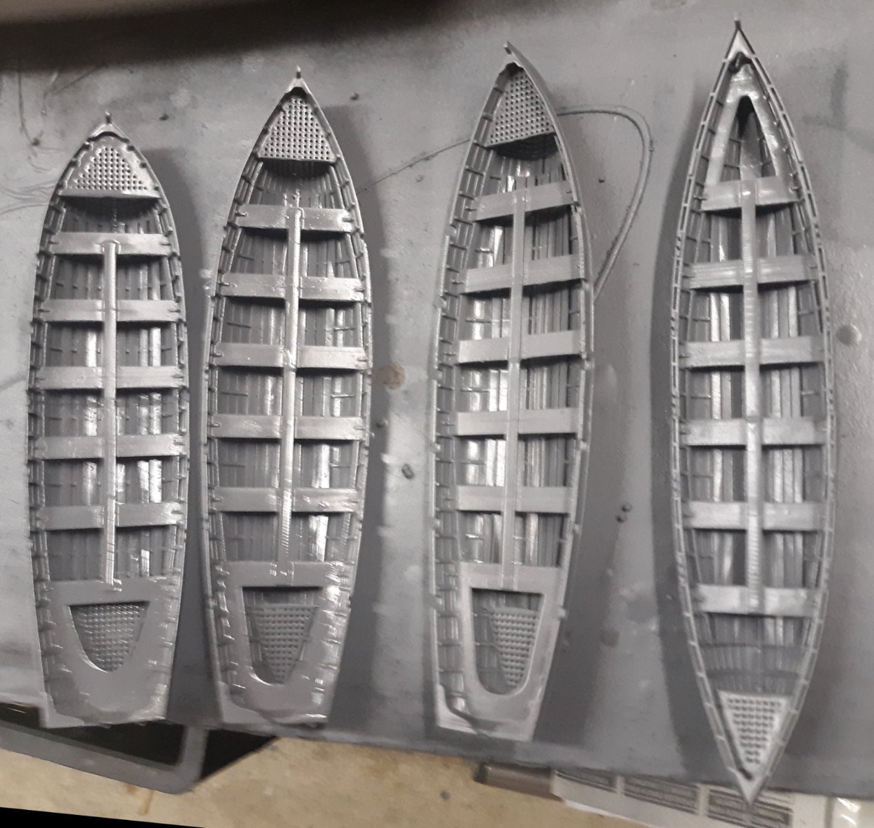
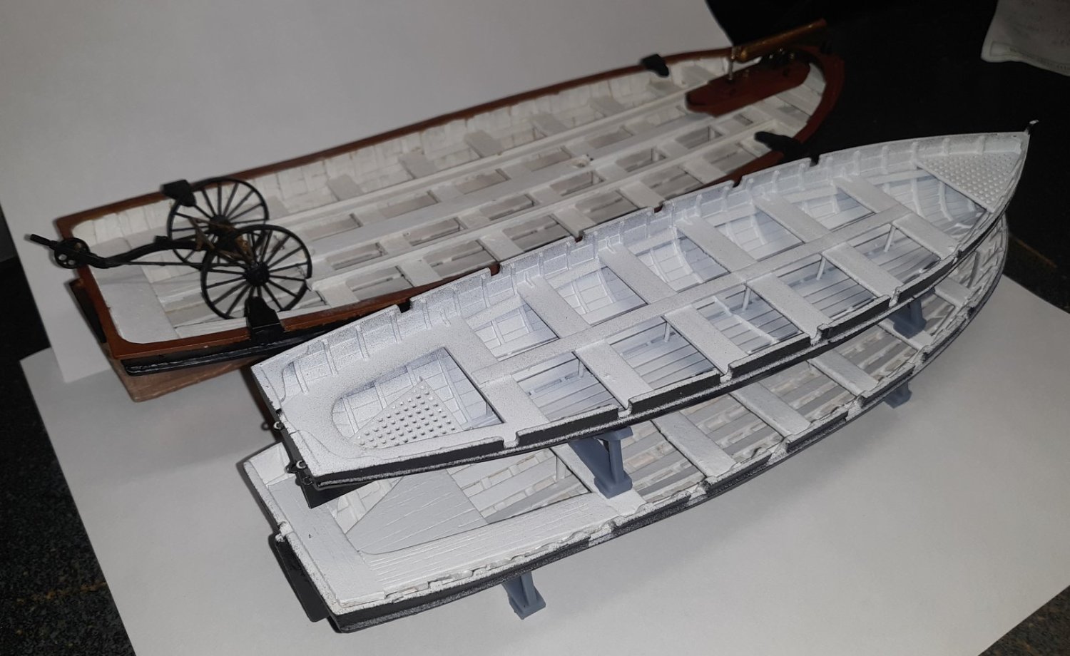
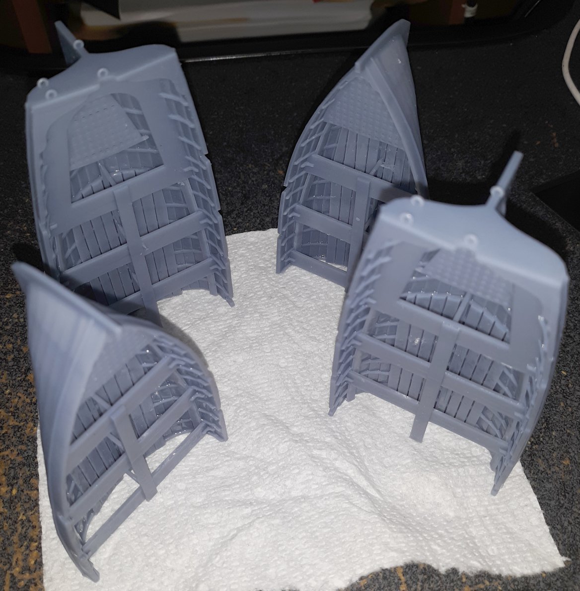
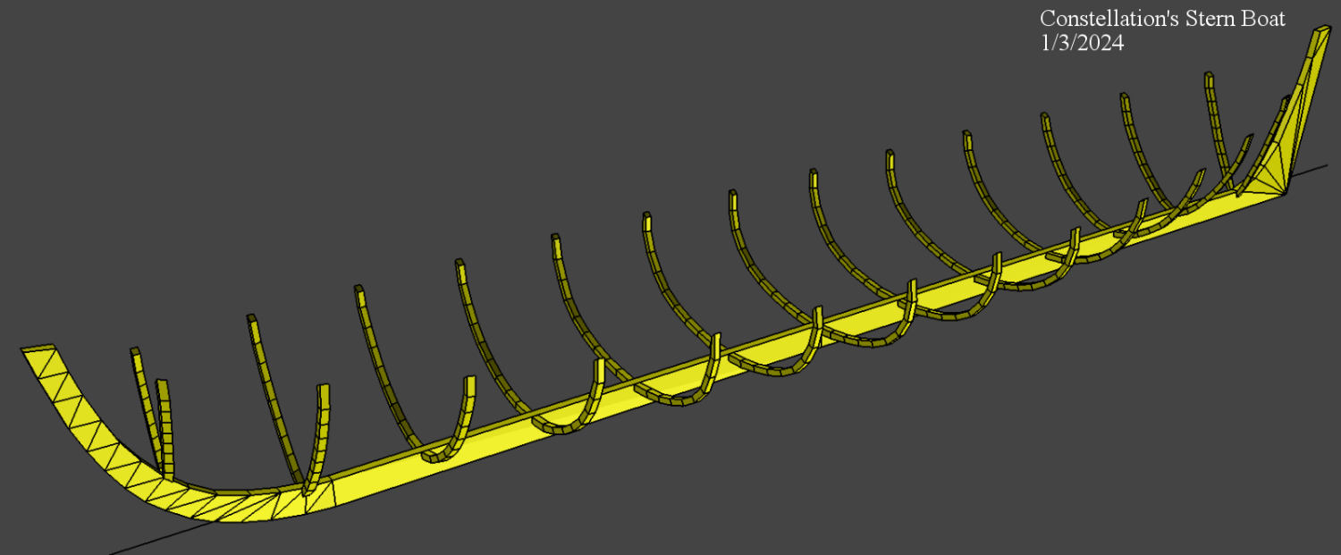
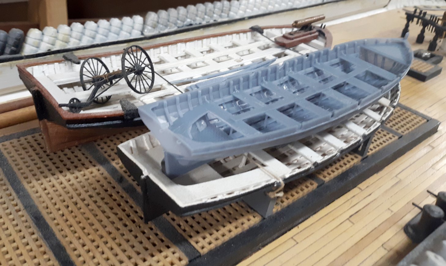
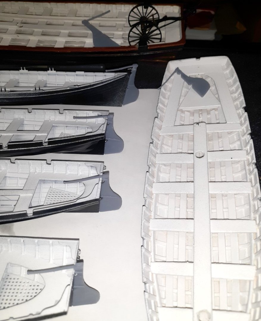
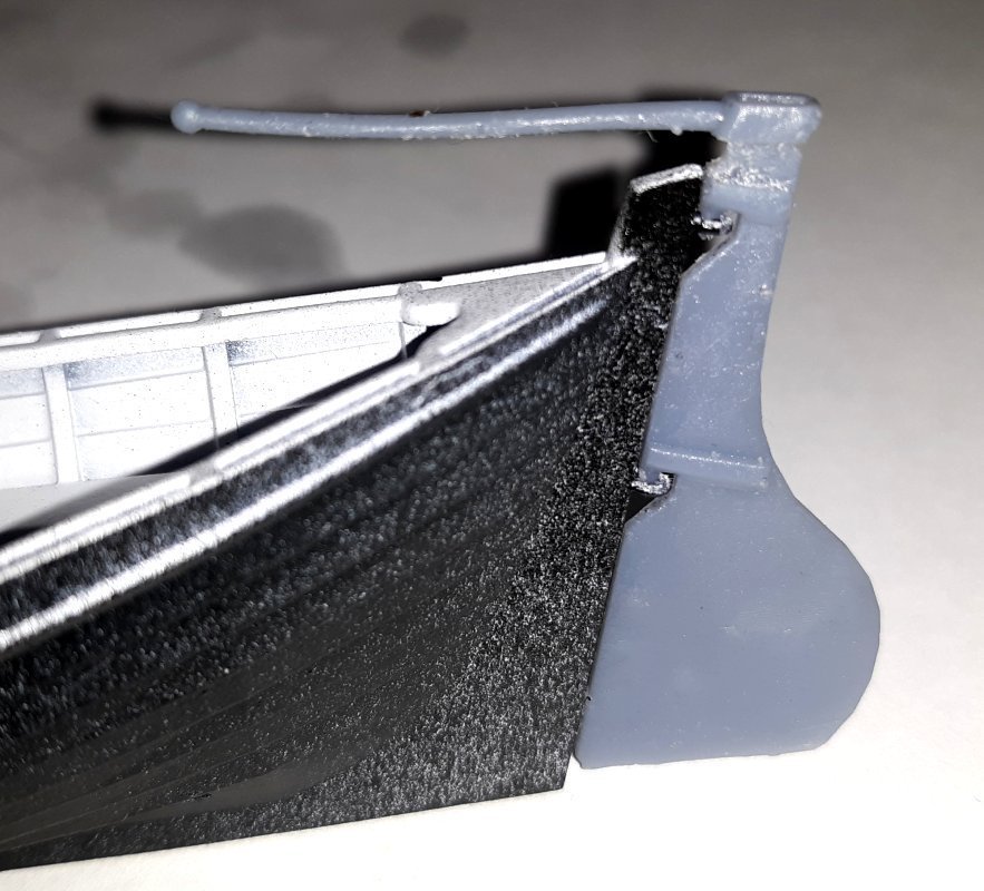
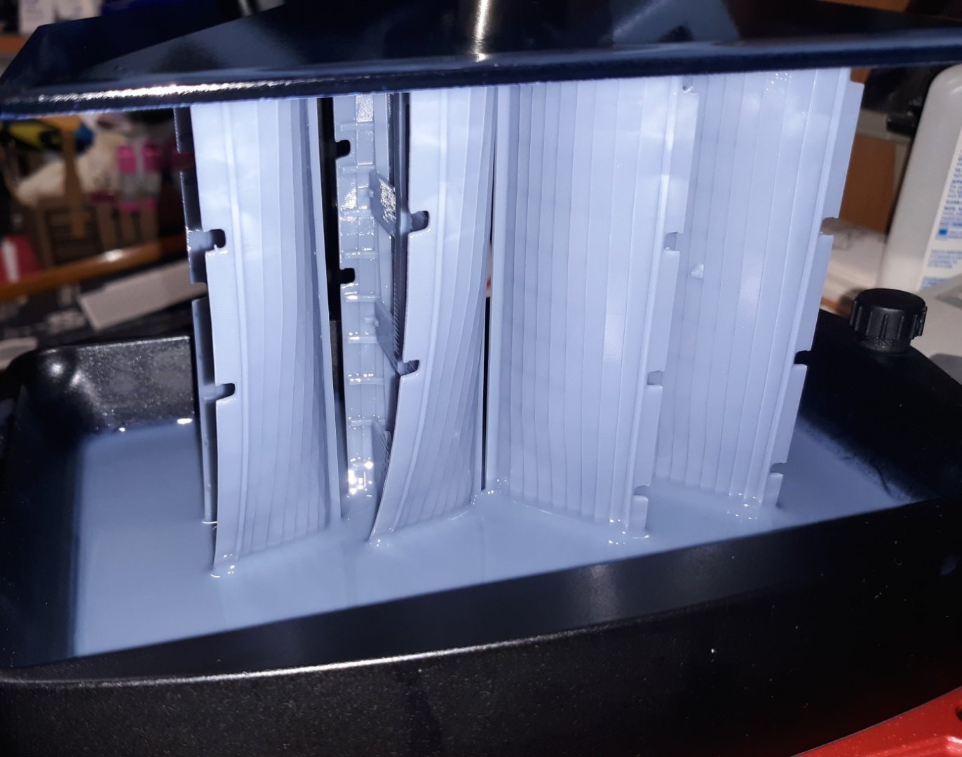
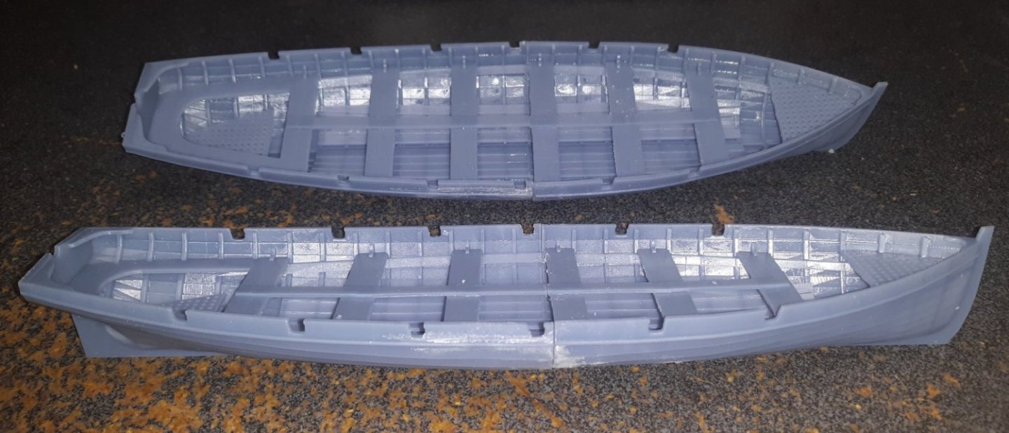
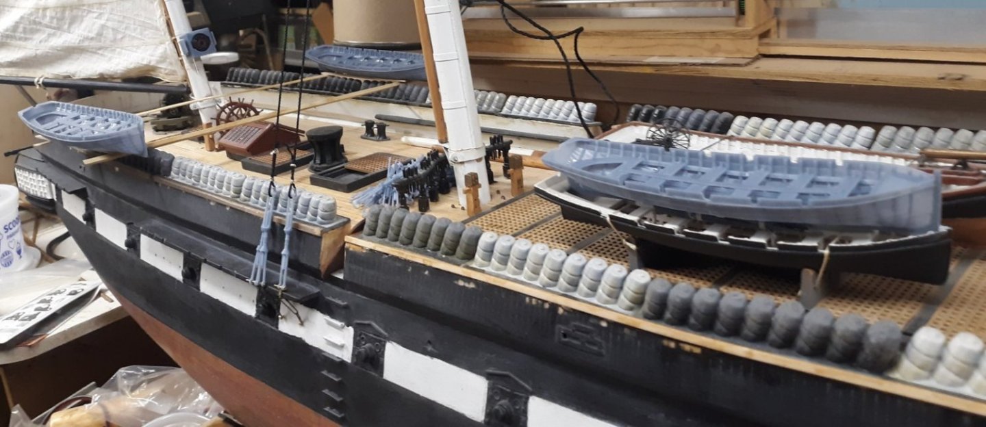
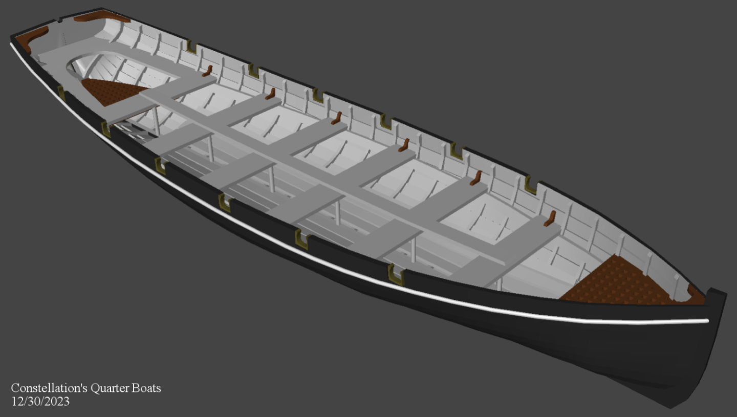
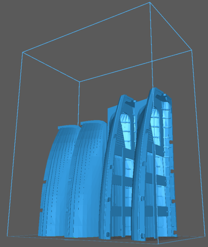
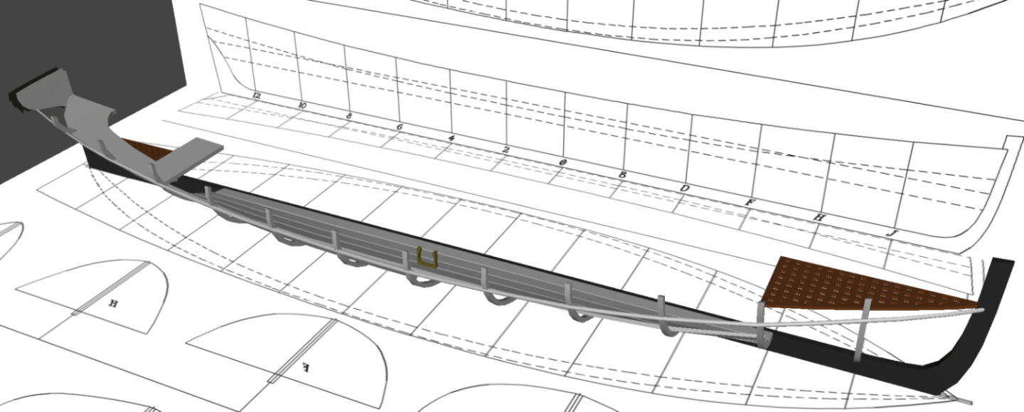
The quarter-boat was built a little "heavier," learning from the 2nd cutter. A lot of parts from the cutter were copied into the QB and adjusted to fit, until it was ready to be mirrored into a whole boat and printed. In the slicer software the blue box outline shows the volume the printer can handle. There was no trouble printing two copies of the boats at once. Like the cutter, the two halves are bonded together by wetting the seam with resin and zapping it with UV light. The seam needs some clean-up, just like any plastic model. Here's all three boats on the model where they'll be stationed eventually. Now it's on to the stern boat...


- 524 replies
-
- 4
-
-
- sloop of war
- constellation
- (and 3 more)
-
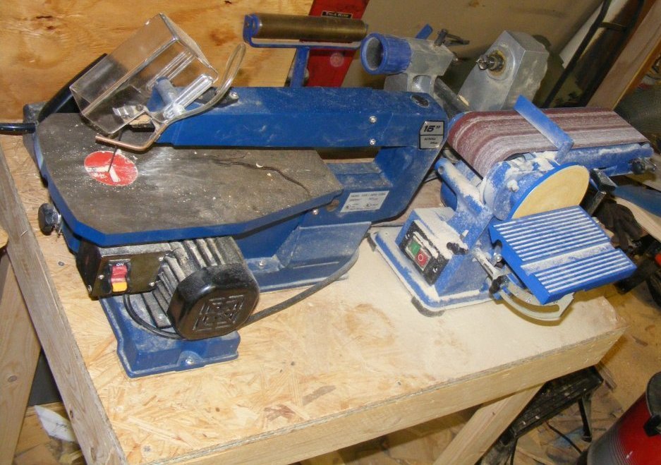
I have one of those Harbor Freight belt/disk bench sanders. I needed a lot of tightening and adjustment at first, and is due for some of that again, but it does the job for modeling just fine. It's a bit weak for cabinet work though. The biggest drawback with these "cheap" sanders is the table in front of the disc - they tend to be weak, unstable, floppy, and inaccurate. Mine would always creep onto the disc until it ate the edge off, no matter how much I tightened it. Basically, unless you're ready to practically rebuild the tool, stay away from the very "cheap" one, cause they are very cheap. It's to the right in the pic
-
Welcome aboard Chuck, from about an hour away from you in Maryland.
-
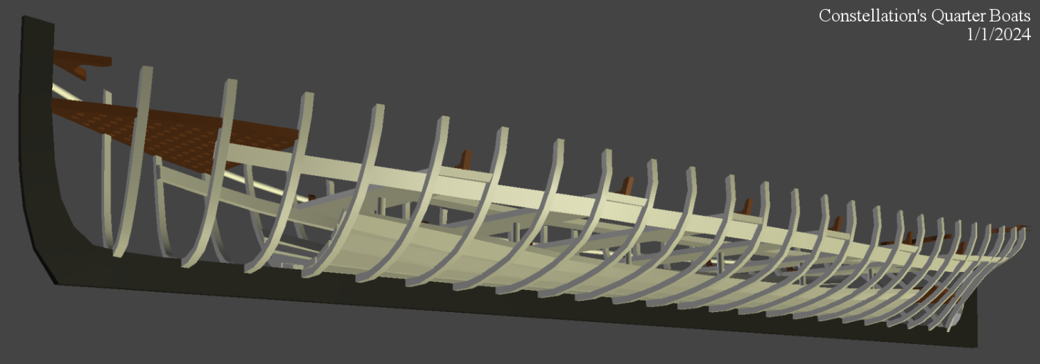
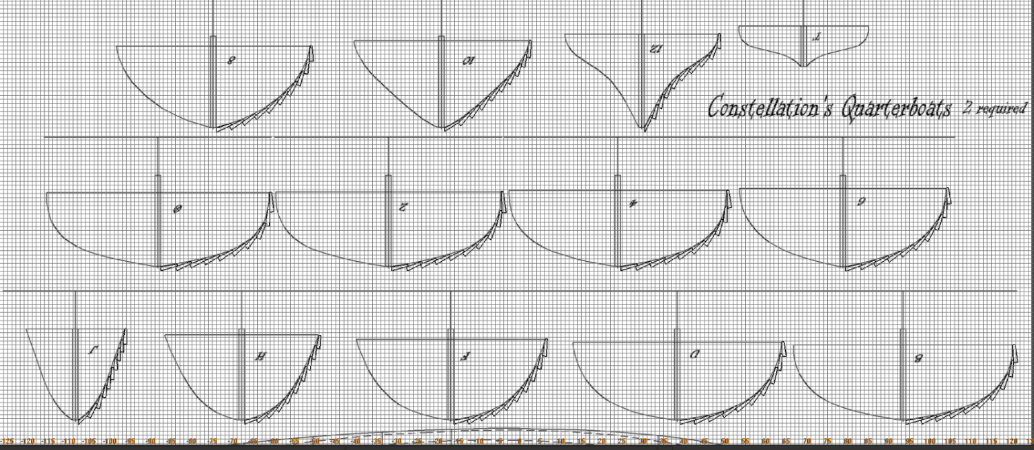
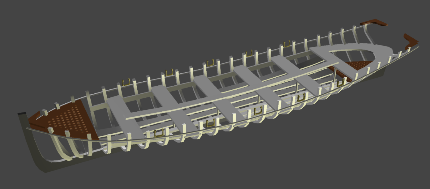
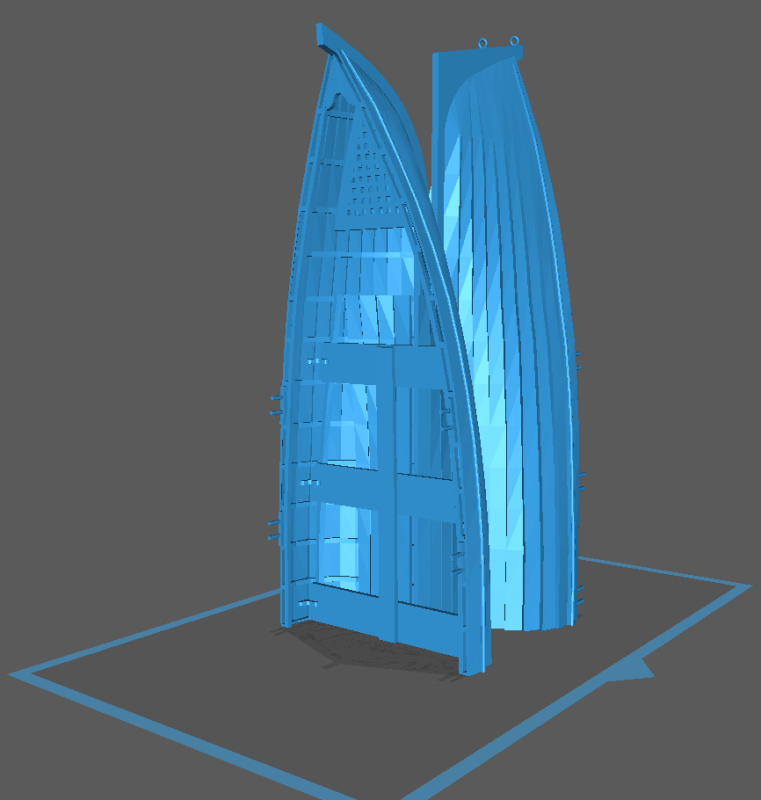
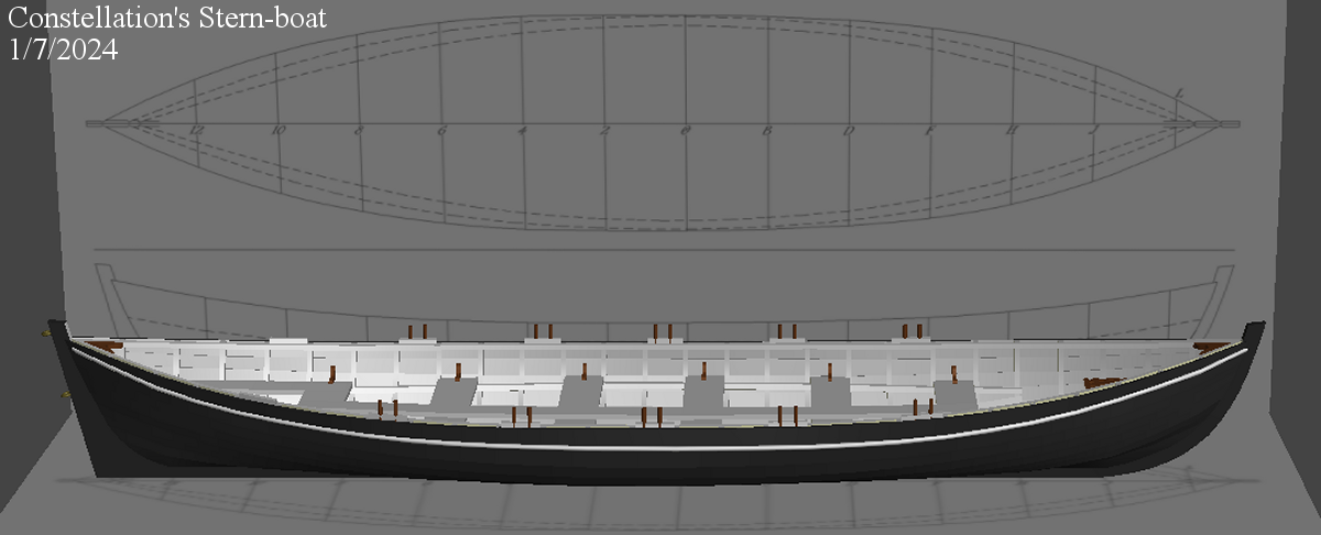
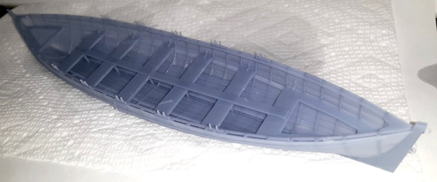
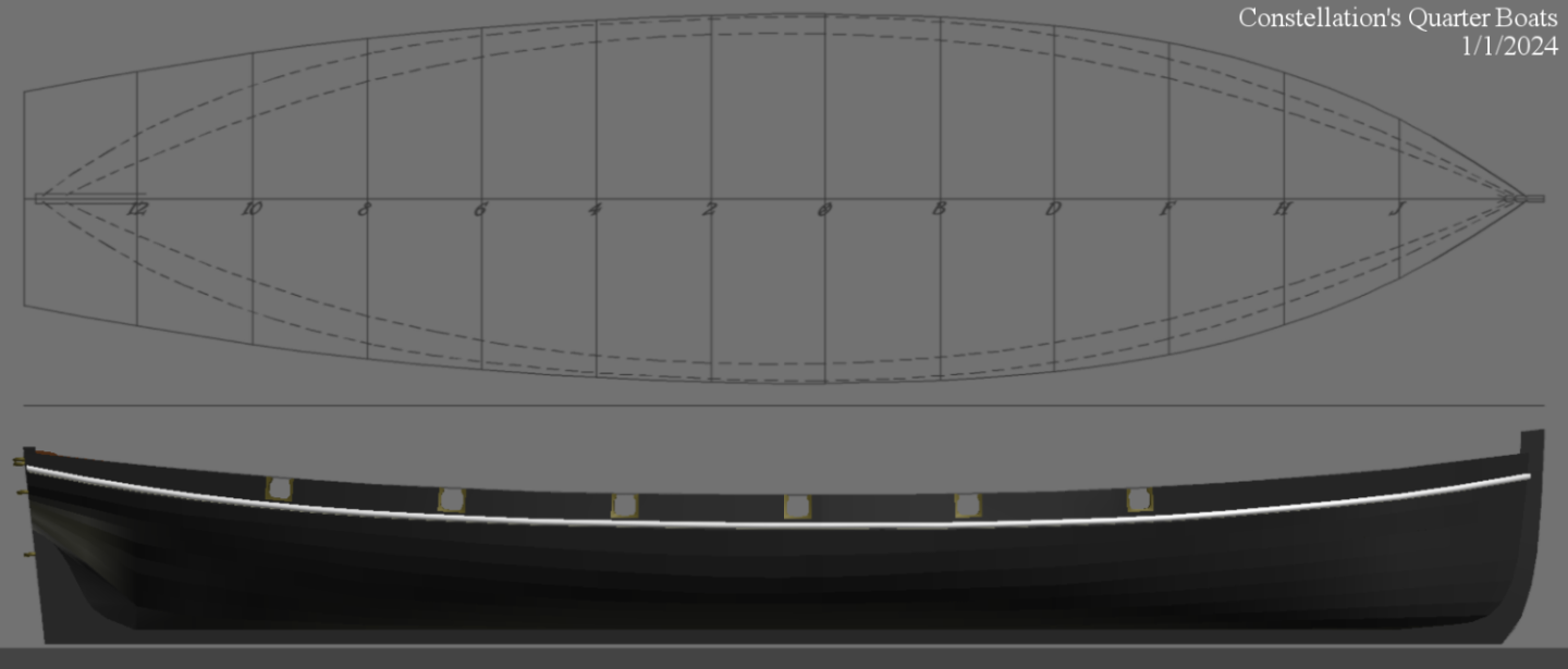
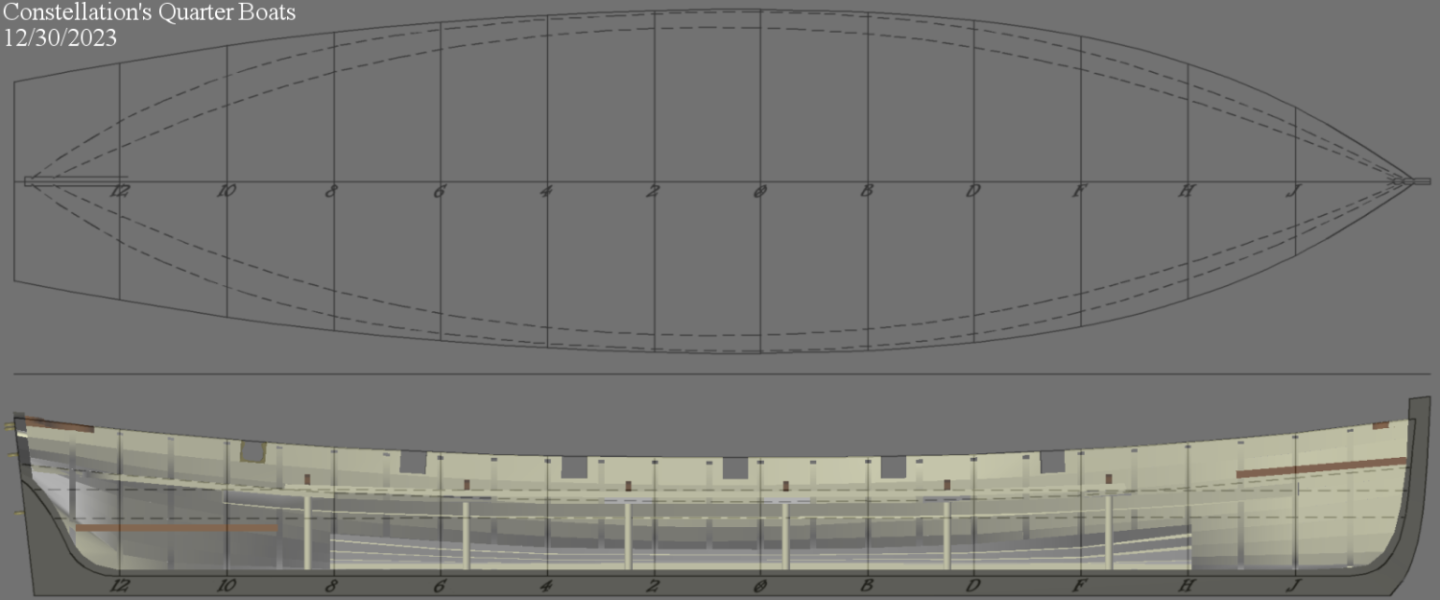
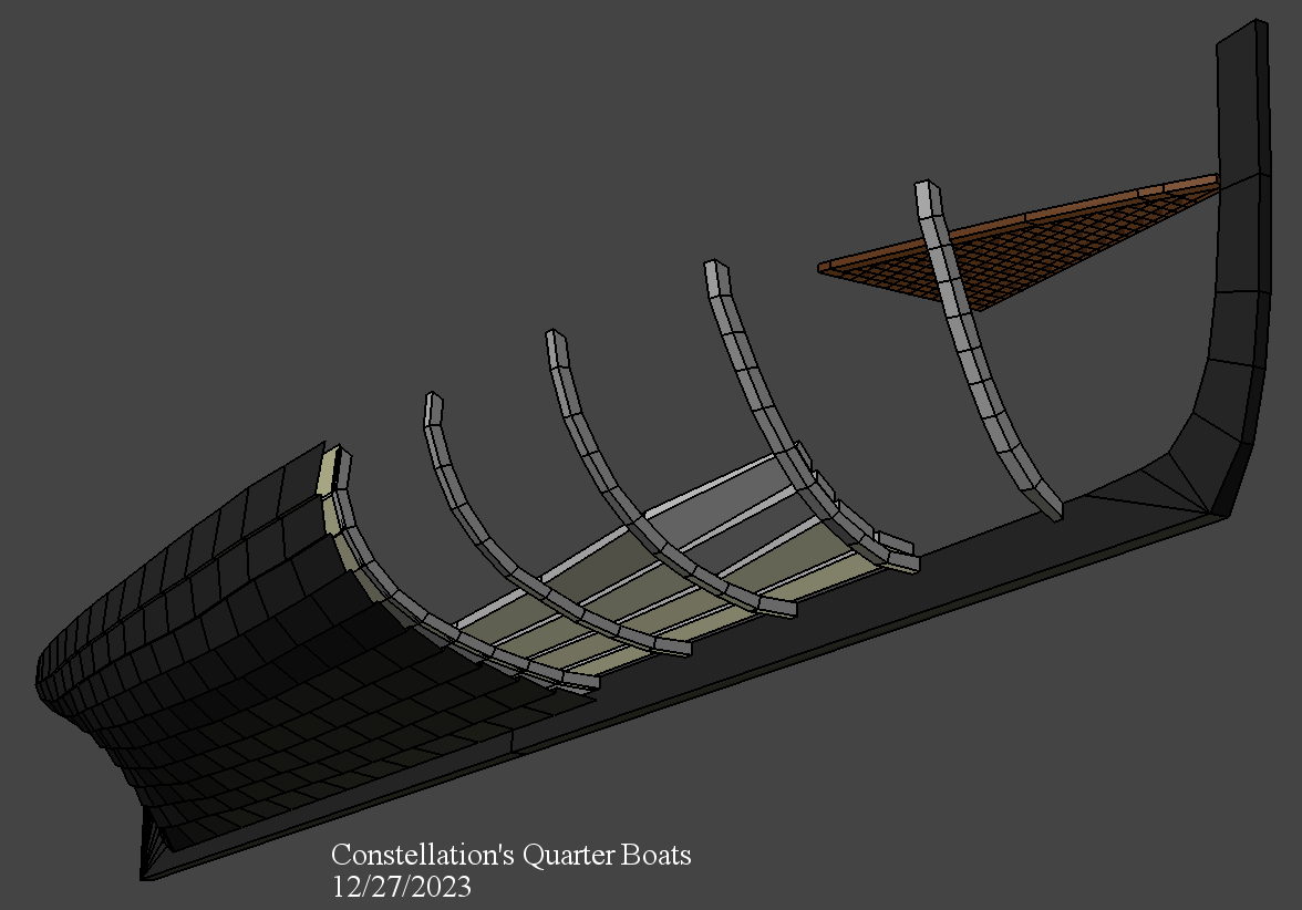
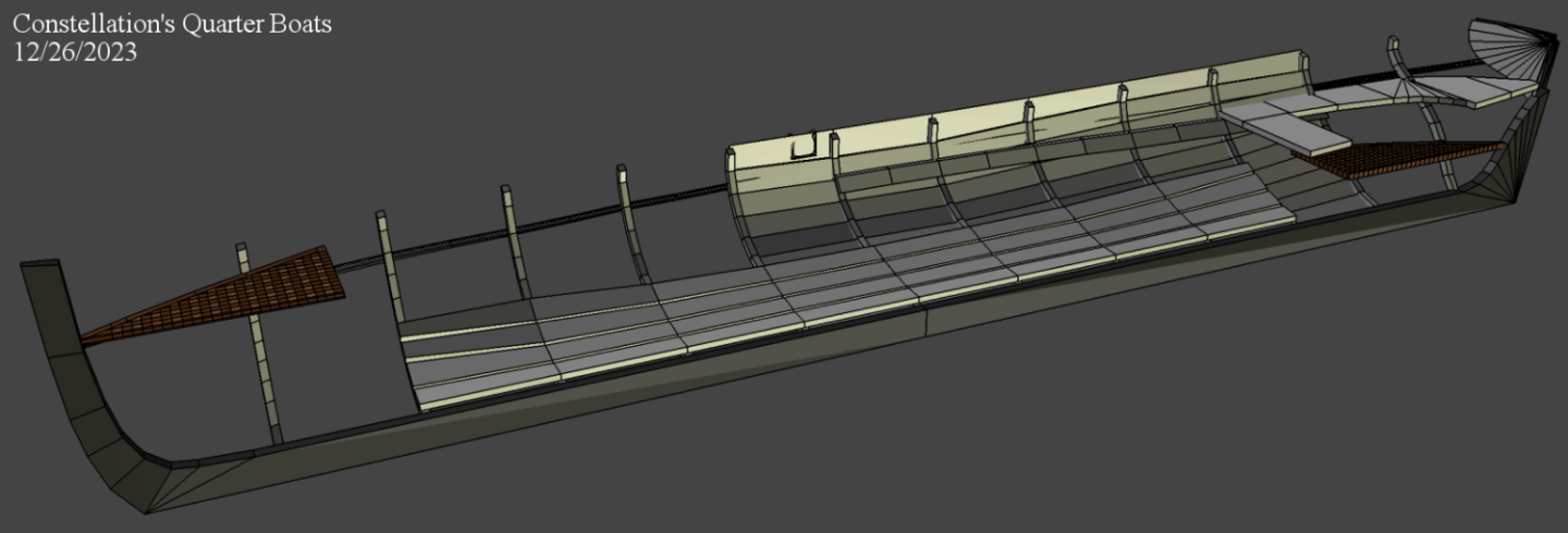
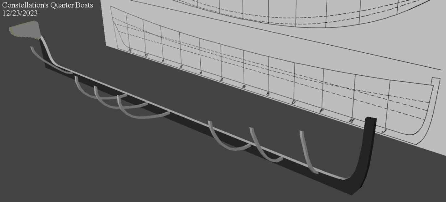
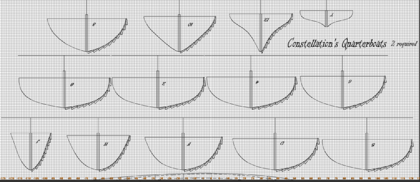
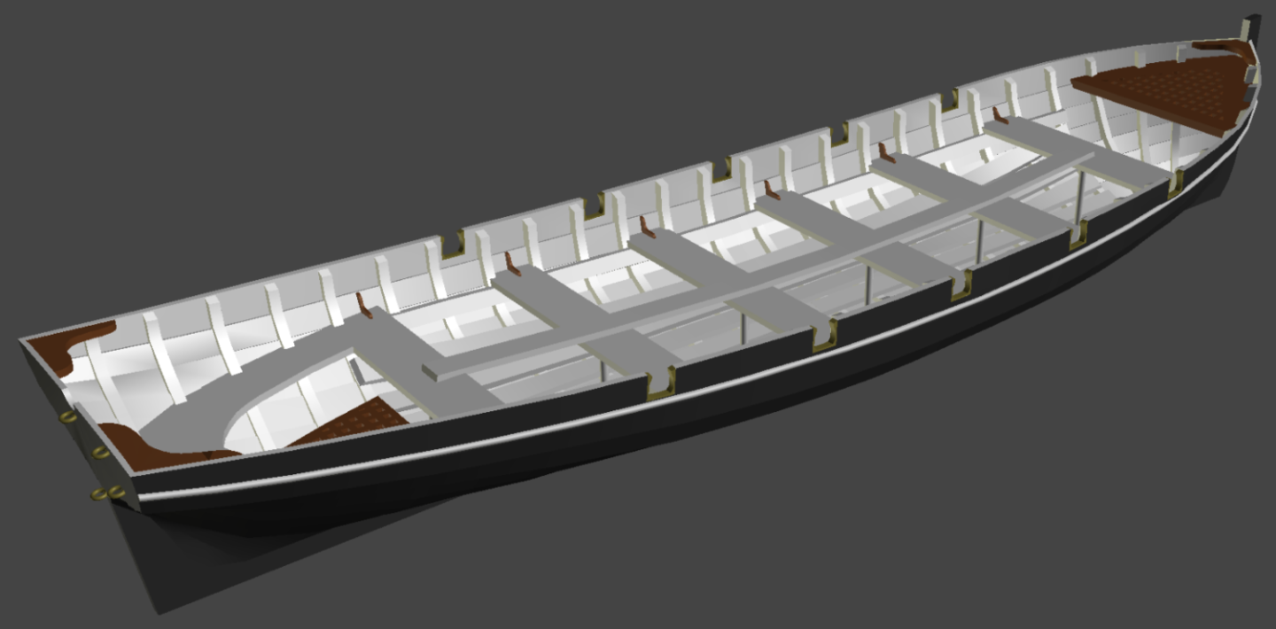
As with everything I do, this isn't "how to do it" but how I did it. It's not necessarily the right way, best way, or easiest way, just the way I'm doing it; which, by-the-way, is different from how I did the last boat. That said... I tossed out the quarter-boat from a couple of posts ago, except for the keel, and started over. I made a wire-frame cross-section of a single plank 4mm wide, 1mm at the thick end, .5mm at the thin end, and the part's rotation point on the inside edge .5mm from the thick end. I copy-and-pasted each profile around each station after adjusting it's length to make 10 of them fit in the length of that station, and rotating it so it's top touched the station line. I wound up with what's in the picture. Once this was set-up, I started making the ribs. Each rib is 1 x 1mm and in 10 segments to match the planks. I set each one up on the keel as it was made. Part of each plank will be buried in the rib giving the impression that the rib is cut to fit the insides of the planking-it's not. When I had the ribs represented by station lines, and the transom set-up, I started copying some parts of the 2nd cutter over, and adjusting them to fit the quarter-boat; such as stern-seats, gratings, floor-boards, seat-clamp, rub-rail. Some of this will need further adjusting once the inside planking shell is in place. To make the "planking" or more properly the inner shell of the hull, I traced the planking profiles described above to get a zig-zag wire-frame of the inside of the planking. This is placed at it's station and matched up with it's rib, already in place. When the second once is placed I can join the two as a single part, and connect the dots making a wire-frame of that section of planking between those two stations. The wire rectangles are made into surfaces which will face the inside of the boat, as this is the inside surface of the planking we're making here. as you may have noticed, this is all quite tedious, but it's much more precise that how I did the cutter while not being any more work; it's actually a little easier on the brain, which is also helped by my figuring out Anim8or's layers function. As with the cutter, I only need to make the starboard side of the boat. Once that's all adjusted to fit, I'll mirror them to the port side to get the whole boat. Meanwhile, I'm trudging along making the the inner planking surface. Then I'll basically repeat all the for the outer planking surface. A lot gets adjusted to the inner surface, and keeping the outer surface as a separate part let's me hide it so I can see things relative to the inner surface. That way there's no little unseen gaps that could mess up the 3D print, like having the end of a seat not connected to anything, or something of that nature. Yes, the planking is flat between each station; once the inner and outer planking shells are done, I'll slice through them creating 1/2 stations which will give me another adjustment point to help smooth the hull. I may even slice it into 1/4 stations, since the more slices, the smoother the hull gets.

- 524 replies
-
- 2
-
-
- sloop of war
- constellation
- (and 3 more)
-
Fiber glass hull, cloth and resin help
JerryTodd replied to Riotvan88's topic in RC Kits & Scratch building
I use 4oz cloth I get from DuckWorks, they sell 30" and 60" by the yard -
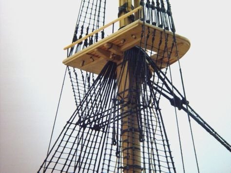
It depends mostly on the distance involved. If a man couldn't reach the top/crosstrees, from the shrouds, there would have to be rats on the futtocks. The larger the ship/rig, the more likely this will be, such on Victory here...
-
The Elegoo Mars 3, pictured in post #490. It's been really nice, right out of the box, though I've probably jinxed it now
- 524 replies
-
- 2
-
-
- sloop of war
- constellation
- (and 3 more)
-
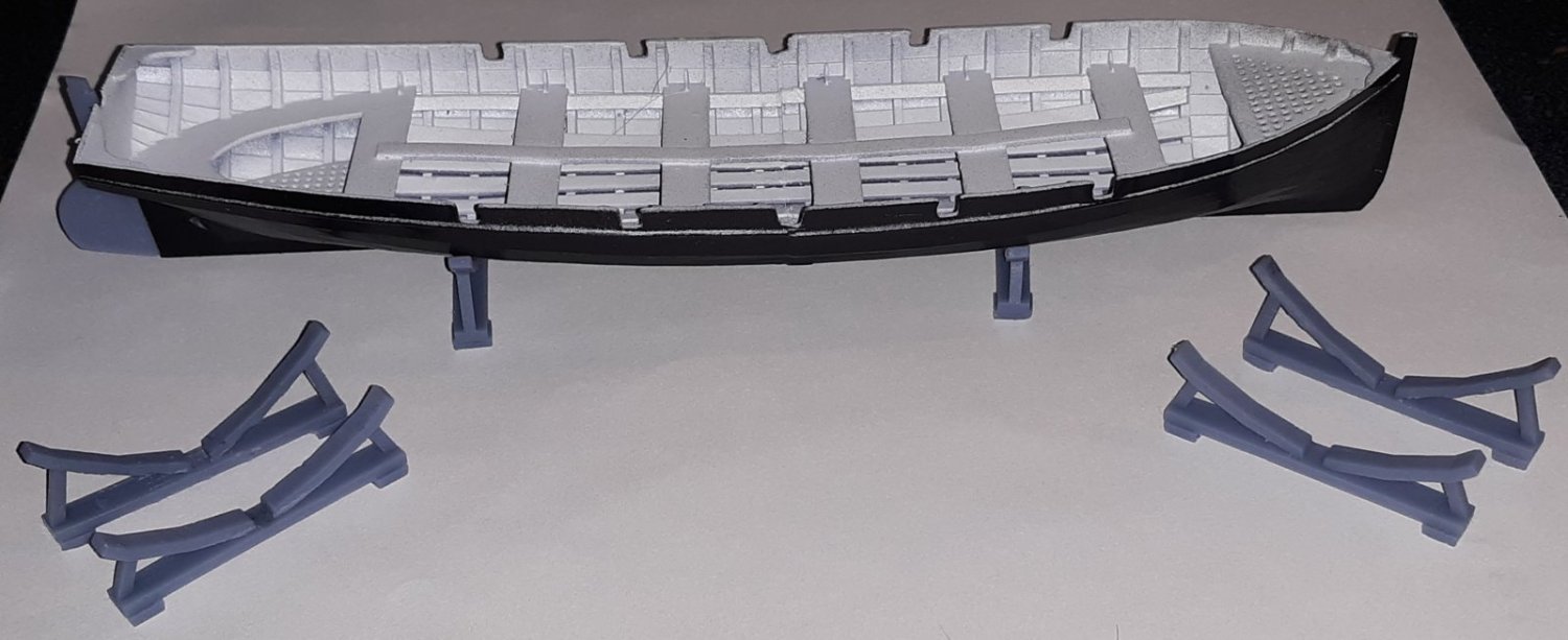
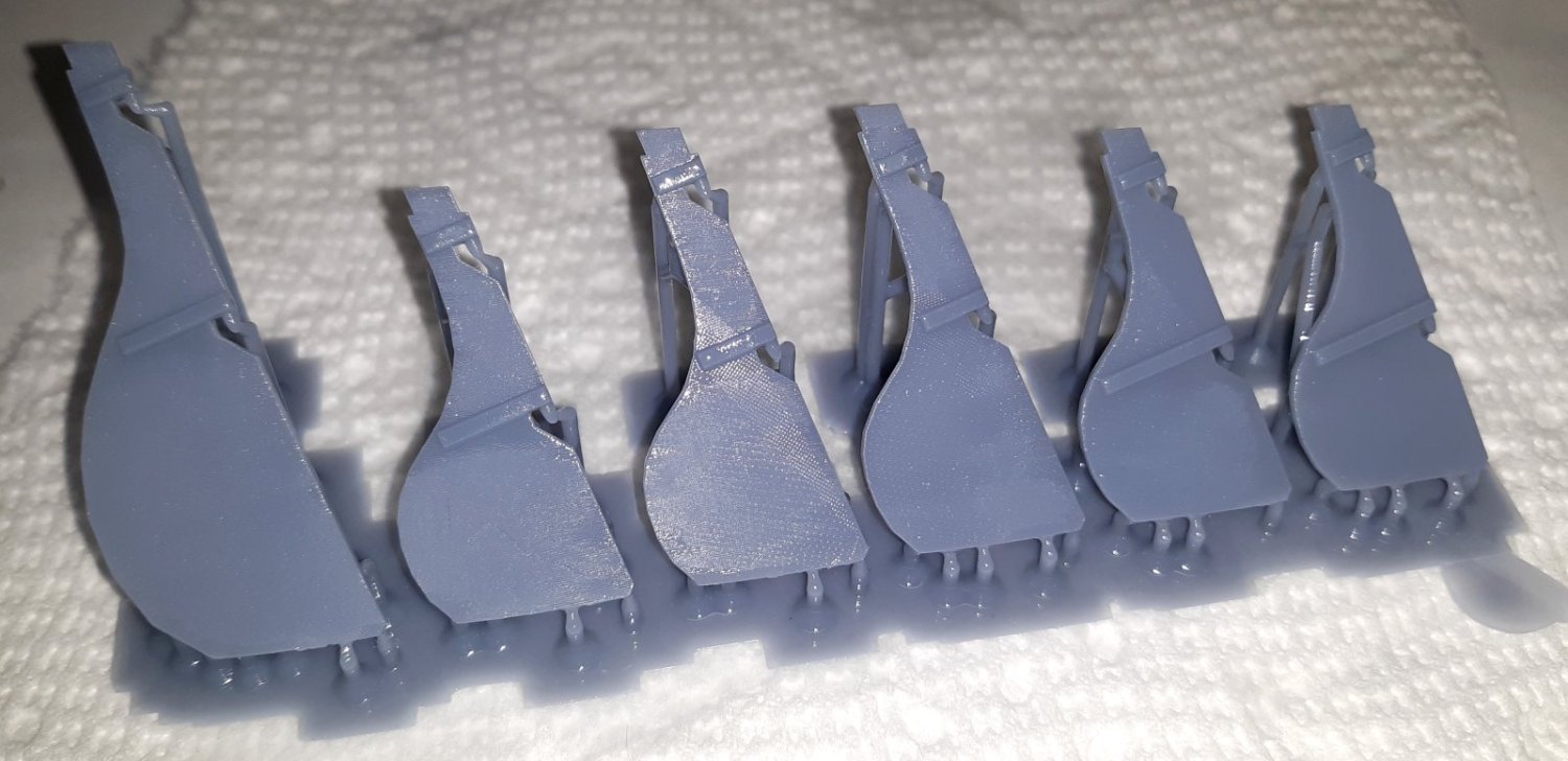
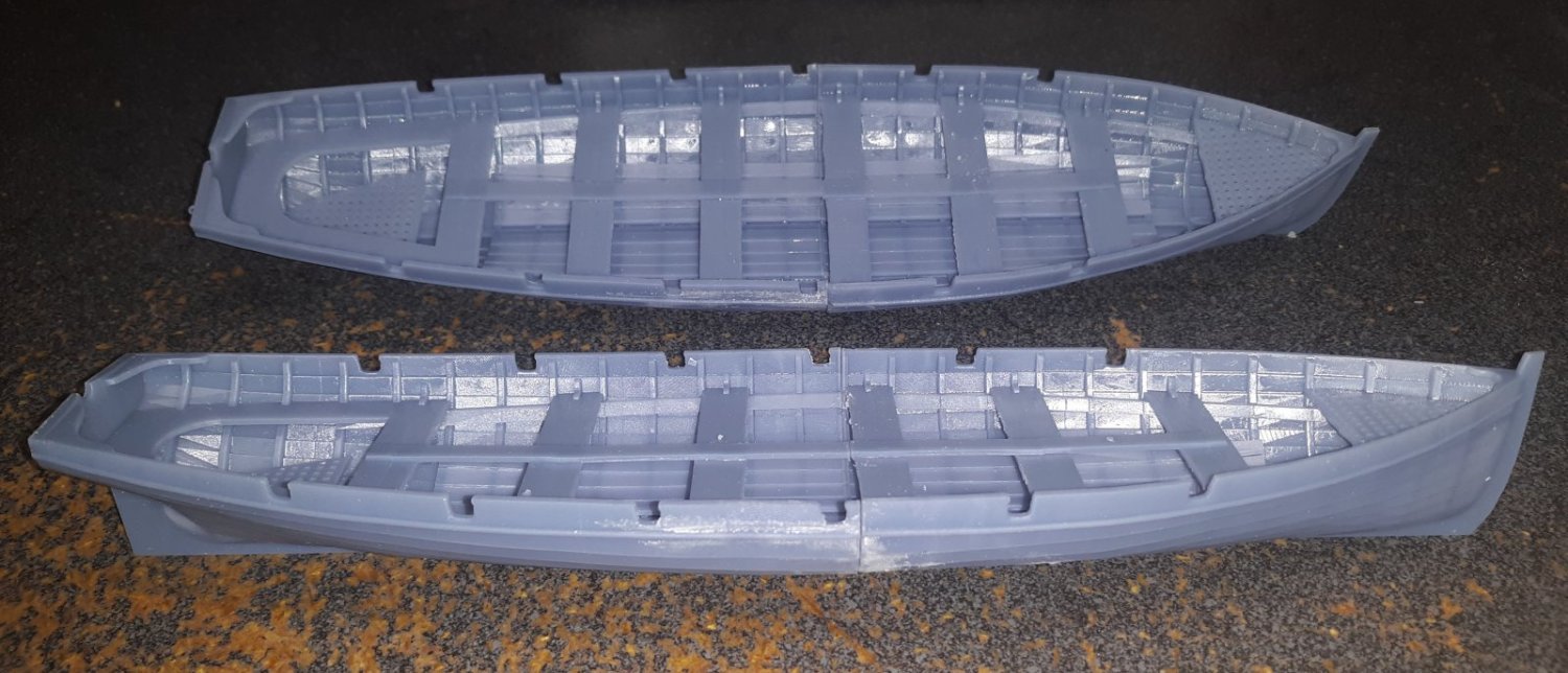
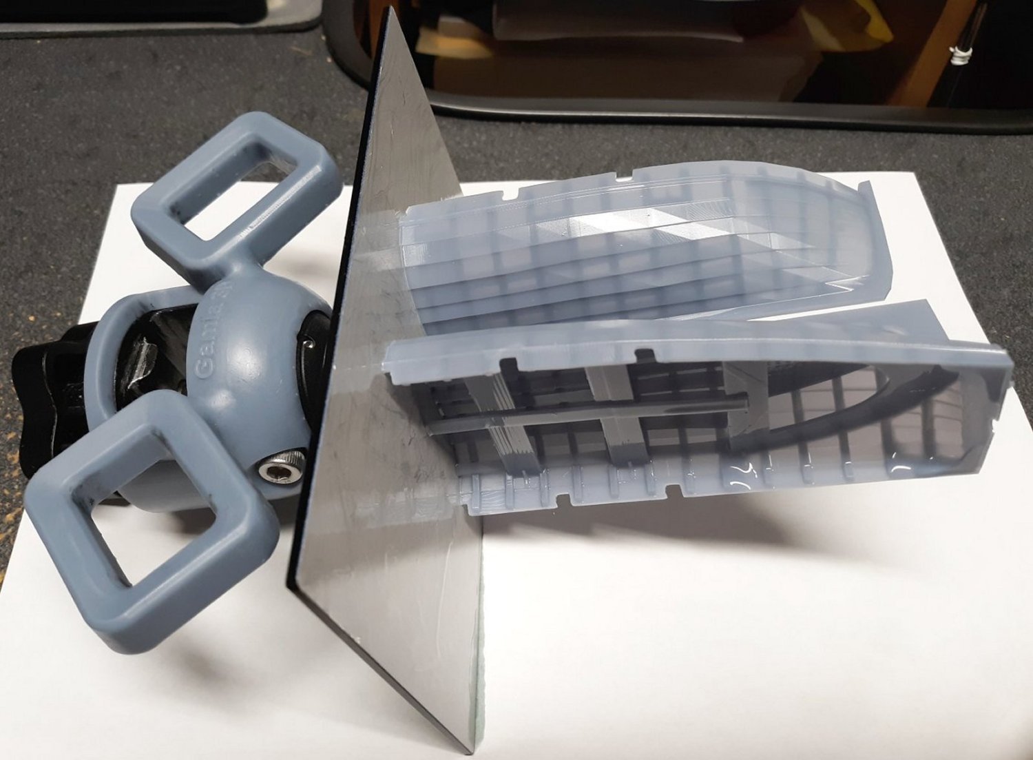
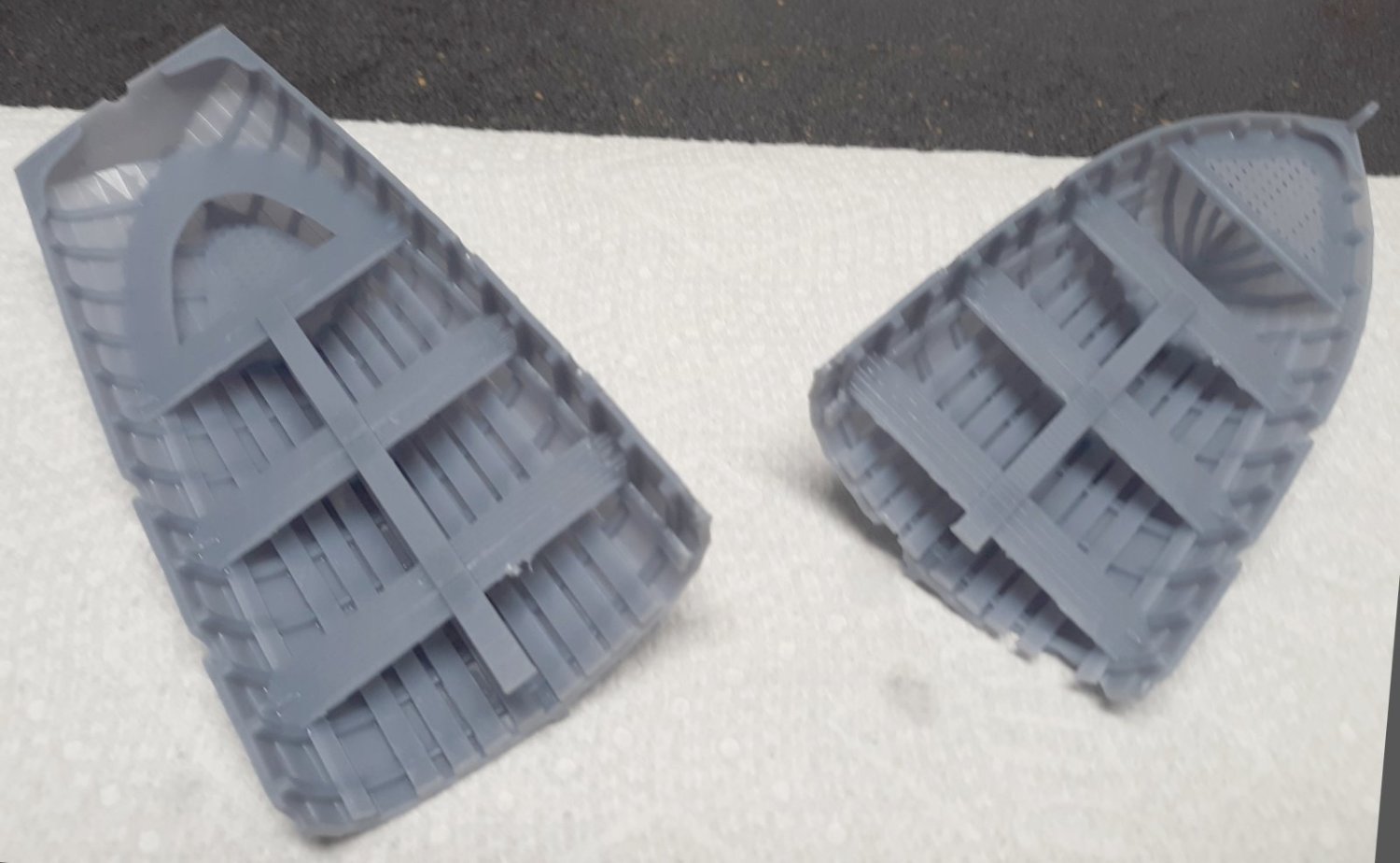
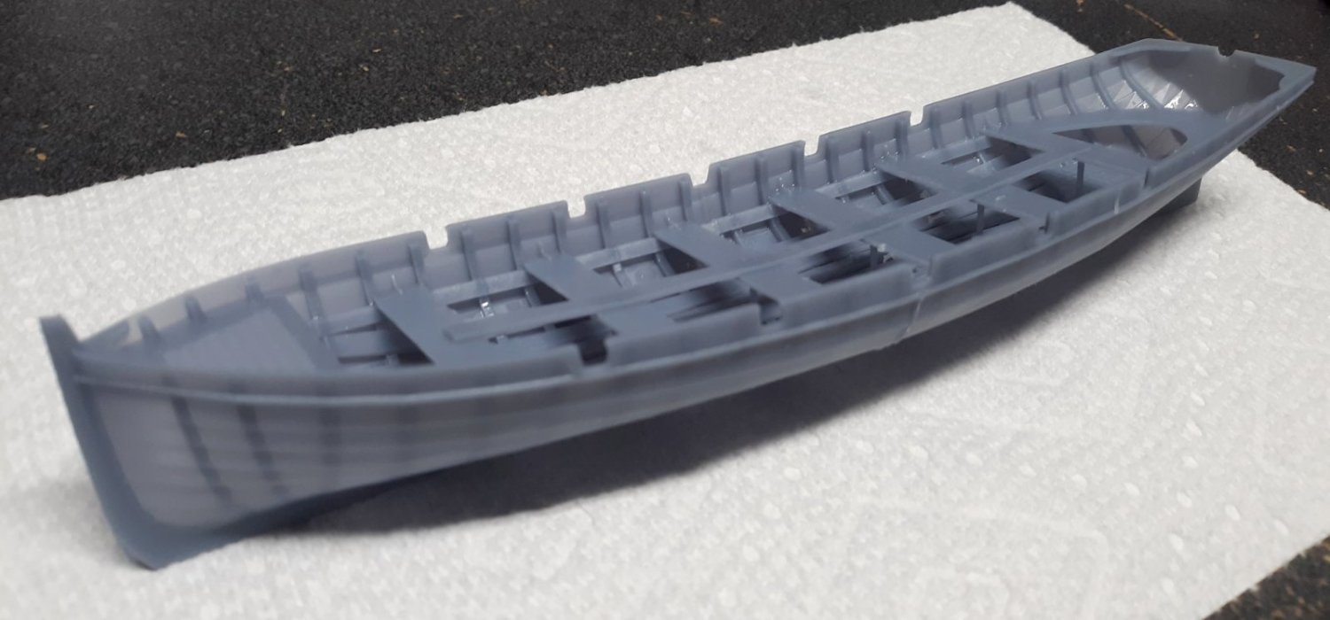
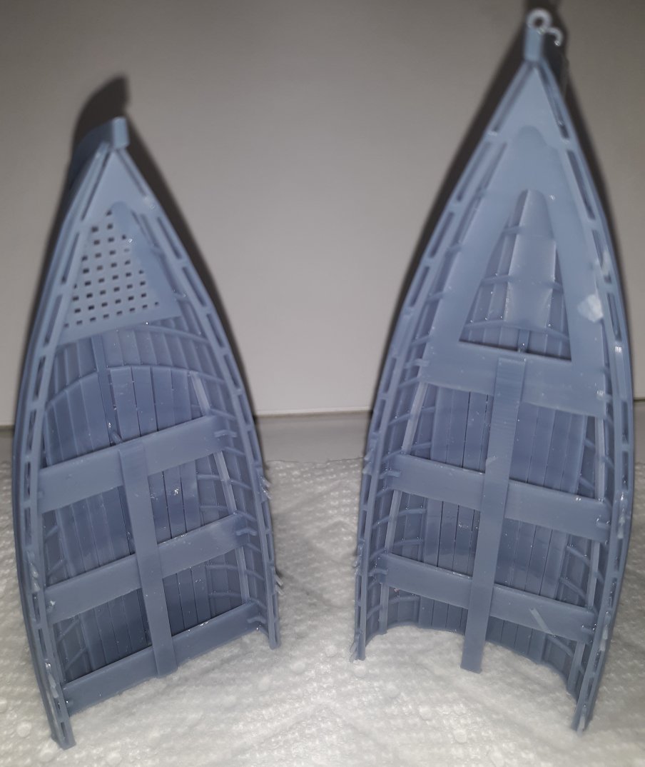
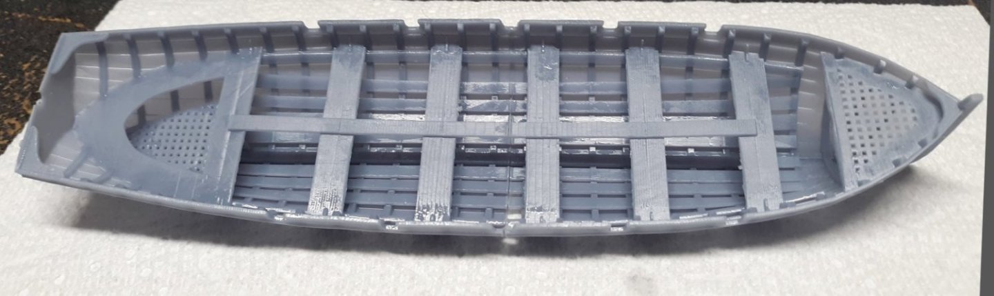
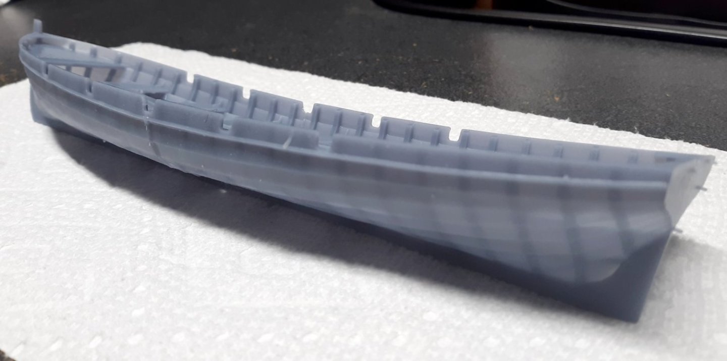
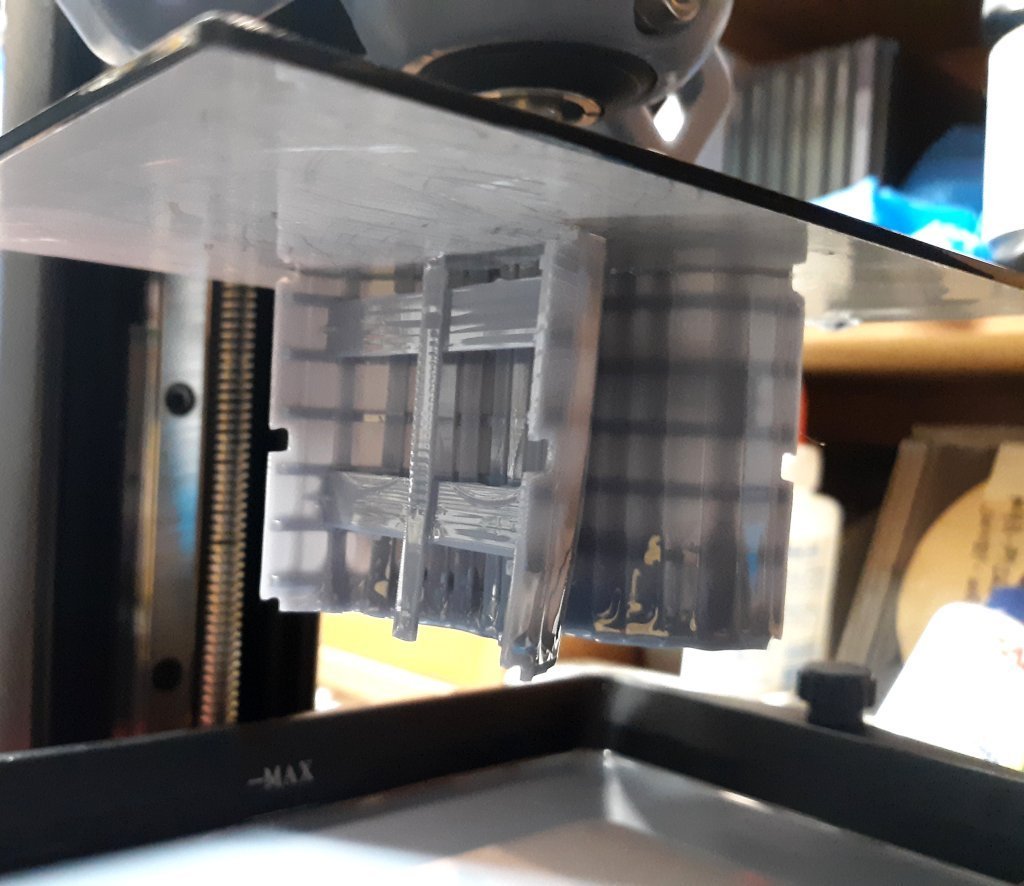
So it's printed! I was concerned the planking would be too thin, but it's fine, as long as the model isn't scaled down. Since I plan to share the file, I'll thicken some things up so it'll scale down to 1:96. I broke off a couple of chips from the bow section trying to get it off the plate, but that's easily repairable at the same time I bond the two halves together. The two halves are just sitting next to each other in these pictures. Once the halves are stuck together and the seam cleaned up, it's priming and painting time! This boat will sit on top of the 1st cutter, on the main hatch, which means making some chocks for it to print along with the oars, rudder, and other little things that'll go inside it.


- 524 replies
-
- 6
-
-
-
- sloop of war
- constellation
- (and 3 more)
-
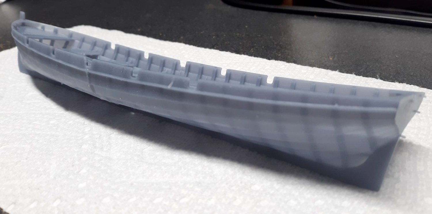
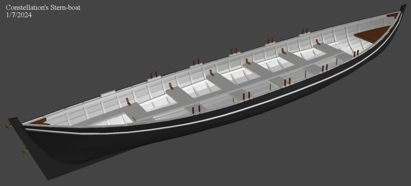
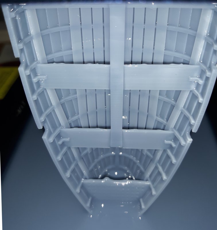
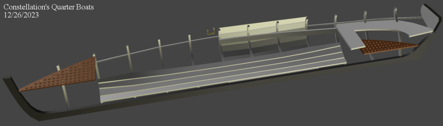
Getting the floor boards in was interesting, but in they went, four to each side; each in two parts; fore and aft; then all mirrored to the port side - so technically I only need to make parts for one side and mirror copy them to the other side. Each seat got knees on either side, and ring-bolts were placed on the transom, two for the rudder pin, and two for the flag. The inner and outer planking was "joined" and the gaps between them closed off, and it was "done." As I type this it's just at 50% printed (the pic was at 45%) and the planking is looking a bit thin. I'll see how it turns out, and if need by thicken the planking shell to 2mm and print it again. The slicer says it'll weight 29.9 grams (1.6 ounces), use $1.05 worth of resin, and take 4h 50m 57s to print.

- 524 replies
-
- 3
-
-
- sloop of war
- constellation
- (and 3 more)
-
I'm using stone tools compared to you Vic. Now, if I could figure out Blender, then I could finally do THIS kind of stuff!
- 524 replies
-
- 2
-
-
- sloop of war
- constellation
- (and 3 more)