
Supplies of the Ship Modeler's Handbook are running out. Get your copy NOW before they are gone! Click on photo to order.
×

JerryTodd
-
Posts
871 -
Joined
-
Last visited
Reputation Activity
-

 JerryTodd got a reaction from mtaylor in Constellation 1856 by JerryTodd - 1:36 scale - RADIO - First Class Sloop of War
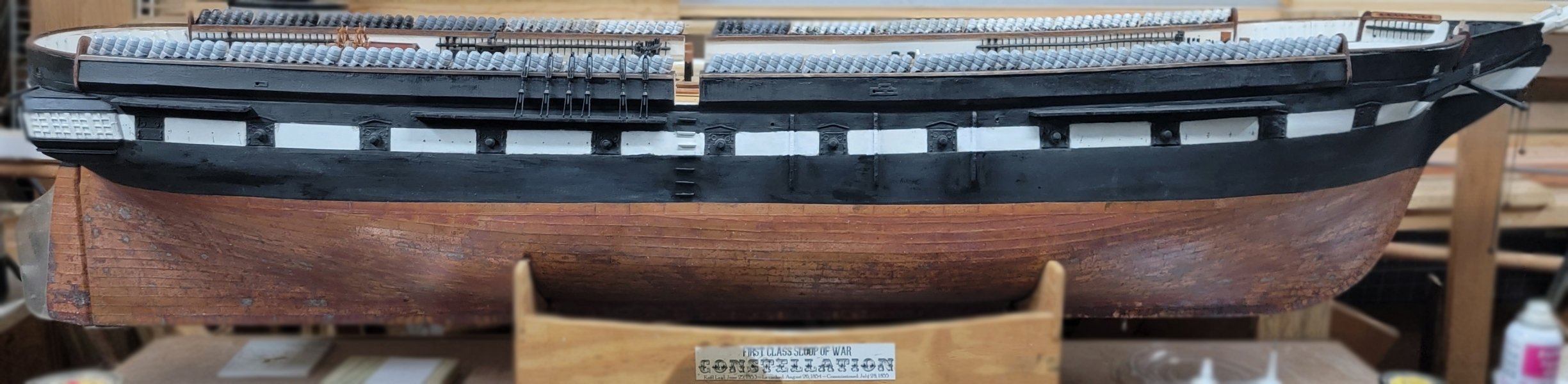
It's gotten too cold to pick up where I left off on Pride of Baltimore back in June, or even hang-out in the unheated shop for more than a few minutes; so I worked on 3D models for an item that's kind-of holding up starting on Constellation's rigging - pin-rails.
Here' the first attempt at the aft-most rails, which printed pretty fairly, though the left end of the upper one, and one of it's pins didn't do so well.
While that's repairable, when I modeled it, I forgot the bulwark it attaches to leans inboard a bit and forgot to model that angle on the back surface. Sanding that angle in would make the rail too narrow, so I'm fixing the 3D model and will reprint it.
The rails will be pinned to the bulwark where the wood blocks are inside it.
This pic shows how the bulwarks are constructed, as well as that inboard lean I mentioned.
-
 JerryTodd reacted to archjofo in La Créole 1827 by archjofo - Scale 1/48 - French corvette
Addition of the lifts of the lower yards - Balancines de basse vergue
Usually, as can be read in the specialist literature in the book "Manuel de gréement" by F. A. Coste, Paris 1829, the lifts of the lower yards were secured using tackles, each at the height of the 2nd shroud of the respective lower mast. This is also how J. Boudriot illustrated it in the monograph on La Créole, as shown below.
Source: Monograph La Créole by Jean Boudriot
On the original Paris model, I identified the lifts as shown in a diagram:
Source: Musée national de la Marine de Paris - La Créole
However, no tackles can be seen there. The lifts were simply attached to the upper part of the tackle ropes at the height of the 2nd shroud. This easier handling of the lifts could have been due to the size of the ship, or is it a simplification by the contemporary model maker?
We will never be able to find out.
However, I find this type of seamanlike handling of the lifts rather impractical and have therefore decided to use tackles, whose ropes can then be properly secured on the inside.
I wouldn't exactly describe my model as a "pile of evidence" as a dear forum colleague once described his project. However, I have implemented a large number of details on the model that seemed plausible to me after research. I cannot provide 100% proof of this, but solutions that actually existed and generally fit into the temporal and country-specific context of La Créole.
In this respect, I will basically attach the lifts as follows:
Source: Excerpt from Atlas du Génie Maritime annexe N.1, Pl. 20
However, I will only use a double block at the top and a single block at the bottom for the tackle.
To be continued...
-
JerryTodd got a reaction from mtaylor in Ships of the American Revolution
There are no kits of the 1797 frigate Constellation available, never have been.
-
JerryTodd got a reaction from mtaylor in Constellation 1856 by JerryTodd - 1:36 scale - RADIO - First Class Sloop of War
Half-an-hour-ish, and I've fFixed the pin-rail model to have the proper angle back-side, and set it to printing.
Five hours and some change later it came out perfectly. See the angle? Well there it is siting somewhere near where it will live.
While that was printing I started making the midships pin-rail; the one closest in this screen capture.
In this picture from the 1890's, I originally though there was a caval at the aft end, but it actually appears to be a pair of meat tenderizers.
This wasn't going to fit in the printer, even at an angle, so I made each side in two parts, and angled them (not to fit, but make them more likely to print properly)
As I type here, this one is on the printer with about 4 hours to go
Keeping with that workflow I should be making the forward pin-rails while the others print, but it's almost 3am, so, later...
-
JerryTodd reacted to archjofo in La Créole 1827 by archjofo - Scale 1/48 - French corvette
@albert
@64Pacific
Thank you for your interest and the nice comments, and thank you all for the LIKES.
Topsail-halyard traveller – Gouvernail de drisse
There was something else, wasn't there?
I have now made the missing 5 topsail-halyard travelers out of brass to complete the set.
To produce the guide rings required for this with a diameter of 1.5 mm (incorrectly indicated in the drawing as 1.2 mm) and with a bore of 0.8 mm, the modifications made (new electric motor with speed control and collets) to my Unimat SL served me very well.
I am currently sorting out the continuation of the lifts for the lower yards.
See you soon...
-
JerryTodd reacted to archjofo in La Créole 1827 by archjofo - Scale 1/48 - French corvette
A small update:
Completion: Topsail halyards
The tackles for the topsail halyards are now all rigged.
See you soon...
-
JerryTodd reacted to archjofo in La Créole 1827 by archjofo - Scale 1/48 - French corvette
@wefalck
Hello Eberhard,
I think it would not be a good idea to introduce the French (French publisher) to the rigging practices of the French Navy at the beginning of the 19th century for model making.
@Erik W
Hello Erik,
I'm pleased that my pictures, especially of the rigging work, are helping you with your model building.
As I also benefit a lot from pictures and construction reports from other model builders for my project, I want to give something back. It's a give and take that benefits model building as a whole and allows it to develop further. Ultimately, we all have great joy in the results that we have created with our own hands and can look at.
@dvm27
Hello Greg,
I'm happy to comply with your request.
Here is a picture with a ruler:
I used two methods to make the thimbles, although I actually only work with the simpler one.
I also make the thimbles in different diameters, depending on the requirements of the rigging.
Here are two places in my construction report where I report on the production of the thimbles:
LINK
LINK
-
JerryTodd reacted to dafi in HMS Victory by dafi - Heller - PLASTIC - To Victory and beyond ...
For the next level, I prepared the top mast shrouds. Even if Steel doesn't mention it explicitly, in most modern sources the foremost shroud is also dressed here, so that's what I decided to do. The sisterblock is also integrated between the two forward shrouds.
But first come the hangers / burton tackles ...
... then the sister blocks ...
... and everything in place.
Here you can see again the difference between the dressed and undressed shrouds. Unfortunately, in contrast to my self-made ropes, the purchased ropes do fluff a little, but this is not visible to the naked eye.
To continue working, I tensioned the shrouds down with clamps and gravity.
And dark ropes in front of a dark background are somewhat annoying even with good lighting, so I made a white cardboard template for this spot.
Here you can see again the difference between the dressed and undressed shrouds. Unfortunately, in contrast to my self-made ropes, the purchased ropes do fluff a little, but this is not visible to the naked eye.
To continue working, I tensioned the shrouds down again with clamps and gravity.
And dark ropes in front of a dark background are a bit annoying even with good lighting, so I made a white cardboard template for this spot.
Then the dead eyes were bound in as the lower ones. To compensate for the lack of a third hand, I then tied the shroud to be worked on with a thread to the yardarm, see green arrows, helps immensely.
XXXDAn
-
JerryTodd got a reaction from mtaylor in HMS Victory by dafi - Heller - PLASTIC - To Victory and beyond ...
This help?
The lanyard is hitched in the space between the bight of the shroud and the upper deadeye. That's what basically ties it off. the remaining is given a few wraps around the shroud, and the tail seized to it just to do something with the loose end. There's good chance of a lanyard breaking or being cut on a warship, and having that excess can save time in repair, not to mention the method of taking up tension on them requires a bit of length to set up.
I'm sure Victory was kept very prim and proper, being an admiral was aboard
At least you didn't do this...
-
JerryTodd reacted to dafi in HMS Victory by dafi - Heller - PLASTIC - To Victory and beyond ...
After the fighting top had found its place, it was finally time to fit the futtock shrouds.
The work preparation was the blackening of the etched parts and the painting of the dead eyes. Then the irons of the dead eyes were bent open, the dead eyes inserted and everything squeezed shut and secured with some glue.
The upper hooks were then tied into the shrouds. This shroud was fully dressed, again using my technique with white glue as for my scale.
First test of the dead eyes in the holes of the fighting top and the shrouds hooked in.
Now you can see where the holes in the fighting top need to be reworked so that the irons don't sit at an angle. The lower shrouds have also been marked with a thread to hold the futtock shrouds.
Next, the dressing of the lower shrouds was completed and brought to the same height.
Finally the futtock shrouds could be hooked in, wrapped once around the futtock stave and tied to the shroud.
After trimming, this is what came out http://www.shipmodels.info/mws_forum/images/smilies/icon_smile.gif
XXXDAn -
JerryTodd reacted to archjofo in La Créole 1827 by archjofo - Scale 1/48 - French corvette
@Thukydides
@davyboy
@jdbondy
@Mike Y
Your praise and your kind words encourage me in my work.
Thank you for that and thank you to the others for the LIKES.
Continuation: Additional accessories for the topsail halyards - swivel hooks
In the meantime, I have made all 6 swivel hooks for the topsail halyards. The length for the main topsail yards and fore topsail yards is 8.2 mm. The swivel hooks for the mizzen topsail yards were proportionally made a little smaller (L = 6.9 mm).
I tried to make these hooks based on a drawing in the Atlas du Génie Maritime.
Source: Excerpt from Atlas du Génie Maritime annexe N.1, Pl. 2
Here, with this photo montage, I would like to illustrate the individual production steps.
To conclude this short update, the finished, blackened hooks.
See you soon...
-
JerryTodd reacted to archjofo in La Créole 1827 by archjofo - Scale 1/48 - French corvette
Continuation: Further accessories for the topsail halyards, including leader (guide bar) - Gouvernail de drisse
The leaders are another accessory required for the topsail halyards. This is a detail that is not always visible on all models, but is an important part of the rigging.
Under the considerable force required to set a topsail, the halyard tends to twist and become unclear. To prevent this, the upper halyard block was guided to the topmast backstay with a guide bar and a swivel hook was used at the channel.
In the following, I have compiled a list of different types of guide bars that were used towards the end of the 18th century and in the 19th century. However, they all served the same purpose.
For my model of La Créole, I naturally used the original Parisian model and the Manuel du Gabier. Compared to the original model, however, I added the swivel hook and made a longer strop, which made it possible to keep the lower block free of the bulwark and the tackles of the backstays.
I then executed this rigging arrangement according to the following drawing.
I made all the elements in advance to see how it would look overall. If the “prototype” fits, all the other necessary parts for all the topsail halyards will be made.
Provisionally arranged, it then looks like this:
I had already made the swivel hooks in connection with the stay tackles, so that went quickly. Making the guide bar was also not a big job. For the sake of strength, I hard-soldered all the connections of these components.
It was a little more difficult to attach the guide bar to the topsail halyard. It would be unsightly if over-dimensional knots were to impair the filigree structure.
I have already considered how I can then attach the halyard to the model. In this respect, I have to finish one side completely as shown and then serve the appropriate places in advance, such as the passage through the tye blocks and the other end of the halyard. Then the rope of the topsail halyard is pulled through the tye blocks, then the eye with thimble is completed, taking the upper block into account. Finally, I have to dress a short remaining section freehand and attach the guide bar.
Certainly not an easy task on the model, but people also need certain challenges ...😊
To be continued ...
PS: I don't know if the term "guide bar" is correct?
I would be grateful if someone could tell me the correct term.
-

 JerryTodd got a reaction from Snug Harbor Johnny in HMS Victory by dafi - Heller - PLASTIC - To Victory and beyond ...
This help?
The lanyard is hitched in the space between the bight of the shroud and the upper deadeye. That's what basically ties it off. the remaining is given a few wraps around the shroud, and the tail seized to it just to do something with the loose end. There's good chance of a lanyard breaking or being cut on a warship, and having that excess can save time in repair, not to mention the method of taking up tension on them requires a bit of length to set up.
I'm sure Victory was kept very prim and proper, being an admiral was aboard
At least you didn't do this...
-
 JerryTodd got a reaction from popeye2sea in HMS Victory by dafi - Heller - PLASTIC - To Victory and beyond ...
This help?
The lanyard is hitched in the space between the bight of the shroud and the upper deadeye. That's what basically ties it off. the remaining is given a few wraps around the shroud, and the tail seized to it just to do something with the loose end. There's good chance of a lanyard breaking or being cut on a warship, and having that excess can save time in repair, not to mention the method of taking up tension on them requires a bit of length to set up.
I'm sure Victory was kept very prim and proper, being an admiral was aboard
At least you didn't do this...
-
 JerryTodd got a reaction from BLACK VIKING in HMS Victory by dafi - Heller - PLASTIC - To Victory and beyond ...
This help?
The lanyard is hitched in the space between the bight of the shroud and the upper deadeye. That's what basically ties it off. the remaining is given a few wraps around the shroud, and the tail seized to it just to do something with the loose end. There's good chance of a lanyard breaking or being cut on a warship, and having that excess can save time in repair, not to mention the method of taking up tension on them requires a bit of length to set up.
I'm sure Victory was kept very prim and proper, being an admiral was aboard
At least you didn't do this...
-
 JerryTodd got a reaction from Mexspur in HMS Victory by dafi - Heller - PLASTIC - To Victory and beyond ...
This help?
The lanyard is hitched in the space between the bight of the shroud and the upper deadeye. That's what basically ties it off. the remaining is given a few wraps around the shroud, and the tail seized to it just to do something with the loose end. There's good chance of a lanyard breaking or being cut on a warship, and having that excess can save time in repair, not to mention the method of taking up tension on them requires a bit of length to set up.
I'm sure Victory was kept very prim and proper, being an admiral was aboard
At least you didn't do this...
-
JerryTodd reacted to dafi in HMS Victory by dafi - Heller - PLASTIC - To Victory and beyond ...
This was the last stand, the deadeyes tied into the shroud and the lanyards threaded in but still loose.
The next step was to pull the lanyards through over the deadeye and under the shroud eye. I always use a threader from my sewing supplies, it's simply the best help for this.
Then, when wrapping the lanyard around the shroud, pass it under the last row of yarn from the deadeye, so that it clamps itself, then make 5 more turns and tie the end to the shroud.
Yay, another milestone victory!
As my shrouds are slightly elastic, I also used this to adjust the upper deadeyes a little when tensioning the lanyards. I don't like it completely leveled anyway, as you can also see in the originals and in contemporary models that the different elasticity of the manually made ropes leads to different lengths of the shrouds when tensioning, and thus to slightly varying heights of the deadeyes.
XXXDAn
-
JerryTodd reacted to archjofo in La Créole 1827 by archjofo - Scale 1/48 - French corvette
Continuation: Making more blocks - topsail halyards
As already mentioned, there are still a few blocks to be made, including for the topsail halyards.
Source: Monograph on La Créole by Jean Boudriot
I made these single and double blocks again using the method shown so far. This method is not the most effective and has little to do with series production, but I am quite happy with the result.
In the next step I will complete the tackles of the topsail halyards (strops, ropes, hooks, eyebolts, spacers, etc.).
See you soon...
-
JerryTodd reacted to archjofo in La Créole 1827 by archjofo - Scale 1/48 - French corvette
Hello colleagues,
Thank you in advance for your kind feedback.
When I started the final rigging, I was a bit too optimistic...😁
Making more blocks for tackles for truss pendants, redirecting the braces, bowlines, etc.
Before I take the model out of the dust cover as announced and start the final rigging, I thought that it would be more clever to make the missing blocks so that I can then make the craft room dust-free.
This required a lot of research to get some clarity about various design details.
In particular, it was about making the tackles for the truss pendants of the lower yards. The truss pendants themselves are already attached to the lower yards. Later, when attaching the lower yards, the ends of the truss pendants have to be guided through the sheaves on the trestle trees. Then thimbles have to be tied into the ends, to which the rope tackles can then be hooked. This drawing from the Atlas de Génie Maritime illustrates the principle.
Source: Extract from the Atlas du Génie Maritime Pl. 23
These tackles and other blocks with corresponding strops and thimbles, depending on the use, can be seen in the following picture.
Some time ago I also made a series of guide blocks, as shown below, which are hooked into the area of the belaying pin rails.
Accordingly, there shouldn't be too many blocks missing now. So I will now look through the rigging again using the monograph in conjunction with the pictures of the original model that I have available in order to capture as many blocks as possible. The tackles topsail halyards spring to mind and there are certainly still some deflection and guide blocks missing from the upper rigging.
With regard to the final rigging, I am wondering how the standing parts of the braces are correctly attached to the stays. There is certainly a specific way of attaching them (knots, banding, etc.). Unfortunately, I have not been able to find anything about this so far, neither in the specialist literature nor on the Internet.
I would therefore be very grateful if you could give me some advice.
To be continued...
-
JerryTodd reacted to dafi in HMS Victory by dafi - Heller - PLASTIC - To Victory and beyond ...
Slowly and carefully we went on, and then the time had come ...
... both sides of the deadeyes were integrated into the shrouds and tidied up. Final alignment of the deadeyes angle comes when I tighten the lanyards.
The angle is also almost right. I mean the mast, of course, the fighting top is hanging so crooked on purpose http://www.shipmodels.info/mws_forum/images/smilies/icon_wink.gif
I now also have a good system for tying in the deadeyes.
Materials, 1 set of upper deadeyes starboard and port, a cable 0.9 mm, lanyards with half of it 0.45 mm and the seizings with 0.15 mm.
First assign all shrouds to the lower deadeyes. Secure with an auxiliary thread.
It will then look like what you have already seen.
For the sake of clarity, we will now continue with a single shroud.
The deadeyes are easy to hold with pointed tweezers, the ends should ideally protrude at the back.
A cardboard template on the chain board helps to maintain the correct height. One hand holds the shroud in the correct line to the lower target deadeye, a micro portion of superglue is placed at 3 o'clock in the groove of the deadeye, and by placing the protruding tips of the tweezers on the top edge of the template, the deadeye is pressed against the shroud at the correct angle of rotation.
Then, if necessary, apply a micro portion of superglue at 9 o'clock and position the free end behind the shroud.
Then close the eye with 2 knots. A little space must be left between the deadeye and the knot, as in a later phase 3-4 more knots must be added to the eye and the thicker lanyard must also be passed through there. I don't glue the two knots at this stage because I can still correct the eye if necessary.
Then the lower seizing of the 3 ones of the free end is secured and aligned. Depending on the era and nation, the shroud and free end either run in mirror image or asymmetrically with the shroud directed towards the center of the deadeye and the free end running out tangentially and then tied on at the top.
And then the lanyard can already be integrated and provisionally fixed above.
Only when all the shrouds have been fitted in this way will the remaining turns on the eye and the 3 upper seizings be completed, see above.
The final step will be to bring the lanyard forward over the deadeye under the knpt and tie it on above.
It actually went quite quickly, was looking even enough and, above all, the potential for frustration was manageable.
XXXDAn
-
JerryTodd reacted to dafi in HMS Victory by dafi - Heller - PLASTIC - To Victory and beyond ...
Here you can clearly see the difference between the wooden dead eyes from the early stages of my model and the new printed ones at the top of the shroud.
With the wooden dead eyes, I had to close the unsymmetrical holes and re-drill them. It was a lot of work. In addition, the lower dead eyes have an incorrect all-round groove: As with the upper dead eyes, this is wide to accommodate the heavy shroud. For the lower dead eyes, however, the groove should be significantly narrower, i.e. only a slot, which only had to accommodate the thinner iron fitting.
The appearance is also more even.
In addition, the groove is not circumferential, but interrupted in the area of the connection to the iron or shroud. This also prevents the juffer from rotating. And even a careless model builder like me gets a subtle hint from the resulting bulge in the shroud if he is about to bind the dead eye the wrong way round ...
In the picture you can see the comparison of the lower dead eye on the left with the narrow groove and on the right the upper one with the wide groove.
XXXDAn
-
JerryTodd reacted to dafi in HMS Victory by dafi - Heller - PLASTIC - To Victory and beyond ...
The next step was dead on onto the dead eyes 🙂
Before I started, I lifted the fighting top and checked that all the shrouds were in the right order. And indeed, there were two pairs on the starboard side in the area of the landlubbers hole that were lying crosswise.
Then the shrouds below were assigned to their dead eyes. God bless the inventor of the hair clips!
There is almost nothing better for pre-tightening some rigging than wooden clothespins in combination with gravity.
Then came a rough binding on both ship´s sides to get an even pull on both directions. As I had reinforced the mast well with a wooden rod at the time, there was no movement in any direction. It still looks wild, but it does the job.
To stabilize the rigging further further, I inserted the futtock stave. This stave is served over its entire length, in the original its a rope slightly thinner than the shroud, for the modeI I chose a core of 0.5 mm brass wire for stability reasons.
The official calculation is slightly different, but by analogy the following measure gives the same figures: Distance upper edge of cross tree to lower edge of mast cap ...
... is the same as the upper edge of the cross tree to the futtock stave.
Once the futtock stave was in place the "white glue serving" was also brought to the correct length.
Afterwards, I will continue the serving evenly below the sausage by a few millimetres and also use black paint to ensure a uniform appearance. At the moment only the outer shrouds are attached so that the other shrouds can still work. Nevertheless, this already stiffens the whole construction.
This also allowed me to start tidying up the dead eyes. Four seizings for the dead eye in the shroud, and crossing of the lanyard on the back of the dead eye and tied to the side after a few windings.
And then it's on to the happy dead eye tying http://www.shipmodels.info/mws_forum/images/smilies/icon_smile.gif
XXXDAn
-
JerryTodd reacted to dafi in HMS Victory by dafi - Heller - PLASTIC - To Victory and beyond ...
Then came a new adventure, the shrouds.
Somehow, all the interesting things I wanted to try always came to the point where the shrouds would have been installed. So I couldn't avoid it any longer, so I set off on a new adventure.
I ordered the cables for the shrouds and stays from www.modellbau-takelgarn.de. They had the complete range in tenths of a millimeter increments, and the standing rigging is a deep brown and not the usual bluish deep black.
The brown allowed me to achieve the color I wanted. First I made the ropes a whole lot darker with heavily diluted black artist's ink. What a mess that was. The lawn in the garden still looks sunburnt, but the new appearance is now a deep deep brown compared to the original. ...
To dress the eyes around the masthead and the first shroud, I went back to the glue fake method that I had already used for the bopstays. To do this, I measured the area to be dressed and always made a marker knot at the borders with a makeshift yarn as a glue border.
Then I applied the fake dressing. This involved the eyes below the crosstrees on a length corresponding to the masthead´s height and the foremost shroud along the entire length.
The procedure was always the same: apply a generous layer of white glue with a small wooden stick then spread the glue well with your fingers using the three-finger method and smooth with spit, allow to dry, then repeat and finally seal with black paint. The shrouds were now ready for further assembly.
Next, I determined the circumference of the masthead ...
... and made a template. A 10 mm round stick was wrapped with paper until the required 11 mm of the test loop was obtained.
The loop of the shroud was fixed with a pair of clamping tweezers ...
... tied with 10 knots - 5 at the top and alternating 5 at the bottom ...
... and the package neatly secured with a seizing.
The two pendants were given their thimbles.
As there is an odd number of shrouds, the rearmost one was joined to the opposite side in a horseshoe splice.
And then there was the first trial assembly. Pendant starboard, pendant port, first pair of shrouds sb, first pair of shrouds bb and so on. This allowed me to check whether the aft shrouds would fit under the aft cross tree - they didn't at first.
So I raised the pairs of shrouds again and successively turned all the pairs further forward. And then it did fit.
When the stays came to lie on top, everything was tightened up even more and now keeps the rear cross tree well clear.
XXXDAn
PS: Here you can see again how model builder's impatience would take revenge if you had already glued the mast cap or even the fighting top ... -
JerryTodd reacted to dafi in HMS Victory by dafi - Heller - PLASTIC - To Victory and beyond ...
After objection to the visible separation of the bitts at deck level, what I do best was done, demolition ...
... on the right the old two-part bitts and on the left the new one-part bitt http://www.shipmodels.info/mws_forum/images/smilies/icon_smile.gif
The next step was the planking of the deck. To do this, I built a first template ...
... only to realize that this shape impairs the view too much and shadows everything below.
So V2 with the first few meters of the gangway.
After that, I first had to extend the substructure.
The first impressions of the deck during planking are always a bit gruesome ...
... but after sanding it fits.
As always, I put some cotton pads in to clean up the edge of the waist.
And being very high-spirited, I decided to use another original kit part. But the holes for the eyebolts were too big, so they were sealed with 1 mm Evergreen round material and re-drilled with 0.5 mm.
A few more etched ring bolts from my set resulted in a nice new corner on the ship.
XXXDAn
-
 JerryTodd got a reaction from Roger Pellett in What's wrong with Artesania Latina Constellation?
The folks that got hold of the ship in Baltimore didn't start the rumor that it was the original frigate, modified; but they certainly ran with it; to the point of tampering with documents in the National Archives, forging some, and probably stealing some (there's several listed that can't be found such as her spar deck plan).
Confronted by Chapelle, they seemed to be in a constant panic to come up with a story of the frigate becoming the sloop.
In 1977, when I worked on the city's skipjack Minnie V, I was in the Constellation's shadow daily, and got to crawl around in her any time I wanted. I went to the central library and read The Constellation Question a few times. One day a tall thin fellow came to the boat asking for the skipper. When I told him he was away, he started asking me about Minnie's construction and then when he figured I was well enough versed, he asked if I knew about Constellation. I was aware of the debate. What did I think of it - I said the frame spacing was different between the two ships, and was consistent through this ship with the plan of the later, 1854, ship. That even if a section was added to lengthen her, that would not require changing the frame spacing in the entire ship for no apparent reason. What about the original material found in the ship? Eve was made from Adam's rib, that didn't make her Adam.
There were a couple more thrusts by this guy wanting to have a technical argument with a kid (I'd just turned 17 at this time), that the kid parried which flustered the guy to the point that he just snorted something rude and stomped off. The Minnie's skipper came back, having run into the man on the way and gotten an earful about that insolent kid he had for a deckhand. He asked if I knew who the guy was; apparently it was Leon Polland.
So, since a few bits of wood, in their minds, made the existing ship the original, I submit that since I have pieces of original live oak as the mast steps in my model of Constellation, that my ship too is the original frigate, altered to a sloop, and finally altered to a 5 foot model.