HOLIDAY DONATION DRIVE - SUPPORT MSW - DO YOUR PART TO KEEP THIS GREAT FORUM GOING! (89 donations so far out of 49,000 members - C'mon guys!)
×


AON
-
Posts
2,866 -
Joined
-
Last visited
Content Type
Profiles
Forums
Gallery
Events
Everything posted by AON
-
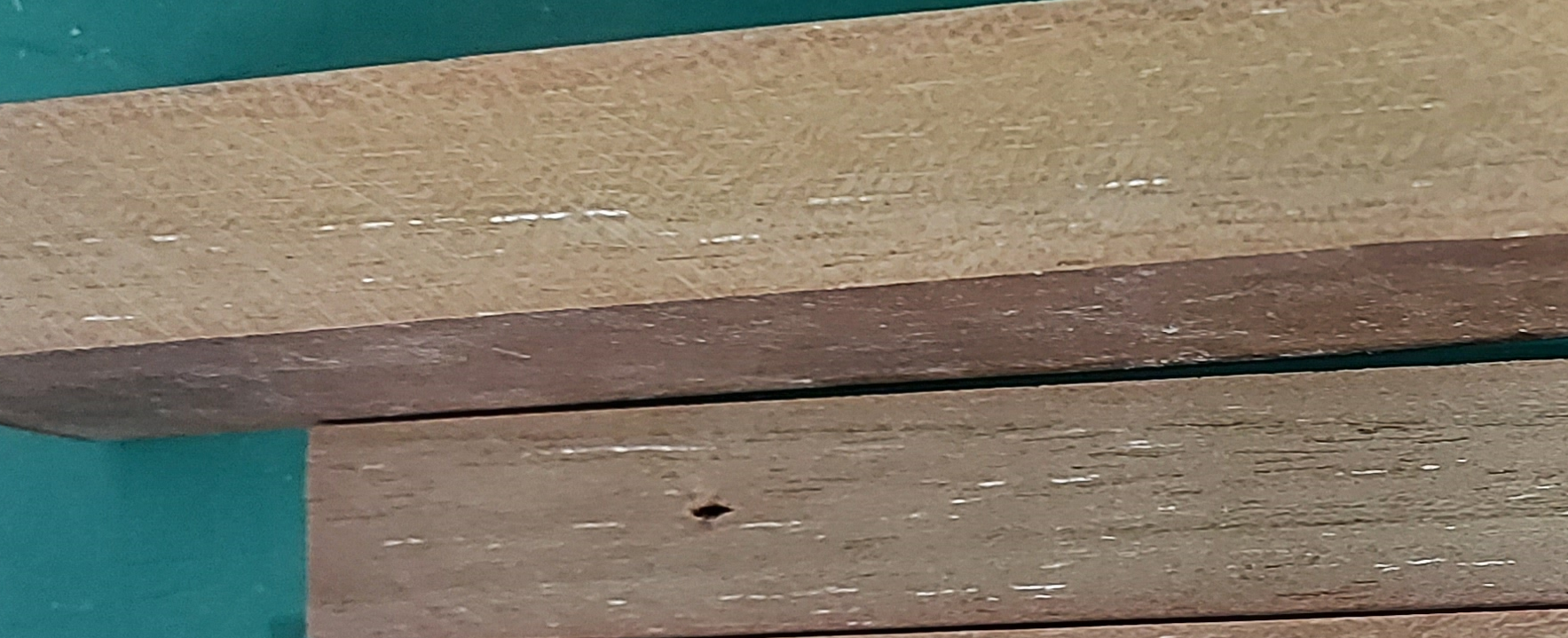
 thank you Bruce but it does not look like any maple I've seen... possibly chinese maple? I've contact my supplier of choice and wait a response.
 -
Seems like it is time to contact the exotic lumber yard
-
from google search: Unbleached Titanium White is a warm beige tinted white. This oil paint can be used to lighten colors with a different effect than regular whites.
-
I am beginning to believe it to be a not so rare species called Adhmad Rúndiamhair.
-
I have been given a very small quantity of wood (one piece 1" x 4" x 12" or 25.4 x 101 x 305mm) and I haven't a clue what it is. Can anyone help me identify it. it is a more dark than light shade of brown, with short streaks of white in it. The surface was stained and the end has something like a glue on it so I cannot see the end grain. I cut a few strips as I thought I'd use it but then I saw the actual colour pattern and now it's got me wondering. There is no specific scent and no appreciable weight to it.

-
AHOY neighbour! (Nice to see you back) Sort of looks like that's what she needs to fall into place doesn't it.
-
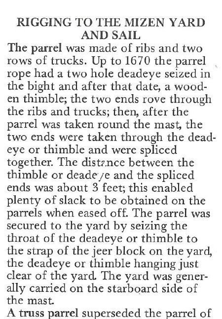
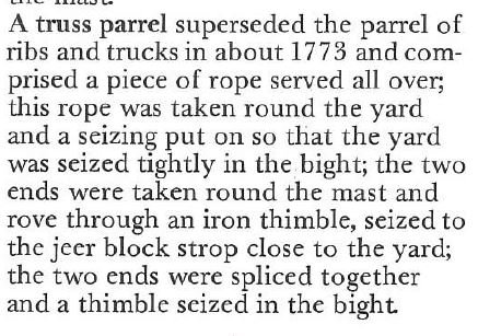
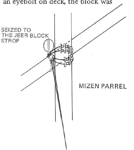
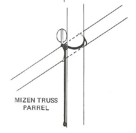
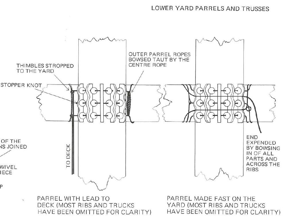
Sorry about that each image was uploaded with the source in it's name... eg: Truss Parrel pg105-5 (-5 means 5th image from the page) The Masting + (and) Rigging of ESOW (English Ships of War 1625-1860 by James Lee) If you copy them out you will have the info I thought for some reason it would display if you hovered your mouse over them
-
there are a couple more but I fear I may be pushing things a bit with my photos from Index - The Masting and Rigging of English Ships of War 1625-1860 by James Lee:
-
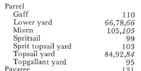
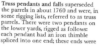
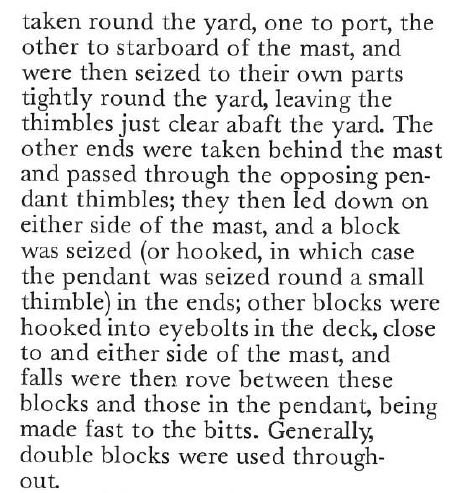
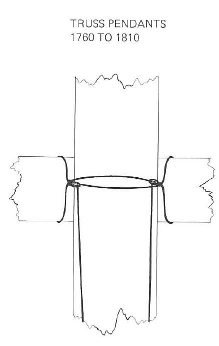
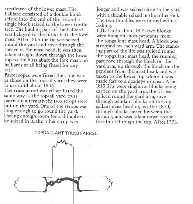
and last bit... from The Masting and Rigging of English Ships of War 1625-1860 by James Lee pg 105
-
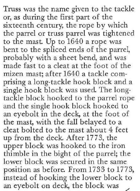
here is some more info from The Masting and Rigging of English Ships of War 1625-1860 by James Lee, pgs 66 and 67
-
does this help? Top Gallant Yard from The Masting and Rigging of English Ships of War 1625-1860 by James Lee, pg 95
-
Copper? I have been considering strips of black paper as there will be 148 of them and no one will be the wiser. I do admire anyone that sticks to it.
-
I know! I know! It's your engineering background. Me too!! Our type seems to always gravitate towards the spectacular as opposed to KISS (Keep It Simply... Silly?) Now that we have to build it ourselves we need to learn a new skill set... seeing the forest for the trees. 😉
-
They seem quite short for the capstan.
-
Thanks for the info Mike It looked like the glue was in the hole first and seemed awkward.
- 968 replies
-
- 2
-

-
- hahn
- oliver cromwell
- (and 1 more)
-
Mike Do you put a dab of glue in the drilled hole and then inset the treenail, or do you chamfer the lead corner of the treenail as a leader to help initial insertion and apply a dab of glue to the end of the treenail then insert it?
- 968 replies
-
- 1
-
-
- hahn
- oliver cromwell
- (and 1 more)
-
Regarding the name I almost passed on looking at your build but then thought I was being stupid... after all, some ships were renamed two or three times. I had no idea what your ship might be. I am glad I took a peek. Alan O'Neill (From the Irish County Cork O'Neills)
- 968 replies
-
- 5
-
-
- hahn
- oliver cromwell
- (and 1 more)
-
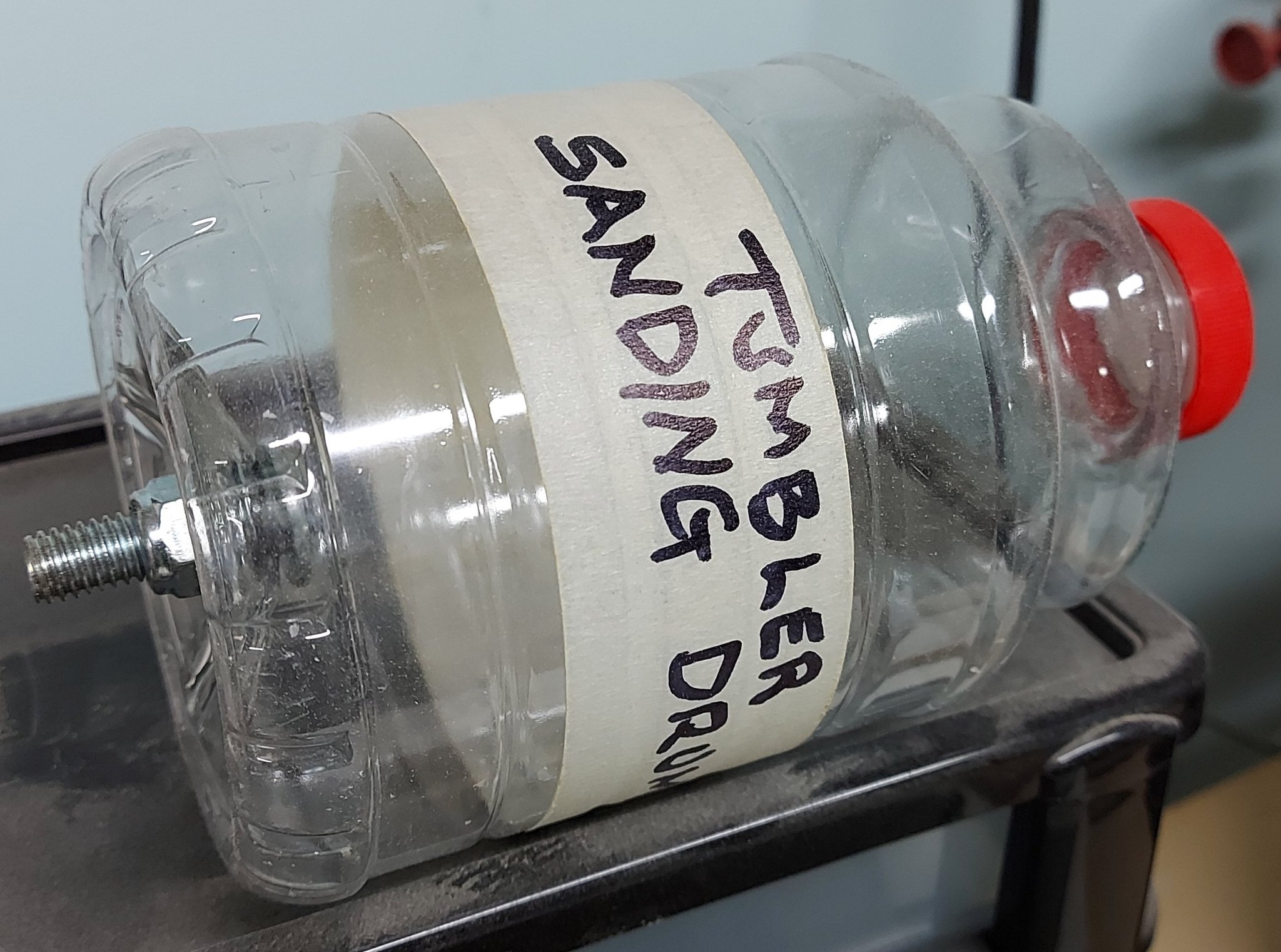
I had the idea weeks ago to make a sand tumbler. I saved a Orville Redenbacher Popcorn plastic bottle and screw top, and drilled a hole in the base for a bolt. I slipped a flat washer and O-ring over the bolt to seal it to the bottle base to keep the sand in. I intend to get a small bucket of clean beach sand to use in the "tumbler", but haven't made it out to the shore of Lake Erie just yet (a 30 minute drive). I'd fill the container about quarter full to start and slip the bolt into my wood lathe set to it's slowest speed. Toss in some scrap bits with holes drilled through for a test run. To empty it I'd dump the contents back into the bucket with a screen/sieve to catch the parts. I got the idea from fluidized bed furnaces and hopper screw augers used to remove debinded casting sand from Solution Furnaces. The former had sand flow like a fluid through every crack and crevice to heat treat gears, bolts, golf clubs, etc.. The latter seemed to be self cleaning via sand rubbing against the hopper and chute. So I imagine the sharp edges of the tiny sand grains would wear away and soften the edges of blocks, grooves and holes. All I need now is the darned sand.


-
FYI The official response from DREMEL regarding their right angle drill attachment and their flex-shaft: "Unfortunately, the right angle and the flex shaft are both attachments for our rotary tools, but are not compatible with each other." Seems like a missed opportunity and short sightedness on the part of their engineering and marketing group... and so I suggested they might want to get their design group working on it. Of course I expect no action, but will be pleasantly surprised if a year and a half from now it is offered.
- 968 replies
-
- 3
-
-
- hahn
- oliver cromwell
- (and 1 more)
-
You, like others I follow, are well ahead of me (which is a good thing for me!). I was in the shop drilling holes with the dremel and flex-shaft when I took a break and read the update on your build from my phone. The dremel was dangling there in front of me. I did a quick search and some came up (but read on). If you can use your homemade mini drill in the space, holding it in your hand (fingers?) I imagined a dremel attachment might not be much more difficult. When I went upstairs later I did a better search on my computer and I am not certain they make one for the flex-shaft or for number size drills. They seem to only connect directly to the Dremel unit. I've contacted Dremel to ask. I have an ancient model that doesn't come up on their drop down menus for filling in their forms. Mine has replaceable brushes that I could not find on the website. YIKES. (I should have asked about that also).
- 968 replies
-
- 3
-
-
- hahn
- oliver cromwell
- (and 1 more)
-
I wonder if a dremel with a 3 foot flexible cable and a 90° drill attachments would be a good alternative. FYI: My first flex cable burnt through the casing as I didn't know it needed to be taken apart and coated with grease occasionally. The next one has lasted me 20 years.
- 968 replies
-
- 4
-
-
- hahn
- oliver cromwell
- (and 1 more)
-
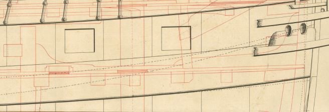
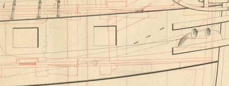
Mark, Whether they were part of the Bellona or not I cannot say but they were in the Bellerophon, Elephant and Goliath contracts and were on the Elephant and Goliath build drawings as you can see below. Although I am years behind you I am learning a lot. Thanks!
-
Look at post 2025 above Near the end
-
I starting draughting in high school, grade 9. I had draughting classes for all four years. Went to college for 3 more years and was exempted from engineering drawing (draughting). On graduating I got a job in 1975 as a junior draughtsman, on a draughting board... and found out how much I didn't know. After years of training I was a senior draughtsman. We had tall sitting stools at our tables but rarely used them. We also did "napkin sketches"... now there is a lost art. One fellow made left and right gremlin foot print stamps (toes and all) from two erasers and when you came in in the morning you'd find graphite foot prints across your drawing sheet. I did pencil and ink drawings back then, but in came computers with AutoCAD. I miss seeing the draughtman's dance: doing a few lines, standing back to review the work, stepping forward to fix or add to it. With these computers everything was 2D and I eagerly climbed on board. No more graphite smudges on my drawings. The other plus was everyone's lettering was crisp clear and identical. It was beautiful until you had to revise someone else's drawing and found they used umpteen separate short lines when one long line would suffice. I could never get use to sitting all day. When the option came to use a standing table I jumped at that. I would have loved to have a treadmill but the boss wouldn't spring for that. So I went for a walk every day at my break instead. Then came 3D and my pet peeve for numerous short lines was exponentially increased as the darned programmes don't believe in a single line anywhere. Don't get me wrong, I love 3D draughting. If you've ever had to clean an area for clarity, it is a nightmare. So retirement came just at the right time for me. Now I use the Standard version of DraftSight (annual subscription) for my love of draughting, and the free hobbyist version of Fusion 360 for my love of 3D modelling (and preparing files for 3D printing). I had a 4 foot draughting table at home but sold that off years ago. I loved SolidWorks but personally found AutoDesk Inventor was a better program... I simply cannot afford the expense in retirement.