


AON
-
Posts
2,866 -
Joined
-
Last visited
Content Type
Profiles
Forums
Gallery
Events
Everything posted by AON
-

Membership expiring? How can I tell?
AON replied to Srodbro's topic in NAUTICAL RESEARCH GUILD - News & Information
You can go to the NRG website from this forum, up at the very top second drop down menu from the right is "NRG Home Page" -
Thank you for the kind words regarding my two side builds: the plank river raft and the Aleut hunting kayak. The raft was published in the last NRJ (Nautical Research Journal) and the kayak will hopefully be published in the fall issue. Well, it has been a long time but... nope, I haven't finished the darned frames. Yesterday I did complete the making and installing of the forward straight frames from the cant frames back to midships (C) FWD, approaching the dead flat. As those either side of the dead flat are a similar but thicker frame I will do them last to fill in the gap. Tomorrow I begin installing the aft half and hope to have them done by... sometime. So y'all can go back to sleep now.
-
Shipman and Weflack. I agree with the free use as described. I also like Lee's but sometimes find it difficult to digest. Barkeater. Petersson is a fine book for illustrations that I seem to gravitate to myself and it makes things easier to follow. The issue is does ObviousNewbie care to rig his model in such a way.... or does he want to simply secure the yard to the mast... or both? If it is both, then I believe a pin, be it metal or wood, will do the job of securing it in place, then follow with proper rigging. If ObviousNewbie is interested in seeing illustrations by Petersson please contact me via PM. Alan
-
Bonjour Francis, Vous habitez dans une des plus belles régions de France et votre modèle est assez sympa (même si la photo doit être tournée). Bien joué. Bienvenue sur le forum (google translate is a wonderful thing)
-
Joachim and Bob, I've seen a number of different sketches depicting how the breeching rope was secured at the cascabel. The earlier cannons did not have the "ring" or "thimble" above the "button" or "ball". The later versions did, an improvement as the breeching rope required a more positive means of being secured. One method I've seen prior to the ring was to wrap the breeching rope around one turn starting from below. Where they cross was whipped (bound together with a smaller sacrificial line that could be cut free if required) to keep the wrap tight and not slip off. Another version was to pass the breeching rope over top and short splice a similar sized rope on either side so it passed below and trap it in the reduced neck portion of the cascable. Once the design was improved with the addition of the ring or thimble the breeching rope simply passed through it.
-
I've thought about it. Even researched Youtube videos to see how to cover it in fibreglass. Then I pictured myself rolling over and the words "I've fall'n and I can't get up" came to mind. But you go for it!
-
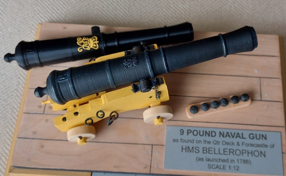
I have finally corrected a major error with this build. I kept telling people at the time I could not see the royal cypher, so I enlarged it and then painted it yellow ochre. I had printed a new one piece barrel to replace my two piece. At one of our local club meetings one member had mentioned I should paint this new barrel with several light coats of Beauty Tone Flat Black Enamel Acrylic paint.. I did this back in February 2019 and it looked great, except I still couldn't see the cypher. He suggested highlighting it and any other proud items with a light brushing of a hint of a lighter shade of black (smokey grey). I have procrastinated.... because I couldn't see it. Well I have had cataract surgery in both eyes this August and September and now... I CAN SEE IT! Today I touched up the royal cypher and other proud items, removed the old barrel (tossed it in the trash), and mounted the new barrel. Here are the results. You can see the difference.
- 125 replies
-
- 12
-

-
- 9 pound naval cannon
- 3d cannon barrel
- (and 1 more)
-
Good afternoon Druxey! An article by Eric Schrade in the 2010 May/June issue of Ships in Scale, augmented with articles by David Zimmerly in the February/March and April/May 1983 issues of the Small Boat Journal. I am presently 3D printing my mounting device for the Kayak.
-
Well, I just today finished my one hole 16'-9" Aleutian hunting Baidarkas (Kayak) frame build. Photo posted below for your amusement. I will be writing this one up and submitting it for publication in the Nautical Research Journal. My River Raft (above) was published in the issue that came out today. Then I'll be back full time on my Billy Ruffian.

-
Are there any decent clamps?
AON replied to bigcreekdad's topic in Modeling tools and Workshop Equipment
Not to be funny... I find all clamps are very good until you need that special one... like right now. -
Good evening Simon and welcome aboard! Alan O'Neill
-
You've put a lot more effort into your drawings then I have! Should be fewer surprises. BZ
-
Dead flat stations
AON replied to Don Case's topic in Building, Framing, Planking and plating a ships hull and deck
I cannot say for your build. -
Dead flat stations
AON replied to Don Case's topic in Building, Framing, Planking and plating a ships hull and deck
on both! -
Dead flat stations
AON replied to Don Case's topic in Building, Framing, Planking and plating a ships hull and deck
Possibly an online search of the National Maritime Museum (NMM - RMG) in Greenwich might reveal a sloop framing drawing. https://collections.rmg.co.uk/collections.html#!cbrowse -
Dead flat stations
AON replied to Don Case's topic in Building, Framing, Planking and plating a ships hull and deck
Don I find what Jagger describes as very interesting. He describes R+S (Room and space) to include 1/2" air gap between frames for a 70 guns ship. For my build (74 gun launched in 1786) there were 3 drawings available. 1) Body, Half Breadth and Sheer Plans, 2) Disposition of Frames, and 3) Deck Plans. The space between frames per the contract (at the keel) at dead flat was 1/4". It increased as you moved towards the stem and stern post and the frames became narrower. My #1 Plan showed 9 frames each side of dead flat up to about the 2nd water line. Nothing was shown above that. Thank goodness I had plan #2 available. Your half breadth plan shows all the station lines, one half is from the stern to dead flat and the other from the stem to dead flat. Your build is on top of the full plan. Does the other view reveal anything regarding frames at and about the dead flat station? I do not know anything about a sloop construction so cannot offer anything to help you. Possibly a search for other sloops on the forum might reveal more. -
Dead flat stations
AON replied to Don Case's topic in Building, Framing, Planking and plating a ships hull and deck
Sorry for not answering your question. 1. it is good to know the ship you are asking about. I believe she was a 10 gun sloop. 2. the year helps in that multiple ships carried the same name over the years, but were different construction. 3. looking at the plans helps. some have the plans but cannot read them. Dead flat is a location and a station/frame identification. I believe the bracketed frame stations are similar shape to the dead flat but are not identified as the dead flat station. Other frames beyond the dead flat and bracketed ID are square frames but contoured towards the bow/stern until you get to the cant frames. Cant frames are not square (90 degrees) to the keel. You have one dead flat and multiple similar contoured frames. -
Dead flat stations
AON replied to Don Case's topic in Building, Framing, Planking and plating a ships hull and deck
can you post an image of your body plan? What is the ship? Year? -
For me it was the support. I was installing the forward cant frames, alternating starboard/port so the darned thing shift one way then the other. Thankfully I noticed before I got too far and took them off, nailed (actually wood screws) the support solid, then re-installed the frames.
-
Thank you for another excellent video. Regarding interpreting 2D drawings. Having worked in the industry for many years I found the introduction of 3D models and views to be invaluable in getting my message across to shop people who had trouble reading more complicated 2D prints. Having said that, I too have the TFFM volume you are using, and have the 3D images package. I find they are an excellent reference to use with the books, and have cleared up some confusion for this old 2D draughtsman! Regarding the 3" shift of your frames. It was before you made the stem and stern supports stationary! I had the same problem, except I cannot blame termites.... it was damn shop gremlins (?).
-
Did you have to take it outside so I would have to listen to the tropical birds then imagine the gentle warm breeze coming in off the beach just before I have to go outside to shovel snow! 🤔
-
Presently I am using a discarded kitchen rice steamer (the wife wanted a new one so I snagged the old one).
-
Just did a google search and Iroko does seem to have tiny white streaks in it.... and I did develop a couple small rashes after working with it. At first I thought it might be Teak by which it is aka African Teak although it is not teak. The attached google photo is somewhat darker than my piece but I am going to assume this is what it is until something more convincing comes along. Thanks again!

-
Thank you all. I will look up Iroko as I've never heard of it before. The small piece of this mystery wood (Adhmad Rúndiamhair) that I was given seems to have been reclaimed from a piece of furniture (my guess). I have heard back from the two wood suppliers I deal with ( Exotic Woods in Burlington, Ontario and McQueen Custom Cuts which is nearer to me and supplies to local business and wood carvers), and neither have a clue as to what this might be. I certainly hope it is not a fungus. It doesn't seem to be. As for protection from wood dust, I always wear my dust mask (with HEPA Filters) and eye protection. I am constantly concerned for my eyes now ( Cataracts for which I recently had surgery, and Branch Retinal Vein Occlusion caused by Macular Edema for which I've been getting injections in my left eye for the last 4 years), and my Father-in-law worked at a lumber yard for 30 years which gifted him with COPD in his retirement years.

