
Supplies of the Ship Modeler's Handbook are running out. Get your copy NOW before they are gone! Click on photo to order.
×


James H
-
Posts
6,009 -
Joined
-
Last visited
Reputation Activity
-

 James H got a reaction from popeye the sailor in 1:8 1965 Shelby Cobra 427 S/C - Agora Models
STAGE 42: DASHBOARD DIALS AND SWITCH
More dashboard goodness now as the dial stickers are affixed to the holding plate.
The clear lenses board is now pushed into position on the rear of the chrome surround.
Then the dial faces holder is sat on top of this, behind the lenses board.
Remember the free-floating switch? This is what it operates. A microswitch is pushed into position in the dial holding plate, and this fitted to the dials assembly I just made, before being fitted to the rear of the instrument panel using three screws.
-
James H got a reaction from popeye the sailor in 1:8 1965 Shelby Cobra 427 S/C - Agora Models
Pack 6
Hot on the heels of the last pack come this next one which looks at building up some of the driver's office.
STAGE 41: DASHBORD SWITCHES AND STEERING ROD GUIDE
Definitely one for those detail freaks 😁
First, dashboard plates 1 & 2 are pushed into place. I actually used a little CA on #2 as it was a little sloppy.
Plate #3 is then pushed into place and secured by a screw from behind. Just look at the detail on that 🤗
Now, the steering rod guide is screwed into position from the rear,
A number of injection moulded switches and knobs are added, some of them printed with details. These look excellent. one of these is quite clearly for a switch as it's left free-floating.
-
James H got a reaction from popeye the sailor in 1:8 1965 Shelby Cobra 427 S/C - Agora Models
STAGE 48: MOUNTING BOX AND MAIN SWITCH
Another switch! This time a toggle for the car's on/off circuit. This pushes into place as seen here and a clip/screw used to secure it. The switch took a little effort to seat evenly.
The mounting box is now fitted with pipes and the united screwed into position on the underside of the car. A little lid is also supplied. No surprise that this is where the batteries for the electronics will eventually fit.
Last up is another cable management clip that helps to hold down the cable that I originally taped down for safety.
That's it for another month!
-
 James H got a reaction from mtaylor in 1:8 1965 Shelby Cobra 427 S/C - Agora Models
STAGE 48: MOUNTING BOX AND MAIN SWITCH
Another switch! This time a toggle for the car's on/off circuit. This pushes into place as seen here and a clip/screw used to secure it. The switch took a little effort to seat evenly.
The mounting box is now fitted with pipes and the united screwed into position on the underside of the car. A little lid is also supplied. No surprise that this is where the batteries for the electronics will eventually fit.
Last up is another cable management clip that helps to hold down the cable that I originally taped down for safety.
That's it for another month!
-
James H got a reaction from popeye the sailor in 1:8 1965 Shelby Cobra 427 S/C - Agora Models
STAGE 47: ACCELERATOR PEDAL & SWITCH, BRAKE PEDAL & SWITCH, CLUTCH PEDAL, FLOOR PLATE
The pedal floor plate just pushes into position on top of the driver's floor mat, and then the accelerator, brake and clutch pedals are fitted as seen with screws from the reverse.
Microswitch assemblies are now fitted for two of the pedals. A switch is just pushed into a holder and the holder screwed to the cockpit reverse. A quick test of the switches with the pedals shows a positive action. No problems there!
Cable management clips are now used to route the cables along the underside.
-
James H got a reaction from popeye the sailor in 1:8 1965 Shelby Cobra 427 S/C - Agora Models
STAGE 46: GEAR LEVER, HANDBRAKE AND U-BAR
This simple pack adds the hand brake and gear levers, plus the console u-bar. The hand brake just pushes into the side of the interior while the remainder screw into place from underneath.
-
James H got a reaction from popeye the sailor in 1:8 1965 Shelby Cobra 427 S/C - Agora Models
STAGE 45: COCKPIT REAR WALL
Same for the cockpit rear wall that is now carefully offered up to the cockpit interior and secured with four more screws.
-
James H got a reaction from popeye the sailor in 1:8 1965 Shelby Cobra 427 S/C - Agora Models
STAGE 44: RIGHT FLOOR SECTION AND FLOOR MATS
More delicate interior work now that I try so hard not to touch with my fingers! The passenger and driver floor mat just push neatly into position.
-
James H got a reaction from popeye the sailor in 1:8 1965 Shelby Cobra 427 S/C - Agora Models
STAGE 43: CENTER CONSOLE AND LEFT FLOOR SECTION
Some internal work I always find these a little hard to photograph as they are so black and have a velvet texture to them which can be easily marked with just touching. I find a piece of de-tacked tape is useful for removing any skin flakes or stray fibres/hairs from the surface. The two main sections are screwed together as shown and a cable clip fitted into position on the underside.
-
James H got a reaction from mtaylor in 1:8 1965 Shelby Cobra 427 S/C - Agora Models
STAGE 42: DASHBOARD DIALS AND SWITCH
More dashboard goodness now as the dial stickers are affixed to the holding plate.
The clear lenses board is now pushed into position on the rear of the chrome surround.
Then the dial faces holder is sat on top of this, behind the lenses board.
Remember the free-floating switch? This is what it operates. A microswitch is pushed into position in the dial holding plate, and this fitted to the dials assembly I just made, before being fitted to the rear of the instrument panel using three screws.
-
 James H got a reaction from MadDogMcQ in VAPORETTO MOTOBATTELLO VENEZIANO by MadDogMcQ - Panart Art.730 - 1:28
What a nice job. Looks super smooth too.
You can sort of get away with a few plank marks on a wooden hull, but not a Vaporetto. 👍
Can't get Plastikote? Never heard of Amazon Prime? 😆
If I'd thought about it, I had a spare here you could've had.
-
James H got a reaction from mtaylor in 1:8 1965 Shelby Cobra 427 S/C - Agora Models
Pack 6
Hot on the heels of the last pack come this next one which looks at building up some of the driver's office.
STAGE 41: DASHBORD SWITCHES AND STEERING ROD GUIDE
Definitely one for those detail freaks 😁
First, dashboard plates 1 & 2 are pushed into place. I actually used a little CA on #2 as it was a little sloppy.
Plate #3 is then pushed into place and secured by a screw from behind. Just look at the detail on that 🤗
Now, the steering rod guide is screwed into position from the rear,
A number of injection moulded switches and knobs are added, some of them printed with details. These look excellent. one of these is quite clearly for a switch as it's left free-floating.
-
 James H reacted to chris watton in Chris Watton and Vanguard Models news and updates
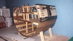
OK, I have now finished with the 'pre-prototype' model, and have all the info I need. A lot of small changes have been made, so this model shows (many) mistakes that the prototype model will not have. What is shown is around 95% of the hull laser cut parts and the castings.
For the boat beams, the U shaped brackets presented a problem. I was going to do them in PE, but wasn't happy with them, as they protrude above the gangway by around 1.5mm. So, these are now perfectly scaled 3-d printed parts, using a very tough resin, and are the kit versions. A very small detail, but happy with the result. The gangway has changed since these pics, with the widest part nearest the quarterdeck moved back a few mm, so the ladders are in between the cannon.
The slots in the quarterdeck were moved back a lot further, in order to show the chequered deck pattern in the aft cabin. Ladders are cut in 0.6mm pear, and look much better, scale-wise. The catheads are made from 5 laser cut and engraved parts each, otherwise they would have looked pretty basic..
Al PE is done and sent off to Italy to be produced for the prototype model, and I now have the task of part numbering everything and doing a full parts list, followed by starting on the CAD drawings for plans...
-
 James H got a reaction from FrankWouts in Jotika Caldercraft new kit the Surprise
That development has been sat on that site since Methuselah stalked the earth.
It's a real shame that any new developments/completed projects stalled.
I do remember Chris Watton once telling me that he was once considering HMS Surprise himself.
-
James H reacted to PRS in Bluenose II by PRS - FINISHED - Artesanía Latina - 1/75th - my first ship model
This will be my first ship construction and decided to make a build log to show my progress and also get ideas and help along the way.
I picked up the Latina Bluenose II as it was local and looks like a decent kit.
First impressions:
Kit packaged well and the fittings in plastic boxes is a nice touch. Wood looks good although the plywood hull has some warpage. No instruction book as they are on a CD. Who uses CD's these days. Had to get my old laptop out to print out the instructions. No scale plan that I could find so placement of parts might be a little hard to determine. Rigging instructions lacking but I think I can deal with it.
At this point I have the hull framed and the deck on and planked.
I did find all the bulkheads needed some slight sanding to fit as the laser cut was too tight. Also the plywood frame was warped which plywood does. I didn't replace it but tried my best to keep it straight.
Here are some photos of my progress so far. Couple minor mistakes but I can live with it and you don't see that I staggered the center when it should have been the same on both sides.
-
James H got a reaction from popeye the sailor in 1:8 1965 Shelby Cobra 427 S/C - Agora Models
STAGE 40: FRONT FENDER LINERS & AIRFLOW INTAKE PANEL
Two screws hold each fender liner to the silver floor base sections, and another screw holds each to the metal chassis making everything very rigid. The car is then flipped over and the airflow intake panel in place before flipping over the correct way and adding two final screws.
As I have Pack 6, I'll post this real soon, and it looks another wonderful project!
-
James H got a reaction from popeye the sailor in 1:8 1965 Shelby Cobra 427 S/C - Agora Models
STAGE 33: REAR FLOOR PANEL
The rear floor panel drops into place as shown and is secured by six screws. Two of these secure the floating driveshaft bracket securely in place giving that area some needed rigidity.
-
 James H got a reaction from Blackreed in 1:8 1965 Shelby Cobra 427 S/C - Agora Models
STAGE 40: FRONT FENDER LINERS & AIRFLOW INTAKE PANEL
Two screws hold each fender liner to the silver floor base sections, and another screw holds each to the metal chassis making everything very rigid. The car is then flipped over and the airflow intake panel in place before flipping over the correct way and adding two final screws.
As I have Pack 6, I'll post this real soon, and it looks another wonderful project!
-
James H got a reaction from popeye the sailor in 1:8 1965 Shelby Cobra 427 S/C - Agora Models
STAGE 38 and 39: FRONT LEFT/RIGHT CONTROL ARMS
It's now the turn of the front suspension to be completed so the front wheels can be fitted. Again, pins are used throughout to hold everything together while allowing the various joints to move about.
The wheel can now be slipped onto the connecting rod, and then a serrated pin used to lock the rod to the control arm. This was done for both left and right wheels.
-
James H got a reaction from popeye the sailor in 1:8 1965 Shelby Cobra 427 S/C - Agora Models
STAGE 34, 35, 37 and 37 (WHEELS!)
These built up exactly as the front wheels, just four screws per rim. You definitely need to soak those tyres in just-boiled water for 5 mins to make it pliable enough to pull around the rim. The fit is superb! Both rear wheels are built over these stages.
A single screw is now used to fit the wheels to the rear of the car. These were done one after the other so I wasn't putting any stresses on anything for too long. When attaching the wheels, the fins on the brake unit need to fit into the slots in the rear rim.
-
James H got a reaction from Blackreed in 1:8 1965 Shelby Cobra 427 S/C - Agora Models
STAGE 33: REAR FLOOR PANEL
The rear floor panel drops into place as shown and is secured by six screws. Two of these secure the floating driveshaft bracket securely in place giving that area some needed rigidity.
-
James H got a reaction from popeye the sailor in 1:8 1965 Shelby Cobra 427 S/C - Agora Models
PACK 5
I have to say Pack 5 went together very quickly and was a very satisfying project.
For me, this one is miles ahead of the beautiful GT500 I'm also building due to all the metal parts and general construction.
STAGE 32: REAR RIGHT LOWER CONTROL ARM
In this stage, we can continue with the suspension stuff that was built in the last pack, and tie some of those literal loose ends up. All of the parts in this are held together with serrated end pins that are pushed home with pointed pliers. The wheel hub built in the last pack can also now be attached.
-
 James H got a reaction from Edwardkenway in 1:8 1965 Shelby Cobra 427 S/C - Agora Models
STAGE 40: FRONT FENDER LINERS & AIRFLOW INTAKE PANEL
Two screws hold each fender liner to the silver floor base sections, and another screw holds each to the metal chassis making everything very rigid. The car is then flipped over and the airflow intake panel in place before flipping over the correct way and adding two final screws.
As I have Pack 6, I'll post this real soon, and it looks another wonderful project!
-
 James H got a reaction from Canute in VAPORETTO MOTOBATTELLO VENEZIANO by MadDogMcQ - Panart Art.730 - 1:28
What a nice job. Looks super smooth too.
You can sort of get away with a few plank marks on a wooden hull, but not a Vaporetto. 👍
Can't get Plastikote? Never heard of Amazon Prime? 😆
If I'd thought about it, I had a spare here you could've had.
-
 James H got a reaction from marktiedens in 1:8 1965 Shelby Cobra 427 S/C - Agora Models
STAGE 40: FRONT FENDER LINERS & AIRFLOW INTAKE PANEL
Two screws hold each fender liner to the silver floor base sections, and another screw holds each to the metal chassis making everything very rigid. The car is then flipped over and the airflow intake panel in place before flipping over the correct way and adding two final screws.
As I have Pack 6, I'll post this real soon, and it looks another wonderful project!