thibaultron
-
Posts
2,640 -
Joined
-
Last visited
Content Type
Profiles
Forums
Gallery
Events
Everything posted by thibaultron
-
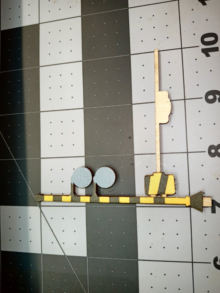
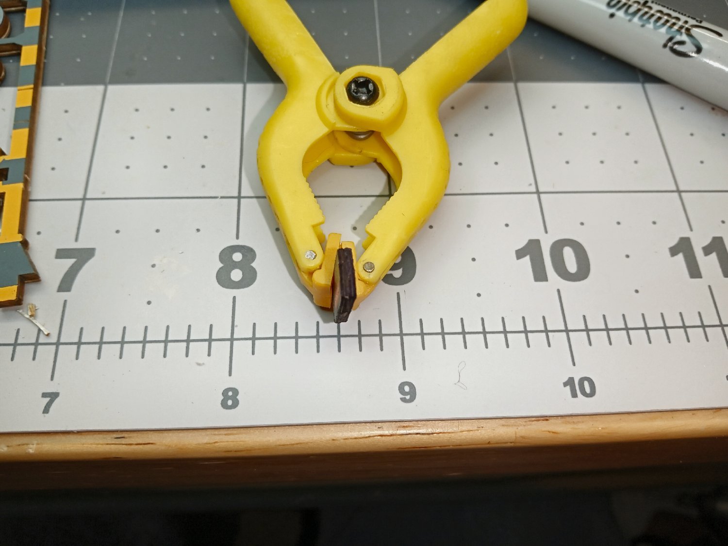
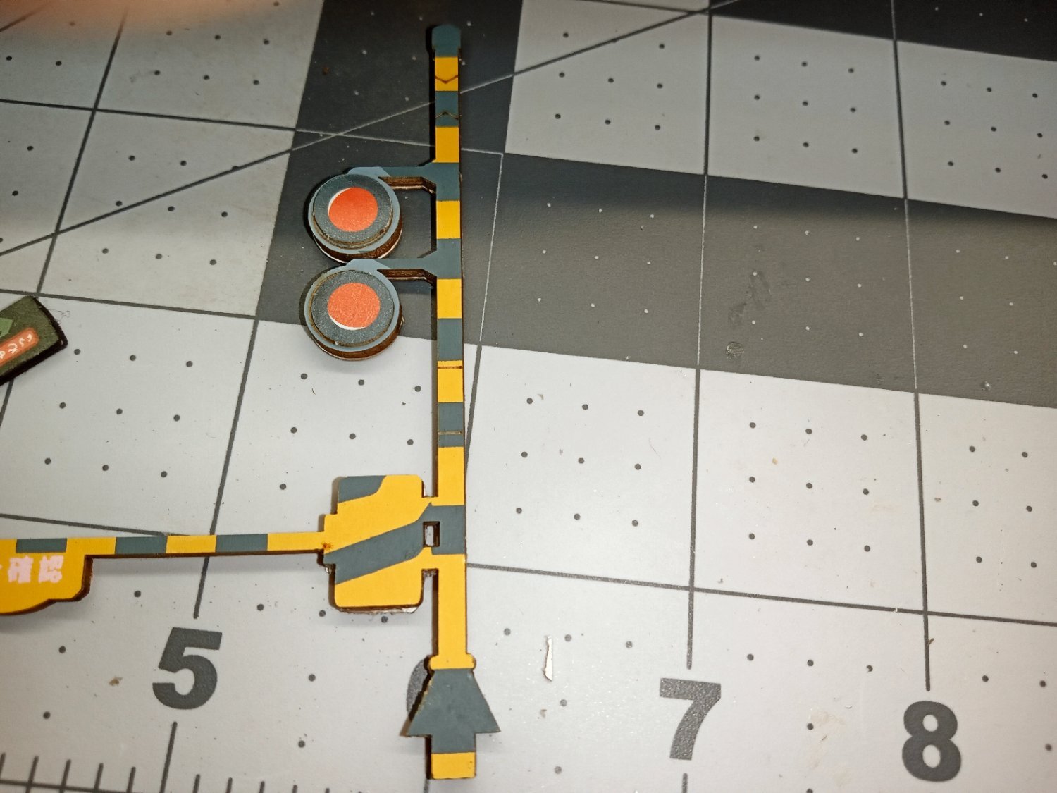
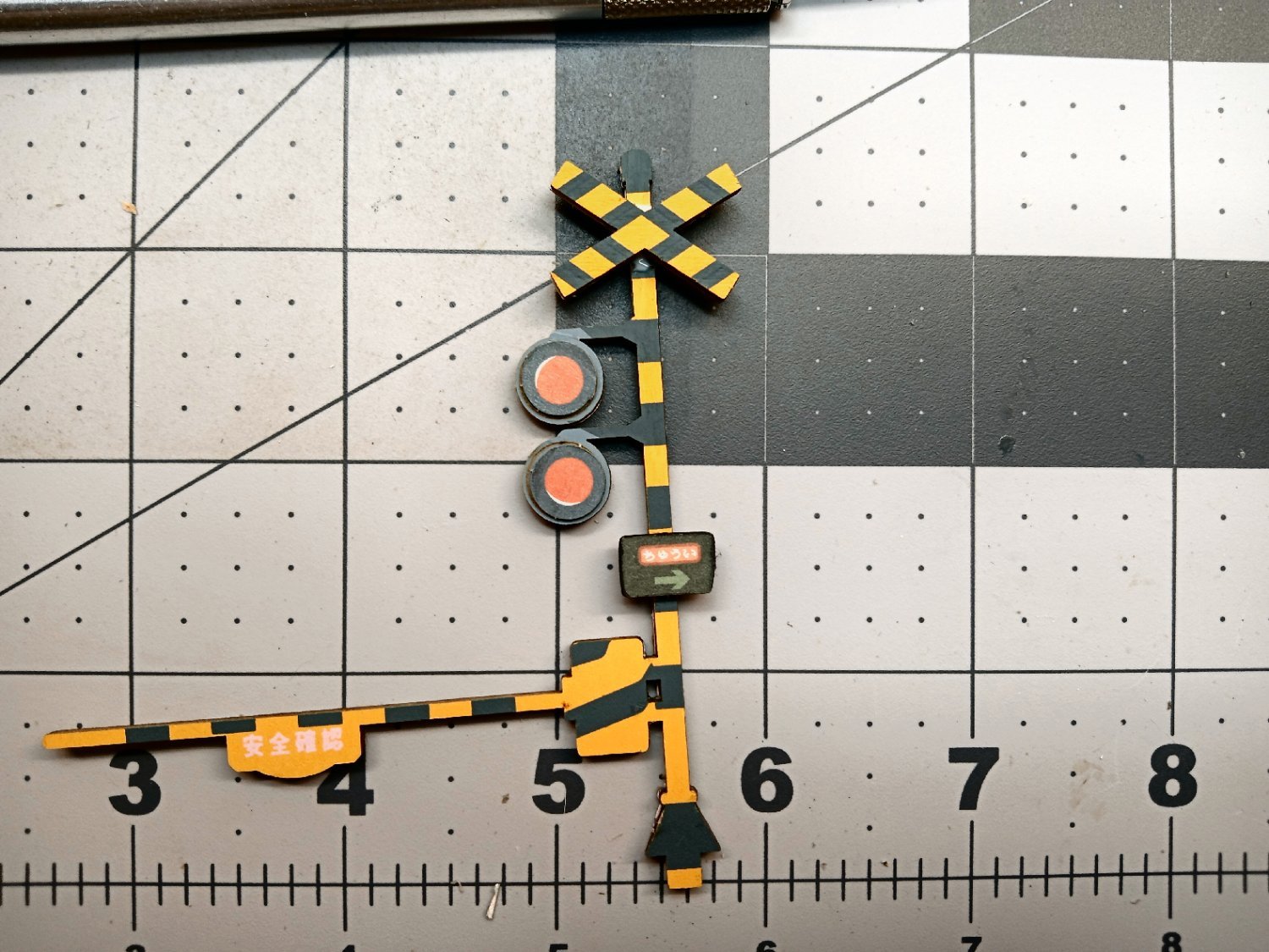
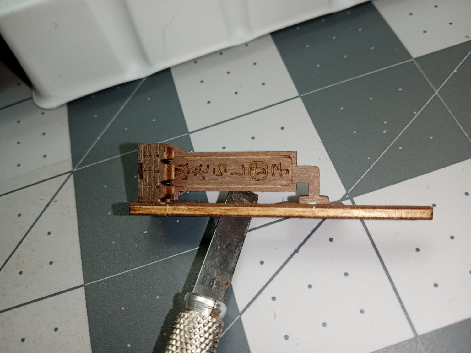
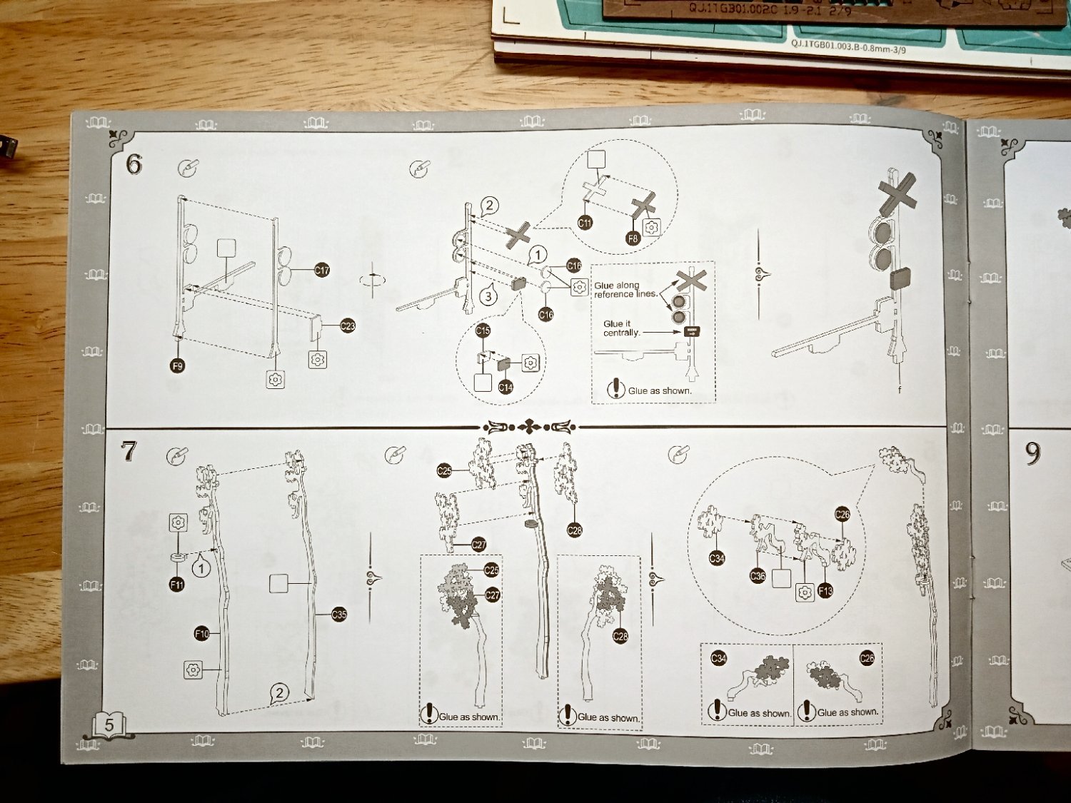
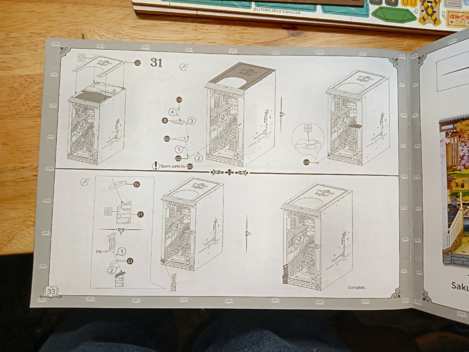
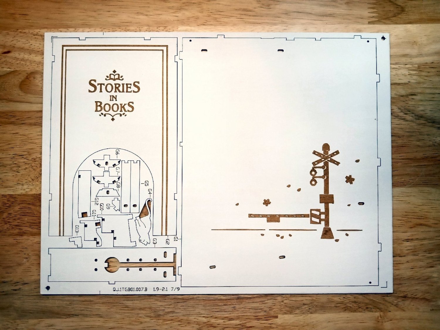
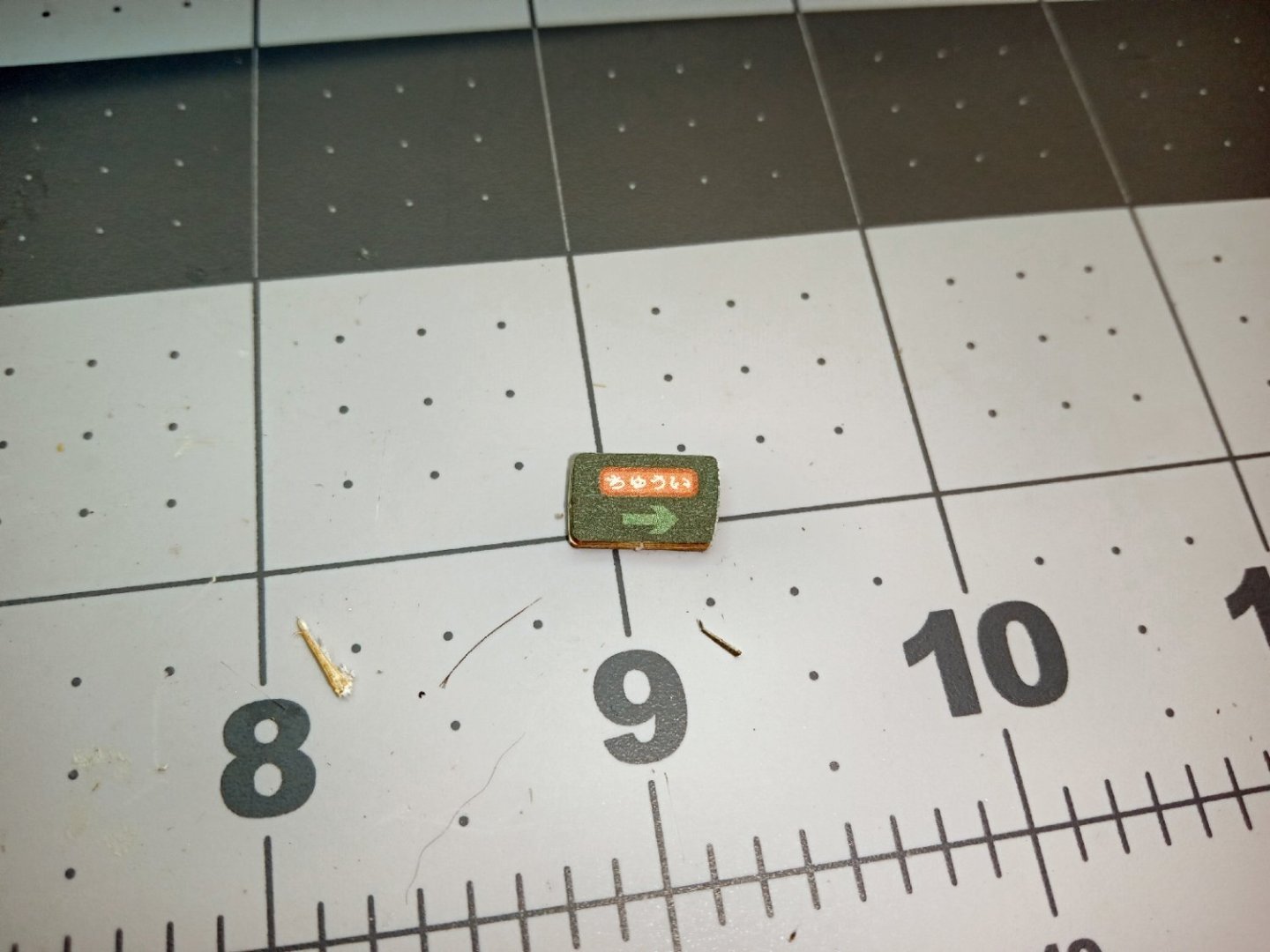
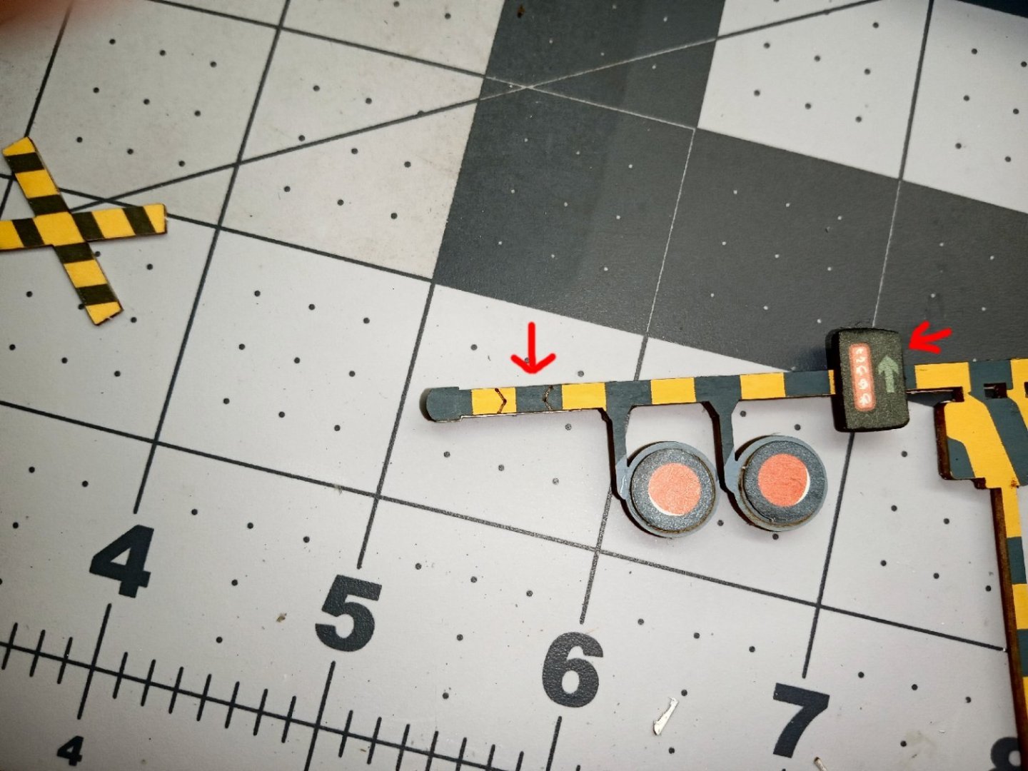
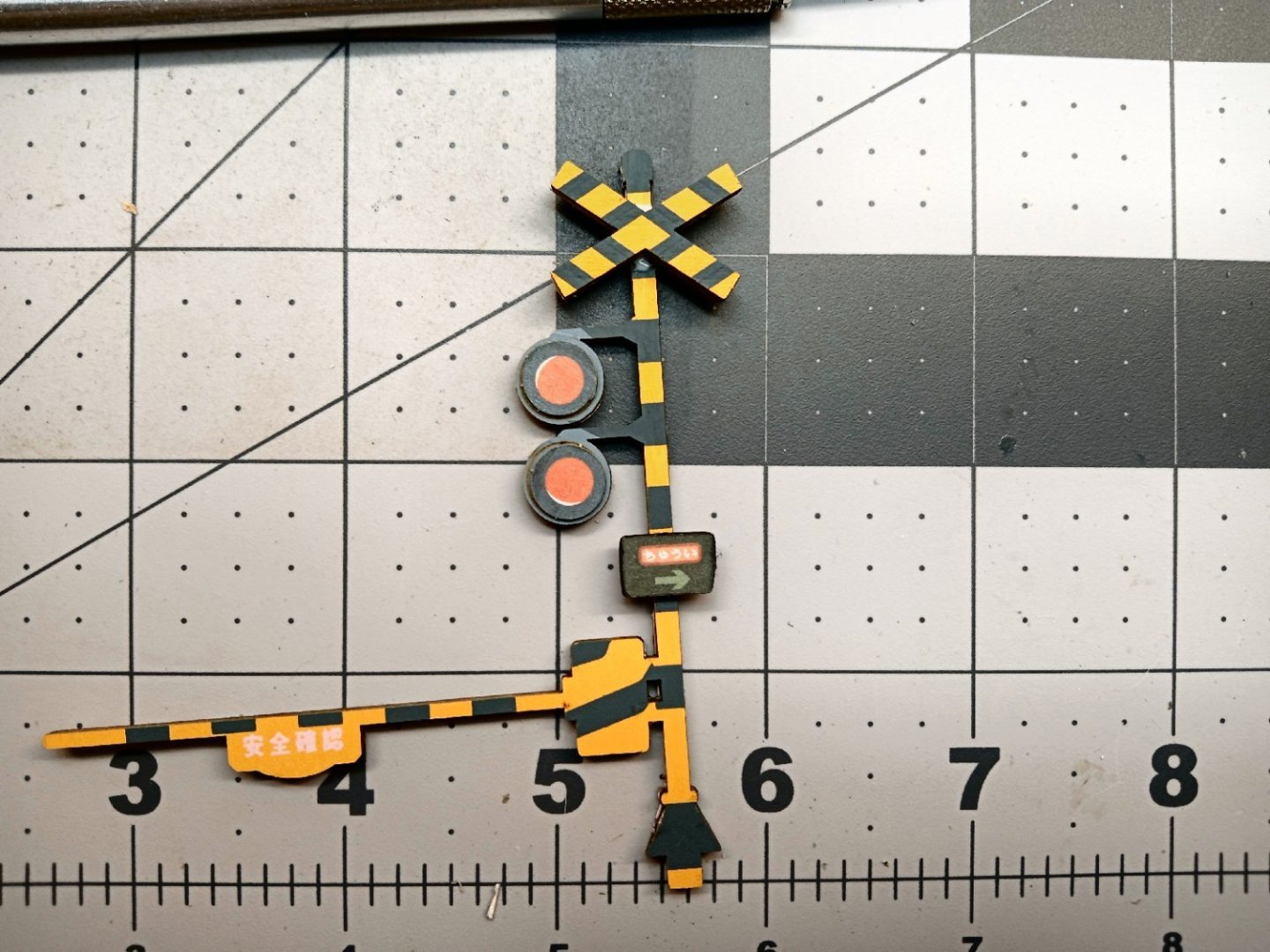
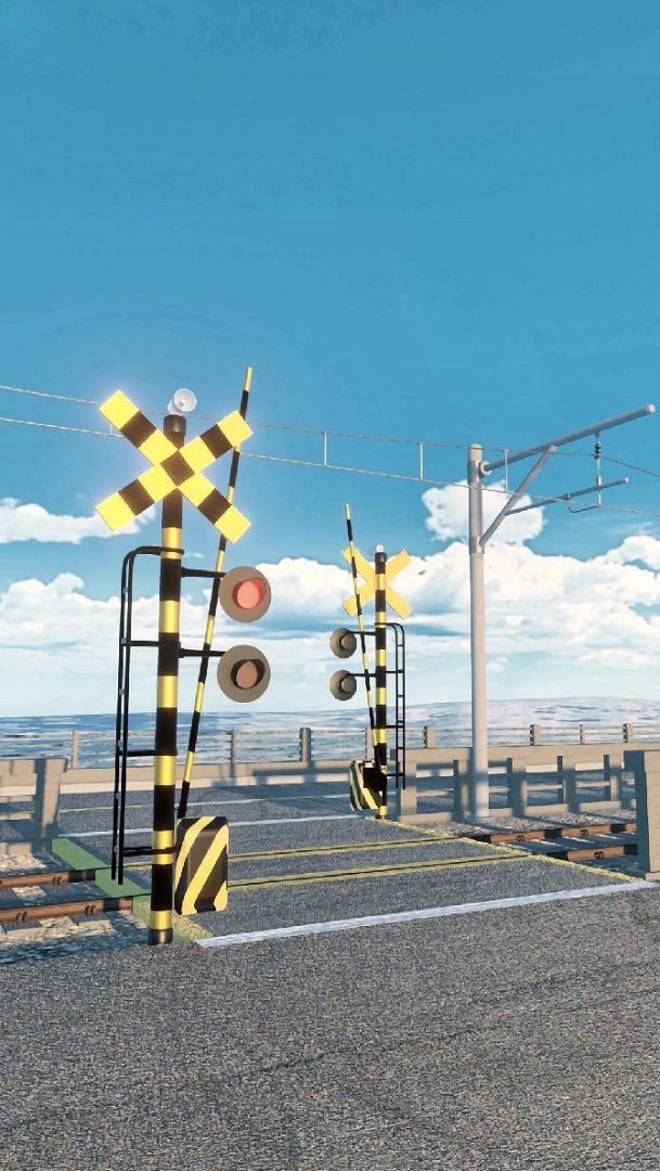
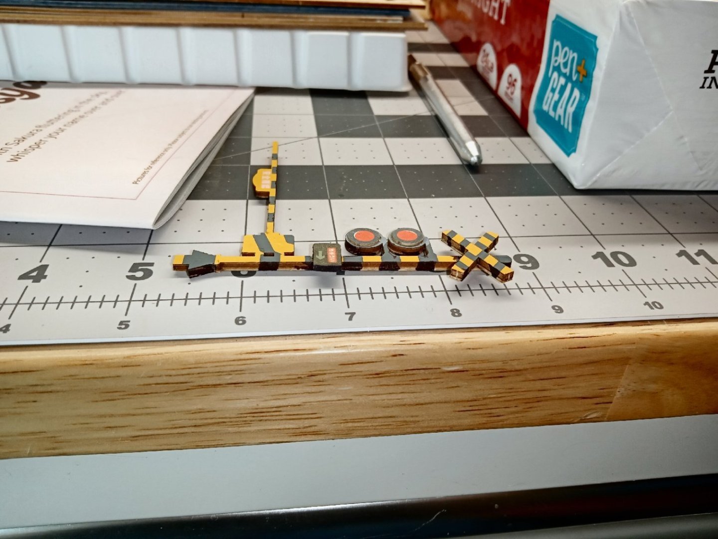
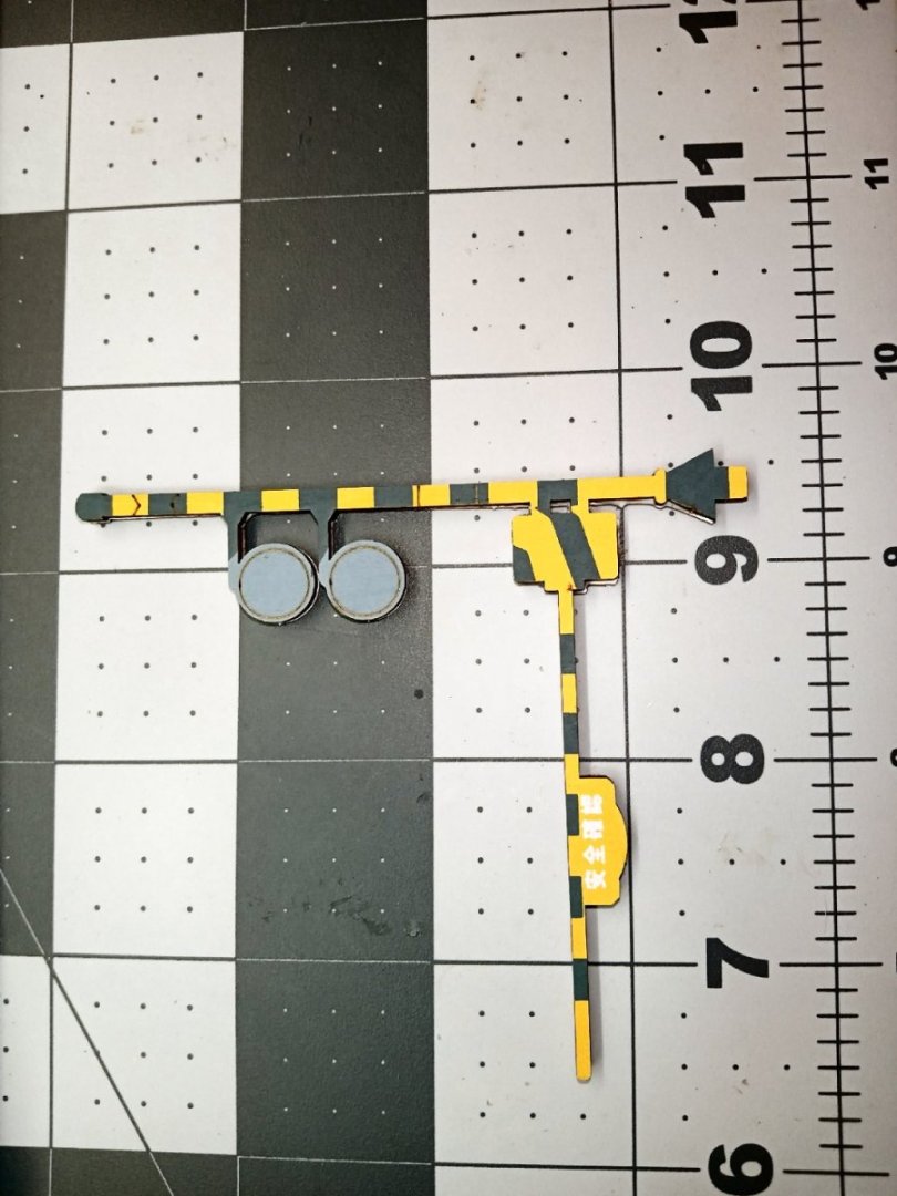
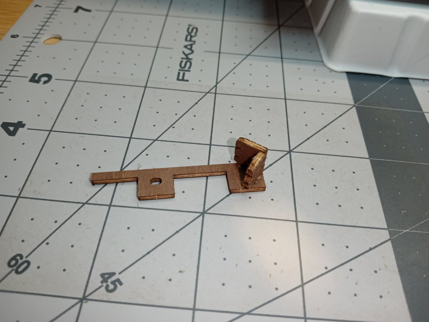
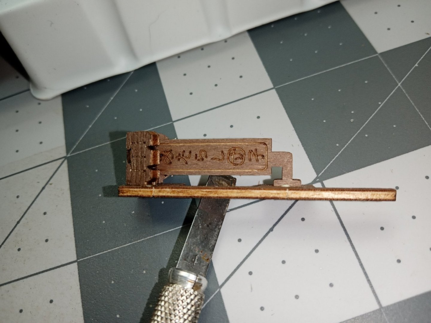
 Part_003 The diorama has a railroad crossing gate, and this is the next assembly to be built. Like the tree, the main body of the crossing gate is a two-layer part. A wooden front and a printed cardstock back. I glued the two together, and the assembly is shown in the two photos below. The upper photo is the front, the other the back. The lower photo also has the rectangular stripped box glued on. The next part needed, is also a two-part assembly. It is a sign with a directional, I assume traffic, arrow. With a mostly black double-sided sign, the raw light-colored edges stood out glaringly. I used a black Sharpie to color the edges. Next the two warning lights are attached. The part has circular outlines to aid in locating them. Next the two-part crossing arms were glued together, then glued to the pole. There are locating marks for both the crossing arms, as well as for the sign (see arrows). Here is a photo of the completed crossing gate. I did get the two-layer pieces a little off register, so I used a blade to trim then to match, on the edges. Looking at the picture of an actual Japanese gate, I see that, like in the US, they have shades over the lights. I may fabricate them before I install it. I used the Sharpie again, to extend the black stripes to the raw sides. With the large tip, it is not the cleanest, but from the distance, will look better than no stripes.
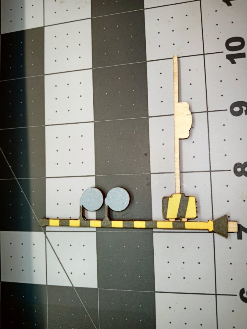


- 25 replies
-
- 10
-

-
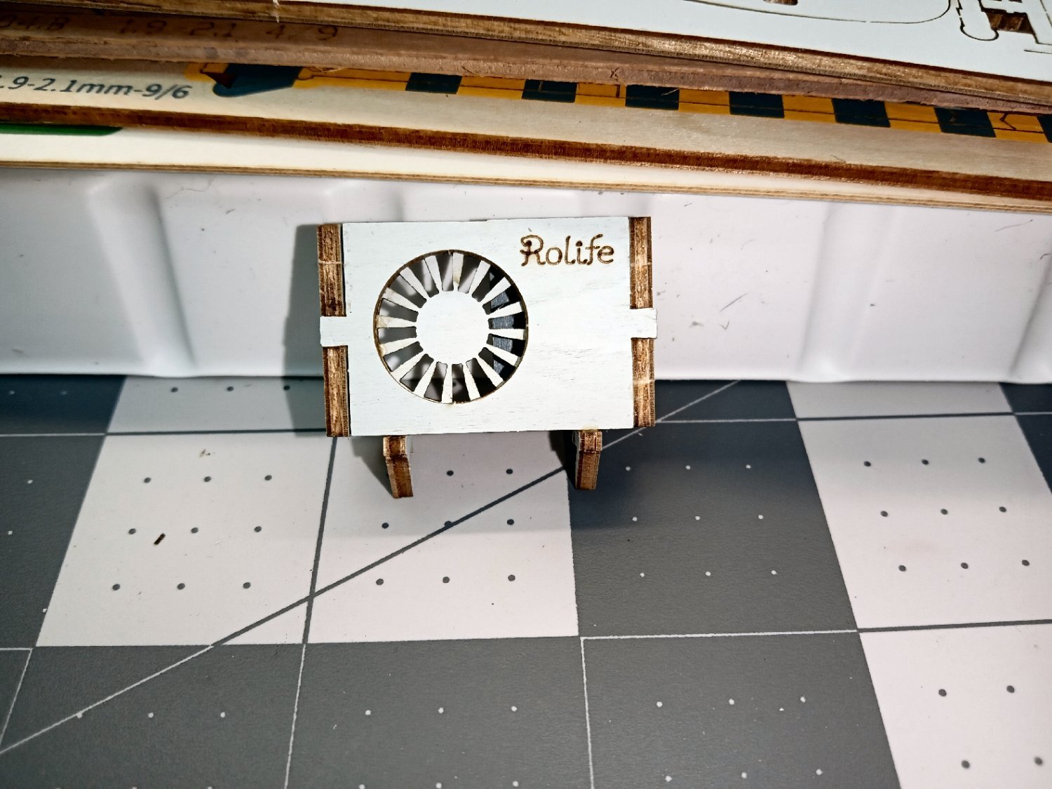
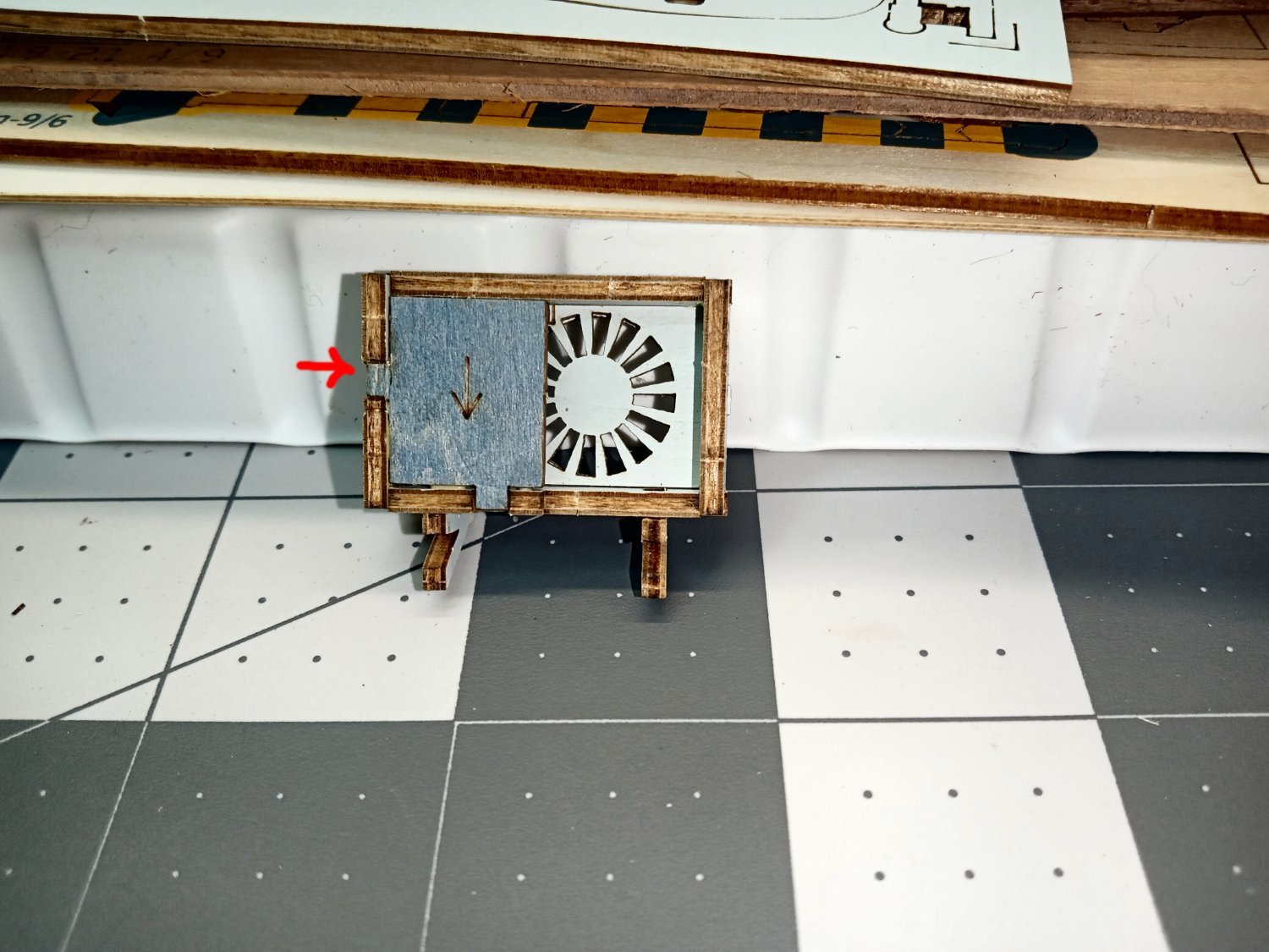
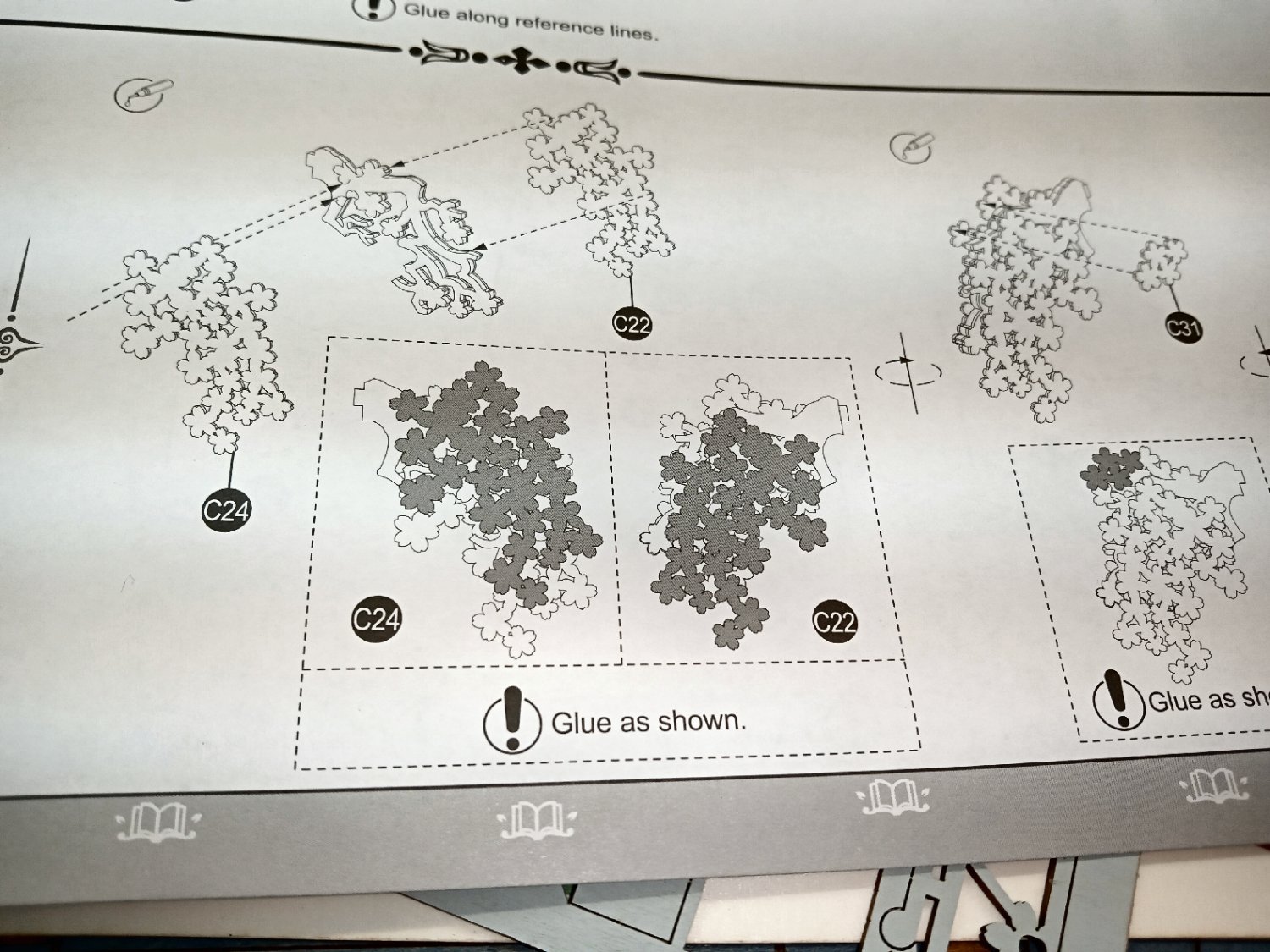
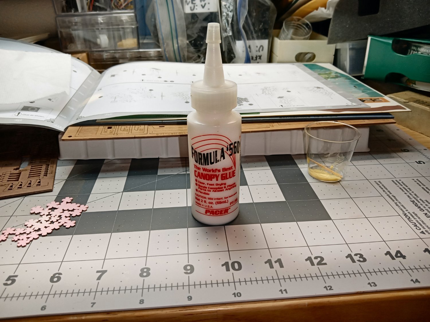
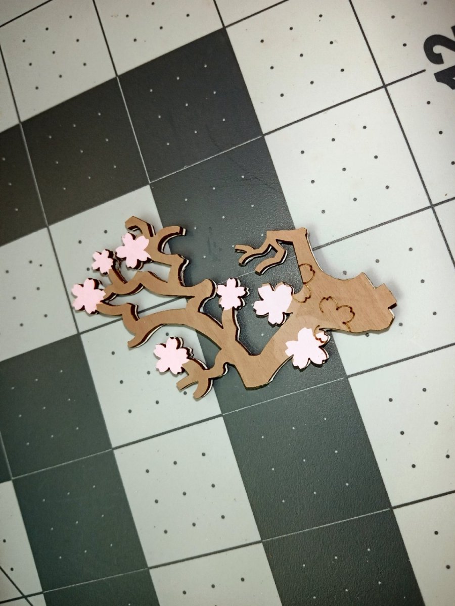
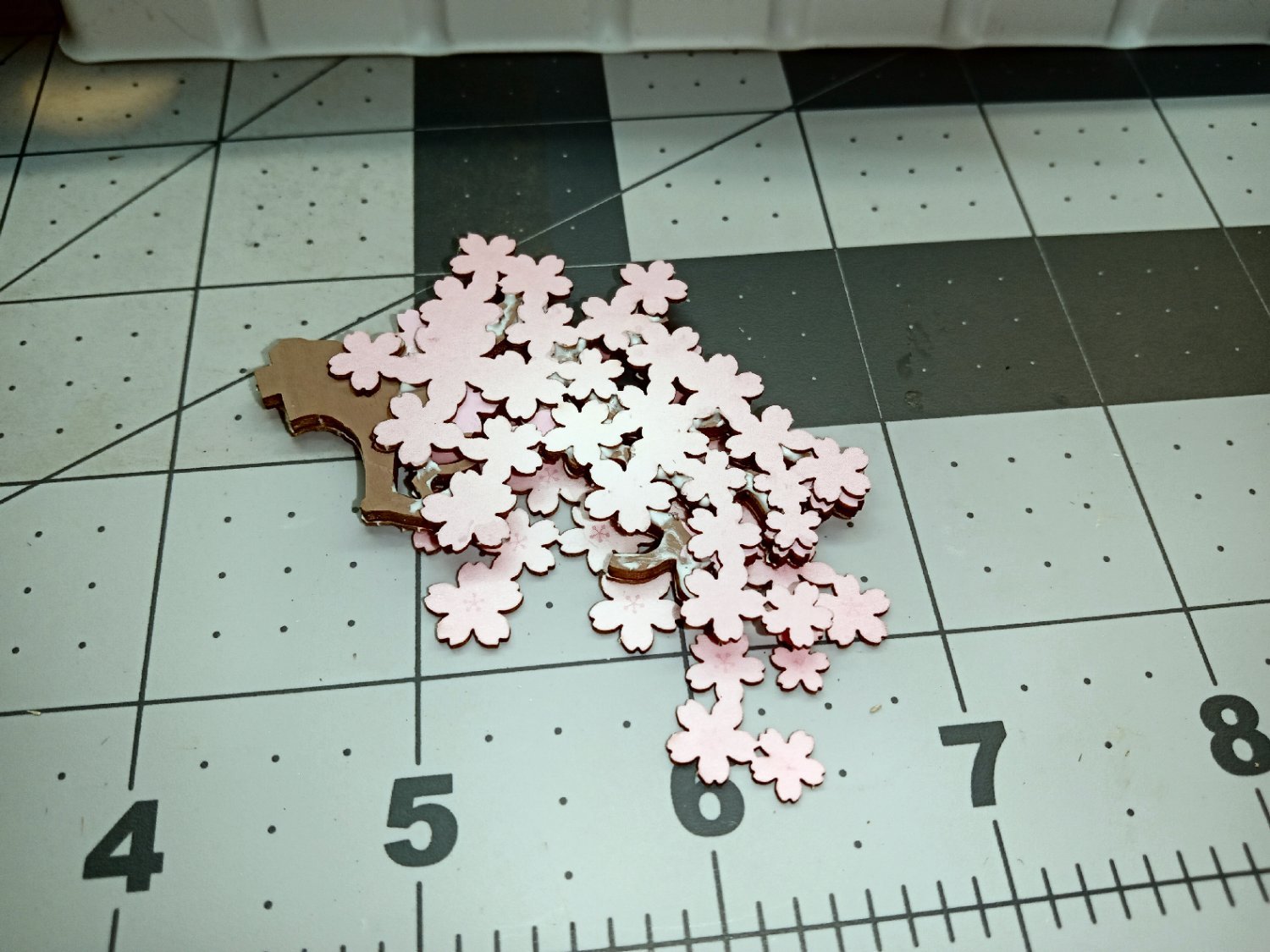
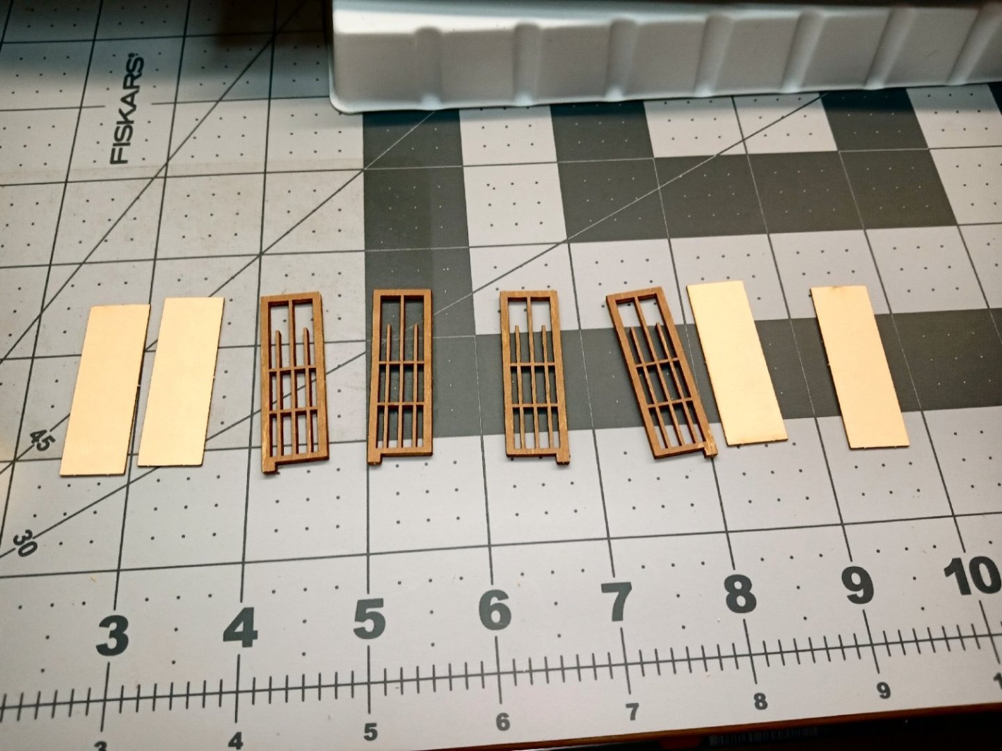
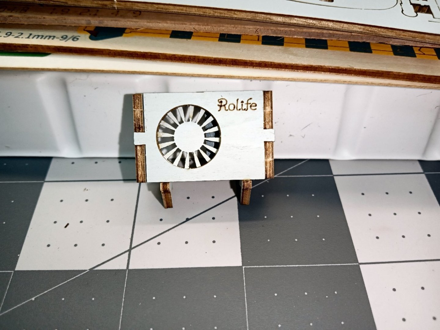
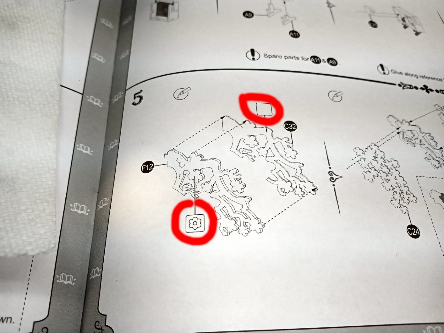
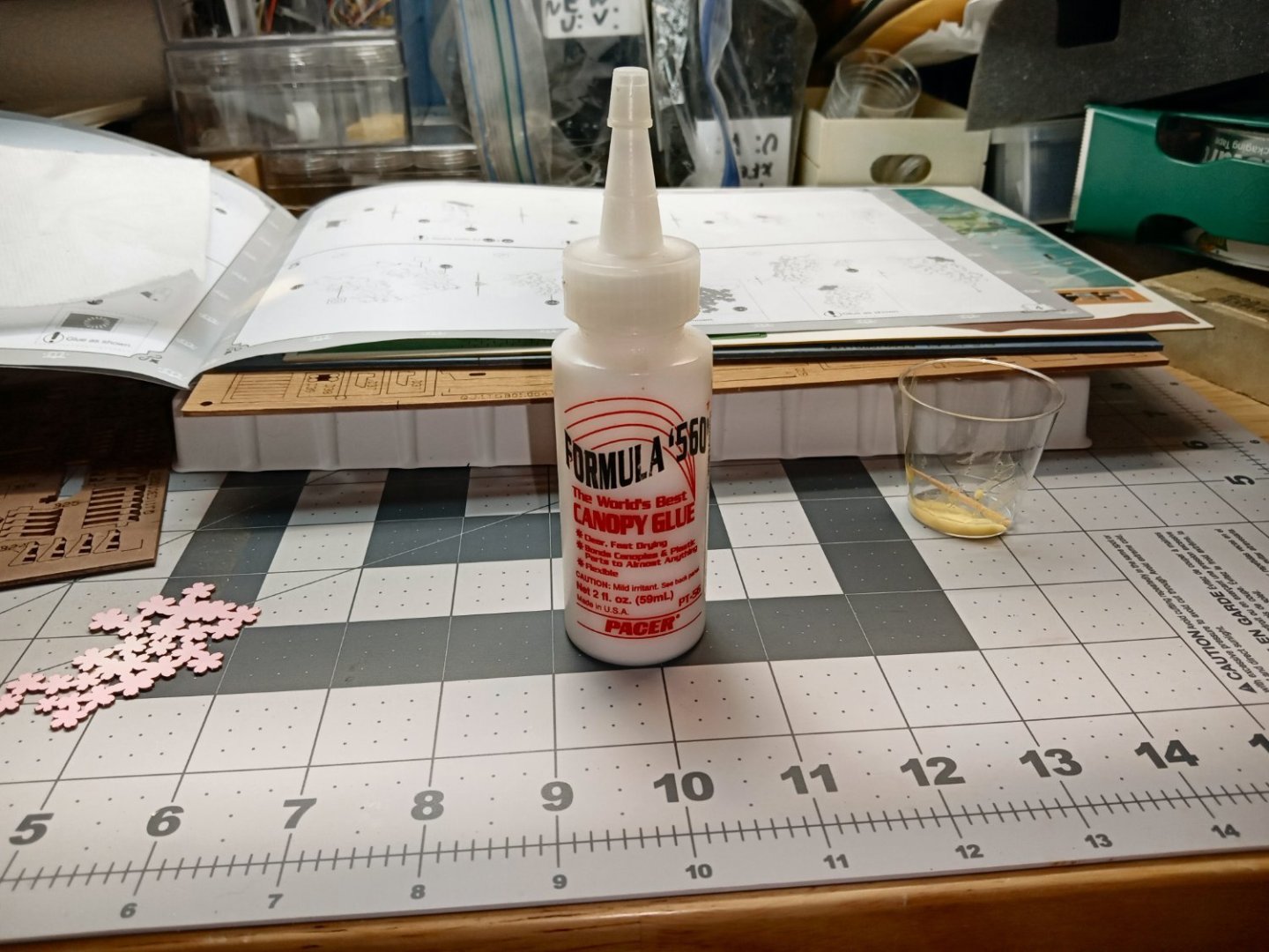
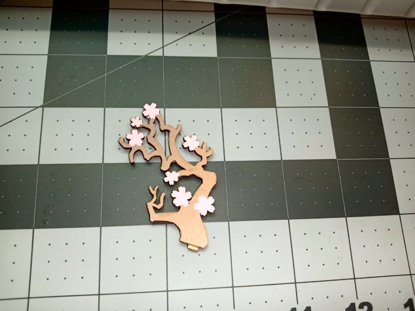
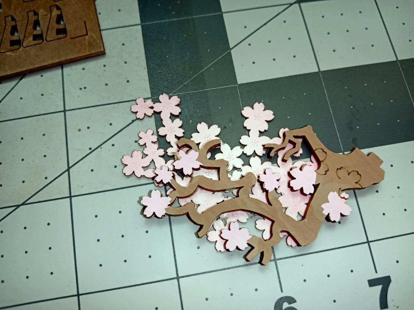
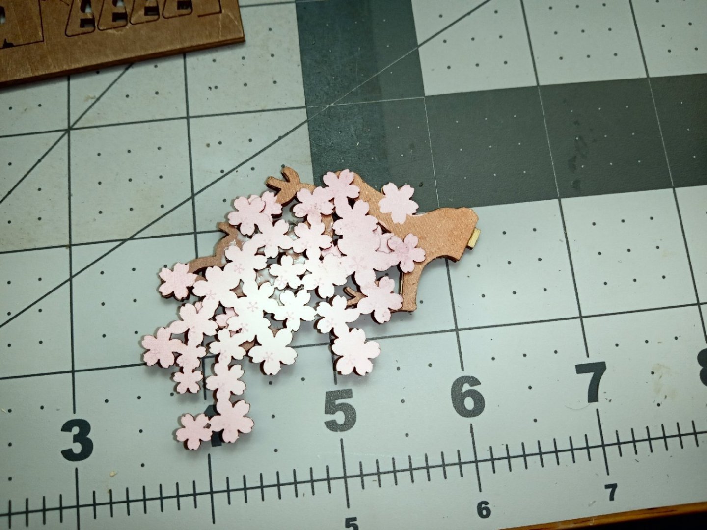
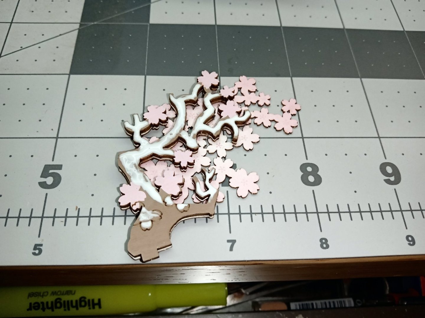
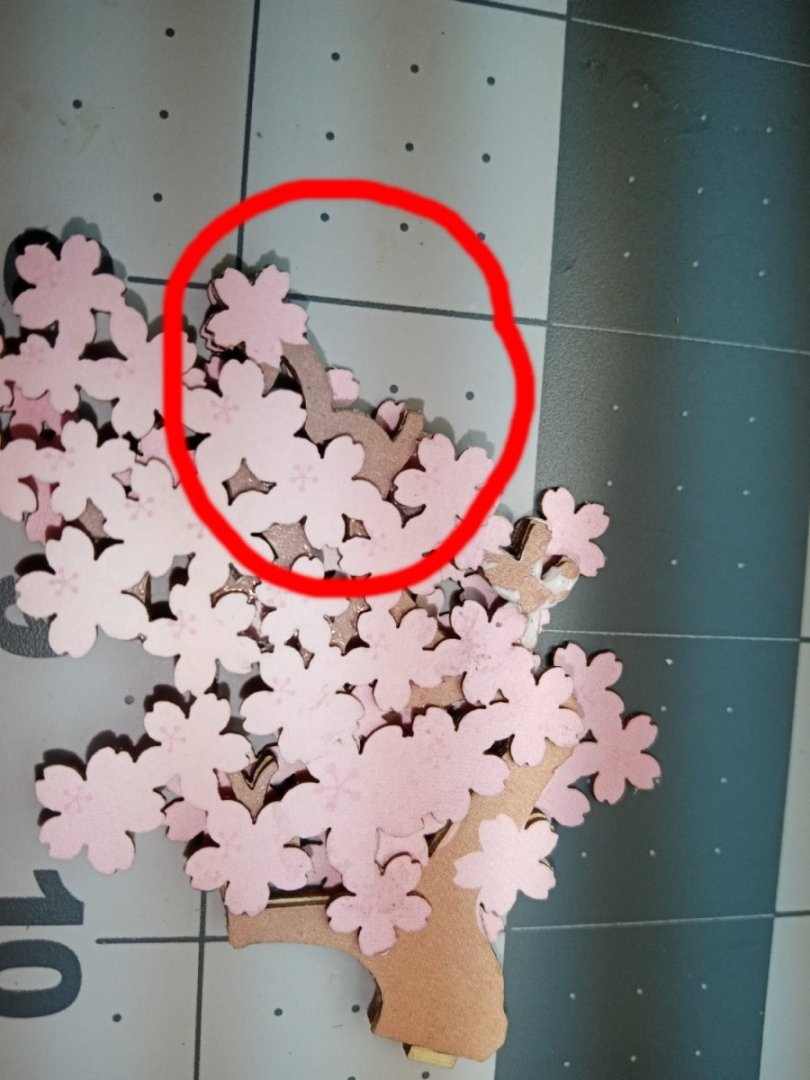
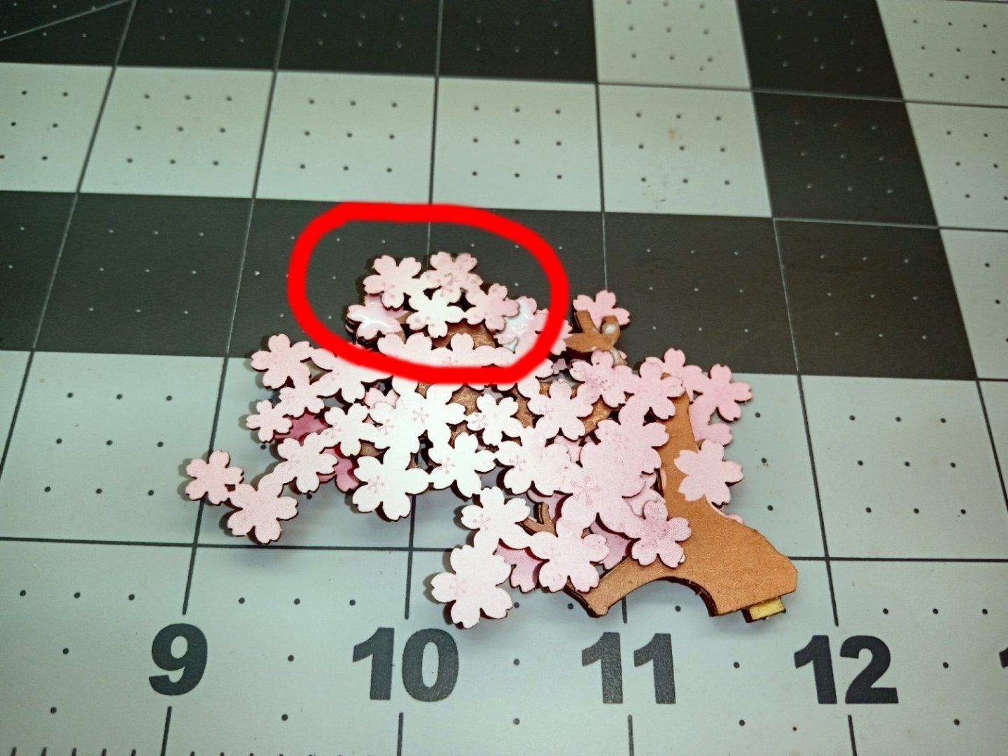
Part_002 Construction starts with four window assemblies. Four wooden frames are glued to printed cardboard backs. There are two sets, one with the bottom tab on the left, the other with the tabs on the right. The four panels are identical, so I picked the best side of each frame to be the front. The cardstock is printed on both sides, also, so I selected the best side of those four. The next part is a signpost with a roof over the sign. The construction is self-evident, the only thing to be careful of is that the textured side of the roof pieces is up. I did have to trim off the locating tab between one roof panel and the post, as the peak of the roof would not close with both tabs in place. This may be a problem in the future, as I had to trim off a tab on the next assembly also. The sign post only goes in one way, as the tabs are different sizes. The next item is the exterior compressor part of an air conditioner, that will eventually be mounted to a wall. The box is assembled with the front (outside face) panel and the four edge panels. Some care must be taken, as the parts are printed on both sides, so referencing the graphics in the instructions must be done. The bottom panel does not have different sized tabs to locate it, so I had to carefully look at the graphic. The panel that is the fan blades is glued inside the box, and two gray blocks behind that. The blocks represent the mechanical compressor parts. Here is where I had to trim off another tab on the rear most block. The block has an arrow etched on it to indicate the proper direction to mount it, but the tab that locks into the side panel does not line up! I cut off the tab, installed the piece, and then glued the tab into the side panel to fill the hole. Two supports are attached before the inside blocks are glued in place. Once again, I let my mind wonder, and broke the angled bracket off one of the supports. A little glue fixed the mistake. The next part is a multi-layer cherry tree. It starts with a wooden trunk, printed on one side, A printed cardstock backer is glued on the other side, to finish that side of the trunk. One thing to note about the instructions, if a part is printed on only one side the instructions indicate which is the printed or unprinted side facing you, by showing a square with either a blossom (printed side) or blank face. I’ve circled two examples in the picture below. For these parts where any excess glue would be seen, I used Canopy Glue instead of the yellow wood glue I normally use. The Canopy Glue is a high-quality white glue, specifically made to attach clear parts to other pieces, originally clear plane canopies to plastic models. It dries completely clear. I have also used it to glue parts to the bottom of clear cases. Several companies offer this type of glue, I’m using the one shown in the picture, because it was the one the local craft store carried. This is the original manufacturer of this type, but the other brands are just as good. This glue takes longer to set, though, so I leave the parts several hours to dry between layers. The glue also lasts a long time in the bottle. You may have to shake the bottle when you first start, like you would a bottle of paint. Several printed cardstock blossom layers are then glued to both sides the give depth to the tree. I had to take great care in orientating the blossom pieces, as there are location marks only for one of the several pieces. These pictures show both sides of the trunk. I spread the glue evenly over the entire surface of the cardstock side to ensure that there will not be any delamination in the future. I carefully scraped any excess glue off the edges, before it dried. I glued a cardstock blossom piece to one side of the trunk, then left it, blossom side up, to dry for a few hours. Once again, I spread the glue over the whole surface of the trunk where the blossoms attached, and used a toothpick to get rid of as much of the excess glue, as I could. Next, I glued the blossom piece to the other side. The first picture shows the glue spread on the contact surface of that side. The second shows the freshly attached part, with as much glue removed as I could. The difficulty of just getting the glue where needed, and not on other areas, is why I wanted the canopy glue for this. The last piece needed for the tree is a small blossom group to go over the section in the picture below where the circled branch area is shown. Here is the four-blossom group installed


- 25 replies
-
- 11
-
-
I would stick a wood block between the head and table, and run the head down to lock the block in place, also. If it is really stuck, you might damage the ways (the piece the head slides on), or the head if you have to hit it hard. These are small machines.
-
The build on this will start in a week or so, I was concentrating on finishing a set of 3D printable cannon files, a few day side job, and family business problems.
-
3D Printing Cannons in Resin
thibaultron replied to thibaultron's topic in 3D-Printing and Laser-Cutting.
Blomefield Pattern about 1787 STL Files Blomefield Pattern 6 Pounder 84 1_24 Size_99_39mm.stl Blomefield Pattern 6 Pounder 90 Full Size_2554_42mm.stl Blomefield Pattern 6 Pounder 102 Full Size_2873_90mm.stl Blomefield Pattern 9 Pounder 90 Full Size_2413_63mm.stl Blomefield Pattern 9 Pounder 102 Full Size_2873_90mm.stl Blomefield Pattern 9 Pounder 108 Full Size_3031_86mm.stl Blomefield Pattern 12 Pounder 90 Full Size_2553_49mm.stl Blomefield Pattern 12 Pounder 102 Full Size_2873_90mm.stl Blomefield Pattern 18 Pounder 108 Full Size_3031_86mm.stl Blomefield Pattern 18 Pounder 114 Full Size_3183_60mm.stl Blomefield Pattern 24 Pounder 108 Full Size_3031_86mm.stl Blomefield Pattern 24 Pounder 114 Full Size_3183_60mm.stl Blomefield Pattern 32 Pounder 114 Size_3183_47mm.stl Blomefield Pattern 12 Pounder 108 Full Size_3031_86mm.stl -
3D Printing Cannons in Resin
thibaultron replied to thibaultron's topic in 3D-Printing and Laser-Cutting.
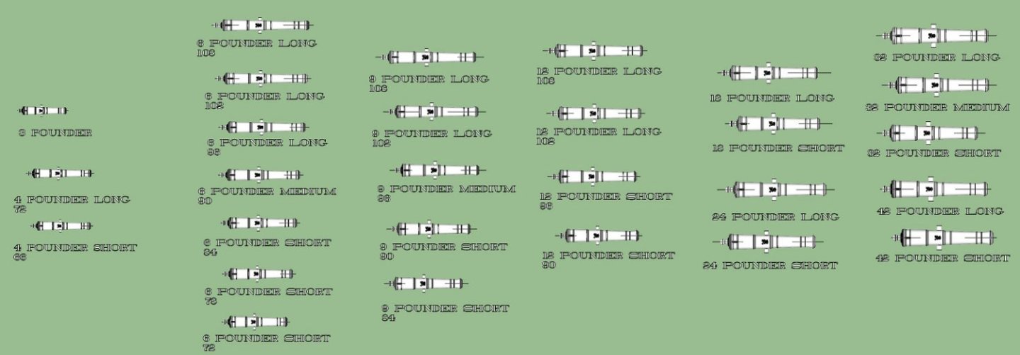
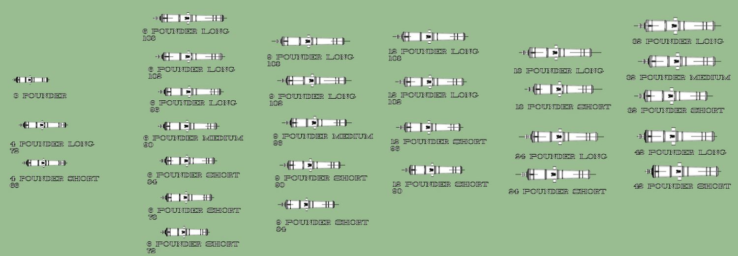
OK, the NRG class today starts an hour later than I thought, so here is the Blomefield info. These are the only sizes I had drawings for. Blomefield Pattern about 1787 Graphics 6 Pounder 84 6 Pounder 90 6 Pounder 102 9 Pounder 90 9 Pounder 102 9 Pounder 108 12 Pounder 90 12 Pounder 102 12 Pounder 108 18 Pounder 108 18 Ponder 114 24 Pounder 108 24 Pounder 114 32 Pounder 114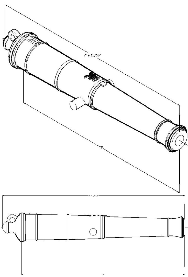


-
A story I heard, about 50 years ago. I worked in a defense industry, designing military radars. Gray is a very difficult color to mix consistently between batches, even commercially, Well a high ranking officer got a bug up his rear, and decided to check one type of equipment color as compared to the official paint chip he had. Sure enough none to the field equipment matched, and he went into a tirade! He demanded all that type of equipment be repainted, to match the paint chips he handed out! He said he would be back in X amount of time, and check again. Dire consequences were promised! Well the time came, and he returned. All but one of the equipment at the various locations failed, but one! Afterwards, the other locations call the successful one and asked how he had managed to match the paint chip he was given. He told them he repainted his chip at the same time he repainted the equipment!
- 13 replies
-
- 11
-

-
-
3D Printing Cannons in Resin
thibaultron replied to thibaultron's topic in 3D-Printing and Laser-Cutting.
I will be posting the Blomefield Cannons later today, or tomorrow. I have to create the Brown Pattern Cannon graphics, so they will be posted later this week, the STL files are finished. -
3D Printing Cannons in Resin
thibaultron replied to thibaultron's topic in 3D-Printing and Laser-Cutting.
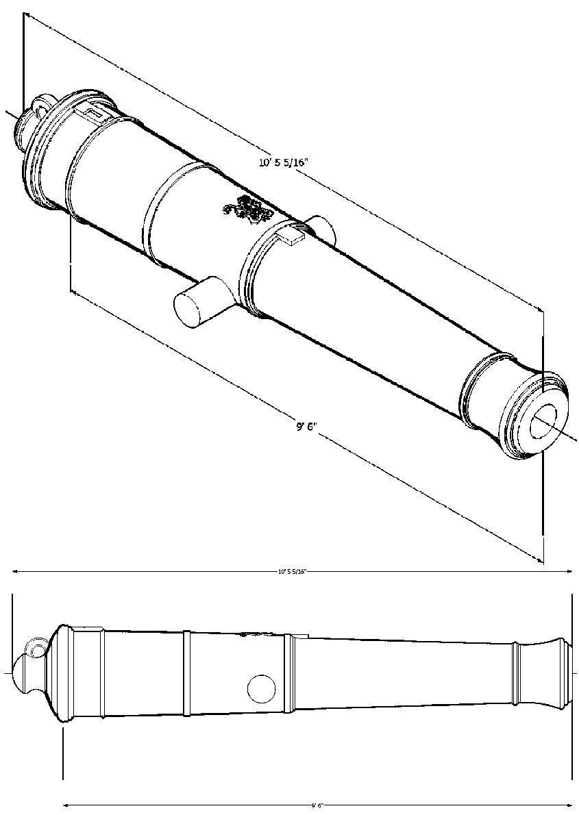
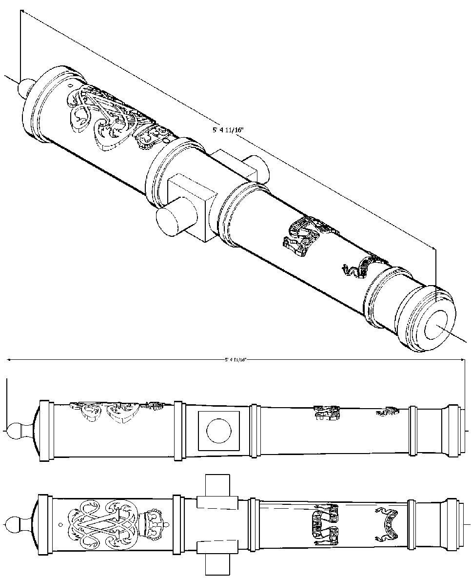
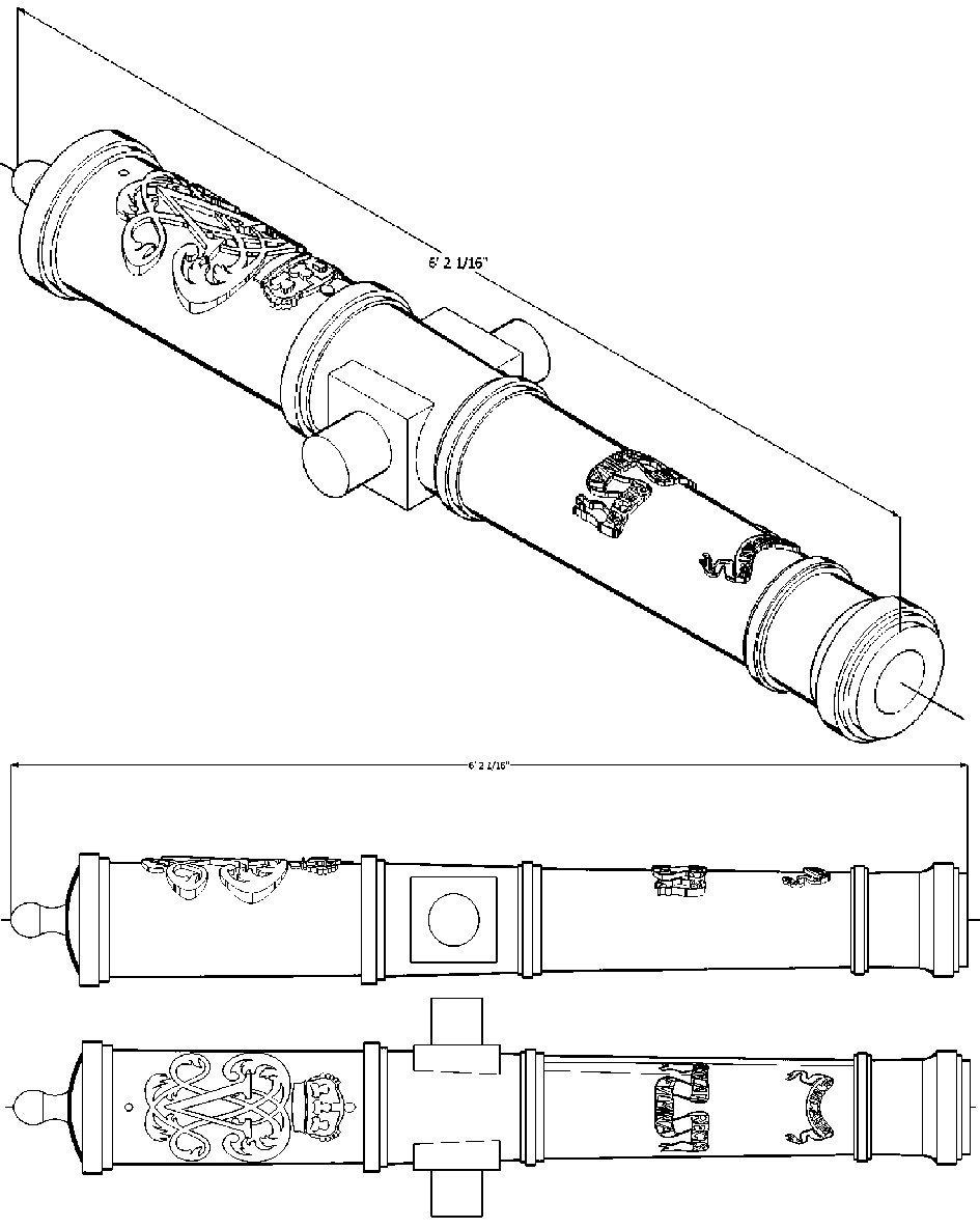
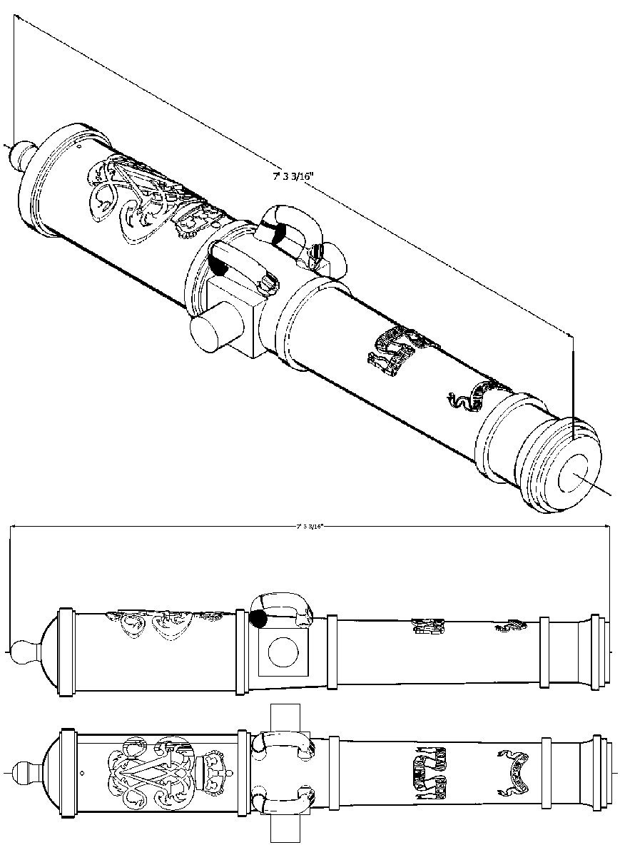
Spanish Cannons 1718 Pattern STLs . Spanish 5 Pounder Cannon 1718 Pattern Full Size_1642_27mm.stl Spanish 9 Pounder Cannon 1718 Pattern Full Size_1880_92mm.stl Spanish 12 Pounder Cannon 1718 Pattern Full Size_2214_83mm.stl Spanish 16 Pounder Cannon 1718 Pattern Full Size_3009_77mm.stl Spanish 24 Pounder Cannon 1718 Pattern Full Size_3353_46mm.stl -
3D Printing Cannons in Resin
thibaultron replied to thibaultron's topic in 3D-Printing and Laser-Cutting.
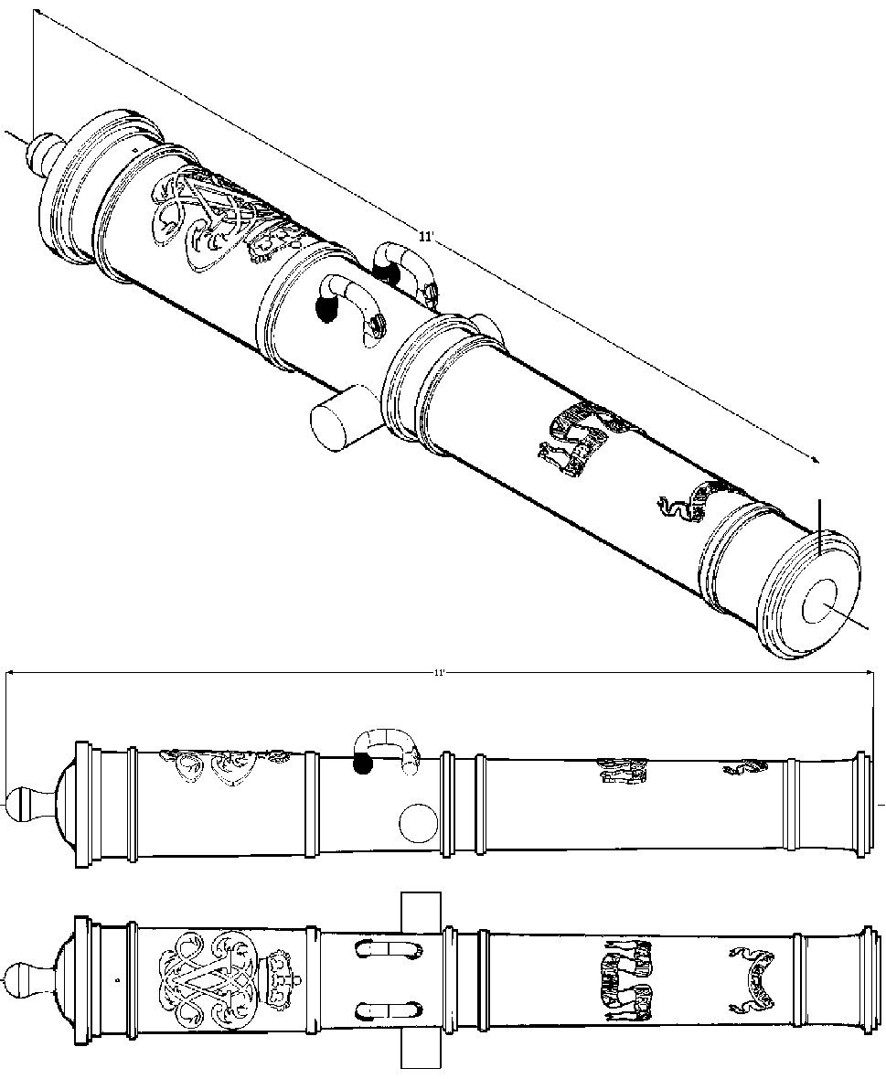
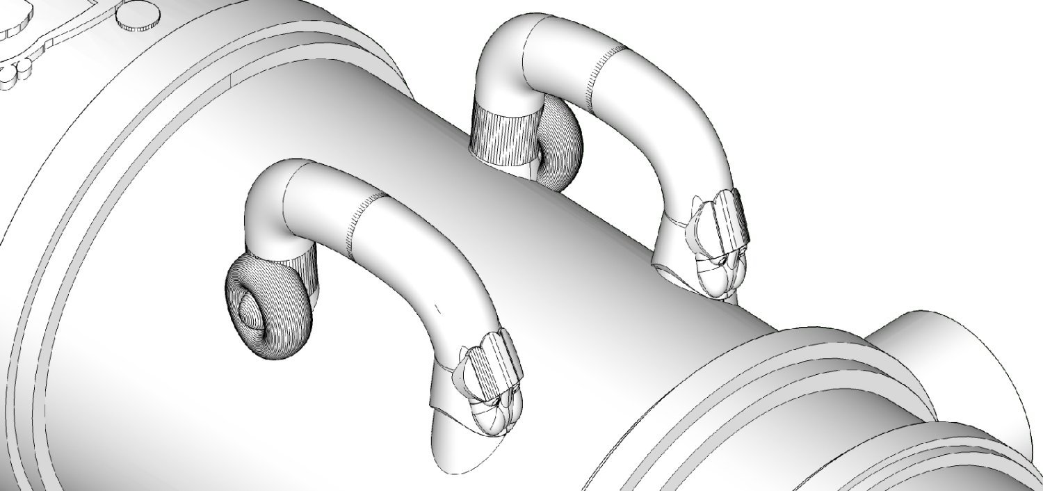
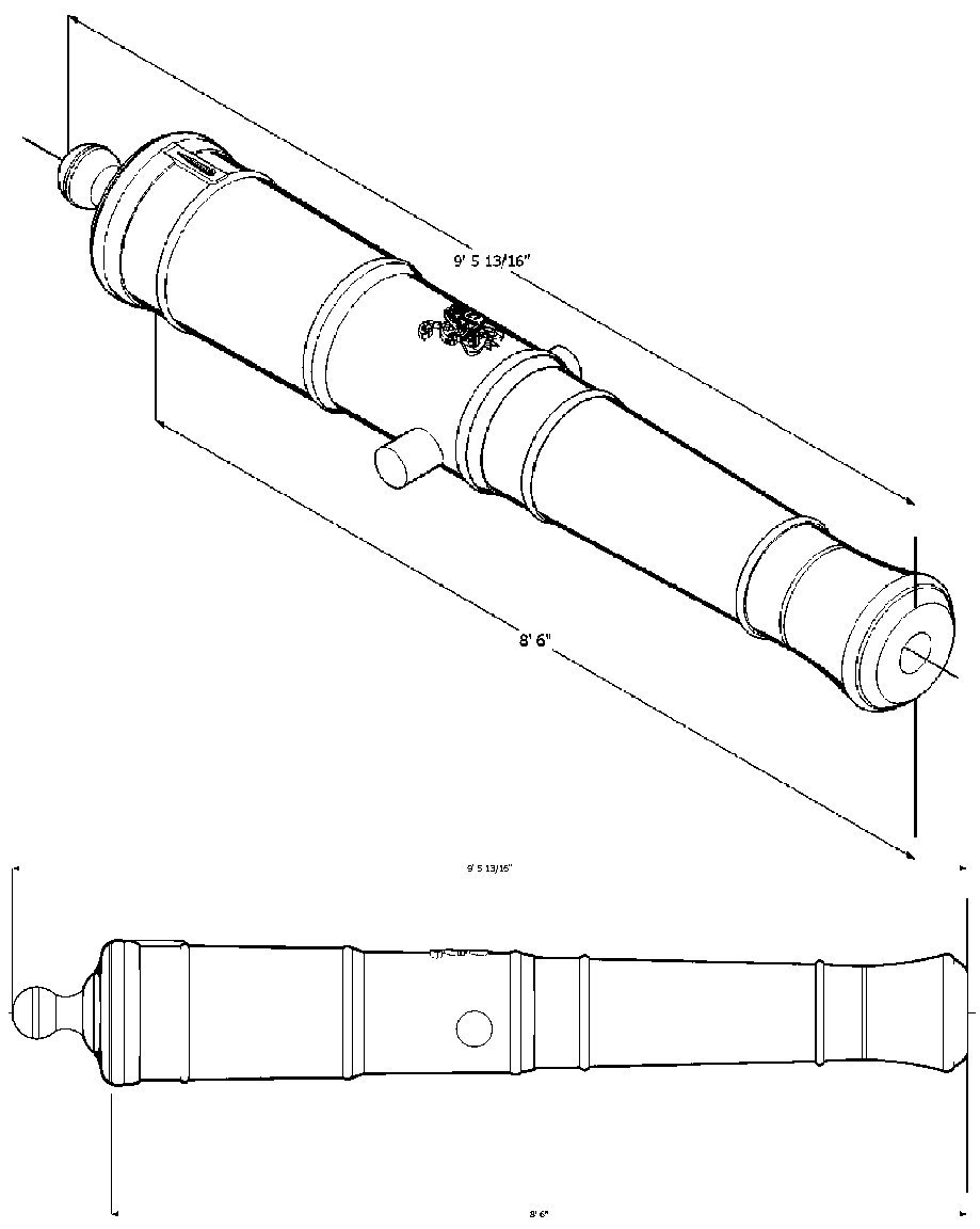
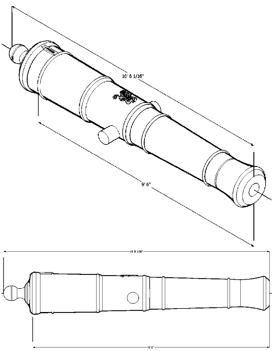
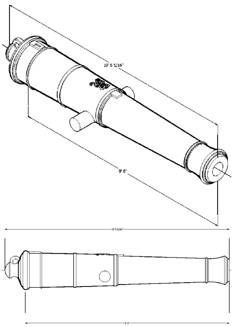
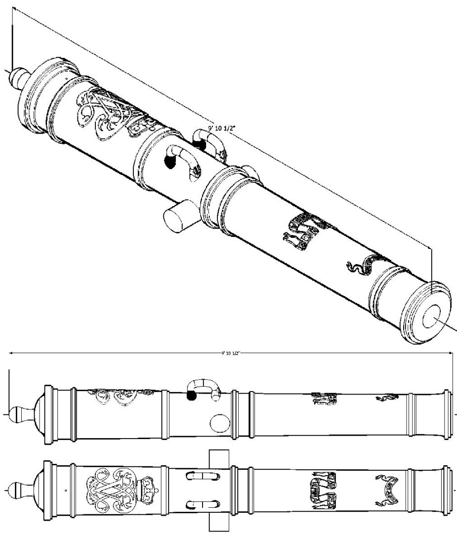
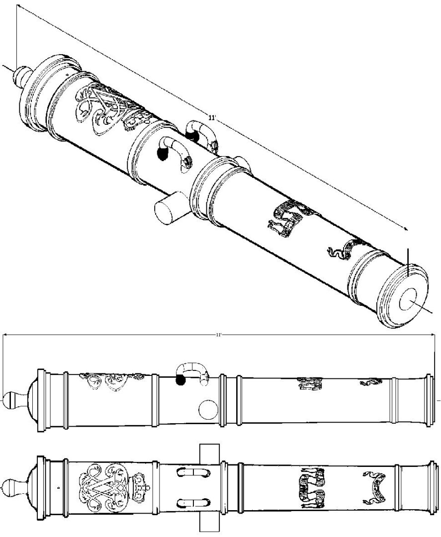
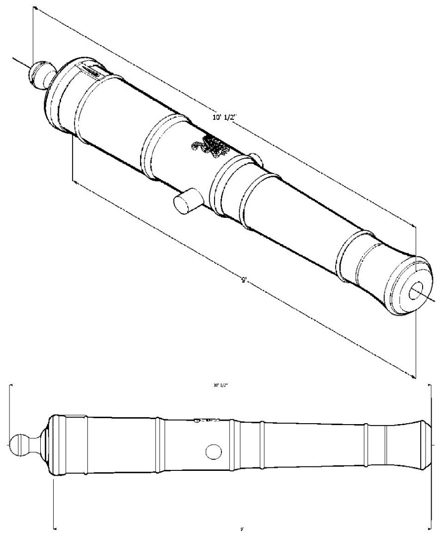
Spanish Cannons 1718 Pattern Graphics. I did not include the barrel length, as I only had drawings for one of each size. The Royal scroll and the cannon name scroll are on the barrel, but I will admit that the cannon name is the same for each STL, rather than individual names, as on the real cannon. I could only find one good photograph or drawing of this feature to trace. Yes the larger size cannons did not have the box structure at the trunions. No, I have no idea why. The handles are my best attempt at a Sea Monster motif. 5 Pounder 9 Pounder 12 Pounder 16 Pounder 24 Pounder


-
3D Printing Cannons in Resin
thibaultron replied to thibaultron's topic in 3D-Printing and Laser-Cutting.
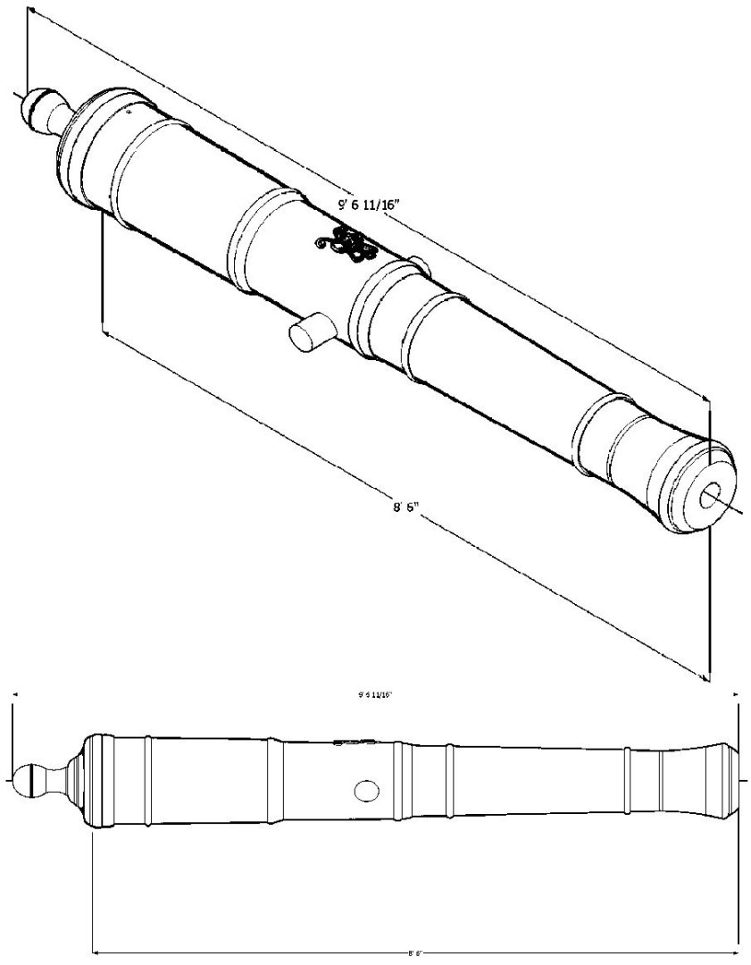
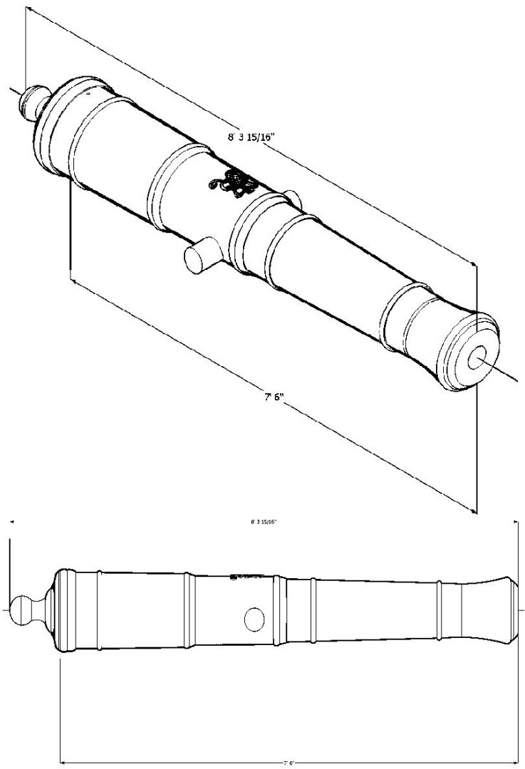
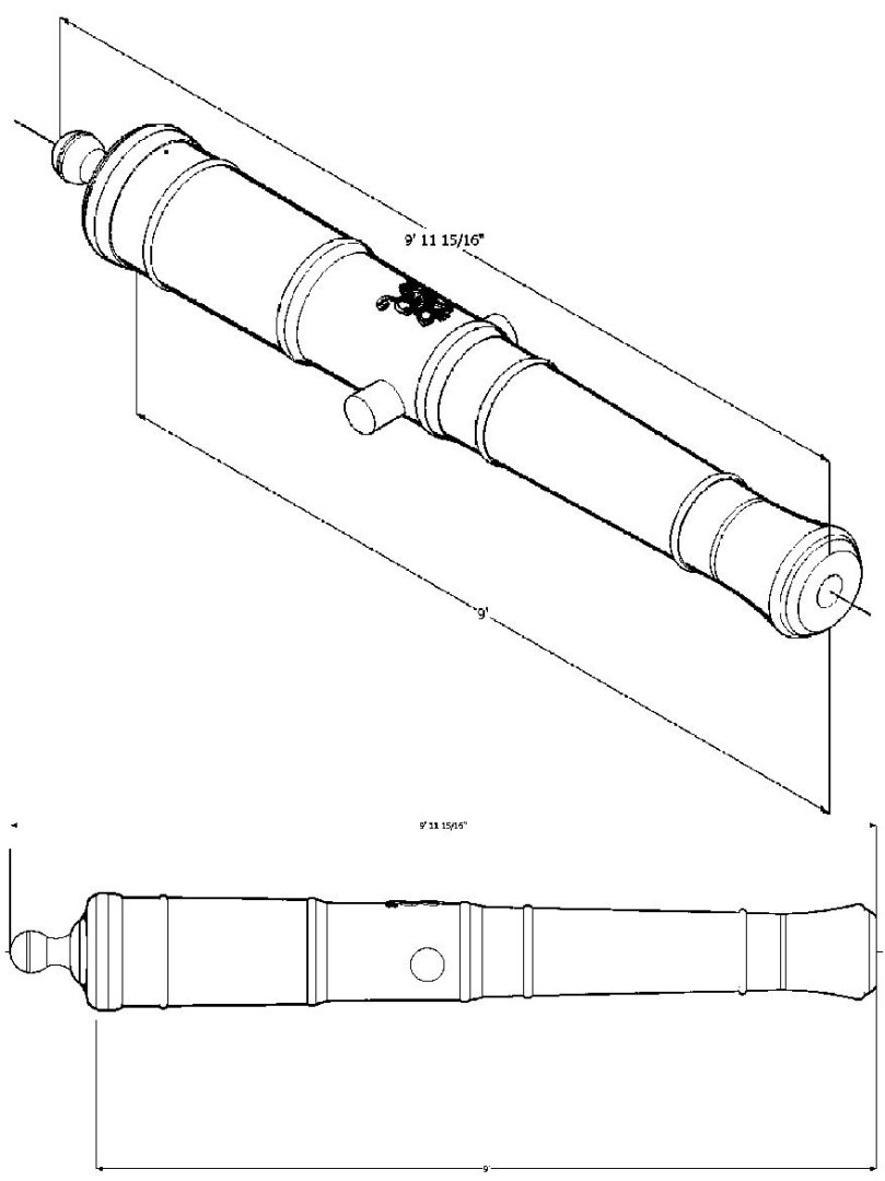
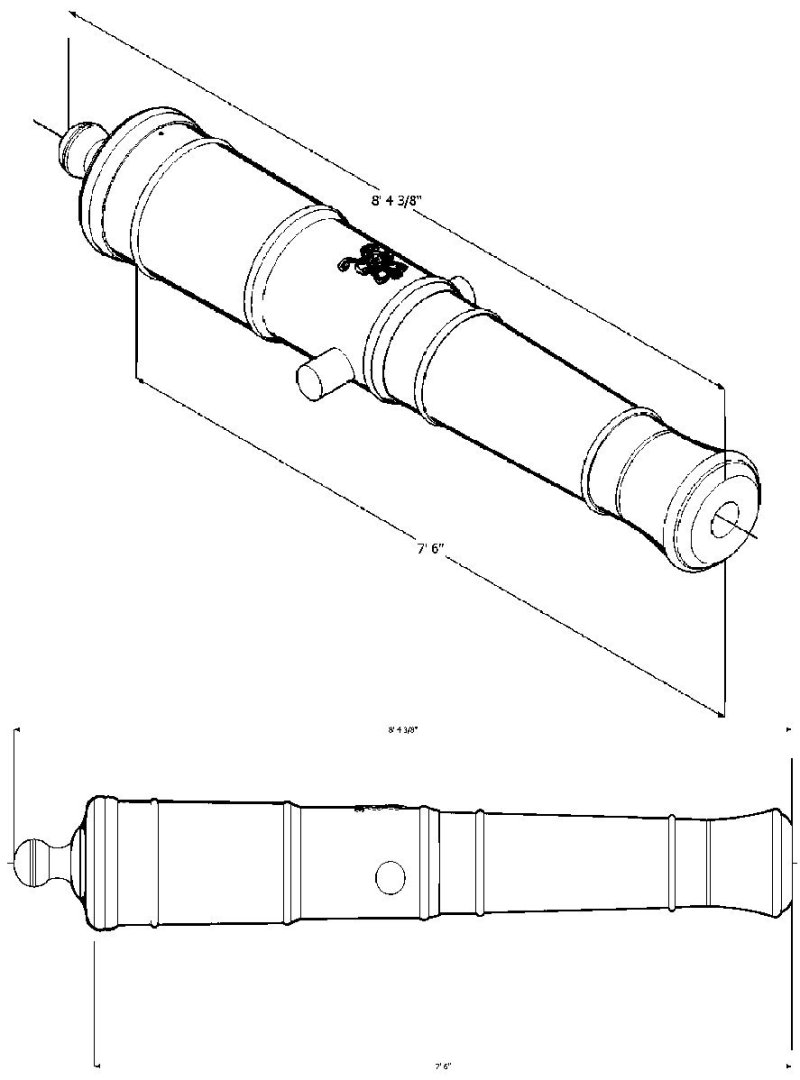
The Armstrong-Fredricks Cannon STLs - Part 2 Armstrong Fredrick Pattern 12 Pounder 102 Full Size_2890_31mm.stl Armstrong Fredrick Pattern 12 Pounder 108 Full Size_3060_30mm.stl Armstrong Fredrick Pattern 18 Pounder 108 Full Size_3099_59mm.stl Armstrong Fredrick Pattern 24 Pounder 108 Full Size_3080_94mm.stl Armstrong Fredrick Pattern 24 Pounder 114 Full Size_3252_13mm.stl Armstrong Fredrick Pattern 32 Pounder 114 Full Size_3252_13mm.stl Armstrong Fredrick Pattern 32 Pounder 120 Full Size_3423_31mm.stl Armstrong Fredrick Pattern 42 Pounder 114 Full Size_3234_00mm.stl Armstrong Fredrick Pattern 42 Pounder 120_Full Size_3404_26mm.stl -
3D Printing Cannons in Resin
thibaultron replied to thibaultron's topic in 3D-Printing and Laser-Cutting.
The Armstrong-Fredricks Cannon STLs - Part 1 Armstrong Fredrick Pattern 3 Pounder 54 Full Size_1542_39mm.stl Armstrong Fredrick Pattern 4 Pounder 66 Full Size_1885_16mm.stl Armstrong Fredrick Pattern 4 Pounder 72 Full Size_2056_47mm.stl Armstrong Fredrick Pattern 6 Pounder 72 Full Size_2056_47mm.stl Armstrong Fredrick Pattern 6 Pounder 78 Full Size_2227_92mm.stl Armstrong Fredrick Pattern 6 Pounder 84 Full Size_2399_24mm.stl Armstrong Fredrick Pattern 6 Pounder 90 Full Size_2570_56mm.stl Armstrong Fredrick Pattern 6 Pounder 96 Full Size_2742_01mm.stl Armstrong Fredrick Pattern 6 Pounder 102 Full Size_2913_33mm.stl Armstrong Fredrick Pattern 6 Pounder 108 Full Size_3084_78mm.stl Armstrong Fredrick Pattern 9 Pounder 84 Full Size_2368_81mm.stl Armstrong Fredrick Pattern 9 Pounder 90 Full Size_2538_15mm.stl Armstrong Fredrick Pattern 9 Pounder 96 Full Size_2707_35mm.stl Armstrong Fredrick Pattern 9 Pounder 102 Full Size_2876_55mm.stl Armstrong Fredrick Pattern 9 Pounder 108 Full Size_3045_75mm.stl Armstrong Fredrick Pattern 12 Pounder 90 Full Size_2550_32mm.stl -
3D Printing Cannons in Resin
thibaultron replied to thibaultron's topic in 3D-Printing and Laser-Cutting.
The Armstrong-Fredricks Cannon Graphics - Part 2 12 Pounder 102 12 Pounder 108 18 Pounder 108 24 pounder 108 24 Pounder 114 32 Pounder 114 32 Pounder 120 42 Pounder 114 42 Pounder 120


-
3D Printing Cannons in Resin
thibaultron replied to thibaultron's topic in 3D-Printing and Laser-Cutting.
The Armstrong-Fredricks Cannon Graphics - Part 1 3 Pounder 54 4 Pounder 66 4 Pounder - 72 6 Pounder 72 6 Pounder 78 6 Pounder 84 6 pounder 90 8 Pounder 96 6 pounder 102 6 Pounder 108 9 Pounder 84 9 Pounder 90 9 Pounder 96 9 Pounder 102 9 Pounder 108 12 Pounder 90


-
3D Printing Cannons in Resin
thibaultron replied to thibaultron's topic in 3D-Printing and Laser-Cutting.
Armstrong STL files Part 1 Armstrong Pattern 18 Pounder 96 Full Size_2755_24mm.stl Armstrong Pattern 18 Pounder 108 Full Size_3100_23mm.stl Armstrong Pattern 24 Pounder 108 Full Size_3080_94mm.stl Armstrong Pattern 24 Pounder 114 Full Size_3252_13mm.stl Armstrong Pattern 32 Pounder 114 Full Size_3252_13mm.stl Armstrong Pattern 32 Pounder 120 Full Size_3423_31mm.stl Armstrong Pattern 42 Pounder 114 Full Size_3234_00mm.stl Armstrong Pattern 42 Pounder 120 Full Size_3404_26mm.stl -
3D Printing Cannons in Resin
thibaultron replied to thibaultron's topic in 3D-Printing and Laser-Cutting.
Armstrong STL files Part 1 Armstrong Pattern 3 Pounder 54 Full Size_1542_39mm.stl Armstrong Pattern 4 Pounder 60 Full Size_1713_71mm.stl Armstrong Pattern 4 Pounder 72 Full Size_2056_47mm.stl Armstrong Pattern 6 Pounder 72 Full Size_2056_47mm.stl Armstrong Pattern 6 Pounder 78 Full Size_2227_92mm.stl Armstrong Pattern 6 Pounder 84 Full Size_2399_24mm.stl Armstrong Pattern 6 Pounder 90 Full Size_2570_56mm.stl Armstrong Pattern 6 Pounder 96 Full Size_2742_01mm.stl Armstrong Pattern 6 Pounder 102 Full Size_2913_33mm.stl Armstrong Pattern 9 Pounder 84 Full Size_2368_81mm.stl Armstrong Pattern 9 Pounder 90 Full Size_2538_15mm.stl Armstrong Pattern 9 Pounder 102 Full Size_2876_55mm.stl Armstrong Pattern 9 Pounder 108 Full Size_3045_75mm.stl Armstrong Pattern 12 Pounder 90 Full Size_2550_32mm.stl Armstrong Pattern 12 Pounder 102 Full Size_2890_31mm.stl Armstrong Pattern 12 Pounder 108 Full Size_3060_30mm.stl -
3D Printing Cannons in Resin
thibaultron replied to thibaultron's topic in 3D-Printing and Laser-Cutting.
Those are the factoes I used when following the spec on the site I listed. -
3D Printing Cannons in Resin
thibaultron replied to thibaultron's topic in 3D-Printing and Laser-Cutting.
Armstrong Cannon Graphics - Part 1. 18 Pounder 96 18 Pounder 108 24 Pounder 108 24 Pounder 114 32 Pounder 114 32 Pounder 120 42 Pounder 114 42 Pounder 120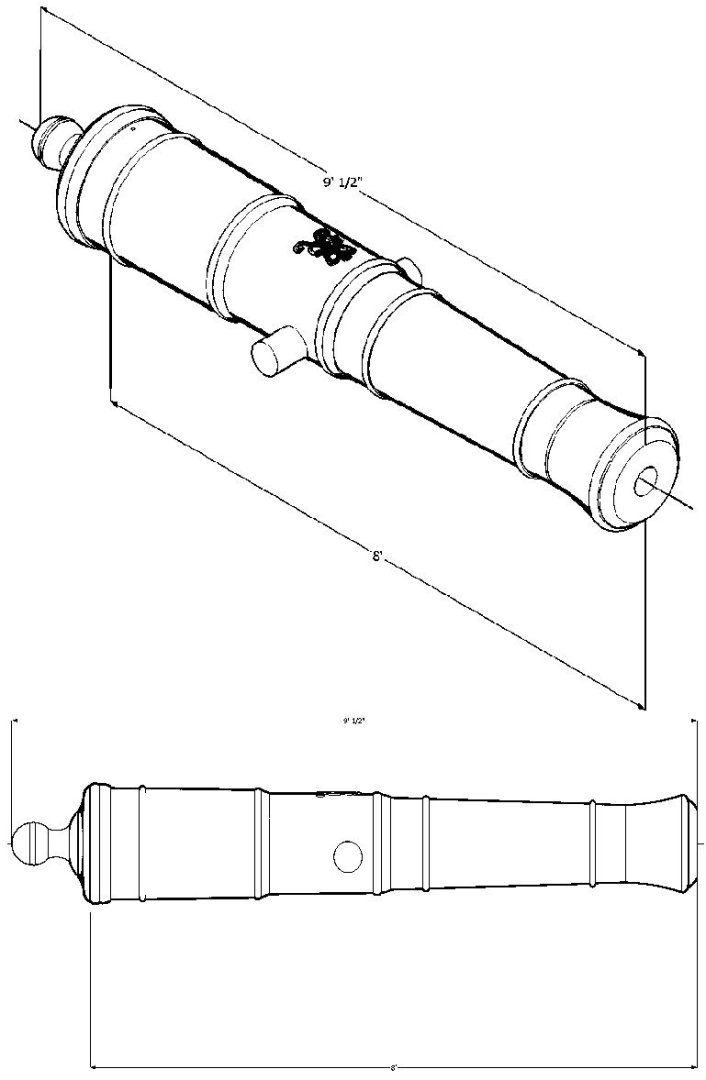


-
3D Printing Cannons in Resin
thibaultron replied to thibaultron's topic in 3D-Printing and Laser-Cutting.
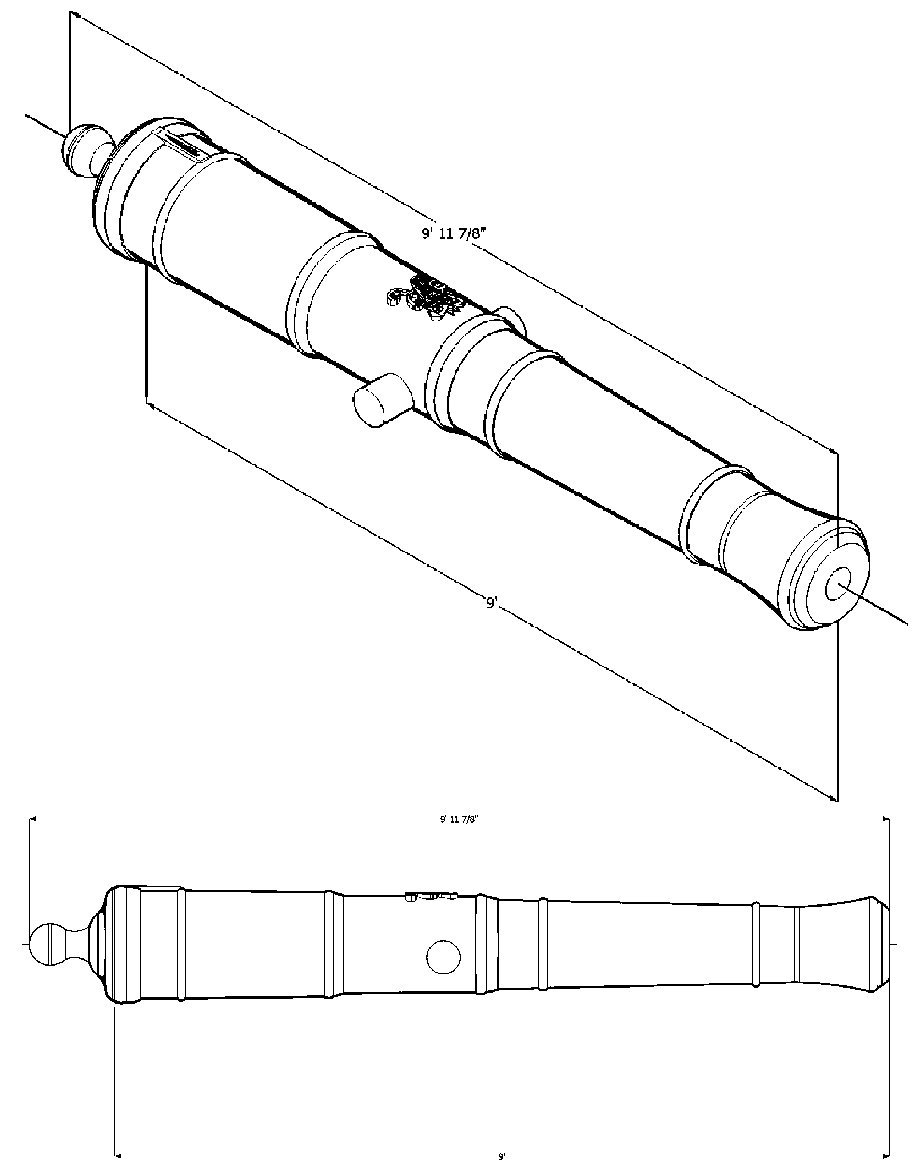
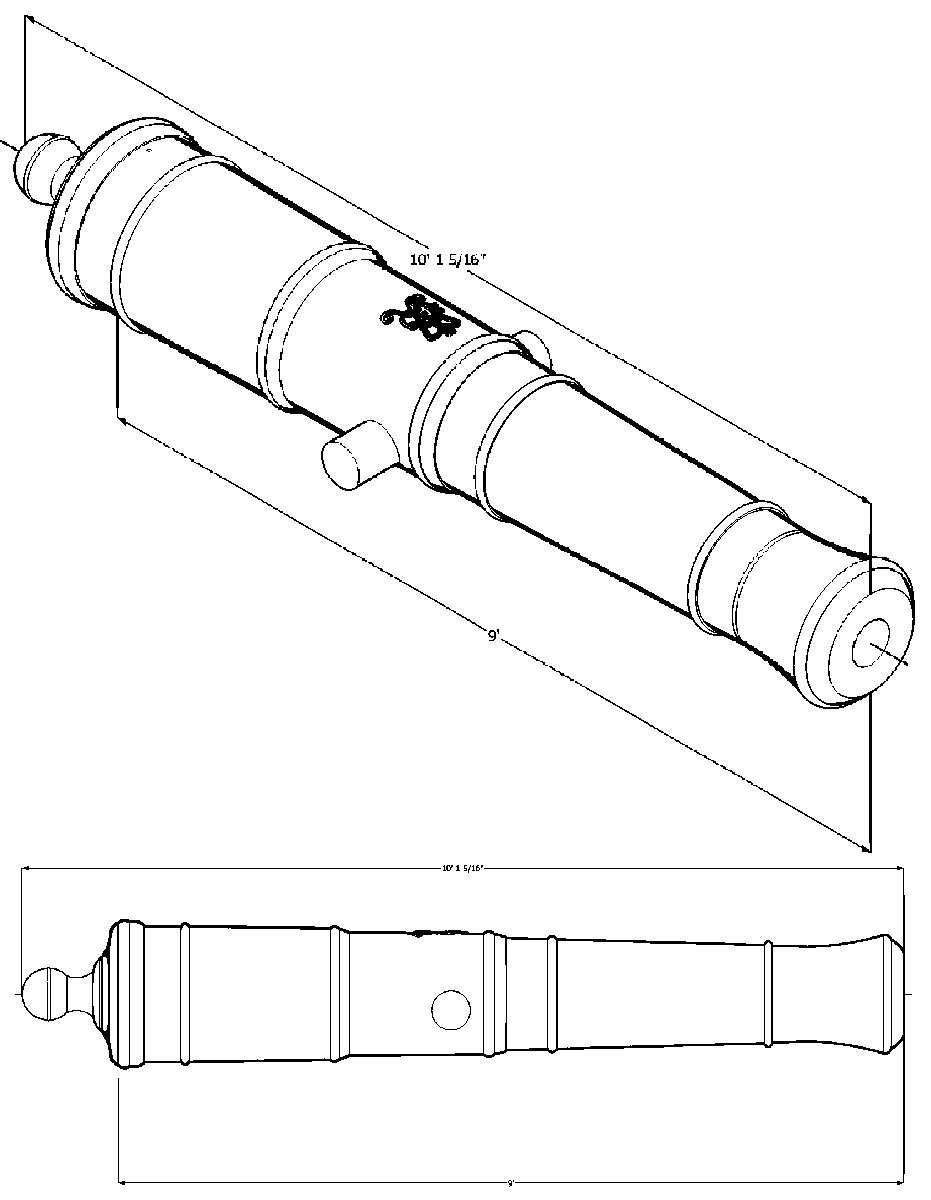
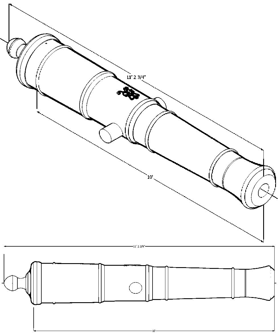
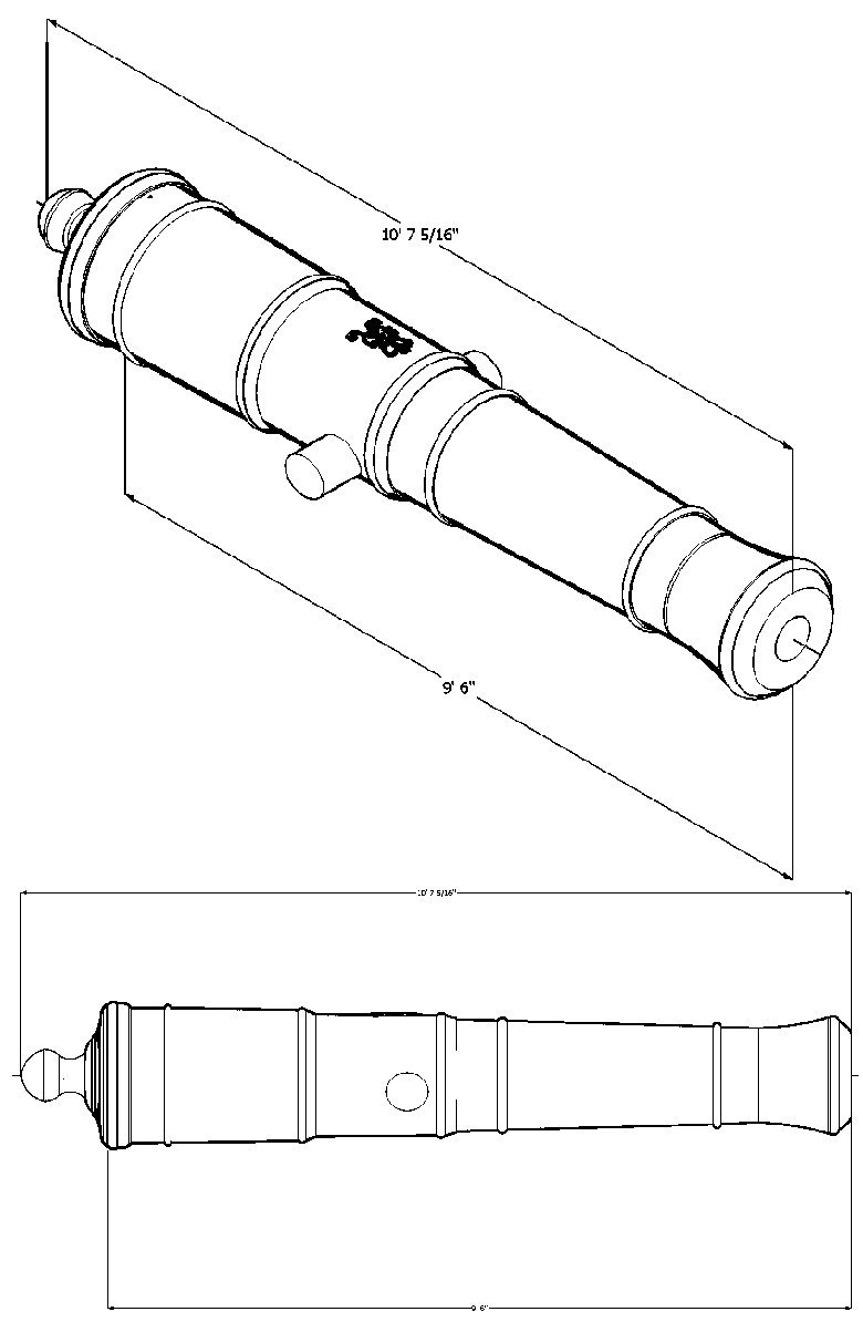
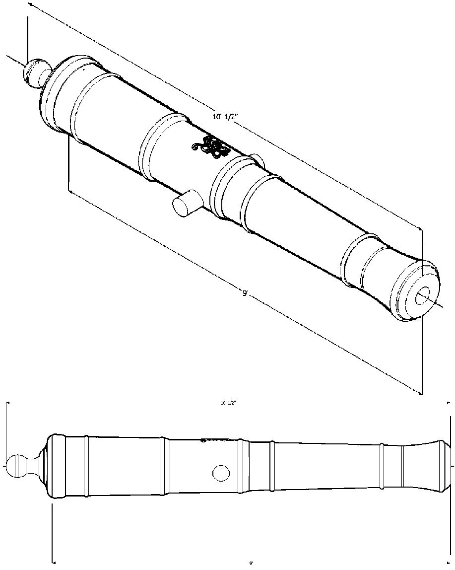
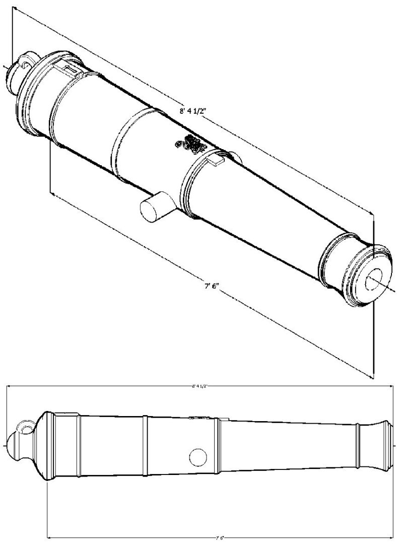
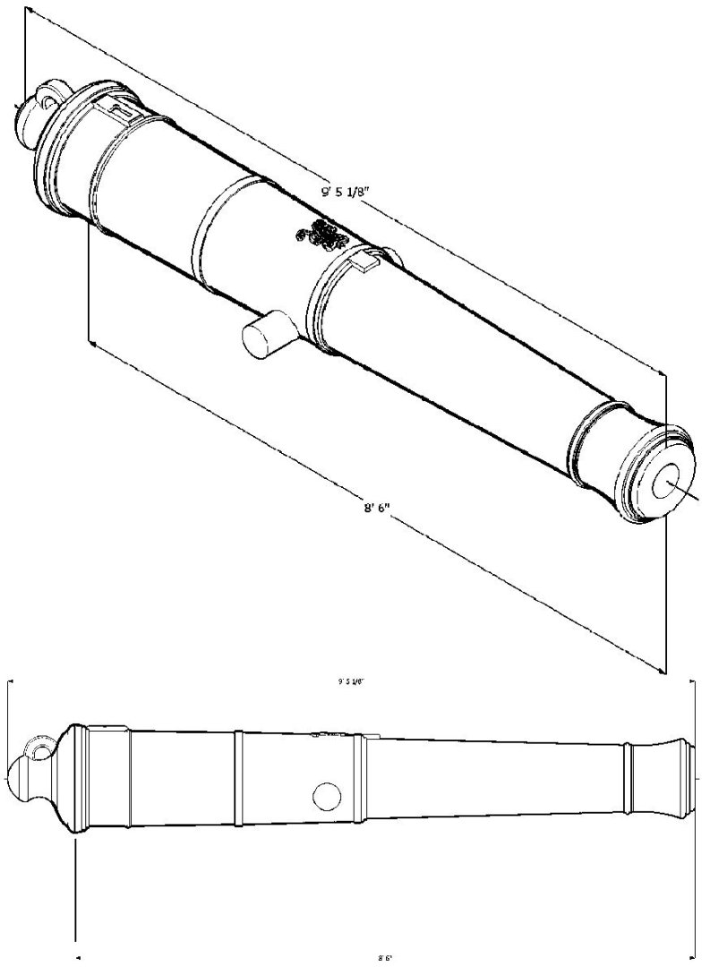
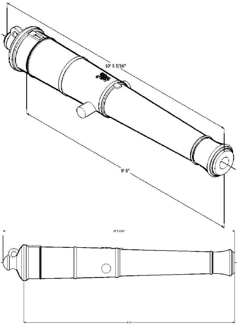
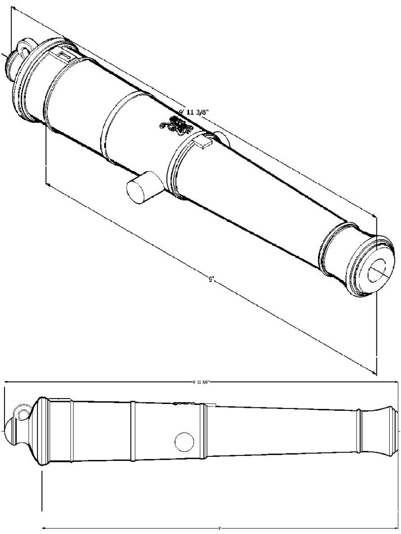
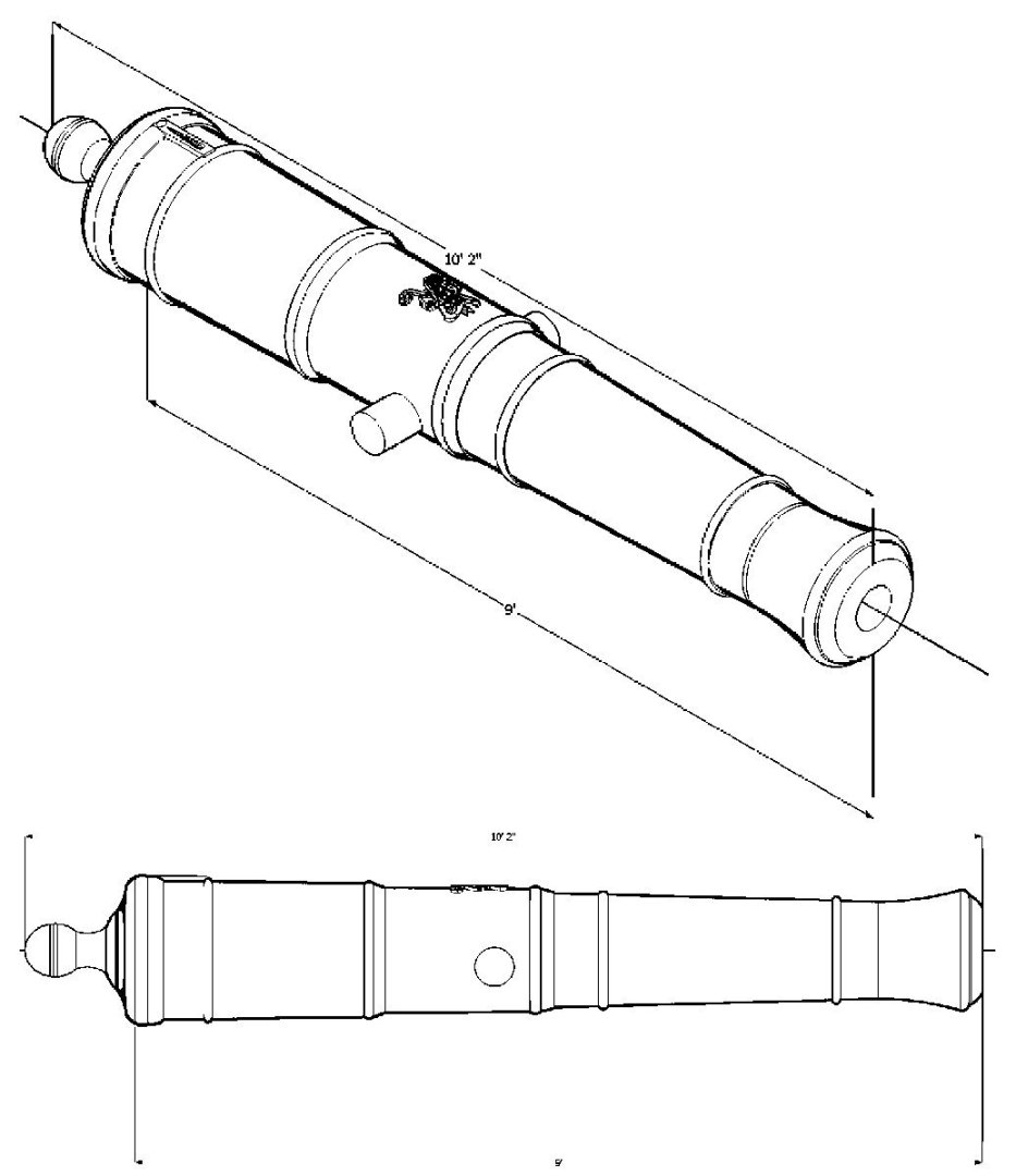
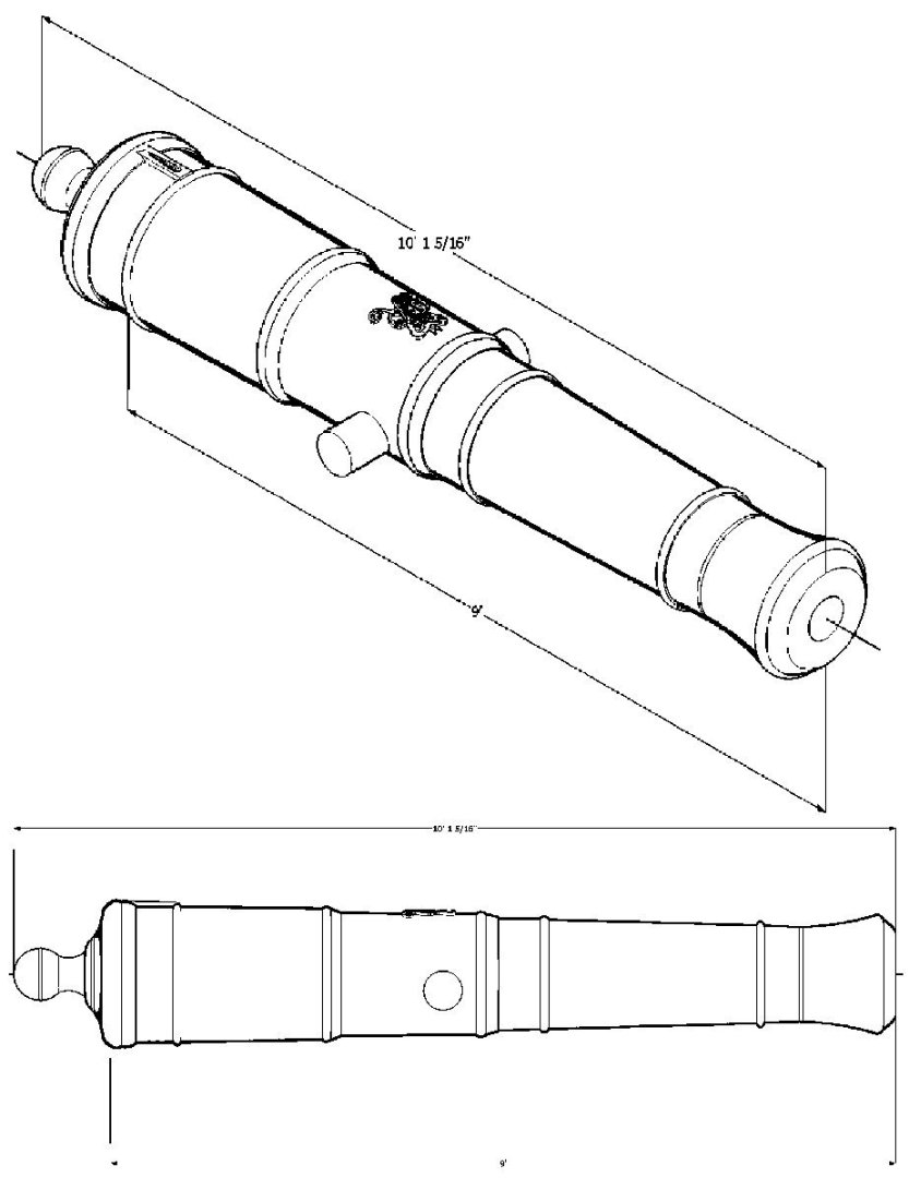
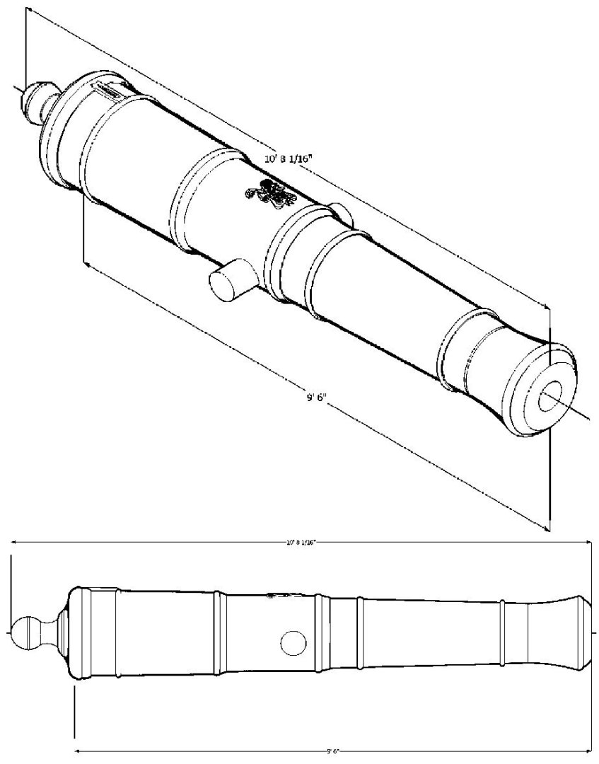
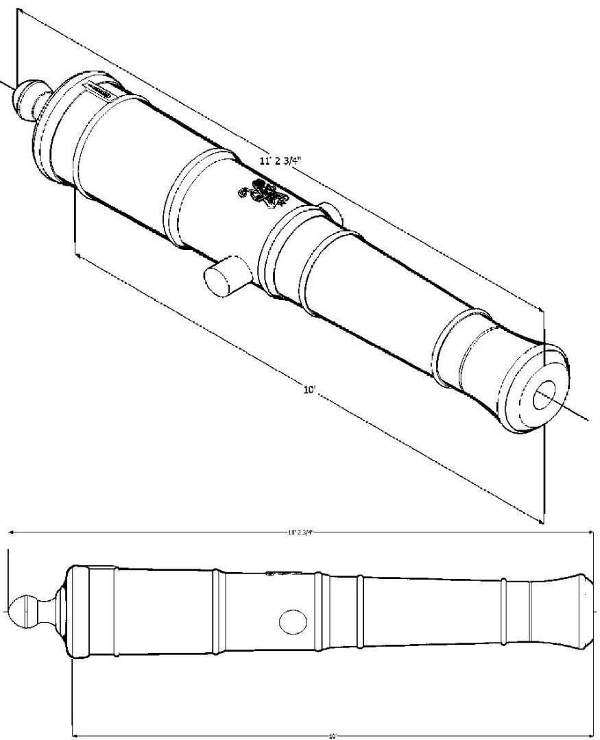
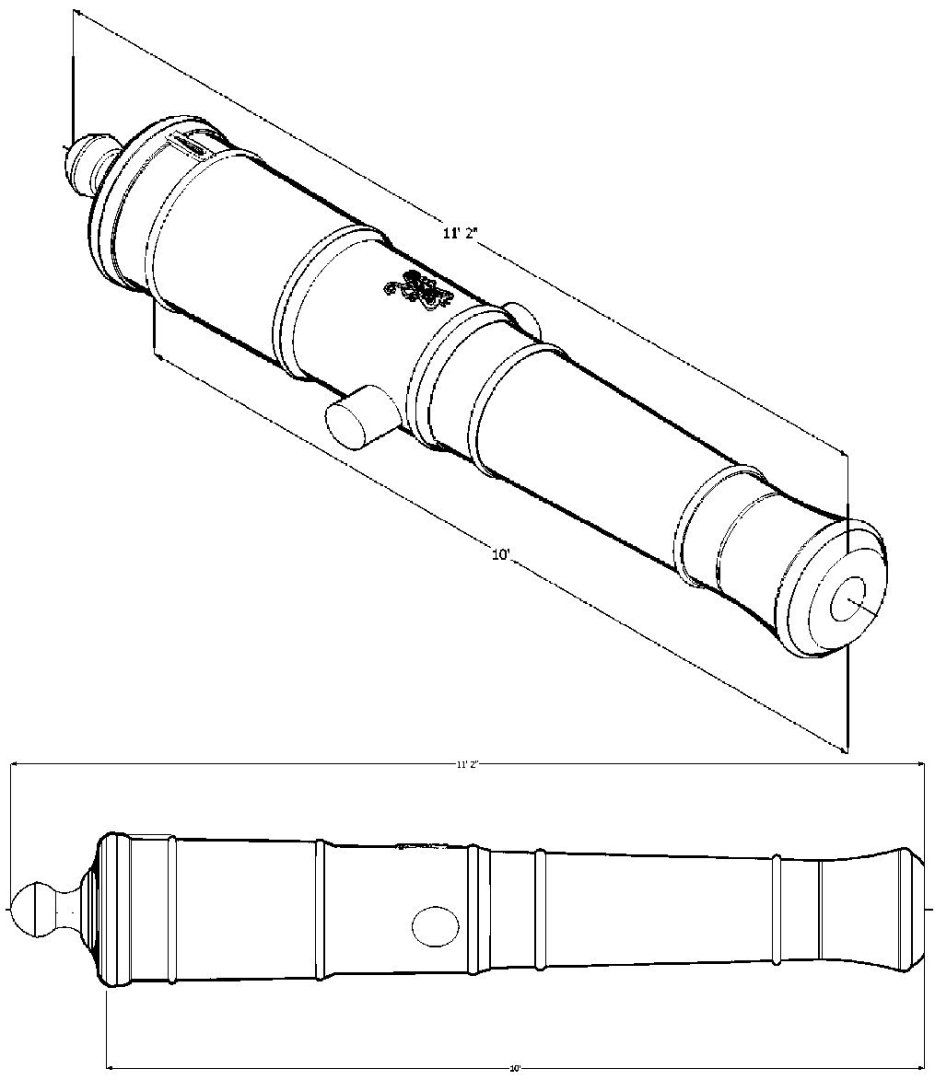
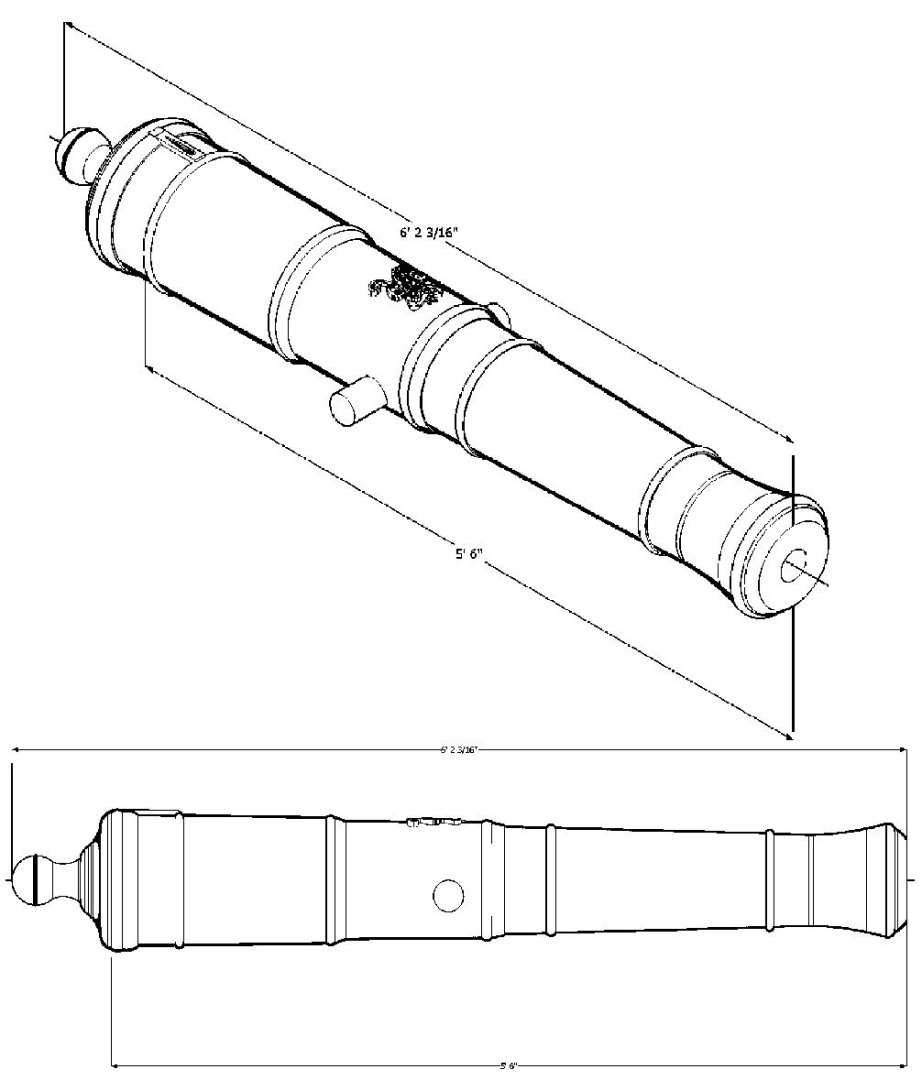
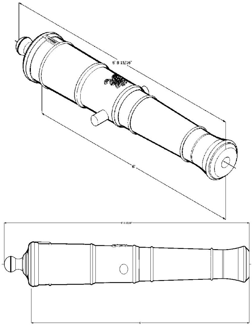
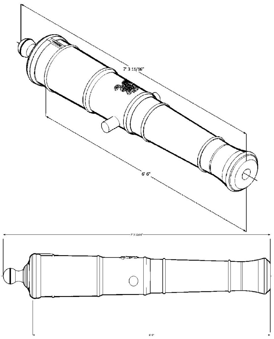
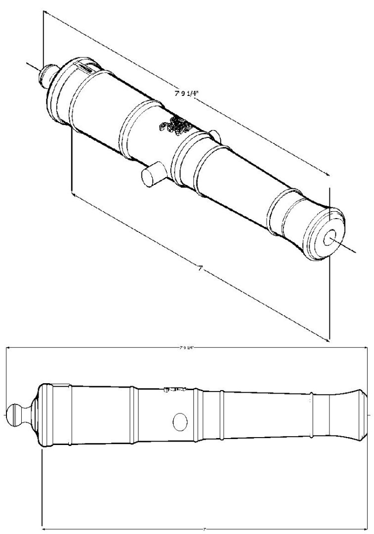
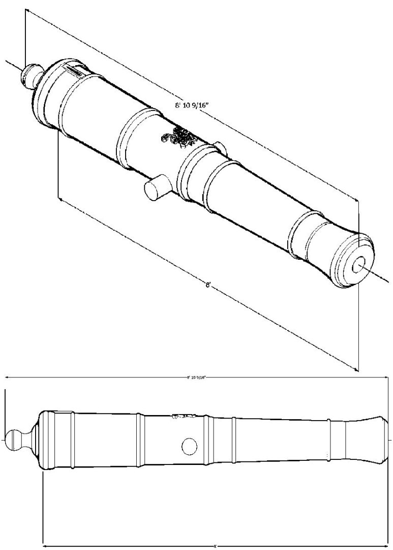
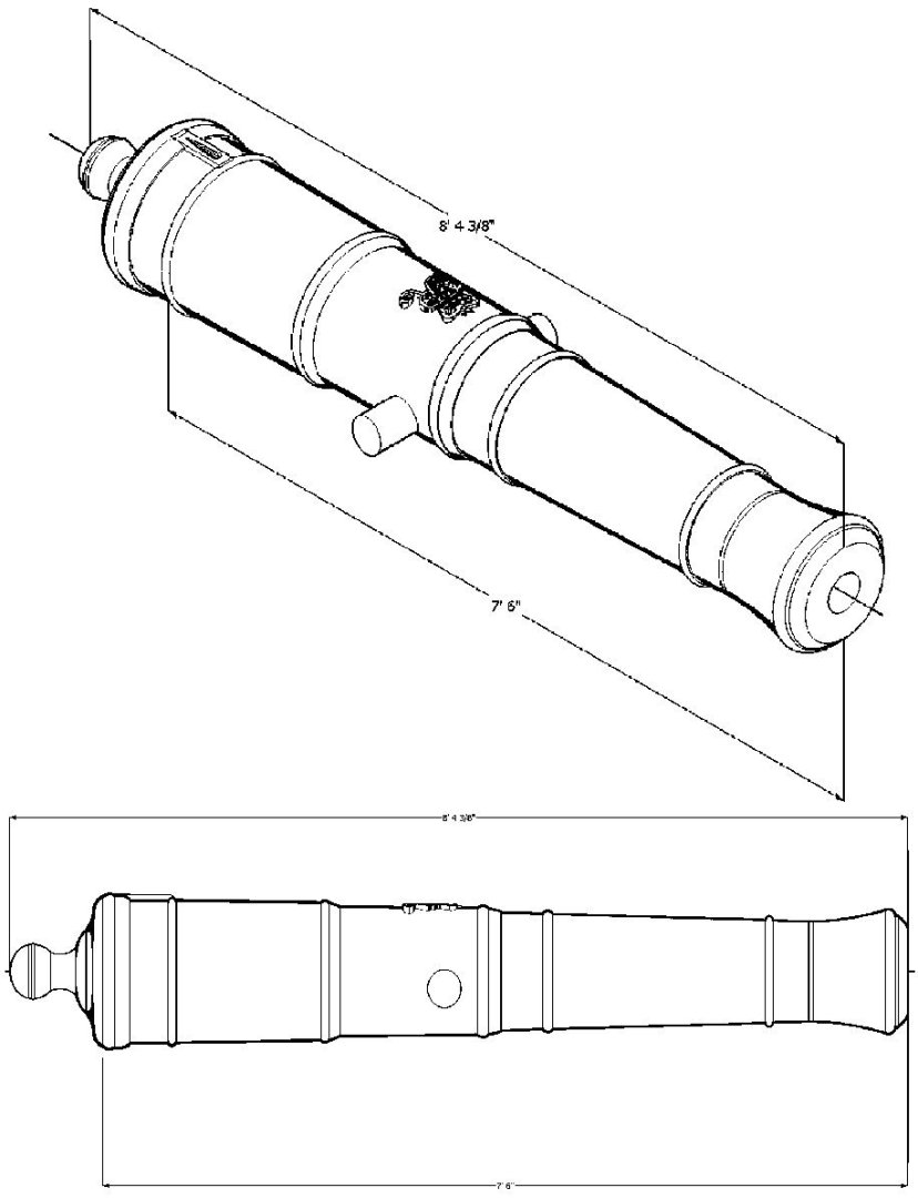
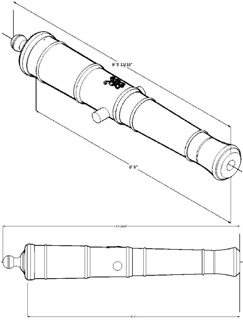
Armstrong Cannon Graphics - Part 1. I added the barrel lengths to the graphics, and converted them the black and white, so the dimensions showed better. 3 Pounder 54 4 Pounder 60 4 Pounder 72 6 Pounder 72 6 Pounder 78 6 Pounder 84 6 Pounder 90 6 Pounder 96 6 Pounder 102 9 Pounder 84 9 Pounder 90 9 Pounder 102 9 Pounder 108 12 Pounder 90 12 Pounder 102 12 Pounder 108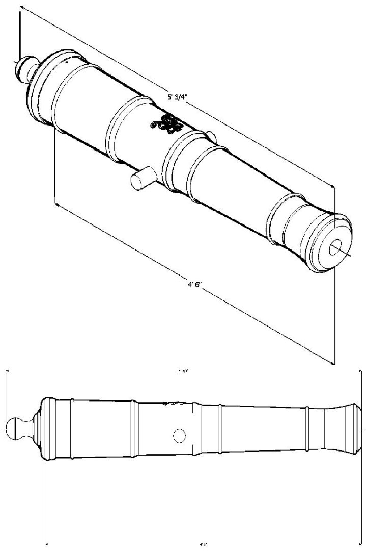


-
3D Printing Cannons in Resin
thibaultron replied to thibaultron's topic in 3D-Printing and Laser-Cutting.
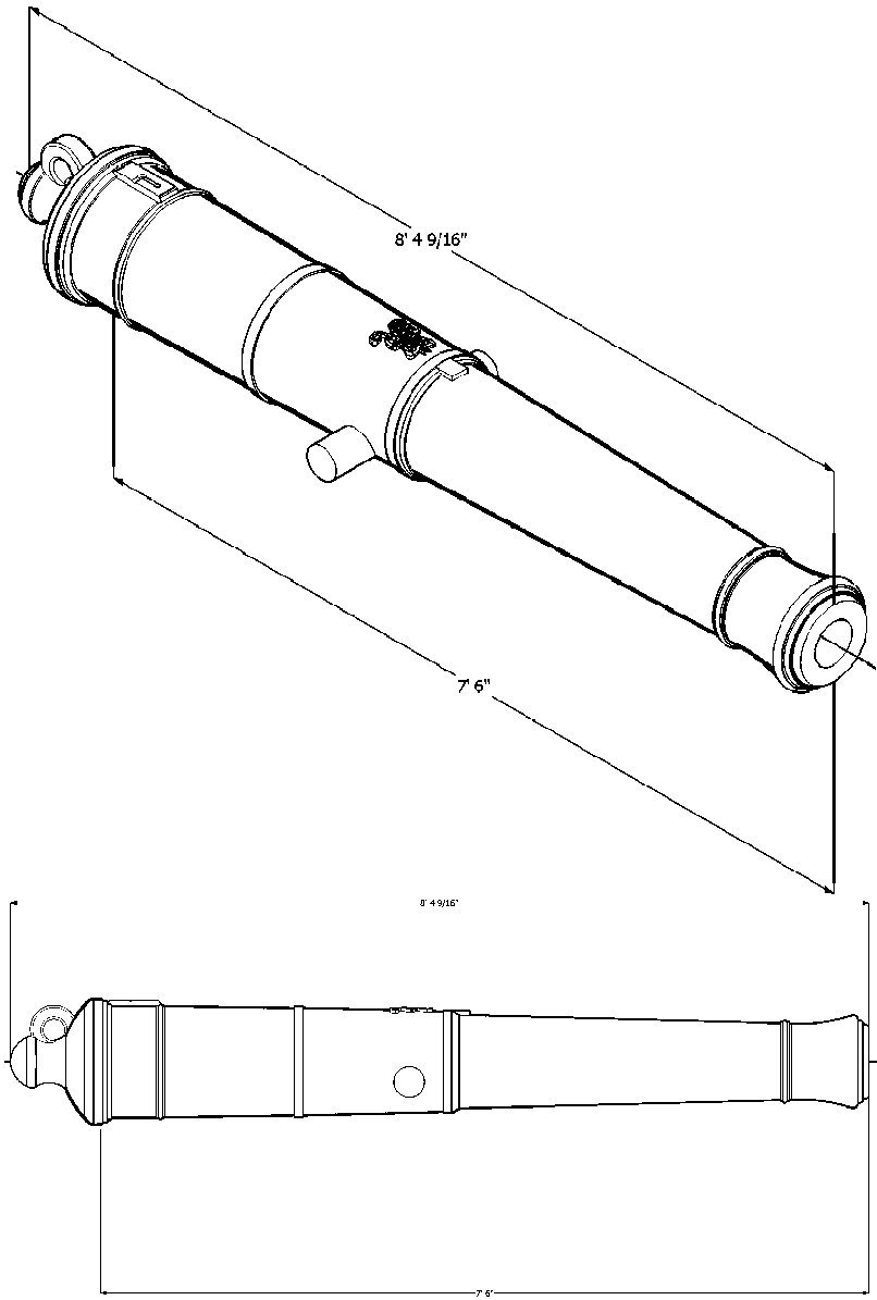
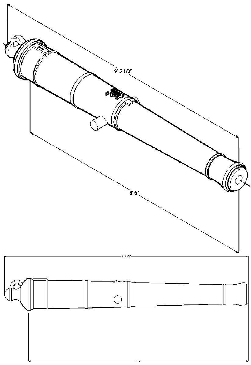
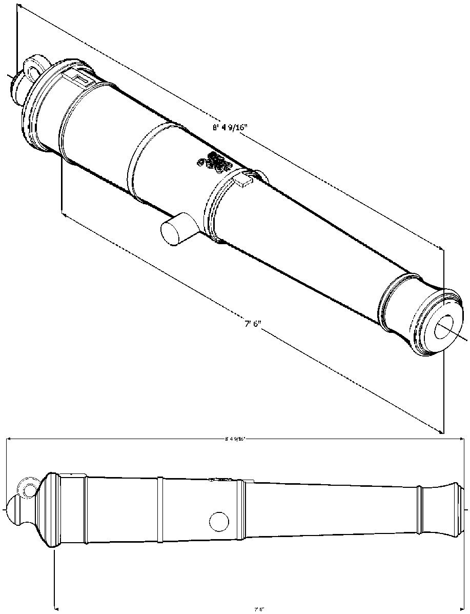
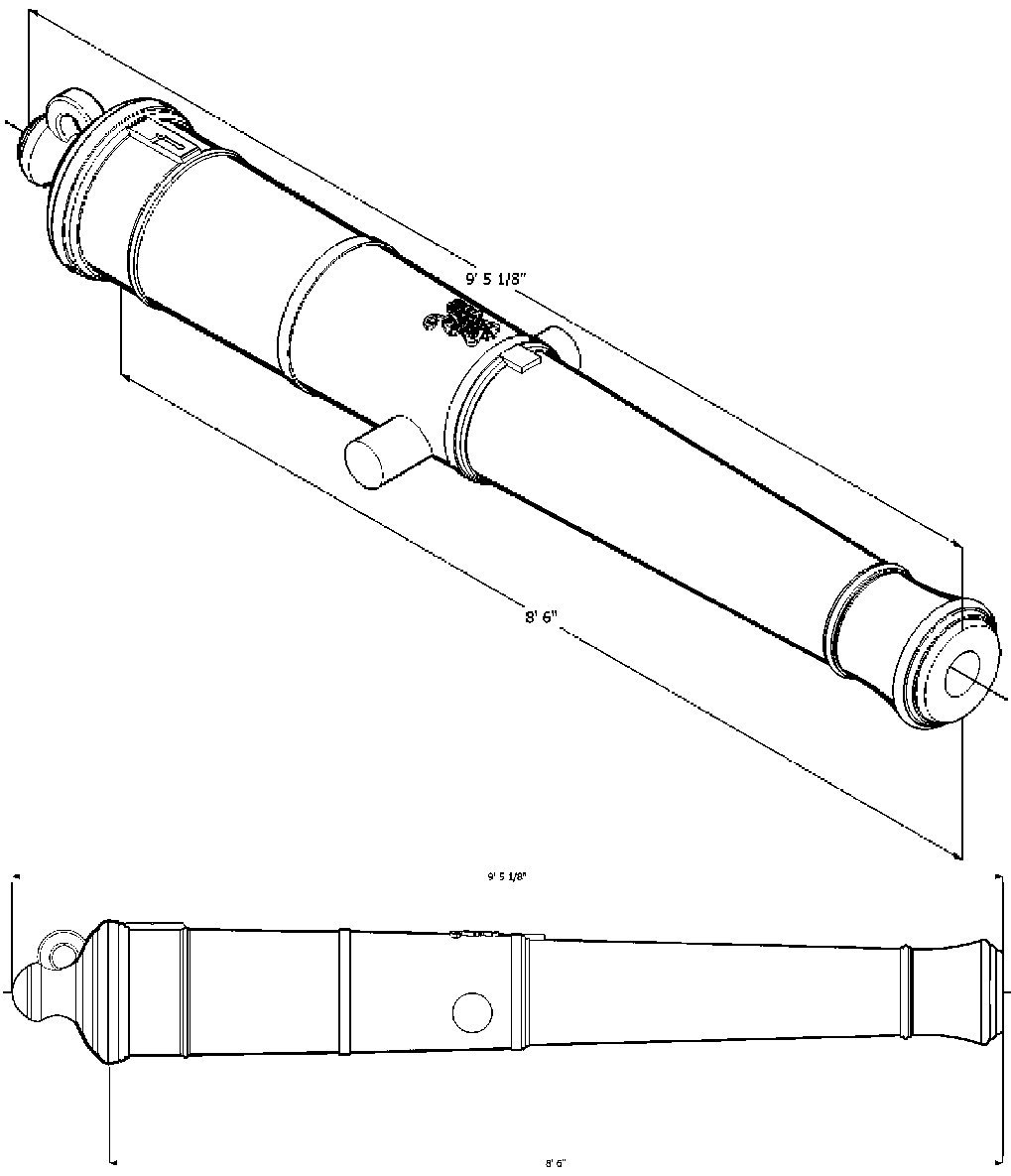
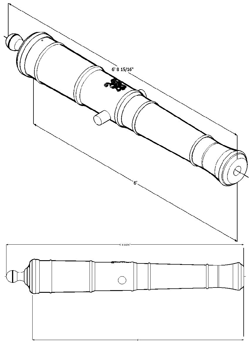
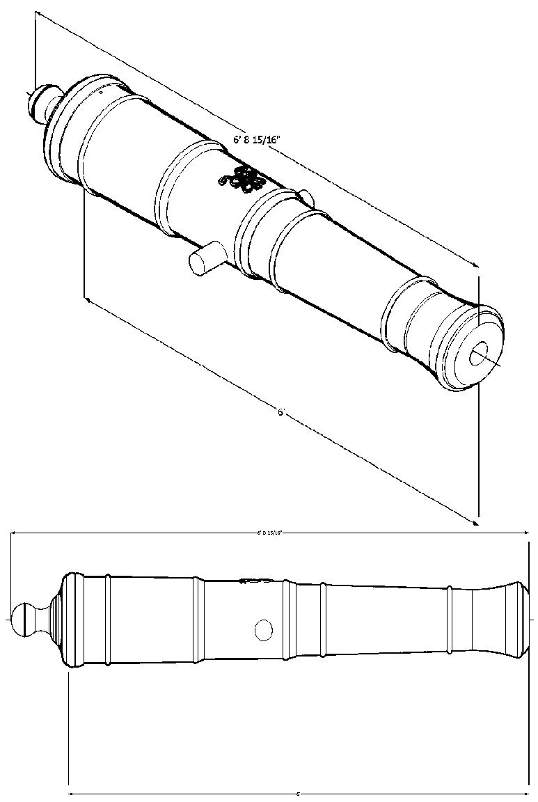
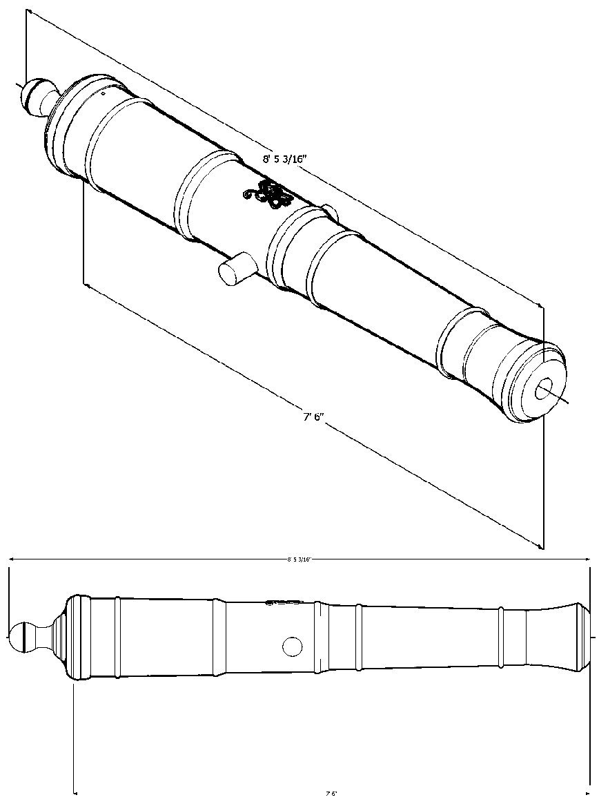
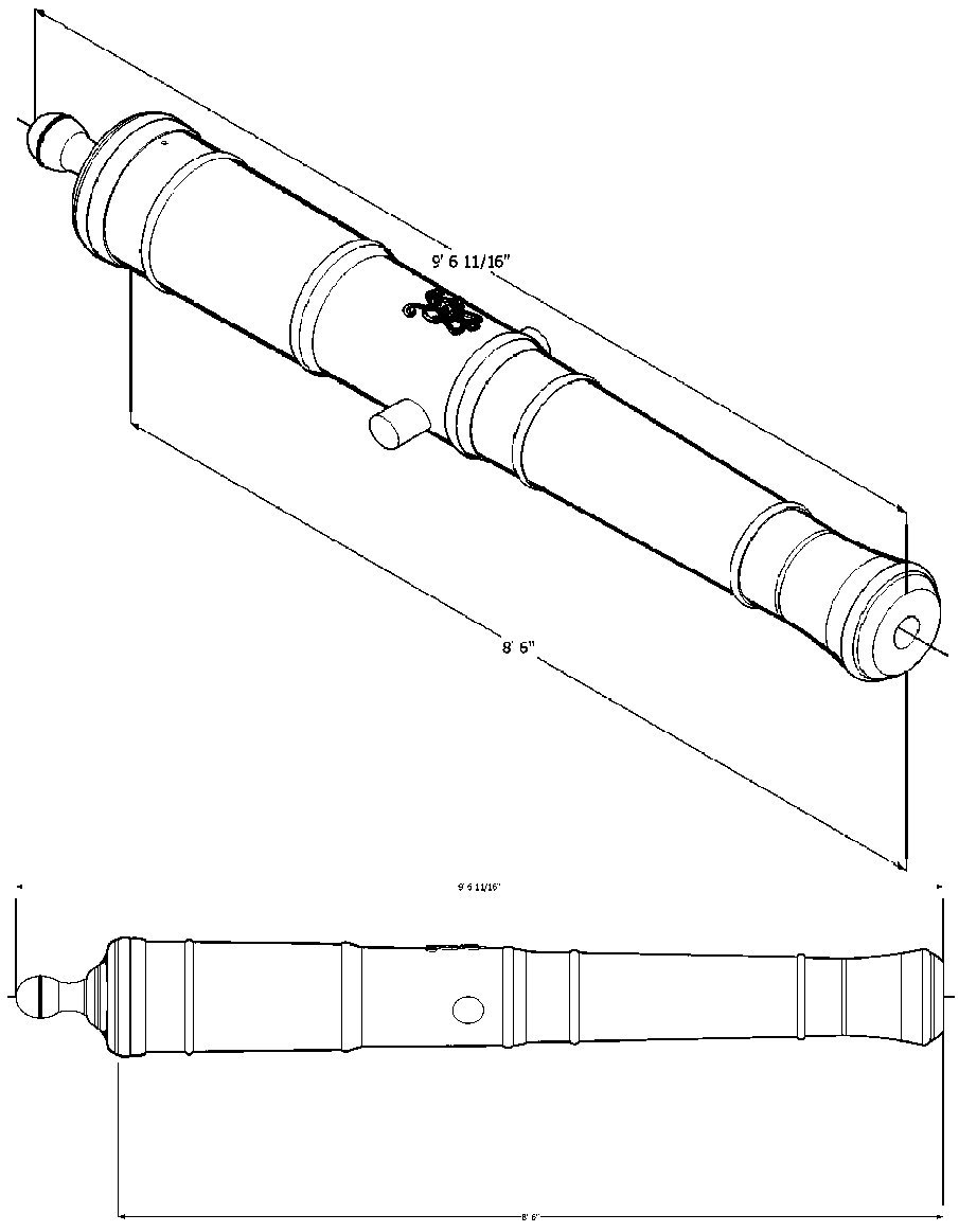
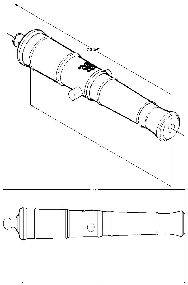
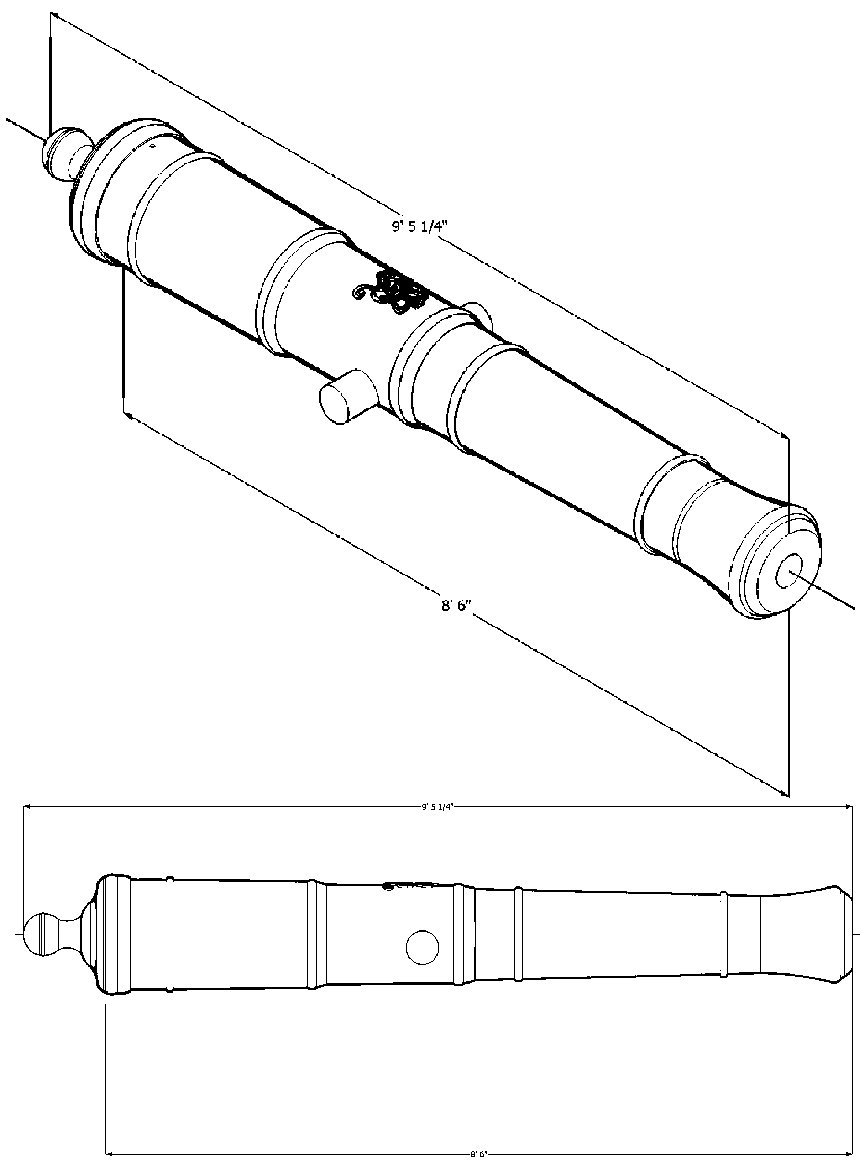
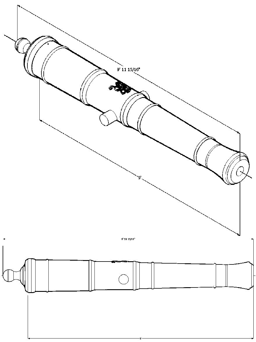
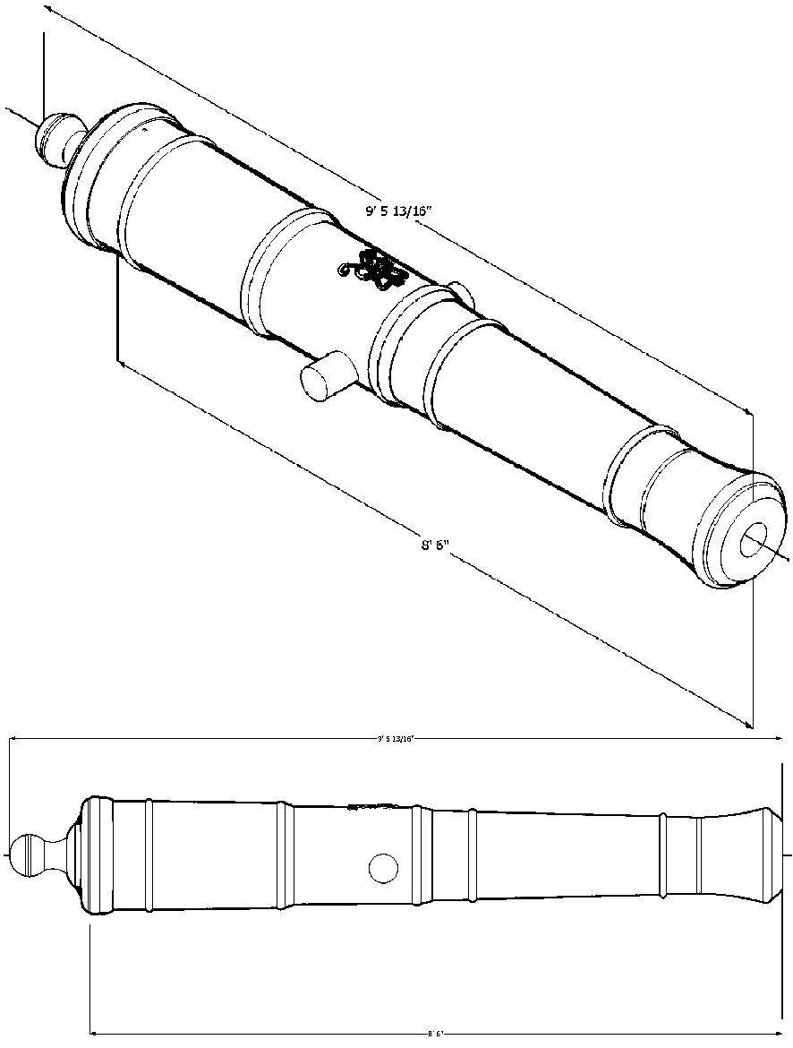
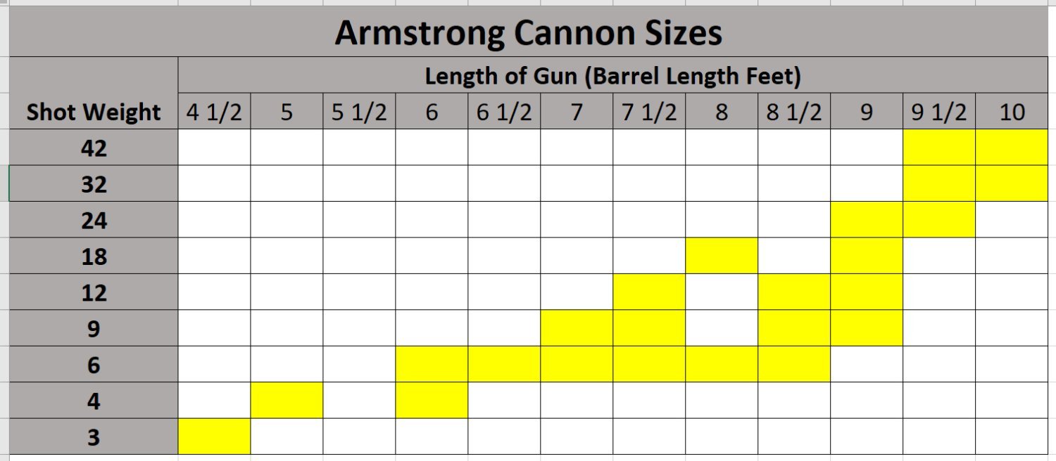
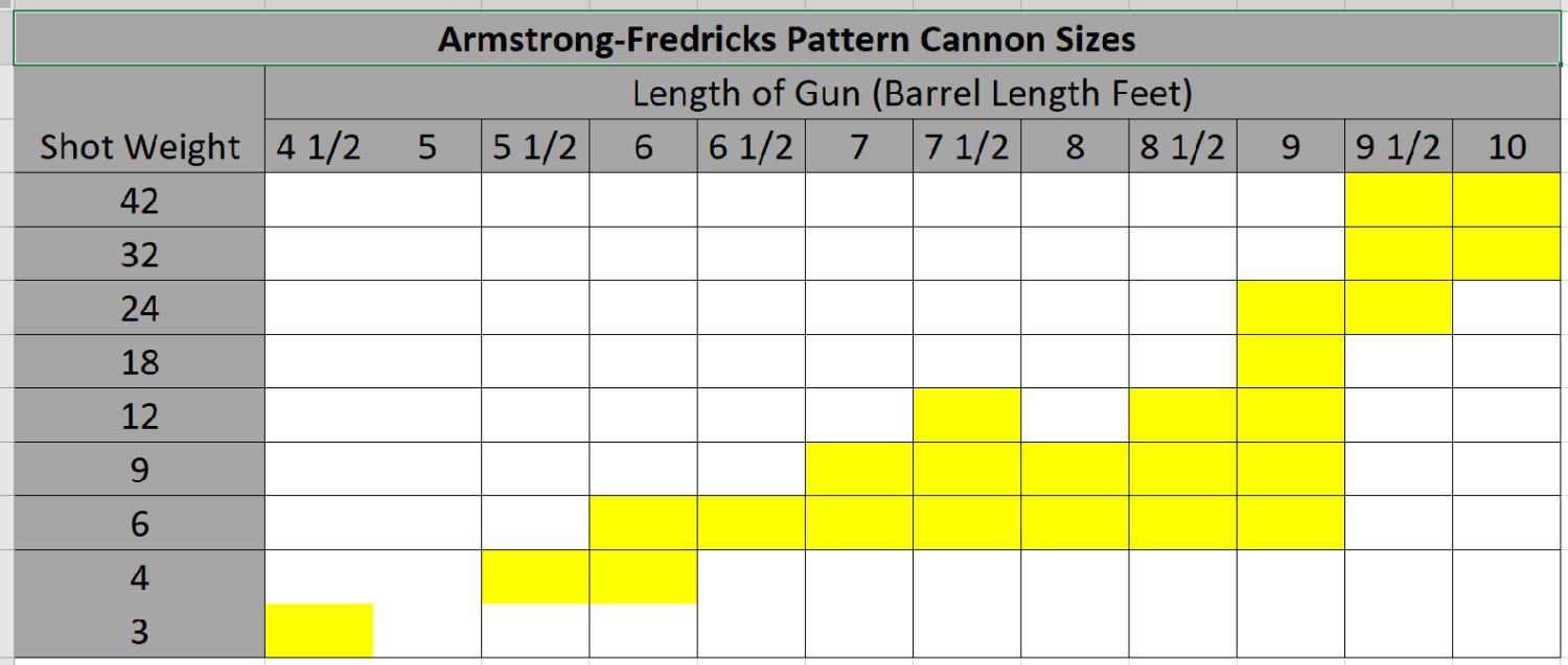
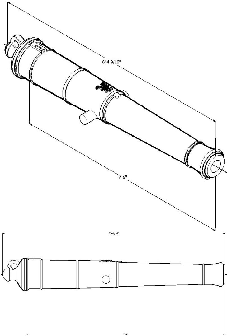
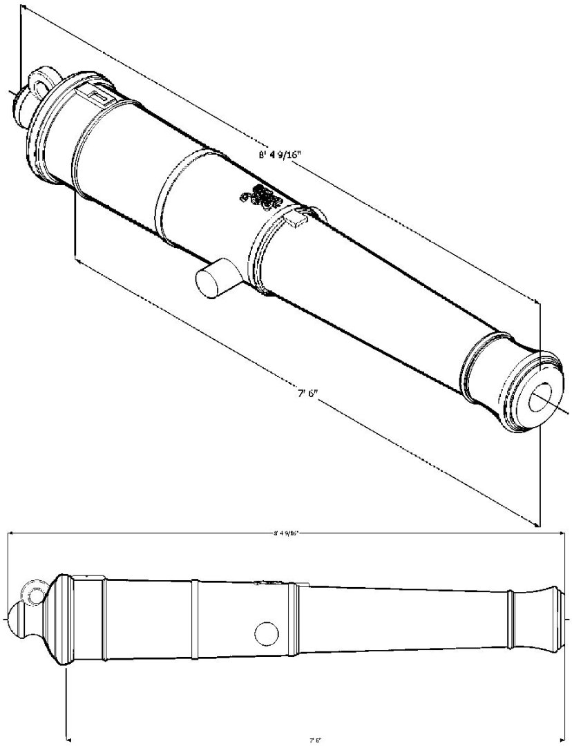
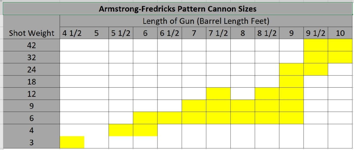
I've finished redrawing the Armstrong and Armstrong-Fredricks cannons, basing them on the breach diameter and length specifications at the Web Site: https://www.arc.id.au/ArmstrongPattern.html I used my existing drawings and scaled them accordingly. This is the last round, and I drew all the sizes shown in the chart for the Fredricks, and the sizes of Armstrongs listed by Lieste in a previous post. Below are the two charts, the graphics and STL files will follow in subsequent posts.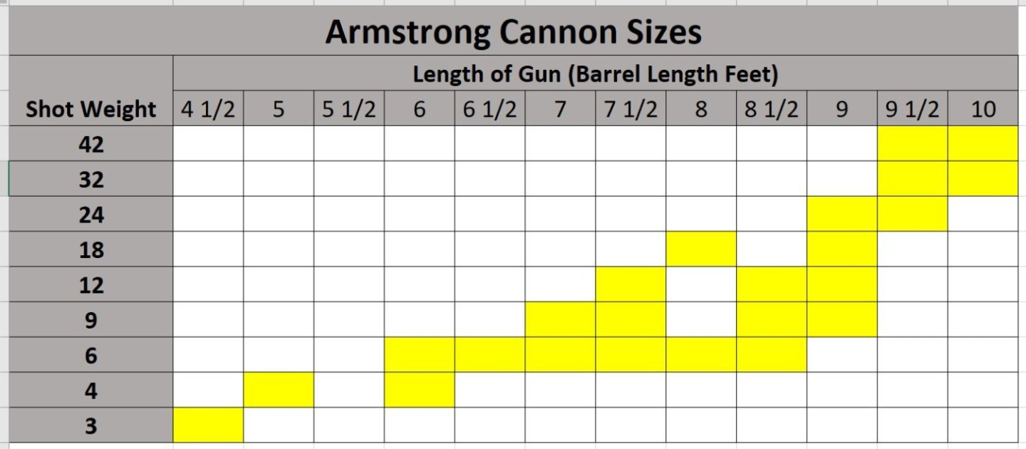
-
About 2 foot. With age a small ship at a larger scale is appreciated.
-
How about a Sharpie, They were endemic along the east coast, with several styles to choose from. Each area had their own version.
-
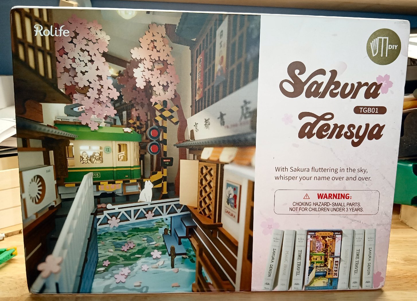
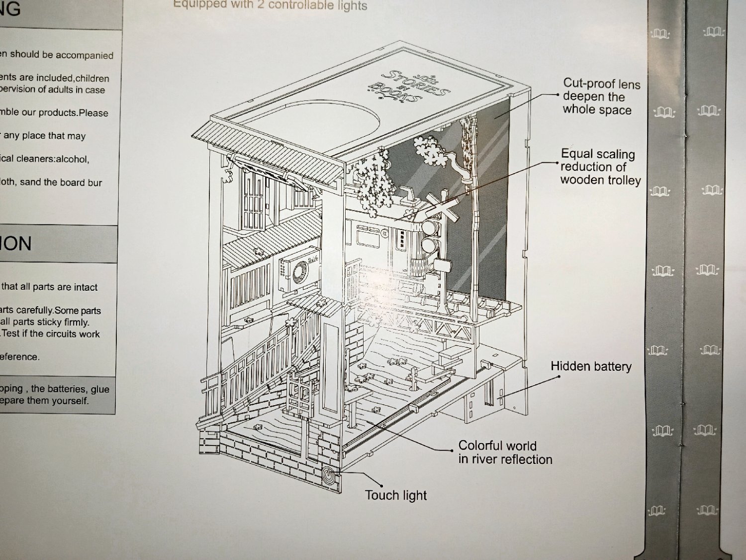
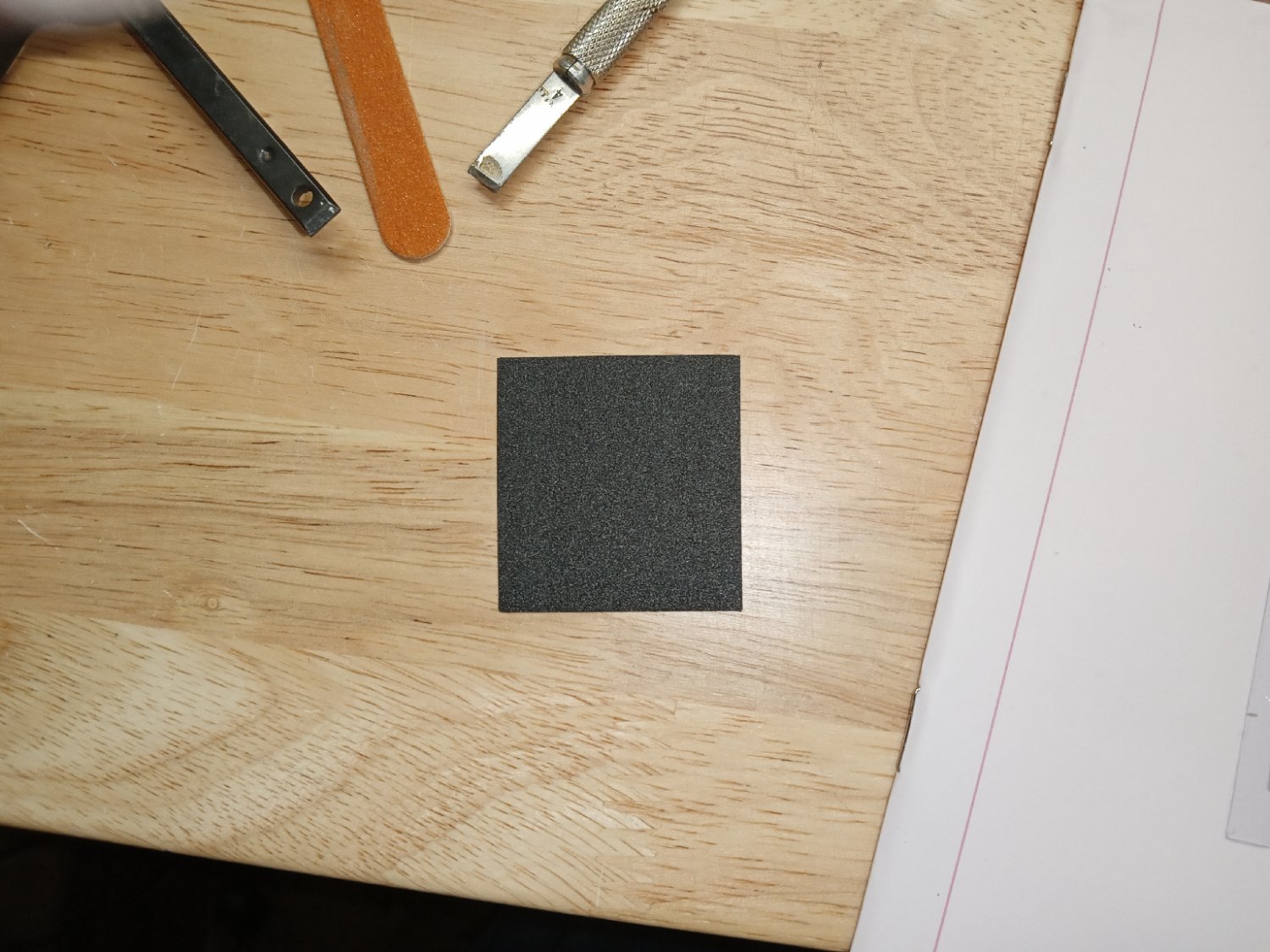
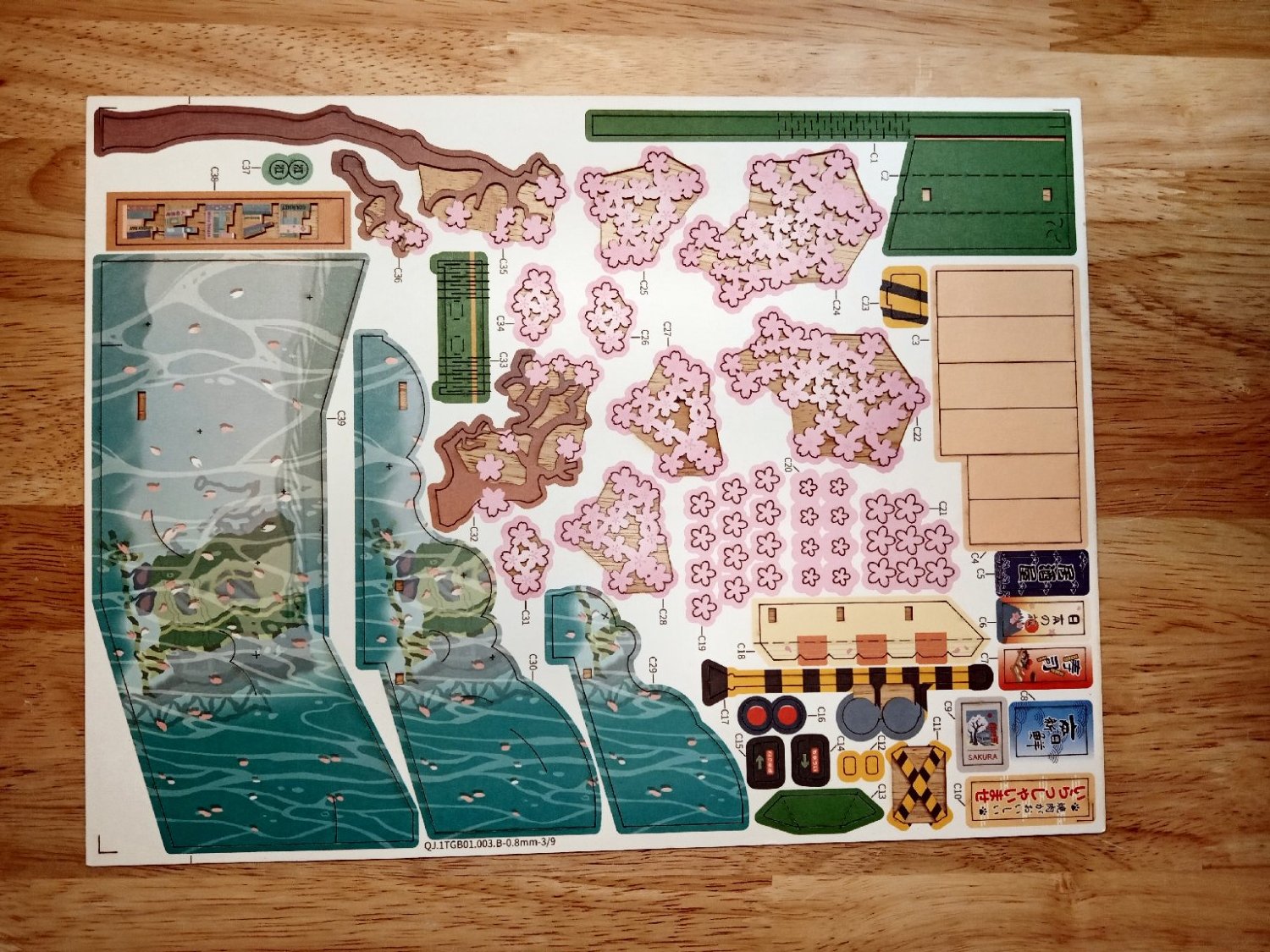
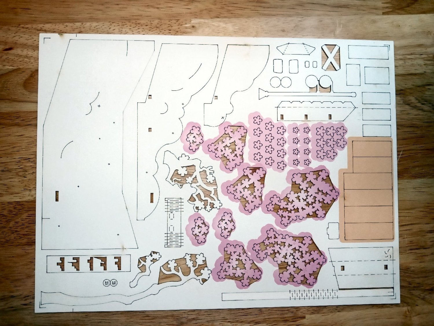
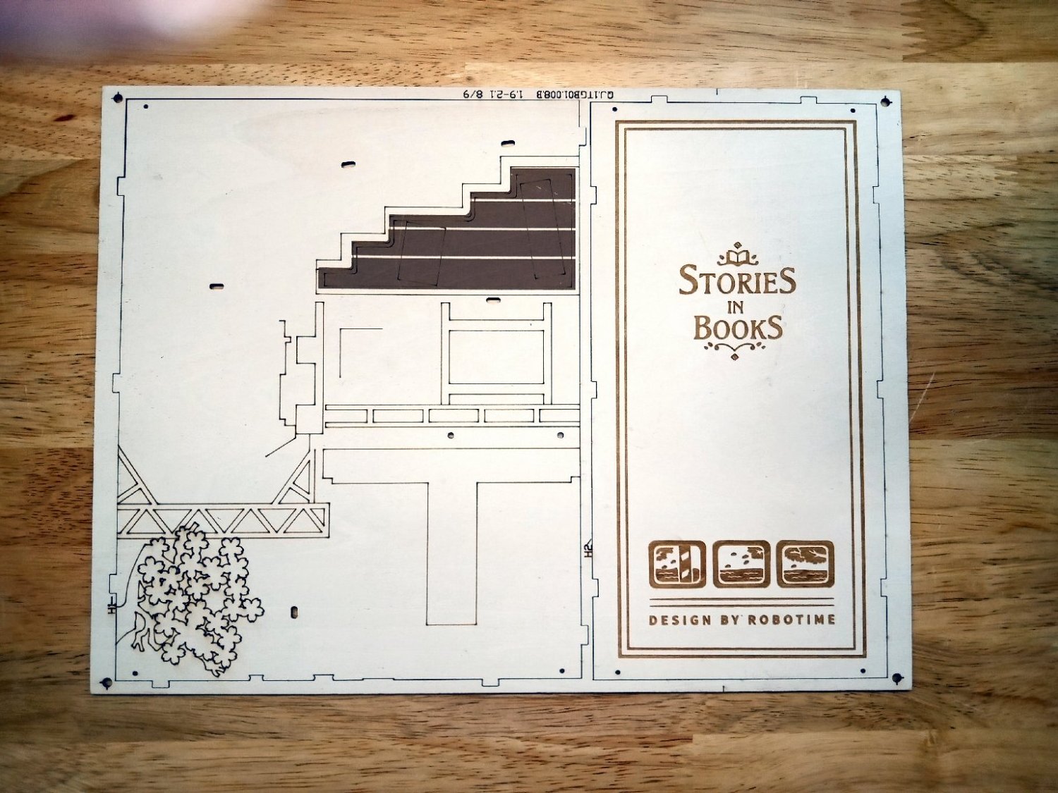
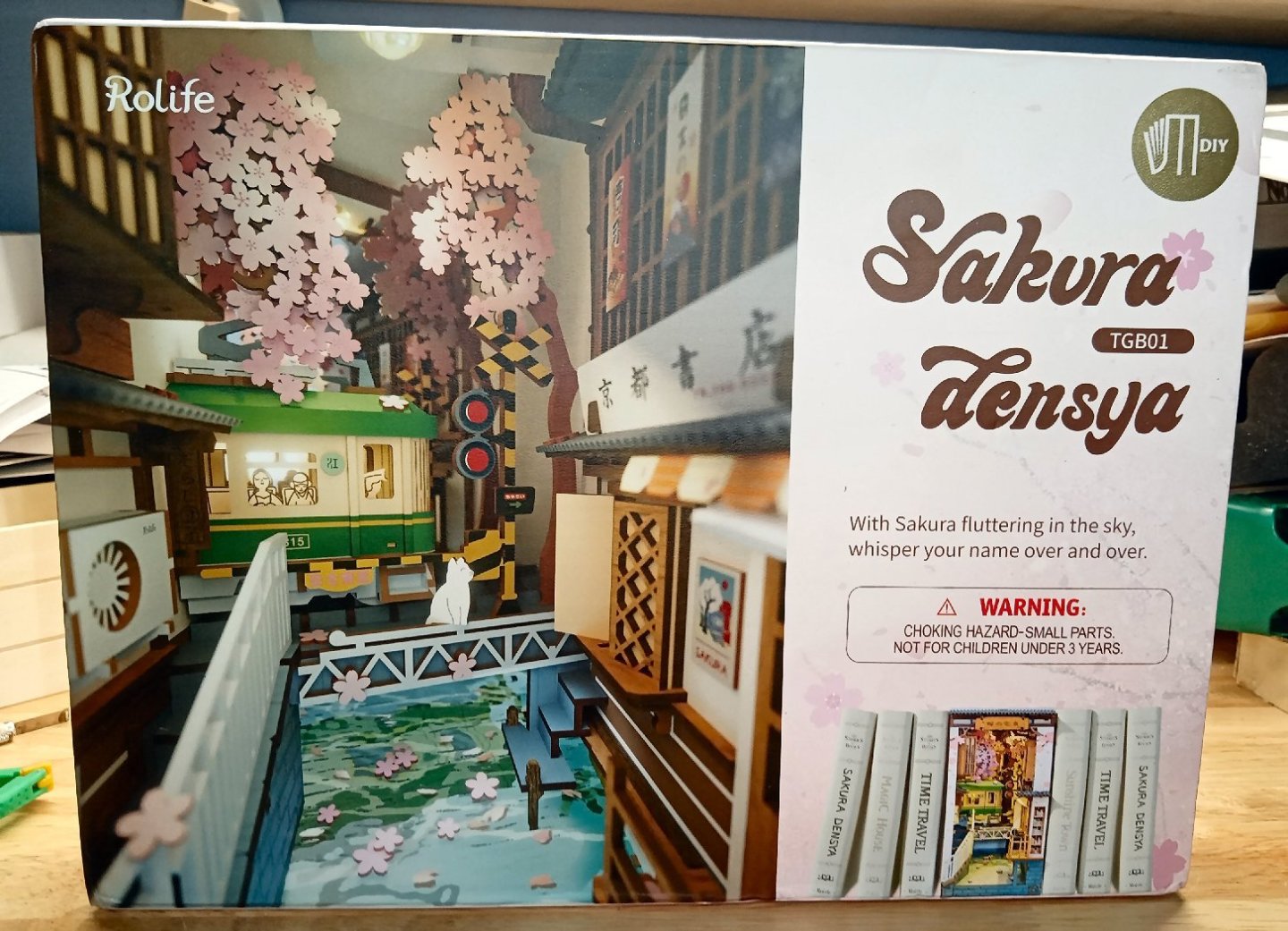
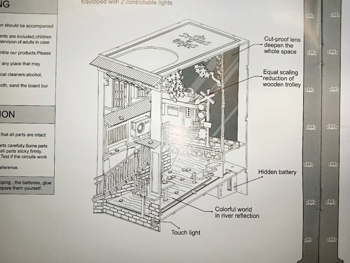
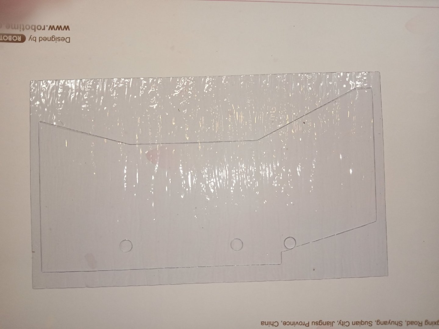
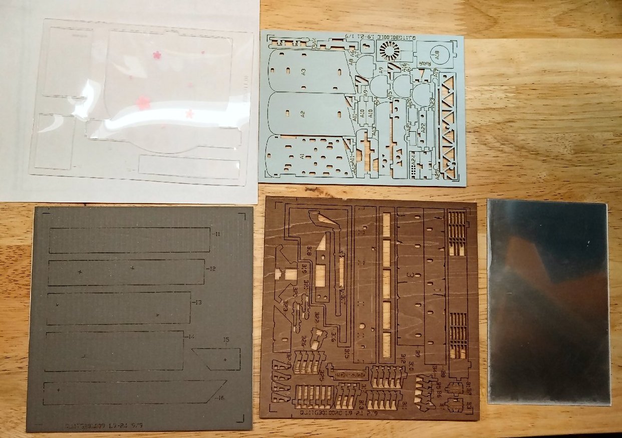
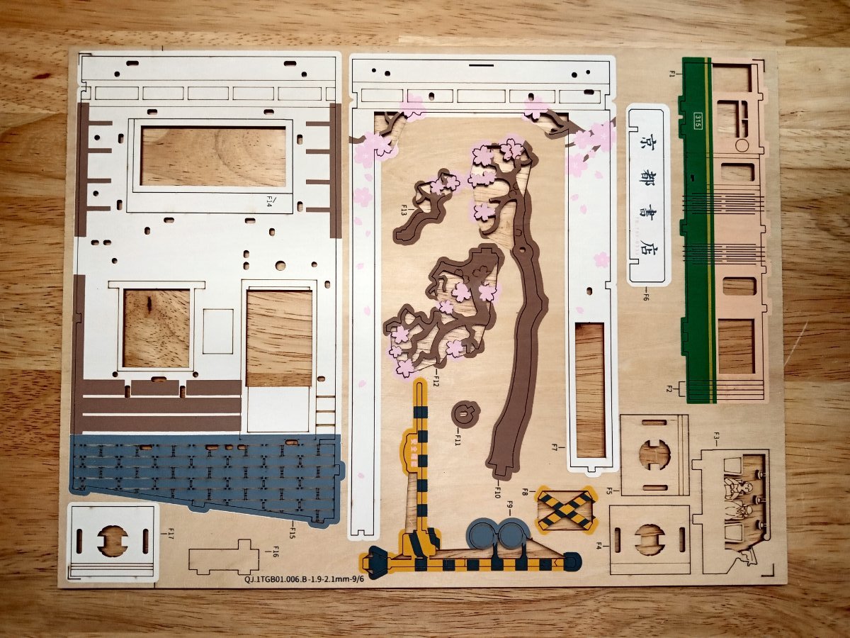
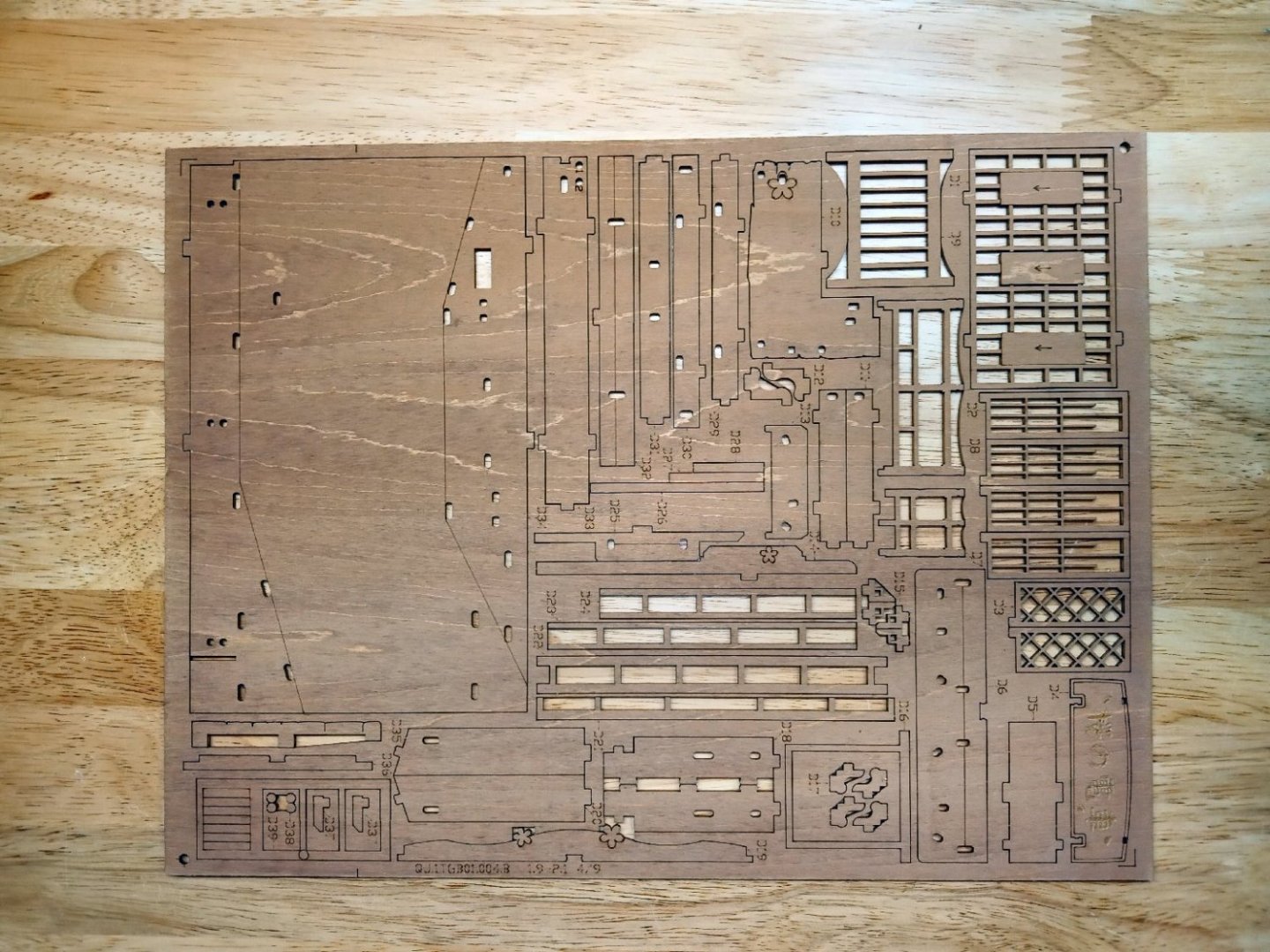
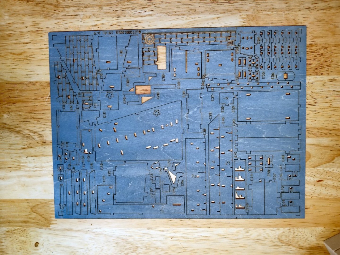
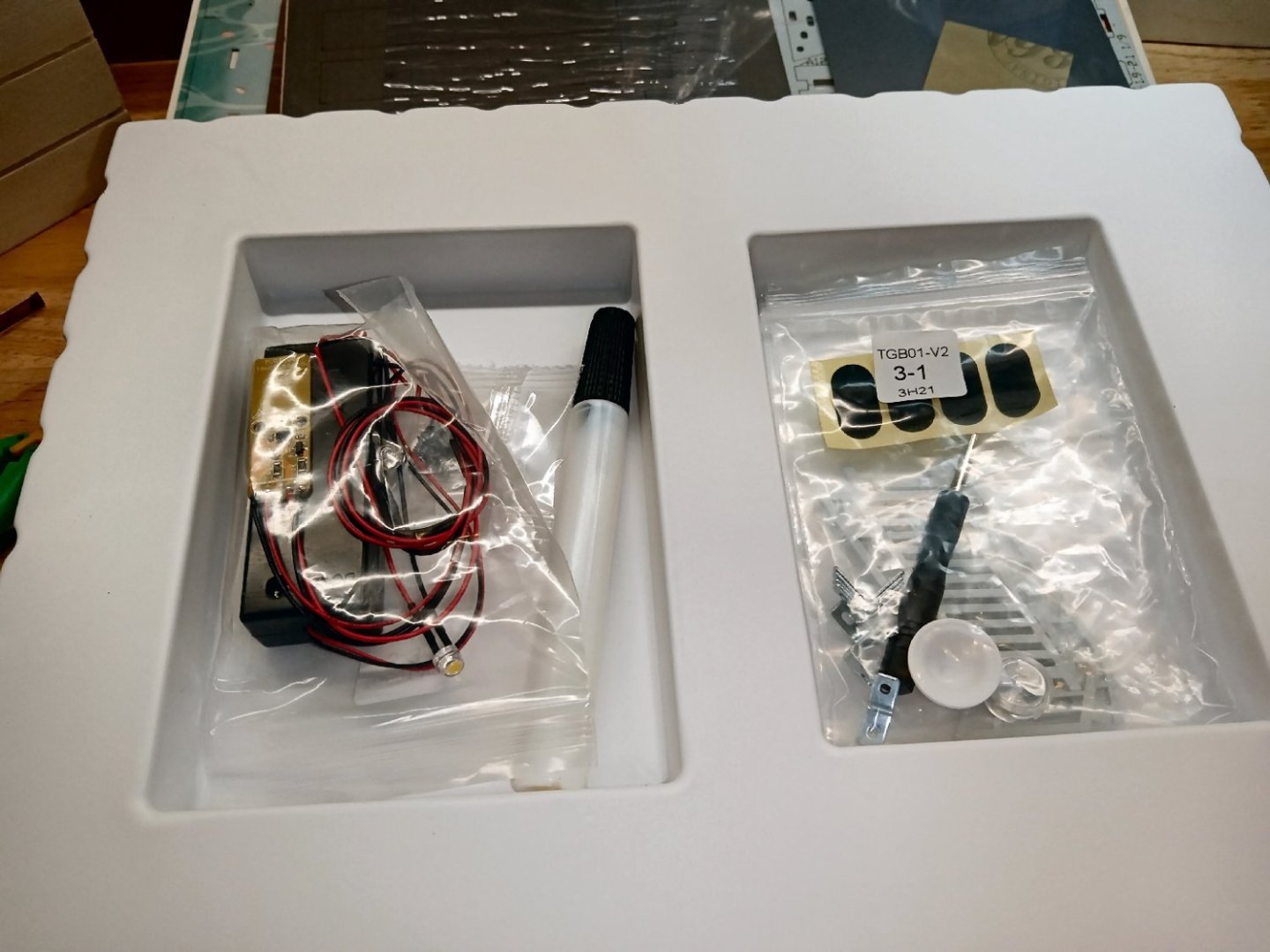
Part_001 I decided to build the companion diorama to the previous “Sakura Travel” Book Nook book sized one. “Sakura Travel” depicted a tram coming out of the diorama, this one shows a similar tram crossing a street at the back of the scene. I would rate this one as a medium skill kit, for one listed as for age 14 and above. There are the structures along the street, the two-layer pond, etc. enough detail to rate a 33-page instruction manual, rather than the two sheets of small poorly printed instruction sheets the previous kit had. Some the high skill level ones are the equivalent of a complex Card Airplane kit, with lots of printed sheets where you must cut the details out. I have one which is a library where you need to cut out the book covers. This kit has a rear mirror to add depth to the scene. The finished diorama has some exterior structures at the front. Two structures are sections of roof overhang, and the two are a porch with a railing and the end of the stairway, with railing. The top features a clear “window” allowing for better overhead room lighting. The river/pond has a colored bed with a clear rippled plastic water surface, raised slightly, to show some depth to the “water”. This shows the back of the box, with a drawing of the interior of the kit. Sorry for the one glare spot. This kit has a recessed area at the bottom, rather than a solid piece. The overhead window is the arch shaped area at the front of the top, glazing is provided for this area. The kit has all the plywood and cardstock pieces shrink-wrapped together. This is the rippled water surface. The three holes are for piers that support one of the structures. They even supply a small (about an inch and a half square) piece of sandpaper to smooth rough edges. Here are a couple of shots of the instruction book. This shows the mirror, a sheet of wooden railings, and window frames (etc.), textured (though you can’t tell in this photo) roofing, a sheet of painted wooden parts, and the clear glazing for the window in the top of the case. This sheet is laser cut cardstock, with printing on both sides, where the parts are double sided. The individual blossoms are glued a various location to represent fallen blossoms. Next is a plywood sheet of parts, again, painted on both sides where needed. My only real beef with this kit, is that unlike the "Sakura Travels", the people in the tram are not painted. I'll have to fix that, so the two match in appearance. Here is another sheet of wood parts. These sheets are the book cover/case parts. This sheet has various masonry and other blue parts The last photo is the parts tray. The parts are the LED light harness, a glue tube with a fine tip, fabric feet, some additional railings, and a handful of angle brackets, used to reinforce the case. One disappointment to me is the fact that the two kits in this series use different voltages for the LEDS. This will complicate the building of a power supply to replace the battery packs in the number of kits I have.


- 25 replies
-
- 11
-
-
3D Printing Cannons in Resin
thibaultron replied to thibaultron's topic in 3D-Printing and Laser-Cutting.
Here is a chart of the Fredrick Cannons that will be available: The Orange blocks are cannons listed in the 1760 list, the Blue are those added in 1764, The Red are cannons that were shown in the drawing I used. This chart is from the Web Site I found. I will make a similar chart for the Armstrongs listed in an earlier posting in this thread. The Armstrongs will be the same cannon designs, but with a touch hole, rather than a flash pan.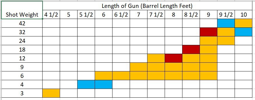
-
3D Printing Cannons in Resin
thibaultron replied to thibaultron's topic in 3D-Printing and Laser-Cutting.
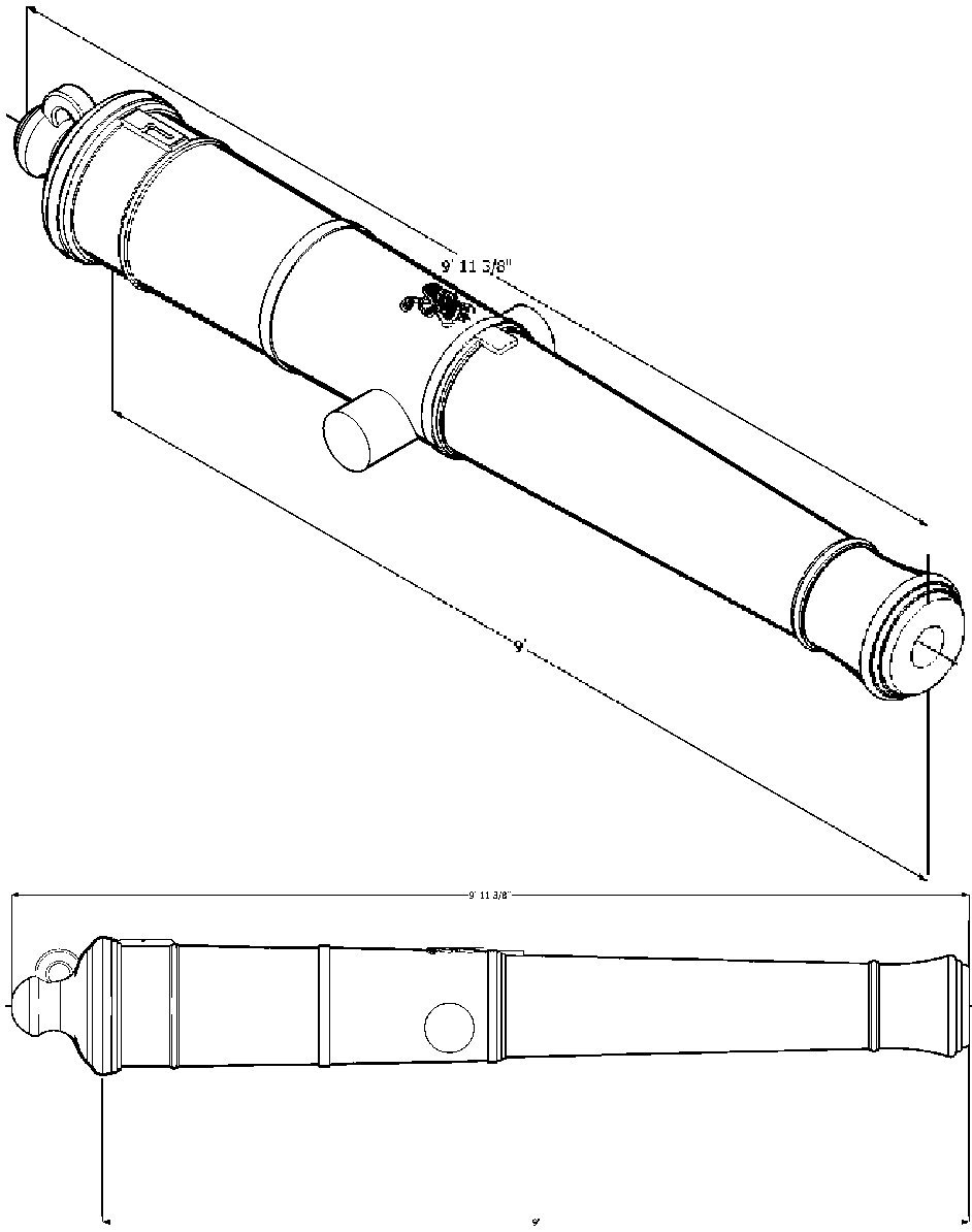
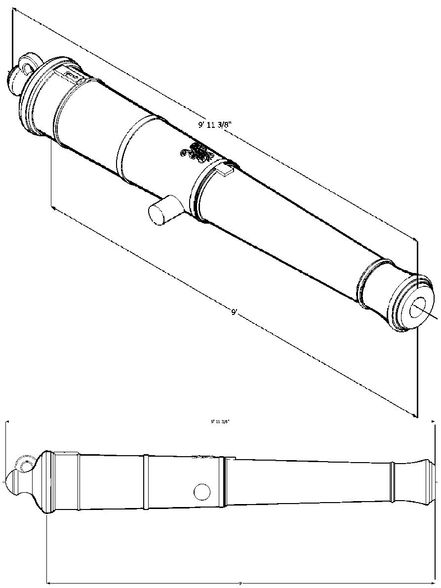
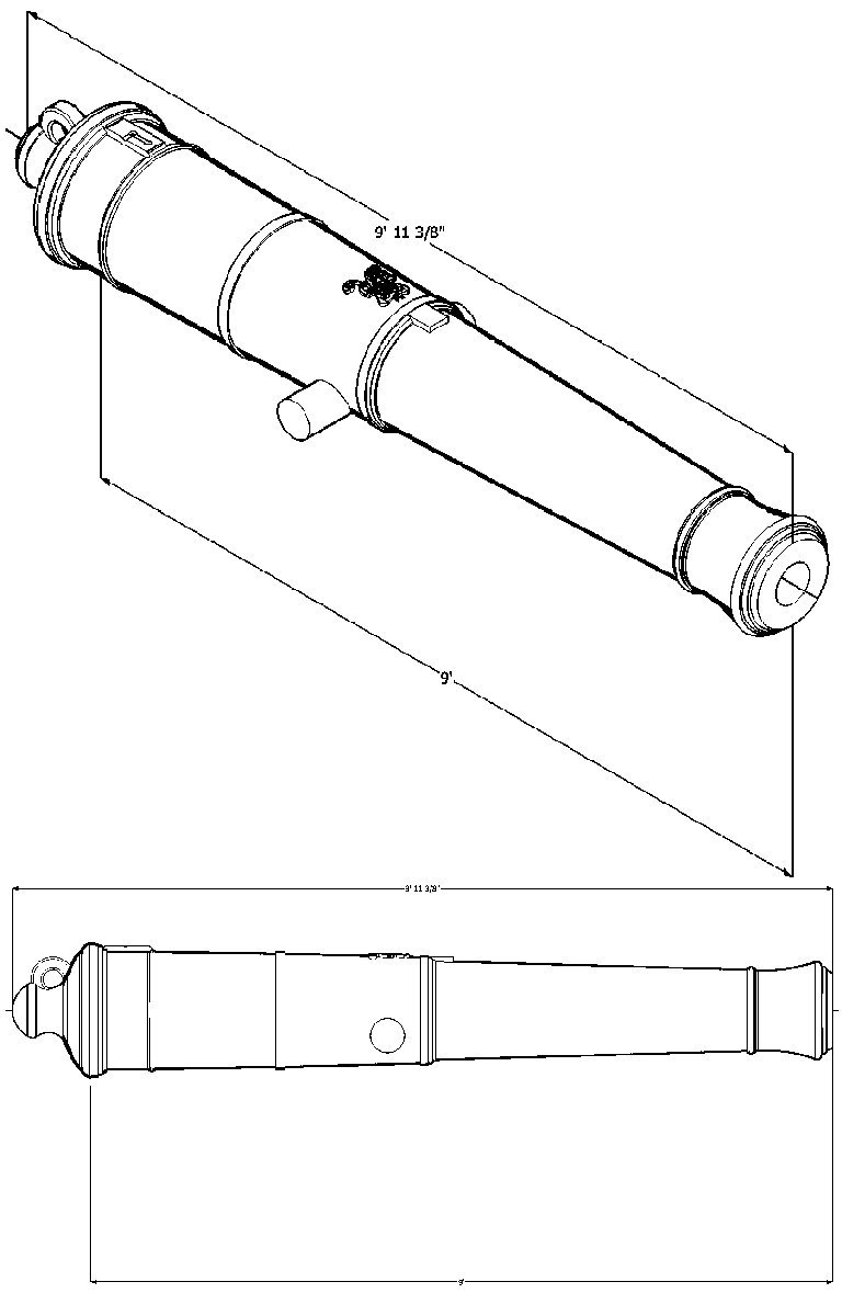
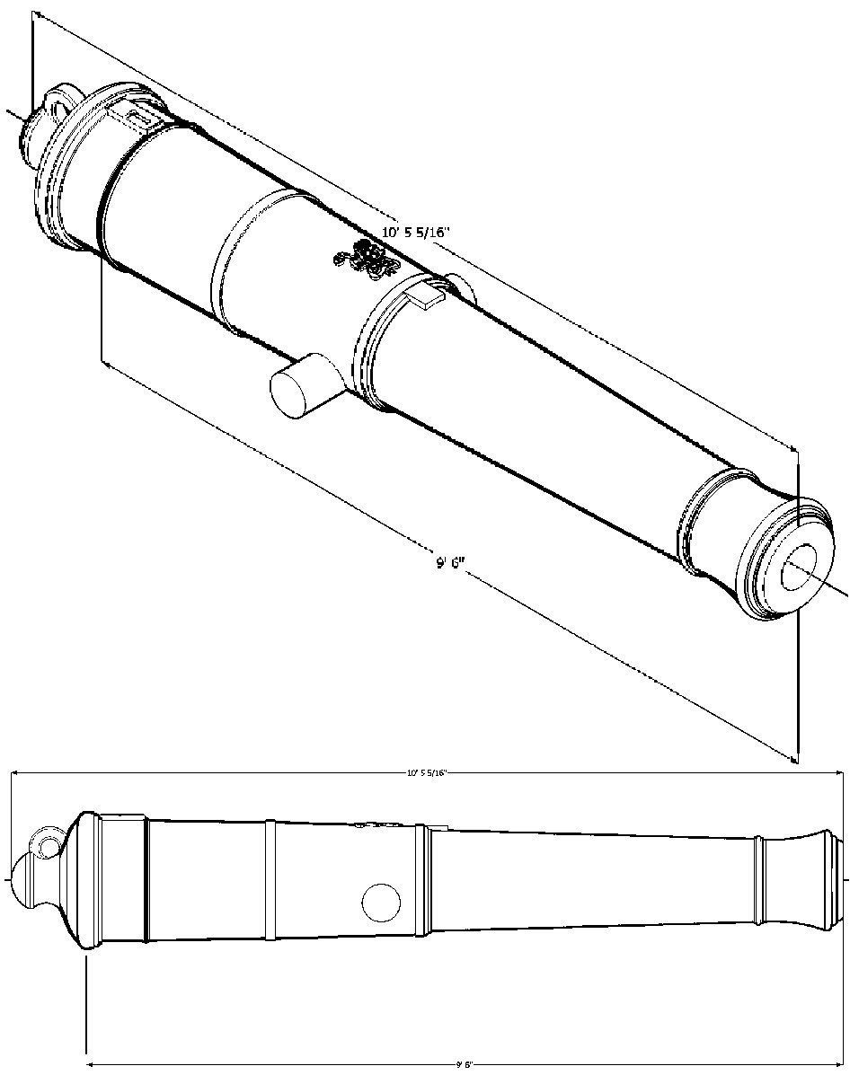
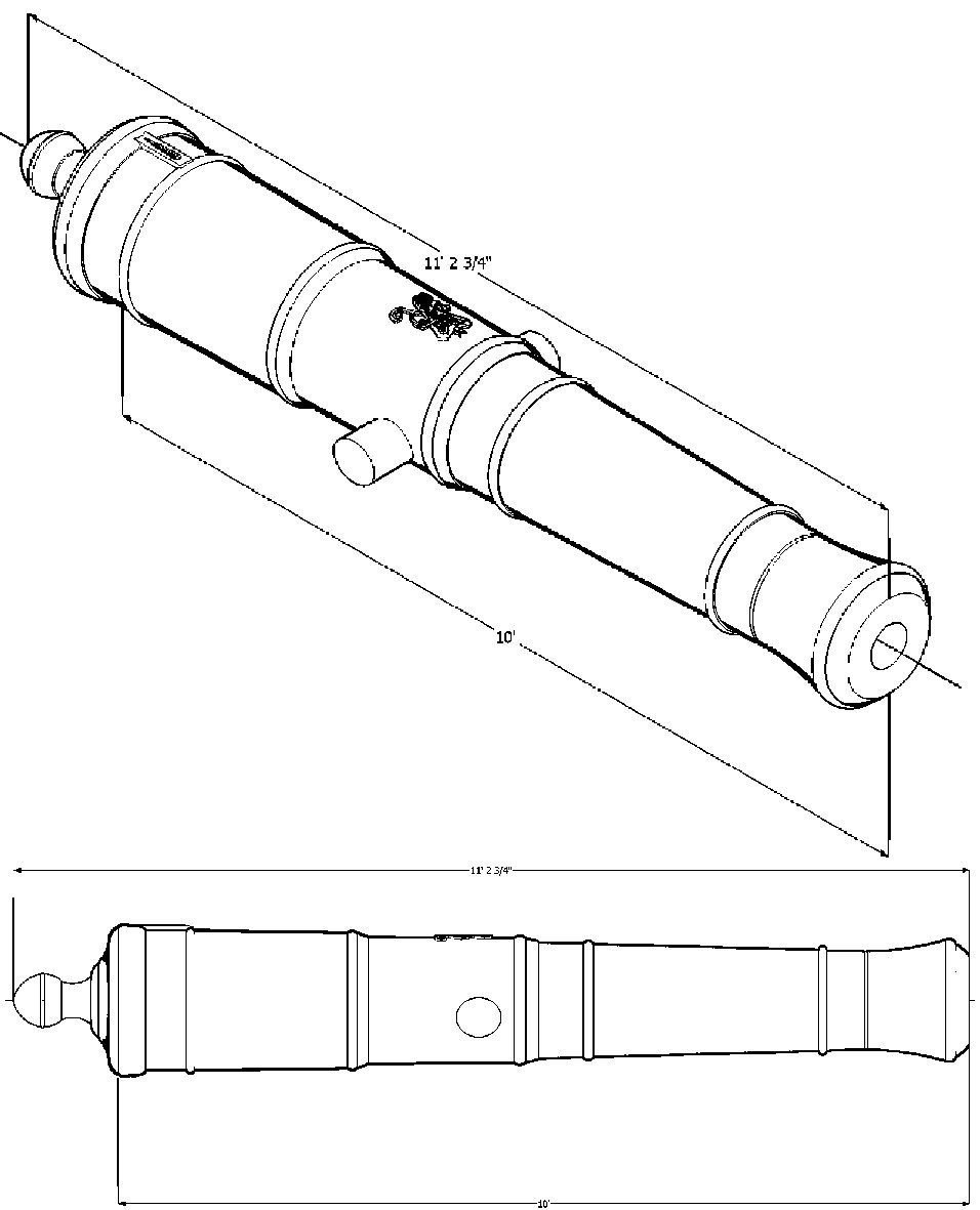
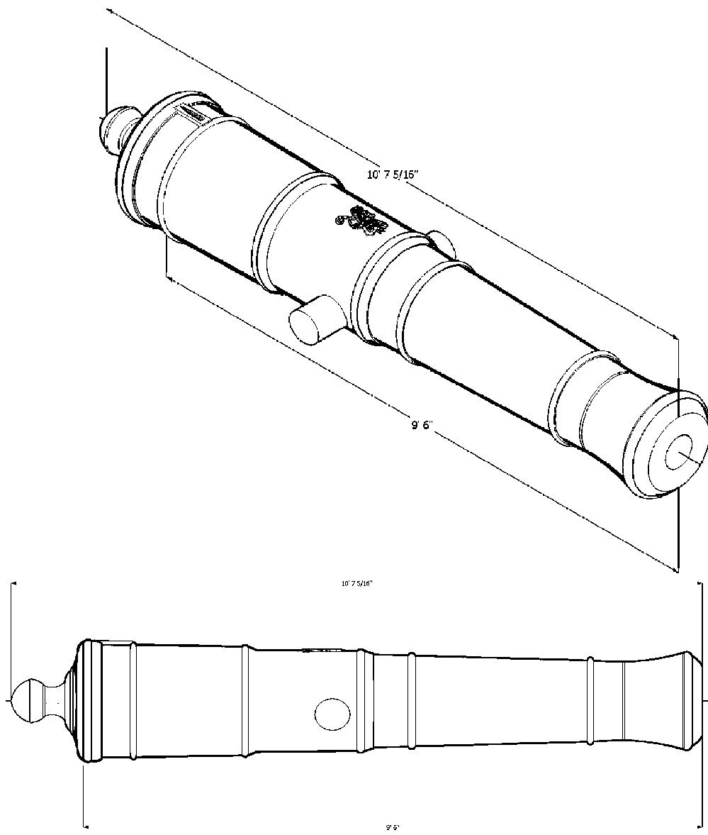
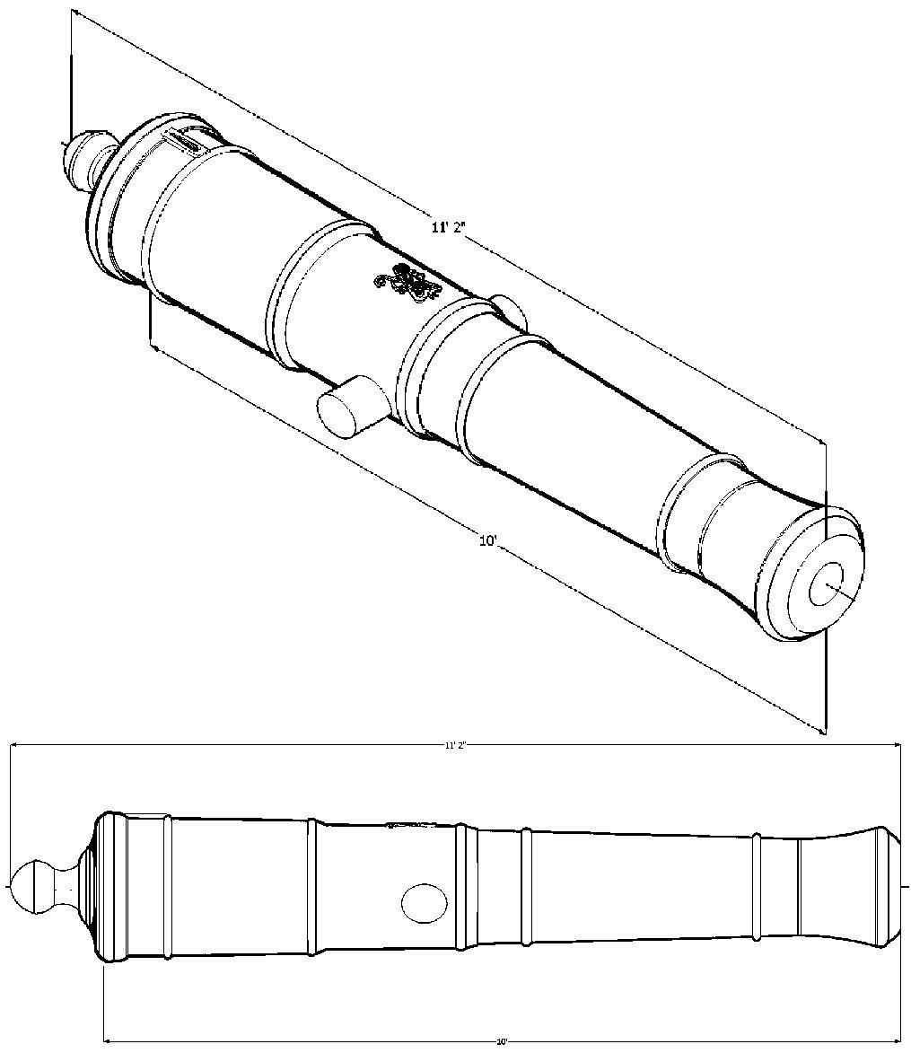
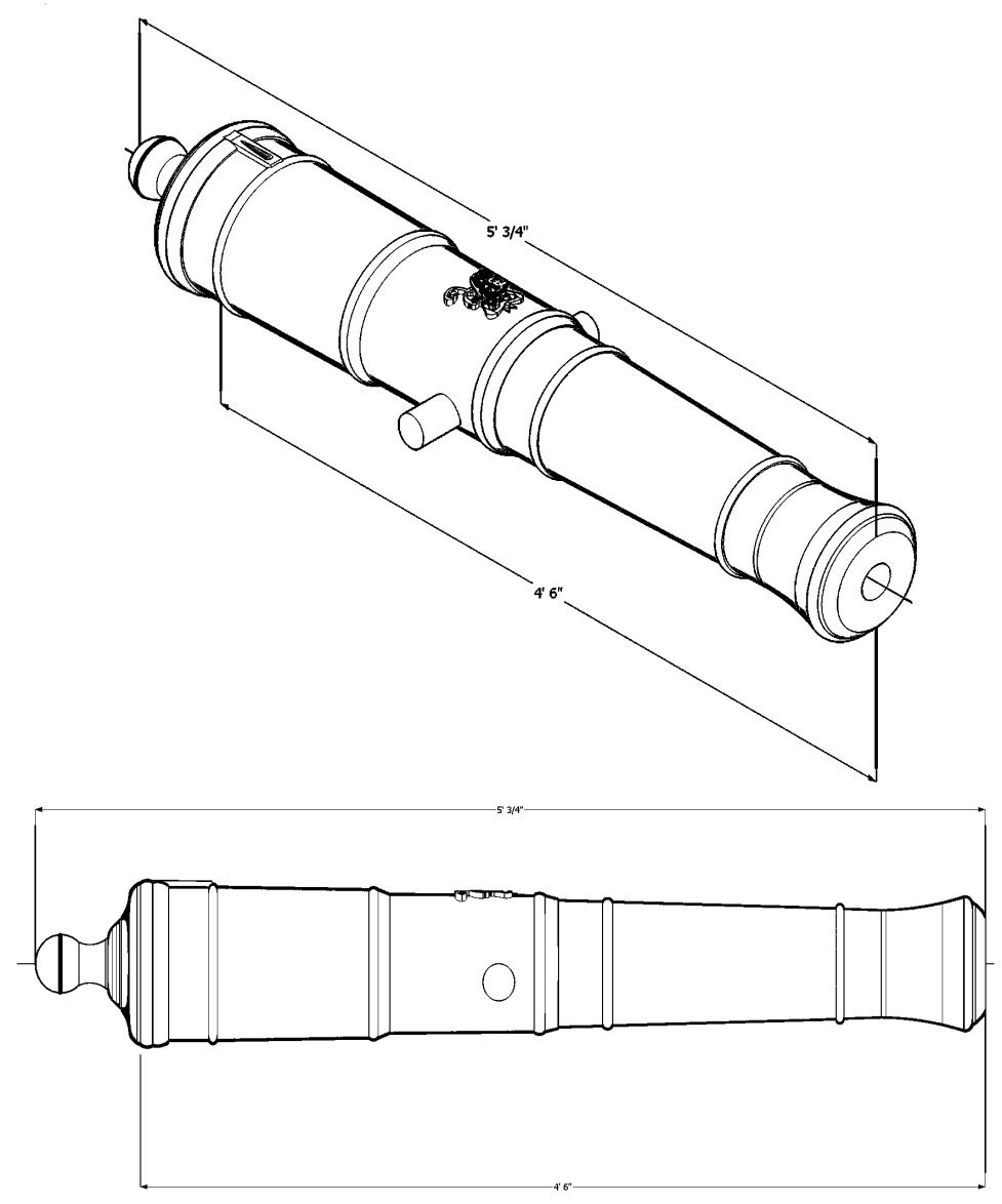
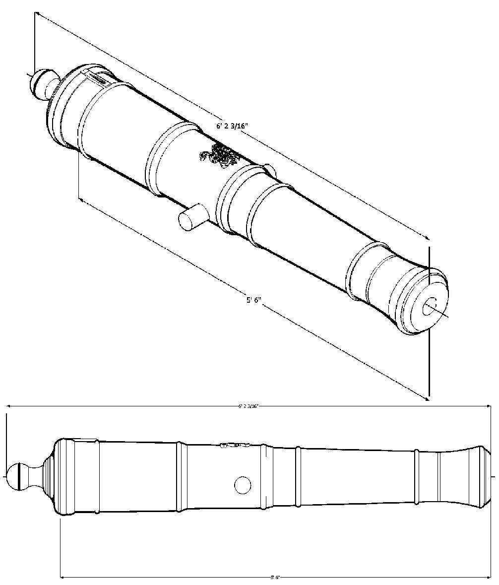
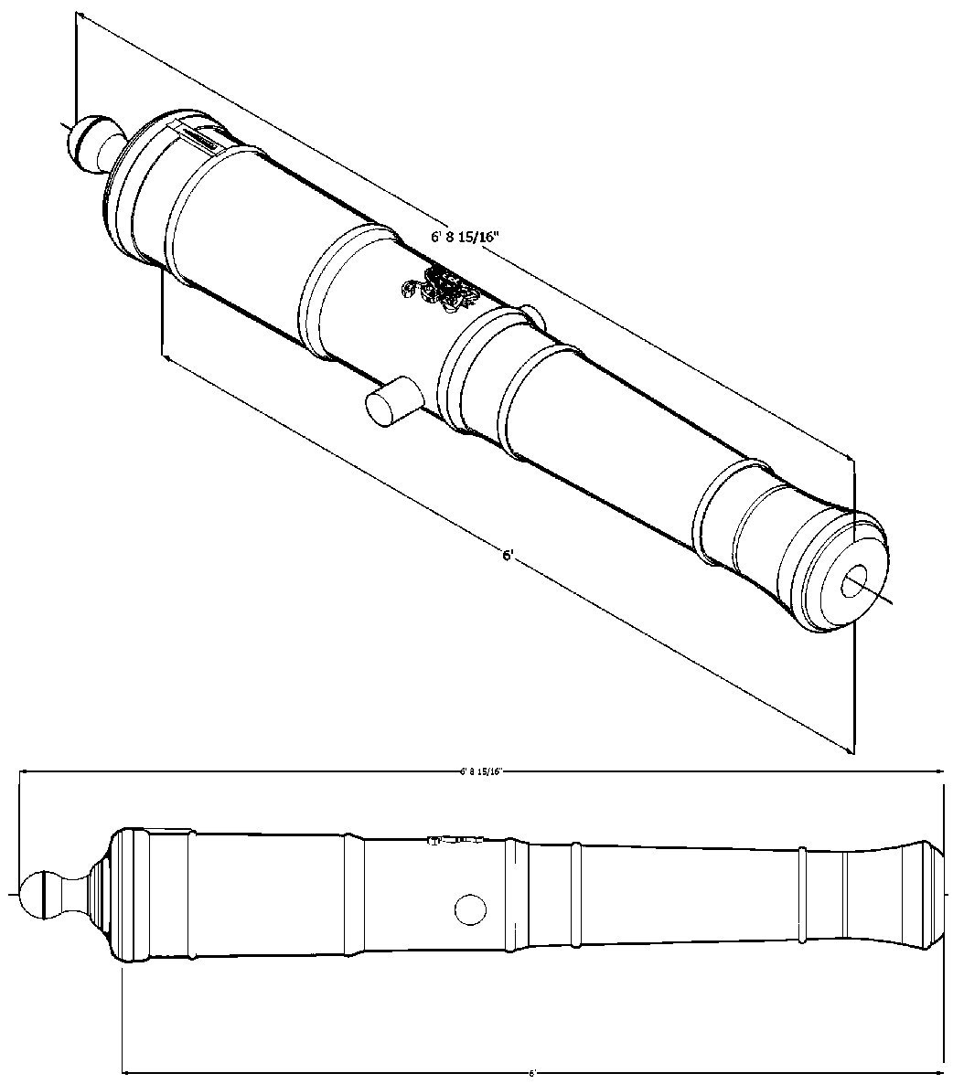
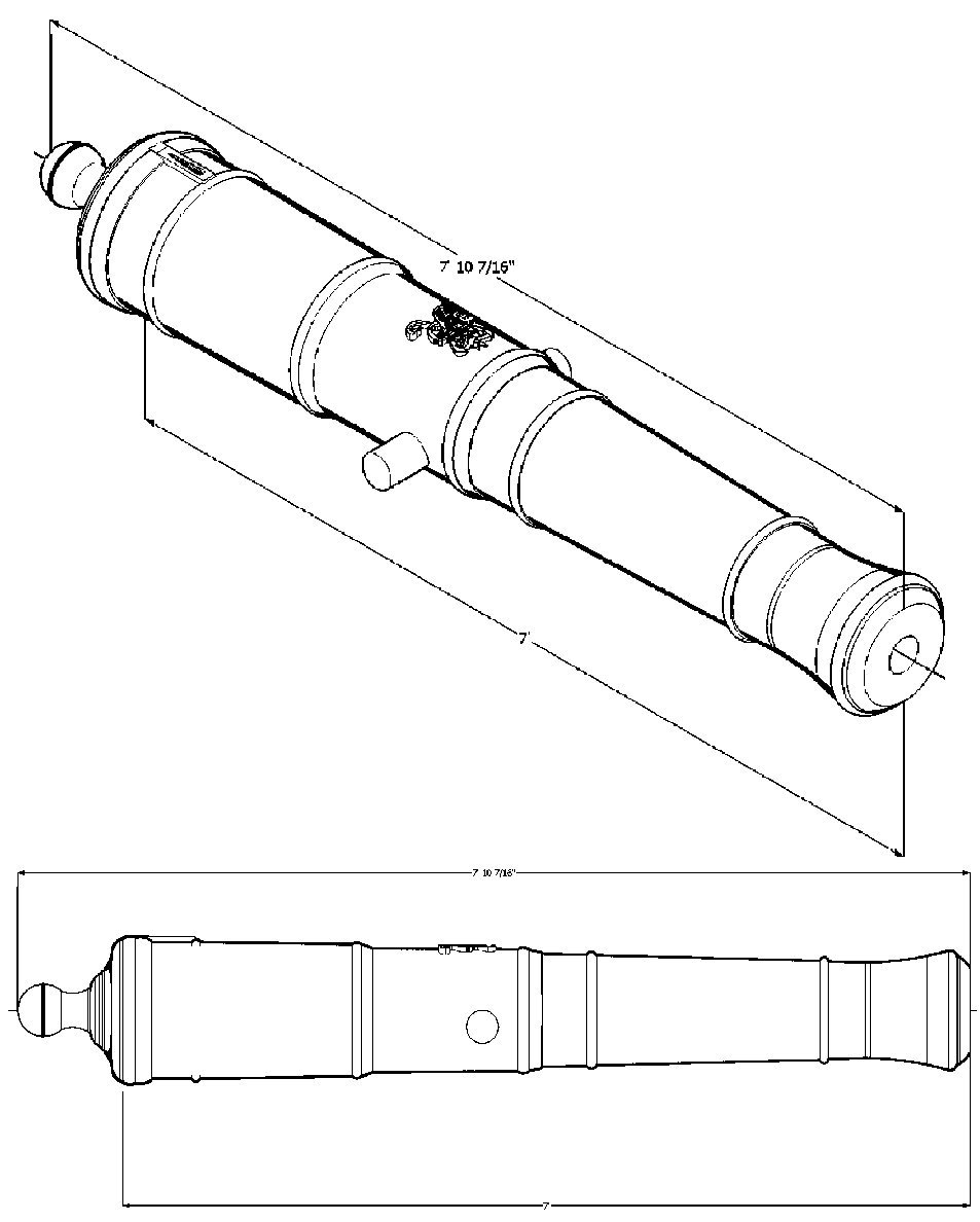
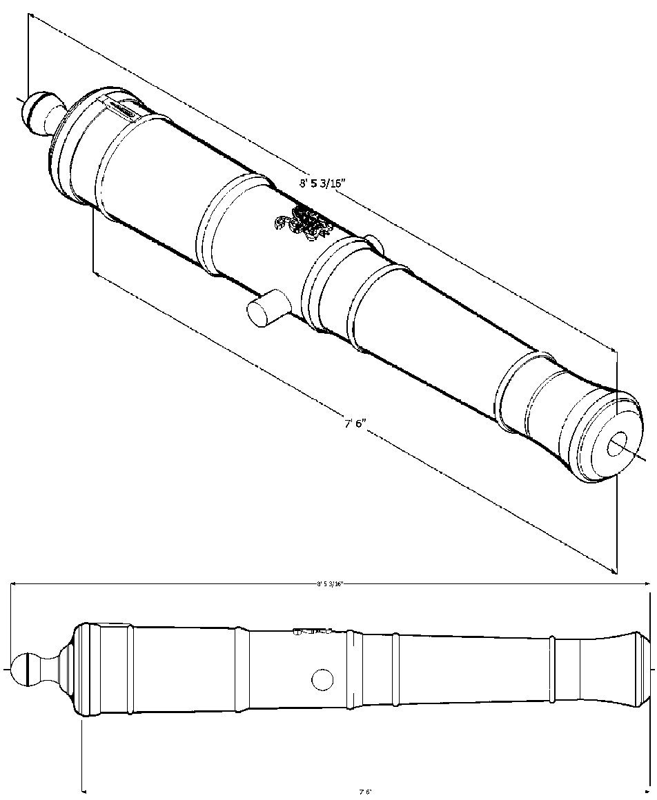
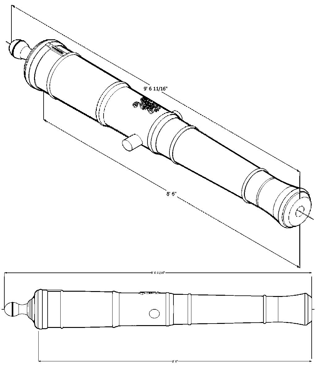
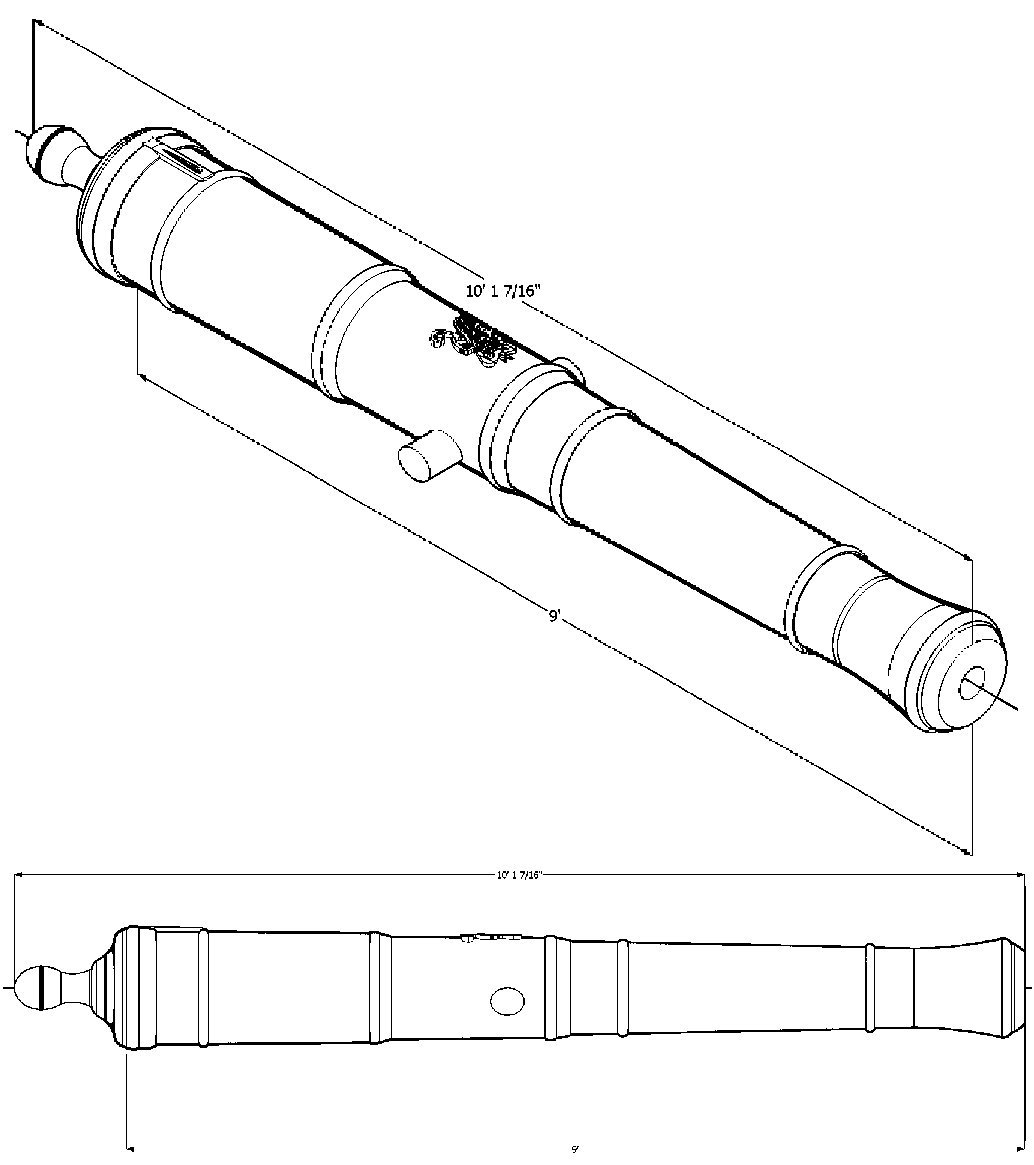
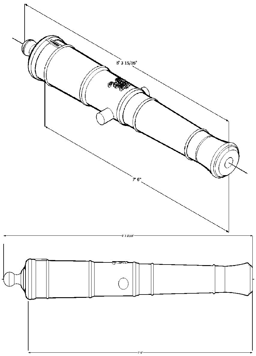
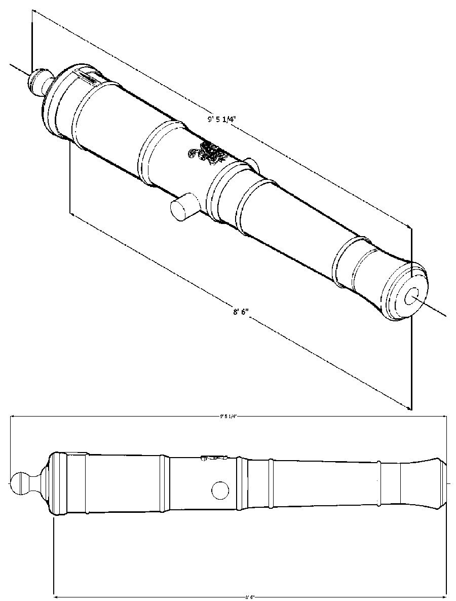
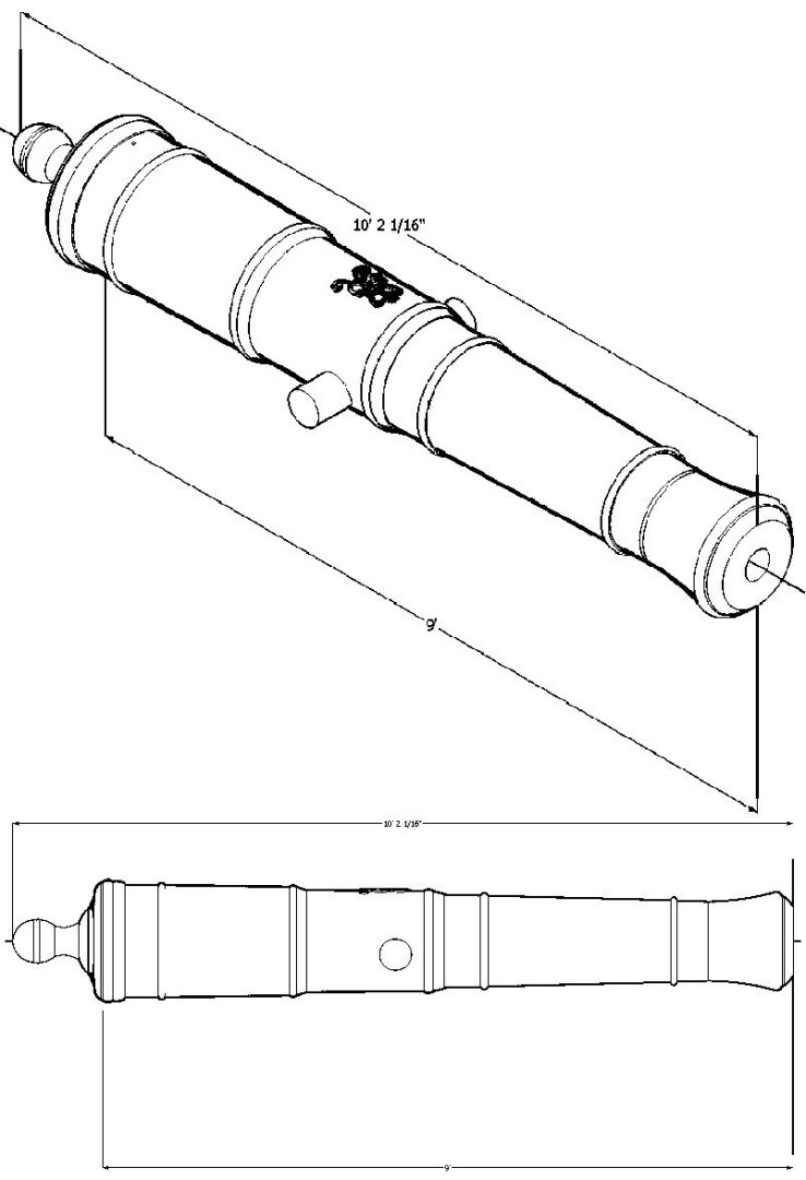
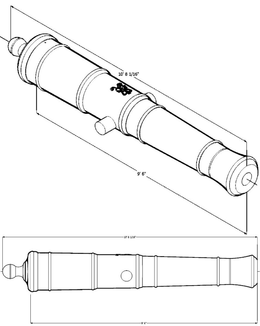
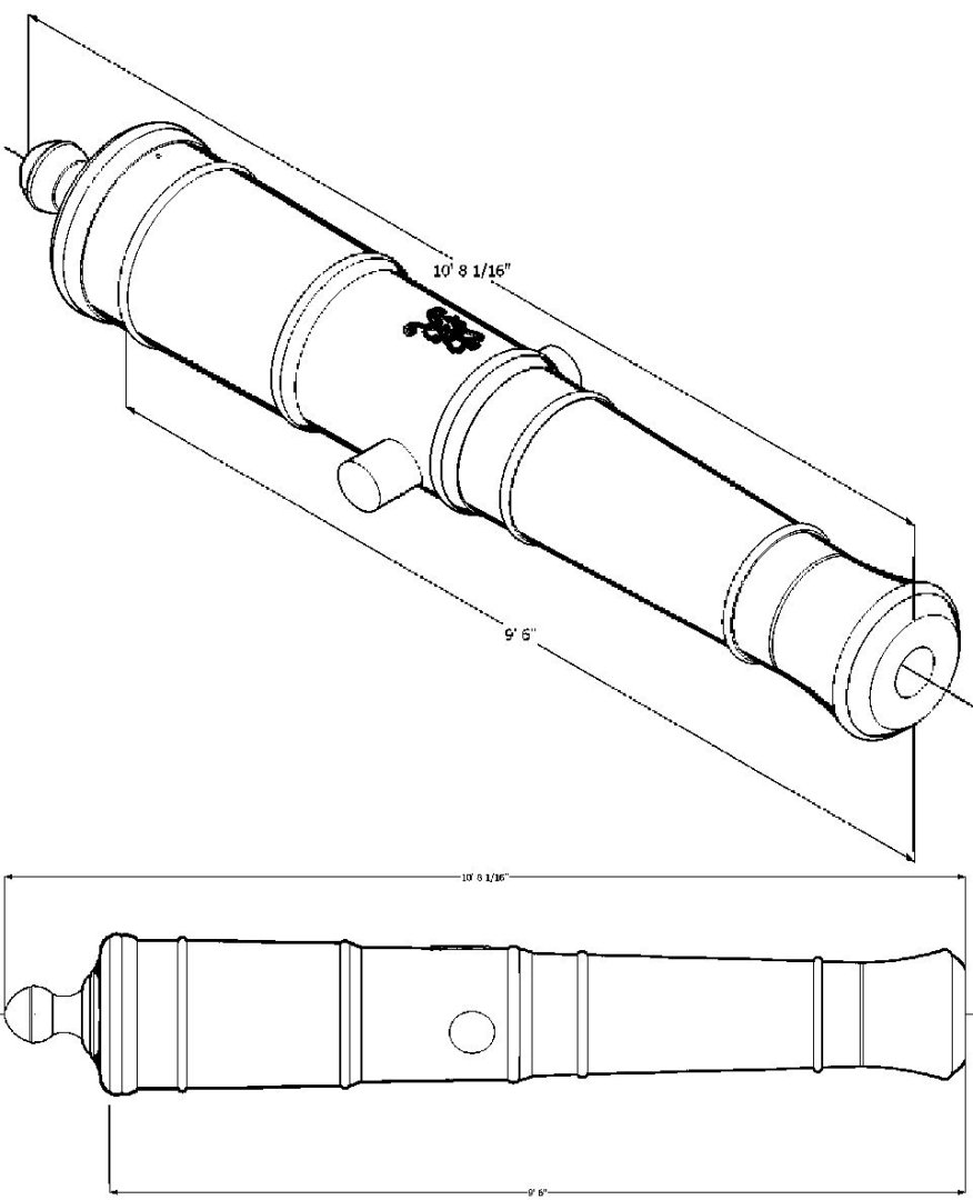
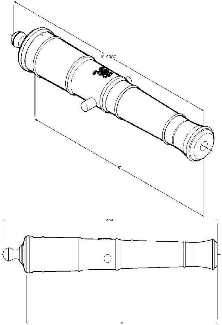
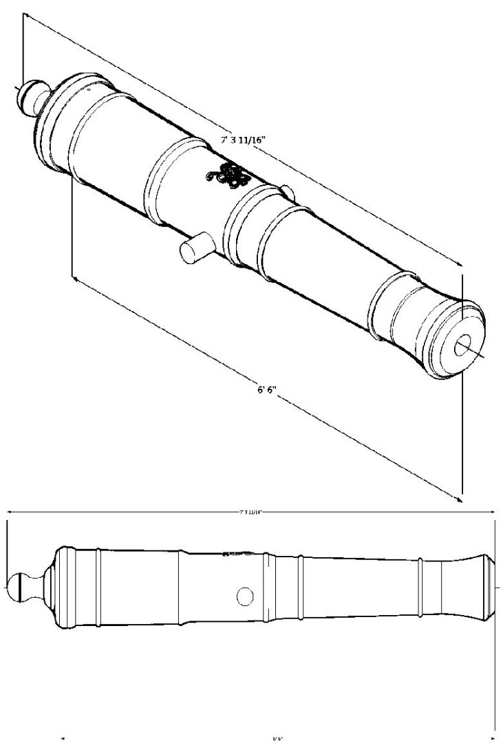
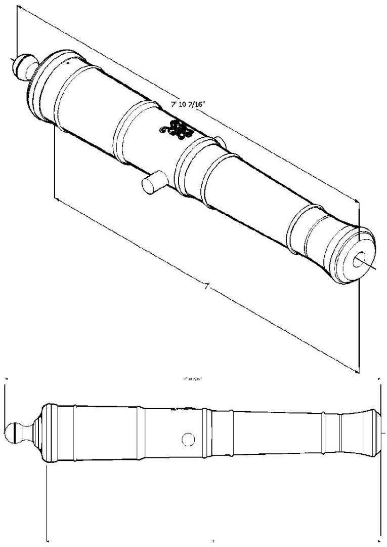
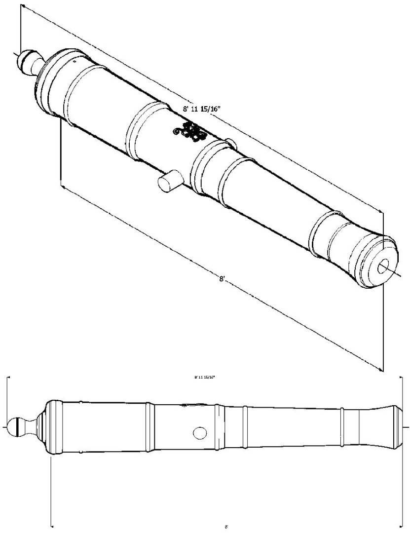
I finished redrawing the Armstong-Fredrick pattern cannons, using the specifications I found on the Web. They had pixilated drawings on the site and I used those to double check the results. The cannons now provide files for all the 3 Pounder to 42 Pounder cannons listed. There were additional sizes shown on the original drawing I used, so I've left them in this set. Over the next few days, I will generate the 3D files for all the cannons. The measurement shown in the graphic labels are the barrel length, not the overall length.