HOLIDAY DONATION DRIVE - SUPPORT MSW - DO YOUR PART TO KEEP THIS GREAT FORUM GOING! (89 donations so far out of 49,000 members - C'mon guys!)
×


thibaultron
-
Posts
2,944 -
Joined
-
Last visited
Content Type
Profiles
Forums
Gallery
Events
Everything posted by thibaultron
-

3D Printing Cannons in Resin
thibaultron replied to thibaultron's topic in 3D-Printing and Laser-Cutting.
I've updated many of the files in this thread, since they were posted. The NRG is in the process of placing all the cannon STL files in a database, that will be available on their web site, so stay tuned. -
I've updated many of the files in the Printing Resin Cannons thread, since they were posted. The NRG is in the process of placing all the cannon STL files in a database, that will be available on their web site, so stay tuned.
-
Sylvan Scale Models has several HO and N scale ship and boat kits. https://sylvanscalemodels.com/HO ships new page.htm Most of them are freighters, but some are smaller models. They have a steam tug, a couple unusual small freighters, a lumber freighter, and a very small freighter, as well as a set of "Fish Tugs". The Fish Tugs were small semi-enclosed fishing boats, used on the Great Lakes. in the 1900s.
-
I double checked my Cannonade drawings and have this also. Similar to what you showed. PM me.

-
I've 3D CADed a similar loop for the Blomefield cannons, so getting one like you showed is doable.

-
Do a search on Ebay, and then save the search. Ebay will send you a notice, if the kit is ever offered again. It took 3 years, but I managed to get a rare HO limited edition model depot/station that way, as well as getting many other OOP items (with much shorter wait times), over the years.
-
Just be careful not to buy a model that comes in a box big enough for her to hide the body in!
-
The advantage of S.A.B.L.Es are that you have a large selection of subjects to choose your next project from.
-
Chuck, I have created 3D files for the Armstrong and the Armstrong-Fredrick cannons. If you would like I can send you the files. They have the correct Royal Cyphers, for the period of each type.
-
At 692 feet long, that would be a large kit in most any scale! Even in 1/196th scale, it would be over 3 1/2 feet long!
-
Brass wire: it bends, it breaks!
thibaultron replied to Mollusc's topic in Metal Work, Soldering and Metal Fittings
You can buy Hard, Half Hard, and soft wire from Amazon, Ebay, and other internet stores. The wire is fairly cheap, I bought some of the Half and Soft, as future stock. -
Next Step In The Oil Bunker Project While I’m waiting for a print to finish, I continued working on the oil bunker. I made the changes to the print file I mentioned earlier, and added some features. The bunker has 3 grab irons and a handle for the sandbox lid. In the prototype the grabs and the handle are formed from steel rod, with the ends hammer flat, so that they can be riveted on. The 3D prints are too fragile to print these, so they most be formed from wire. To make this easier, I drew up a forming jig for the grabs, the hand rails, and a U-Shaped bracket that supports the rear fill hatch, when it is open. Why the detailed jig? Well, I will be making more bunkers in the future for other locos, and having the info on the jig, will help there. Also, I do have hopes of selling kits, in the future, so the better designed, the better kit. On the oil bunker, I added pilot holes for drilling the attachment holes, and flat pads to simulate the flattened ends of the grabs. I also made the holes for the handrail pilot holes a little larger, to aid drilling. I generated a file of a completed bunker, with all the railings, grabs, the support bracket, the steps, and the tool boxes all mounted. Here are pictures of a completed bunker, with all the bells and whistles. I have another print to do, after the present one finishes, then I’ll print the, hopefully, final design model.


-
I'm glad you told us this took 5 years! If, you had done all this in the last couple of weeks, I would have given up modeling, and sat in a corner jibbering for the rest of my life! 😆. Great work!
-
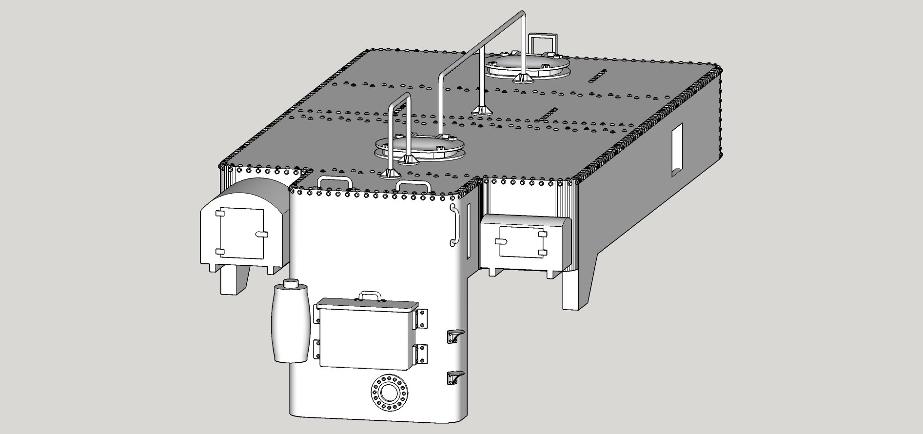
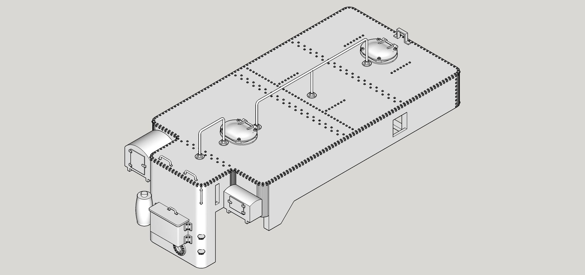
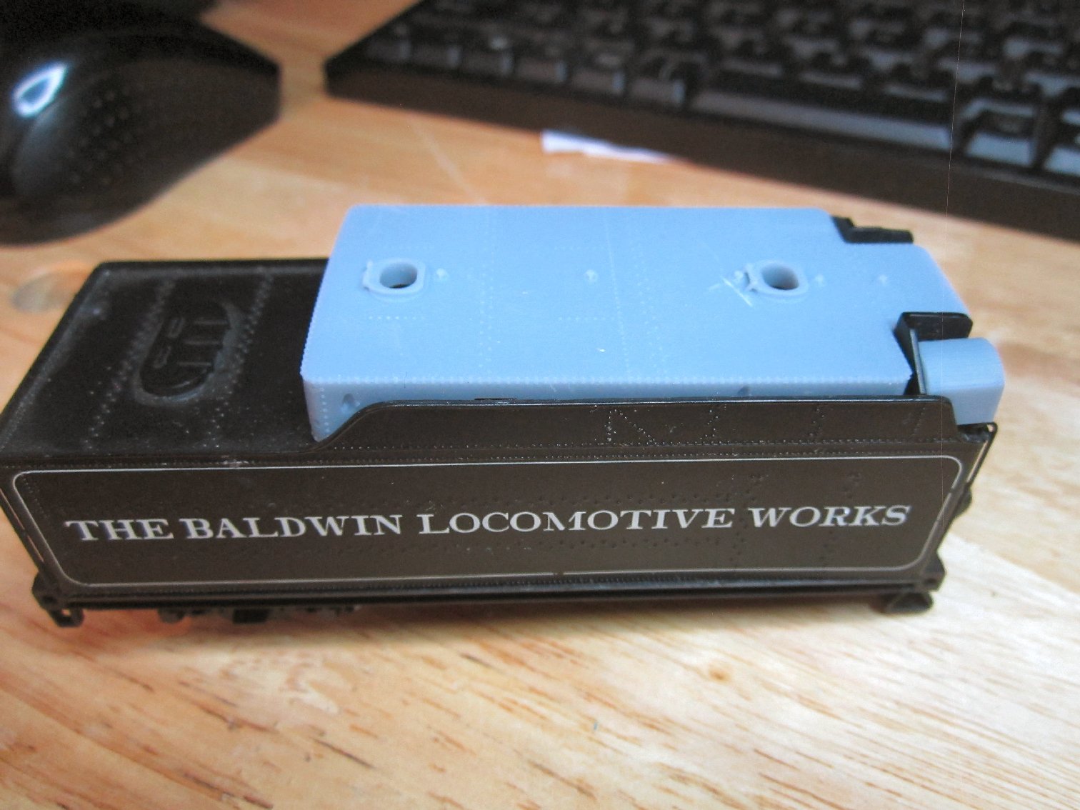
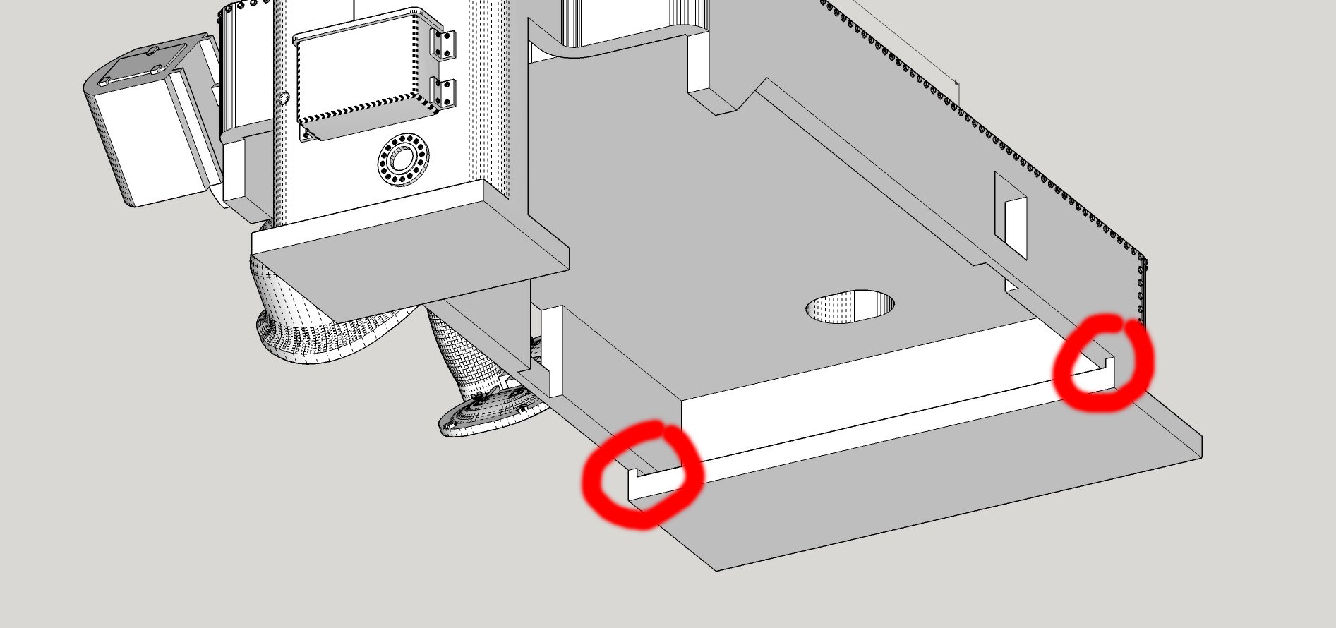
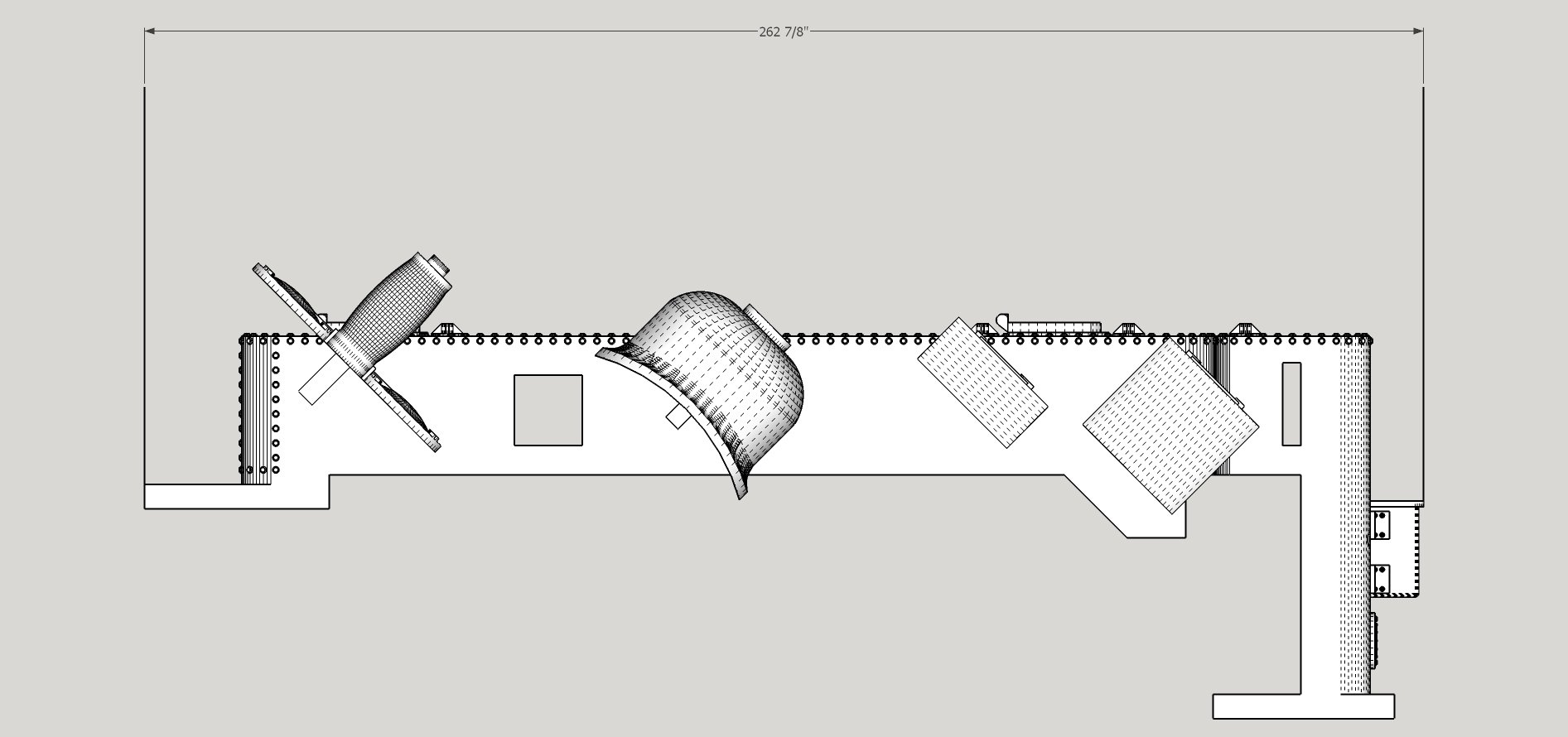
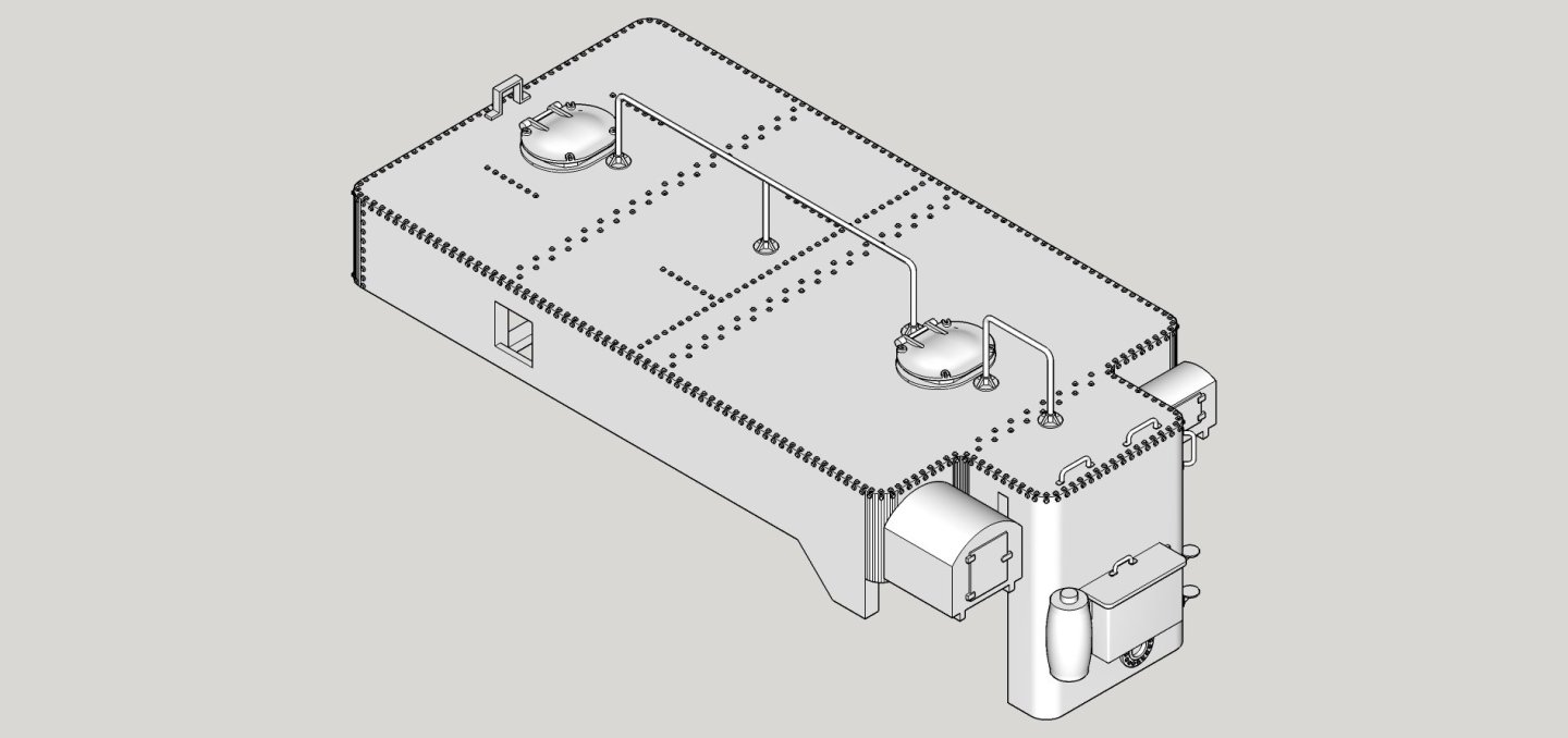
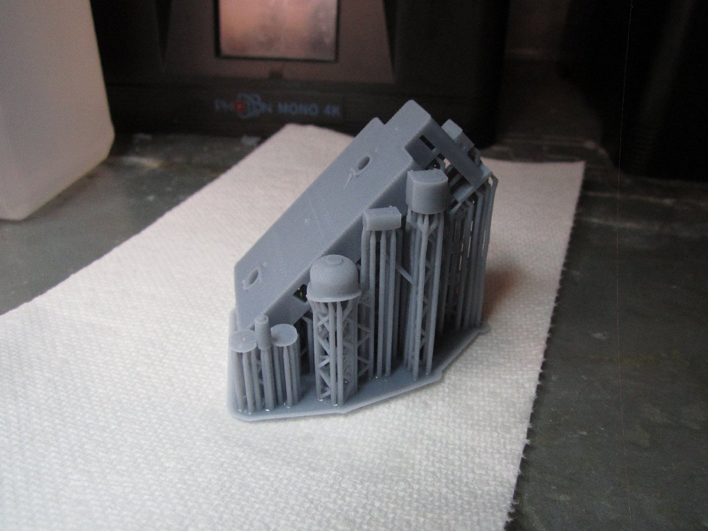
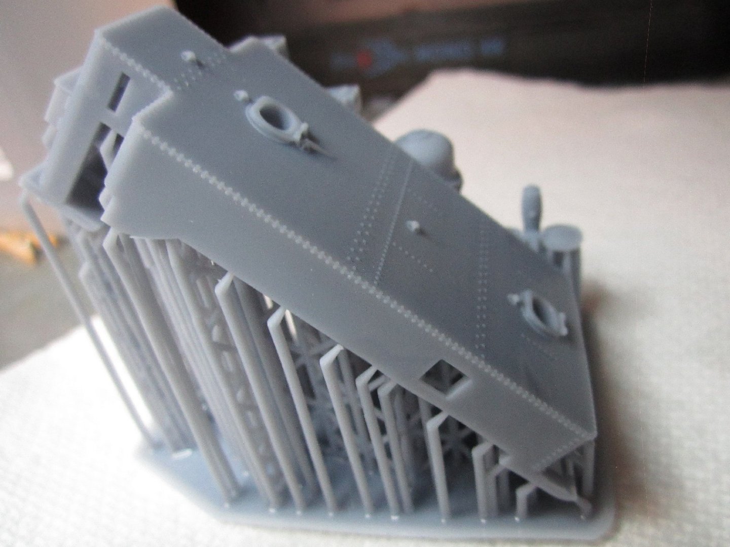
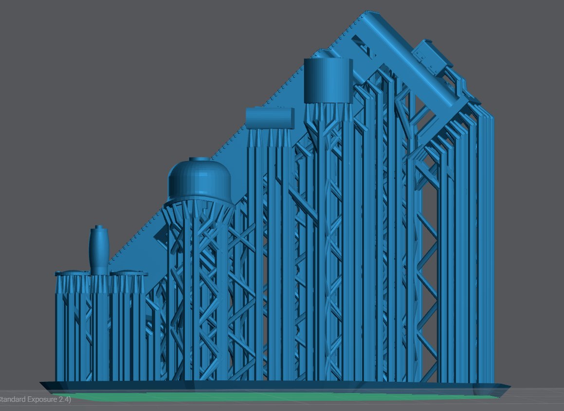
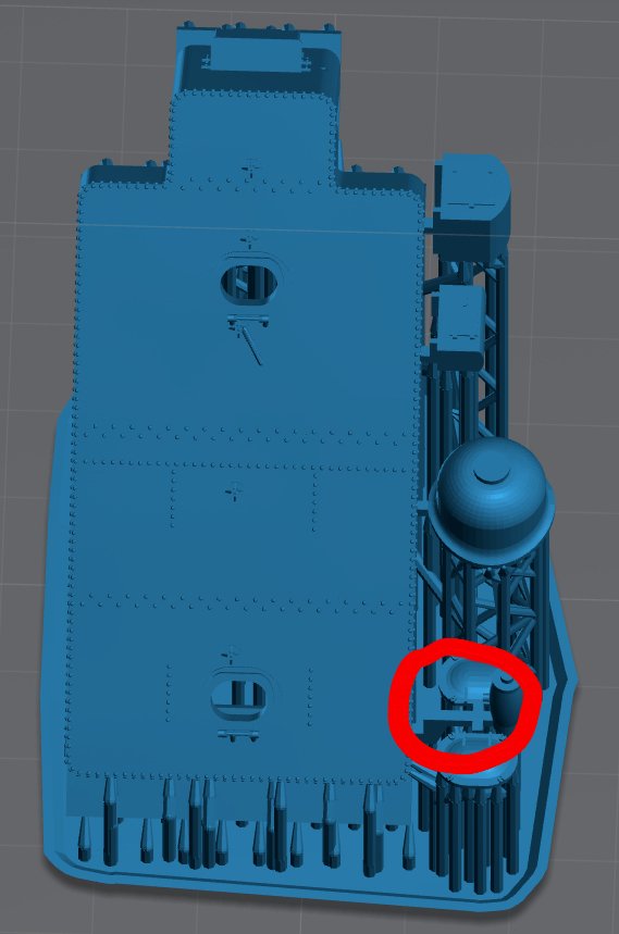
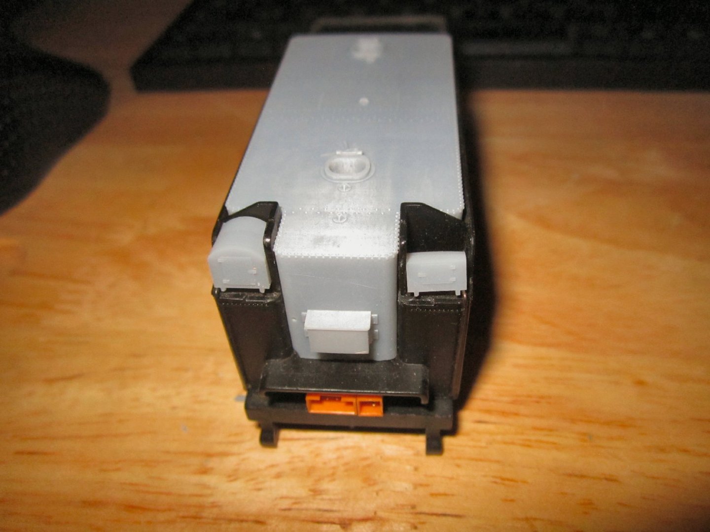
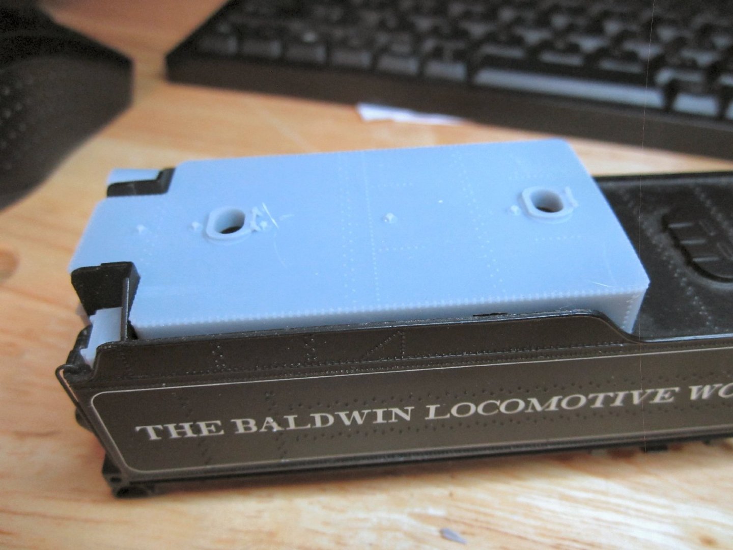
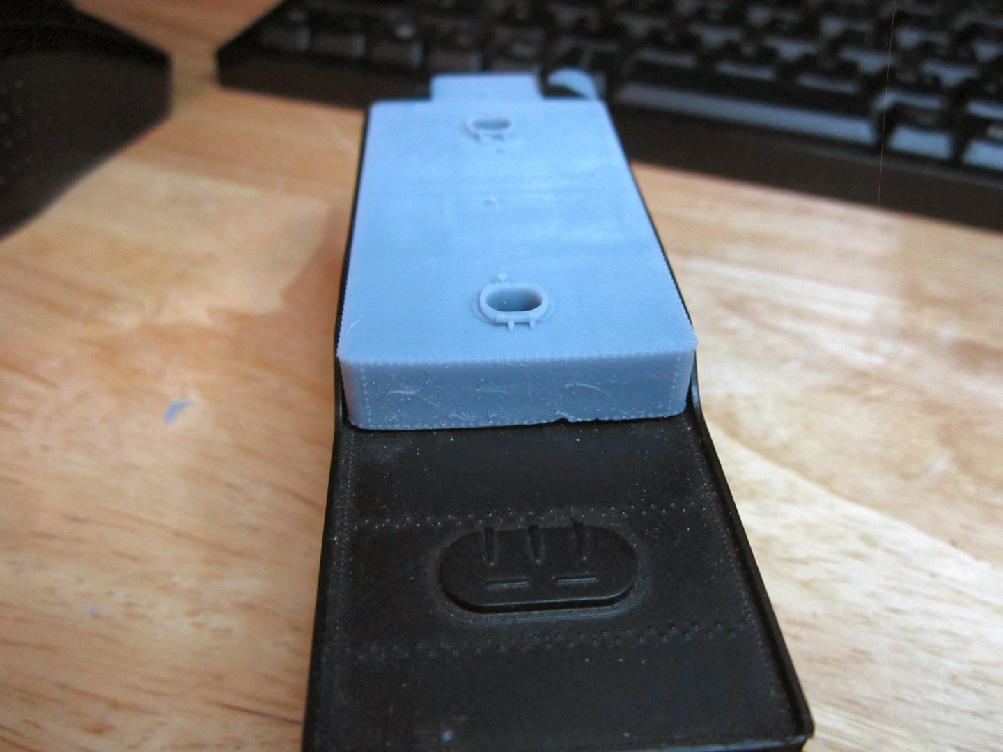
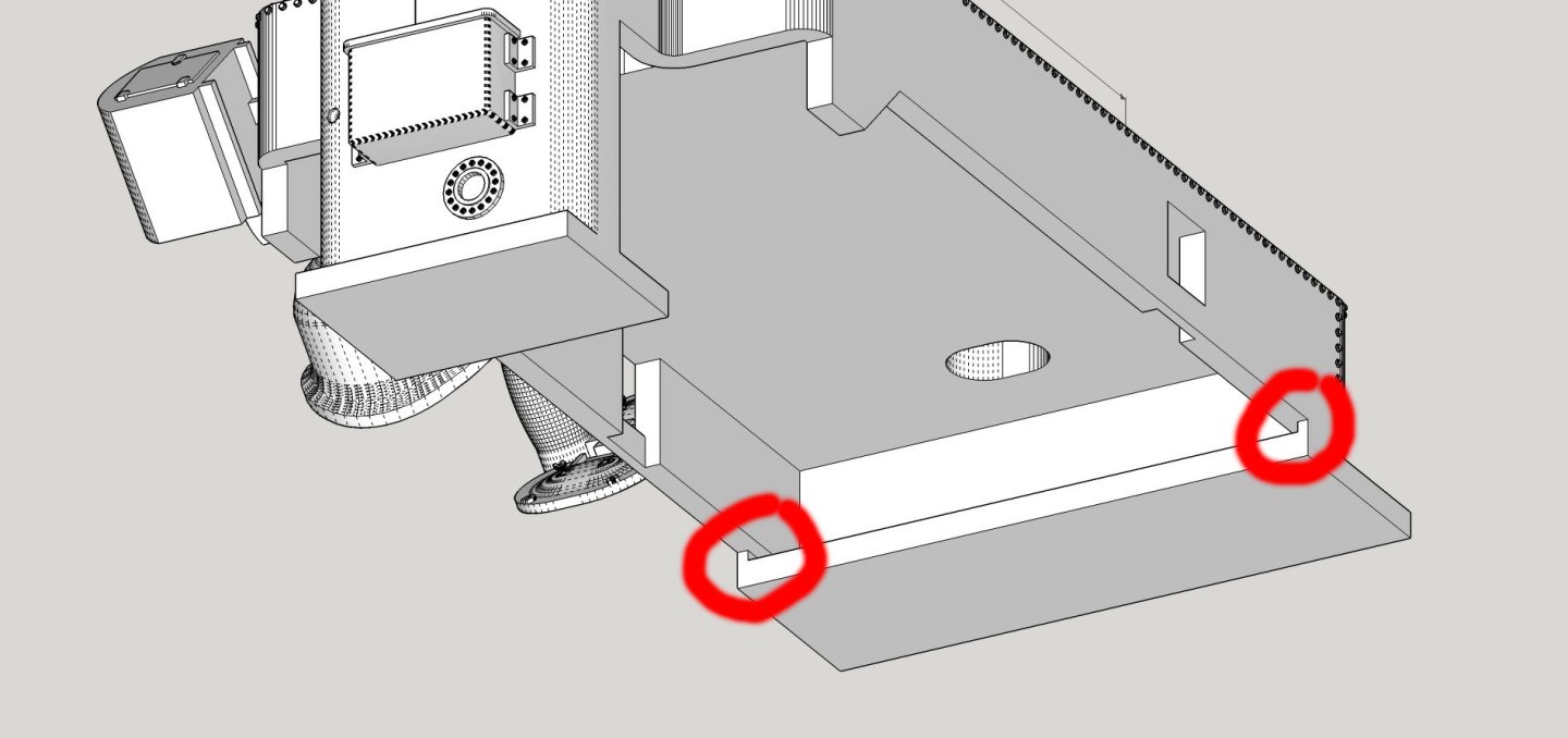
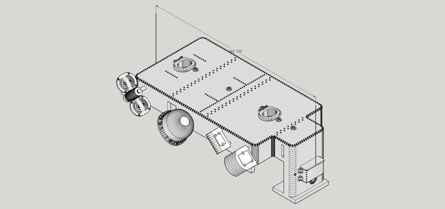
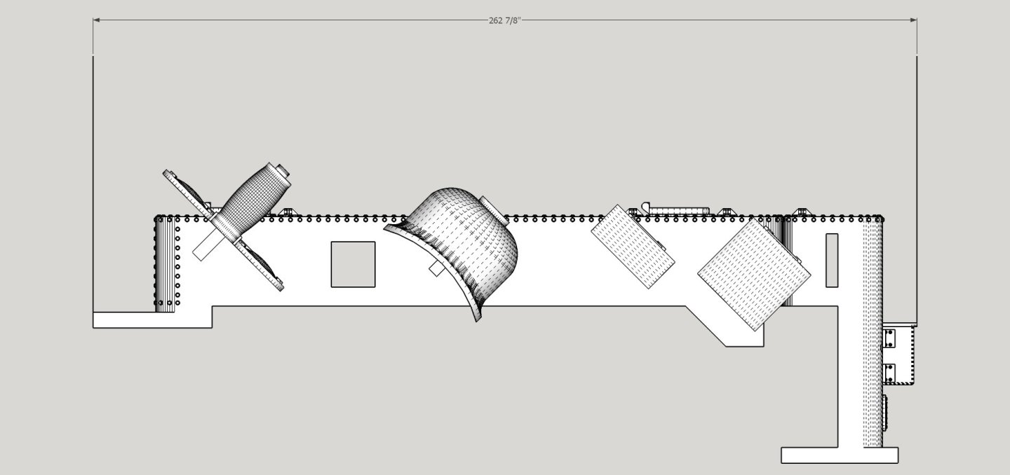
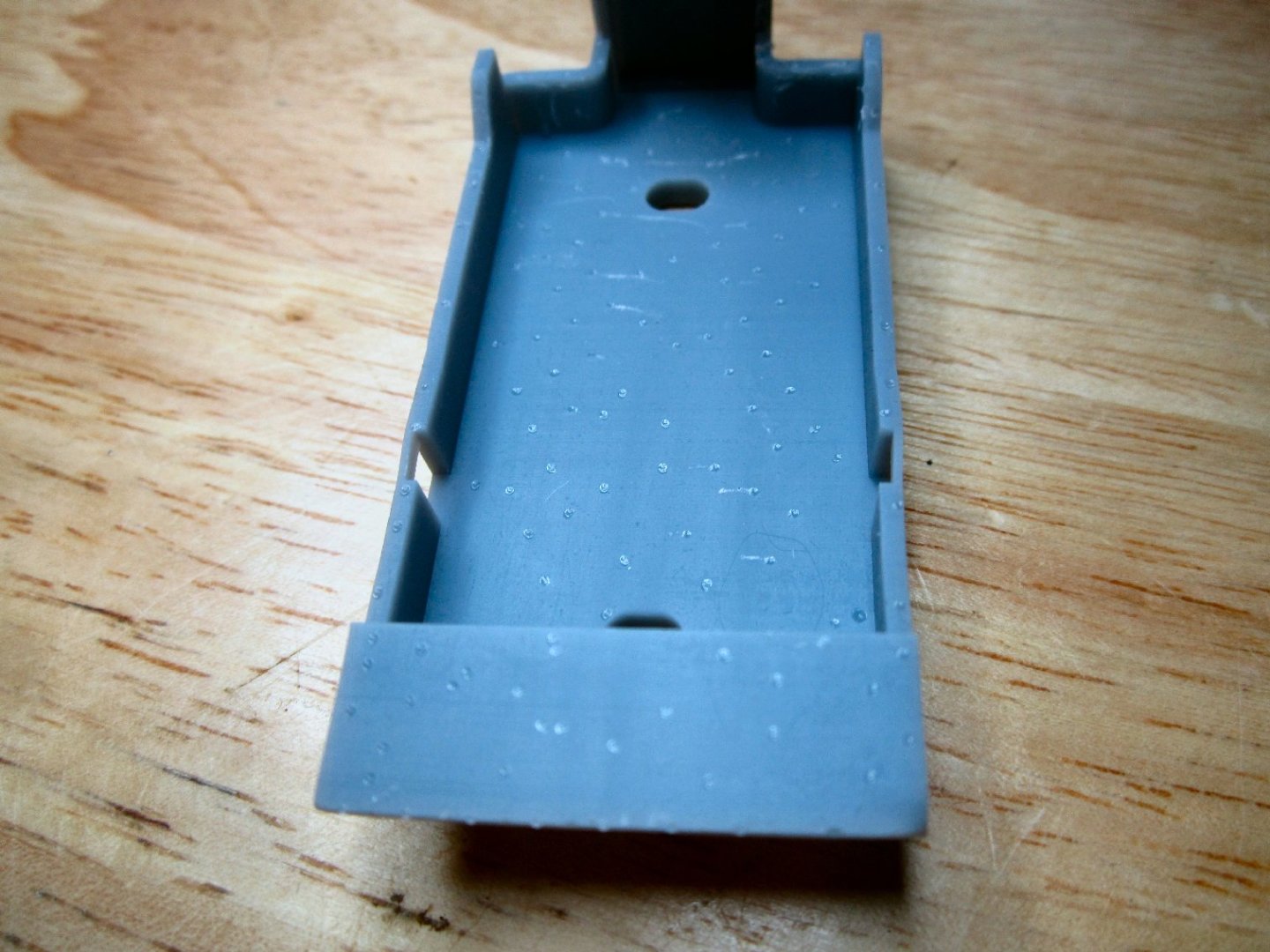
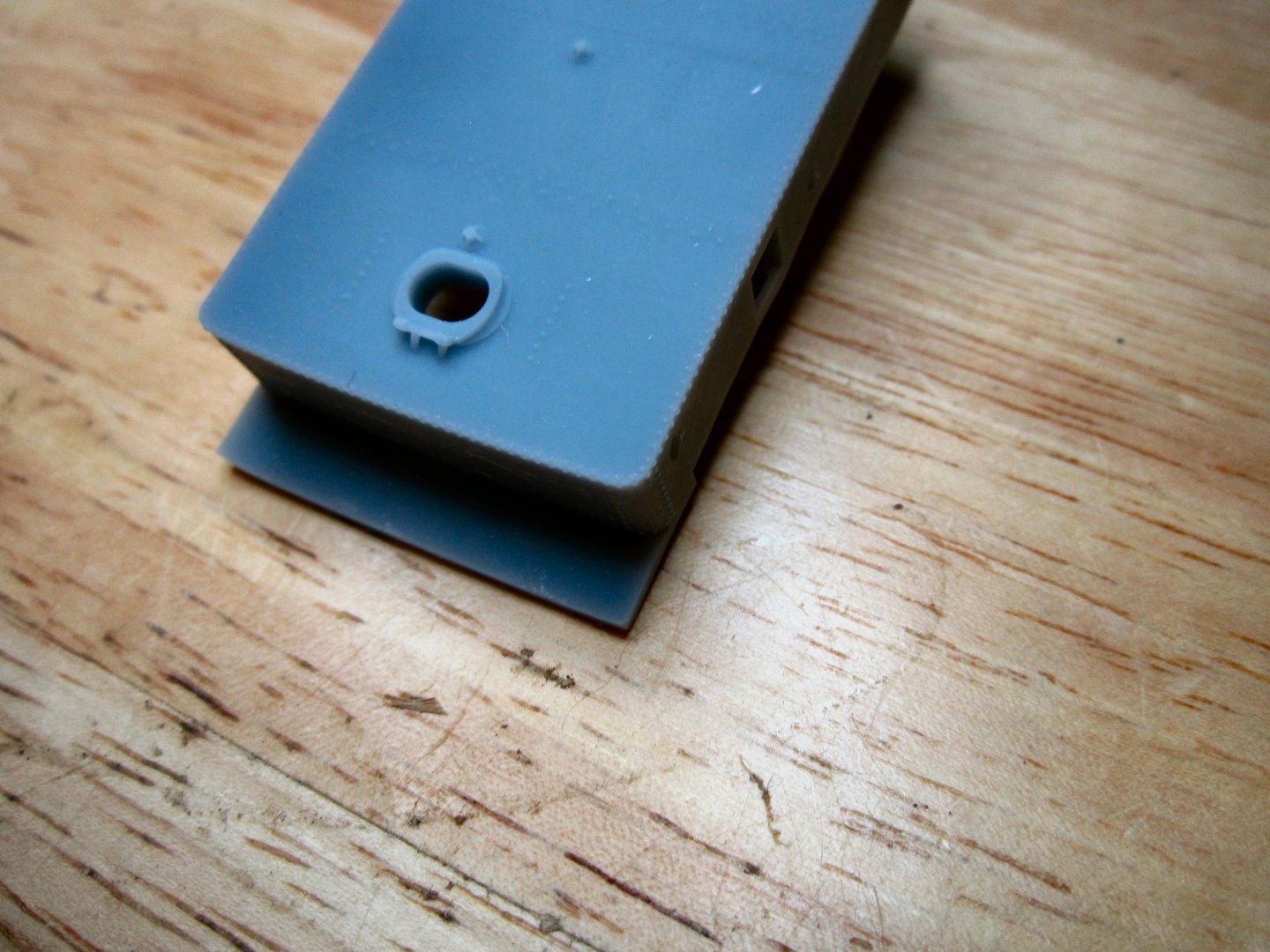
I finished a print of my Santa Fe Oil Bunker Insert, for a Bachmann 2-8-0 steam locomotive. The Santa Fe bought another railroad, and inherited several locomotives. The Bachmann model is close to some of the 2-8-0 locomotives they acquired. The biggest differences, are that the sand dome was different, and they were converted from being coal fired to oil fired. The Santa Fe had oil bunkers that would sit into the coal bunker, for this type of conversion, and a drawing of one is the basis for the model. I originally drew the oil bunker and printed it out using Shapeways. It took a few revisions but I had a good model. Then I found new information showing that my guess as to rivet spacing was wrong. I had spaced the rivets along the tank seems about half the correct spacing (i.e. 1.5” instead of the correct 3”). So, I redrew it with these rivets at the correct spacing. By now I had purchased a 3D printer of my own, and tried out the new drawing in it. It came out only fair, but proved that the printer could do the job. The main fault was that the rear wall of the bunker was distorting as the weight of the cantilevered model and forces from pulling the model from the film after each layer was printed had started to pull the model out of shape. Some of the other lower parts also suffered from this. I redrew the model with support platforms that were attached via thin walls to these areas, and reprinted the bunker. This print just finished, and is a vast improvement! There is still a little bowing at the very top of the rear wall, not along the whole wall. And there is a slight distortion at the cutouts that give clearance over the model’s coal bunker rear lip. There was some damage to the rear wall when I removed the platforms, so I will have to thin the attachment walls to help with the problem. I also need to make those attachment walls a little taller, to give me more room to use the razor saw to cut them off. This version, of the model is useable though. Since I have the printer, I’ll make final corrections and print out a new model, to actually put on the loco tender. Here are a couple of graphics showing the present model. The smaller pieces are at a 45-degree angle as the model will be printed at this angle to increase the resolution of the fine details. The model was printed at a 35um layer height, to match the 35um pixel size of my printer screen. If I printed it flat, my printer leaves some visible lines between some layers, and doing it at 45 eliminates this problem. In addition, printing it flat may rip the model off the build plate when it starts printing the top of the tank. It would also probably bow the top from the forces of detaching that large area from the film, after each layer is created. This picture shows the attachment walls of the platforms. The long overhang of the platforms is so any distortion in them will be stabilized when the printing of the bunker itself is started. Here are a couple of graphics of the supported model. In the first one you can see the small parts attached to the main body by small sprues. This works for the Shapeways prints (in fact it is required as otherwise each part would be a separate print, with each one incurring its own setup fee!). With the finished print these broke off while I was removing the supports. In the next print I’ll just let them sit level and not attached to the bunker itself. This shows a side view of the supported model. The leftmost “Tower” has the two oil fill covers and the crew’s drinking water tank. The next part over, is the new sand dome. The next two are the tool boxes that sit on either side of the bunker at the front of the tender. At the far right, attached to the front of the bunker, is a sandbox used by the fireman to occasionally throw a little sand in the firebox to help clean out the boiler tubes. The attachments under the sandbox are supports, not part of the finished model. Here are two pictures of the finished print. Each rivet is only a 1.5” hemisphere, full scale. In 1/87.1 scale they are 0.017” or 0.44mm in diameter and 0.22mm in height. So, the new resin printers give you fine detail! After I removed the supports the next two photos show the attached rear platform. You can see the slight bow in the top of the rear bunker wall in the second photo. The last set of pictures are with the bunker and toolboxes installed on the tender. The only modification that is needed to the tender, is to remove the separate coal load casting, which is attached with a screw. This picture shows the front of the tender. The color of the printed part, in this shot, is close to the actual color. The next photos are under shop lighting, not flash, like this one. The shop lighting shows the rivets a bit better. I have to check, I think I have the tool boxes on the correct sides, but they may be reversed. The hole just to the left of the sand box, is where the Crew Water Bottle goes. I did not install the water tank and oil fill covers for these shots, they need a little sanding, and I will do that later. The next two pictures are of either side of the installed bunker. You can see a divot at the rear of the bunker, where one of part supports broke off. This problem will not affect the next version, as all the small parts will be printed, unattached to the bunker. After taking these pictures, I noticed that the cutouts for clearing the tender coal bunker rear wall are a little too tall. I’ll have to fix this. The little spots you see running along the center length of the bunker top, are stanchion bases for the handrails. I’ll make these out of brass rod, for the final model. I also plan to design and print a bending jig for the rails. The last photo is the rear wall of the bunker. You can see the section that broke off, while I was removing the platform. It has taken me a long long time to draw up this bunker model, and I could have probably hand built one in the time I spent on this, but I can now use the drawing as a basis for other types of locomotive models that need the same conversion. I have another Bachmann 2-10-0 that will need a variant of this tank, and at least one brass locomotive.

-
I would guess they were gilded, covered in gold leaf. They would lay some sort of adhesive/varnish on the wood, then place gold leaf sheets on the wet whatever, burnish it down then varnish over it to seal it. So they were not solid gold, but covered in a very thin gold coating.
-
Atlas craftsman lathe
thibaultron replied to kgstakes's topic in Modeling tools and Workshop Equipment
I don't know if this is an original chuck, but it is a standard 3-jaw type. 3-jaws have 2 sets of jaws, these for holding larger pieces by clamping on the outside of the piece, and another set that step in the opposite direction (hiighest level toward the center) for holding smaller pieces on the outside and hollow pieces on the inside. If you don't have the other set of jaws for this chuck, you, unfortunately need to buy a new chuck. The jaws on 4 jaw chucks are reversible, so only one set is needed. The advantage of a 4-jaw is that it can hold non-round pieces, as well as round ones. The disadvantage is you have to manually center each piece. A 3-jaw automatically centers round stock. The tradeoff of the 3-jaw, is that it does not perfectly center the piece. If you need the part perfectly centered, you need the 4-jawYou really need both types to get full use of your lathe. -
Atlas craftsman lathe
thibaultron replied to kgstakes's topic in Modeling tools and Workshop Equipment
Yes a zinc blend. They are delicate in order to break sacrificially, rather than have the rest of your lathe break, if a problem occurs. Head stock gears and housings, or the cross slide internals, are a lot harder to replace, if a tool jams in the work. Still they will last a long time in service, as long as this does not occur. When adjusting them, place a piece of paper between each gear and the next, then tighten the mounting bolt. If you run them closely meshed they will wear quickly. The slop will not mater during cutting, as the slack will be taken up when you start the cut. Repeatability is the watchword. As long as everything works the same each time, great precision in gear mesh makes no difference. I highly recommend buying the Atlas lathe manual. While it is written for the larger lathe, the functions all scale. -
Sorry 14 volts for a 12 volt lead acid.
-
What type of battery? If lead acid, they charge to about 14. Other types I don't know.
-
Just wire both motors to it, reversing the wiring on one, if you have counter rotating propellers. Certainly your motors don't draw more than 20A each, unless you want to melt the boat.
-
Chris; I must have missed this in your prior builds. What do you mean by sealing the parts?
- 146 replies
-
- 1
-

-
- Speeljacht
- Seahorse
- (and 2 more)
-
Guys, these were going to be 1/32 to 1/64th scale figures! Many of the things you pointed out would be hard to see on a 1/6th scale figure!
-
Here in the US, drywall has a paper surface that you can paint on directly. You still need to tape the joints, and screw/nail holes, though.