HOLIDAY DONATION DRIVE - SUPPORT MSW - DO YOUR PART TO KEEP THIS GREAT FORUM GOING! (Only 66 donations so far out of 49,000 members - Can we at least get100? C'mon guys!)
×


thibaultron
-
Posts
2,941 -
Joined
-
Last visited
Content Type
Profiles
Forums
Gallery
Events
Everything posted by thibaultron
-
 For those interested, I've started a log on the process I went through to go from the 2D drawing to the 3D part. "Going From A 2D drawing To A 3D Printed Part Tutorial"
 -
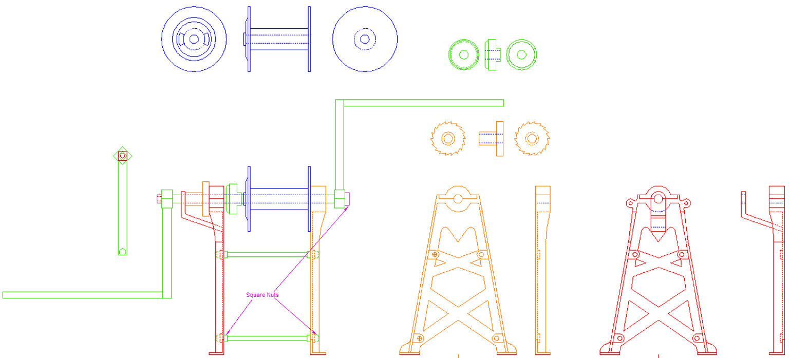
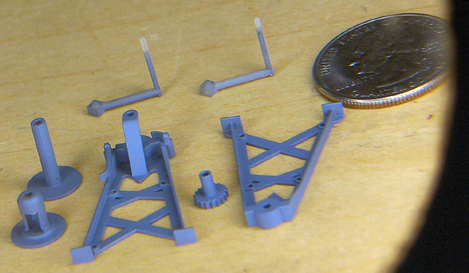
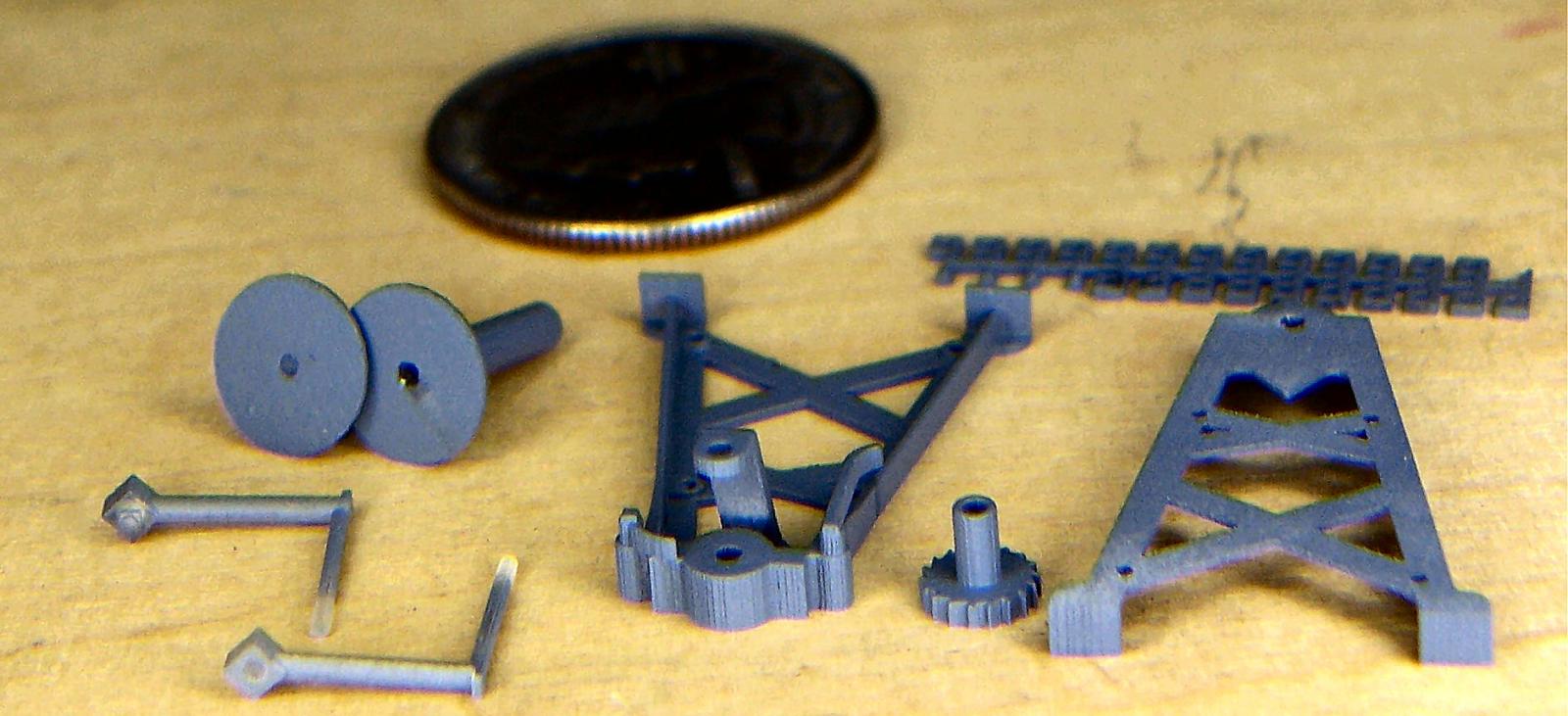
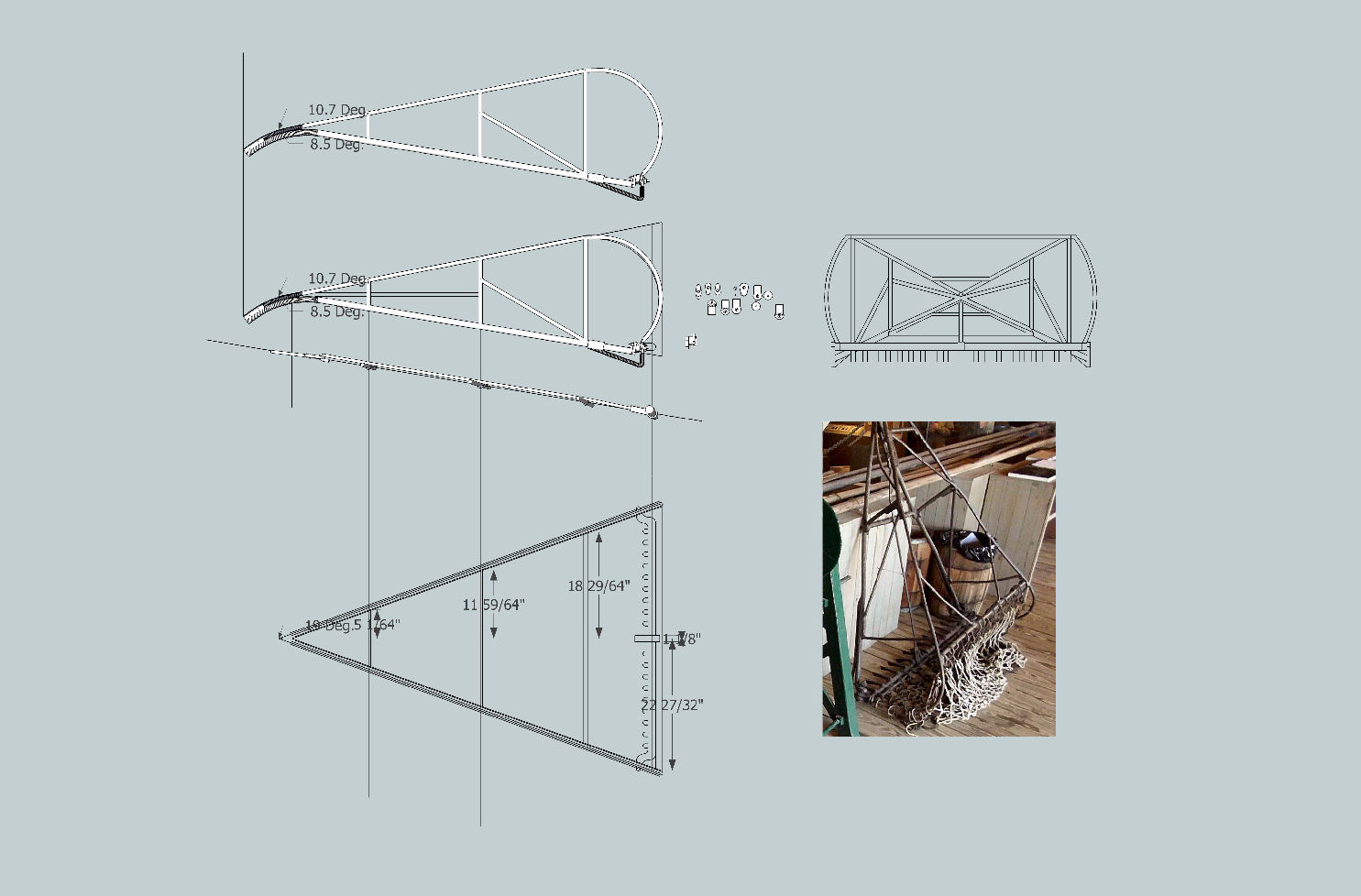
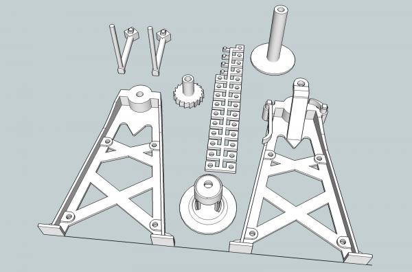
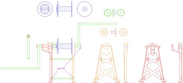
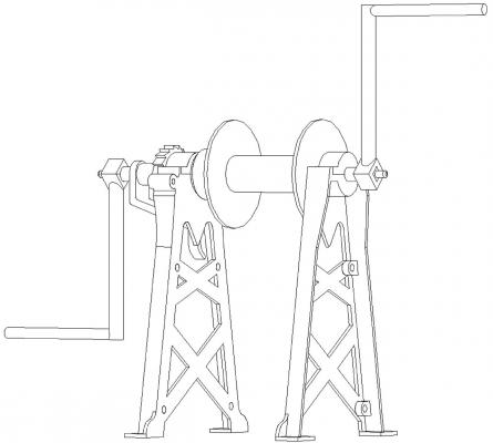
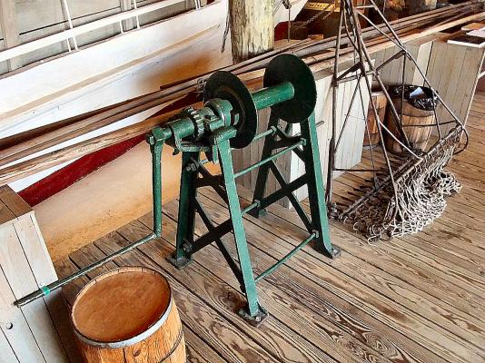
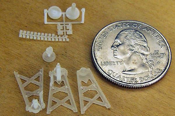
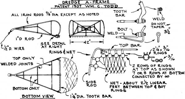
Part 01 Please forgive me for any typos. This log will be my journey from a 2D drawing to producing (well having printed), a 3D model. The subject model is a Hand Cranked Oyster Dredge Winch. These were used on Chesapeake Bay oyster dredges, before the advent of gas engine driven winches. The winches are used to pull in the dredge after it has scraped the oysters from the oyster bed. The original winch was about 36 inches high at the crank/drum axle. The original winch parts were castings for the major components. Here is a photo of the winch at a museum, with a dredge frame behind it. Here is a picture of the finished 2D drawing (the crank handles are still too long, I corrected this in the 3D SketchUp drawing), and a 3D projection, of an earlier version. Why didn’t I just go from the 3D CAD to a 3D printed part? For the 3D CAD drawing, above, I had developed it using just proportions, and some guesses. A friend, then sent me some rough dimensions, and I redrew it. The 2D drawing is of this final version. I decided to go directly from this drawing to SketchUp, a dedicated 3D solid CAD program. There is a free version of SketchUp, that I used for the majority of the drafting. The only real function it lacks is the ability to import DXF files, a standard CADing file type. I have an earlier Pro version, that I used for importing my 2D drawing. It also lacks some 3D solids Boolean functions, but these are not needed, you can do them yourself, it just takes a little more work. Parts you generated based on a drawing, which are generally “Extruded” from the 2D lines to give them height (You’ll see what I mean later), can’t be operated on by these functions anyway. The free version of SketchUp, can however, import graphics files, so you could either use your CAD program to create a graphic, and import that, or just use it as a reference when creating the parts in SketchUp. SketchUp has the ability to import “Extensions”, additional mini programs, to add functionality. I used several of them, and will list them later. For now here is the finished SketchUp drawing. This is the 1/32nd scale version, I had to modify the parts for 1/64th scale, to meet the minimum wall thicknesses the 3D printing company required. In this scale, I will be using metal rods for the axle and support rods tying the legs together. I’m creating both 1/32 and 1/64 scale parts for 2 different models. The 1/64th scale winches are for my Pyro Oyster Dredge model, which is a fairly good model of the skipjack “Carrie Price”. The 1/32nd ones are for a planed future scratch build of the same boat. I also need a set of 1/28th scale winches for my Midwest Skipjack. The 1/28th scale parts will be a simple scale up of the 1/32 drawing, no modifications needed. The company I used for the printing was Shapeways. There are others out there, but I choose Shapeways as they specializes in serving modelers. They also have an online file/drawing checking system to find any problems with your drawings, before you try to have them printed. Below is a picture of the printed 1/32nd scale parts. I stuck the crank handles into foam to hold them, hence the unpainted tips. The gear is 5/32” in diameter, and has 18 teeth. The teeth printed out sharply. 3D printing can give you quite nice detail. I don’t yet have any pictures of the 1/64th scale parts, I have not primed them yet, and without this they are hard to see even under magnification, but I can distinctly feel the gear teeth with my figure nail.
- 112 replies
-
- 13
-

-
I want to at least test assemble, one, before making it public. I ordered 2 sets of cheap 61-80 number drill bits, to use as axles and support rods. The frames are coming along. I am also starting a log of the 2D drawing to 3D printed parts process.
-
When I am done with the 3D printed parts for the hand crank winch and dredge frame, I will make them public. You may be interested in the winch for your earlier version, and the frame for both.
-
Decided to scrap the dowels for the mast and boom. I'm taking the advice and will try making them from square stock. Today I bought some basswood square stock to practice on, and ordered boxwood strips, for the final parts. Been working on the dredge frame 3D plans, I'm fairly sure I may be able to print them as one piece in 1/32, and likely in 1/64th. I'm up to version 136 in the drawings. Probably be at 200 or so when done. I save increamently as I go. I've restarted 3 or 4 times as I've progressed, and come up with better ways to draw them.
-
Ok, I'll start writing it. I have to go back through all the steps.
-
They said that the plastic on all of their models is pourous and most glues would work.
-
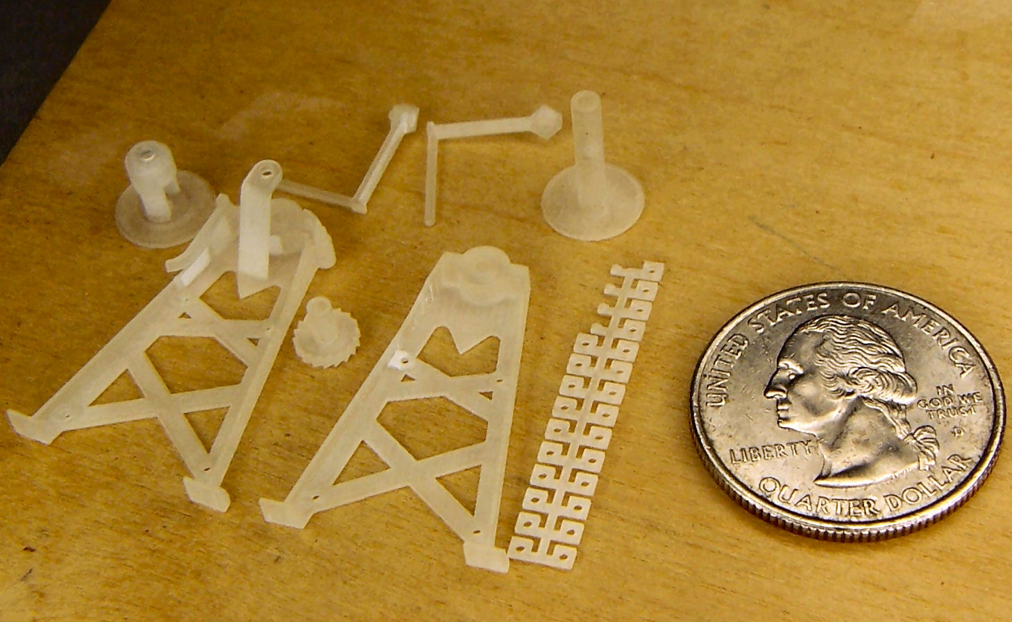
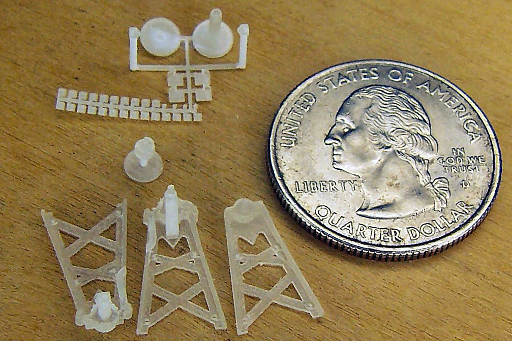
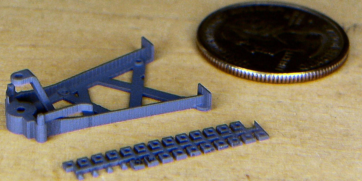
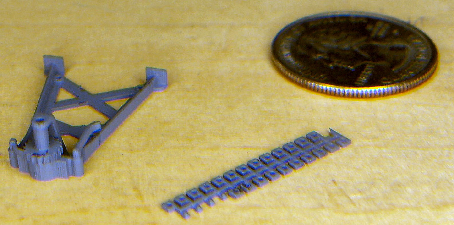
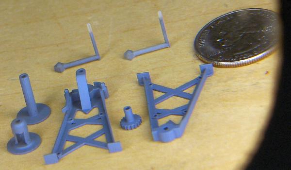
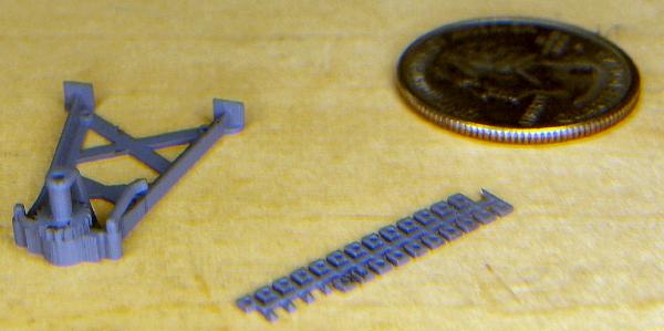
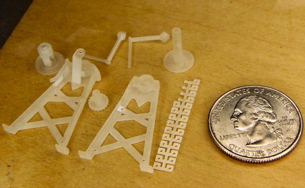
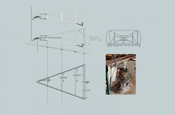
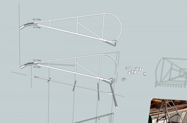
Part 26 The 3D printed parts for the winches came in last week, both the 1/32 and 1/64 sizes. Today I took some pictures. The first couple are the “raw” parts, as they came, and unpainted. I primed the 1/32 scale parts using Badger Stynlrez gray primer, with my airbrush. The primer dries very fast, so fast that I managed to clog the airbrush. I took about ½ hour to clean it, and then I finished painting. The problem is most likely mine. I’m new to airbrushing, and there were a couple other factors. Some time ago I banged the air pressure gauge on my airbrush supply regulator. This is the first time I have used it since then. Yes, the gauge is broken. I had to use the regulator on the compressor, which has courser measurements than the airbrush one. So I’m not sure exactly what pressure I was using. Somewhere between 20 and 30 psi. The airbrush is both a cheap one, and brand new, so I am inexperienced with it. I think I may look into a decent external mix airbrush for priming. Even with a large (.050) needle, it was slow going. The pictures of the primed 1/64th parts will be next week. I have to figure out how to hold these very small parts, without them blowing away. Anyway here are pictures. To take them I had to put my magnifying lamp between the camera and the parts to make them large enough to see in the pictures. The camera was set for close up shots, and I even had to zoom in some, using the telephoto feature. These are the 1/32nd scale parts, with a quarter for comparison. At the left is a part that combines the clutch and the end of the winding drum that the clutch engages. There is a groove to guide the saw so I can separate them. I had to combine them, as the individual parts were too small to be printed separately. Going clockwise, the next two parts are the crank handles, then the other side of the drum. There is a hole through this part for the axle. Strangely, even though I drew a hole in the clutch side flange for the axle, it disappeared when I loaded the file to the 3D printing company checking software. I tried several different ways of putting the hole in, none successful. I finally gave up, but was able to draw a circular depression to use as a guide to drill the rest of the hole out. Next is the sprue with all the nuts on it. Once again the individual parts were too small to print separately. I had to leave the back of the legs flat, the smaller nuts will be attached behind the pawl, and clutch arm, to simulate the other end of the bolt holding them on. Next is the plain leg, this is the one opposite the clutch drum position. If you look closely you can see the four pads that the support rods will bolt through, They are on the back web, along the inside of the vertical webs. Next is the 6” diameter 18 tooth pawl gear. I was pleased to see that the teeth were “pointy” I thought they would print out as blobs I would have to shape by hand. Lastly is the complex leg. This has the pawl gear support, and both the clutch handle, and pawl gear attached. Again the clutch handle and pawl were too small to print as separate parts, and putting them on a sprue left relatively large areas that would have to be shaped, once they were cut from the sprue. So I just had them printed in place, on the leg. The pawl gear fits between the leg bearing and the support arm (See the primed part photos below). Here is the picture of the 1/64th scale parts. It is hard to see details on these, even with magnification and zoom. At the top is the sprue with the smaller parts, the drum halves, crank arms, and the feet for the legs. As I mentioned in a previous post, I had to make the vertical web on the legs thicker to meet the minimum that the company can print. I will sand the web to thickness then attach the feet to the thinner web. If I had printed the feet on the legs, I would have had to leave the webs thick, as the foot detail would have covered some of the area I have to sand. The nut sprue is attached to the rest of the sprue, not separate, as in the larger model. Even with the minimum wall thickness, I was able to have the hole through the larger nuts. I will use it as a guide to drill them to size. I was able to still have the hole through the large drum part. As mentioned below the clutch drum has the “left side axle. The hole in this large section will have a metal stub axle inserted, for the other end. The hole is long enough to allow me to adjust as needed, during assembly. Below these is the clutch drum on its mount. The circular mount makes the whole thing large enough to print. The vertical rod portion will be trimmed and used as the axle on that end. Next at the bottom right is the simple leg. It has a depression on the flat side, to accept the metal axle stub. On the front side the portion of the axle that the crank handle attaches to is printed in place. Even at this small size, the pads for the support rods could be printed. Last are the two parts on the left. These are two complex legs. I have the one turned to show the detail at the top (at least as much as can be seen). Once again the clutch handle, and the pawl are printed on the leg. I had to make them thicker, but did so in a way that allows me to thin them down. After looking at the part, I think I will leave the pawl, as is, and just file the clutch handle. To save a lot of hassle, the pawl gear is also printed in place. I can’t see it well enough to determine how it looks, but I can feel the teeth with my finger nail. I’m quite pleased with the detail that can be done. The other leg shows how the gear, pawl, and handle turned out. Those with good enough eyes, can see some indication of the teeth. As with the first leg there is a hole in the back for the axle, and the crank handle end is printed in place. Here are some shots of the primed 1/32nd scale parts. An overall shot. The ends of the handles were stuck in the foam to hold the parts and did not get painted, nor did the one side that faced the foam get a good coat. You can see that the vertical web gets taller as it approaches the bearing casting at the top. This transition is curved, not just a straight line. This came out in the print. You can also see the support rod pads, better. The gear teeth are “sharp”, as printed, no shaping needed. This one shows the back of the parts, and the top of the complex leg. It shows the crank handles, pawl, and clutch handle better. The support for the pawl gear (arm coming up from web), was printed as part of the leg, in both scales. This is a close up shot of the nuts and complex leg. Here is the pawl gear inserted into place. There is some roughness as you drag your figure nail along the parts, but a little sanding will fix that. I do not think I could fabricate these parts in 1/32nd, it would be pushing my skills to the limit, especially getting the leg webbing to match on all four legs. I know I couldn’t fabricate them in 1/64th! I’m glad that 3D printing is available! There are some modelers out there who could do this, and I applaud them! Next week I’ll prime the smaller winch parts, and post them. After some experimenting, I will be printing out the dredge frames, also. Even in 1/64th, the detail will be good enough, almost scale thicknesses on the frame bars, at this scale. They will look much better than ones I could make by hand. I found some pictures of the dredges, and have adapted details from them. The drawings for the Willie Bennett, simplify the detail somewhat. Every dredge I found differed in detail, so mine should look just fine. This is what I have so far. One major change is the bottom support bar. Rather than being welded in line with the cross pieces at the bottom, it runs along the top, and has a ring and hook arrangement, at the front. I'm not sure what this does, but all the pictures I've seen show a similar set to this. On a side note, at this time someone is selling real oyster dredges on EBAY! If they were not a 10 hour drive away to pick up, and my truck was not acting up, I’d buy one! What a display base/case I could make of one of these for the four boats I’m planning on, as well as other Chesapeake Bay models! The dredges for sale are smaller versions, than those commonly used on the skipjacks, but for my use, that would be better. The plastic material that the parts are printed in, is described as stiff and fragile. I have been playing with the parts, and there is some flex, and they seem quite strong. Not construction grade, but not delicate either. P.S. I had four of each winch printed. I’m glad! While getting the parts ready for painting, one of the crank handles flipped onto the floor, never to be seen again, at least until I step on it, and hear the crunch! All this would be so much easier if I was 40 years younger, and my hands didn't shake.


-
I got a good look at the parts today, nice! The bulb in my magnifying lamp went out, and I had to buy another one today to see the parts. The detail is very good, on the 1/64th scale winch, I can feel the teeth on the 6" dia, 18 tooth gear. I will have to prime them, before I have a hope of getting pictures, they are printed in a frosted clear plastic, that will be hard to see with my camera, until I do. In fact I will have to prime them before I can see the details on the smaller parts myself. I will do that in the next couple of days, I have a busy schedule until Sat. After some drawing, it looks like I will be able to have the dredges themselves printed in 3D, in both scales. I will have to throw away the last 4 or 5 days of drafting, but this is a learning experience. (I always used to hate being told that phrase, but now I'm doing for myself, not others.)
-
The 3D printed winch parts arrived tonight. I'll give more info tomorrow when I get a chance to look at them closely. I need to take the packages out to the shop, before I open them, or the pieces will disappear.
-
Reading Boat Drawings
thibaultron replied to Julie Mo's topic in CAD and 3D Modelling/Drafting Plans with Software
Yes -
Well it looks like I will have to experiment with photo etch for the dredge itself. I drew it up and almost the entire thing has cross sections that are too thin, even in 1/32 scale, let alone 1/64th. It will have to wait until next year. The winch parts should be in Monday. I'll tell you how they turned out.
-
Modelexpo Fair American Rigging issues
thibaultron replied to Ralph Crouse's topic in Masting, rigging and sails
Ships in Scale sells a practicum on this model, " Progressive Scratch Building". It covers a couple other smaller boats too. I boght it several years ago, and read it cover to cover. You can get it on CD. I think someone else also offers a practicum. -
Just got an e-mail from the 3D printing company, the winch parts were successfully printed and in the mail.
-
Received word today that my winch files have passed muster at the 3D printers. They are in the queue for printing. Today I'm starting on the rearranging of the shop to move the HO layout into the new area. My workbench is in a section of the layout supports, so when it is moved, I can start work again.
-
Bolt Heads on Brass Strips
thibaultron replied to mikiek's topic in Metal Work, Soldering and Metal Fittings
One of the model railroad suppliers sells Rivet Detail decals. These are clear film strips with raised rivet heads on the strip. No idea how they do the raised detail, but they look good when used. -
Yea, just go over there and old "Five Finger" willie will teach you about shop safety.
-
While the mast being thickest at deck level, is true for most ships, be careful, on smaller ones at least. The plans for the Chesapeake Bay skipjack (a 30 to 60' sail powered oyster dredger) I am working on, and another in the wings, both are thickest a couple feet above the deck, then start the tapered octagonal shape as they go toward the foot. They are about 1" narrower when they enter the deck. I don't know if there are any others where this happens, it might have been a regional thing.
-
I considered photo-etch, but the round axle bearing areas on the top of the legs would be hard to do in photo-etch in both scales. I don't think I could fabricate them in 1/64th scale, that engine for the push boat was bad enough. The handles for the clutch and pawl, would be really small. Photo-etch would work for the lower portion of the legs, the pawl gear itself, but not the shaft. I also have no idea how the clutch body would be done in photo-etch. I've never used either process. I will see how the 3D printed parts come out, if they do. For parts that can be fabricated as flat parts, and folded (railings, gun tubs, etc.) the photo-etch would work. Look at all the detail sets for the plastic models. There are some very complex kits for HO scale, but building one takes real skill. To solder the joints they use a resistance soldering unit. These run about $500, way over my income level. CA would work for many of our parts that will never be touched again, after being installed, but anything that required handling needs to be soldered. This is really a question for more experienced modelers. My 2 cents worth.
-
Sorry The title is wrong. I'm asking if anyone is interested in a tutorial on converting a 2D drawing to a 3D printed model. I started another thread asking the question.
-
I recently drew up a hand powered dredge winch (about 3' X 3' X 2' in full scale), in a 2D CAD program, then went to a 3D model in SketchUp, then to an acceptable STL file to be printed by Shapeways. Would anyone be interested in a thread on the process, and some of the pitfalls along the way? The winch pushes the limits of their tech, when translated to both 1/32nd and 1/64th scale printed models. The winch is for my Carrie Price Skipjack model, in another build thread, but I thought that this subject would be more suitable for a wider audience.
-
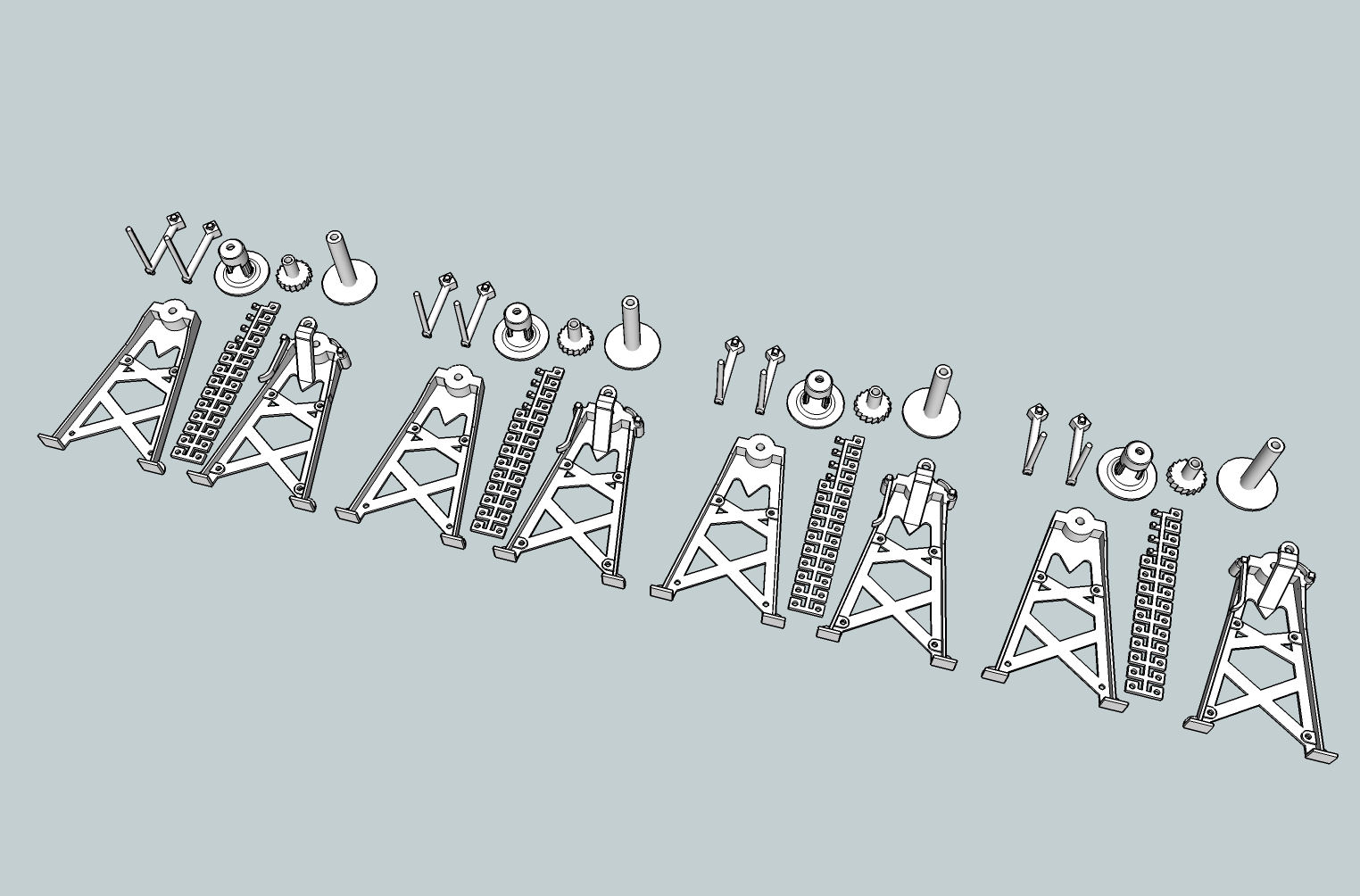
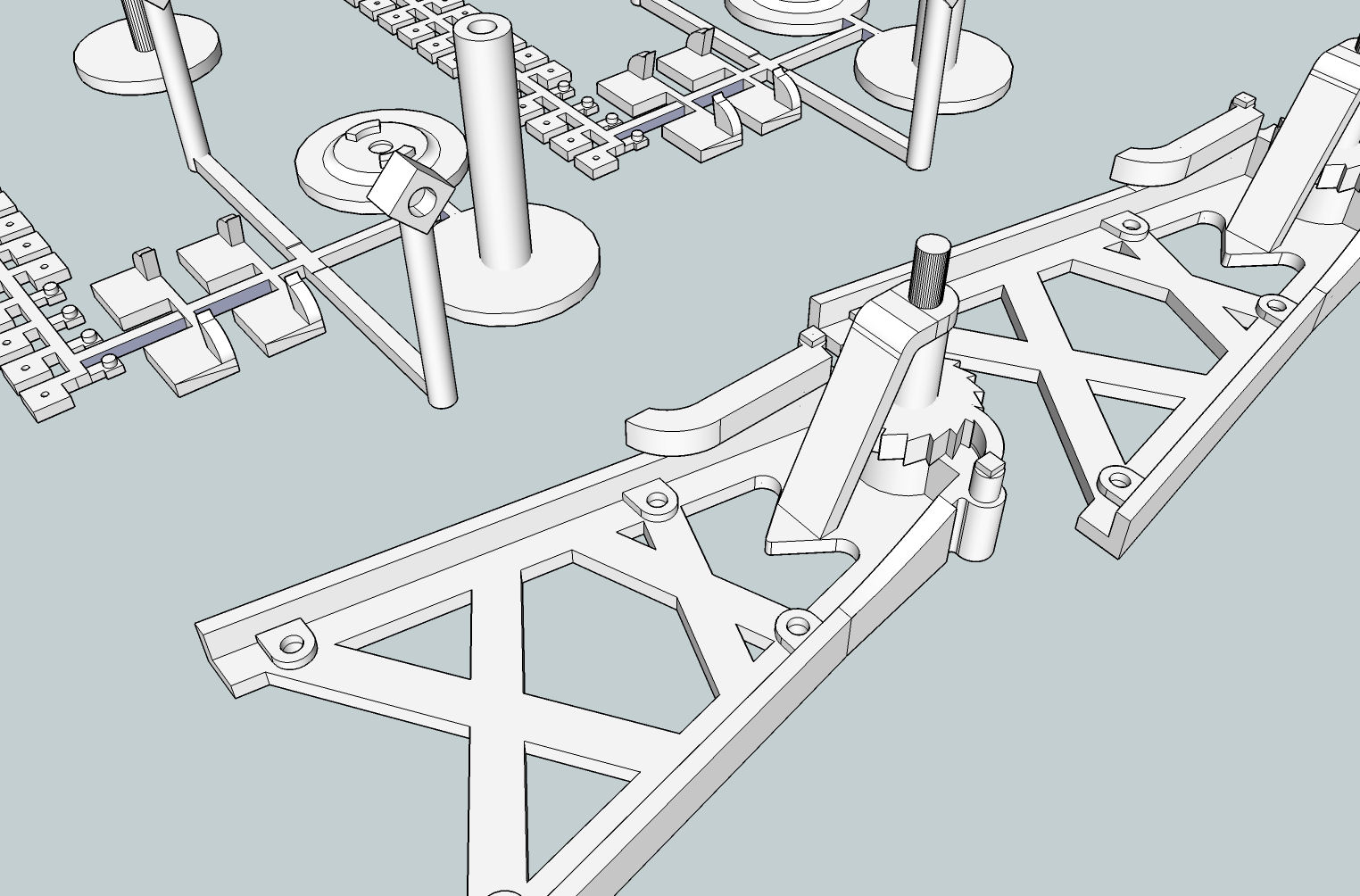
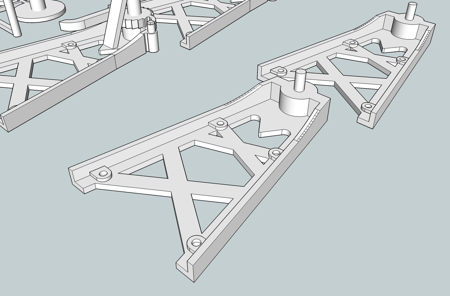
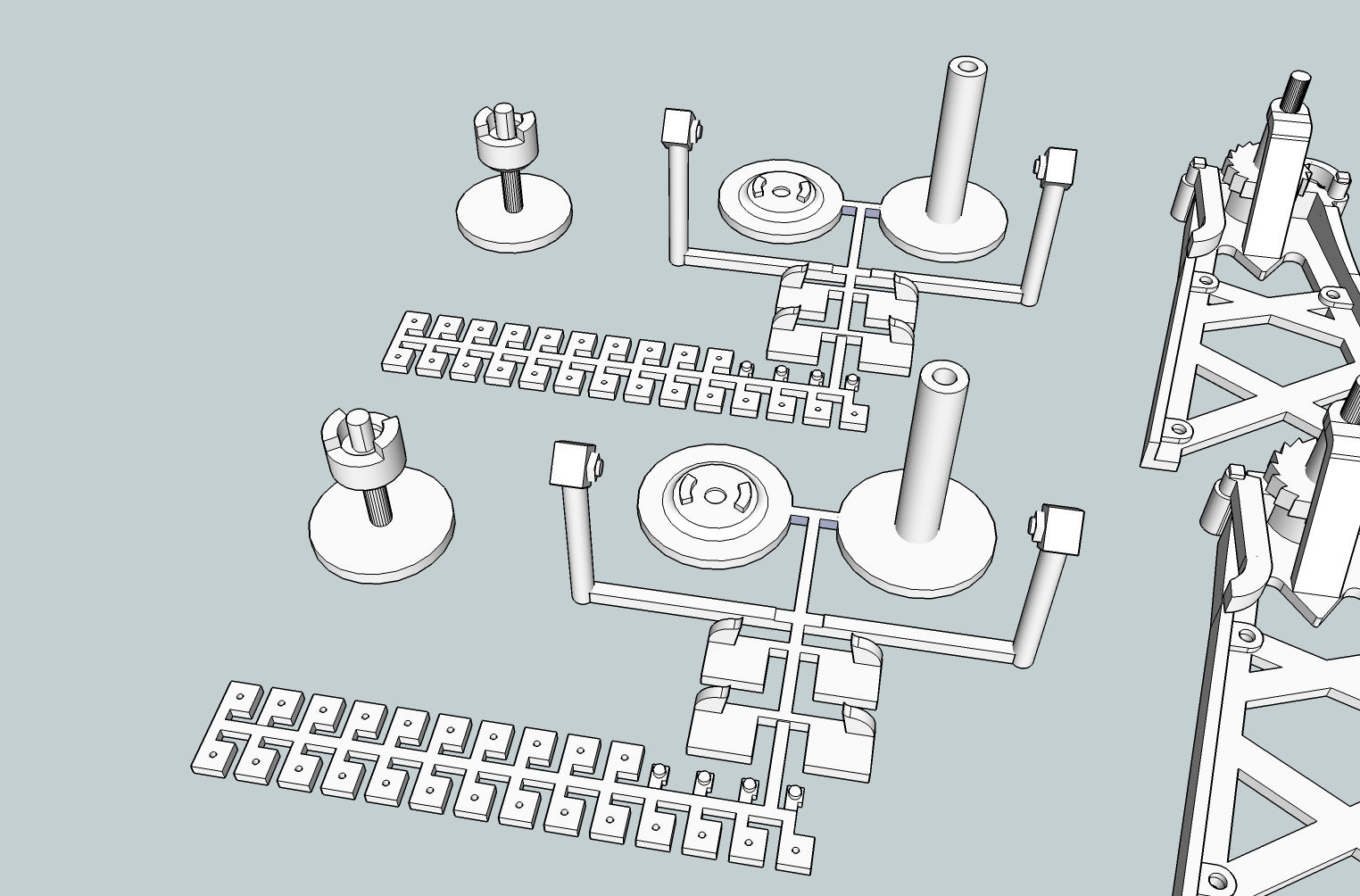
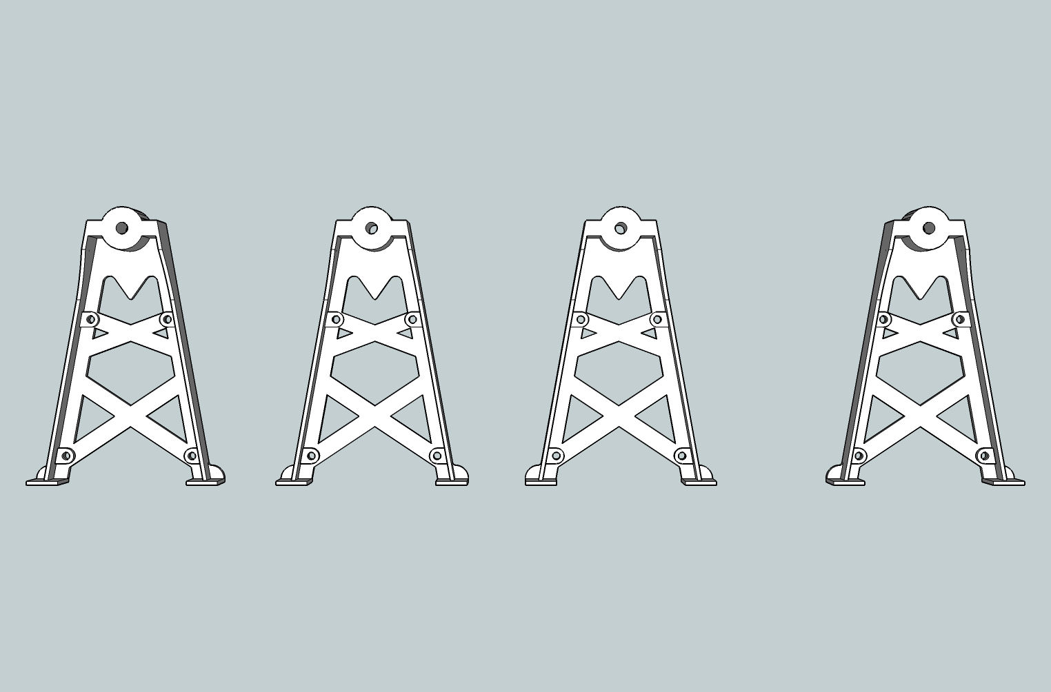
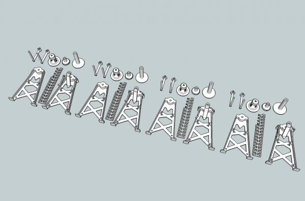
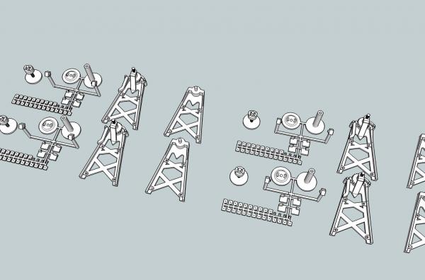
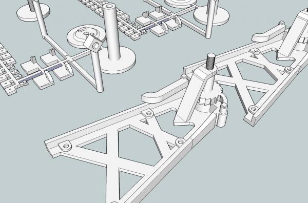
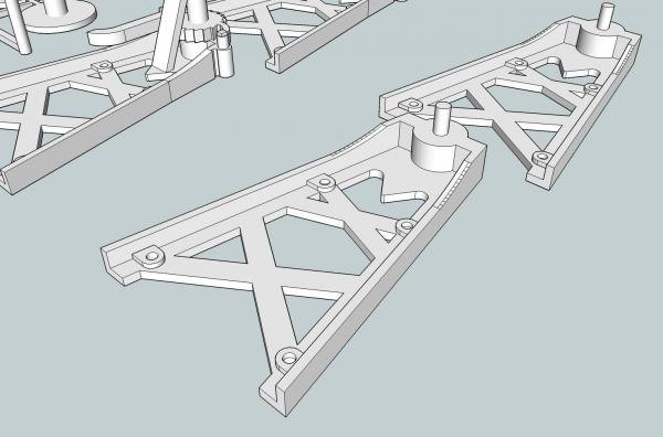
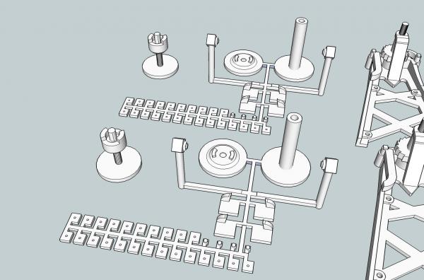
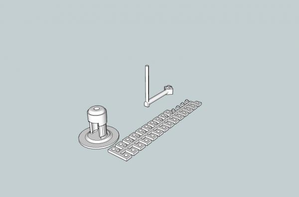
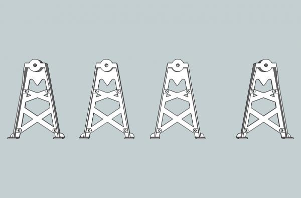
Part 25 I spent the last couple of weeks translating my winch drawing from the 2D CAD drawing to a 3D drawing acceptable for the Shapeways company to print. I choose Shapeways because I have heard about them often on my model railroad forums. There are also other companies that do the 3D printing. I used the Google SketchUp program to create the 3D drawing. This program is available as a free version, with some of the features of the purchased program disabled. The disabled features are not needed to create a drawing for a modeler. I have both an older Pro version, and the latest free version. The only Pro feature I used was the importing of the 2D CAD file. The free version will only import picture format files. You could convert your CAD to one of these formats to use with the free version, or just start from scratch using your drawing for reference. After importing it I switched to the newer free version. The pro version is $700, so you will most likely be using the free one. There were some pitfalls along the way, as the parts had to be drawn in a certain “philosophy”, for lack of a better word. I may be doing another thread on just this process, if I find any interest. The files still have to go through their manual check process. I do not think there will be any problems that will make them unprintable. If there are, they will refund your money, and tell you what has to be corrected. Anyway here are some pictures of the finished drawings. This is the drawing for the 1/32nd parts. There are enough for 4 winches in this one. It only cost a little more than just printing two winches, and allows me to break something while assembling the model. Shapeways charged about $20 total + shipping to print this one. Here I found a mistake after paying for a copy. SketchUp has a feature (one of the free plugins) that checks for problems and corrects them. You have to recheck your drawing after doing this, as sometimes it “corrects” the drawing, by deleting offending parts! This happened when I checked this drawing, and I missed it. Look at the leg at the lower left. The bosses for the support rods are missing at the bottom of the legs. Compare it to the leg on the right. Rather than correct the file and print a new one, I corrected it, and made a new file with just the four corrected legs. This print was about $9, and I got it in soon enough that they will include it with my first order, so I didn’t have additional shipping. Back to the first drawing. The handle for the clutch mechanism, and the pawl were too small to print individually, so I added them to the one leg. They are small and have a lot of curves, so attaching them to a sprue would have left a lot of trimming to do. Likewise the clutch end of the drum, and the clutch were combined (the thing that resembles a hat, above the legs. When I go to assemble the model, I will separate them. I left a “channel” between the drum and clutch parts to aid in guiding the saw. The long “thing” between the legs are the nuts for the model on a sprue. Once again an individual nut was too small to print. Some of the nuts will be attached to the back of the legs, which for printing have flat backs. There is also a foot at the handle to crank arm joint, to support the part during printing. I will sand this off of the finished piece. The 1/32nd model is designed to have an axle to string the drum, clutch, pawl gear, and crank handles. The supports and axle will be metal rods. The leg webs on the 32nd model are about scale ½” for the “walls” and back. This is close to the minimum requirements for printing (.3mm). The 1/64th scale version had to have some major modifications done, to satisfy the minimum thicknesses that could be printed (.3mm). The leg webs had to be thickened. For the plain leg this was not a problem, I just made them thicker. I will sand the back and straight sides to thin them closer to scale. Notice that the axle, is cast in place for the handle. There is a hole in the back for the clutch and drum assembly. Both legs are setup this way. The pawl gear end leg presented some problems. The top of the leg has bosses for the pawl and clutch handle. Thickening the whole length would have destroyed the leg to boss transition curves. At this transition area, though, the scale leg was already thick enough. I therefore only thinned the lower straight section of the leg, and will sand this straight section to thin and blend it. The web at the back of the leg also had to be thickened to about 0.9” in scale. It is flat on the back, so sanding it down to ½” scale will not present a problem. Once again the final print is four winches, to allow for mistakes. Unfortunately the pawl and clutch handle had to be significantly thickened.. For the pawl I will just leave it as is. For the handle I thickened it on the inside so that it will be somewhat easier to thin it, and errors will be better hidden. Trying to use a metal axle for this scale was an unreasonable (for my skill level) fiddly idea. So for this leg I inserted the pawl gear into the assembly. The clutch is now on its own base. Trying to cut it from the drum would have been tricky, and now the axle is cast as part of it. The drum end has a hole for the axle to fit in, and the back has a recess for the drum shaft. The shaft end of the drum is hollow. Here I will use a short piece of metal for the axle, but I will have that long hole to allow for adjusting the rod. For both legs I made the little decoration at the foot separate parts. They will be attached after the leg webs have been sanded (he says confidently. Hope springs eternal). I was able to also print the nuts, but had to use a much smaller hole. I will drill these out to scale, using that hole as a guide. The supports will be metal, but simply string through everything Here are the small parts on their sprue. The handle for the cranks are square at the end, for printing. I will round them off. The clutch axle is overly long, and will be trimmed to fit. On both models I have a surplus of nuts, as I’m sure some of them will disappear or be damaged during assembly. This file cost about $8 + shipping from them. Shapeways still has to do the manual checks, which I should get a, hopefully, OK this week, and they will be print sometime in the following week. I just hope my building skills are up to the 1/64th winch assembly. The plastic that these will be printed in is somewhat brittle, but the only one with fine enough detail to do the job. I would have to significantly thicken everything to use a different plastic, and the 1/64th parts would not be printable at all. If there is interest I will make these available publicly from Shapeways.
-
I recently drew up a hand powered dredge winch (about 3' X 3' X 2' in full scale), in a 2D CAD program, then went to a 3D model in SketchUp, then to an acceptable STL file to be printed by Shapeways. Would anyone be interested in a thread on the process, and some of the pitfalls along the way? The winch pushes the limits of their tech, when translated to both 1/32nd and 1/64th scale printed models. The winch is for my Carrie Price Skipjack model, in another build thread, but I thought that this subject would be more suitable for a wider audience.
- 1 reply
-
- 2
-
-
Belt/disk sander, followed closely by a drill press.
-
Well. Back to the drawing board, literally! Shapeways minimum thickness is .012". This translates to 3/4+" in 1/64th scale. Many of my wall thicknesses are 1/2", for a true scale part (and this is thicker than I think it would be in real life, more like 1/4 to 3/8 thick webs). At least I have practice. I can probably use the existing drawing for the larger scales.