thibaultron
-
Posts
2,944 -
Joined
-
Last visited
Content Type
Profiles
Forums
Gallery
Events
Everything posted by thibaultron
-
 In the UK, I think it is called drywall.
 -
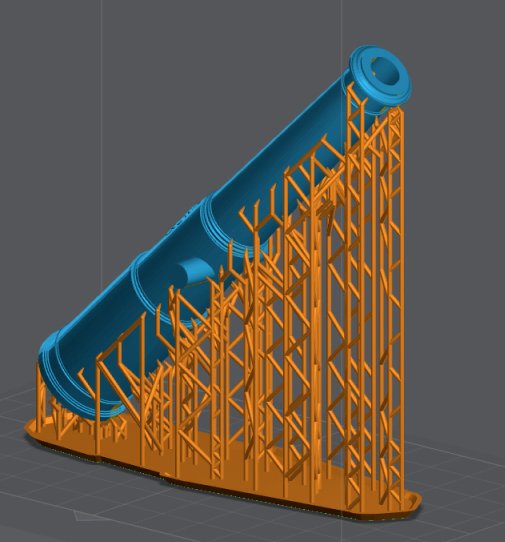
Can you show us a graphic of the supported model, the one with the supports that you sent to the printer (like the example for a cannon below)? We may be able to help you with how they are placed.
-
If the wiring in the boat has a problem, then you are right back at the start. That is why I am recommending assembling the equipment outside the boat to begin with. I think the receiver only needs 6 volts. You can wire up a cheap battery pack to run it during testing.
-
kit review V8 Engine BUILD REVIEW (TECHING) - EngineDIY
thibaultron replied to James H's topic in Non ship-related reviews
James: If there are any plastic parts in one of these kits (present and previous), please do not use that type of oil. It can attack the plastic parts, over time! Use an oil designed for the model railroad hobby. These are plastic safe. Labelle makes oils and grease for the plastic loco parts. Four valves per cylinder has been quite common for automotive engines, for a long time. Gives better flow, for the new pollution standards, and more power for the engine. -
No, setup the new TX/RX, with one new servo, outside the boat, and test it that way, first, to insure it works that way. Then hook up the ESC. Once everything works outside the boat, start putting them in the boat one component at a time. If the system fails when the one is installed, check the wiring for that part.
-
buy a cheap servo to start testing with.
-
DKM U-Boat Conning Tower by yvesvidal - Border - 1/35
thibaultron replied to yvesvidal's topic in REVIEWS: Model kits
Ordered my kit. It has a long lead time end of July to end of August. Ordered the Torpedo loading crew figures also. Shorter lead time, about 2 weeks.- 6 replies
-
- 3
-

-
- U-boat
- Type VII Submarine
- (and 1 more)
-
About 35 years ago I attended my first Nationals with the RC Warship Combat Club (we had radio controlled warships with radio controlled BB guns on them and each team tried to sink the other side's ships). Well we were on one of the reflecting ponds at a former Worlds Fair site. There was a nearby building with a glass outside elevator. Very time the elevator moved my steering servo gliched, and I lost control until the elevator stopped!. Not a good thing! That night the boat worked perfectly at the hotel. In desperation it took a 3 foot long twisted shielded pair cable I had in my tool box and replaced the servo wiring with that. I left the whole thing coiled up in the hull. The next day the ship worked perfectly! I left it that way all week. I took it out and reinstalled the old wiring when I got home, and the boat worked perfectly for the next two years. The combat is not as destructive as it sounds. All the electronics were in watertight and BB proof boxes, and the plywood ribs withstood the abuse. The only thing we had to do was periodically replace the silkspan covered 1/32nd balsa skin. Generally once or twice a year, if I attended every event I could (one week long Nationals, and 4 or 5 weekend long events). We also had mesh armor on the inside of the ribs to protect the equipment, but still allow water to come in through the holes. There was also one bilge pump, that had a restricted outlet. As long as it kept up, the boat stayed above the water. We did this in shallow water, so we could retrieved sunken, or out of control models. I participated for 15 years, and no one ever lost a model.
-
When it arrives, start by just hooking the receiver and one new servo out of the boat, and see if that is stable. Then take the servos out of the boat, and add them one at a time. If everything is OK, hook up the ESC, without the motors attached, etc. Once everything works out of the boat, recheck all your wiring, and start putting the equipment back in the boat, one item at a time. If something fails during this, look at the last thing you hooked up.
-
Chairs! Let’s see your chairs.
thibaultron replied to Desertanimal's topic in Modeling tools and Workshop Equipment
Not in my workshop, but at my computer. I broke one hip 25 years ago, and had the other replaced two years ago. Sitting in any desk chair was very painful for my legs after a half hour or so, and I would have to get up and sit in my recliner, or lay down. Any chair with a regular cushion had the same effect. I saw a review of a chair like this one and bought one to try out. I can sit for hours at the computer now! I spend a lot of time at my computer, drafting various things for my models, so this chair has been great. https://www.staples.com/union-scale-flexfit-hyken-ergonomic-mesh-swivel-task-chair-black-un59460/product_990119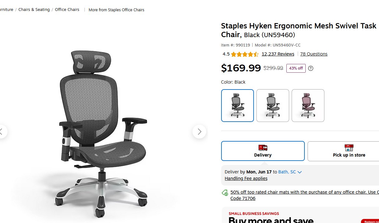
-
disconnect the motor controllers.
-
Redoing Oseberg
thibaultron replied to KrisWood's topic in CAD and 3D Modelling/Drafting Plans with Software
-
Before you give up, take the boat to a hobby shop and ask them for help. Most of them have at least one RC Airplane guy, that may be able to help you.
-
Model Expos sells the plans for the Willie Bennett kit seperately. They frequently have discounts for the plans sets. There are also some pictures in my stalled, but soon to be revived Pyro Oydter boat thread As well as drawing details in my thread on going from a 2D to 3D tutorial.
-
Fine Scale Modeler just published a Figure Painting special Issue. It has been about a month, but it may still be available.
-
If the sword in the original model above, is the one used in his monument, why not offer both? Someone might like to display the monument version next to the ship, rather than a figure on the deck.
-
Atlas craftsman lathe
thibaultron replied to kgstakes's topic in Modeling tools and Workshop Equipment
I second the link belt recommendation! I used them on my 12" Atlas, and they made a huge difference. -
Atlas craftsman lathe
thibaultron replied to kgstakes's topic in Modeling tools and Workshop Equipment
This is an Atlas 6" lathe. You can get "Lathe Operations" by the Atlas Lathe Company, from various places, do a goggle search. There is also a book by Southben, "How to Run a Lathe". Both are excellent books on teaching how to run a lathe. They are both for the larger 10 or 12" Atlas and 9" Southbend, but the same principles apply. The Mr. Pete videos recommended above are also great. Atlas is still in business, sort of. They bought Clausing Machine tools, and use the Clausing name. They don't make the Atlas lathes, or parts for them any more, the Atlas line was dropped in the 70s, or early 80s. -
The forum software, limits the pictures to 1600X1200 pixels. If the picture is, for example, 800X1201, it will not load properly. Also I believe the only file format it accepts is .JPG.
-
Most graphics programs allow you to scale a print in the X and Y axis. As long as you know a dimension in each axis, you can correct the print. Place marks in each axis a known distance apart in your drawing. Then print it at 100%, and check the finished print. If the dimensions are off, use the scaling to correct, and make a final print.
-
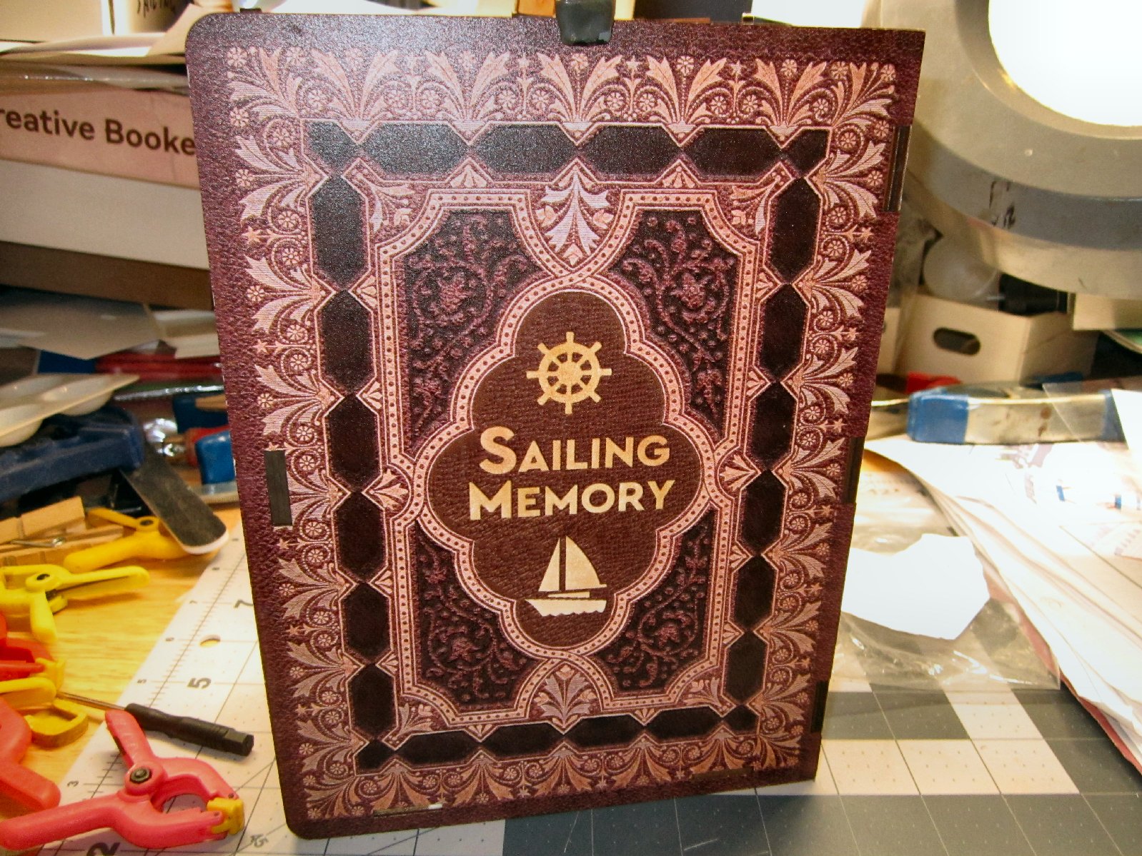
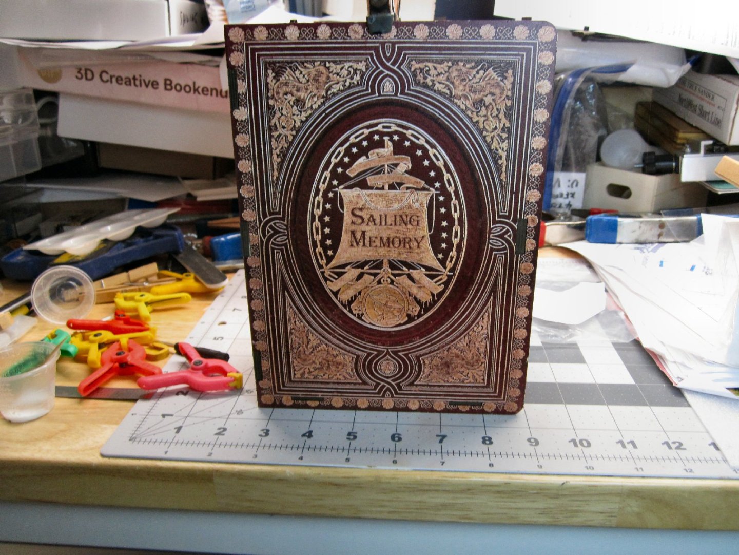
"Sailing Memory" by thibaultron - Book Size Diorama
thibaultron replied to thibaultron's topic in Non-ship/categorised builds
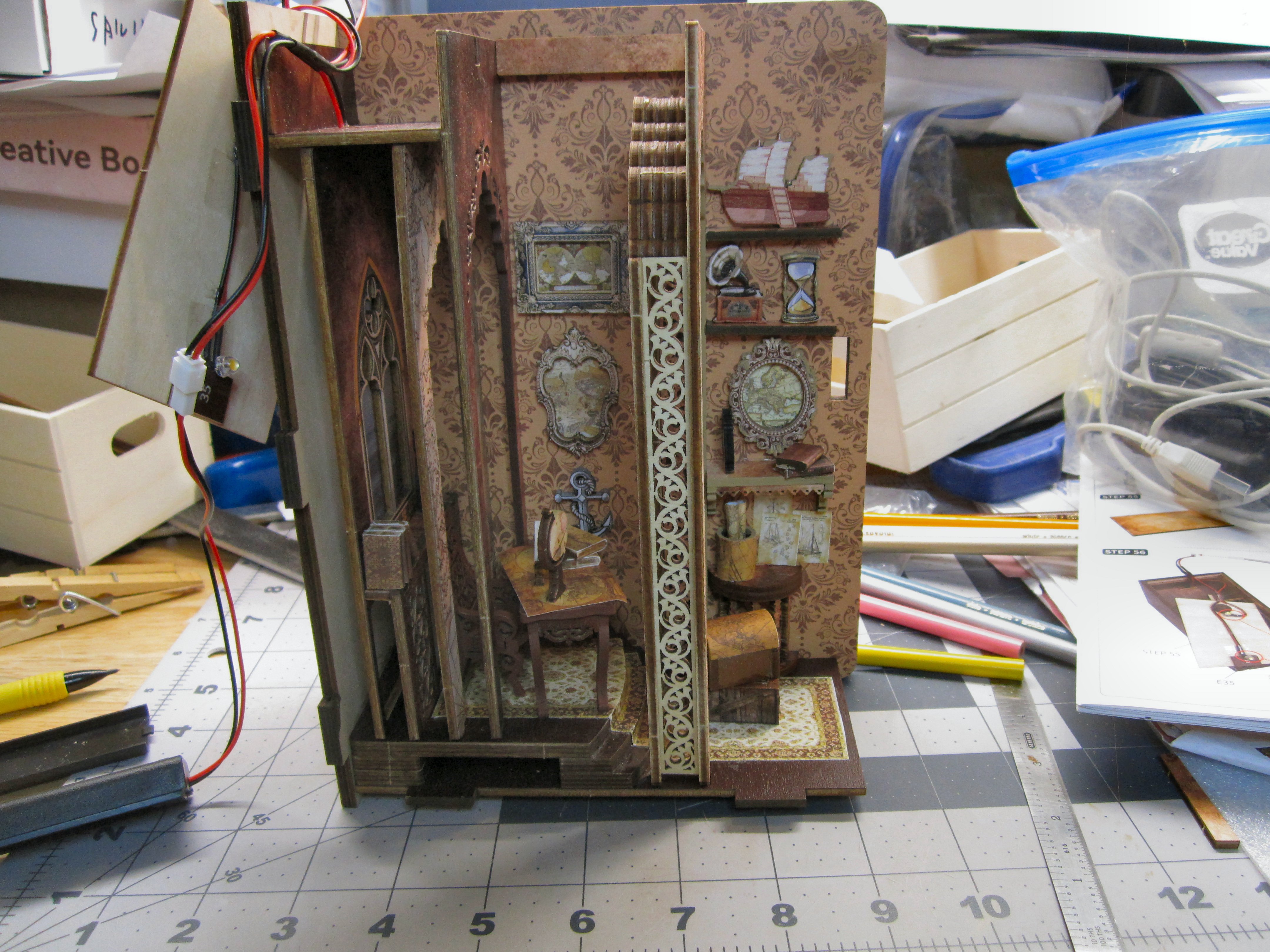
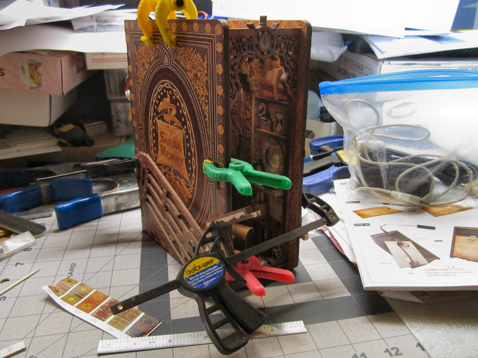
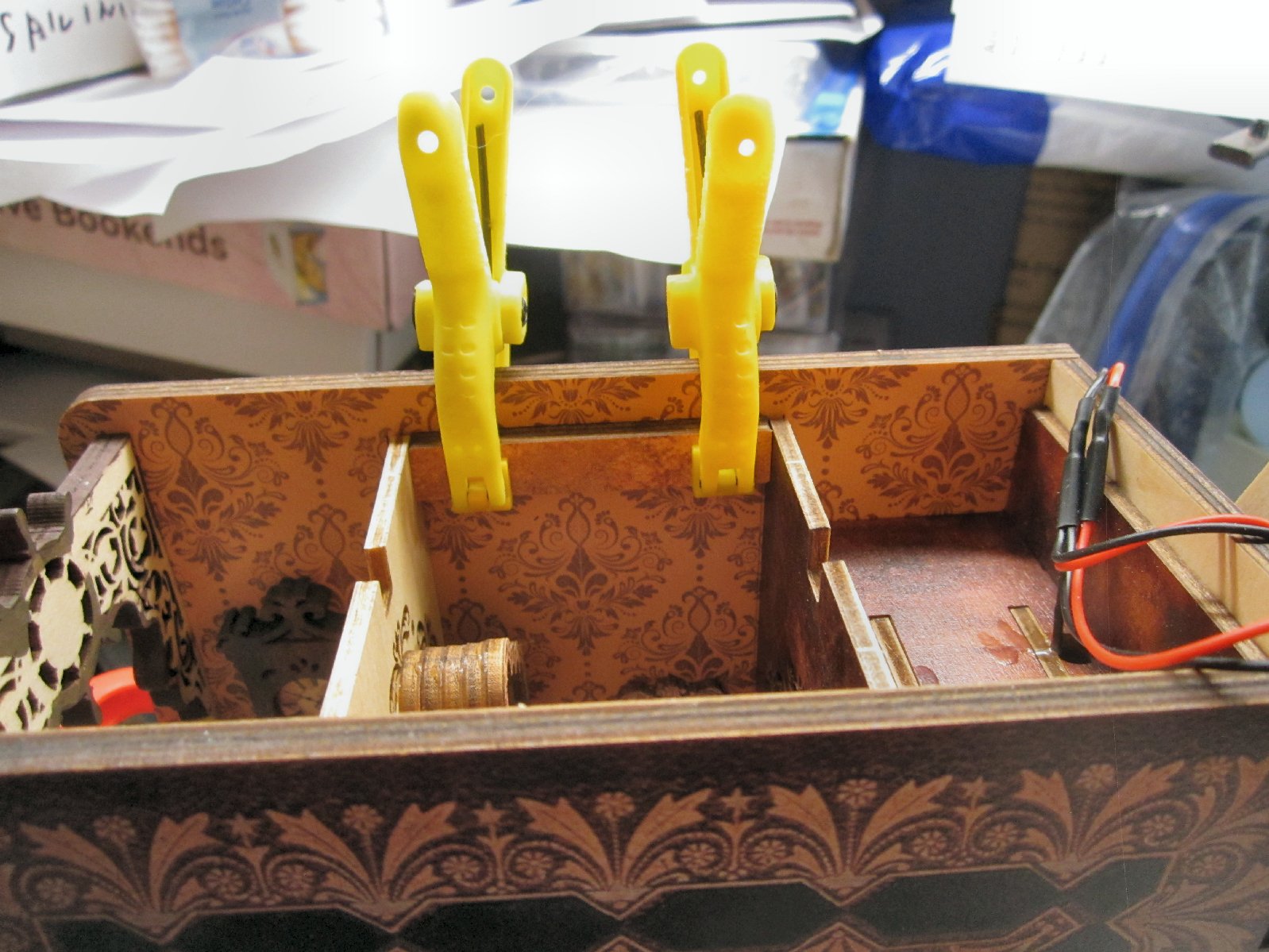
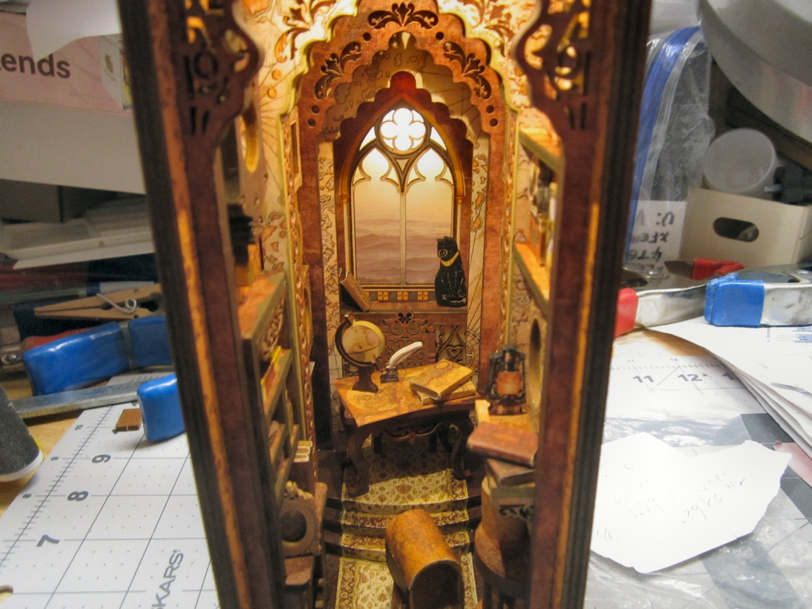
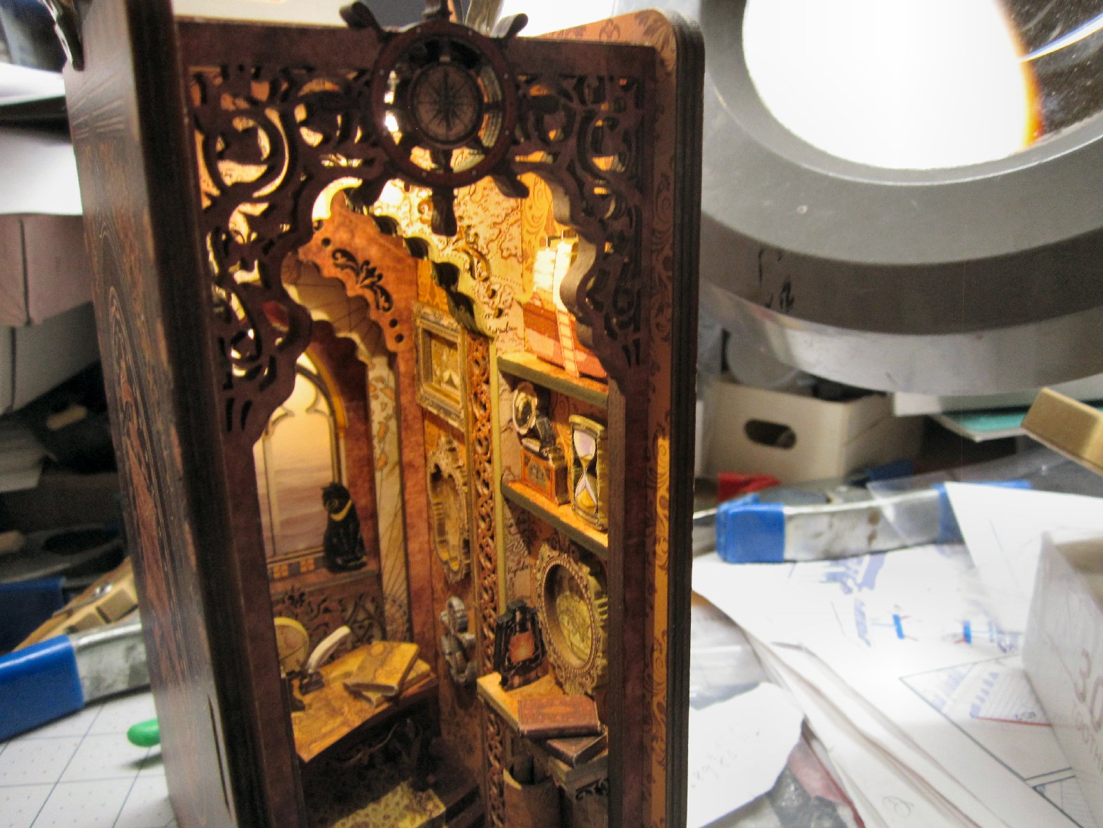
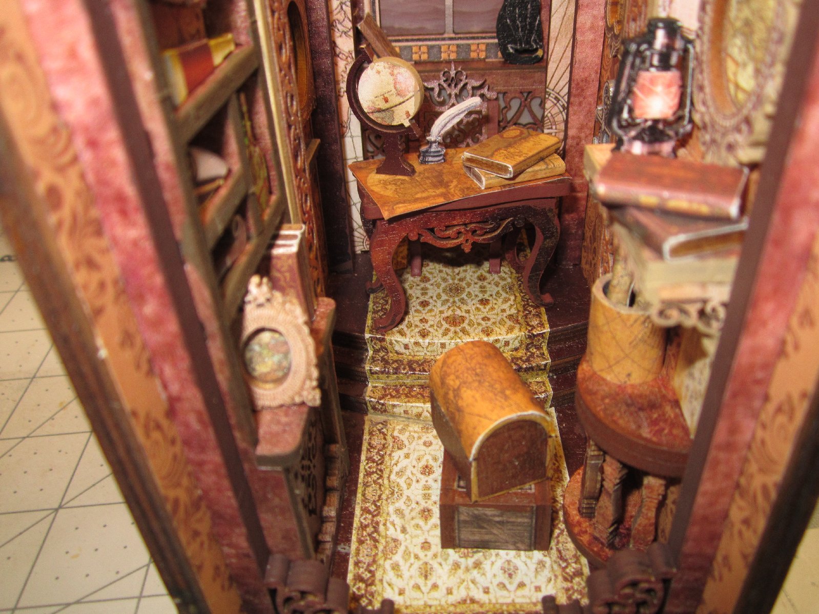
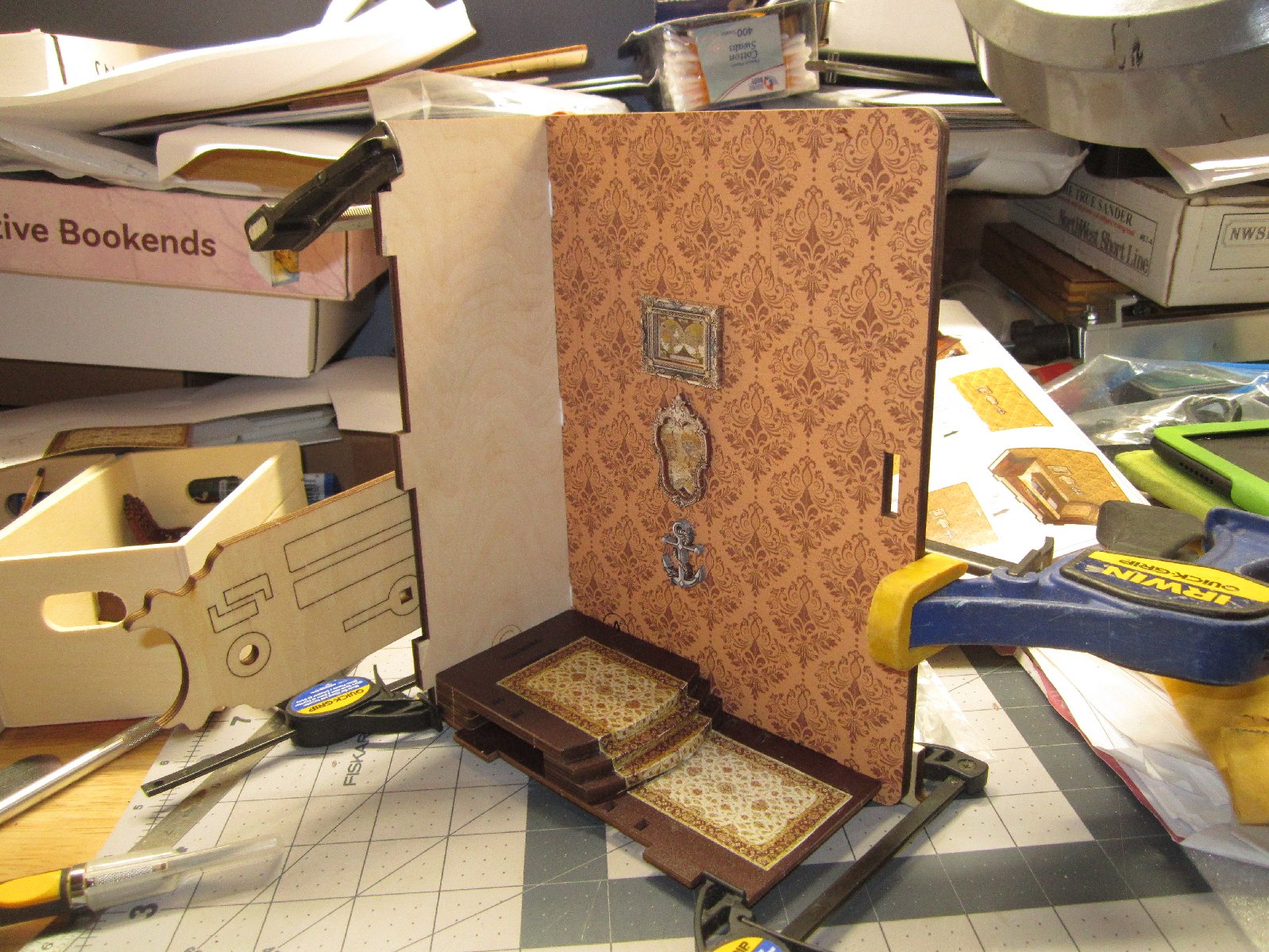
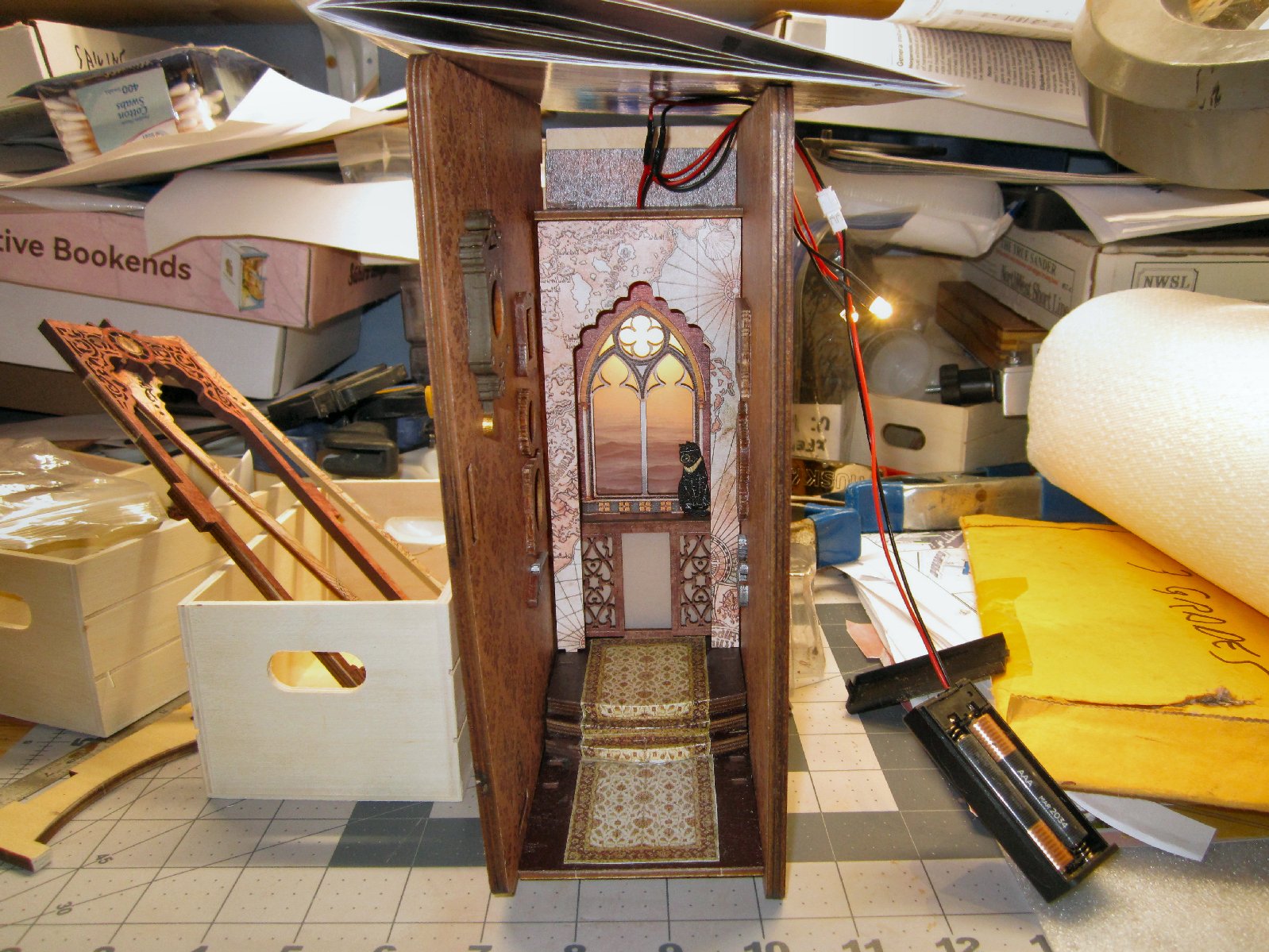
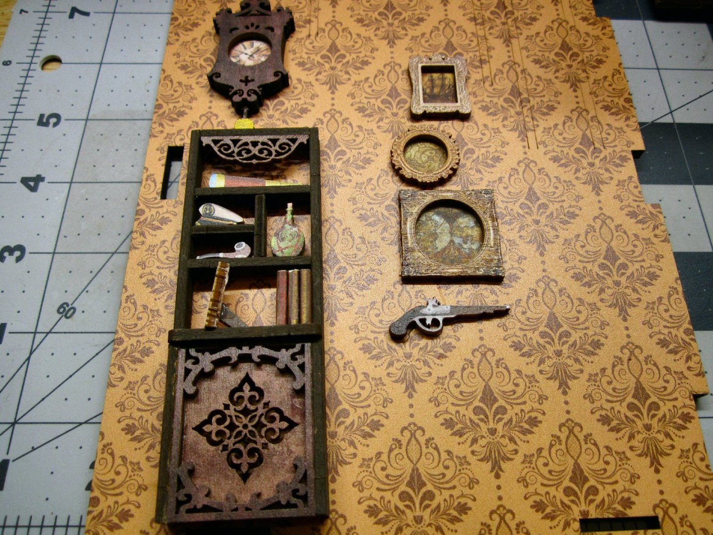
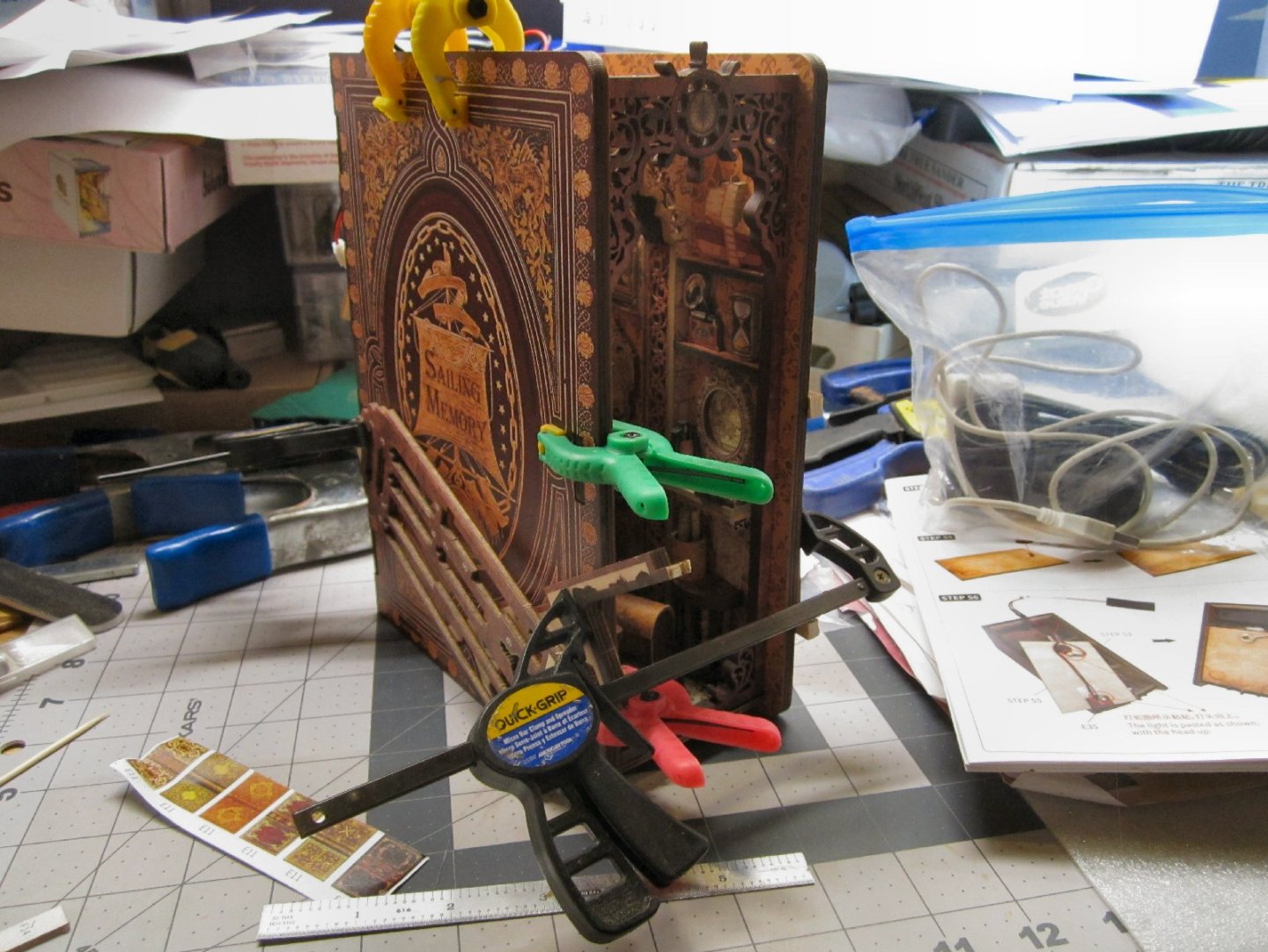
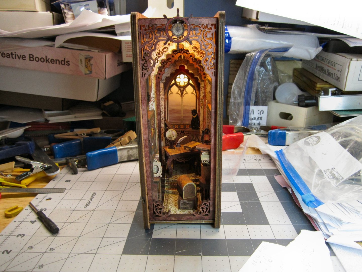
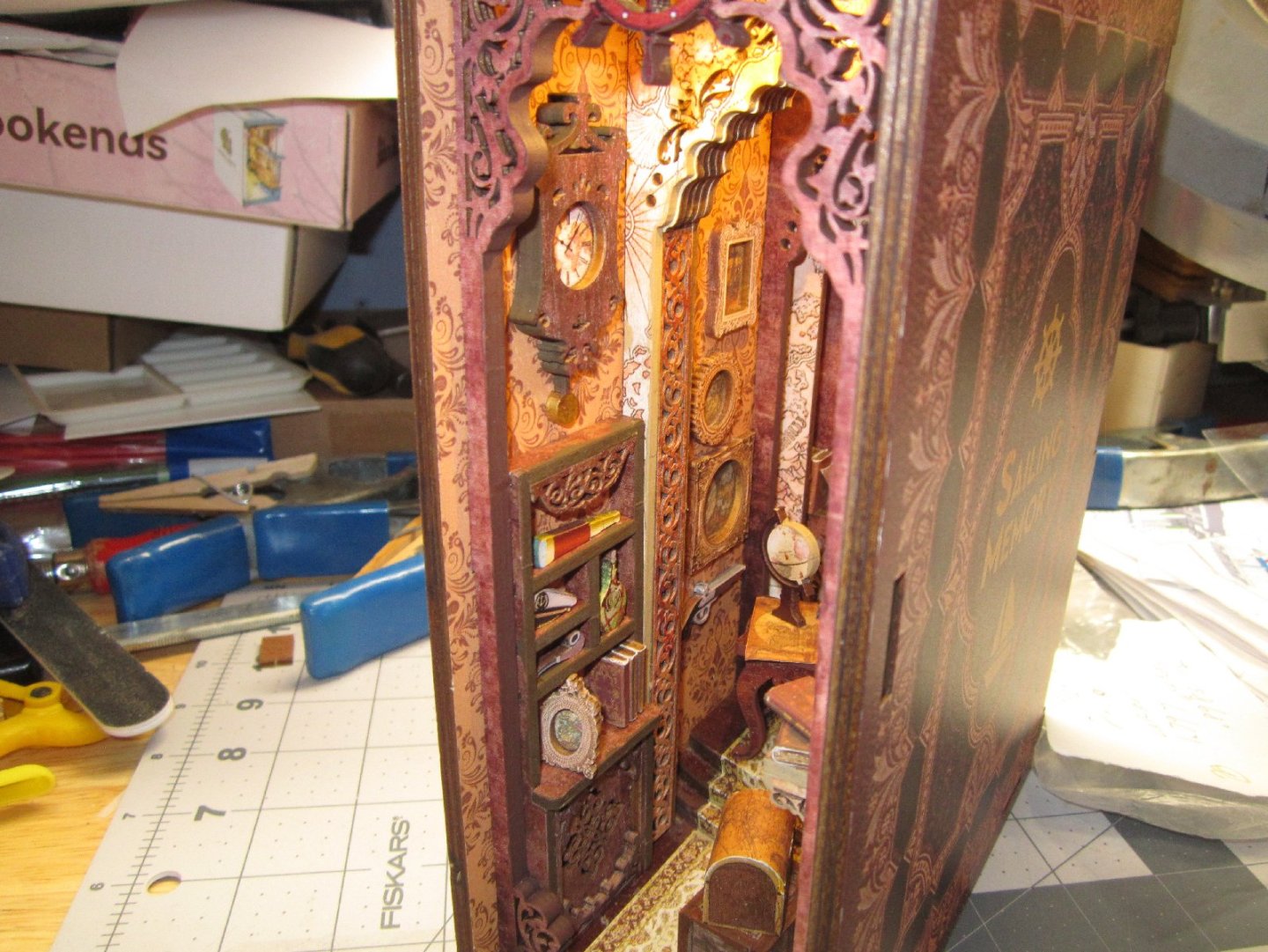
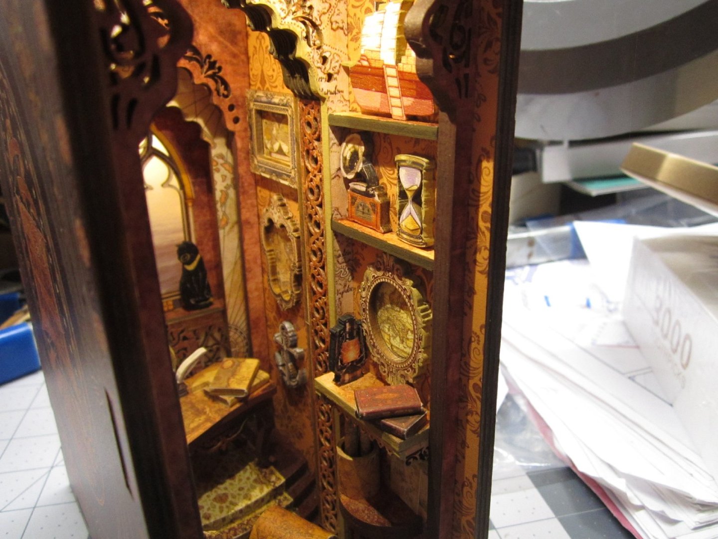
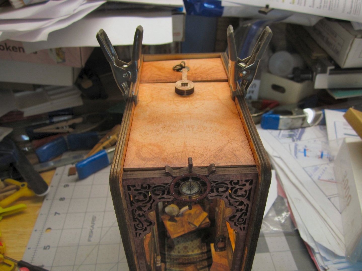
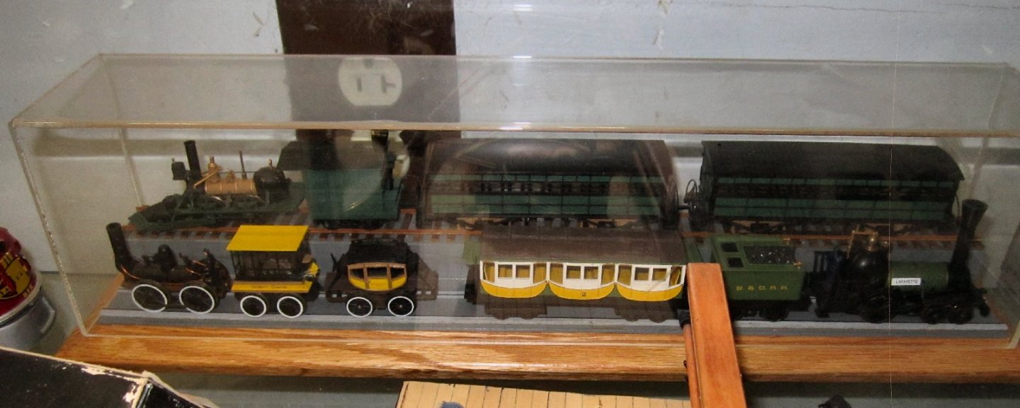
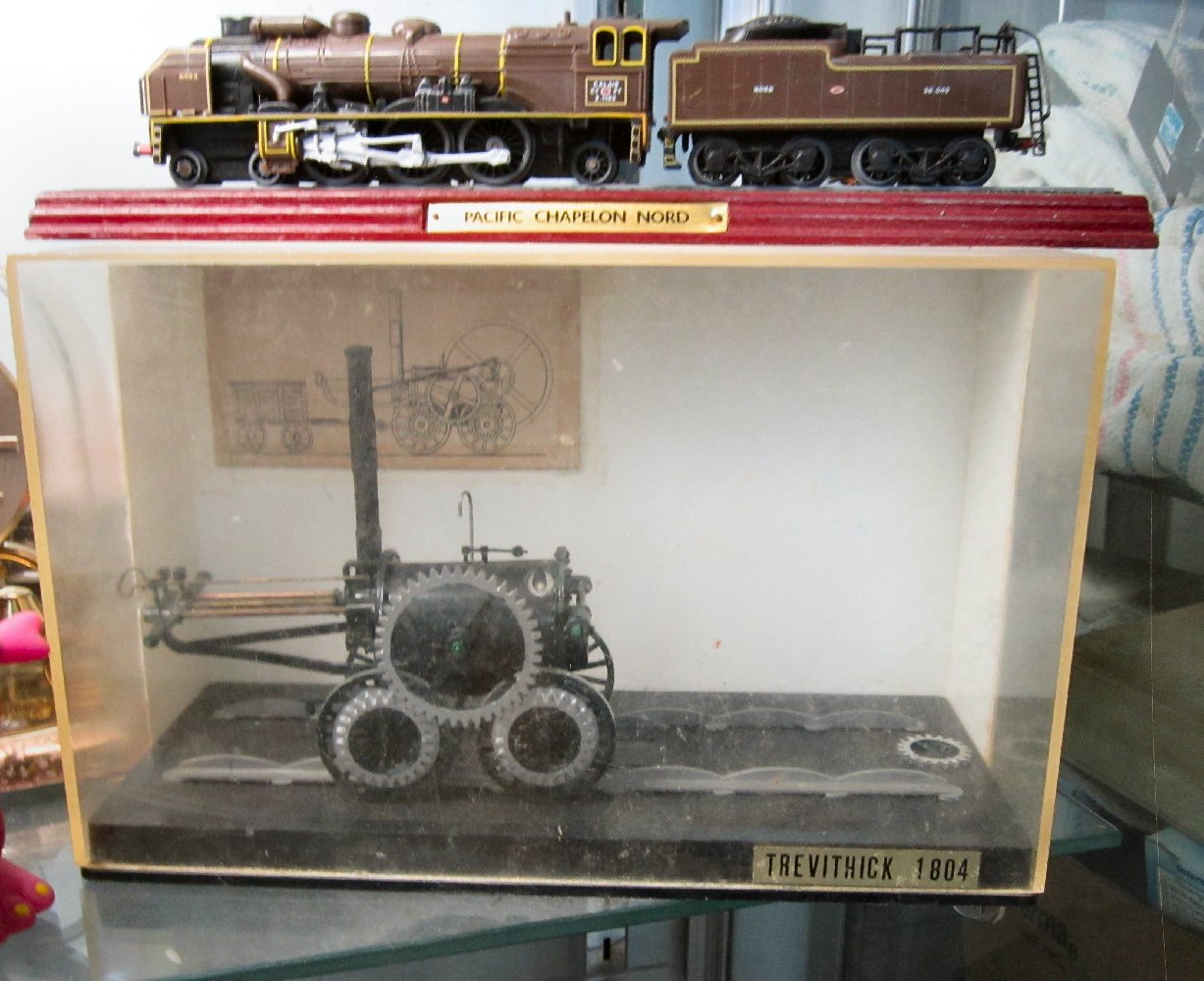
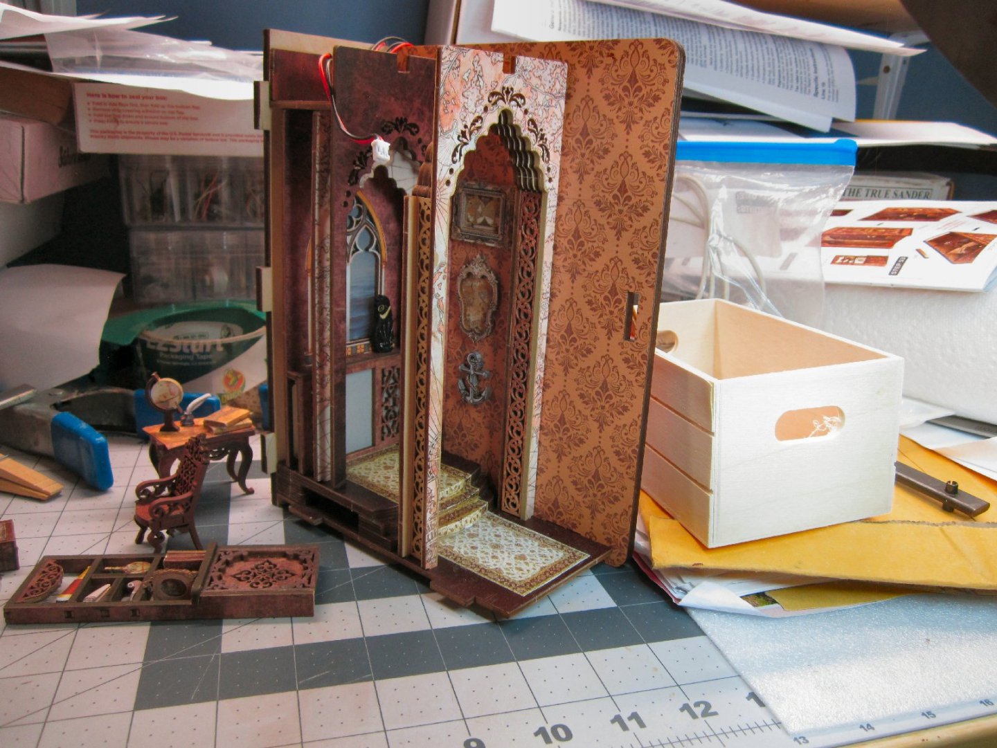
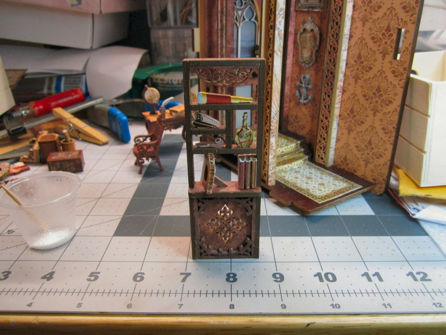
Sailing Memories Part 007 This is the completed right-hand wall of the model. The shelves have been added, and populated. The chest and crate are glued to the floor, and the table with the map holder installed. The last items are three drawings tacked to the wall over the table. You can also see the books added to the cabinet at the back of the display. This is the left-hand wall, before installation. Unlike I thought, the clock is indeed at the forefront of the diorama. I’m glad I took a little extra effort in painting it. The shelving unit is not glued in yet, I set it in the approximate location it will go. I glued it in after this wall was glued on. It fit tightly between the front panel and the foremost arch. I installed the front plate and left wall, clamping it while the glue set. This wall was even more warped than the other, and while all the lefthand sides of the arches were pulled down tight to the floor, the whole unit is slightly racked and the base is a bit wobblily. I may in the future use a piece of sand paper tapped to the workbench to sand the base flat. I glued the ceiling support onto the left wall, and used a ruler laid on the tops of the arches to insure it lined up with them. I glued the ceiling in place, with the battery door installed to make sure everything fit up top. Here are pictures of the finished diorama, with the LEDs turned on. This picture was taken while the clamps were holding the ceiling down, until the glue dried. You can see how the warped walls have slightly racked the top. This will not be noticeable when on a shelf, at eye level. The battery cover at the back, was also sitting on a wire, and fit better when I fixed that. Here is a close up of the floor area. I like this one the best of the three I’ve done, even if it was the easiest to build. There is a lot of detail packed into the “room”. Taking time to paint, or color the raw edges really paid off for this model. This will be the last Book Nook kit for a while, I’m going to turn to some railroad and Maritime models for a bit. I had started on a 1/26th scale Airfix model of Stephenson’s Rocket a while back, but managed to damage it. I have another kit and want to finish that one. I have a companion piece to go with it. It is a static model of the Rocket and one of the original carriages used during its’ winning competition in 1829. The model is in 1/76th scale (British OO) mounted in a display case. I already have a display case with three similar era American locomotive, and their cars, in HO scale. Those three are powered and can be run on a layout. For the train on the upper track, I cut and dyed HO scale crossties from basswood strips, and glued N scale rail to them. The lower trains are sitting on wood rails with painted on iron strap tops. This was the first type of rail used by the B&O Railroad in the 1830s. This type of rail was quite dangerous, as the iron strapping had a tendency to work harden, break loose from the wood portion, and curl up piercing the floors of the cars! Not a good thing, especially if it happed to be a passenger car! To save vertical space, and not block the view of the train on the upper level, I omitted the granite cross ties they used then. If you walk along the present right of way between Baltimore and Ellicott City, you can still find some of these stone ties discarded at the bottom of the fill, and others used to make small culverts under the present tracks. The car(s) attached to each loco are the type they actually pulled. These trains were put out by Bachmann several years ago. If I’m not mistaken, they all served on the B&O. I know that at least the upper one was, as the B&O museum has a working replica that the B&O built for a celebration of the Railroad it held, I think in 1900. I hope it survived the collapse of the roundhouse roof a couple of decades ago, caused by a large amount of snow that built up on it during a major storm. Also, when I was about 12, I got a kit of the Trevithik locomotive that came with a three-piece display case. I’ve had that loco ever since, and carefully packed it with each move I made. About 7 years ago, we had a couple renting a room from us, and while we were on vacation their 4-year-old got into it and the tender disappeared, as well as having one of the gears broken off! I have acquired another model of this loco (one without the case), and want to build it (with a better paint job), and reuse this case for it. The loco sitting on the case is a French Pacific type locomotive, also static. In the upper right corner, you can see a striped rag blanket (made from strips of old clothes ripped into strips that were then rolled and then used on a loom, using them as the left to right “Thread”.) that was made by my Great-Grandmother. Sometime around the turn of the last century.


-
"Sailing Memory" by thibaultron - Book Size Diorama
thibaultron replied to thibaultron's topic in Non-ship/categorised builds
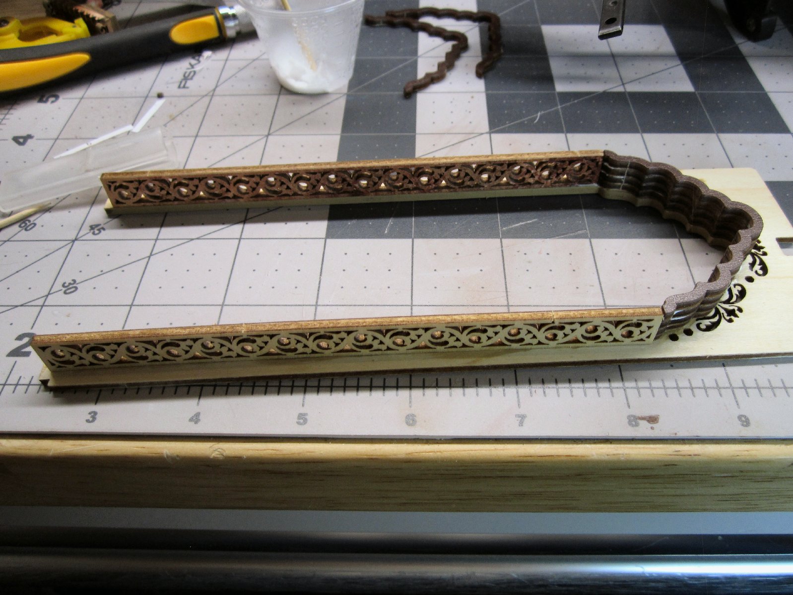
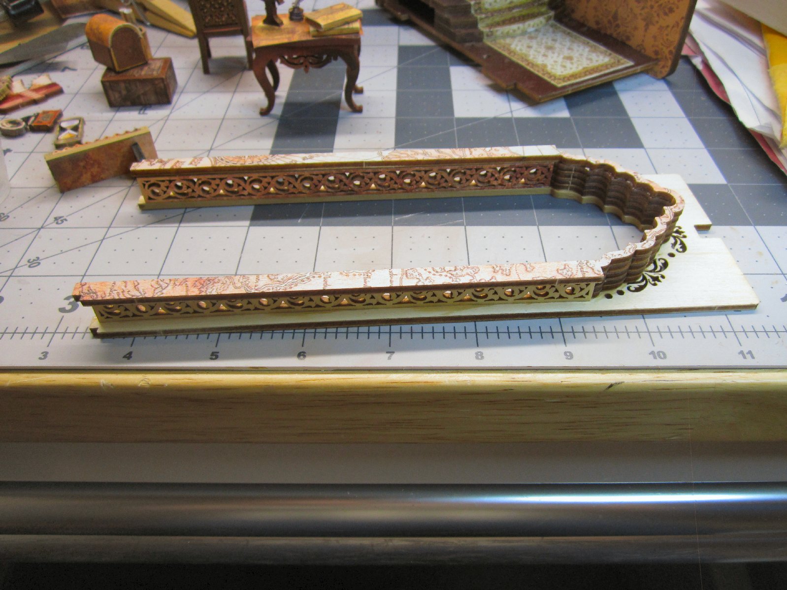
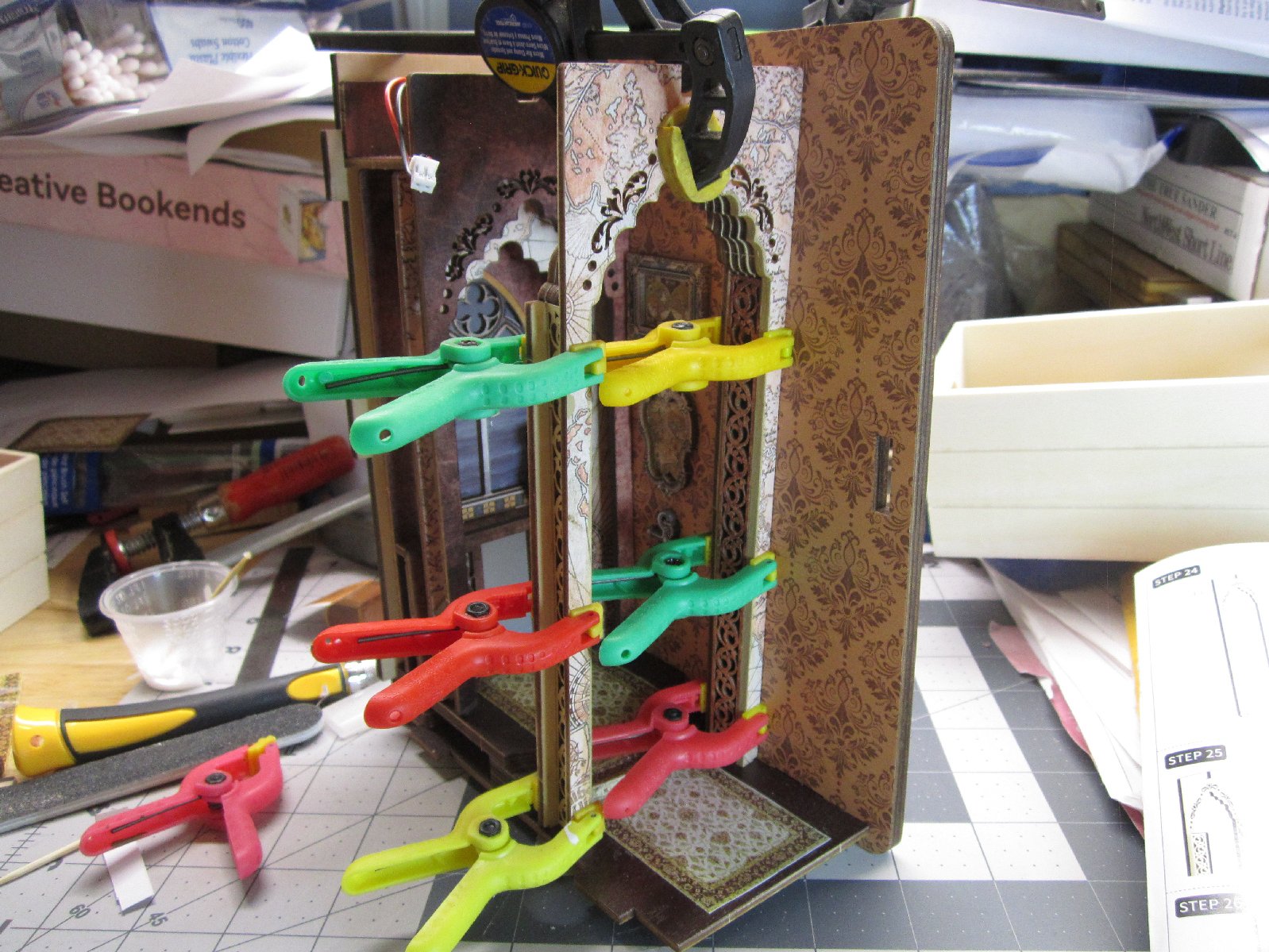
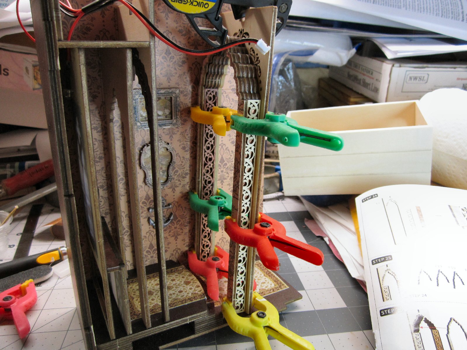
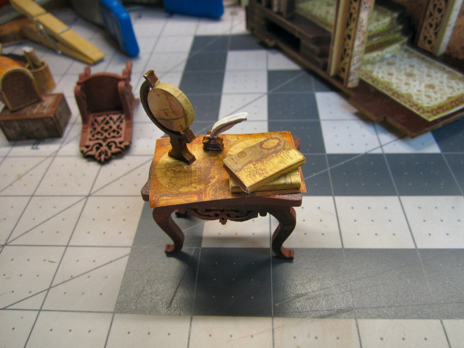
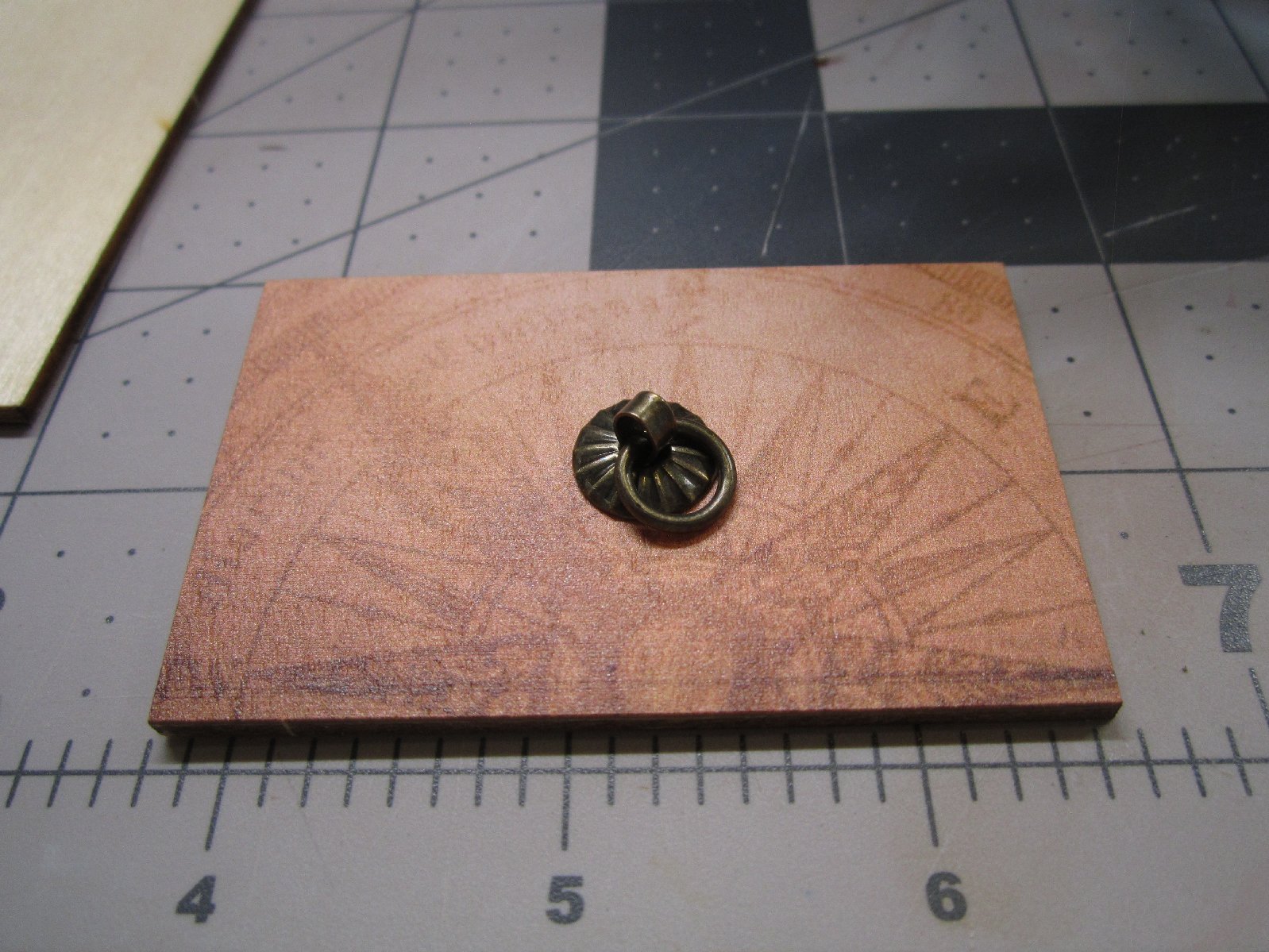
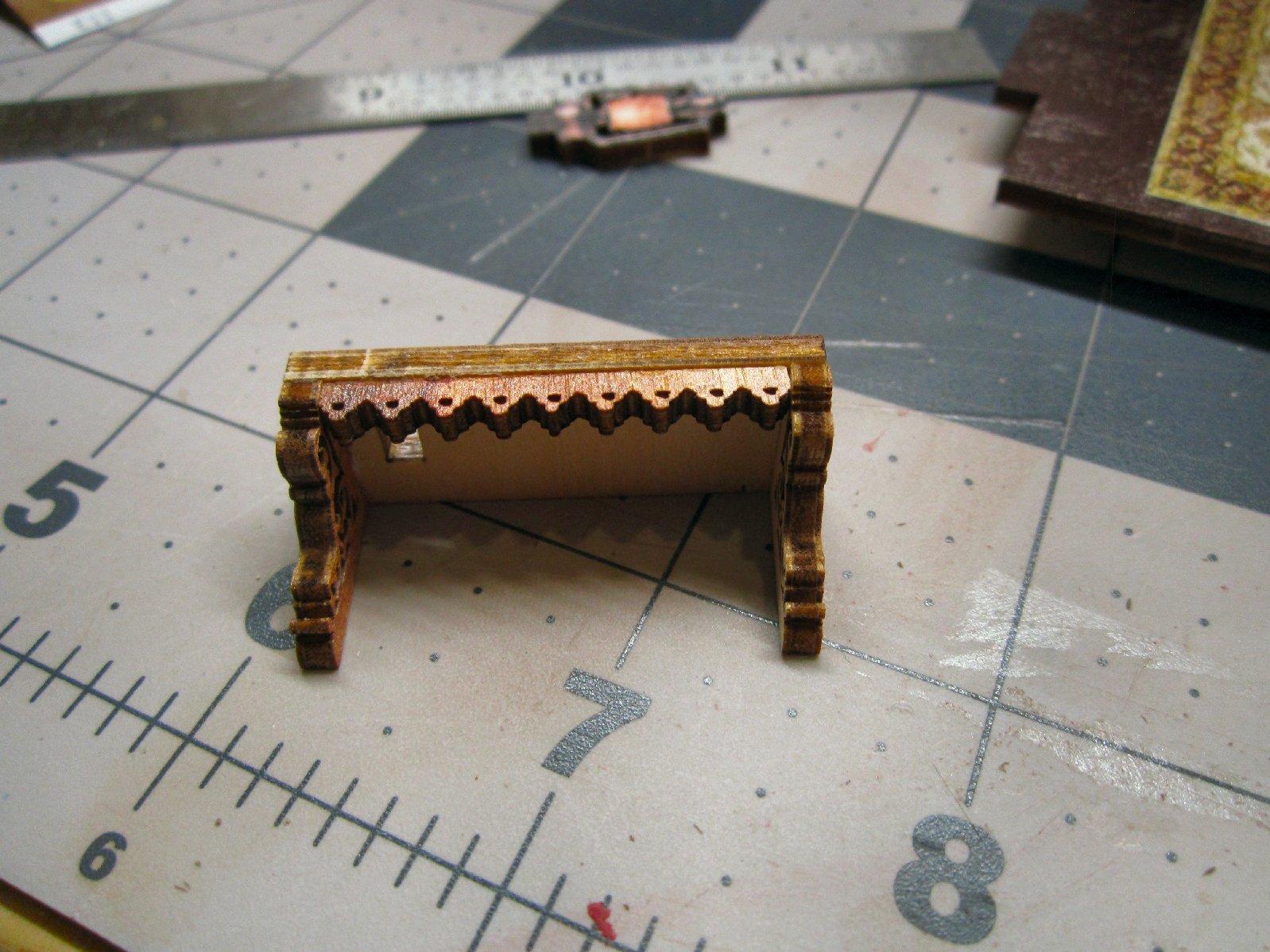
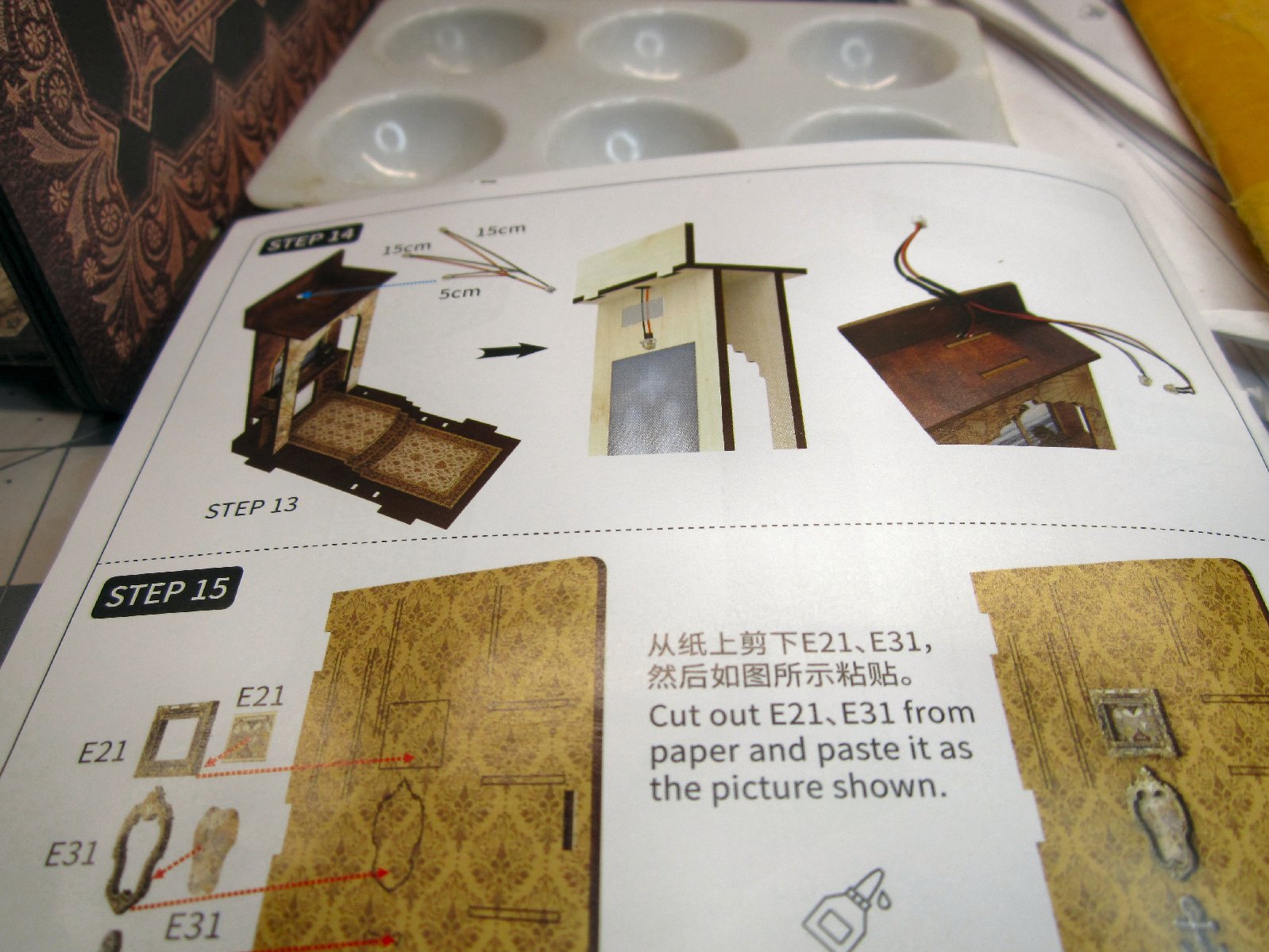
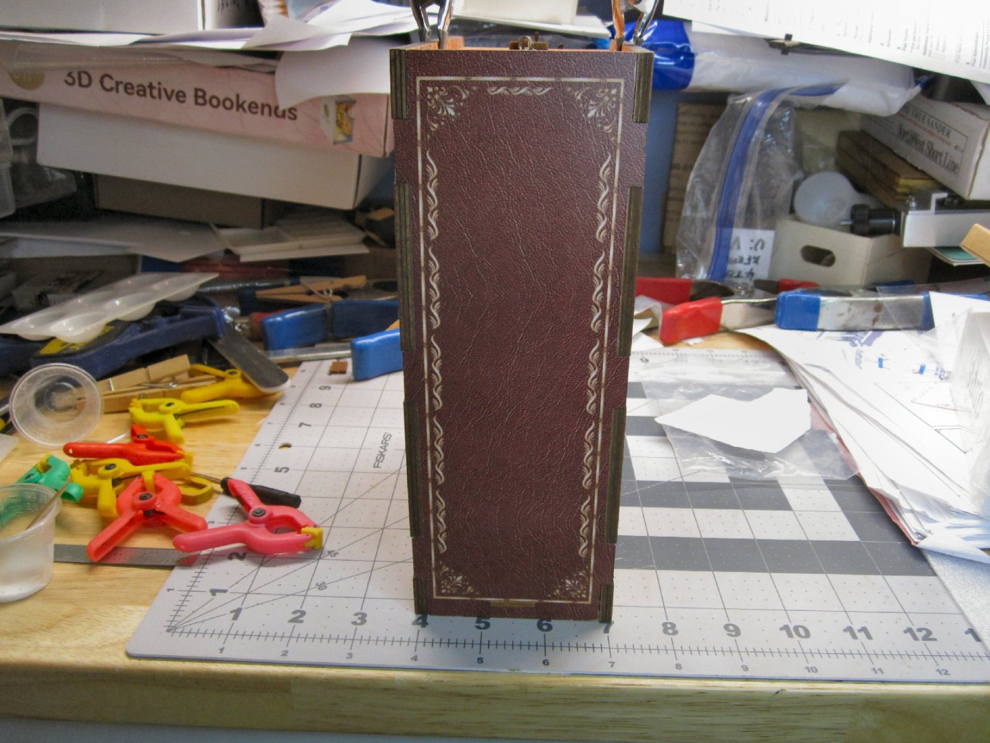
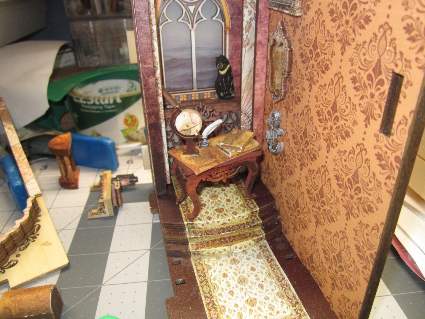
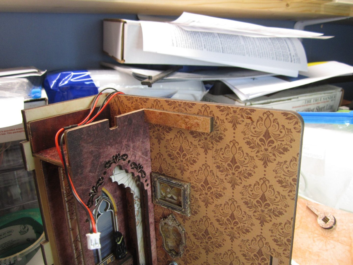
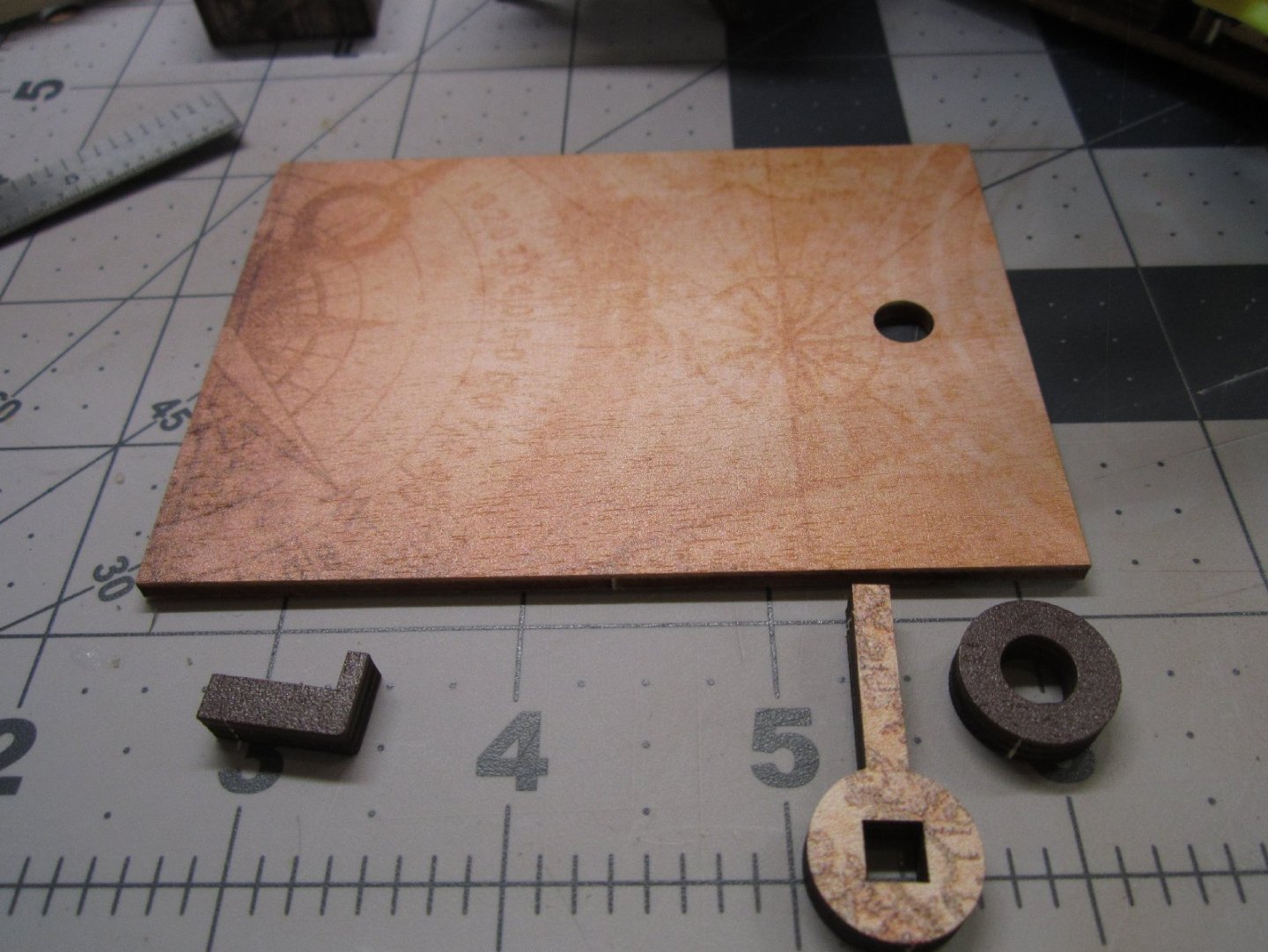
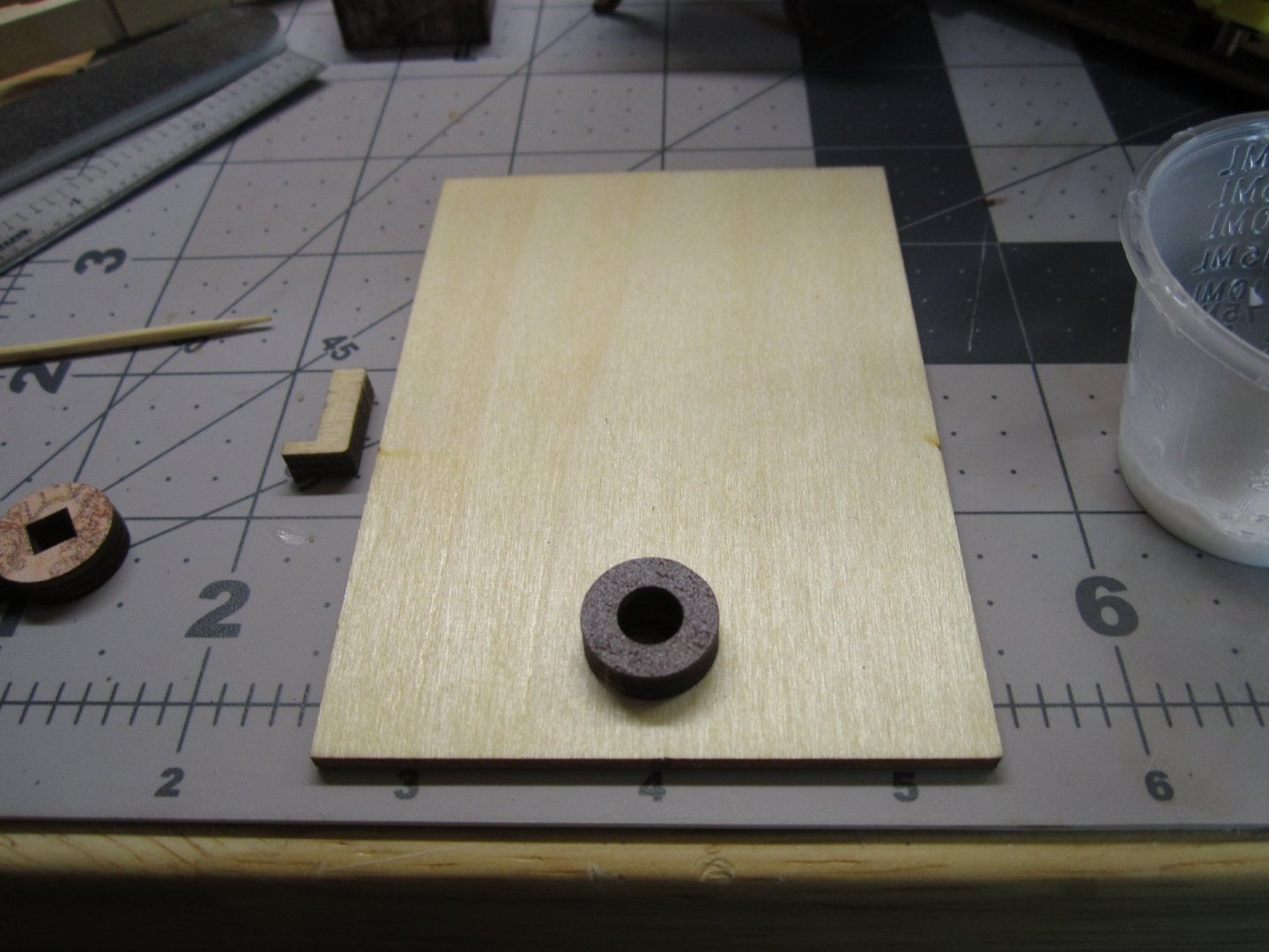
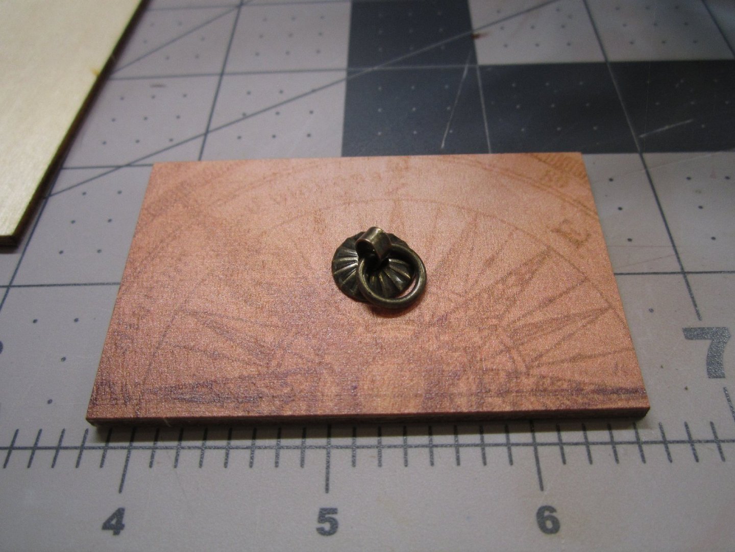
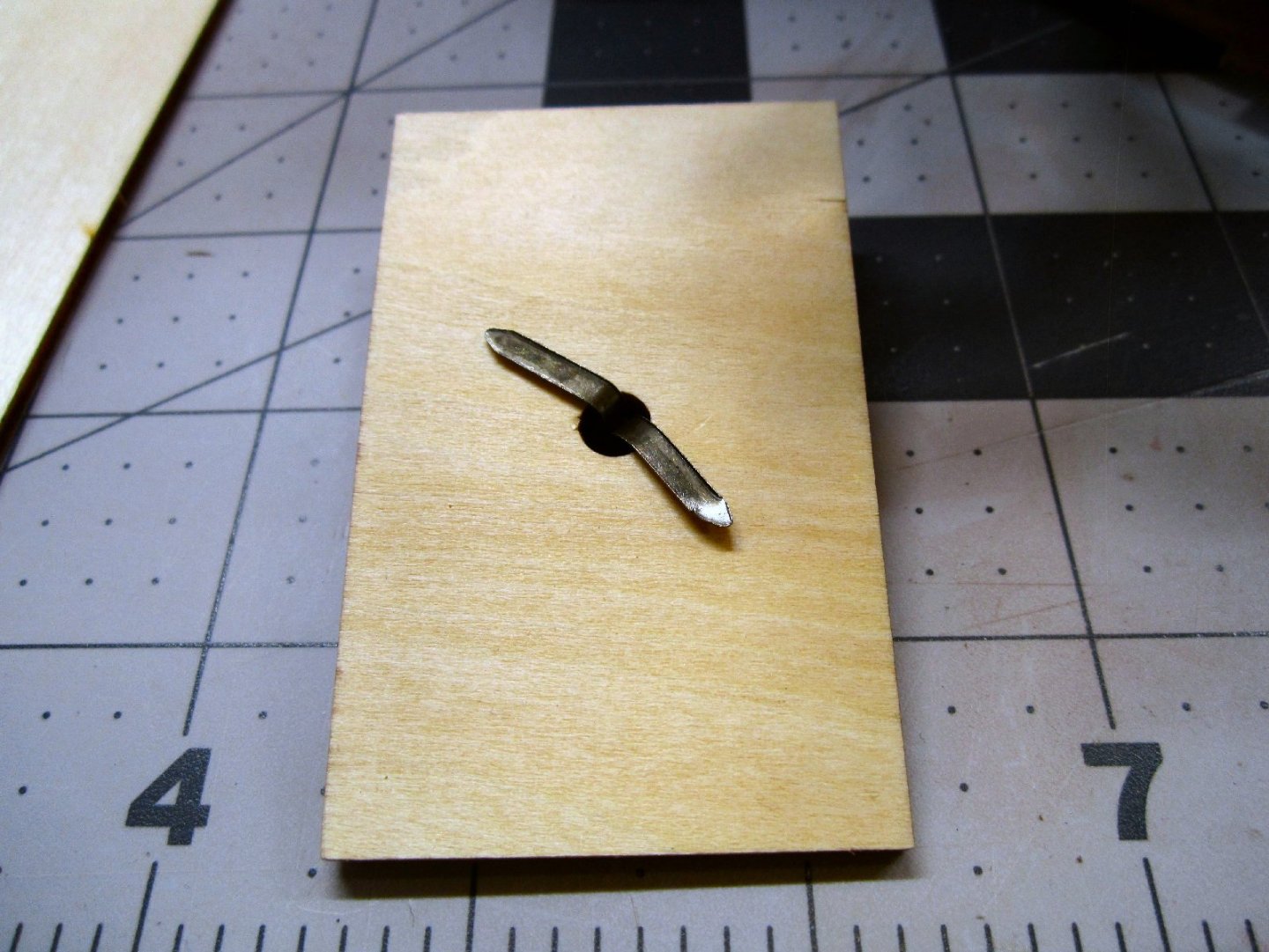
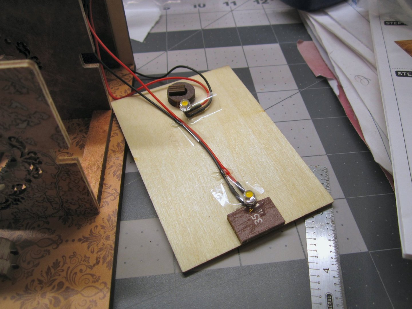
Part 006 The front archway is the next section to assemble. It has a printed front wall with lattice work side walls in the opening, several individual arches to fill the top in, and a printed back wall. This photo shows the lattice side walls and the parts that are layered to form the ceiling of the arch, glued to the front wall. In this picture the printed back wall has been glued on. The printing on this wall will never be seen, but it was nice that they added this detail. Once all the parts were glued. I set the assembly in the model, and clamped it, to hold all the pieces in alignment. This is what the finished assembly looks like in place. At this point it was not glued to the model, I have other parts to go in first. The details were added to the table, next. The top is covered in a map, which hides the exposed tab ends, a globe, an ink well and quill, and the two large books. I painted the edge of the quill off-white, used a gold-yellow pencil for the edges of the globe, and chocolate brown paint, for the globe frame. When the glue dried, I glued the chair and table into the back of the scene, as well as four upright, and one leaning book onto the top of the cabinet (one the left). The details were then added to the shelving unit, as well as the scroll work at the top of the shelves. Finally, three books were glued behind the picture frame. A part was glued in that serves to support one side of the ceiling, and space the top of the front arch. The ceiling over this section was assembled, next. It will span the area from the brown arch, to the back of the front of the model. The other two LEDs are attached to the underside of this to light the interior. This ceiling will be glued in place, and has a hold down latch for the piece that covers the battery box. The four parts of the ceiling are shown, below. The doughnut shaped ring, is glued to the underside of the ceiling as part of the latch assembly. To complete the ceiling, the “L” shaped part is pushed through the hole with the short leg positioned at the doughnut, and the handle is glued to the protruding section. The “L” and the handle must be free to turn in the hole. The LEDs are bent at 90 degrees and glued in place on the underside of the ceiling. To position the LED at the front, of the model, one of the extra book blanks is glued at the front. Care must be taken that the wires for the front LED run down the center of the part. There are notches in the tops of the arches these for them to run through. I taped the wires in place, then glued them down. The wires that exit at the back will be twisted together to fit through the notch there. The battery cover is the next part to build, it is a simple piece. This is a decorated plywood sheet with a central hole, the fancy fixture is installed in the hole as a handle for the cover. The fixture is a flat pin that captures the washer and ring. The pin is pushed through the hole, and bent over on the back side. Part 7 will cover the completion of the model.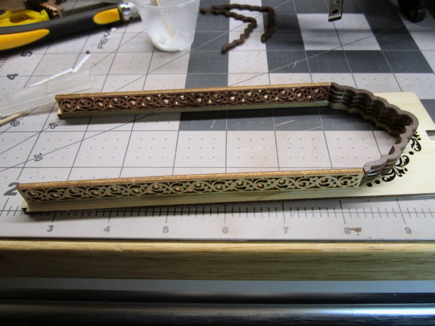


-
"Sailing Memory" by thibaultron - Book Size Diorama
thibaultron replied to thibaultron's topic in Non-ship/categorised builds
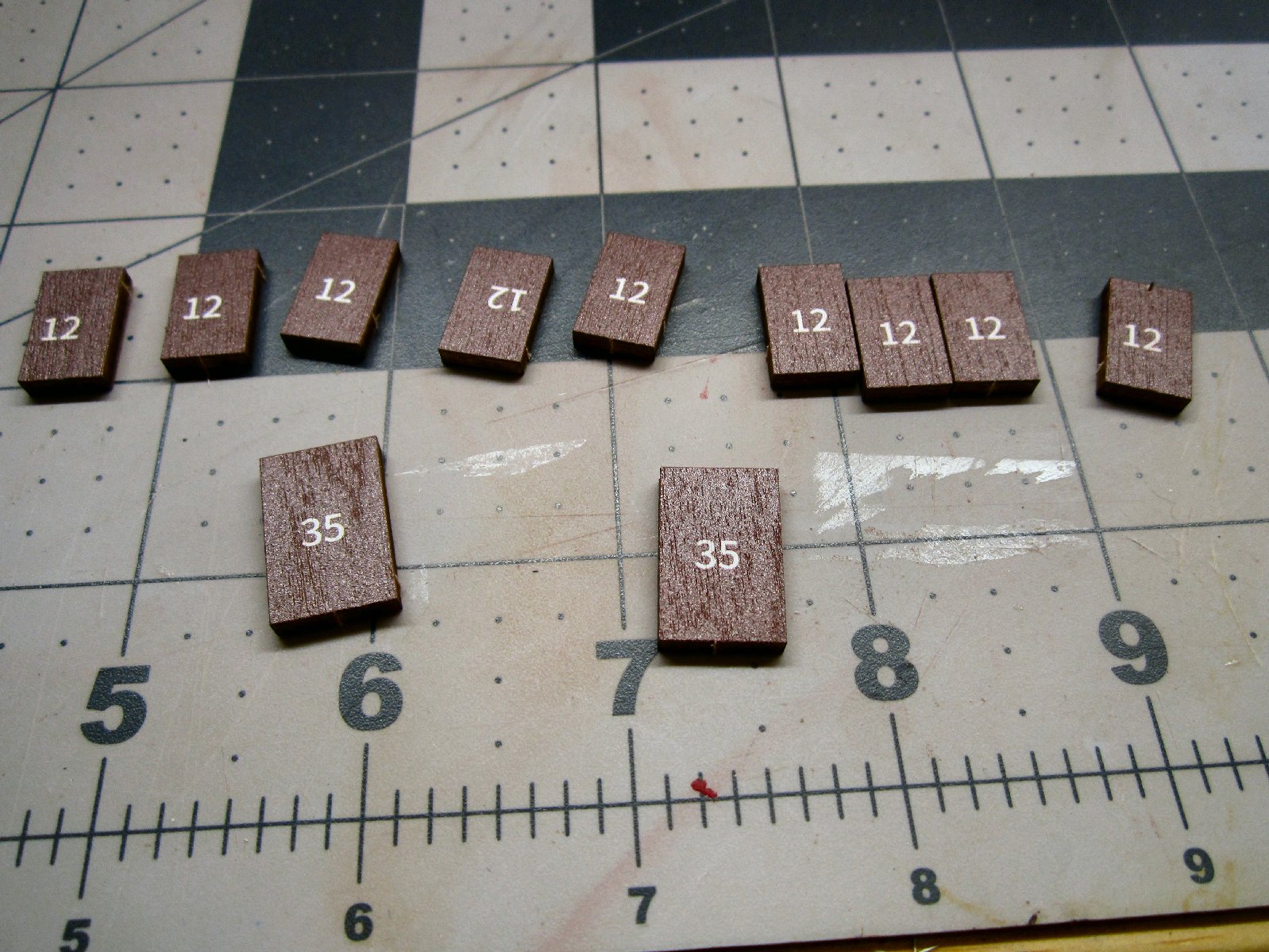
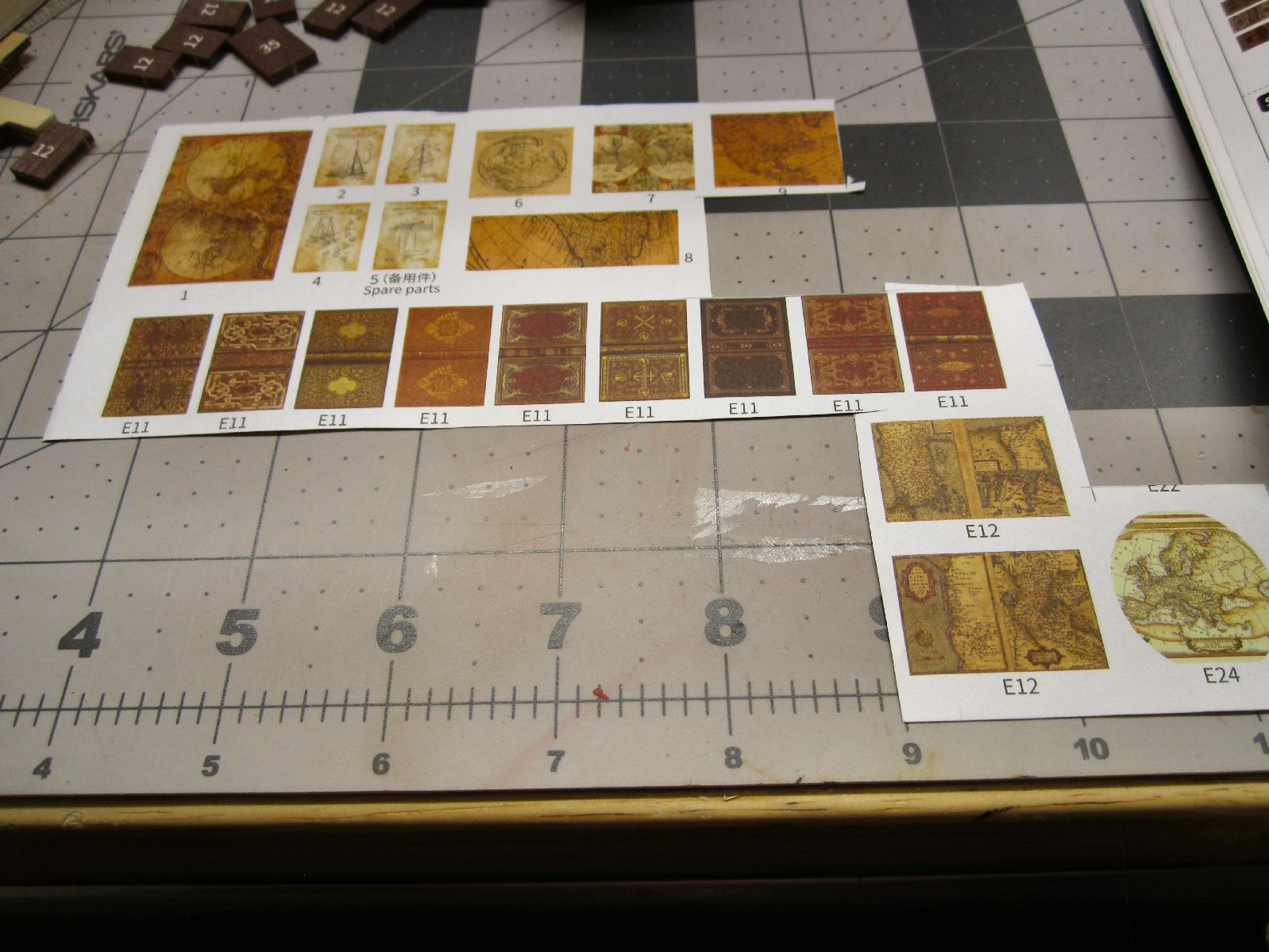
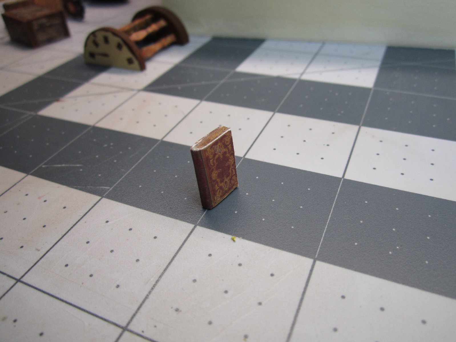
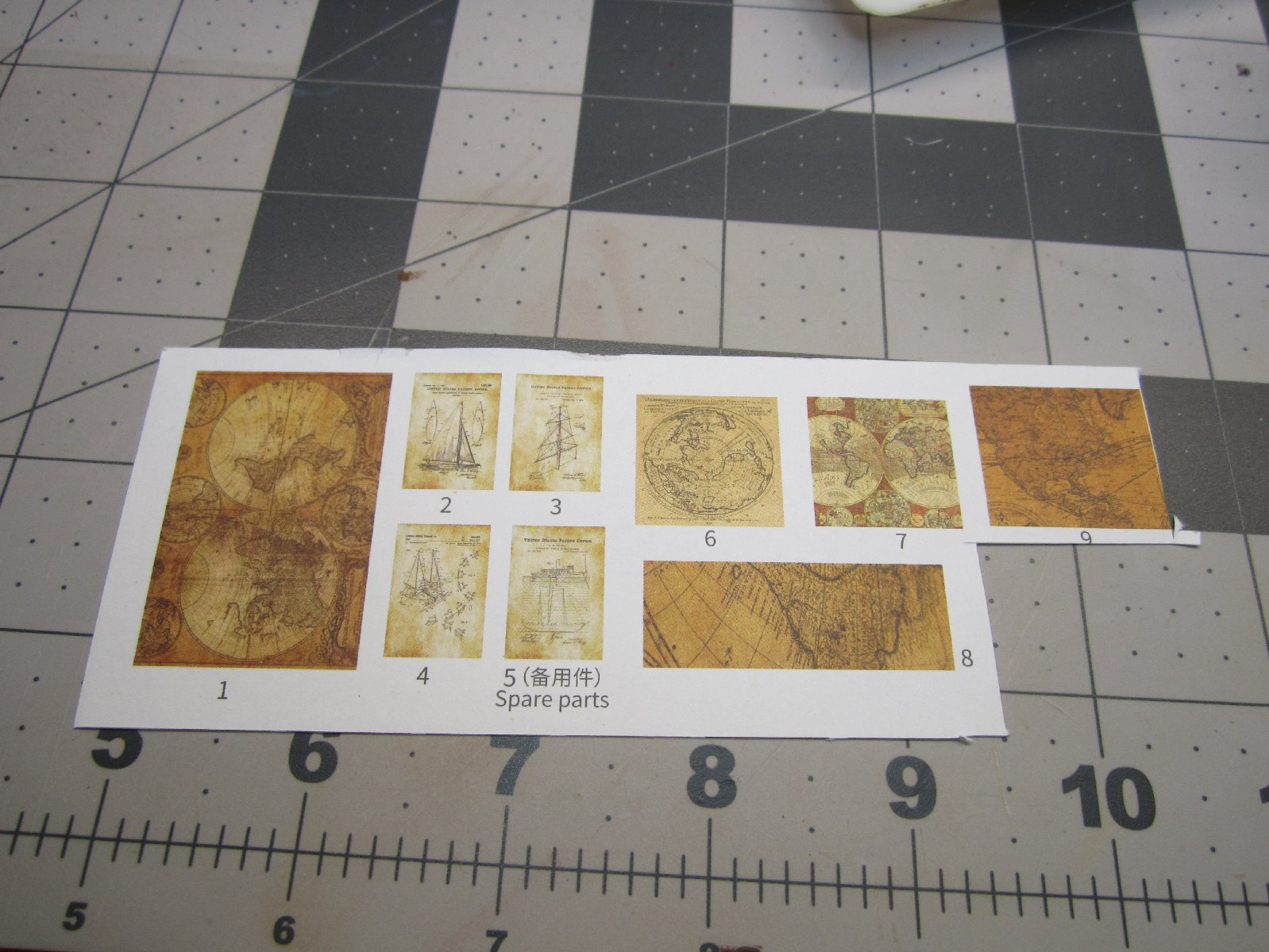
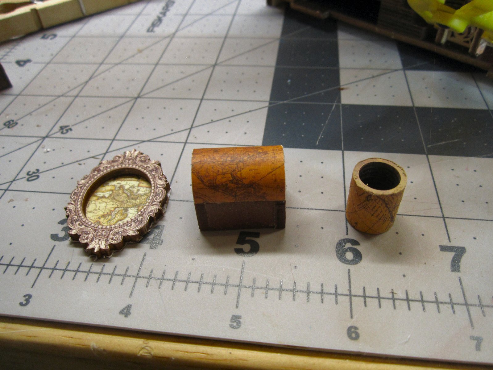
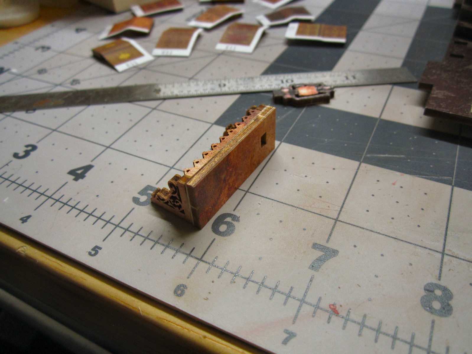
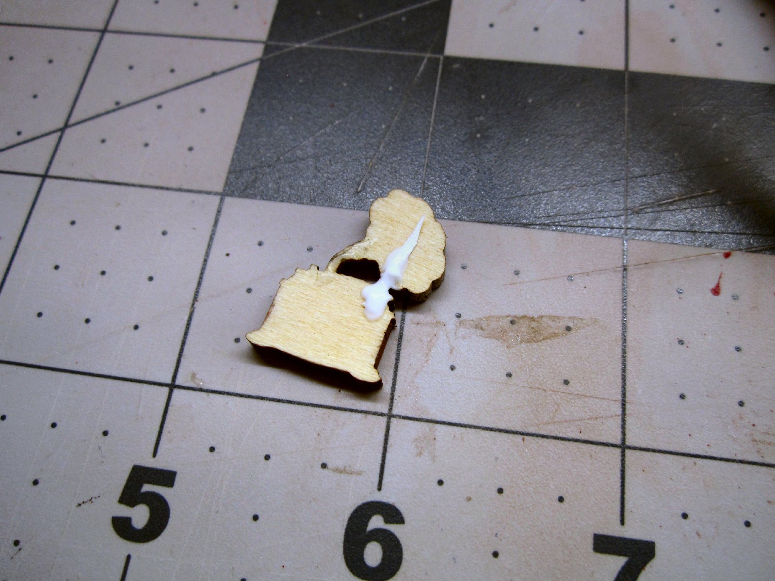
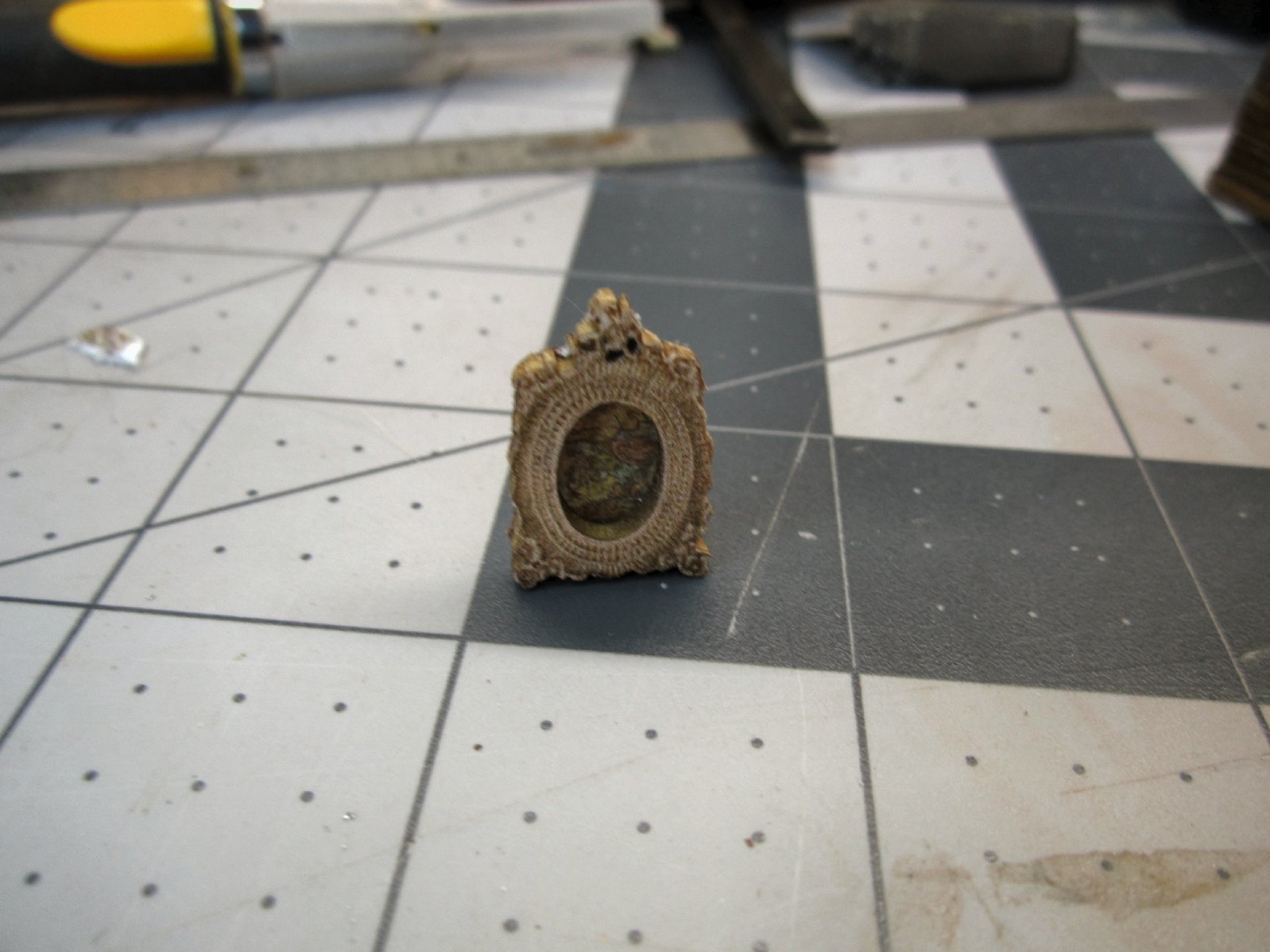
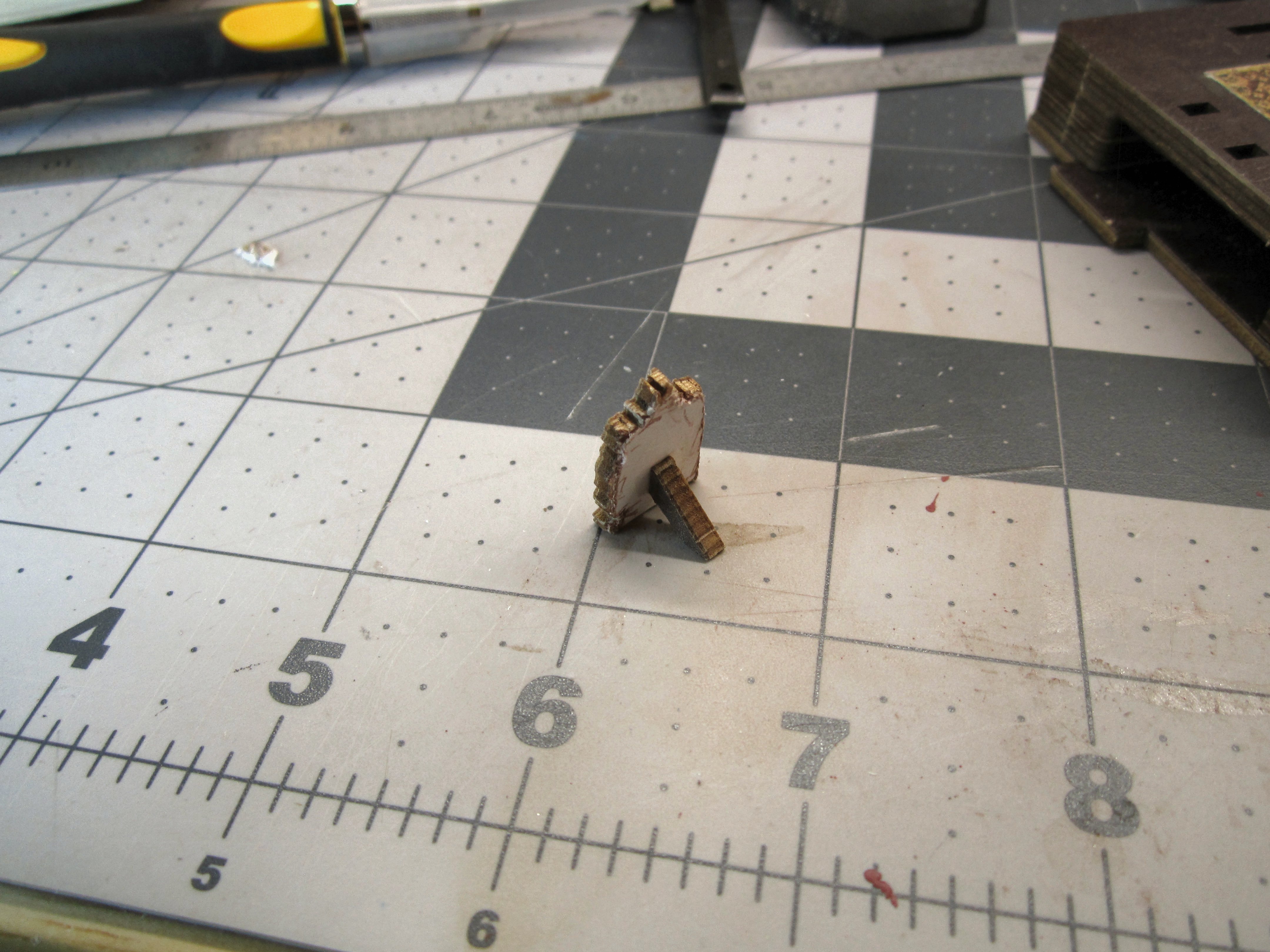
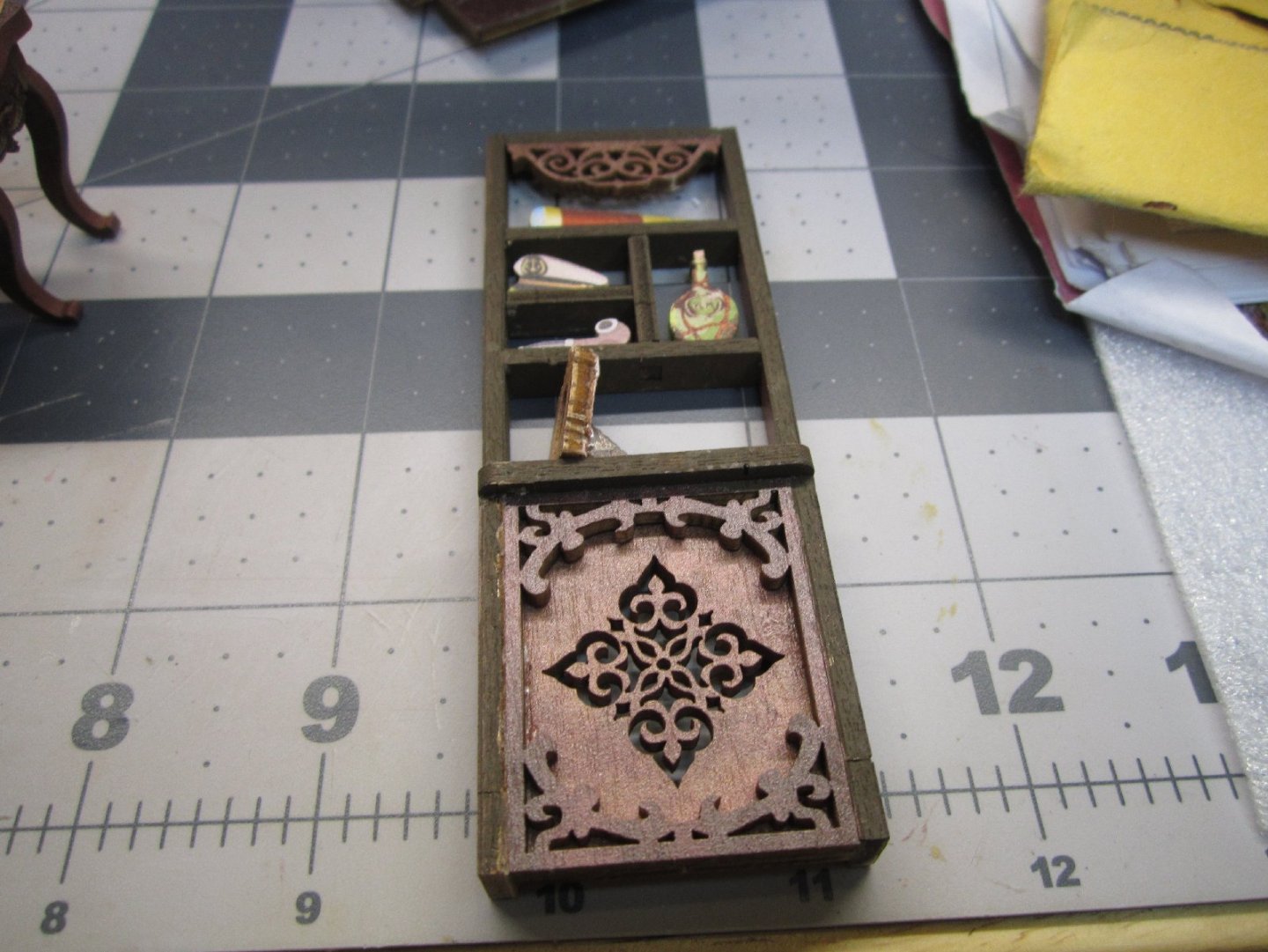
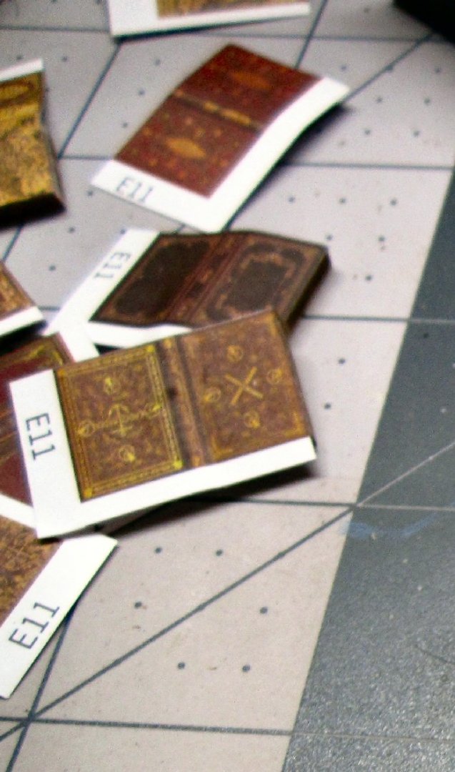
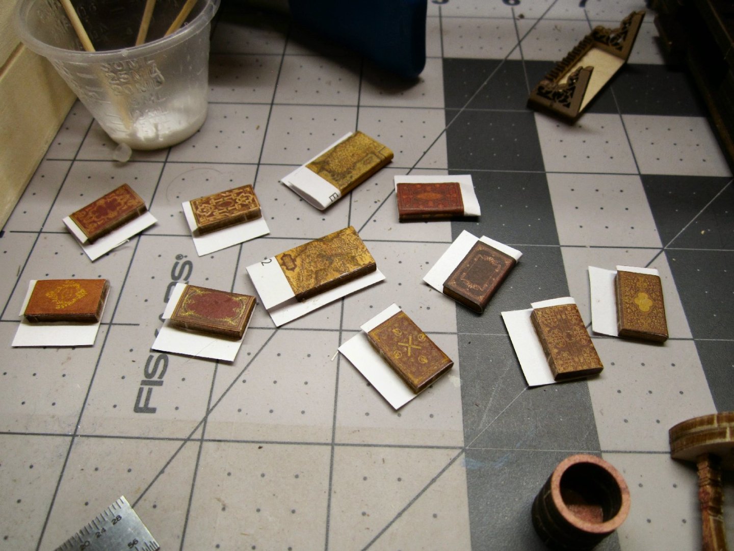
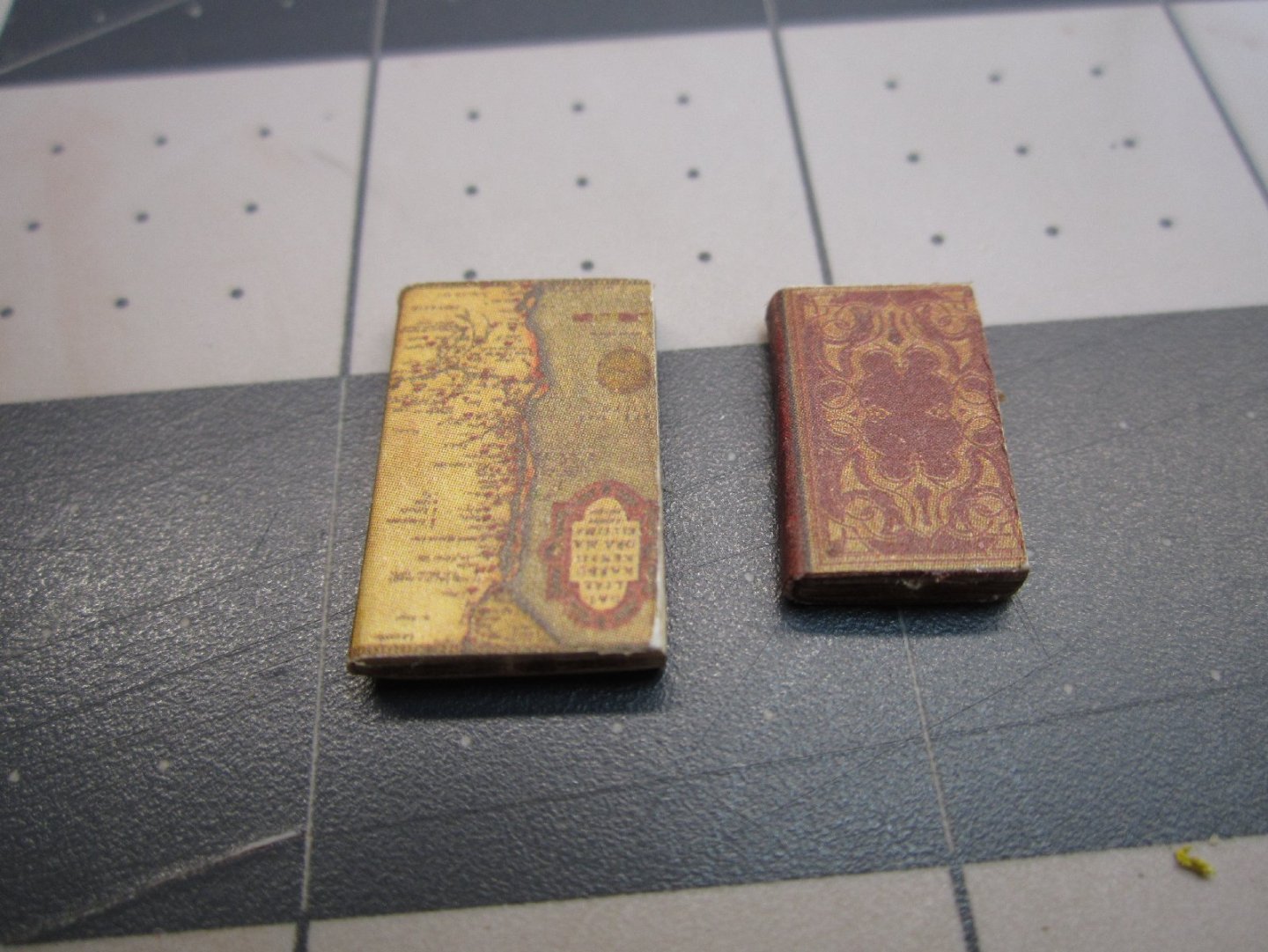
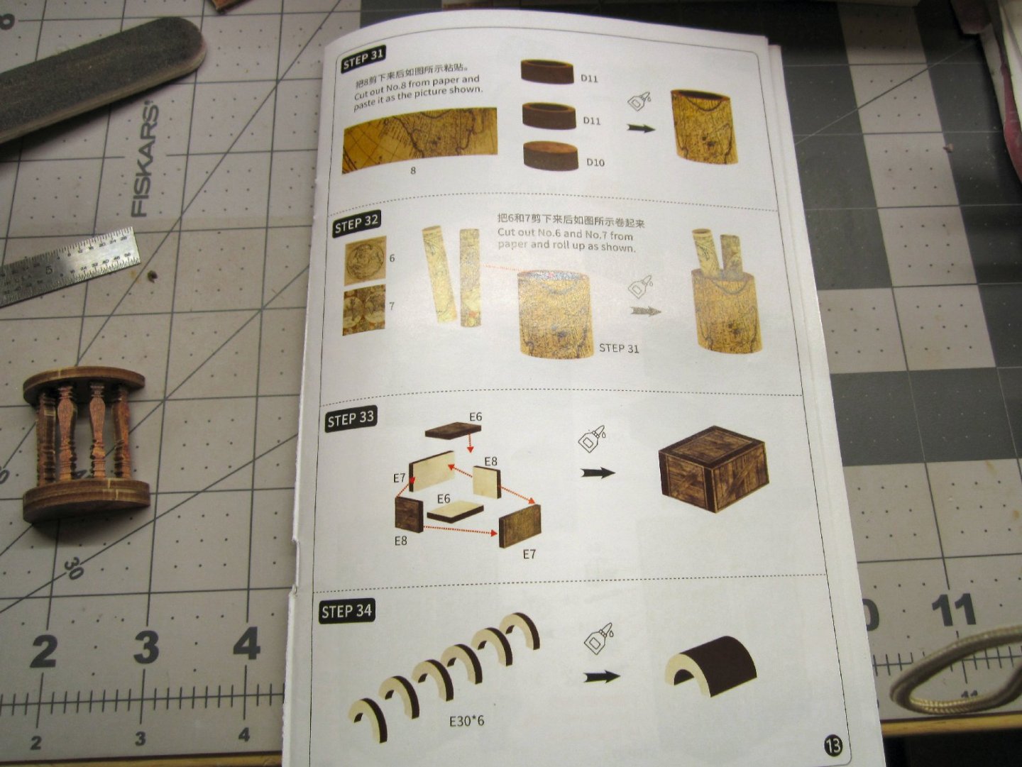
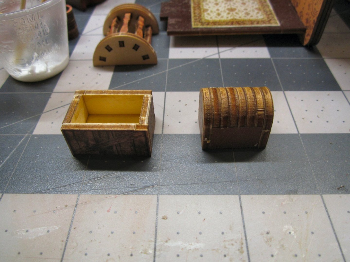
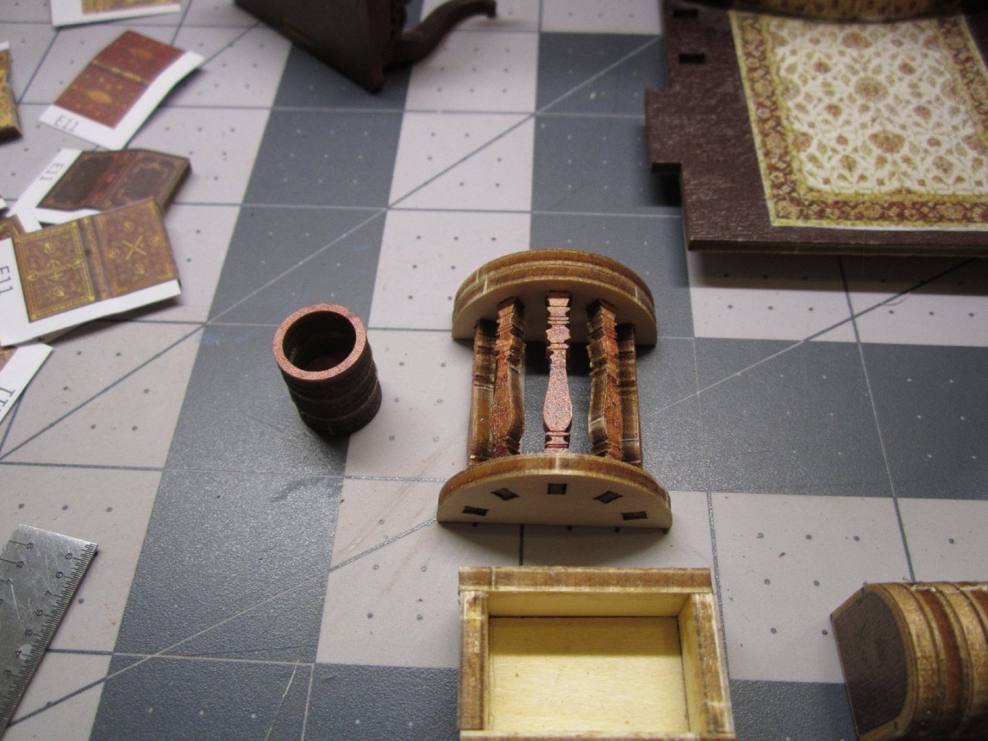
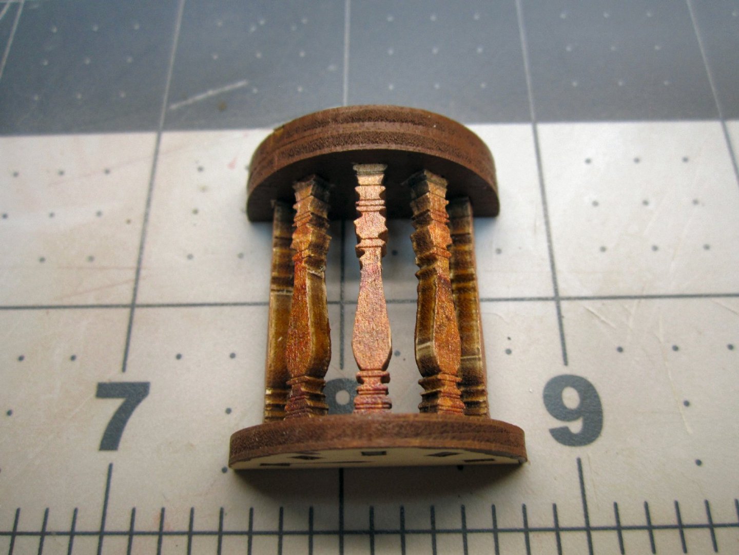
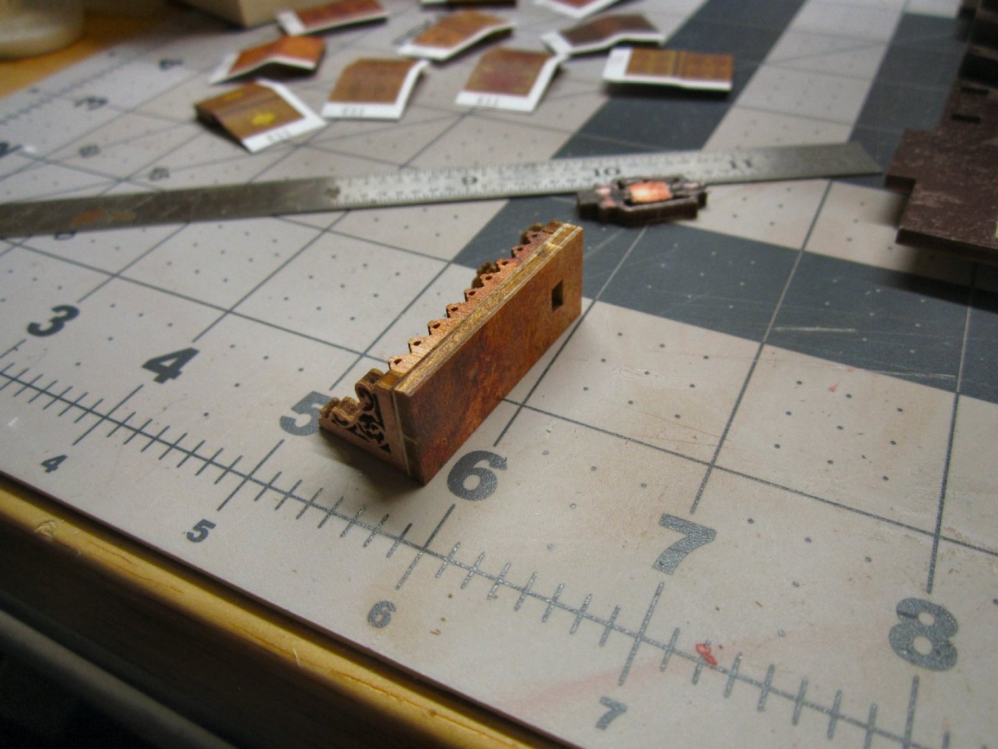
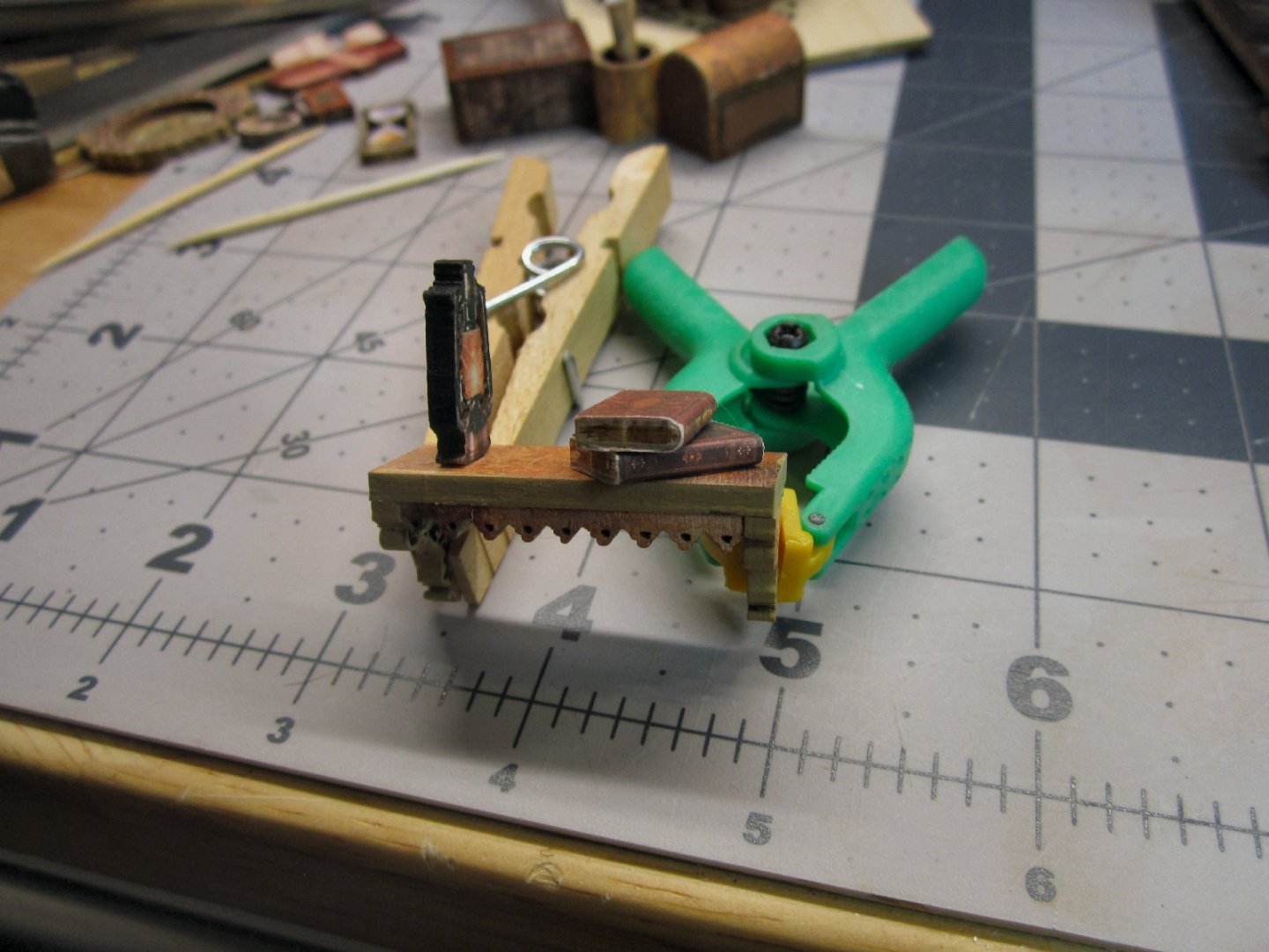
Part 005 I tackled the books next. The kit supplies wood blanks and printed covers to be glued on them. This picture shows the raw blanks, nine for small books, and two blanks for large ones. The printed covers are shown below, they are the E11 and E12 graphics. I started by sanding the edges of the blanks, to smooth off the holding tabs the laser left. I then rounded one long edge to represent the spine, and also to allow the cover to flow smoothly around those corners. I trimmed the covers on one long edge and one short edge, leaving one completely trimmed corner Then, I separated each cover Leaving as much unprinted area as possible, to use as handles. The trimmed edges formed the end of a cover, and the base of the book. I applied glue to the cover end edge, and placed the trimmed corner on the blank. I carefully bent the cover around the spine, to make sure everything was lined up, then unbent it, and set the books blank side down, and let the glue dry. After the glue was set, I applied glue to the opposite side of the blank, and the spine area. Then, I bent the cover around and held it in place for a few seconds, until the glue grabbed. I set the books back down, with the glued side down, to hold the cover in place, and let the glue fully dry. After the glue was dry, I trimmed the extra paper away, with a hobby knife, then gently sanded the edges to clean off any extra paper that was left. This photo shows one of the completed small books. This picture shows a large and small book. The next steps are assembling some small details. The photo shows the instructions for some of these. The first is a trash can shaped map holder. The next panels show the crate, and the assembly of the top of a chest. These pictures show these details during assembly I painted the semi-circular table’s exposed areas. Next, came covering the map holder and chest. The number 8 graphic is the map holder cover, and 9 is for the top of the chest. When I went to cover the chest, the print is too short, to cover all of the top, from front to back! If my printer was working, I would have stretched the print, and printed another to use. I painted the exposed top to hide the raw wood, and will have to leave it at that. There is another picture and frame, that is shown further on in the instructions. Graphic number 6 is the picture for that frame. This photo shows the picture, the covered chest, and the map holder, skinned. Later two of the graphics are rolled and glued in the map holder. I painted the top rim of the map holder, as I gouged the printed color, trimming the excess paper. There is a shelf that goes on the right wall, that will hold a few items. The next two photos are the basic shelf assembled. This shot is the shelf with two books and a lantern mounted. I painted the edges of the lantern handles and top black. I forgot about painting the base, before I glued it on. Thankfully the laser char is a close color, to the base.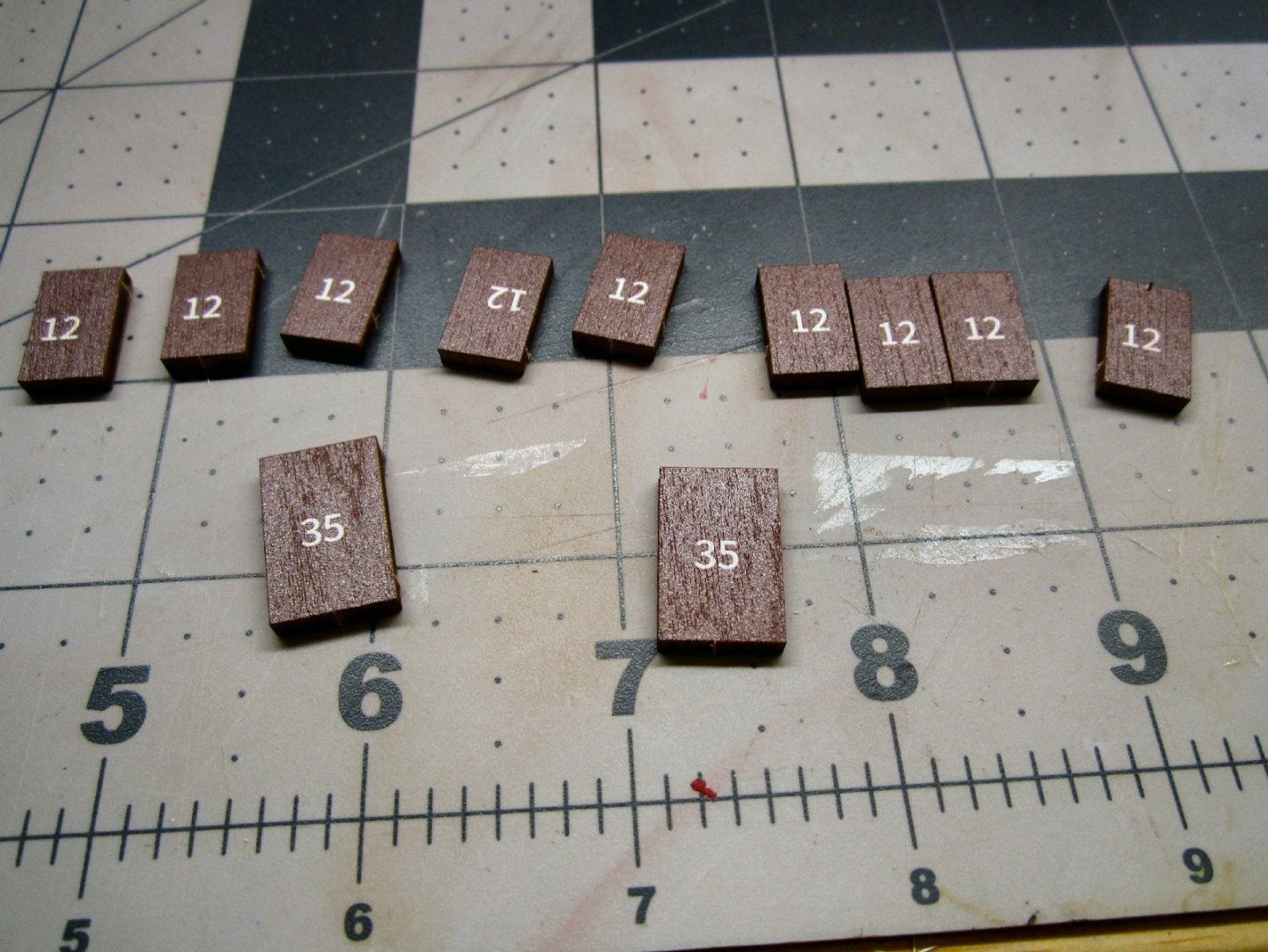


-
"Sailing Memory" by thibaultron - Book Size Diorama
thibaultron replied to thibaultron's topic in Non-ship/categorised builds
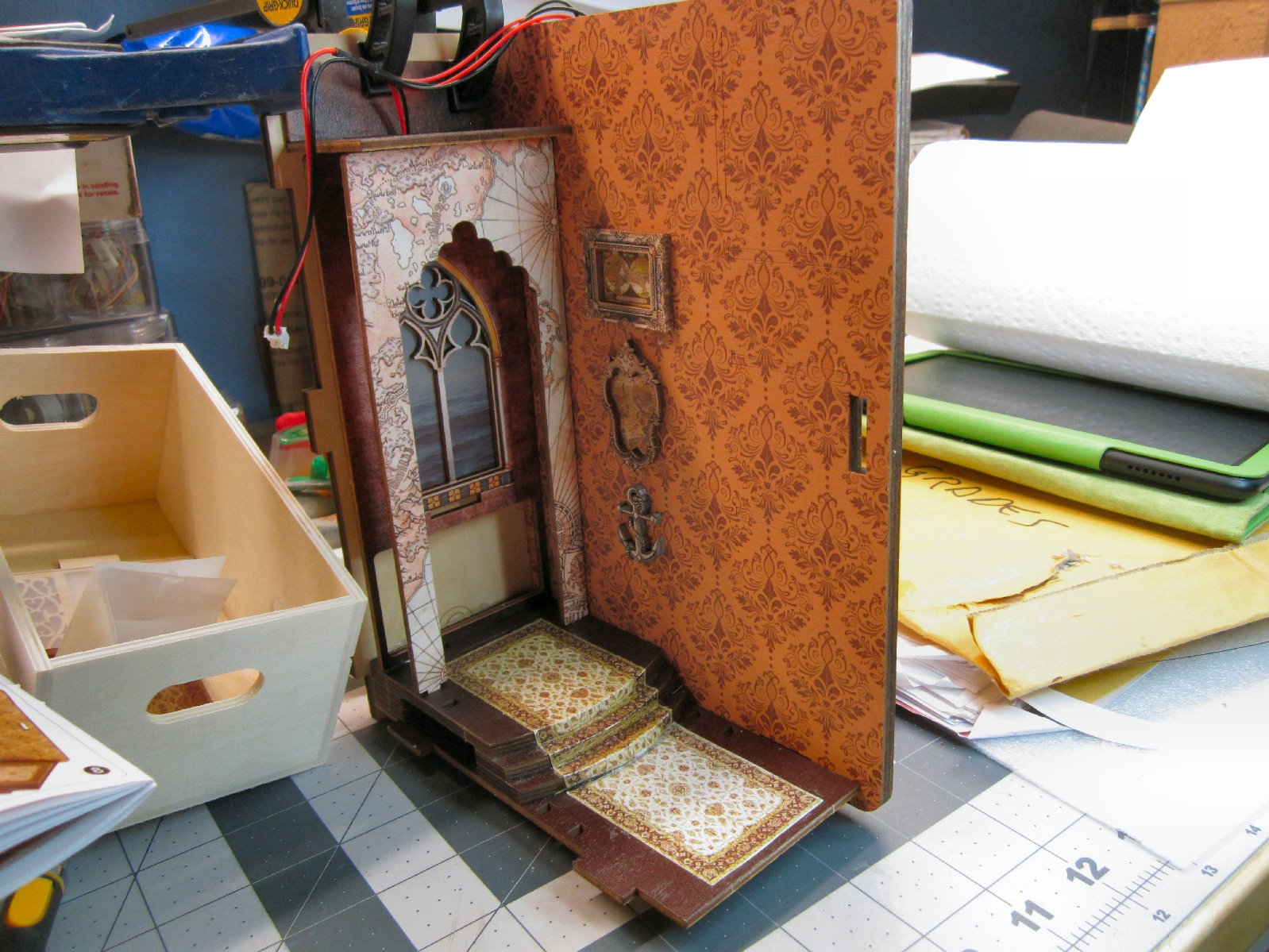
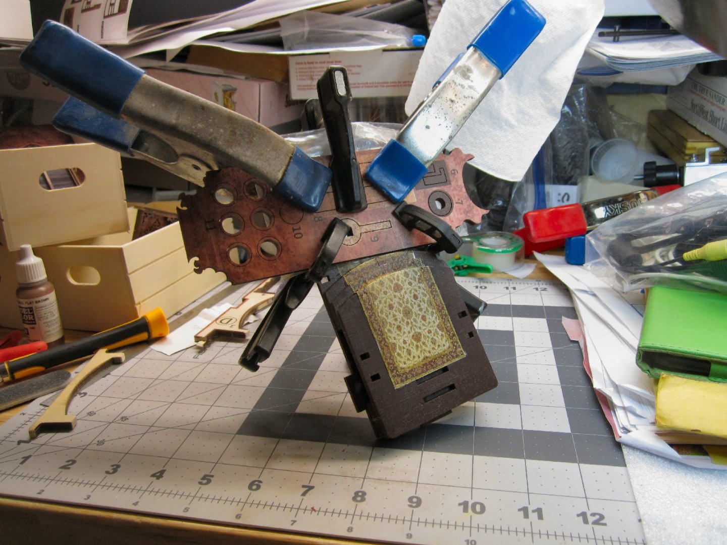
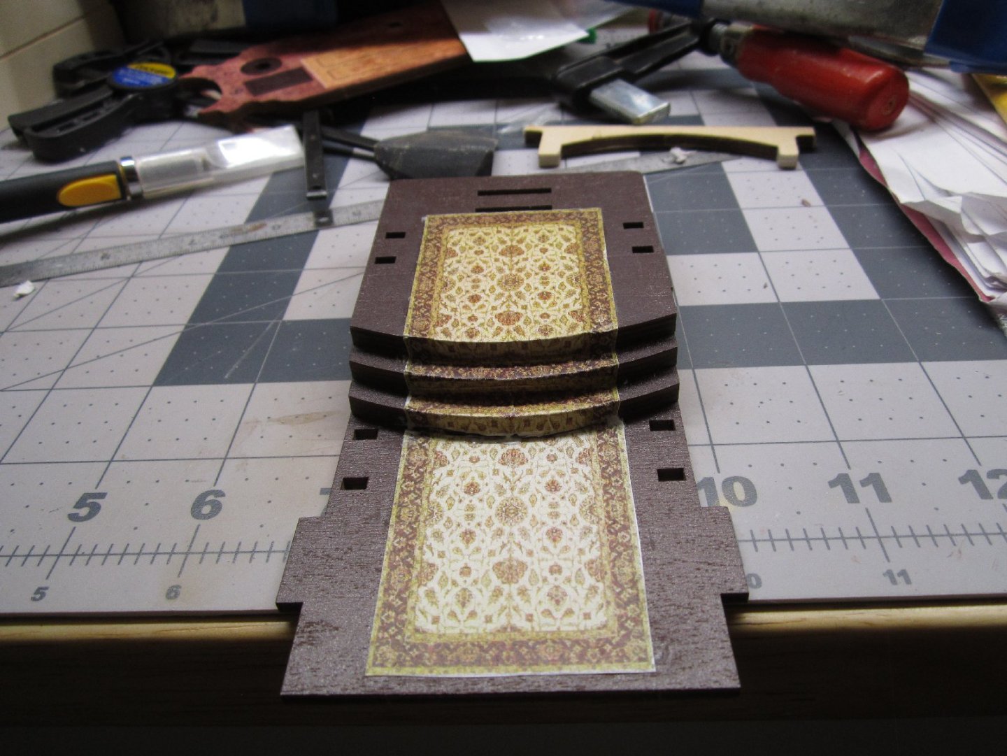
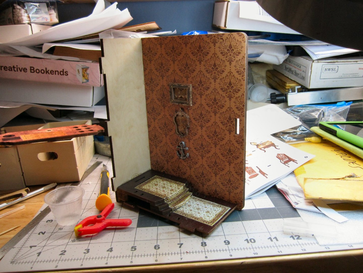
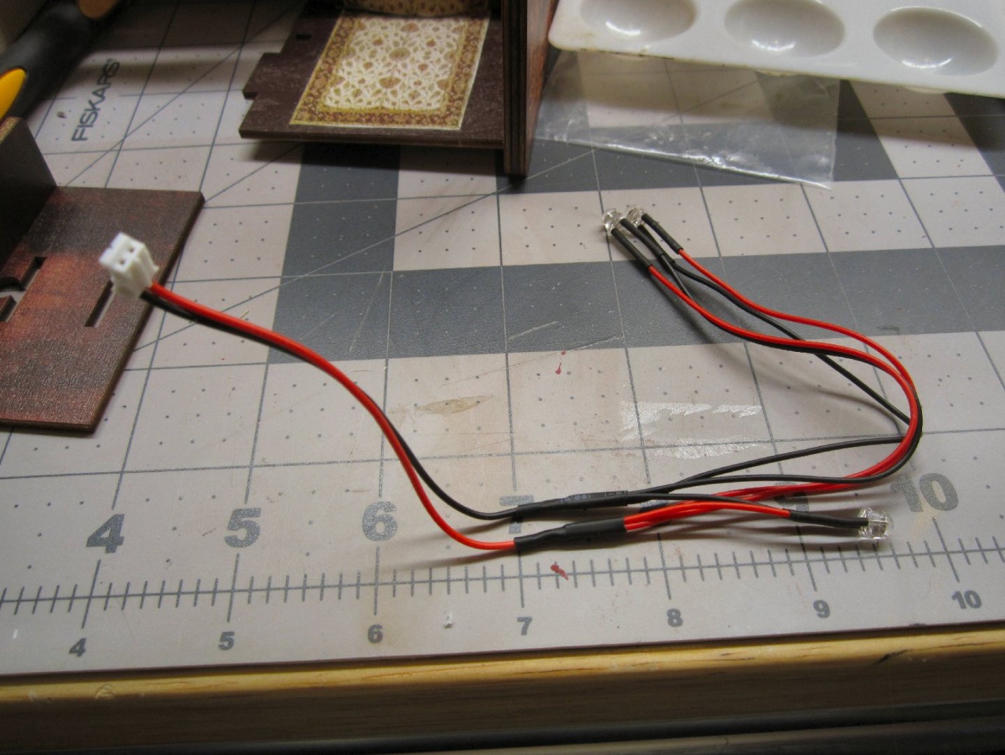
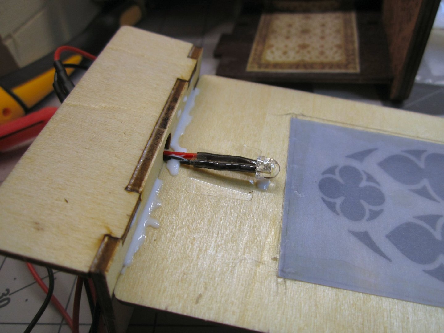
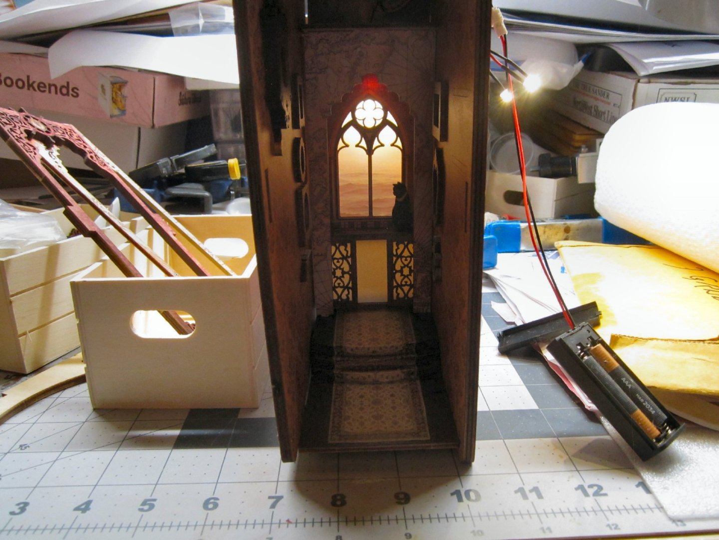
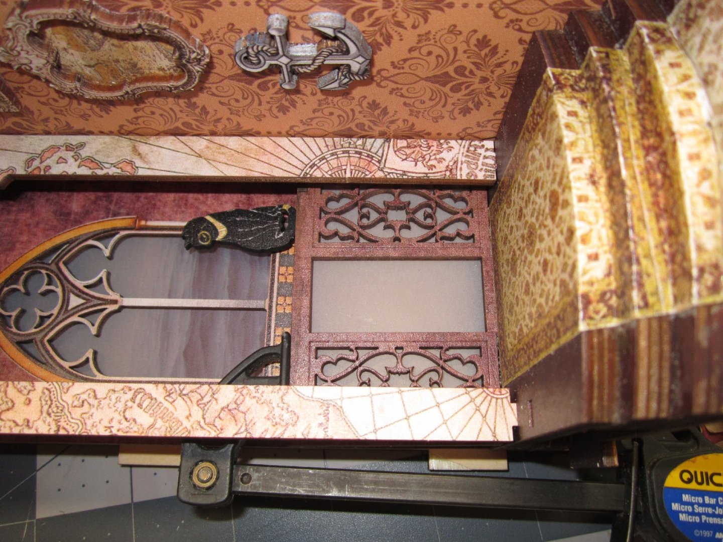
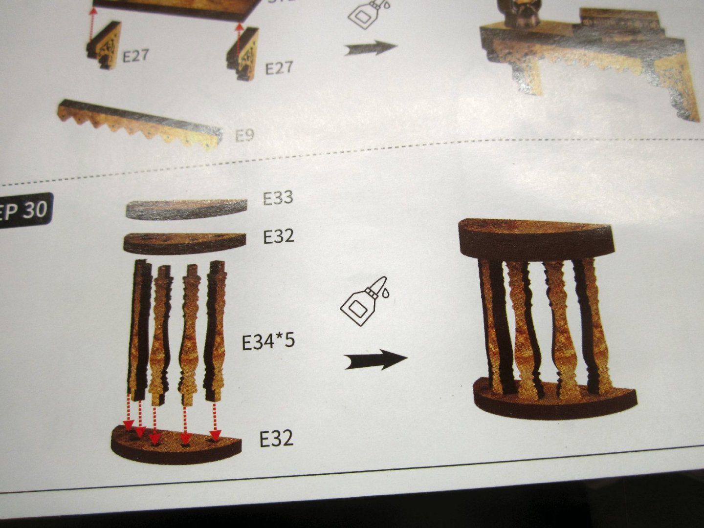
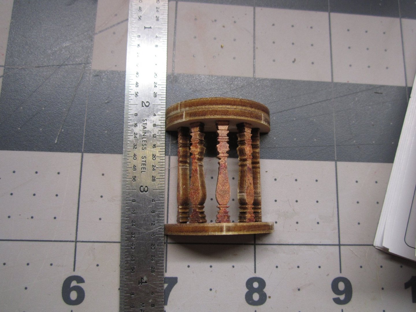
Part 004 While using pencils to color the edges of the Victrola I broke the area of the neck of the trumpet, not all the way, but it was floppy. To fix it I added a bead of glue along the back of the area, and as added strengthening, I glued a sliver of paper to the back between the mouth of the trumpet and the base. After a couple rounds of adding more glue along those areas, the part is now quite strong. After the last layer set, I trimmed the pointed area of the paper off. My acid-free paper came a few days ago, and I eagerly loaded it into my laser printer, to print a new copy of the carpet! I ran the print, with a couple extra, and got a shock when I looked at the prints, they were in Black and White! What the h..l! Then I checked the printer, the magenta cartridge had just run out of toner! AAAAHHH! Not immediately having the money for a new set of toners, (the others were also low), I dug the old prints I did on regular paper out, and sorted through them to find the best two. I took the slightly darker print, and proceeded to set the carpet down like in the trials, I ran in a previous part of the thread, this time gluing the sections down as I went. It went well until I got to the last area that was to go down on the lower level, it was crinkled a bit and bowed up in the middle. No problem, I just laid down glue over most of the area, and clamped it down, as shown below. Disaster! The glue had soaked into the paper, and it looked like the carpet had been flooded with water! I had glued the other areas at the edges only. Luckily, I had not let the glue fully dry, and with much effort, and a lot of strong language, I managed to get that section and the glue removed. I could not use Isopropyl Alcohol on it, as it affects whatever paint the manufacturer applied to the kit parts. I cut the carpet at the corner between the lower floor and the riser for the first step. This left the section on the riser loose, as I had only applied glue to the horizontal areas. I took the slightly lighter print and cut it a little longer than needed, the end of this extended past the front edge of the floor, and clamped it in place. I pressed it in place, with the curved sprue section I used to form the rest of the carpet, then ran a hobby knife down the curved corner. This gave me a guide, to trim the unneeded area off. I moved the sprue back a little and holding it down tightly, after making sure it was parallel to the front edge of the floor, I trimmed the extra off by running the knife down the sprue edge again. This gave me a good matching curved edge. I glued the new floor section down at just the edges, and now, no “water” stains. The two prints are almost the same color, and the difference is not noticeable. To secure the bottom edge of the riser, I held it in place and ran a bead of glue on the outside of the corner. There was a little of the floor showing at this joint after the glue dried, so I painted the corner with Vallejo Flat Earth, which closely matches the tan areas of the carpet. Even if someone does notice the different shades of the two pieces, I will just say that Oriental Carpets are handmade, and even two “identical” carpets will vary a little due to the hand dying process! “That’s my story and I’m sticking to it.” Here is a picture of the finished carpet. Below, is a picture of the small standing picture and frame, that I forgot to get went I took the picture of the hanging frames. I, next, assembled, glued, and clamped the right-hand cover and spine, to the base. Here it is after it dried. You can see the slight gap on the left-hand side of the carpet. Once painted, this disappeared. The next parts I assembled were the back wall area and the first arch. These were supposed to be assembled earlier, but I wanted to wait to glue them in when I had something to support them, in the correct orientation. Before I glued them in, I installed the first LED (see the instructions below), the one that will backlight the window. It turns out the clear stickers are to be used as tape to hold the wires in place. I used one to hold this LED’s wires, and then additionally glued it in place, also. Here is a picture of the LED assembly. The short one at the bottom, is the one that is used here. This photo shows the LED taped and glued in place. The ceiling and first arch make up the rest of this sub-assembly. The picture, below, shows the installed parts. I did not glue the two legs of the arch to the floor. The cover is slightly warped, and the left side of the arch sticks up a little. The arch is captured by the floor and ceiling tabs, so it can float free at the bottom. There are two more arches that go in front of this one, so any gaps will be hidden. I hope everything will meet better when the other cover and the front piece are installed, and can counteract the warpage. If not, I will torque the whole assembly and add glue to hold it in the correct alignment. In the picture you can see the gap on the left-hand arch leg. I wanted to see how the backlighting looked, so I set the left-hand cover in place and turned on the LEDs. The first shows the model with the interior dark, so I could get the whole effect. When the model is done, there will be two more LEDs lighting the interior. The second picture is with some overhead light added. I glued in the cabinet, and clamped the left side, so the bottom, sat firmly down on the floor. The instructions, would have had me gluing a set of books where the head of the clamp is. I’m glad I waited until this was in place. The next assembly, is a small semi-circular table. The instructions have a mistake, that I did not notice, until I went to paint the edges, while building this. In the picture of the instruction sheet, below, it clearly shows the upper level of the table, having both pieces with the printed surfaces pointed up. This unfortunately, leaves the raw wood side facing the interior of the assembly! I had to paint the underside, as well as the edges, to hide this. The table should be built with the printed side of this piece down. You can see the raw face in the picture below. It was “Fun” trying to get all the spindles in place while attaching them to the semi-circular ends, and that is one reason I missed the error. In any case, once everything was assembled, I use the edge of my ruler to line the top and bottom of the piece up. In the next Part I will be building some of the small details, including the books.


-
Who made this kit? I have the model Expo single mast version.