thibaultron
-
Posts
2,944 -
Joined
-
Last visited
Content Type
Profiles
Forums
Gallery
Events
Everything posted by thibaultron
-
 The tip on painting the fret work is great! Wonderful little model!
- 3 replies
-
- 2
-

-
- Admirals Barge
- Vanguard Models
- (and 2 more)
-
Do you have a higher resolution or larger, picture of the above drawing? If, so I will draw you a 3D print file for that specific cannon.
-
To reduce the surface tension in the thinned white glue, add a couple of drops of dish detergent to the mix. Model railroaders use this for gluing scenery products, and securing ballast to the tracks.
-
I almost forgot, AHM offered two 1/48th scale kits, one of the locomotive driven by Casey Johns on that fateful night, I think it was a 4-6-0 Ten Wheeler, and one of the Indiana Harbor Belt 0-8-0 three cylinder switcher. They offered unpowered display kits, and power chassis kits to convert them into operating models, for 2 rail O Gauge track. I have two of the 0-8-0 kits, and a partial built kit that has the power chassis.
-
Perhaps you can spray on the glue. Dilute it (white Glue) about 1 to 1, and spray it on with a spray bottle. You can buy the spray bottles at craft and building supply stores.
-
Sorry, I don't remember where I got it, likely Ebay. I have a spreadsheet of my kits, and that one is on the list, It would have been purchased several years ago, as I remember buying most of the others.
-
There is a static (sort of) 1/75th model of a Japanese loco a Type C62 4-6-4. It is motorized, but not powered from the wheels. That's all I know about it. I have one, but it is buried, and I can't locate it, to give more info. There are several locos in other scales. 2 US HO locos the Big Boy, and a Hudson. Also in HO is at least one German Loco. In larger scales there is the Vulcan with 3 cars cars in 1/45th. The Rocket in 1/26th. There is and OO Rocket, that I think makes it 1/76th. In 1/25th there is "The General", a model of one of the locomotives that were in the Great Train Chase"(?) during the Civil War, where a group of Union spies stole a train and tried to destroy the tracks on a Southern railroad. They were chased by another loco, and captured, without time to stop long enough to actually do much damage. The Civil War being what it was, they were executed. Ocre also has several locomotive multimedia kits. I have one of the Adler a German locomotive built by Robert Stephenson, and shipped to Germany, for one of their railroads. It was shipped by ship, canal, and horses to reach the location. They also offer some trolleys and a cable car. Their model of the Rocket, has problems with the accuracy of the tender. The 1/26th Rocket is a better model. There is also a model of Trevithick's locomotive, though the historical accuracy of there ever even one having been built makes it suspect. That being said, I built a model of it when I was in my early teens, and it came with a display case. I kept it for many years, until it was broken by a friend's child. I kept the display case, and have another kit, that I will build and install in the case, for memories sake.
-
Hope you start feeling better soon!
-
Is there a company that his models were mostly designed for, so I can avoid them in the future, or some other way of identifying his designs?
-
If you want to learn about lathe and mill work, this is a fantastic channel. Just be prepaired to jump down a huge Rabbit Hole! https://www.youtube.com/@mrpete222
- 53 replies
-
- 1
-
-
- Drill Press
- Milling
- (and 1 more)
-
Here is a link to the Grizzly Tools version of the Little Machine Shop mill, and about $200 cheaper. One thing to note about both these mills and the ubiquitous 7X? mini lathes, is that the feed screws are actually mm not inch type threads. Thus instead of .100" per revolution, they are .1625" per rev, making it more difficult to mill in inches. They are also rated at 1.59mm per revolution, so go figure, it makes it difficult in metric too. https://www.grizzly.com/products/grizzly-4-x-18-3-4-hp-mill-drill/g0781
- 53 replies
-
- 3
-
-
- Drill Press
- Milling
- (and 1 more)
-
That same machine is available (in the USA) from either Ebay or Amazon for about $30-$40 less. Be sure that the speed control/power supply is included! Some of the cheapest of this model are sold without the supply.
- 53 replies
-
- 3
-
-
- Drill Press
- Milling
- (and 1 more)
-
I ordered this mini drillpress from Amazon https://www.amazon.com/dp/B0DJ58JXDK?ref=ppx_yo2ov_dt_b_fed_asin_title&th=1 I'll do a write up when it arrives midmonth. There is a slightly smaller one on Ebay and Amazon, for less. https://www.amazon.com/dp/B0CRZ3J1LM/?coliid=I2UQMDY6QZSHP9&colid=3VN24XFIFRERC&psc=1&ref_=list_c_wl_lv_ov_lig_dp_it I decided to go with the one I got, because of the more professional construction, with a less exposed motor, and flat belt and cover for it. It is hard to tell from the photos, but The one I bought is about the size of a sheet of USA paper in side view. The chuck option I choose is the one with the smallest chuck, which holds a Number 80 to just smaller than 16th inch bits. A tiny drill press, but ideal for really small parts. If I need to hold bigger bits, I have a floor drill press.
- 53 replies
-
- 2
-
-
- Drill Press
- Milling
- (and 1 more)
-
Quality of Model Shipways Skipjack Ship
thibaultron replied to acaron41120's topic in Wood ship model kits
That is 1:28th scale, so you have the Midwest kit now made buy Model Shipways, who purchased the rights after Midwest shut down. That is the outlaw version I mentioned previously. I looked into it more and they were called "Oyster Pirates", as they dredged at night and typically in the beds reserved for Tonging. Tongs looked a little like very large salad forks, and were used to grab oysters by hand in shallow water. They were small and fast to avoid the local law enforcement types. Chapelle's "American Small Sailing Craft", has a write up with drawings, plans, and history on this type, starting on Page 323. You might pick up a copy, it is quite interesting, and one of the modern classic books. Get a good used copy, as the contents have not changed since he published it. -
3D Printing Cannons in Resin
thibaultron replied to thibaultron's topic in 3D-Printing and Laser-Cutting.
Spent some time today generating the graphics for the PDF on assembling the cannon and carriage today. I know most of you have built one or know how to do it, but someone just coming across the files might not. I have not turned all the drawings into graphics yet, and I do not plan on coloring all the pictures, but I did color the assemble cannon and carriage. I did it mostly so that the letters designating the eyelets stand out, but it also looks cool! Anyway here is one of the "Glamor Shots:.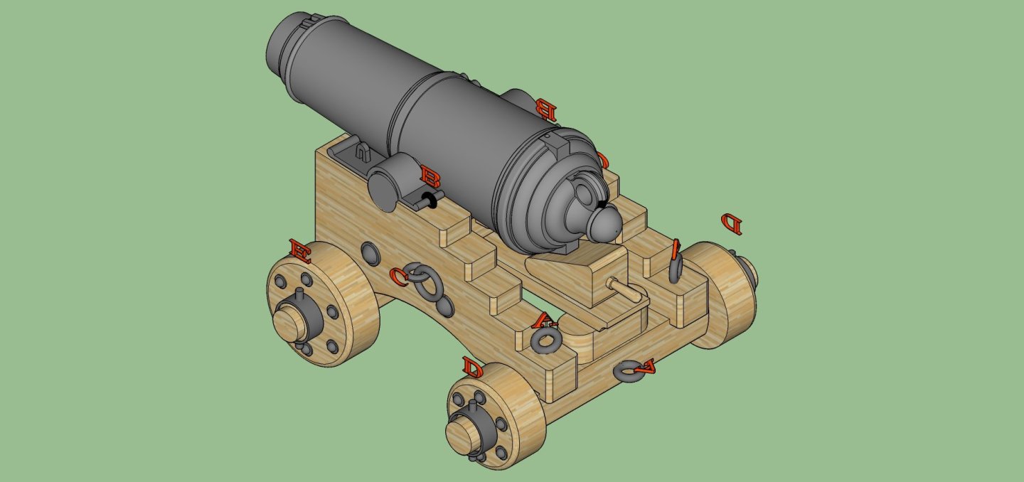
- 131 replies
-
- 10
-
-
Quality of Model Shipways Skipjack Ship
thibaultron replied to acaron41120's topic in Wood ship model kits
Their Skipjack kit is (in my opinion) the best on the market! The MS kit is of a "Standard" type. If, in the future, you are interested in building another Skipjack, the Midwest kit is a good choice. The difference between them is that the Midwest kit is of an "Outlaw Skipjack". The Outlaw skipjacks were smaller faster boats used by captains of "Questionable Morals" to dredge during times that were outside the lawful ones, typically at night. Chappell has more information in one of his books. The Midwest kit matches the drawing in the book almost exactly. -
3D Printing Cannons in Resin
thibaultron replied to thibaultron's topic in 3D-Printing and Laser-Cutting.
OK, thanks! -
3D Printing Cannons in Resin
thibaultron replied to thibaultron's topic in 3D-Printing and Laser-Cutting.
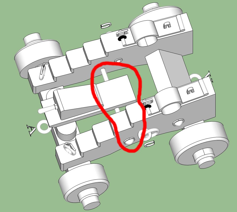
Got the locating pins in place. I now have to go through all the parts and validate the STL files. Then write up a PDF on assembling the carriage, and make the 2D drawings for the fabricated parts. Here is the exploded diagram of the parts. There are two sets of caps. The first (left hand set) has the hinge eyelet as part of the part, this simplifies the building of the carriage. The second (right hand set) has just an opening to use when fabricating the hinge eyelet separately.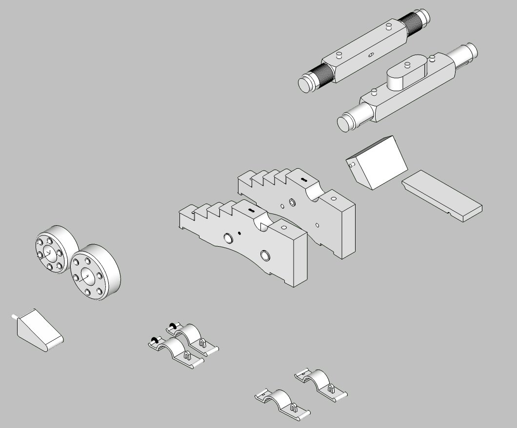
-
3D Printing Cannons in Resin
thibaultron replied to thibaultron's topic in 3D-Printing and Laser-Cutting.
Will Blender create mechanical precision drawings? Like to 3 decimal positions? If so, I may check it out. -
3D Printing Cannons in Resin
thibaultron replied to thibaultron's topic in 3D-Printing and Laser-Cutting.
Yes, I'm using SketchUp. I have an old loaded on the computer version. Because it is so old, I have been locked out of being able to load any of the extensions. So I am being very careful to not mess up my system drive, as I can no longer reload what I have. I'm thinking of going to either the subscription versions of either SketchUp or Fusion. Hate to spend the money though. -
3D Printing Cannons in Resin
thibaultron replied to thibaultron's topic in 3D-Printing and Laser-Cutting.
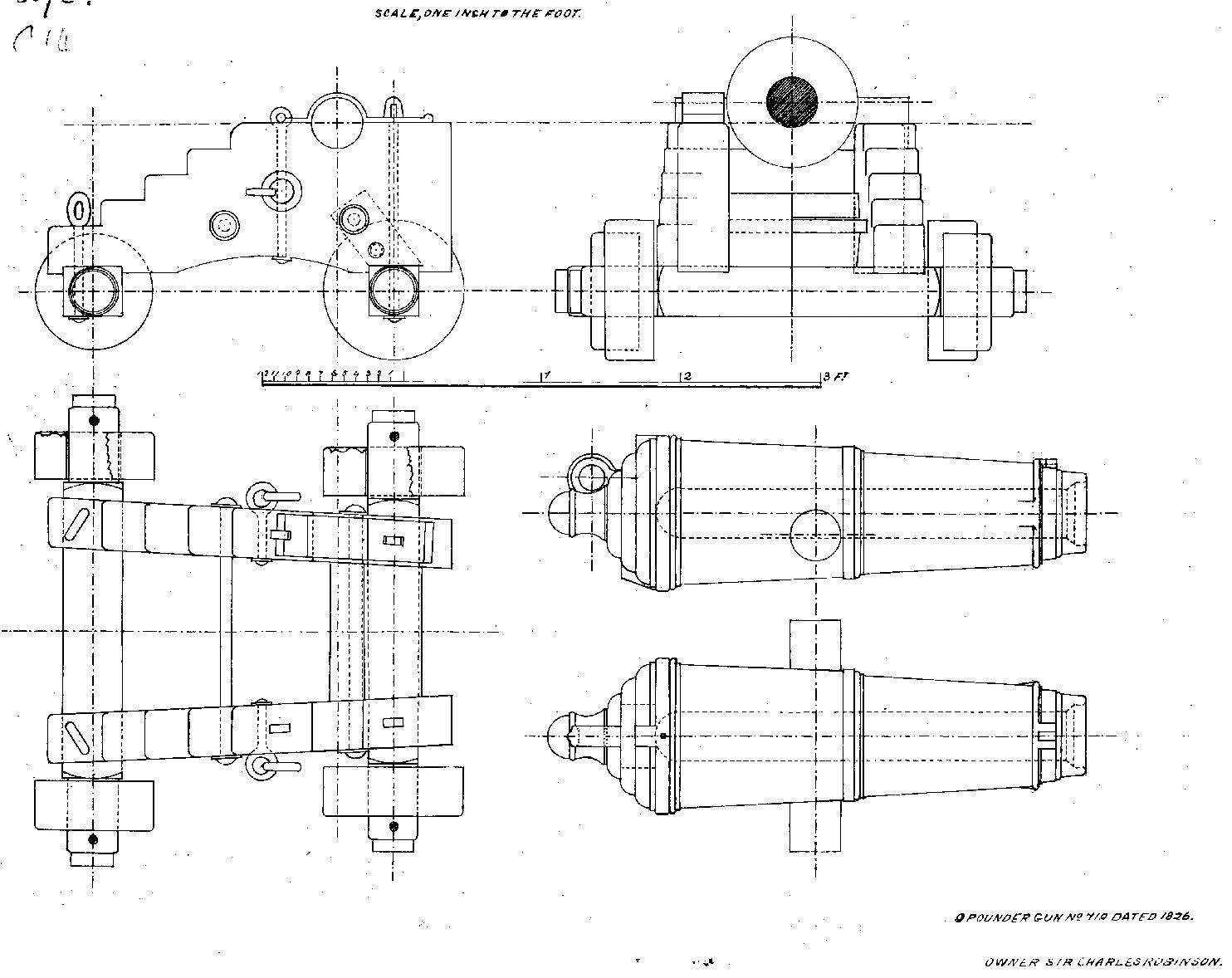
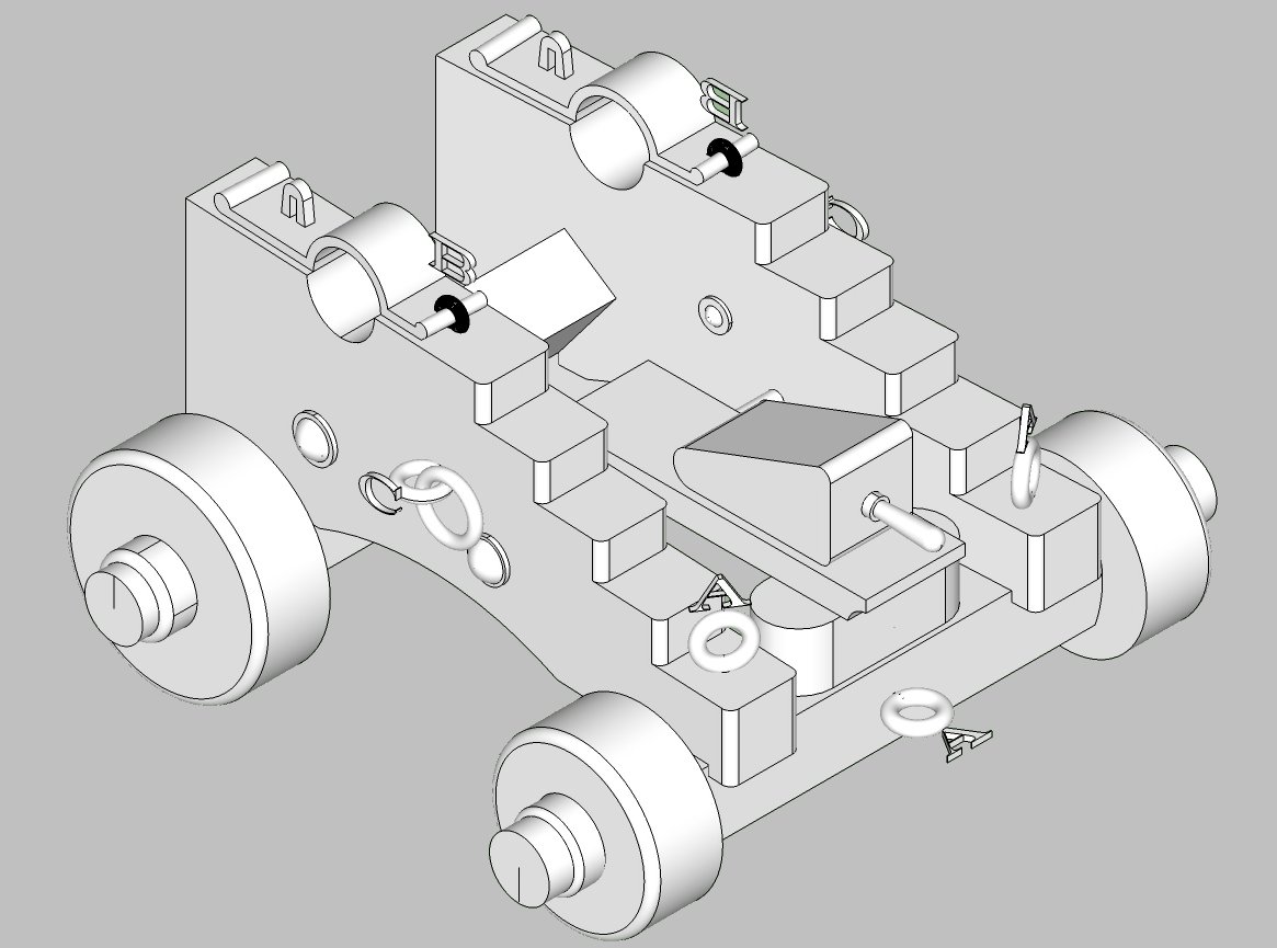
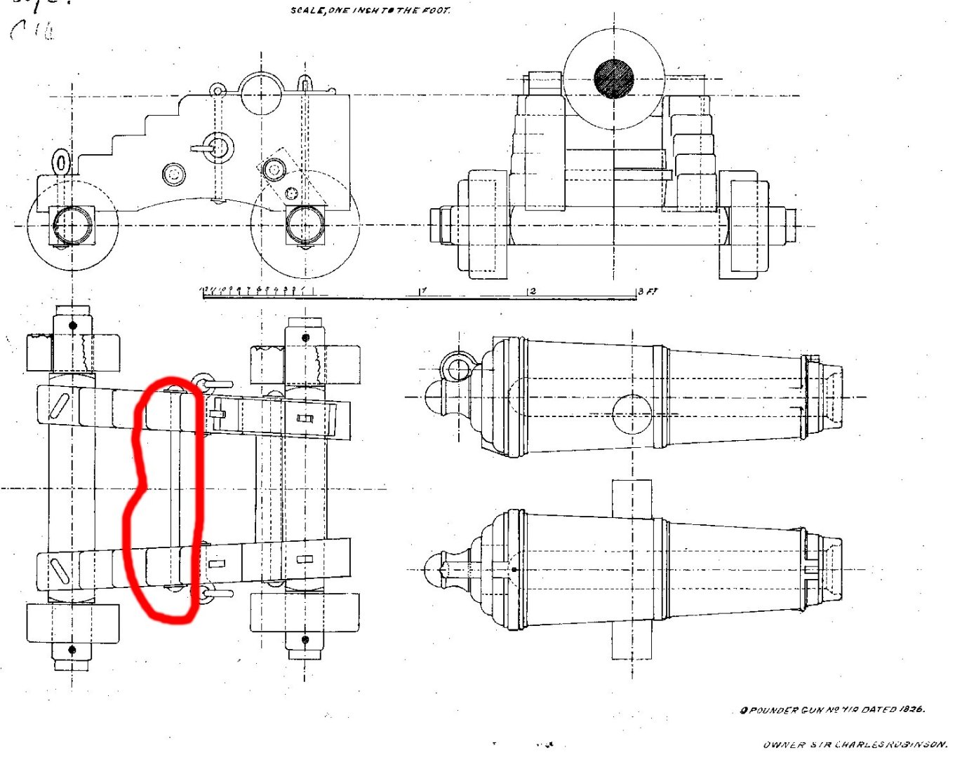
When I drew the Carronade with trunnions, I showed a few posts back, I used a drawing from 1826 to make it from. Well, I decided to try my hand at generating the carriage shown for it in the drawing. This drawing does not show the parts used to elevate the barrel. The Stool Bed, and the Quoin. I went through my library, and found drawings for a 32 Pounder in the Anatomy Of The Ship book on HMS Pandora. I rescaled the carriage drawings, and found the rescaled drawings to be quite close a match in length and height to fit the 9 Pounder (the carriage was wider rescaled, but a little math got me a scaled width for the parts). I used the drawings for the two parts as a basis for new ones. I also added eyes to the front and back of the carriage, as shown in the Pandora drawings. Here are a graphics of the carriage with and without the 9 pounder barrel. I still have to add locating holes and pins to the 3D drawing, before I generate the final 3D print files. I'll post them in a few days. The letters refer to wire eyelets that the modeler will have to make, I'll include drawings for them too. 3D printing them would be a nightmare, and the resin parts would be quite fragile. The modeler would also have to make the brass rings that hold the trucks to the axles. I'm going to have all the major parts as separate pieces, thus the need for locating pins. The Cap Squares (pieces that holds the cannon to the carriage have to be separate anyway to allow for the cannon to be installed). Should I, also, have an assembled (except for the cap squares, and truck rings) version? There is a through "bolt" that the front of the stool bed rests on that would be hard to print, in place, especially in smaller scales.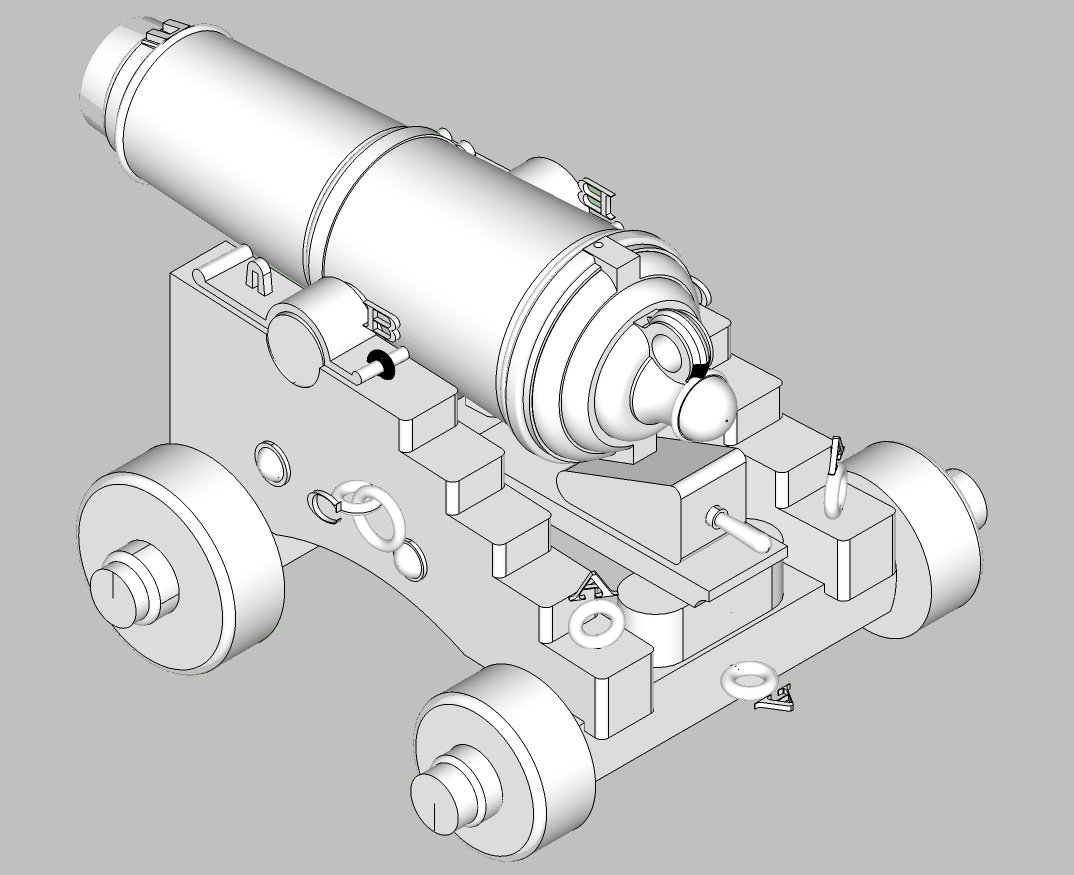

-
Cold War madness
thibaultron replied to Martes's topic in CAD and 3D Modelling/Drafting Plans with Software
Fantastic! -
Anime, yes, "Kiki's Delivery Service"
-
While a British ship the HMS Sultana was built in the colonies.
-
Fantastic work! One thing you might consider is carving out the edge of a plank to show one of each type of tenon in place, just for everyone to see the complete construction methods employed.