

igorcap
-
Posts
226 -
Joined
-
Last visited
Reputation Activity
-
 igorcap reacted to Kiyoo Iizawa in Making frame drawings and its adoption to laser cutting
It's been a while, everyone.
I have introduced here my original drafting method, but I myself did not verify the authenticity of the design yet except for a partial cross-section model. The full model requires more than four times as many parts to be assembled as the cross section, and if there are any mistakes in this method, I cannot recommend it to you.
To validate this method, I completed the design of the full model in parallel with the introduction of the method, and all of its parts were laser cut, and its assembly was started. The model is GRANADO 1/64 scale.
The results were more successful than I had expected, and the model was completed with more than seven hundred kinds and over 1500 parts. All were assembled exactly in place with only the laser burn-mark to be removed.
Shade also can create 3D printed data, and by utilizing this, GRANADO's mortar, cannon, and swivel gun are also made in accurate scale and assembled.
I think if this method spreads, even structural models will be able to be shared as an assembled set, like a bulkhead kit.
I would appreciate it if anyone who has obtained a manual can let me know the impressions of this method by even PM.
Thanks,
Kiyoo Iizawa
-
igorcap reacted to Kiyoo Iizawa in Making frame drawings and its adoption to laser cutting
7. Closing
By verifying the effectiveness of this new method with the above-mentioned way and I could produce the final set of design drawings and laser-cutting drawings after several trials.
The model design utilized the power of the software, I could add many structural parts drawings other than frame parts. In addition to further reducing the cumbersome work of conventional drawing creation, laser cutting in this method also enabled reduction of material costs and significant reduction of trimming and fairing time.
In order to share this effective technique with many people, especially beginner builders who want to challenge scratch builds, I am preparing a step-by-step procedure manual " Preparation of design drawings and the new part fabrication way in structural models ". It consists of nearly 180 pages of text, over 130 picture files, and a number of design sample files.
This also includes design data for GRANADO designed as a prototype and data for laser cutting.
If you bookmaking the manual part like below by yourself, I am sure it will help your learning effectively.
When you are going to apply this method, it may seem to you that investing in software is costly. All of the software I have actually raised here is a well-known subscription software and they are relatively higher price. Certainly, an initial investment in case it is done by an individual may become nearly equivalent to a power tool to buy. However, the design and fabrication benefits that this method provides are immeasurable, including the reduction of creation time. Moreover, once these data have been made, a lot of people can share them like I am doing now. Thus the total cost per person can be comprehensively reduced.
I have designed more than ten models frame data ever by using old version of this method and so far, it is used by many people in Japan. Creating the beautiful hull curved surfaces and the part drawings that make them up is just as fun as building a model.
In the last, I can say that by mastering this method,
You can design your own ship models and prepare the necessary drawings with the many flexibility.
You can accurately cut the necessary parts by yourself within a noticeably short time!
These are a lot of time saving at the preparation period and finally you can concentrate to your scratch model building!
I am now going to store the procedure manual files on the cloud storage etc. so that it can be shared with the MSW member who want to learn the procedure and/or use this method. It is not a commercial purpose.
Please send PM to me for the proposal. Then I give the key to download them. I hope this action will not be violate the MSW rules.
As I am refreshing the sentences of the manual now, please allow that it may take a while to upload them.
Thank you for reading through the introduction of my method and I hope that this method will enable many people to challenge scratch building.
Kiyoo Iizawa
A member of Yokohama Sailing ship Modelers Club (YSMC) in Yokohama, Japan
-
igorcap reacted to Kiyoo Iizawa in Making frame drawings and its adoption to laser cutting
Thank you for many comments.
Hi Mark P,
In fact, I have already prepared a step-by-step manual that explains the steps from learning software to actual creation work. It seems to be the best for learning this method. Please wait until I finish writing this topic on how to make it open.
Hi jaager,
This is an easy and much faster drawing method as you say to create accurate shapes at scaled size, correction drawings according to various processing machines, etc.
The number of lines for inside shape is as good as 10 when creating the outer shape. Actually, the lines drawn with the outer shape are copied and shifted the control point inward by the thickness according to the height.
In case the laser machine I am using in rental shop, the data machine recognize can still be used in Illustrator format. Therefore, there is no malfunction due to conversion. As far as I know, laser cutters seem to be able to use 2D graphics data such as Illustrator, CorelDraw, etc. as they are.
If this can be said to be a development product, I want to have ownership. However, the purpose of my posting on this topic is because I want anyone to use this technology openly. I think there are some things that need to be addressed for that. I'm old enough.
At first, I was skeptical about the use of lasers, especially for scratch builds, but since the advantages are much greater than the disadvantages, I put them to practical use after considering how to avoid the disadvantages.
Workarounds will be described soon in this topic.
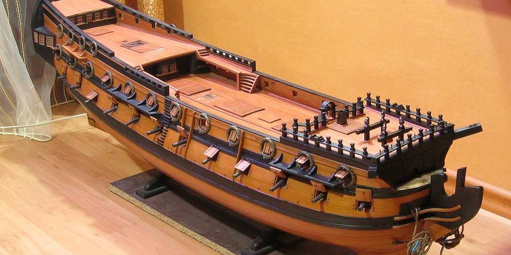
I actually designed a part equivalent to one structural model kit, processed it with laser cut, and am currently in building for verification. I have cut over 1,500pcs of parts within 8 hours. This picture is hull made parts by laser cut (just lightly sanded to remove burn mark). Also the cross section that took out some of it is my thumbnail.
To evaluate this method, please read this topic until it is over. I hope it will meet your expectations.
Hi PietFriet,
I have no knowledge of Delftship at all, but I think it can be used if it is software with similar functionality to the 3D graphics software I use. It is a free-form surface creation function by Bezier curve and numerical control function for dimensions and coordinates.
Thanks again,
Kiyoo
-
igorcap reacted to Kiyoo Iizawa in Making frame drawings and its adoption to laser cutting
1. Brief Introduction
The method introduced here is a system that (organically) combines 3D graphics software, 2D graphics software, and laser cutting machines to innovatively shorten drawings making and part machining in scratch builds.
First, to make the drawings for ship modeling, the most people are using CAD for drafting them but I see very few cases that it contains individual accurate frame drawings. In my case for several reasons, I am using the graphics software to make frame drawings as well as various parts drawings. The reasons are,
1) Many of the parts such as individual frames are consist of free line of shape which cannot easily be defined by numeric but the graphics software which I am using can rearise them accurately by one of its feature (Bezier curve etc.). The Bezier curve itself is vector data, it later plays a major role in creating the drawings.
2) 3D graphics software using Bezier curves can draw free curved surfaces with fewer line information and can be edited its shape intuitively and smoothly within a short time.
3) In this software, once a curved surface has been created, you can generate new line shape (rather than drawn) by slightly drag the desired location. This line can be used as a new frame line.
The first figure below is the line shapes of the Body Plan drawn in this software and the second figure shows hull curved surface generated from these line shapes. The third figure shows the generated new frame lines on the hull surface and the fourth figure shows their individual line shapes.
Cont.
Kiyoo Iizawa
-
igorcap reacted to Kiyoo Iizawa in Making frame drawings and its adoption to laser cutting
Hello everyone,
I am posting for the first time. Please forgive me for my uncertain English.
With regard to creating the precise 3D graphics images, I am far from Denis's amazing graphics in Swan class 3D modeling. However, using a similar 3D graphics software, my attempt here is to create line data, i.e. frame drawings, from that 3D curved surface.
Many 3D graphics software output formats are raster data, i.e. gathering of the small dots, but drawings such as CAD we use for part machining are consisting of vector data, i.e. line shapes represented by mathematical formulas. They are not compatible because they are completely different data.
But looking at the graphics image like below, wouldn't you wish to make each shape of this frame to an accurate drawings? It is the software that I am using that enables it. In other topics such as “JPG to CAD” are also being discussed this kinds of matter, but I think this method introducing here is also one of the way to do it.
If such an indefinite shape can be made into an accurate drawings, it is expected that drawings making and parts processing in scratch build will become much easier.
I would like to introduce the outline of this method by continuous posting. I wish you will be interested in this approach.
Because it is difficult for me to provide instant English sentence according to the situation, I am preparing outline description as a document. To identify the document part and the daily conversation, I use document text with green color so that you can easily pick up only the document part.
-
 igorcap got a reaction from ed w in Lanterns. Practical use of 3D technologies
I received an order to make parts for the assembly of lanterns for a 3-deck French ship of the late 17th century. First, a 3D project was made. Then the transparent resin inserts were printed. The lid and base were first printed out of resin, then wax-ups were made from them, and finally a brass casting.
You just have to glue the grid of wires and brass strips
-
 igorcap got a reaction from Archi in Lanterns. Practical use of 3D technologies
I received an order to make parts for the assembly of lanterns for a 3-deck French ship of the late 17th century. First, a 3D project was made. Then the transparent resin inserts were printed. The lid and base were first printed out of resin, then wax-ups were made from them, and finally a brass casting.
You just have to glue the grid of wires and brass strips
-

 igorcap got a reaction from Mldixon in Lanterns. Practical use of 3D technologies
I received an order to make parts for the assembly of lanterns for a 3-deck French ship of the late 17th century. First, a 3D project was made. Then the transparent resin inserts were printed. The lid and base were first printed out of resin, then wax-ups were made from them, and finally a brass casting.
You just have to glue the grid of wires and brass strips
-
 igorcap got a reaction from popeye2sea in Lanterns. Practical use of 3D technologies
I received an order to make parts for the assembly of lanterns for a 3-deck French ship of the late 17th century. First, a 3D project was made. Then the transparent resin inserts were printed. The lid and base were first printed out of resin, then wax-ups were made from them, and finally a brass casting.
You just have to glue the grid of wires and brass strips
-
 igorcap got a reaction from tlevine in Lanterns. Practical use of 3D technologies
I received an order to make parts for the assembly of lanterns for a 3-deck French ship of the late 17th century. First, a 3D project was made. Then the transparent resin inserts were printed. The lid and base were first printed out of resin, then wax-ups were made from them, and finally a brass casting.
You just have to glue the grid of wires and brass strips
-
 igorcap got a reaction from mtaylor in Lanterns. Practical use of 3D technologies
I received an order to make parts for the assembly of lanterns for a 3-deck French ship of the late 17th century. First, a 3D project was made. Then the transparent resin inserts were printed. The lid and base were first printed out of resin, then wax-ups were made from them, and finally a brass casting.
You just have to glue the grid of wires and brass strips
-
 igorcap got a reaction from archnav in Lanterns. Practical use of 3D technologies
I received an order to make parts for the assembly of lanterns for a 3-deck French ship of the late 17th century. First, a 3D project was made. Then the transparent resin inserts were printed. The lid and base were first printed out of resin, then wax-ups were made from them, and finally a brass casting.
You just have to glue the grid of wires and brass strips
-
igorcap reacted to Nek0 in Le Soleil Royal by Nek0 - 1/72 - Marc Yeu
Thank you very much for your messages !
Julia is growing up and will turn 1 year in a few days, it's been a very busy year between the family and the Covid but I could resume the work on the model a few days ago and I ended the third deck panels. I won't give up !
Thank you for your support, I really appreciate it !
-
igorcap reacted to WalrusGuy in USF Confederacy 1778 by WalrusGuy - Model Shipways - 1:64
Hi Wahka, the planking is still going slow and steady 😁. I was actually going to wait till planking above the wales is finished to post an update. But this may be a perfect time to update the log since I just finished planking till the top of the first row of gun ports.
Here are some pics after roughly sanding:
I also encountered a bit of a problem, not sure how bad it would affect the build later on.. I noticed the planking midship is not very symmetric. The sheaves in this location are very symmetric (I measured from the top of the rail and both sides have the same distances). So planking midship starboard side appear to be higher than the portside. Here is a pic showing what I mean:
Portside:
Starboard:
You can also kind of see this in the planks just below the gun ports. The spacing in the starboard side is smaller than the portside
I have no idea how this happened since the initial plank run was symmetric (or perhaps I measured wrong!). Maybe this is not too big of a deal and I am overthinking it, so let's see what happens! Any input would also be appreciated 🙂
-
igorcap got a reaction from Archi in Figurehead of the USS Confederacy (1778)
Decor set for USS Confederacy (1778). Now in the wood (pear). Scale 1/64
-
-
 igorcap got a reaction from scrubbyj427 in Figurehead of the USS Confederacy (1778)
Decor set for USS Confederacy (1778). Now in the wood (pear). Scale 1/64
-
 igorcap got a reaction from dvm27 in Figurehead of the USS Confederacy (1778)
Decor set for USS Confederacy (1778). Now in the wood (pear). Scale 1/64
-
 igorcap got a reaction from VTHokiEE in Figurehead of the USS Confederacy (1778)
Decor set for USS Confederacy (1778). Now in the wood (pear). Scale 1/64
-
.thumb.jpg.62d1d69fed1f32364417cb1f9cdeb009.jpg) igorcap got a reaction from WalrusGuy in Figurehead of the USS Confederacy (1778)
igorcap got a reaction from WalrusGuy in Figurehead of the USS Confederacy (1778)
Decor set for USS Confederacy (1778). Now in the wood (pear). Scale 1/64
-
igorcap got a reaction from mtaylor in Figurehead of the USS Confederacy (1778)
Decor set for USS Confederacy (1778). Now in the wood (pear). Scale 1/64
-
 igorcap got a reaction from JohnB40 in Figurehead of the USS Confederacy (1778)
Decor set for USS Confederacy (1778). Now in the wood (pear). Scale 1/64
-
igorcap got a reaction from scrubbyj427 in Figurehead of the USS Confederacy (1778)
The rest of the decor
-
igorcap got a reaction from JohnB40 in Figurehead of the USS Confederacy (1778)
The rest of the decor
-
igorcap got a reaction from mtaylor in Figurehead of the USS Confederacy (1778)
The rest of the decor