
MORE HANDBOOKS ARE ON THEIR WAY! We will let you know when they get here.
×


robnbill
-
Posts
841 -
Joined
-
Last visited
Reputation Activity
-

 robnbill reacted to popeye2sea in USS Constitution by Modeler12 - FINISHED - Model Shipways
I posted these somewhere else, but I do not know where. I thought these would illustrate the construction of the bentnik shrouds pretty well.
-
 robnbill got a reaction from Modeler12 in USS Constitution by Modeler12 - FINISHED - Model Shipways
Hi Jay,
I hope you had a relaxing vacation. While you were away, I looked at this in much detail. The way the Connie is currently rigged seems like a combination of "Best Practices" The futtock shrouds are carried down to a futtock stave. Together they are lashed to the lower shrouds. There are a few catharpins running between the shrouds. However, in addition, lines are also running from each of the stave from each shroud down to the ring of the Bentnick Shroud.. This is just on the Fore and Main. The photos I find of the mizzen do not show this.
The question then becomes was this a configuration which would have been possible, or probable during the 1812 action. The history of the Bentnick shroud goes back to the 1700's when it was invented by William Bentnick. These were introduced into the British Navy in the late 1700s. Since Joshua Humphery's and Captain Hull, would know of these practices, it would be entirely possible for them to be in the Connie's configuration during the battle.
I was able to find these in the rigging plans from a 1906 Navy Plan. Initially the shrouds were used to relieve pressure on the shrouds during heavy weather. However, during battle these would also assist in retaining the upper masts as the lower shrouds were damaged during a battle.
So given that the technology was widespread prior to the Connie being built and that her class was an amalgam of best practices in the design, I think it was entirely possible that the configuration then being much as we see today on the Connie. So that is how I plan on building her.
-
robnbill reacted to Modeler12 in USS Constitution by Modeler12 - FINISHED - Model Shipways
I just got back from a week vacation, but here is my understanding about what you are referring to:
The catharpins were used to tie the upper shrouds (coming from the topmast and down through the 'top') to the main shrouds. However, it was better to distribute the load on those shrouds to the other side. Hence, these lines did just that. I know this is confusing to read and that is why Petersson's pictures are so much better.
But the upshot is that if there are only five upper shrouds, you only need five catharpins. I don't know this for a fact, but I would assume they are tied to the forward shrouds (all others are too far aft). You take it from there???!!!
The Bentnick shrouds were a bit more complicated in-that they took the load on the upper shrouds down to the deck (instead of going across to the other shrouds). I don't believe Petersson's book shows that.
Then there is a third way and that was to tie the upper shrouds (below the 'top') to the main shrouds. This eliminates the catharpins and bentnick shrouds, but that puts all of the load on the main shrouds. And that is not fair???!!!
-
 robnbill got a reaction from tasmanian in USS Constitution by robnbill (Bill) - FINISHED - Mamoli - 1:93 kit - First Build - Bashed
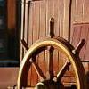
I completed the deck furniture today. I went off plan for a couple of areas. First the plan showed a pastil green skylight just forward of the ship's wheel. None of the books or other modelers had this. It has a hatch, so I used a small piece of left over grating and framed in a hatch. There were no binnacles in the plan. So I built two and pined them to the deck just forward of the wheel.
The wheel in the kit was mostly metal with the center hub having two small wooden rings to make the cylinder. The holes in the wheels were not the correct size so I drilled these out. I put the wheel together last night so it was set this morning. I painted it a darker brown and added tan to the handle spokes and the center of the hubs where the star is on the ship.
I shaped the stern davits and glued them into place. I added the chain boards to each side. I did not add the outboard strip since I will need to be able to put the chains in before I add them.
After consulting with Mort Stoll, I found out the ship's kit did not include the blocks to rig the cannon. I really want to rig the cannon. So I ordered 100 ea 2.5 single and double blocks (Syren Ship Model Co) as well as a roll of brass wire so I can make the rings and hooks. I know Chuck shipped the blocks today. In the meantime, I plan on starting tapering and assembling the masts. I ordered a dowel support for my lathe. It is a full size lathe so it will be interesting trying to turn the small spindles. I did do the first section of the bow spirit and it seemed to work out well.
Attached is a photo taken from above showing the layout of the deck furniture. The extra black blocks on the side are real just the square holes in the workbench underneath. I still need to figure out a way to level the ship form side to side on the pedestals. I did get the taller pedestal installed today so the ship sits pretty level fore to aft.
I ran out of the kit supplied cannonballs today. The additional ones are back ordered and hopefully will be in soon.
-
robnbill got a reaction from tasmanian in USS Constitution by robnbill (Bill) - FINISHED - Mamoli - 1:93 kit - First Build - Bashed
I made more progress on the deck furniture today. I built both the capstan and skylight. The skylight in the kit consisted of a square base, a 6 sided plain base and a flat metal piece with the skylights imprinted on them. I did not like this. So after shaping the base to be equal sided, I used the rotary tool to inset the panels around the base. Then I carved the six sided top and used the rotary tool to inset where the glass would be. These I painted black.
The capstan had nothing in the plans other than a drawing with no dimensions. I pulled the Constitution plans for the capstan and used them to assist in shaping the 8 insets. The kit only supplied the spindle with the domed top and bottom. Since the real capstan has a brass top, I decided to paint mine black along with the lower band. Then the middle I stained.
I completed the deck assembles around all the hatches and installed the stairs and platform for the capstan. Then I glued everything up. I have not yet installed the Main and Mizzen fife rails, the ships wheel and skylight (small square one), and the various cannonball holders. These should all be completed tomorrow, I hope.
I also stained all of the blocks. After consulting the forum, I tried a number of different methods. First I tried to put the stain on a paper towel and roll the blocks in it. This was not satisfactory since it did not get the stain into the grooves. I tried dipping the blocks in the stain, then wiping them off on a towel. This worked but only for the larger blocks. The small ones would take forever to do this way and I would probably end up dropping one or more in the stain or on the floor. Finally for the small blocks, I put them all into a large spoon. Then used a dropper to add the stain. This allowed me to move the blocks around until they were all coated well. Then I raked them onto a paper towel and rubbed the excess stain off. No clean way of doing this but it is wall done.
Finally, I airbrushed a second coat of black onto all the cannon barrels. I also painted the carriages of the 24 pound bow chasers red. I planted the wheels black and glued them onto the carriages. Tomorrow, I will clean up the glue and sand the stairs and capstan where needed.
The skylight is placed but not glued in the photo. I will glue it up once I work my way back to the aft deck. One of the shots below shows a test placement of the forward cannons.
Overall, the ship was better tonight than it was this morning. A successful day.
Bill
-
robnbill got a reaction from tasmanian in USS Constitution by robnbill (Bill) - FINISHED - Mamoli - 1:93 kit - First Build - Bashed
I added a bit of black wash to the Eagle boards this morning. I believe it adds a bit of depth to the carvings. These are metal fittings from Mamoli. In addition, I completed the main hatch today. This was more complicated than it seemed initially. Given the deck camber and the many part to be cut and fitted, it took longer but I am pleased with the results. I modified the plans for the forward ladders. I ran them fore to aft rather than side to side. This is in line with the AOS. I led the midships side to side since the deck had a large opening already cut in it to allow for that. I also decided to paint the lower decks around the stairs the bulwark green. Since these really do not show and are left un-planked, this keeps them from looking unfinished and highlights the lighter stairs which are the feature that is important. I also painted the deck black under the forward small hatch since the deckle would have shown through the grates since these were basically right on top of the deck. I still have to mount the ships boat cradles but will do this a bit later.
Again, I think the ship is in better shape than it was when I started this morning so today was a success.
Bill
-
 robnbill got a reaction from schooner in USS Constitution by robnbill (Bill) - FINISHED - Mamoli - 1:93 kit - First Build - Bashed
Hull Paint Prep
Since I was painting the hull, I used spackle to smooth the hull and sanded using 220 grit. Once satisfied, I masked the hull at the waterline. Since the waterline was established when I put the faux copper plates on the hull, this was easy. I used standard masking tape at the waterline, then the blue tape to cover the rest of the hull.
I used a light pecan to stain the spar deck and left it to cure overnight.
Copper Bottom
Since this model uses a faux copper bottom I had to buy copper and green paint since these were not part of the Model Shipyards paint set for the Constitution. I took a green tile with me to the model store to match the color.
The instructions called for painting the hull below the waterline with copper paint. I airbrushed the copper on and once this dried, sanded it lightly to remove the paint in some areas to expose the wood and green paint below the copper. I used a microfiber cloth slightly dampened with Mineral Spirits to wipe the hull down. Then I airbrushed the green paint onto the hull and immediately used a soft cotton cloth to rub the green into the hull. I did this in overlapping sections since the paint needed to be wet when I rubbed it. This turned out great.
I removed the masking tape when the paint was dry then left it overnight to cure. I masked the hull below the waterline, as well as the spar deck and interior bulkheads up to, but not including the handrail.
Below is the Faux Copper bottom. The green plates have all been installed and lightly sanded on the hull.
From here on I used the model shipyards instructions on painting from their Constitution instructions. Unless otherwise noted, all paint was applied using an airbrush. I used the Model Shipways primer to paint all the exposed surfaces and lightly sanded after the second coat. Then painted the hull black. After the first coat, I cleaned up the base of the gallery where it still was a bit rough. Since I took the primer off the metal in doing this, I used a can of Tamiya primer to spot prime those areas. After a light sanding a applied two more coats of black letting the paint dry between each coat. After two coats I would let the paint cure overnight.
After the past paint cured overnight, I removed masked the hull to paint the gun port stripe. I debated priming again in that area but decided against that and chose instead to paint the white directly over the black. My current plans are to have the gun ports closed in the final model so I did not worry about white getting into the port.
With the paint curing, I used some time to take the assembled grates and sand them down to 2.5mm. When I assembled the grates I soaked them in water with wood glue. This seemed to set the grates but once I started working on thinning them I found the grates would not hold up. I used thin CA to re-glue the grates then once dried continued to sand them down to the correct thickness.
Once it dried 2 hours, I removed the masking tape on the outside of the hull. I did have to correct a bit of white overspray, but that was easy with the airbrush.
2/05/14
I thinned some white and black paint slightly but not as much as that needed to airbrush, the goal being to allow it to flow from a brush. I used this to paint the scrollwork on the bow with white. I used the black to correct any over brushing. This took a great deal of back and forth since my painting skills are not the best.
Once the bow was done, I painted the additional decorative details I added on the stern. This I allowed to dry overnight.
2/06/14
I touched up the white and black details all around.
I spent a good portion of the day removing the white metal columns, cleaning them up, priming and painting. I learned the hard way that these need to be cut from the casting armature. I broke one. The plans show the three lower stern windows have the two part plate with the cannon hole. I counted the plate pairs and there were just enough for the side cannons. However the book shows Anatomy of a Ship, shows these to be a one piece plate or at least no cannon hole with air ports at the top. There are port covers that are single covers with the ports in the top included in the plan. The plan was incorrect.
I also decided to go off plan and paint the Eagle Gold. I just think it looks great that way.
I used the sticky side of a small strip of masking tape to stick the small stars to so they could be primed and painted.
I realized after painting the stern nameplate white it needed to be black. Then after it dried I came back to paint the letters with white. Before painting I had to do quite a bit of thinning. I did this on all the white metal pieces. Otherwise they would be very bulky.
The windows in the stern are slightly large for the window plates so I thought I would glue the columns to each side of the plates prior to putting them on the stern. This did not work well and I ended up soaking them in acetone to remove the CA, then had to clean all the pieces over and repaint. I found on these pieces it was easier to use a 00 brush and paint them after they were attached to the hull.
After these were fitted and painted and the surrounding stern touched up with black, I fitted the Eagle. This required me cutting the lower of the double scrollwork above the Eagle. I looked at the photos and this is actually what seems to be on the real ship. I marked where the scroll needed to be removed and used a wood chisel to remove the portion under the Eagle. Then I painted the area black and let it dry.
The plans also called for the three port covers to be white. In reality they are black. I think it makes the columns stand out better. So I painted them black.
I fit the rudder to the hull and glued the hinges onto both. Prior to mounting the rudder on the hull I drilled the hole for the rudder chains to affix to the rudder. I dry fit the rudder then started adding the pins to the hinges from the bottom up. These proved challenging to find if they fell onto the floor (which they did several times). The hinges were the first part that I actually did not have enough to complete the assembly in the kit. I used a brass rod to make a 5th one. The ballpeen hammer and mini-anvil worked great to make a head on the pin. I touched up the faux copper bottom and the rudder hinges. Then I glued the rudder into position. After the rudder glue set, I added the chains to the stern. I still need to go back to the bow and touch up/smooth the scrollwork paint.
Okay, this gets things caught up. Only 22 years to get to this point!
-
 robnbill got a reaction from JohnOz in USS Constitution by robnbill (Bill) - FINISHED - Mamoli - 1:93 kit - First Build - Bashed
Bow
I used 3x1.5mm walnut strips and 2x1.5 basswood to created beams for the bow construction. I decided to construct beams which were already U shaped so I could make the scroll work stand out. Given the smaller scale of the Mamoli kit I did not feel I could just use paint to smoothly to add the double stripes. By using the 1.5mm strips I could construct beams curved to fit the bow as well as straight beams that I could shape with the file for the 5 vertical beams.
The first thing I did was take the white metal fiddle plates and shaped them to fit the bow. These required significant thinning before adding to the bow. The plan called for using 9 strips walnut to create the piece that connected the fiddlehead plates to the bow. I did not like this arrangement. The instructions were also very sparse on the shape of these pieces/ Instead I took a small piece of pine and shaped two pieces that would fit the bow leaving just enough room to add walnut planking on the three exposed sides. This also allowed me to extend the top and bottom plates in a similar method as the other scrollwork.
The method worked pretty well. I was able to glue the beams to the hull using CA glue and using the bending iron to set up the glue quickly. This also allowed me to add more or less curves as I glued them to the bow. This was critical to make sure the two sides mirrored each other when viewed from the bow.
Hull
The kit only included the strakes outside the hull just below the waist and below the gun ports the full length. I added the strakes above the gunports as well based upon other models as well as a review of the available plans.
I liked the look when they were added. Since I was painting the hull, I also could use basswood (I acquired from the local RC Model shop) to make the strakes rather than matching the walnut.
On the interior, I added the strakes but choose not to follow the plan and add the 4 fittings, the belying pin racks and the line blocks on the forward bulkhead since they were to be stained. I also added the molding strip where the sides met the deck.
Cathead
Placement of the forward cathead was very sketchy in the plans. I used tracing paper to sketch the angle of the cathead rom the centerline. Then I estimated the angle needed for the cathead to end up 2mm above the spar deck where it penetrated the deck. There was a shaped piece that was added under each of the catheads the mount it to the deck. The key was it needed to enter just above the coming. I used an adjustable square to catch the angle from the tracing paper. Then place the square along the centerline of the deck and marked the place it crossed the handrail. Once both sides were marked and triple checked, I used a square to mark the side hull from this mark. Then I scribed a line where the cathead needed to be when it penetrated the inner bulkhead. I used the plans to guesstimate the slope and the difference (higher) the cathead would be when it exited the hull. This was the second line I scribed above the first line. This was the bottom of the cathead. Since the cathead is a 4x4mm, the actual entry point was 2mm above the second line.
I took a very small drill and chucked it into the power drill. I know that the advice I had received was to not use a power tool, but I am very comfortable with the drill and using it allowed me to easily adjust the holes once they were drilled. Used the two marks as my guide and slowly more the hole through the hull on both sides. I added a small drop of CA to both holes to keep the walnut from splintering. The cathead came through the forward bulkhead and it was very thin. Once the glue was dry, I gradually increased the size of the holes until I could stick toothpicks into both. This allowed me to adjust each to mirror each other as well as being the correct angles.
Once I was satisfied with the placement, I continued to increase the drill diameter until the holes were slightly smaller than the 4mm required. Then I took a brand new Xacto blade (the thin pointed one) and used it to carve both the entry and exit holes square and fitted the catheads through the hull.
Lastly, I carved the small blocks that were the base of the cathead on the deck.
I performed a final review of one cathead then glued it in place with CA. Then I did a final adjustment of the second cathead to mirror the first one. The goal was to get both very close, then exactly match the placement of the second to the first. This would keep any errors from being readily apparent when viewed.
The photos below show the final position of the catheads. The bottom one showing the mounts where the catheads mount on the spar deck.
-
robnbill reacted to Erebus and Terror in THE BLACKEN-IT TRIALS
The Problem:
Anyone who has followed my HMS Terror scratch build may remember my issues with blackening brass fittings for the stern assembly. To briefly summarize, I immersed the parts in a standard 8:1 mixture of Blacken-It solution mixed with bottled water, waited until the parts turned the appropriate colour, then rinsed in bottled water to “neutralize” the reaction. I tried this several times on different parts and each time it resulted in a flaky, blotchy appearance that could not be made even despite buffing with a soft cloth.
Here is an image of my results. Note the blotchy and flaky texture.
Inspired by the fine results of other modellers on the boards, I resolved to master the “mysteries of the blue Liquid”. I began with research; modelers, gunsmiths, jewellers, instrument makers, and mechanics all use various products and processes to chemically blacken metals and a great deal of information is available from forums, blogs, websites, magazines, and books.
With this knowledge at hand, I decided to conduct a series of trials to determine the best process for blackening metal using Blacken-it. I chose Blacken-it as it seems to be the most commonly used product on Model Ship World, and, perhaps more importantly, I had a supply available. However, the techniques I use here should be applicable to other metal blackening products.
Before I outline my tests I should begin with a note on safety:
The chemicals used in the blackening process are dangerous. Rubber gloves, safety goggles, and a well-ventilated room (or fume hood) must be used EVERY time you handle the chemicals.
The Process:
From my research, I learned that producing consistently good results requires seven steps, in this order:
1) The surface of the metal should be mechanically prepared. This roughens the surface and removes synthetic coatings that are often used to give stock metal a shiny appearance.
2) The surface of the metal should be treated with an acid pickle to remove any scale or corrosion.
3) The metal should be cleaned with a solvent to remove organic contaminants such as oils, fingerprints, and other dirt.
4) The metal is chemically coloured using a diluted blackening agent.
5) The reaction should be “fixed” or halted, using a neutralizing solution.
6) The surface of the metal should be buffed to remove excess blackening products and to polish the new surface.
7) The metal should be coated in a protective agent to prevent corrosion, soiling, and damage (optional).
The Equipment:
My research indicates that the following chemicals most often produce consistent results:
1) Muriatic acid (31.4%). This is commonly used to remove scale and corrosion on the surface of the metal. Most hobbyists and professionals use 1:1 concentration of water and acid. Remember, you should always pour the acid into water, as it can be dangerous to pour water directly into acid. You can purchase muriatic acid in most hardware or pool supply stores.
2) Deionized water. This tip was given to me by Druxy on these forums. I’m convinced that the blotchy, scaly results on my first use of Blacken-it were the result of my use of mineral-laiden bottled water. Dionized water is treated to remove mineral ions which could react with Blacken-it. Use the deionised water for all stages of the blackening process, including rinsing between baths, diluting chemicals, and for neutralization.
3) Acetone (100%). This is a widely used degreasing agent employed to remove finger prints, oils, or other organic coatings which might contaminate the metal. It can be purchased at any hardware store.
4) Baking soda. The final stage of the blackening process should include proper neutralization. A common solution is two table-spoons of baking soda in a cup (250 ml) of warm deionised water. Often, hobbyists will use running tap water to neutralize the reaction with good results; baking soda seems to be preferred by jewelers and instrument makers.
Here is a photo of the equipment I used in my tests.
The Tests:
My trials involved testing two variables: 1) the concentration of Blacken-It (undiluted, 1:1, 5:1, or 10:1), and 2) water neutralization versus baking soda neutralization.
The test parts prior to preparation.
Step 1: I thoroughly sanded the surface of my brass test parts with 400 grit sandpaper. This is similar to the preparation of any metal part even if it isn’t going to be painted or chemically coloured.
Step 2: I buffed the metal with ultrafine steel wool. Be certain to carefully remove any steel wool filings that remain as they can react with the chemicals used in the next stages.
The parts after mechanical preparation.
Step 3: Immerse the part in muriatic acid (diluted 1:1 with deionised) water for 30 minutes. You can immerse the parts for longer, but the acid will eventually etch the surface and soften sharp edges and other details if you leave them in too long. You may notice that the pickle will change the colour of the brass or that some corrosion may appear – this is normal and is caused by impurities or inconsistencies in the metal.
Step 4: Rinse each part by agitating vigorously in a bath of deionized water for at least 10 seconds. Allow to dry thoroughly on a clean paper towel. Change the water in the bath for the next step.
Allow the parts to dry thoroughly.
Step 5: Immerse the parts in an acetone bath for 30 minutes.
Step 6: Rinse each part by agitating vigorously in a bath of deionized water for at least 10 seconds. Allow to dry thoroughly on a clean paper towel.
Allow the parts to dry thoroughly.
Step 7: Immerse the parts in the Blacken-it solution. Maximize the surface area of the part exposed to the chemical by placing it on end if you can. Gently, without scratching the surface, turn the part every few minutes to ensure all surfaces are exposed equally to the solution. Carefully monitor colour changes, and remove the part when the desired colour is achieved.
Different concentrations of Blacken-it.
The parts after 30 seconds.
After five minutes.
After 60 minutes (other parts removed when desired colour achieved).
Step 8: Instantly dunk the part in the warm baking soda bath. Agitate vigorously for ten seconds. You will notice that the part will begin to corrode and a blotchy green or red film will cover the surface. Do not worry.
After a bath in the baking soda solution, the part will appear green (or sometimes red).
Neutralizing with water leaves a cleaner surface (but caution is warranted, see below).
Step 8: Carefully buff the part with a clean soft cloth (an old t-shirt works perfectly). Do not touch the part with your fingers. You will notice that the corrosion products resulting from the neutralizing bath will scrub away. Buff until all portions of the part have an even colour; continue to buff if you want a shinier surface.
Buffing the parts fixed in the baking soda solution removes the green/red coating.
After buffing, all the parts appear roughly similar in colour and finish from a distance (see below for differences).
Step 9: Wait 24 hours to ensure the reaction was effectively neutralized. If “sweating” or pitting is noticed, the reaction was not properly neutralized, and a further rinse may be required. Usually the part can be salvaged by buffing with a soft cloth. Sometimes, it may need to be blackened again.
Step 10 (Optional): Spray the parts with a thin acrylic matte coating to protect the surface.
I use Krylon Matte Coat.
The Trial Results:
Undiluted Blacken-It solution:
The undiluted solution produced a very dark, but somewhat uneven black surface in about five minutes. Fixing the reaction with baking soda caused a significant amount of corrosion, but it was mostly removed by buffing.
Undiluted immediately after buffing.
However, after 24 hours both parts began to sweat, indicating that the chemical reaction had not been neutralized even with a baking soda bath. This is not unexpected, as the product guidelines indicate that the product is meant to be diluted.
Undiluted after 24 hours.
Recommendation: Do not use undiluted solution.
1:1 Blacken-it Solution
This is the concentration recommended by the manufacturer. After ca. 10 minutes the part reached a deep black, but after neutralization with baking soda solution the surface appeared to be quite blotchy. After 24 hours the edges of the part began to sweat and corrode and the surface appeared pitted.
1:1 immediately after buffing.
1:1 after 24 hours.
The water neutralized part had a slightly more even surface, but unfortunately began to sweat after only 24 hours.
1:1 unfixed (water neutralization) after 24 hours.
Recommendation: Do not use 1:1 solution.
5:1 Blacken-it Solution
The 5:1 solution required approximately 25 minutes to reach a deep black. Immersion in the baking soda solution initially produced a green corrosion but buffing resulted in an even black surface. The part remained stable after 24 hours (and is still stable a week later).
5:1 immediately after buffing.
5:1 after 24 hours.
The unfixed, water-neutralized part began to corrode at the edges after 24 hours.
5:1 unfixed immediately after buffing.
5:1 unfixed after 24 hours.
Recommendation: Works very well in conjunction with a baking soda rinse.
10:1 Blacken-it Solution
The 10:1 solution required approximately 60 minutes to reach a dark even black. Immersion in a baking soda rinse produced a slight corrosion, but buffing resulted in a very even and deep black surface (in my opinion better than the 5:1 concentration). The part has remained stable after a week.
10:1 immediately after buffing.
10:1 after 24 hours.
Similar results were achieved with the water-only neutralization, and the part remained stable after 24 hours. However, after ca. four days corrosion began to appear at the edges of the part.
10:1 unfixed after four days.
Recommendation: The 10:1 solution performed very well in conjunction with a baking soda rinse, and in my opinion produced the best colour and surface.
Final thoughts:
1) Fixing the parts by agitation in a warm baking soda bath appears to be a critical step in blackening brass, at least with Blacken-it. Even at lowest concentrations, and with a water-neutralizing rinse, the acidic reaction appeared to continue for some time, especially around edges and in nooks and crannies.
2) 5:1 and 10:1 solutions appear to produce relatively similar results, even though they both require proper neutralization. The 10:1 solution appears to produce a slightly more even and deeper colour. Using Blacken-it at its recommended concentration is a waste of product and results in corrosion even after proper neutralization.
3) Buffing is a critical step in achieving the proper surface appearance.
4) I was able to rejuvenate “sweating” parts by dunking them in a baking soda solution and then buffing. Regardless, faint hints of the corrosion remained.
-
robnbill reacted to Modeler12 in USS Constitution by Modeler12 - FINISHED - Model Shipways
Henry, there is another possibility. The ship did not always have the bentnick shrouds, I am sure. The book by Marquardt 'Anatomy of the Ship . . .USS Constitution' shows a drawing of the futtock area that is much more like most ships of that era. This is part of page 102. Notice item 6.
Of course, I have no idea when the change took place.
-
robnbill got a reaction from tasmanian in USS Constitution by robnbill (Bill) - FINISHED - Mamoli - 1:93 kit - First Build - Bashed
So I completed the spars today! Now on to the rigging. Sorry the photos did not come out better but I arranged them on the butcher paper that I used to paint them on. Starting top right is the Spirit Sail Spar, below that are the forward mast Spars. The main mast spars are the set in the middle. The left most set are the mizzen mast with the two spanker spars above them.
-
 robnbill got a reaction from MarisStella.hr in USS Constitution by robnbill (Bill) - FINISHED - Mamoli - 1:93 kit - First Build - Bashed
So I completed the spars today! Now on to the rigging. Sorry the photos did not come out better but I arranged them on the butcher paper that I used to paint them on. Starting top right is the Spirit Sail Spar, below that are the forward mast Spars. The main mast spars are the set in the middle. The left most set are the mizzen mast with the two spanker spars above them.
-
 robnbill got a reaction from Cuda1949 in USS Constitution by robnbill (Bill) - FINISHED - Mamoli - 1:93 kit - First Build - Bashed
The Mamoli plans had the launch tied down over the main hatch literally with the line just being knotted together at the deck. I did not like that so I created a loop in each end and seized them and used two of the double blocks I used on the cannon rigging to create a block and tackle set with hooks on each end. These then hooked into the loops and cinched the line down. I coiled the remainder of the line up underneath the launch after tying the lines off with two half hitches. I like this better and it seemed a good solution.
I also started putting in the chain plates. First I enlarged the chain plate channel holes to be large enough to accept the chain plates. I did this to all of them. Then I installed the chain plates for the port side foremast. I have the starboard side inserted but not yet mounted to the hull. Progress is good.
Bill
-
 robnbill got a reaction from HIPEXEC in Mamoli's USS Constitution
Apparently 300k deeper if the guy on eBay get's what he is asking for!
All great ideas. However, I did like how the green panels turned out for the bottom on mine.
-
robnbill got a reaction from HIPEXEC in Mamoli's USS Constitution
It is the position for the secondary anchor storage.
-
 robnbill got a reaction from Aussie048 in USS Constitution by robnbill (Bill) - FINISHED - Mamoli - 1:93 kit - First Build - Bashed
Today I created the swivel stun assail boom attachments and attached them to the ship. The plan called for using rings on the end of the stun sails and to mount them on hooks attached to the hull. The real ship has pins in the stun sail booms bent at 90 degrees and these stick through mounts attached to the channel. It also needs to have a bracket made to hold the end of the boom for the forward booms. The rear booms tie to the channels. I used some brass channel pieces and some small brass tubing. I cut the channels to length to mount on the forward side of the chain channels. To these, I soldered the small tube pieces. Then I ground the assembly down to shape it nicer than the raw channel. I sloped the sides of the channel down to the width of the tubes at the outer ends.
I used some brass strips to create the brackets to hold the forward boom ends. I soldered 1mm brass rods on the end of the upper bracket to insert into matching holes I drilled in the hull just above the wale. The lower bracket brace I bent upward and glued to the hull. Since the rear booms end up straddling the midships and stern channels, I just tied the stern end of the boom to the channel. I did not feel that a hook would be seen at all. Also, since these are painted black they tend to blend in with the hull. However, I do like the way the booms look attached to the hull. I think the brackets came out like I wanted them to.
I also have attached a photo of the four anchors sitting on the forward deck. Ready for installation.
-
robnbill got a reaction from HIPEXEC in USS Constitution by robnbill (Bill) - FINISHED - Mamoli - 1:93 kit - First Build - Bashed
The Mamoli plans had the launch tied down over the main hatch literally with the line just being knotted together at the deck. I did not like that so I created a loop in each end and seized them and used two of the double blocks I used on the cannon rigging to create a block and tackle set with hooks on each end. These then hooked into the loops and cinched the line down. I coiled the remainder of the line up underneath the launch after tying the lines off with two half hitches. I like this better and it seemed a good solution.
I also started putting in the chain plates. First I enlarged the chain plate channel holes to be large enough to accept the chain plates. I did this to all of them. Then I installed the chain plates for the port side foremast. I have the starboard side inserted but not yet mounted to the hull. Progress is good.
Bill
-
robnbill got a reaction from tasmanian in USS Constitution by robnbill (Bill) - FINISHED - Mamoli - 1:93 kit - First Build - Bashed
I have been remiss in updating my log, but have been actively working on the ship's 34' launch. As you know if you have ready this build log, I decided to build the ship's boats from scratch. Using plans for other ship's boats as a basis, I took the Anatomy of a Ship's hull lines for the 34' launch and used it to create the plans for the boat. I found that printing them at 118.5% gave me the actual size plans I needed. Also, if I printed the hull lines without any magnification, I was able to get the exact size I needed for the shapes allowing for the ribs and planking. So this is what I did.
I took .5mm strips of walnut and thinned them down to the rib size and soaked them in a 50% solution of ammonia water before shaping them to the forms and gluing the ends to each. Once all the forms had ribs on them, I attached them to a backing board so I could plank. I used walnut than planked the hull. After cutting it loose and cleaning it up, I added the inner hull details. First the deck strips, then the platforms at the bow and stern. I added the seats and stained the inside details.
I use the enlarged drawing to create the deck rails by cutting it out into two pieces and gluing it to the hull shell. Then I thinned it. I added the strip to create the oarlocks and the curved shaped to the bow and stern. Then I added rings where it seemed like they would be ended to rig the sails. I used forked toothpicks and bamboo skewers to create 14 oars stained them and bundled them into to groups of 7. This would be a full set of oars for the launch. I turned a mast that matched the step I put in the launch and also turned a spar for the lateen rigging. I added rings to the top of the mast for the two halyards. I also banded the mast just above the step and near where the spar would end up when sailing. I painted the ends of the mast and spar black.
I used one of the flat bamboo forked toothpicks to create the rudder. For the hinges I flattened brass wire and shaped it into two "U"s that fit the stern of the launch and the lower part of the rudder. I soldered these to a small pin before mounting it onto the launch. For the upper hinge, I used a small strip of flattened brass and soldered a pin to it and bent it 90 degrees and interred it into the rudder before gluing it onto the hull.
I did a final touch up of painting to the hull then did a test arrangement of the oars, mast, spar, and coil of rope. Once I was satisfied, I glued everything together and bound the launch to the cradle on the main deck.
Now my plans are to work on the chain plates and the lower dead eyes.
-
robnbill got a reaction from tasmanian in USS Constitution by robnbill (Bill) - FINISHED - Mamoli - 1:93 kit - First Build - Bashed
I started working on the ship's boats today. However, I also wanted to fix something that had been nagging at the back of my mind. I built binnacles for the deck based upon the photos from the ship and the AOS. They were not part of the Mamoli plans. However, when I finished them, I just brought them to a point. The photos have a rounded ball shape on top. I thought last night that I did get 1.6mm ball bearings that were too small for cannonballs, but were just about right for the binnacles. As luck would have it, I also had stained two of them black in my testing of the bearings for the cannonballs. So I used the Foredom to drill very small holes in the top (point) of each binnacle. I gradually increased the hole size until it was 1.25mm. Then I lightly sanded around the hole to level it a bit. Then a touch of thick CA, and dropped the darkened bearing on the hole. I like the way it turned out.
I also cut the forms out for the ships launch. I cut some walnut stops into 80mm lengths then split it in half. I put these into an ammonia/water solution to soften while I cut the forms out on the band saw. I took all of the forms and clamped them together so I could true the lines up. Then I glued the ends of the strips in the slots and bent them around the form, cut off the ends and glued the other ends into the opposite slot.
My plan is to cut a keel and notch it for the ribs. Then see how planking turns out. I am not betting that my first one will be a keeper, but I do think it will teach me a lot on what I do need to do to make the final boats.
Here are some shots of both the binnacles and the ribs in the forms as well as a shot o them all clamped together for truing.
Bill
-
robnbill got a reaction from Aussie048 in USS Constitution by robnbill (Bill) - FINISHED - Mamoli - 1:93 kit - First Build - Bashed
I have been remiss in updating my log, but have been actively working on the ship's 34' launch. As you know if you have ready this build log, I decided to build the ship's boats from scratch. Using plans for other ship's boats as a basis, I took the Anatomy of a Ship's hull lines for the 34' launch and used it to create the plans for the boat. I found that printing them at 118.5% gave me the actual size plans I needed. Also, if I printed the hull lines without any magnification, I was able to get the exact size I needed for the shapes allowing for the ribs and planking. So this is what I did.
I took .5mm strips of walnut and thinned them down to the rib size and soaked them in a 50% solution of ammonia water before shaping them to the forms and gluing the ends to each. Once all the forms had ribs on them, I attached them to a backing board so I could plank. I used walnut than planked the hull. After cutting it loose and cleaning it up, I added the inner hull details. First the deck strips, then the platforms at the bow and stern. I added the seats and stained the inside details.
I use the enlarged drawing to create the deck rails by cutting it out into two pieces and gluing it to the hull shell. Then I thinned it. I added the strip to create the oarlocks and the curved shaped to the bow and stern. Then I added rings where it seemed like they would be ended to rig the sails. I used forked toothpicks and bamboo skewers to create 14 oars stained them and bundled them into to groups of 7. This would be a full set of oars for the launch. I turned a mast that matched the step I put in the launch and also turned a spar for the lateen rigging. I added rings to the top of the mast for the two halyards. I also banded the mast just above the step and near where the spar would end up when sailing. I painted the ends of the mast and spar black.
I used one of the flat bamboo forked toothpicks to create the rudder. For the hinges I flattened brass wire and shaped it into two "U"s that fit the stern of the launch and the lower part of the rudder. I soldered these to a small pin before mounting it onto the launch. For the upper hinge, I used a small strip of flattened brass and soldered a pin to it and bent it 90 degrees and interred it into the rudder before gluing it onto the hull.
I did a final touch up of painting to the hull then did a test arrangement of the oars, mast, spar, and coil of rope. Once I was satisfied, I glued everything together and bound the launch to the cradle on the main deck.
Now my plans are to work on the chain plates and the lower dead eyes.
-
robnbill got a reaction from HIPEXEC in USS Constitution by Jeff - Model Shipways - Scale 1:76
I do not have a photo of all of them, but this one shows the 4 closest to the bulkhead.
-
 robnbill got a reaction from JeffT in USS Constitution by Jeff - Model Shipways - Scale 1:76
I do not have a photo of all of them, but this one shows the 4 closest to the bulkhead.
-
 robnbill got a reaction from Landlubber Mike in Dust collecting on Byrnes Machines
There are many articles on dust collection systems on the wood working forums. I did a great deal of research when installing the wood shop in our home since it was going into the finished basement, I wanted to minimize any dust leaking out into the rest of the house. There are two areas for dust, directly from the source and ambient. Directly from the source is where you attach the vacuum hoses to your machine and suction the hell out of it while it is operating. Ambient is the dust that escapes from the other side of the cut. For instance table saws tend to have a lot of extra dust thrown away from the saw despite the dust collection system running during the cut. This is especially true if you are using a zero tolerance plate since it does not allow much air to flow.
So there really are two dust collectin systems. I have two boxes that hang from the ceiling on each end of my long shop that circulate the air through filters. This removes the ambient dust. I also have a large dust cyclone dust collection system that pulls from each tool. When I was researching installing it into the workshop there were two options for the piping. Metal and PVC. Metal was more expensive, but it allowed for larger ducting, which kept the suction going, it also kept the static charges from collecting and sparking in the system. Dust traveling a high speed through a PVC pipe will create static. This can discharge and result in the dust setting fire. This can be countered by running a grounding wire throughout the system, but that also is problematic since if there is a break in it, it no longer works and you would not know.
The smaller PVC pipes also keep the suction down, so longer runs from the vacuum itself results in a system that just will not move dust. So the vacuum source has to be larger.
Anyway, probably way more than you wanted. To know, but if you are looking into centralizing your system you need to take these things into account. Otherwise you will spend a lot of time and money and not get something that is workable.
Bill
-
 robnbill got a reaction from dgbot in Dust collecting on Byrnes Machines
There are many articles on dust collection systems on the wood working forums. I did a great deal of research when installing the wood shop in our home since it was going into the finished basement, I wanted to minimize any dust leaking out into the rest of the house. There are two areas for dust, directly from the source and ambient. Directly from the source is where you attach the vacuum hoses to your machine and suction the hell out of it while it is operating. Ambient is the dust that escapes from the other side of the cut. For instance table saws tend to have a lot of extra dust thrown away from the saw despite the dust collection system running during the cut. This is especially true if you are using a zero tolerance plate since it does not allow much air to flow.
So there really are two dust collectin systems. I have two boxes that hang from the ceiling on each end of my long shop that circulate the air through filters. This removes the ambient dust. I also have a large dust cyclone dust collection system that pulls from each tool. When I was researching installing it into the workshop there were two options for the piping. Metal and PVC. Metal was more expensive, but it allowed for larger ducting, which kept the suction going, it also kept the static charges from collecting and sparking in the system. Dust traveling a high speed through a PVC pipe will create static. This can discharge and result in the dust setting fire. This can be countered by running a grounding wire throughout the system, but that also is problematic since if there is a break in it, it no longer works and you would not know.
The smaller PVC pipes also keep the suction down, so longer runs from the vacuum itself results in a system that just will not move dust. So the vacuum source has to be larger.
Anyway, probably way more than you wanted. To know, but if you are looking into centralizing your system you need to take these things into account. Otherwise you will spend a lot of time and money and not get something that is workable.
Bill
-
 robnbill got a reaction from WackoWolf in USS Constitution by robnbill (Bill) - FINISHED - Mamoli - 1:93 kit - First Build - Bashed
Today I completed the chain plate installation. Now I will turn back to the remaining spars. I was able to turn the 4 lower stud sail booms that will be mounted to the hull. I painted them black and put the rings one end per the plans, however, I am planning on modifying the mounts to be 90 degree rods per the AOS.
I put the four anchors together today. I used 1/16 black stripe tape to add the banding on the anchor stocks.
A funny thing happened today. Periodically I rummage through the kit box to see what parts are still in there. I do not believe they were sorted originally. A few weeks ago, I sorted everything using small tins to separate everything. As I am approaching the rigging, there are fewer and fewer parts remaining in the kit, other than blocks and deadeyes of course. In early February when I was working on the capstan, I did not see anything in the plans that indicated that there were any parts other than the spindle supplied in the kit. This is a running issue with the kit. The instructions are vague at times and it is difficult to see if I am supposed to make something or it is supposed to be supplied in the kit. So I pulled out AOS and cut the parts to complete the Capstan. Today, as I was rummaging through the box, I found all the small pieces that were suppled in the kit to make the capstan. Oh well, I enjoyed building it without them and it turned out pretty good.
I have a number of days to go to complete the remaining spars. I currently have the foremast and spirit sail spars completed. I will work on the main mast spars tomorrow and work sternward from there.
Bill