Mark Pearse
-
Posts
836 -
Joined
-
Last visited
Content Type
Profiles
Forums
Gallery
Events
Everything posted by Mark Pearse
-
 Hi Eberhard Yes, you can certainly see the natural fibre reinforcement in it. There's still several ranges of yachting blocks, cleats etc made from it. The actual rollers on the boat are tufnol - for the model I used brass rod & coloured it.
 -
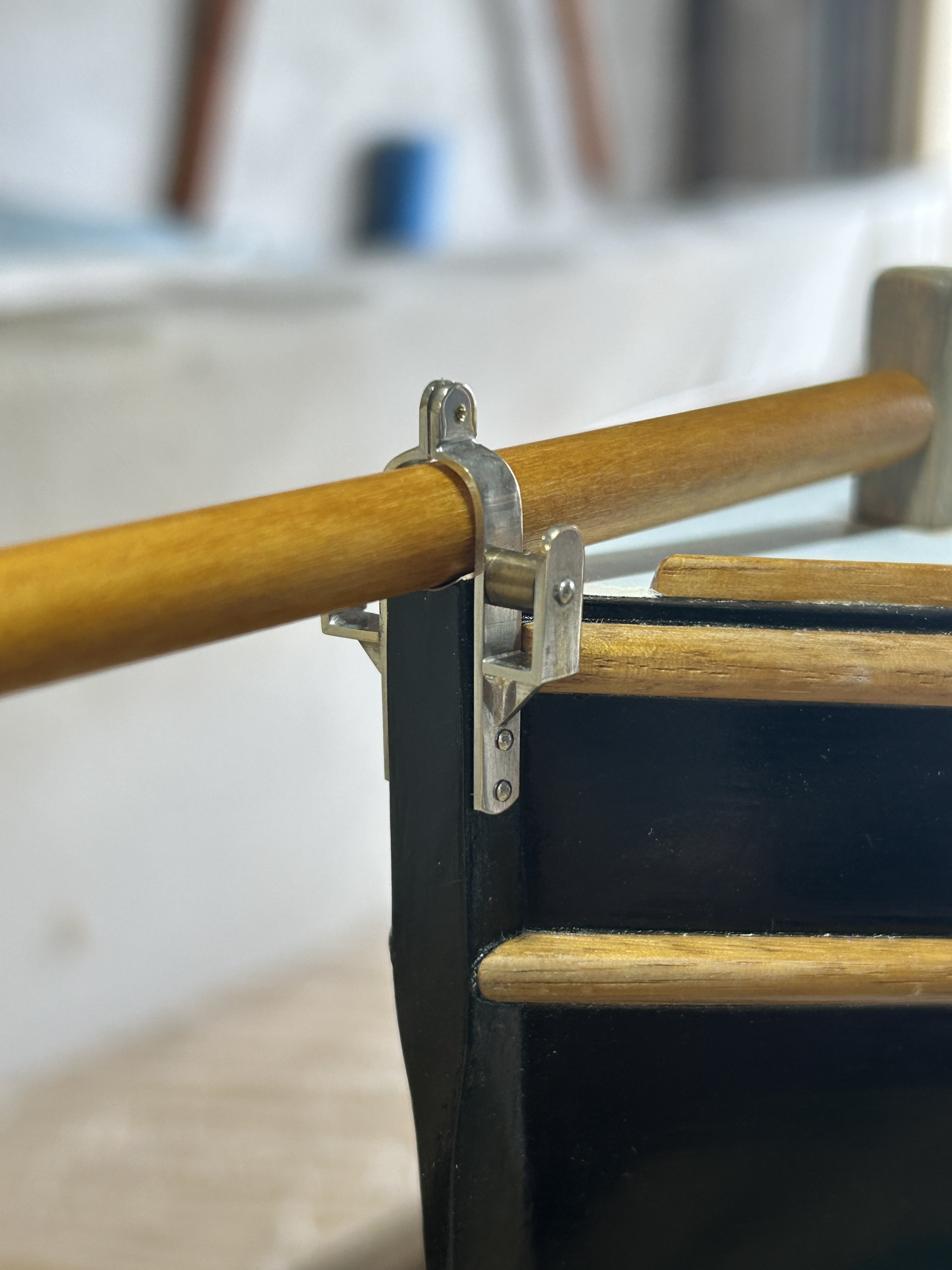
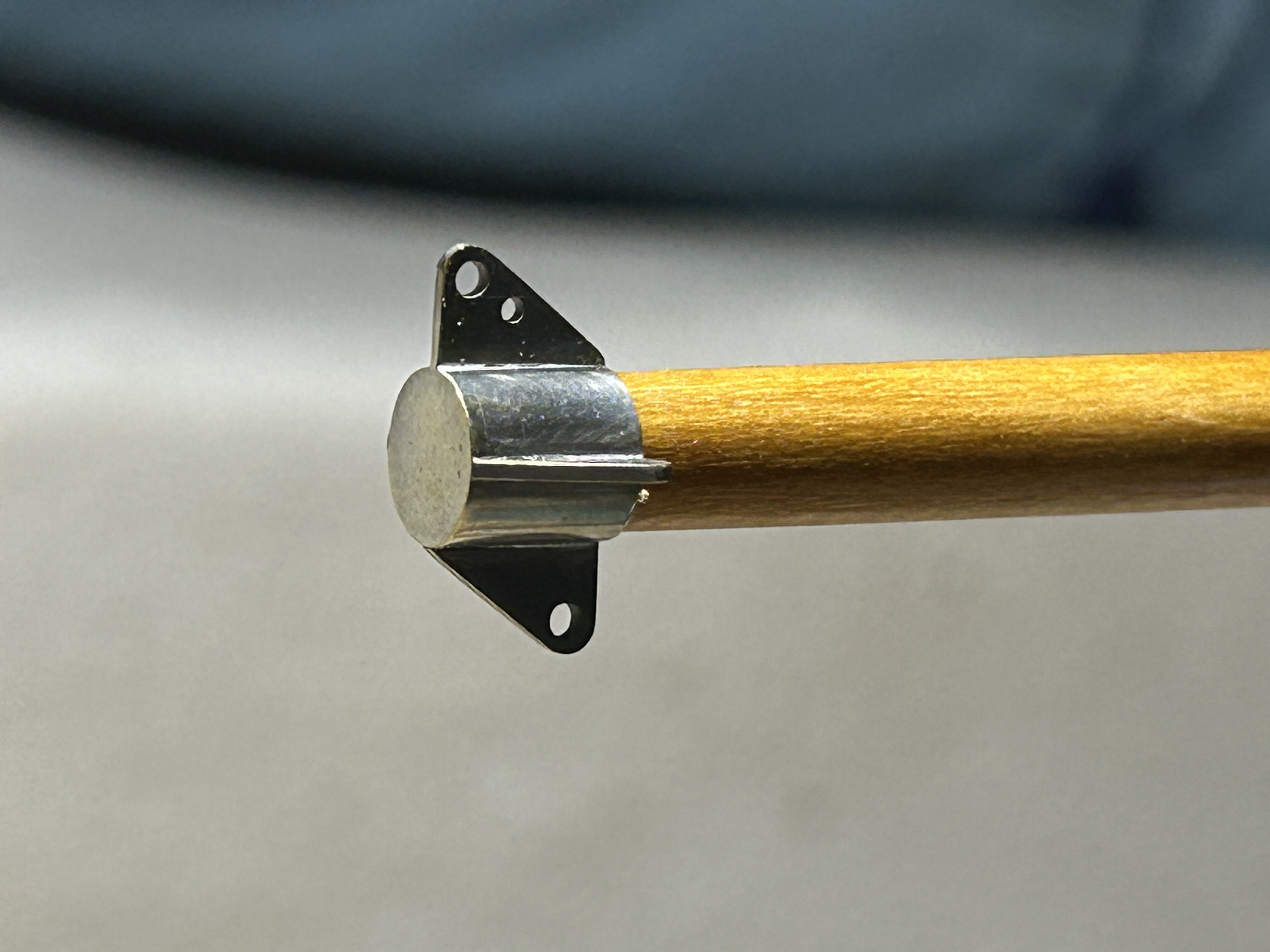
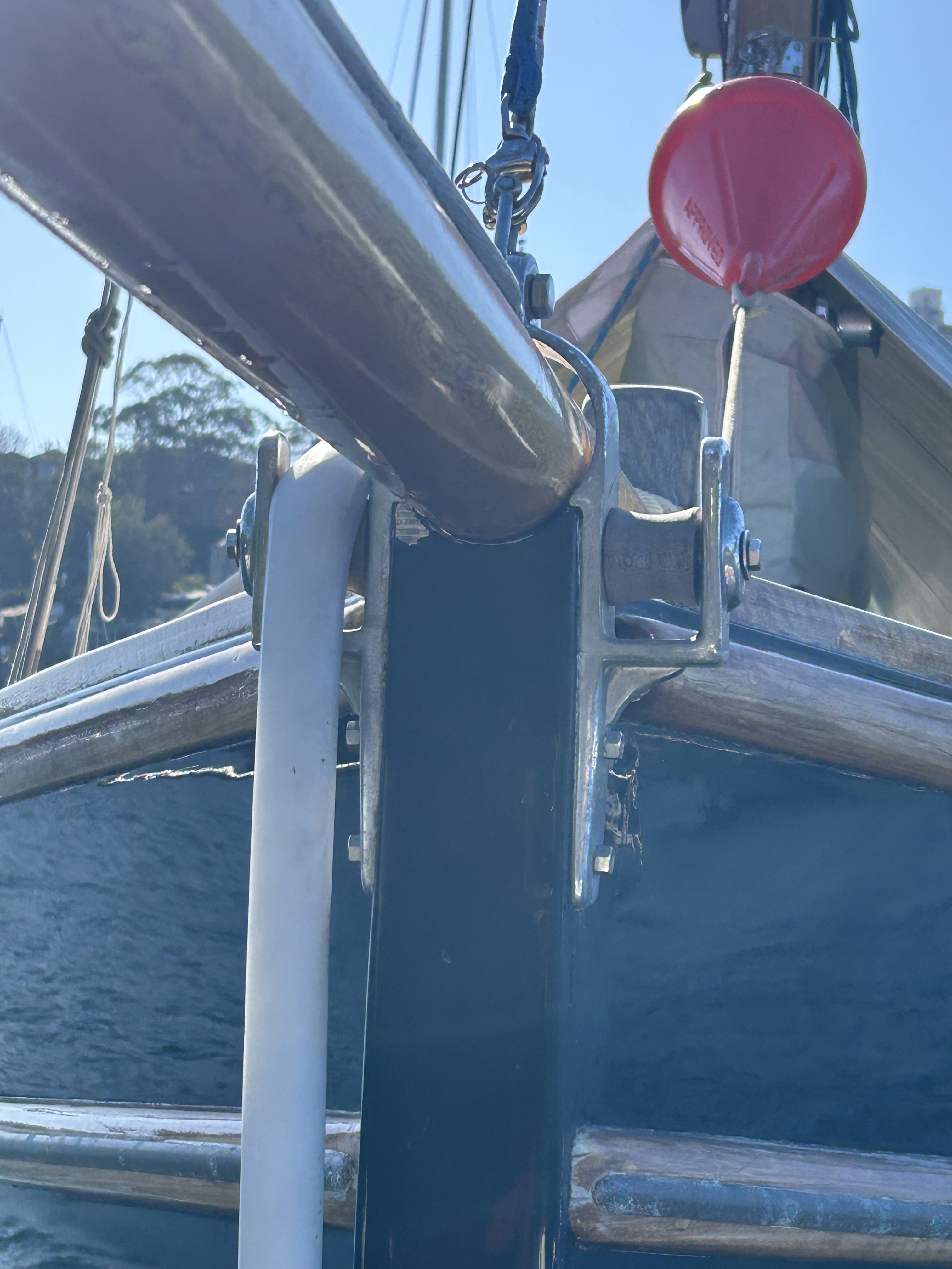
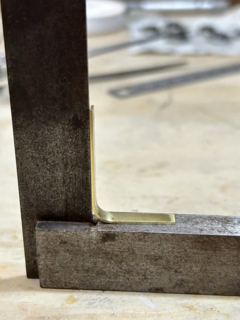
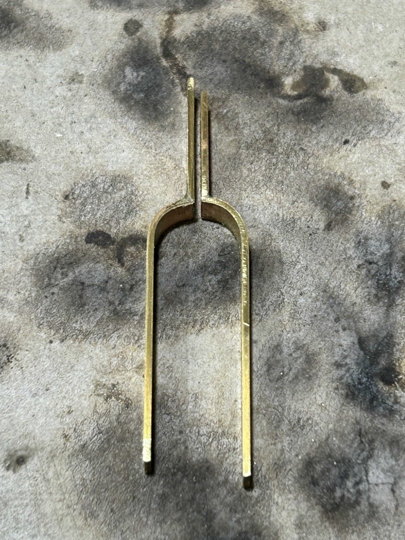
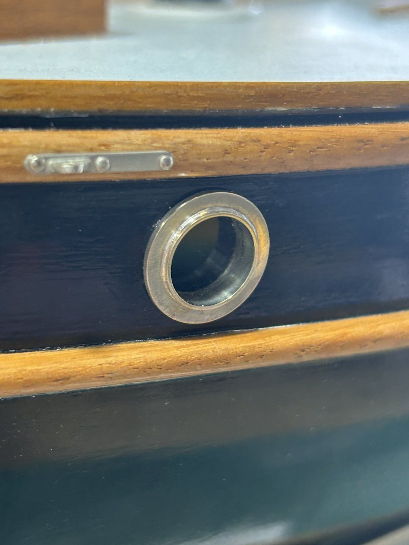
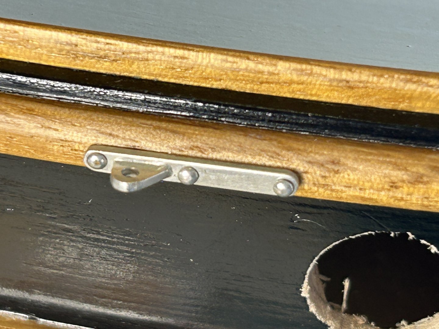
Thank you. More metalwork, this time the gammon & cranse irons, & installing the portholes. The 'glass' was the right thing to do, & the effect of the reflection heightens the depth relative to the hull line. Thanks for the frank advice, it was good. The cranse iron done & on the end of the bowsprit, it's some tube, capped & with flanges. It's unusual to have the end capped, but looks good. The gammon iron is a bit more complex. Here's the actual: I had to cut some strips off 0.8mm sheet, then do 90º bends around a suitable rod. Adjust to square: The back-cut v joints for the 90º folds: Soldered: Then the brackets that take the bow rollers, plated etc. The rollers are tufnol I think, so they are coloured brass. And installed. The bracket at the top still needs a 'bolt'. The bowsprit on the actual boat is (what we call) Oregon Pine, I think is actually called Douglass Fir, so mid orangey brown, the scale one is Limewood, with enough coats of shellac to get the colour. thanks all,


-
Hi Trevor I will follow with great interest, I like 1:12 & hope to build a scale of an open rowing skiff one day.
-
a great job & a very interesting ship, & I found your improvements also very interesting
- 97 replies
-
- 1
-

-
- Corel
- Große Jacht
- (and 2 more)
-
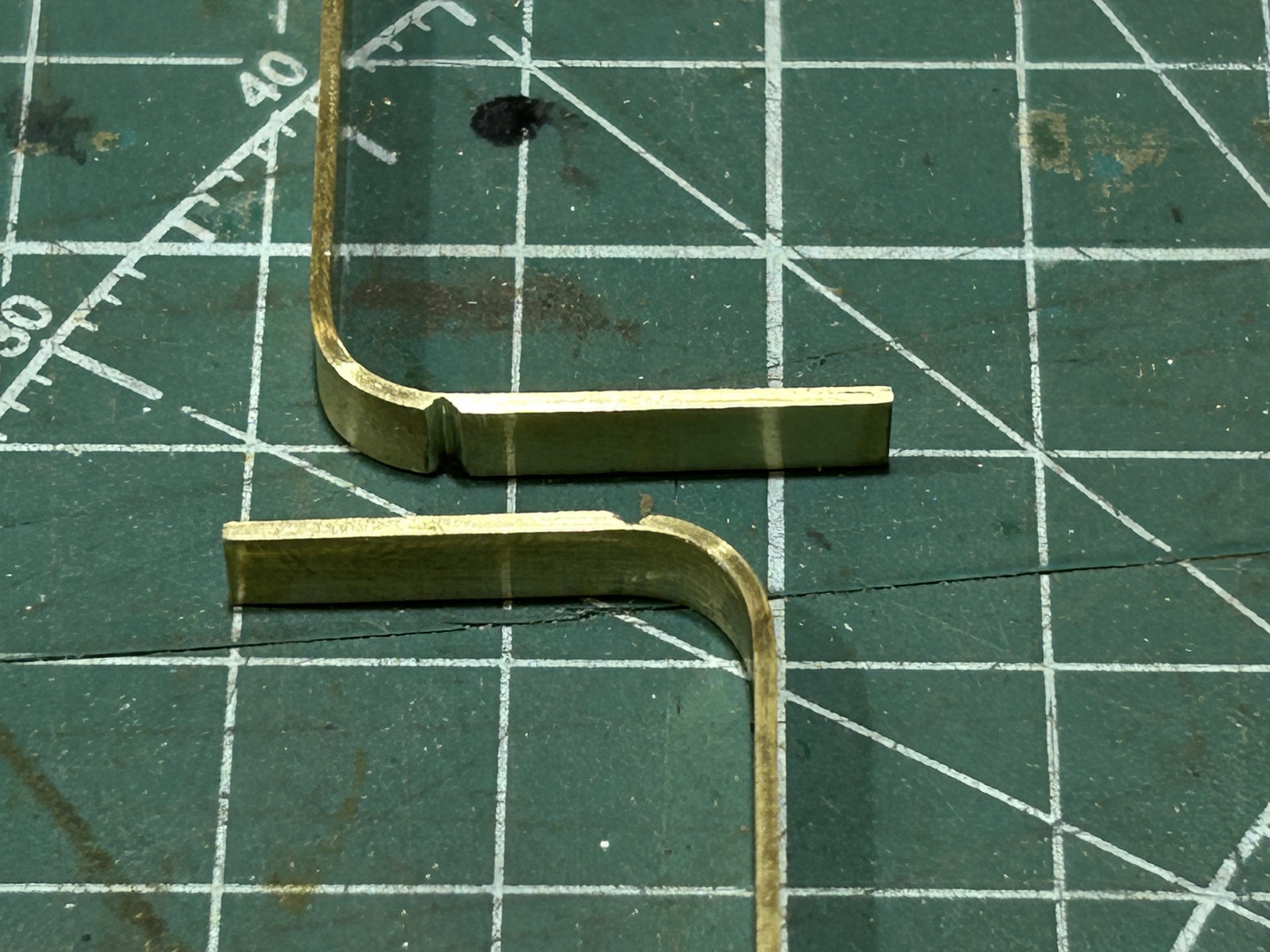
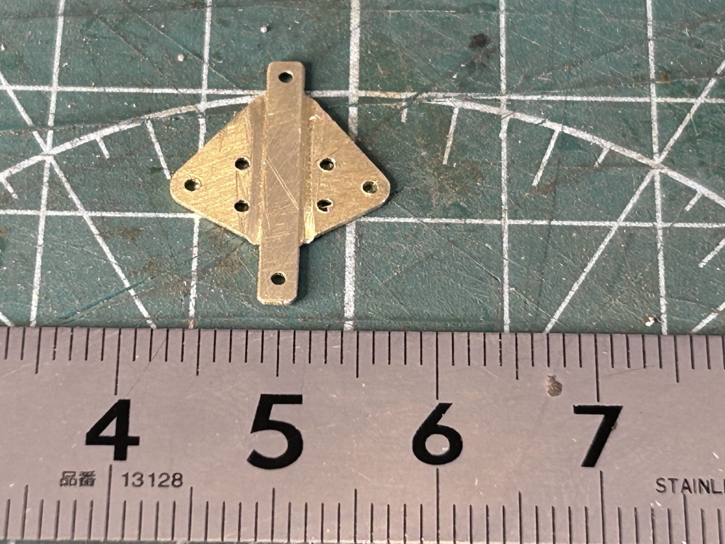
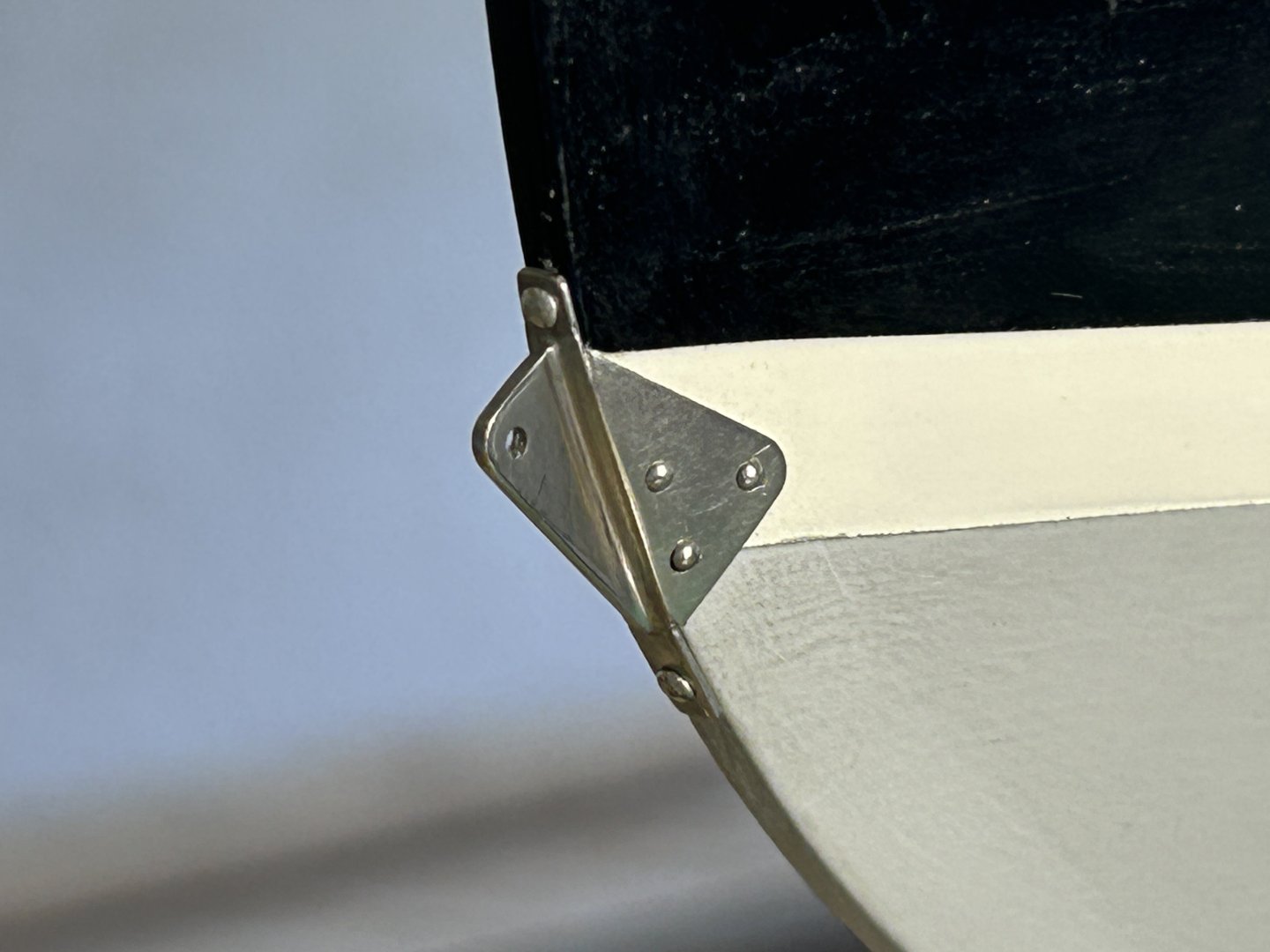
Thanks everyone. More metalwork: this time the bowsprit chain plates. The whisker stay chain plates are pretty straightforward, note the portholes openings have been cut. 0.8mm brass sheet, which is probably a little heavy. The bobstay chainplate is more complex, & it became clear that with my simple kit multiple solder joints in this case would be very difficult, so I made the main parts from one sheet (0.5mm), with back-mitres so it could be folded & then soldered to fill & stabilise the folds. Then the chainplate cleat was soldered to the edge, tinned etc (cleat 0.8mm thick). A paper template was used to confirm the fold angles, as brass is only happy to be folded once, & solder never.... The fixings are some 1mm diameter brass rivets approximately 7mm long, so a 1mm hole, add some CA glue & press the rivet into it. The back-mitring was done with a jeweller's saw & also a small file with a square cross section. The mitre is also slightly wider towards the edges, so that the main piece could be curved to suit the stem profile. The side flange fixings are some unbelievably tiny brass nails, too small & I could hardly pick them up.
-
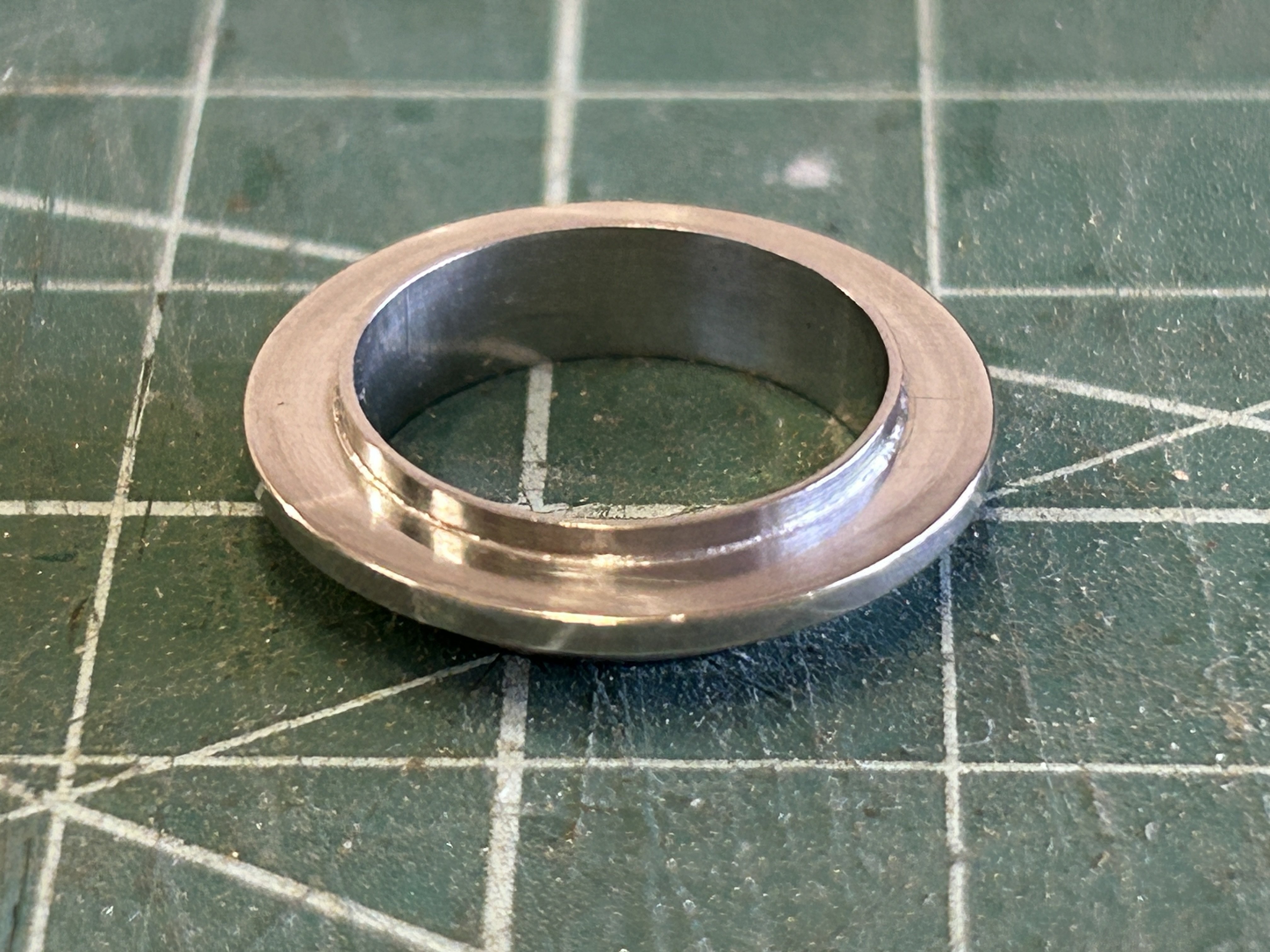
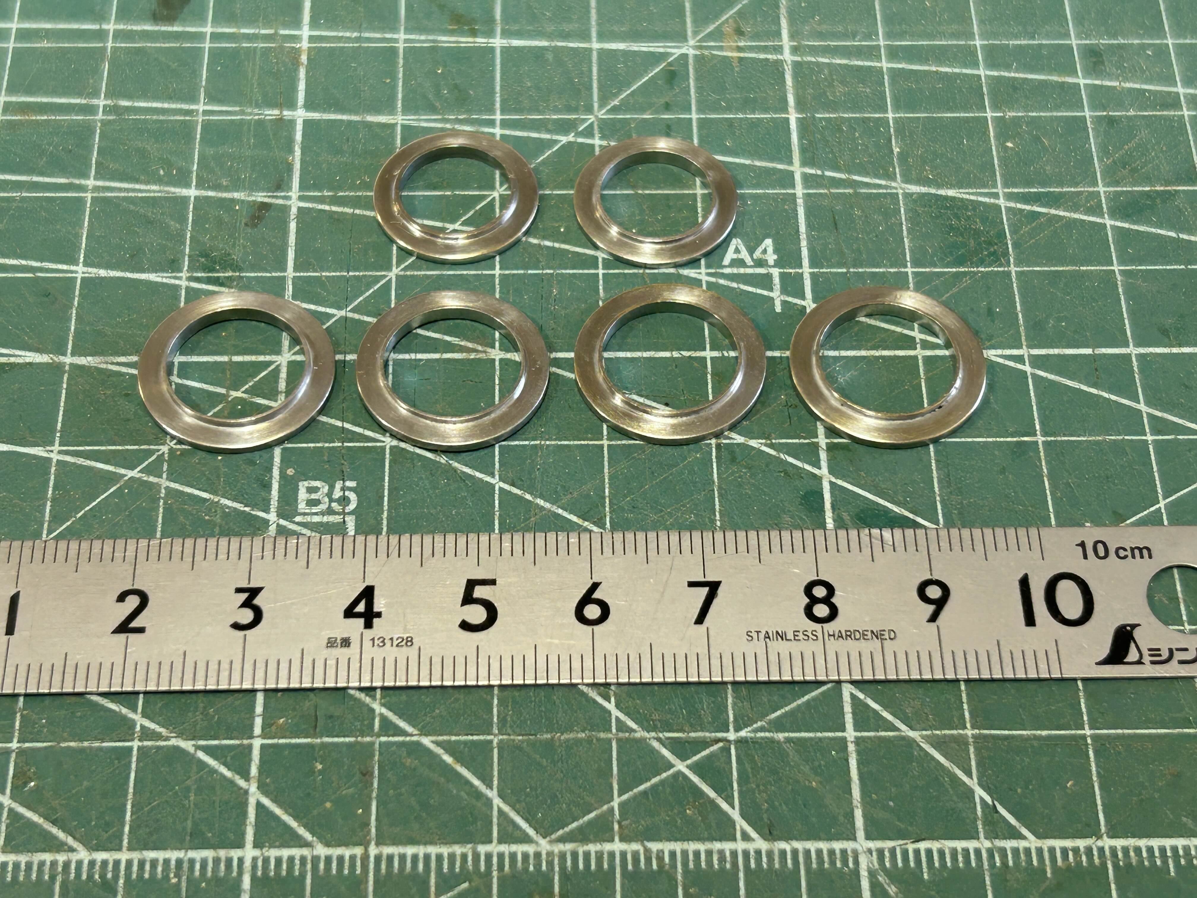
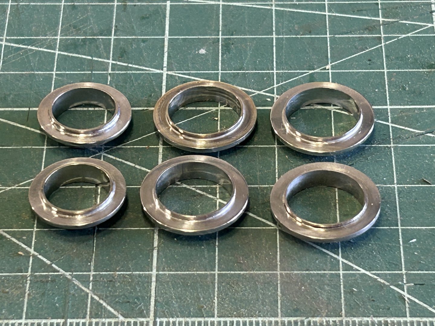
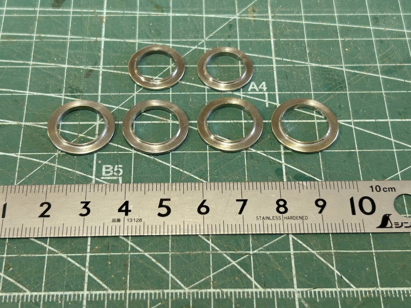
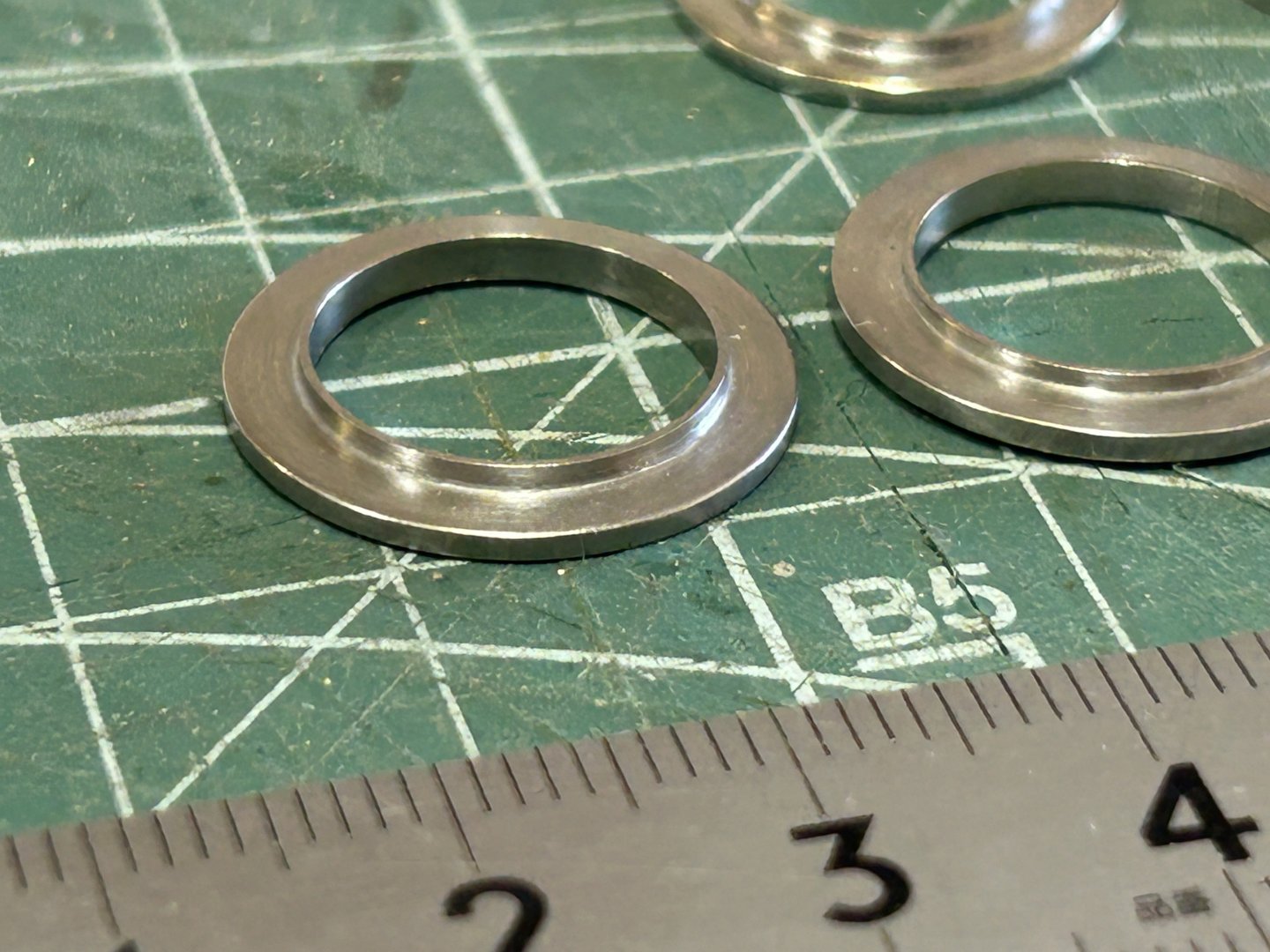
Thank you for the advice re the glazing of the portholes, & I have taken that advice. Also, I did pick up an error in the portholes as previously made, which has now been corrected. I went to the boat to confirm the setout of the portholes & saw that the glass is actually set back from plane of the hull, I assumed it was in the same plane - soooo, back to the drawing board. I was able to salvage the rings, they were the part that took some time. So, now remade & awaiting some 1mm acrylic sheet. I will work out some way to increase the gluing surface area for the acrylic, probably some tabs that glue to the outside back part of the tube. And all done. Some of them in the photo below appear to have flaws in the soldering joint - that's just a trick of the reflections, the joints all came out well.

-
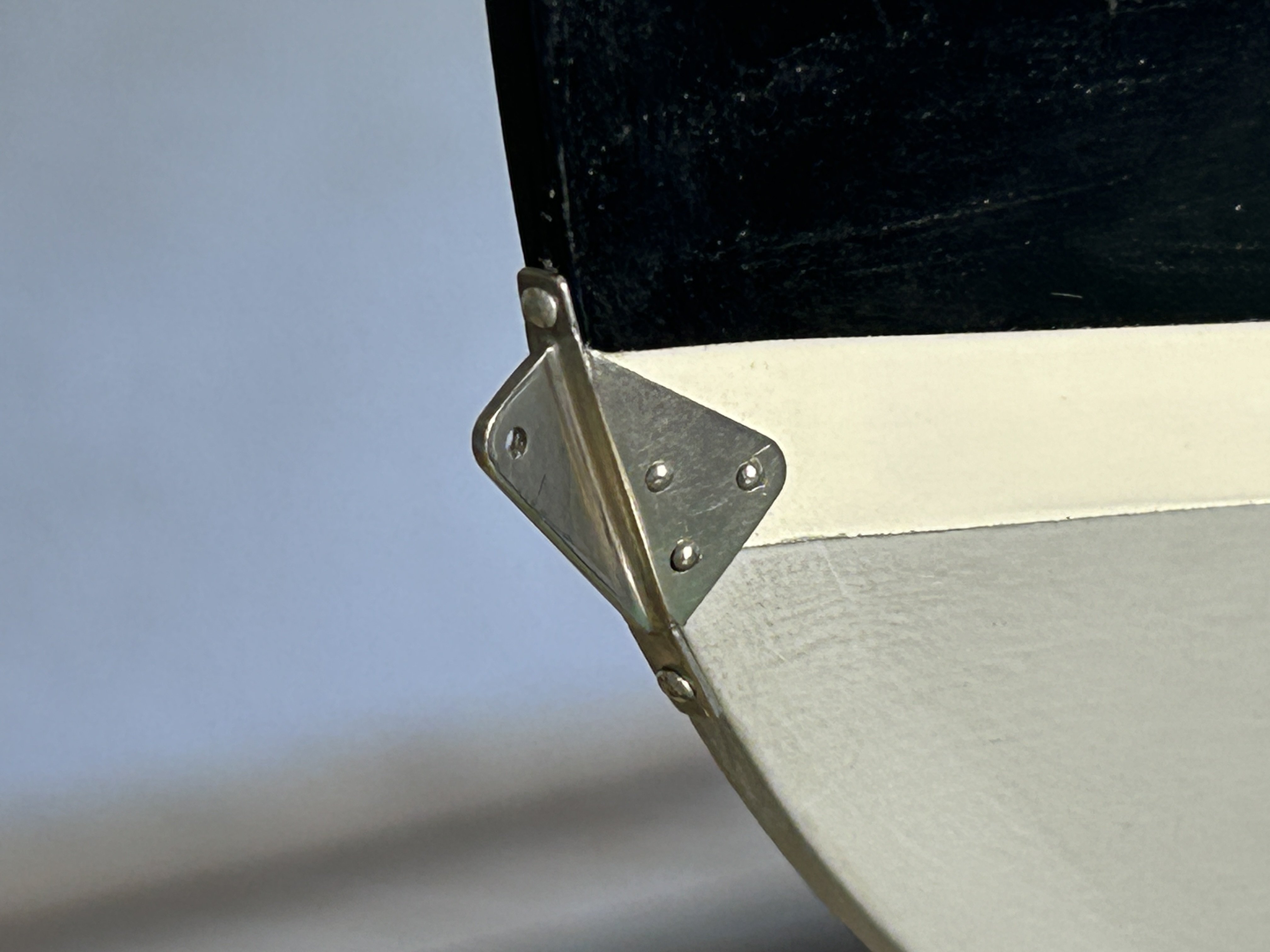
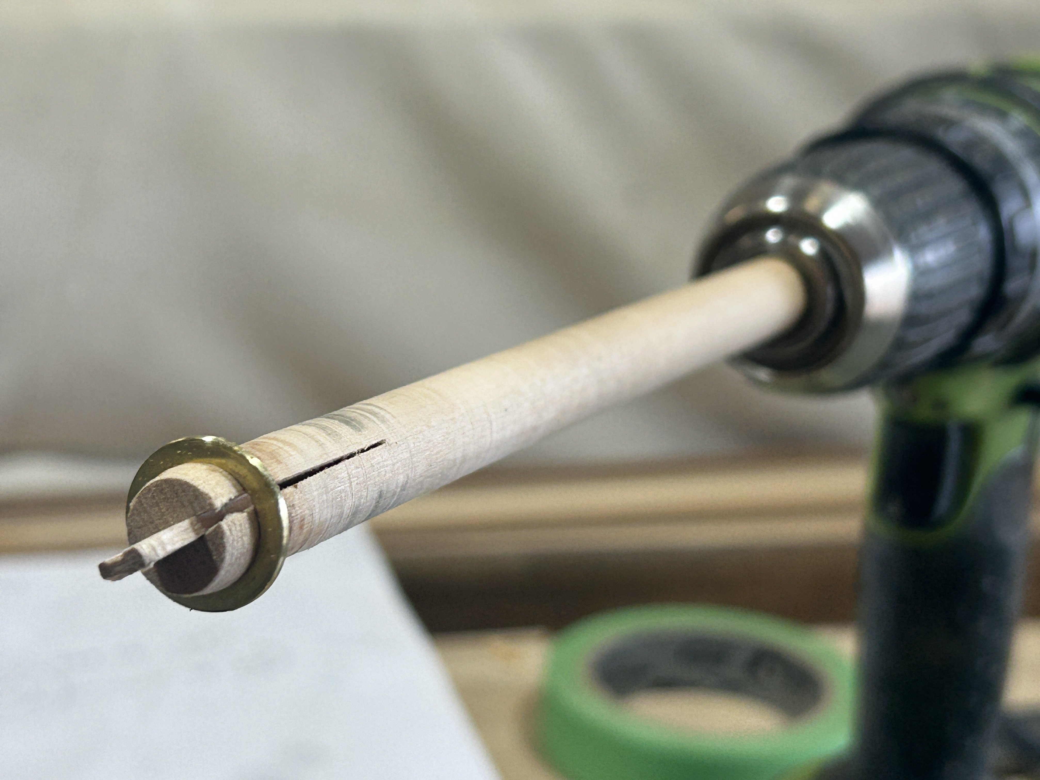
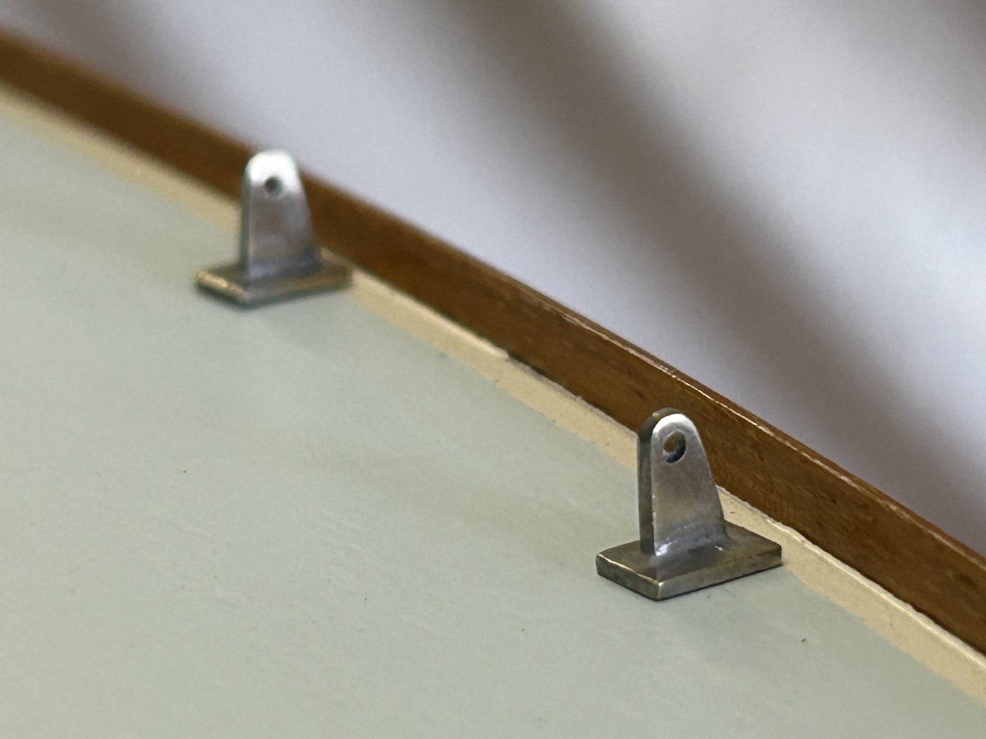
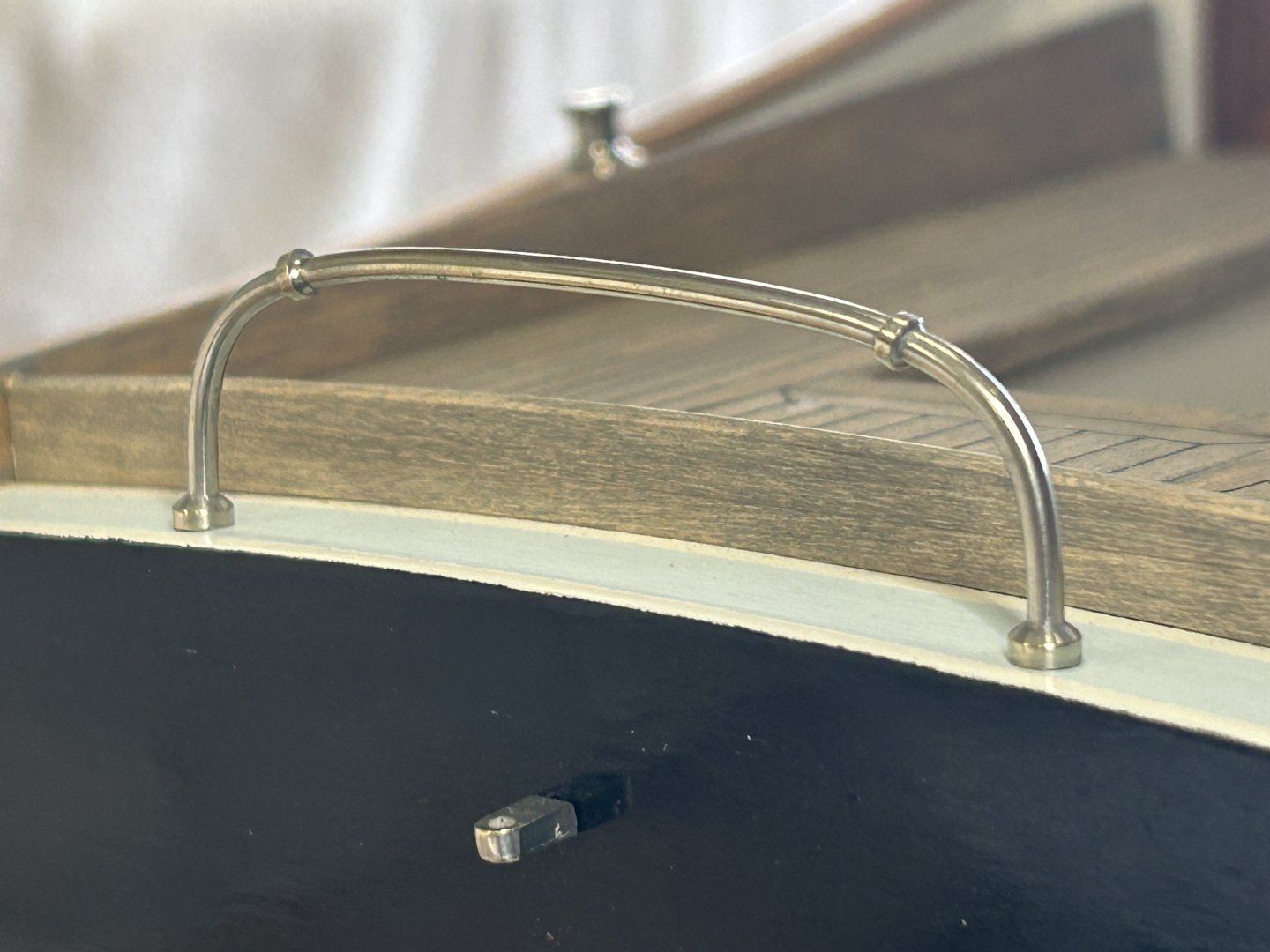
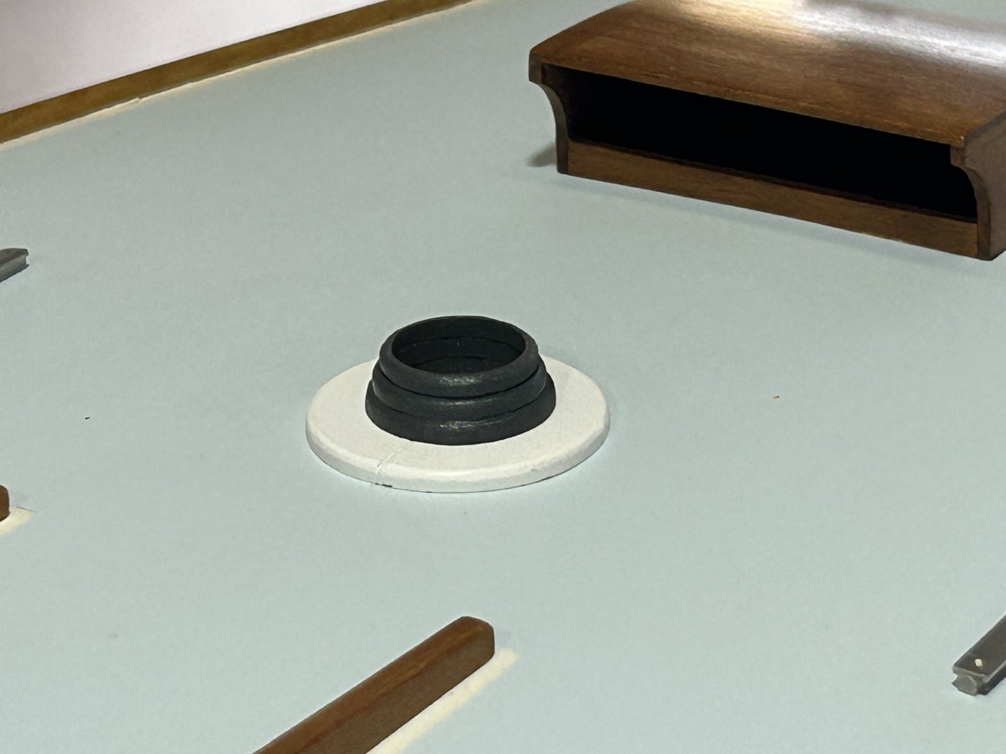
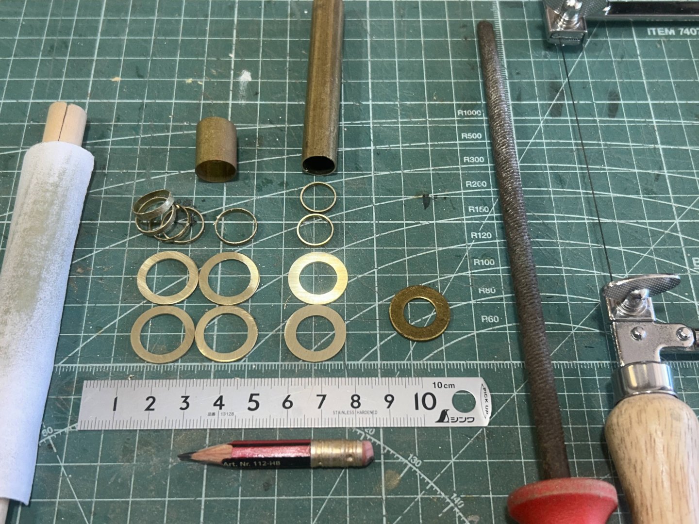
On with the various details: Chain plates plated & installed with glue, nb: with a 1mm diameter brass rod below, into the deck structure. The traveller is from 2mm brass rod, & the details from brass rod centre drilled to slide on. I made a cardboard template to bend the shape over, although it didn't work fully as the shallow curve had to be done by hand as the metal didn't take the shape on the template. The legs extended down into timber take give a good glue fix. Tinned & polished. The purchased scale winches were plated, & with the spacers for the smaller ones - kindly made by Bedford - fitted, they look good. Also, small bevels to the lower outer edges, to look right they must have a small gap to the timber they sit on. The mast seal was made from 4x 2mm acrylic layers, laser cut into sized doughnuts & sanded to give the rounded edges, painted etc. The actual fitting is a roofing rubber seal with a rubber piece that can be trimmed to suit the size of the pipe (or mast). And the portholes...I had some brass washers & started by enlarging the centre holes to suit. 2 small & 4 large. The washer is on the right, on the left are the washers with the ID adjusted, by hand with the rat tail file & finished with sandpaper wrapped on some dowel. I then had to reduce the OD, & for this I made another version of the home-made lathe. This time using a piece of timber dowel with a centre cut & a timber wedge to lock the washers in place, Crude, but it worked well. I held sandpaper against the spinning edges until the diameter was right. The washers got extremely hot, so actually it was some rags below the sandpaper, & you can see the dowel is slightly scorched. Then soldered the thin wall brass tube pieces to transform them to the portholes. The lip created by the tubing is a small but visually significant detail. In this case I won't show the fixings (6x c/sunk bolt heads on the flanges), as I believe they would be visually much more noticeable than on the actual boat, so in this case they will be left off. There are some flaws, & of course I didn't photograph those ones....but not significant enough (I think) to be an issue. The hull the portholes sit on is jet black, & won't put 'glass' into the porthole apertures. But after considering it, I will paint the part of the hull visible through the portholes - but a slightly lighter shade than full black. In reality, glass will reflect surrounding light more than the hull paint & so will appear paler. I'll do a v dark brown/grey, just add a small amount of tints to some black base. thanks,


-
wishes to you as well, Keith - & thanks for providing so much uplifting entertainment throughout the year
-
Christmas wishes to you as well, Eberhard. The model is really starting to take form now, & a pretty ship she is.
-
Hi Patrick, A very interesting vessel & a lovely model. Do we know about their sailing characteristics? Looking at her sail plan, the sail area is fairly forward, & possibly her centre of effort is forward of her centre of lateral resistance. But there's a great deal I don't know about how they could be sailed & it would be interesting to know more.
-
Very nice work, she's looking excellent.
-
NB I have been using 10 minutes in the tinning solution for all of these parts.
-
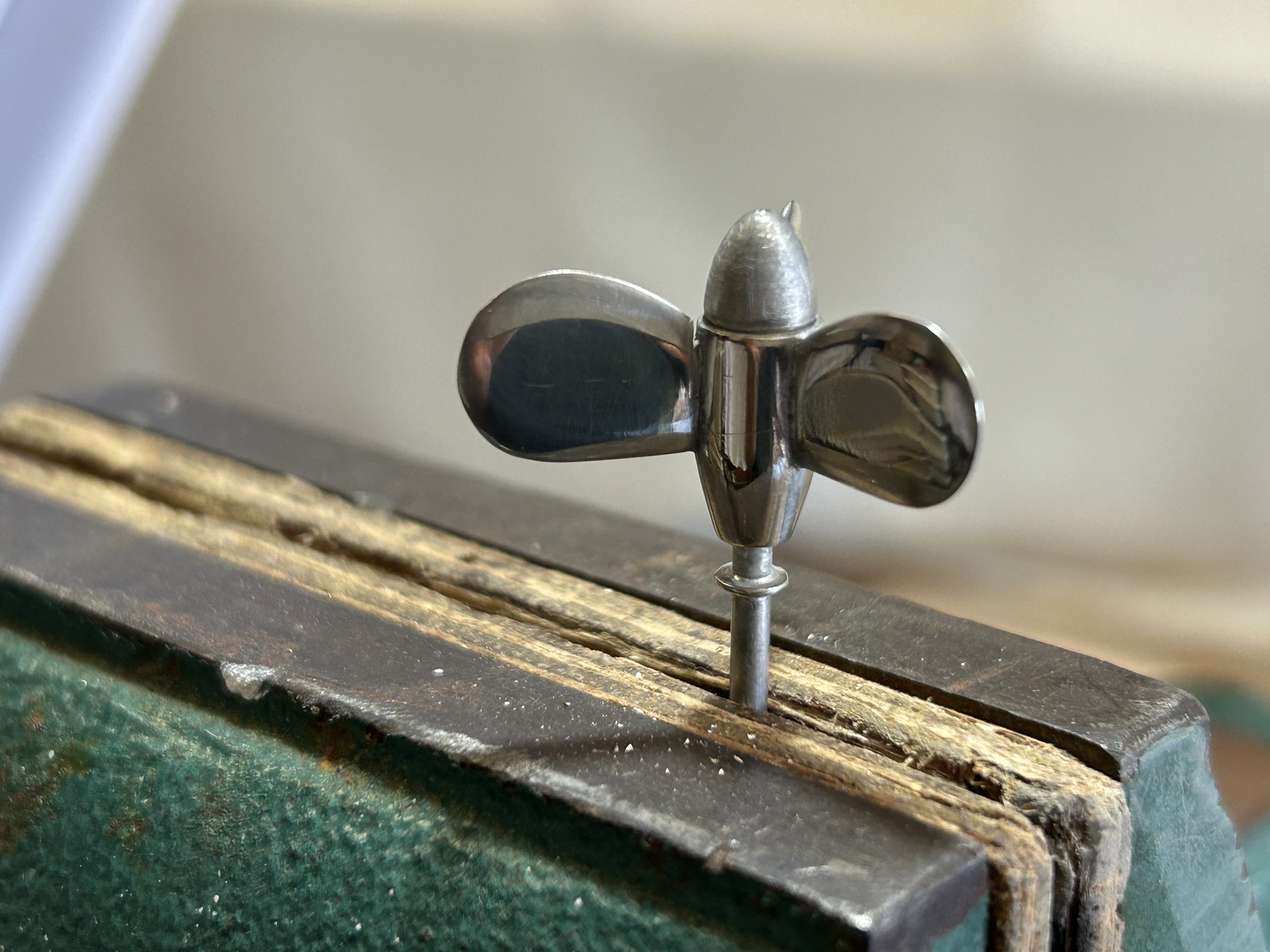
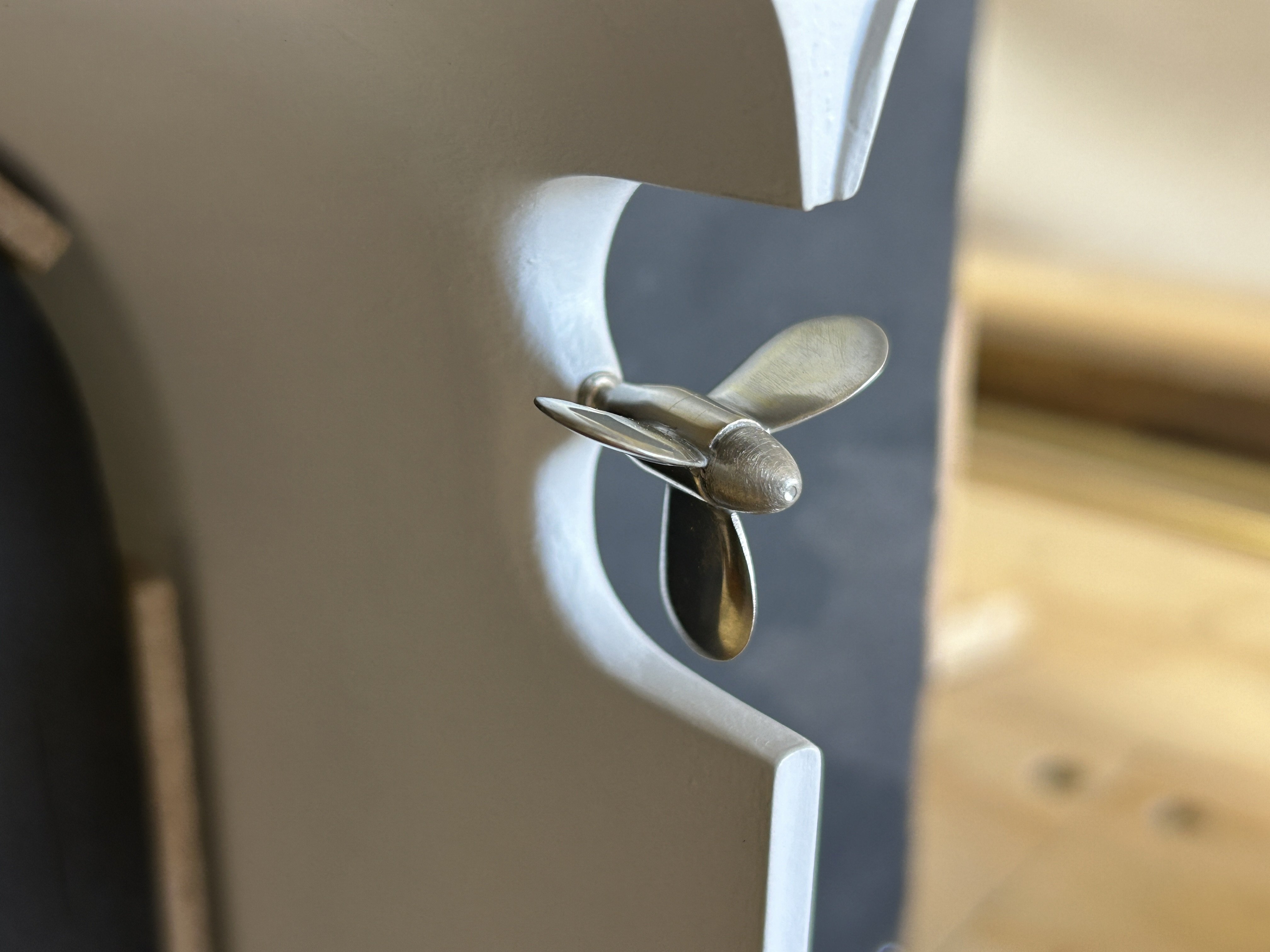
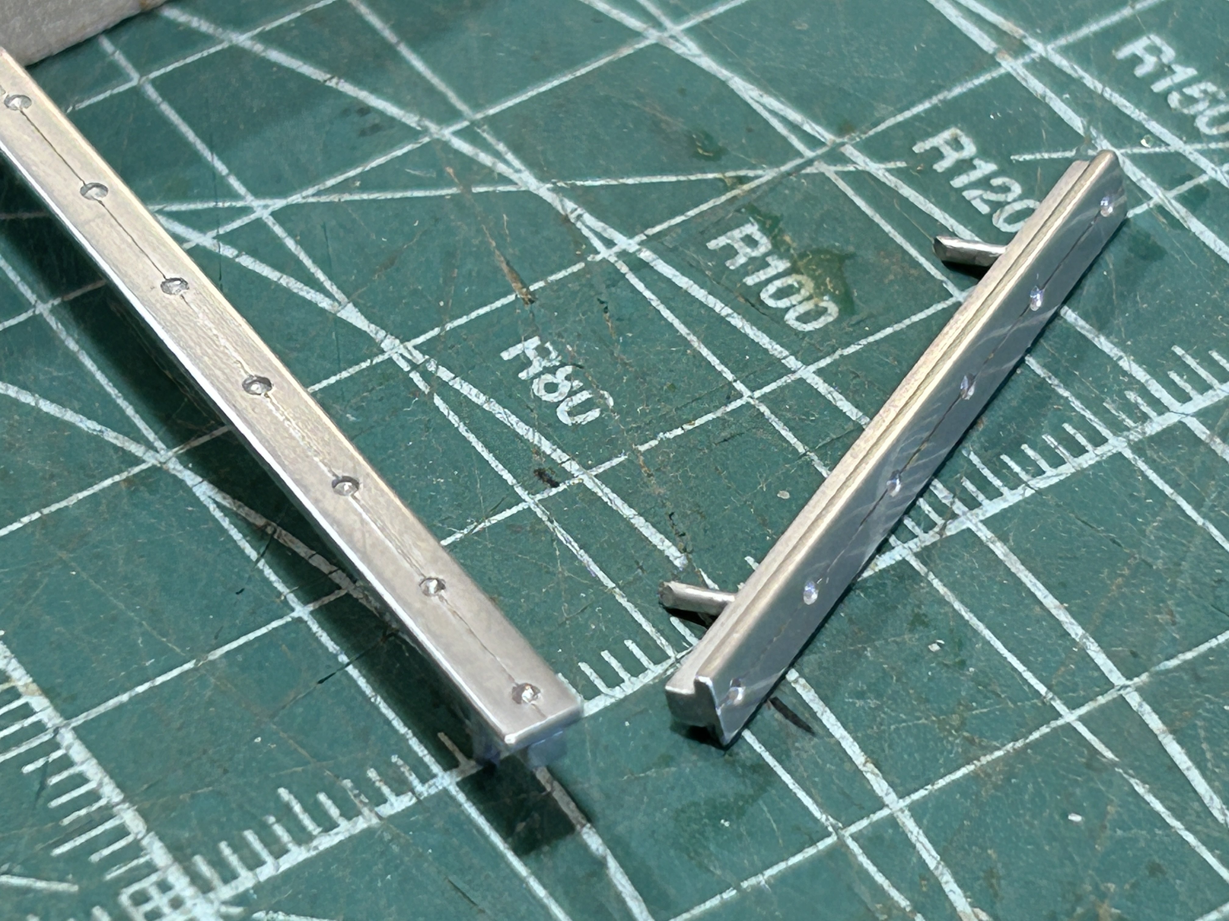
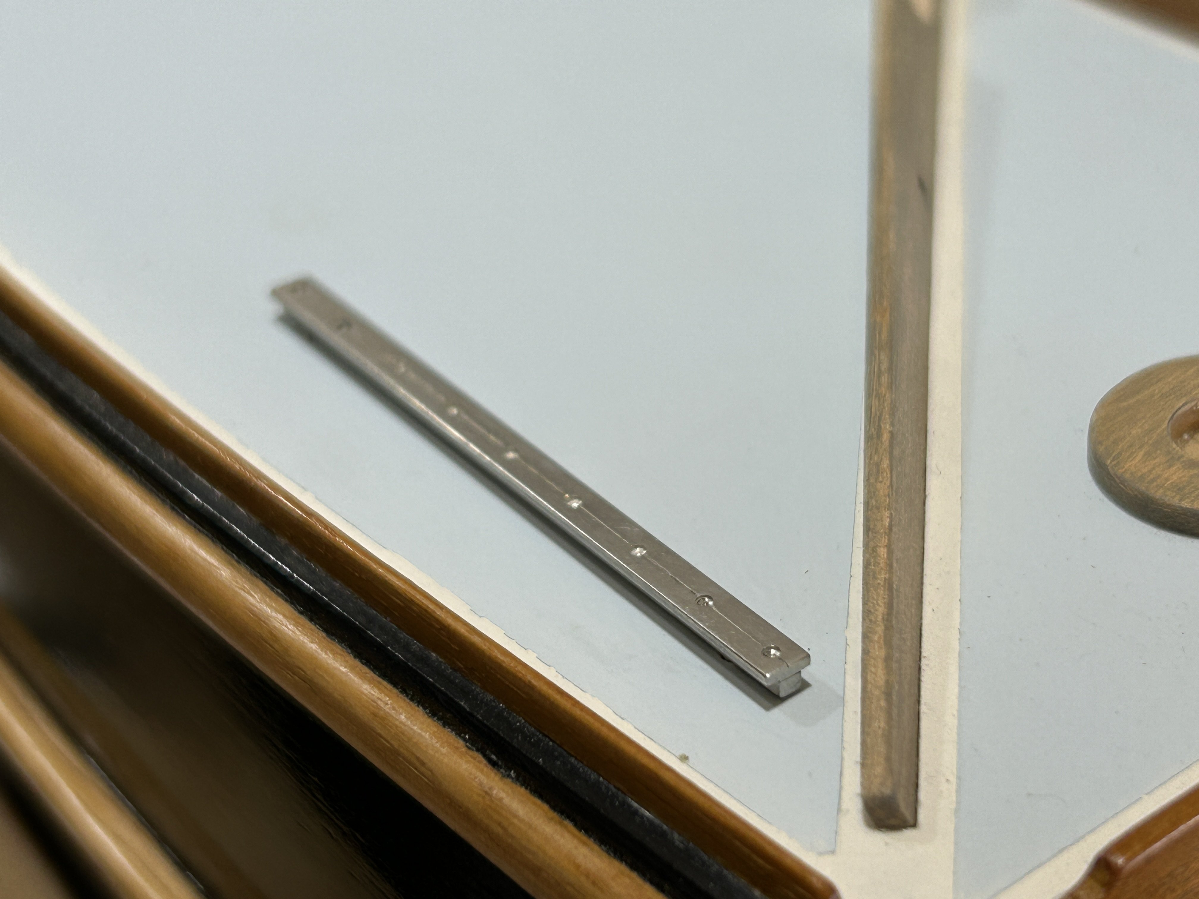
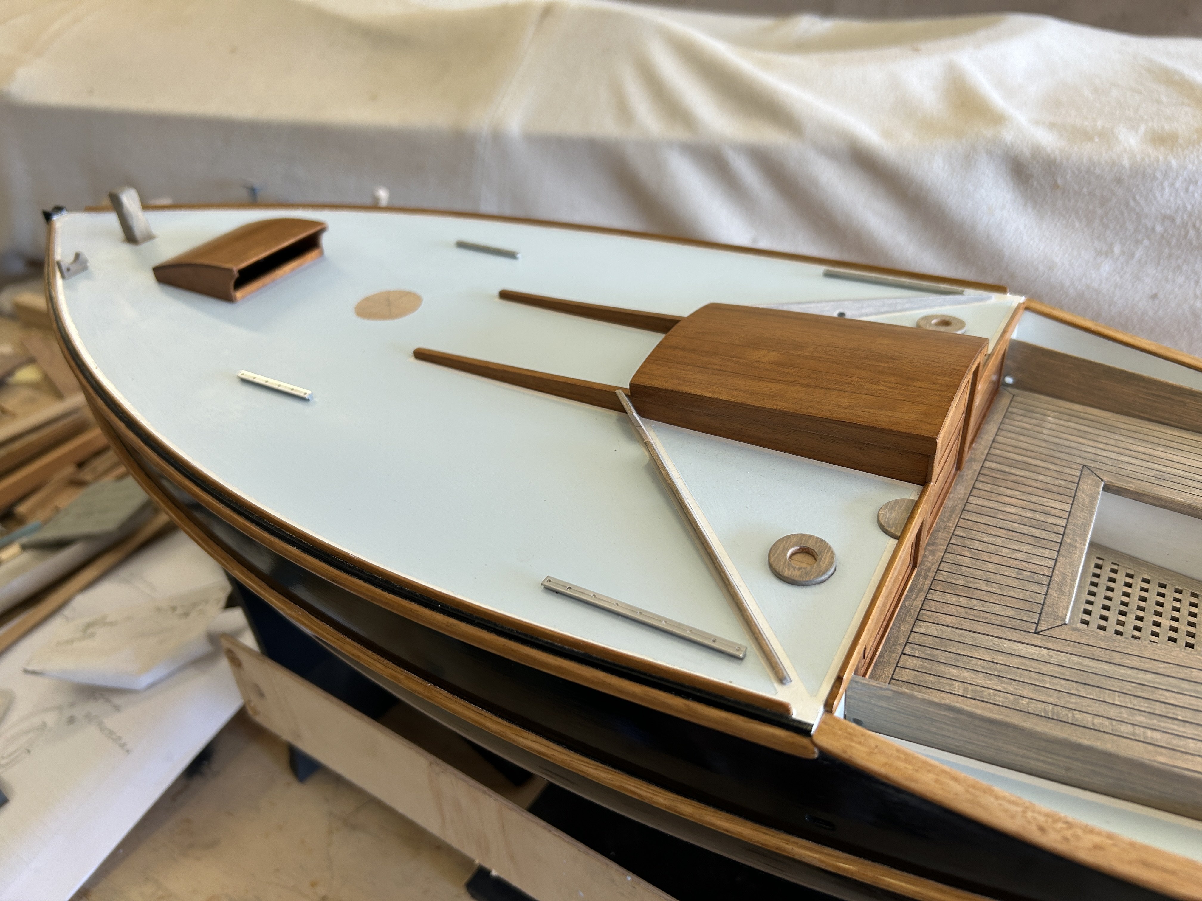
thanks all, Some more tinning, & I am very happy with the look of it. And also the adaptability, you can polish it to a mirror finish, or to a finish below that - & the impression is different with both. Also, metals are different - colour-wise silver is very warm, nickel is warm & stainless steel is cooler, more grey. The tin plating when polished has a colour similar to stainless steel. The propeller plated, & with a washer as the visible face of the bearing. Note the difference between the polished blades & satin anode, (the rounded cone). To achieve this, I gave the anode a sanding with 120 grit before the tinning. And installed: And the headsail tracks, now with brass pins on the back for fixing to the plywood deck: And installed:


-
Hi John, There must be a specific order of rigging the Duchess, I suppose follows what would be required for the ship herself. Your knowledge of these incredibly complex vessels is wonderful to follow, it would be good to hear more about how you learned it.
-
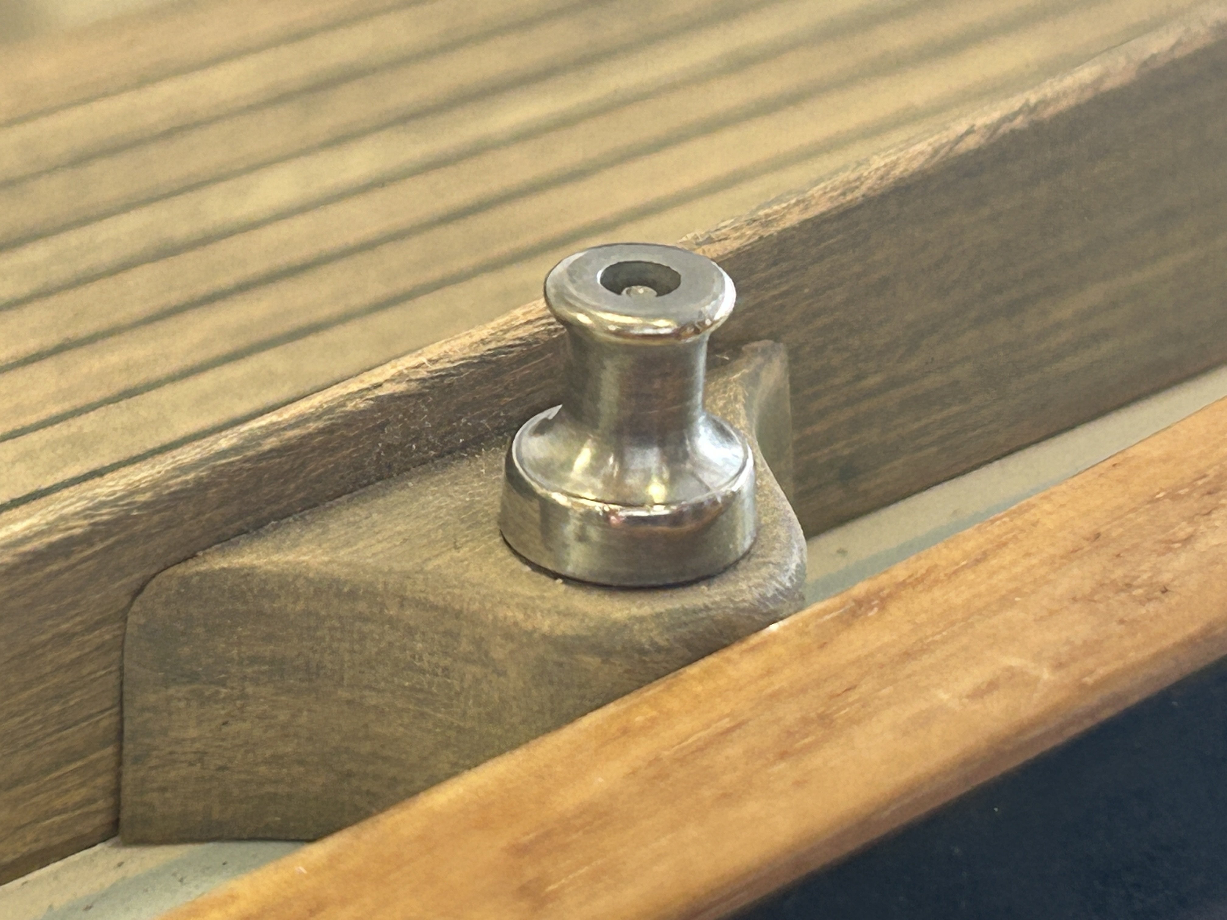
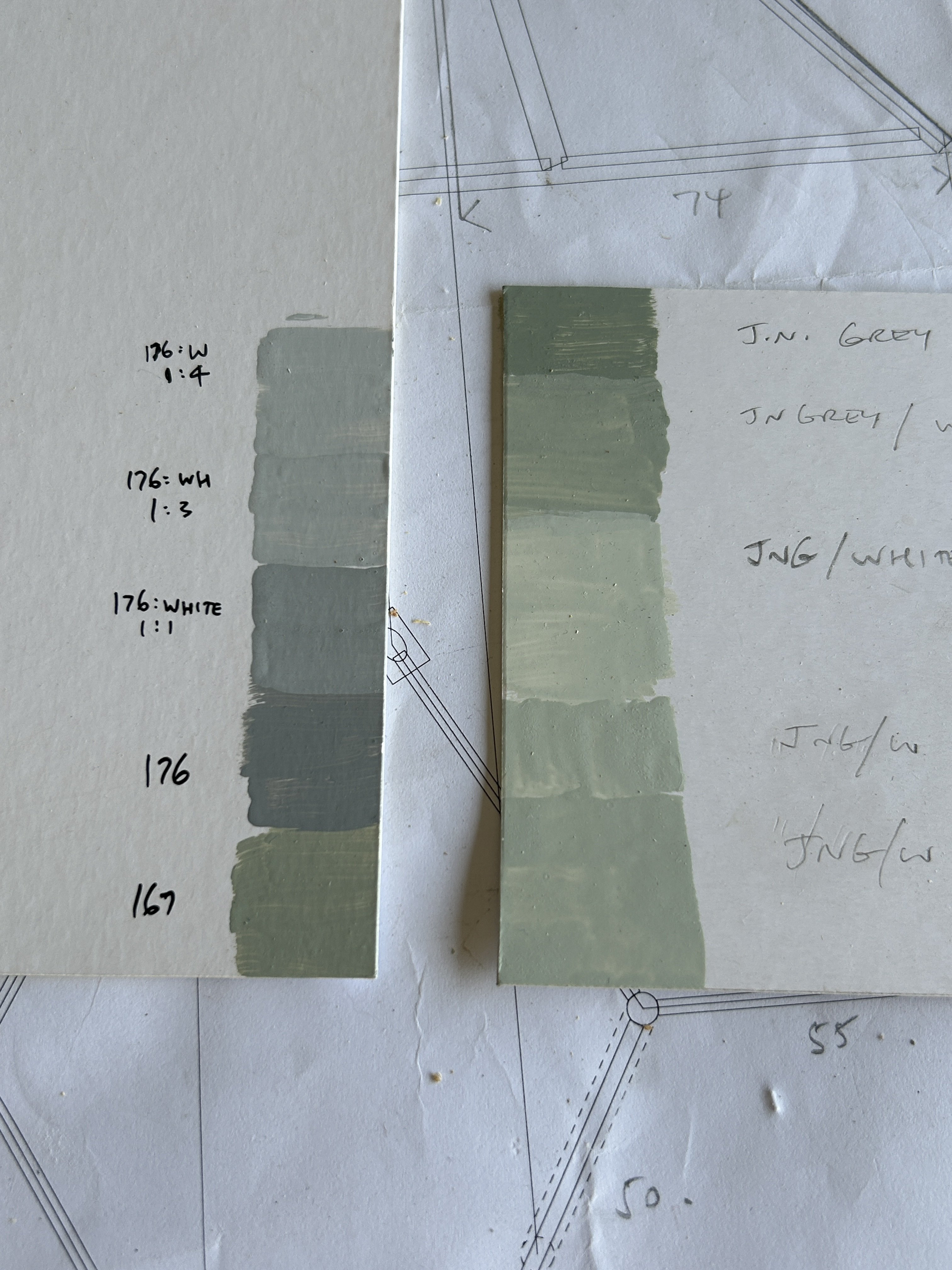
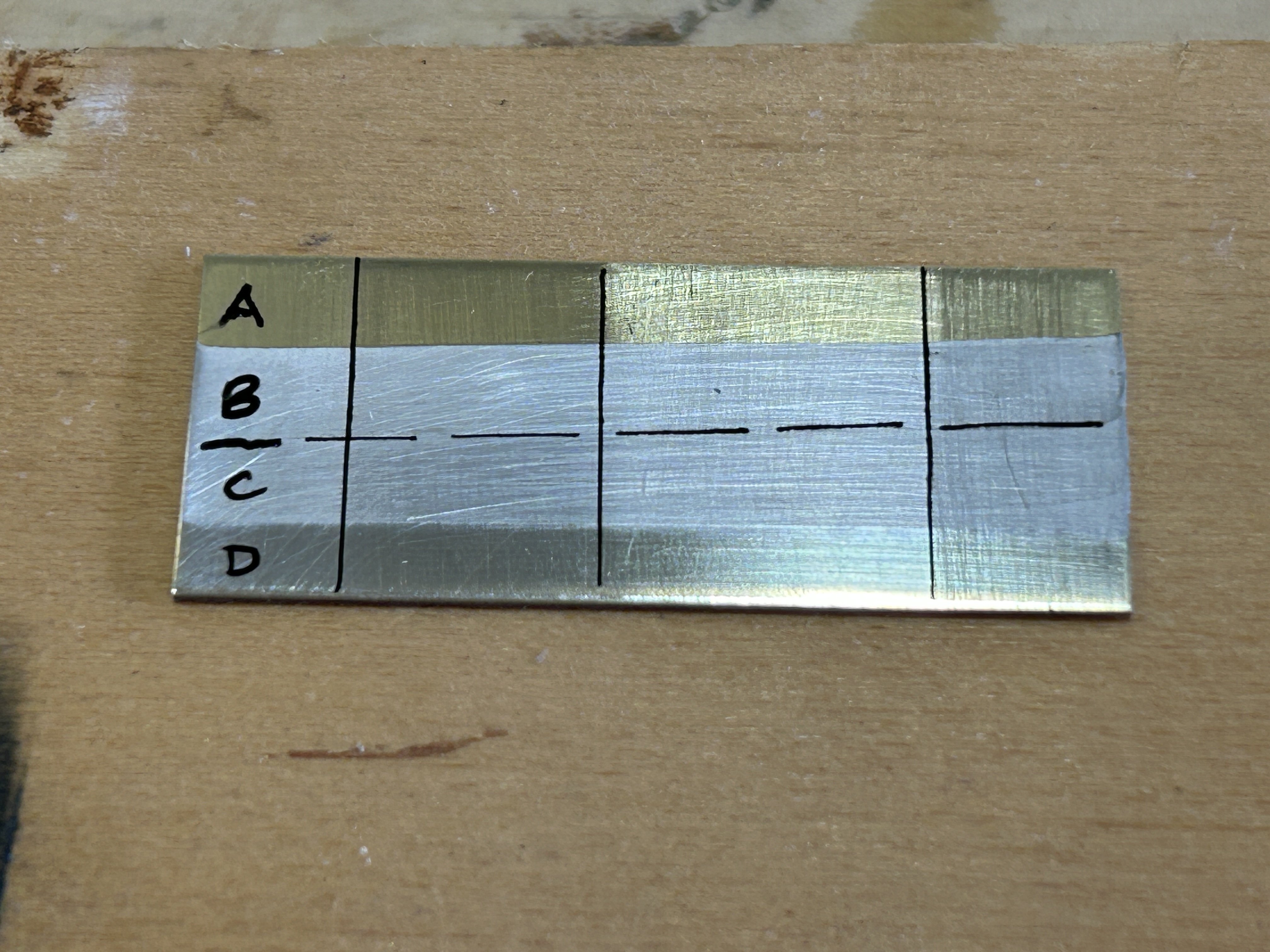
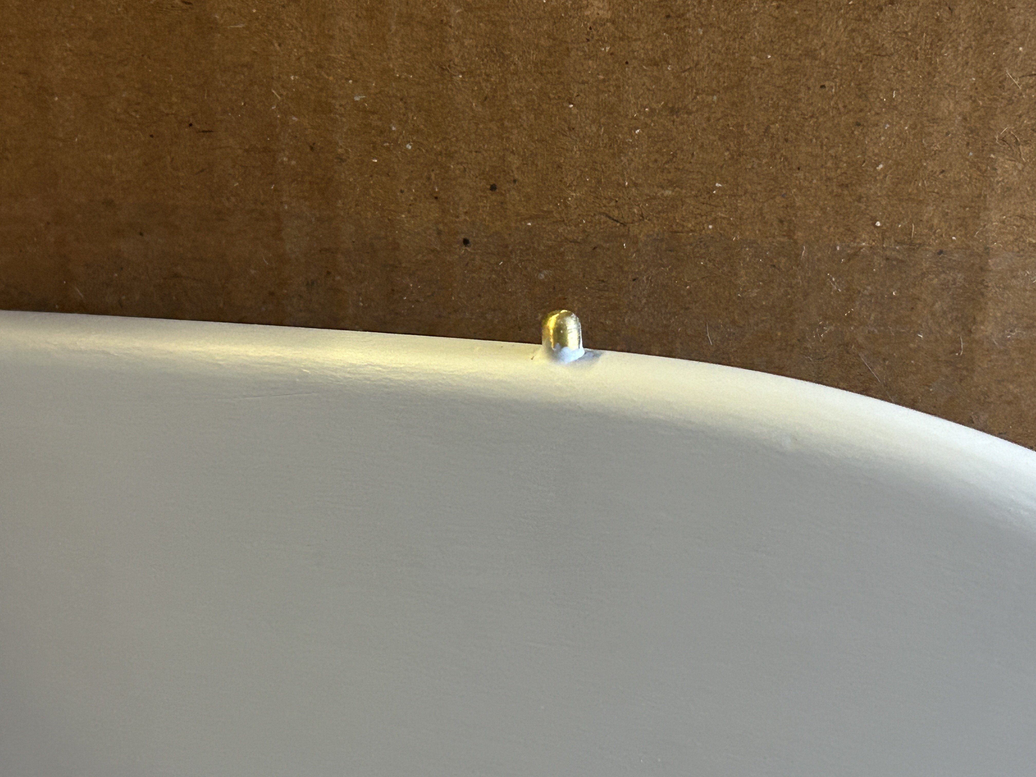
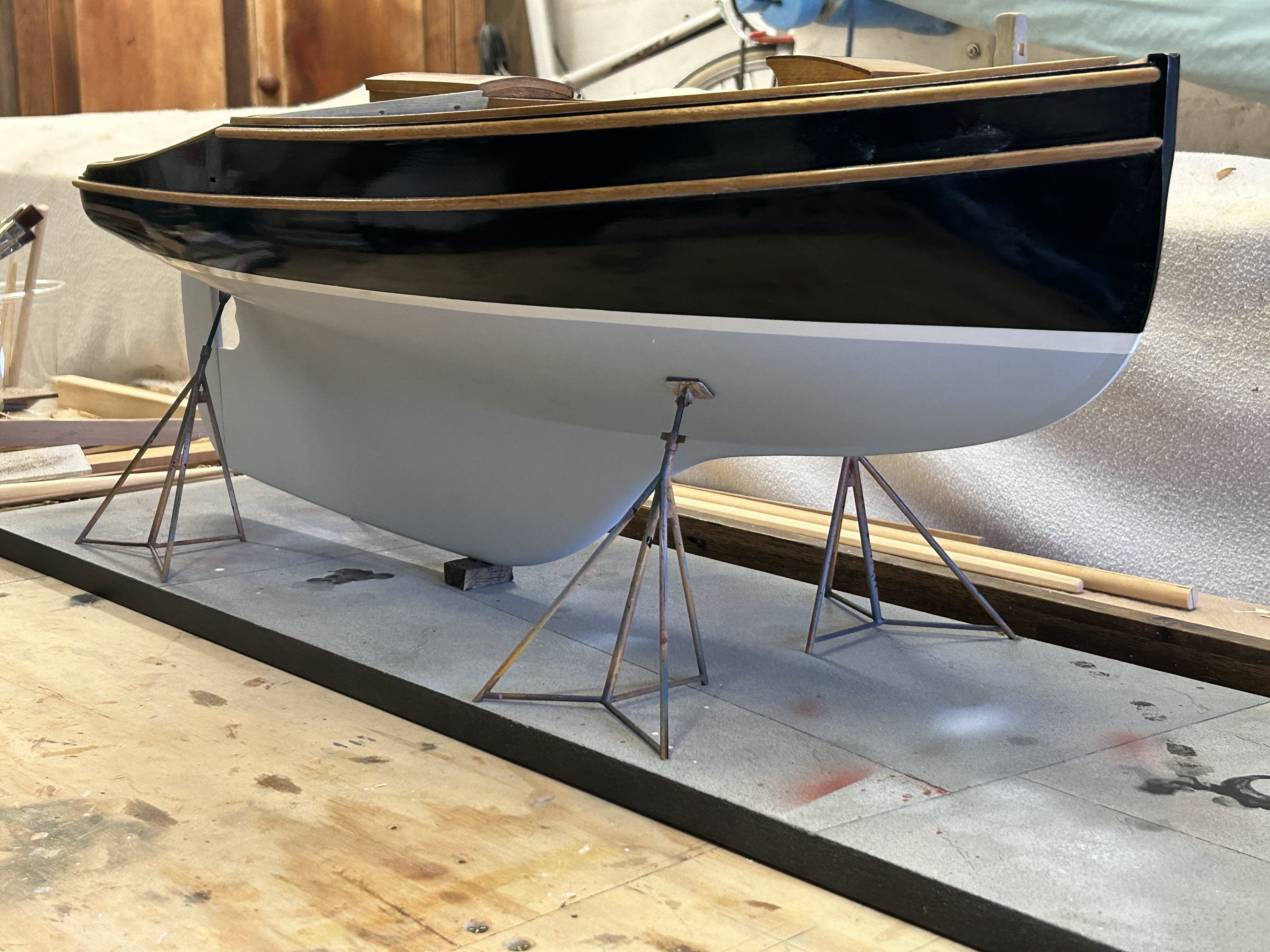
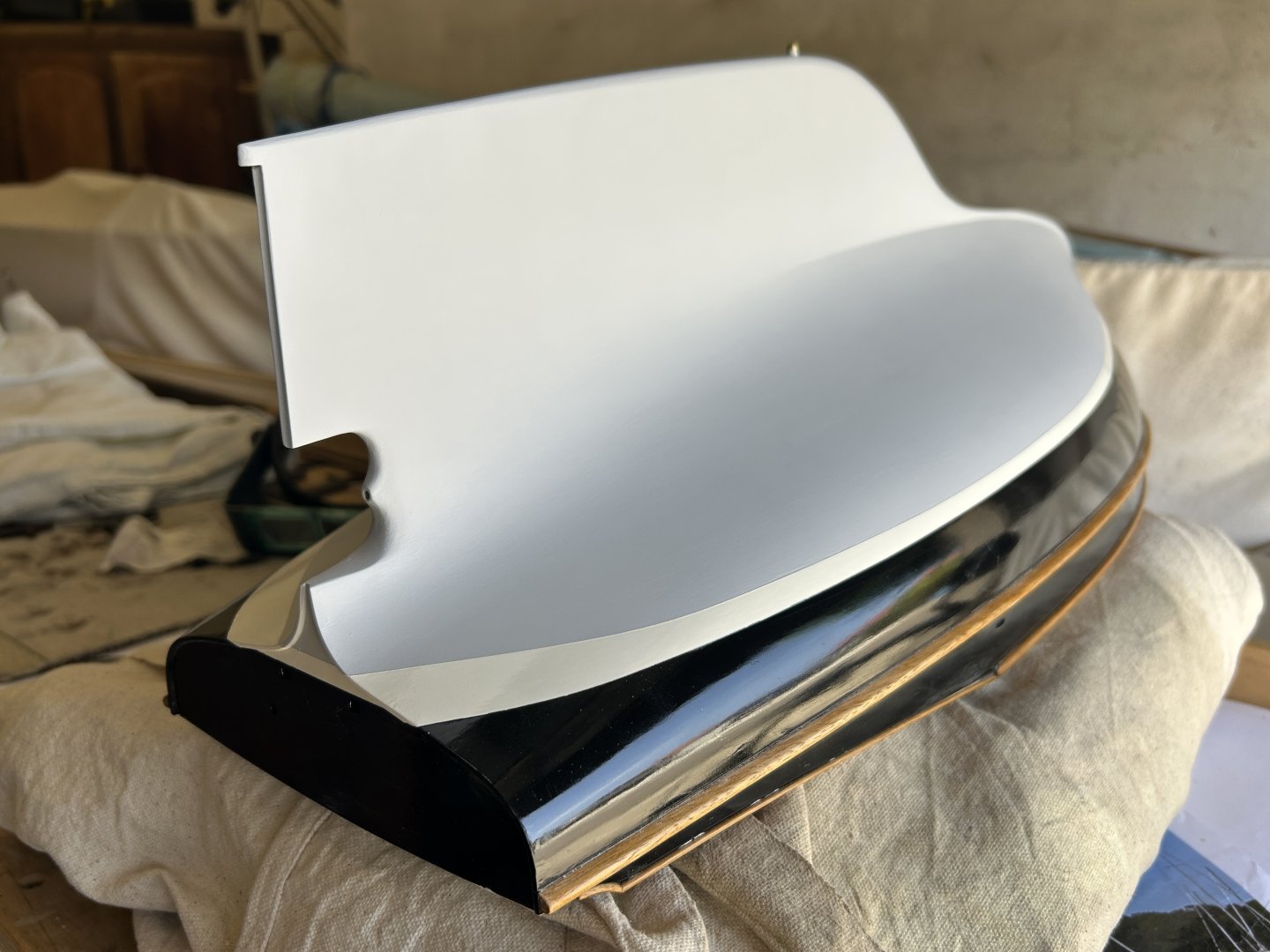
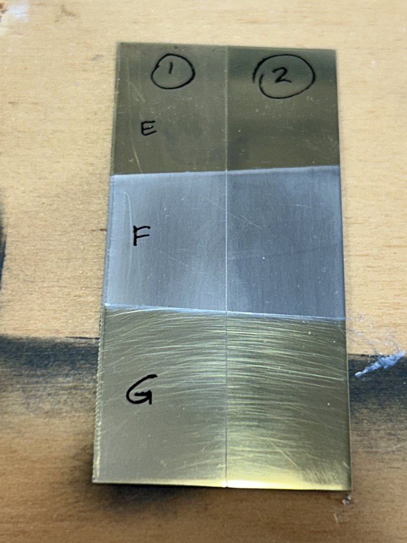
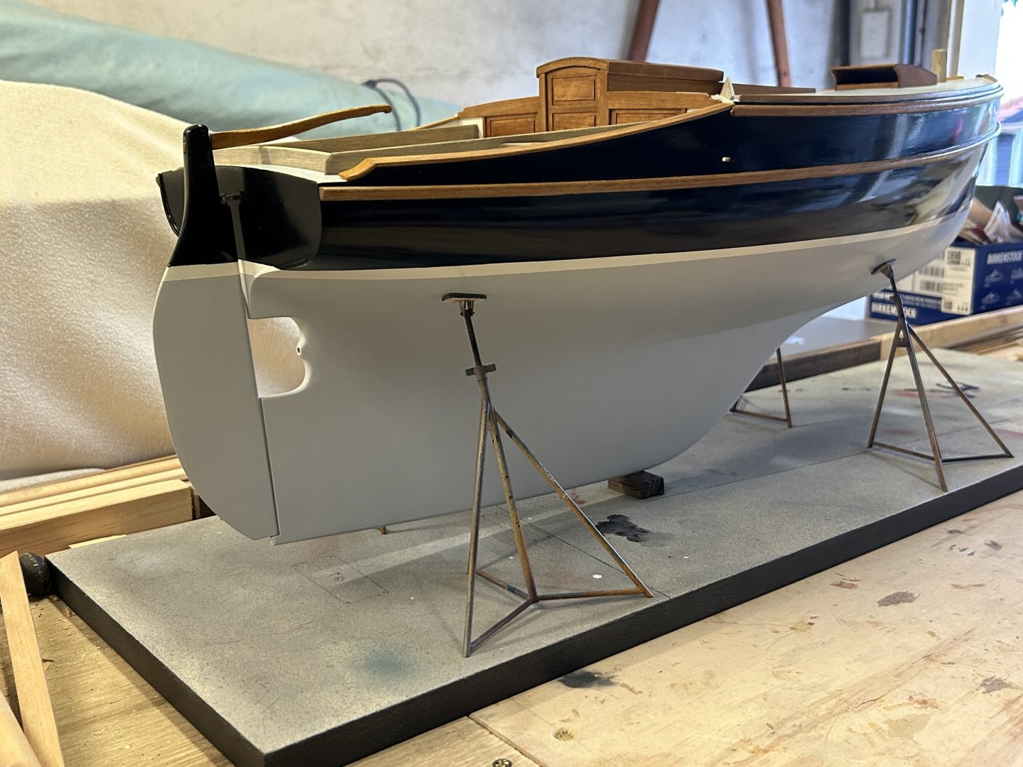
Thanks for the interesting exchange. Also interesting has been the recent work on the model. I painted the underwater paint, in matt acrylic paint. Initially I bought some Tamiya paint & there were 2 issues: I chose the colour poorly & the paint itself hasn't got good brushing characteristics. I found the paint wanted to gel within several motions of the brush, I'm used to being able to spend more time spreading the paint. I then recalled that the last model I used Vallejo, & also revised the colour. There is no doubt that Vallejo is superior as a paint, the brushing is beautiful & the overall result is excellent. Below if the paint samples I did - the initial ones were too green (Tamiya paint, on the right), & colour is such a subtle thing it just looked wrong. The final colour is the top left: colour number 176 mixed with white at 1:4. All the left board are Vallejo, using a combination of just white & a plain grey. 167 wasn't added to any of the samples. It's like silk, very impressive paint.... I decided to start putting metalwork onto the hull, starting with the rudder gudgeon / pintle. But first I needed to experiment a bit with this new wonder product - tinning solution. Eberhard (Wefalck) gave me some detailed & very helpful advice, I read it carefully & did some samples: on the photo below the vertical lines demarcate 4 different surface finishes on the brass, full height of the brass piece; A is plain brass; B is 3 minutes in tinning solution then rubbed with a natural fibre cloth; C is 6 minutes in tinning solution & rubbed; D is 9 minutes in tinning solution - & then because it wasn't visibly different to 6 minutes I used an all-purpose metal polishing paste to buff it. It was clear at this point that a nice silver shine which would closely replicate stainless steel was achievable & that the brass finish would be visible through the tin unless it was very smooth. Until this point I hadn't been sure what the tin colour would actually be, so i was happier than a dog with two tails.... Although I could see that the finish level on the brass did impact the finish on the tin, I wanted to know if a greater level of polish was possible & whether it was better to polish the brass before tinning, or the fine polish could be done after tinning over a fine but unpolished base. So the next test was one piece of brass half finished to a fine sand (1, to 1500 grit or similar) & the other half to a near-mirror finish (2). E is brass, F has been well rubbed with a natural cloth & G has been polished. The level of scratches that appears below isn't nearly as visible in reality, but the main point is that the polish level was very similar between the two 'G' samples. IE, a fine sand would be adequate, & then polish the tinned piece. **phew** So here's the rudder gudgeon & pintle, plated & polished: And installed (nb: the pin is like a nail that goes into the timber stock of the rudder & won't be removable - but it won't be visible that it is that detail): The black paint isn't looking great in the photos, it might have to be recoated at some point. One detail that was difficult to achieve is that the rudder blade has full 90º swing - usually for traditional boats you can't remove the tiller on a picnic day because the rudder stock being swung around by the waves will damage the boat's transom - so even if you tie the rudder off on one side, it's still takes up space otherwise useful for laying around... The 90º swing allows the rudder to swing without damage. It was difficult to calculate it out, but I managed it: Next, I came to accept that something more would be needed to give the model a very definite position on the struts, both fore/aft & also athwarts - a system that was simple, obvious & reliable. So, I made a 4mm brass pin & glued it into the underside of the rudder, & it will be pinned to a small hole in one of the timber blocks. The hole (visible in the timber block) will be stained, then glued into place. Note how the silky smooth matt finish on the underwater paint really shows in the keel photo. So, an overall photo with all this progress, the rudder blade really helps to complete the hull shape, & the antifoul paint looks nice: bye for now


-
Håkan, Good to see you posting again, you're doing a fine job on a complex build. I will keep following with great interest.
-
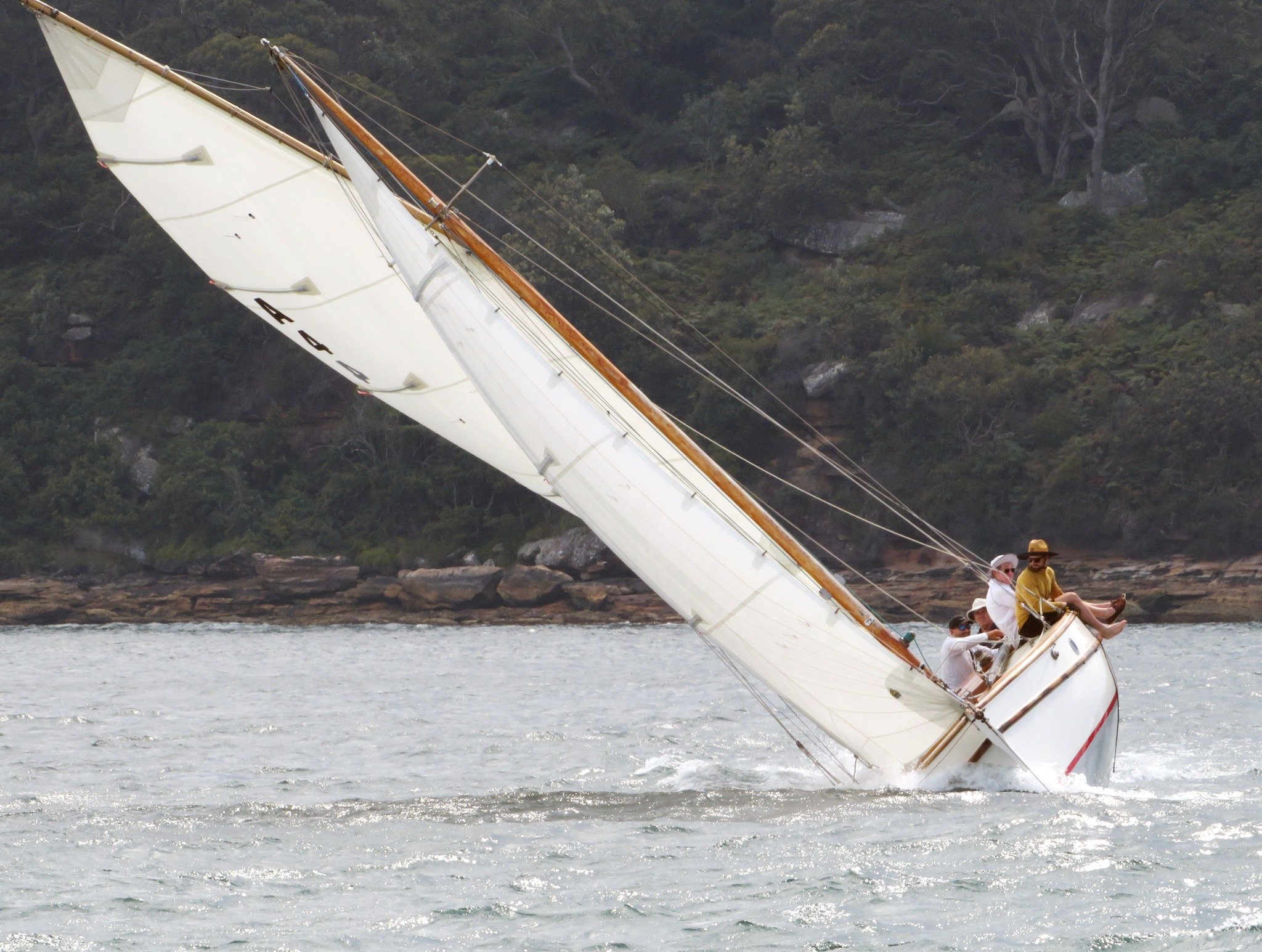
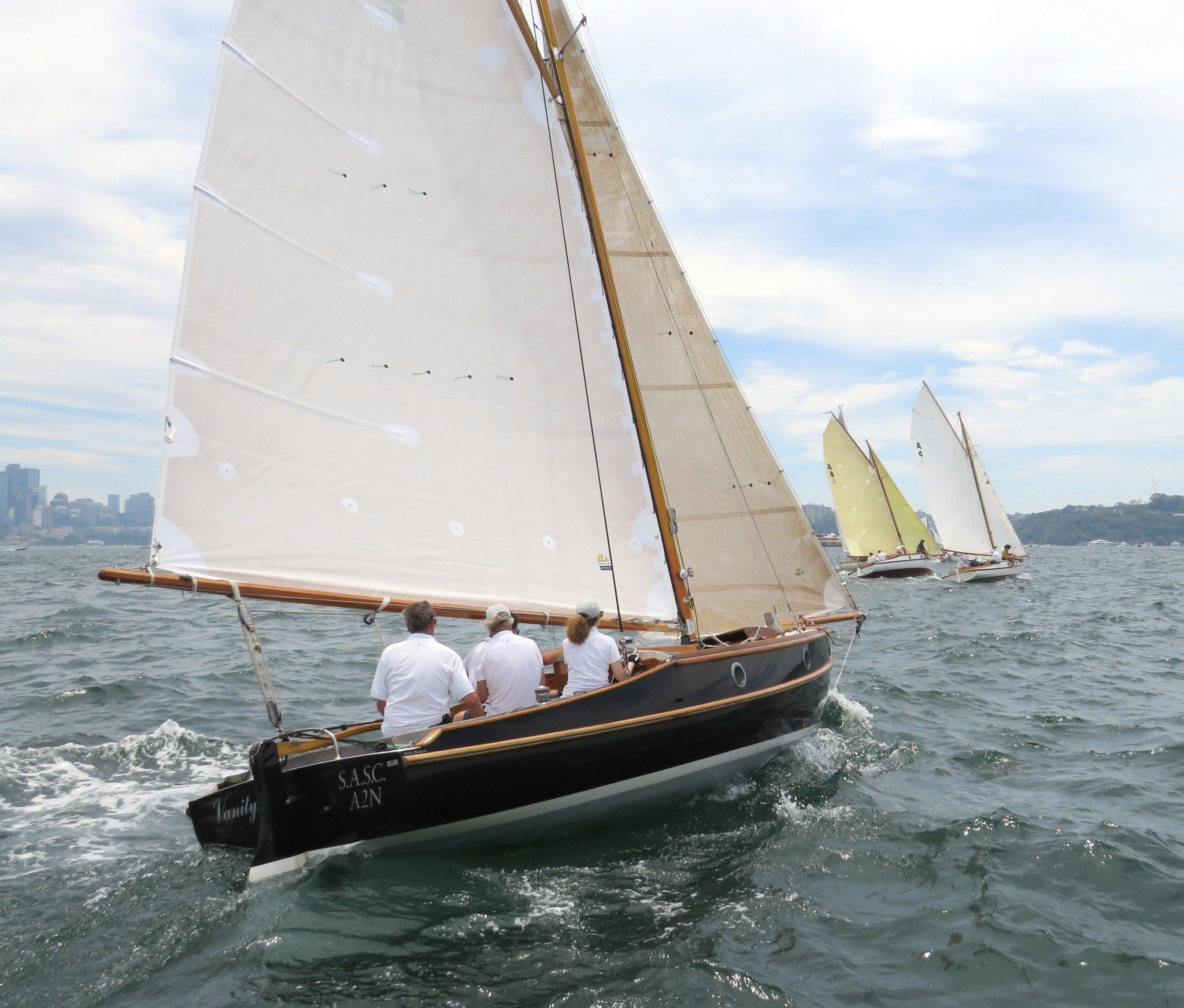
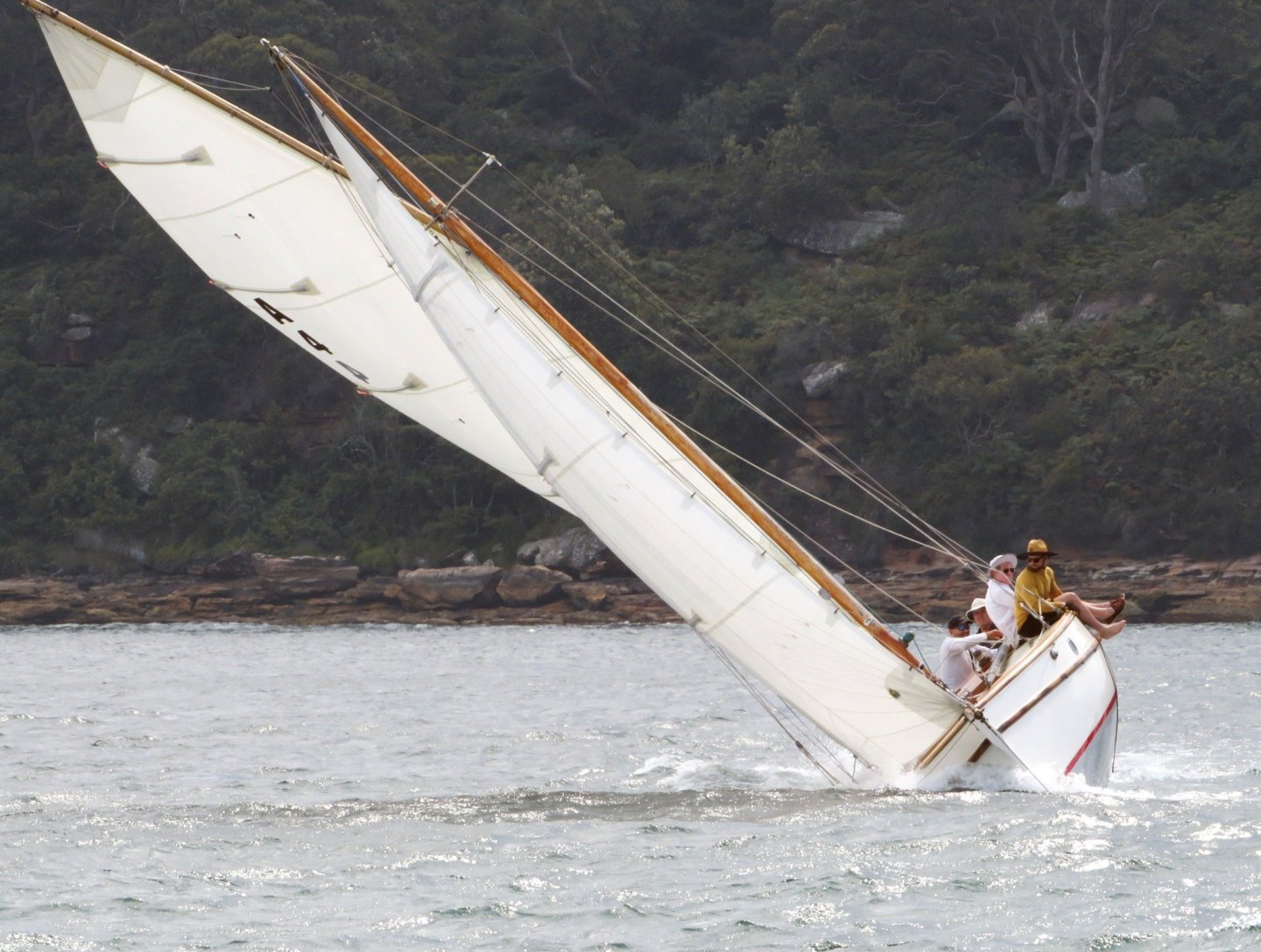
Hi Veszett, it's worse than you thought.....you can't see that here is a fifth crew to leeward of "the black cap", for safety we always have someone stationed to leeward. Hi Keith, I agree with that, but on balance over that race we were faster not reefed. Certainly for racing you're always looking for a way to get an advantage, & we tend to set the sails for the average breeze & do what we can in the gusts.
-
Hi Patrick, could you say more about the beeswax treatment process you use? thanks
-
thanks all, & off theme for a minute, a couple of photos from sailing last Saturday - the subject yacht on the start line: And it got quite gusty later in the day:

-
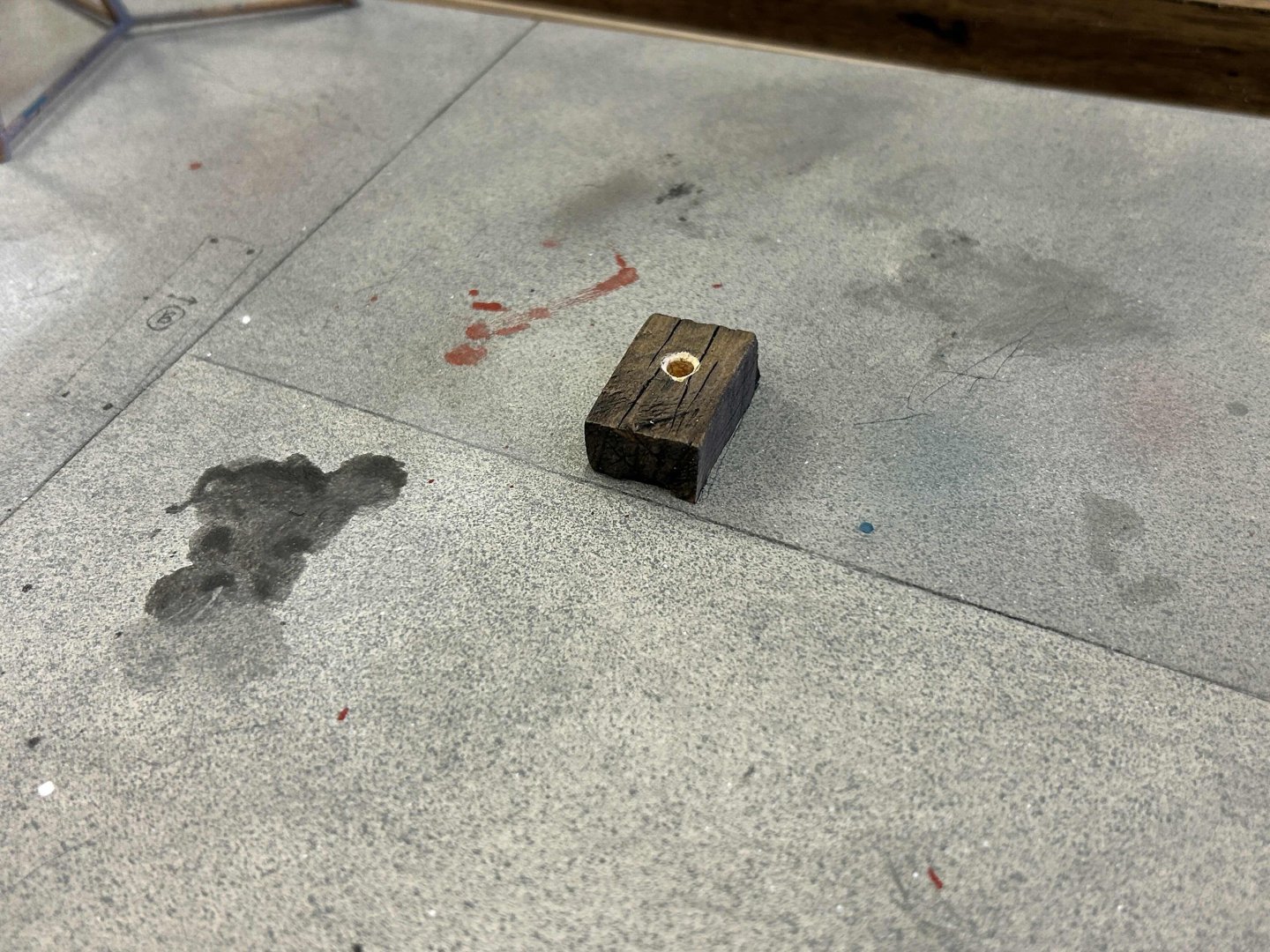
Some progress on the base - prompted by the approaching loss of access to my brother's air brush. So I hopped to it & did some weathering to the struts & base. The struts are possibly more weathered than the base, but I did want to wind back the intensity of the yellow paint & have some visible but not too obvious. And, I made some paint tin sized tins, & one large drum...the drum will become an important feature, it will eventually hold a label for the model. Stains on the concrete, plus the timber blocks have been weathered - not greyed but to an oily aged hardwood look. I scratched some deep 'cracks' in the timber with a spike, wiped on dark brown paint & afterwards some black into the cracks. The timber blocks are in position, just sitting there for now. And oops, someone left the black paint tin open, spilt it & walked in the spill.... but not too obviously, I hope. The struts definitely got "the full catastrophe".... still with the masking tape covering the 1mm felt on the heads. The timber support blocks for the keel: thanks,


-
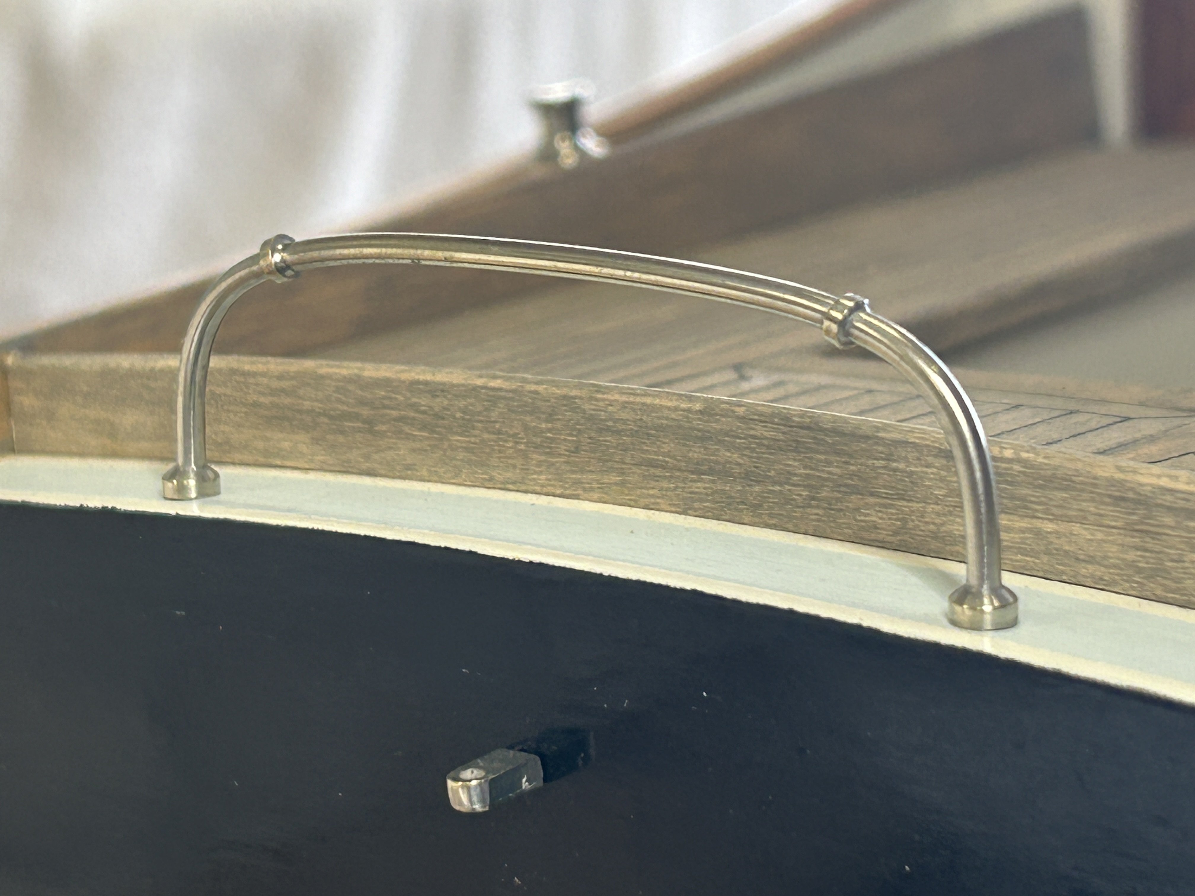
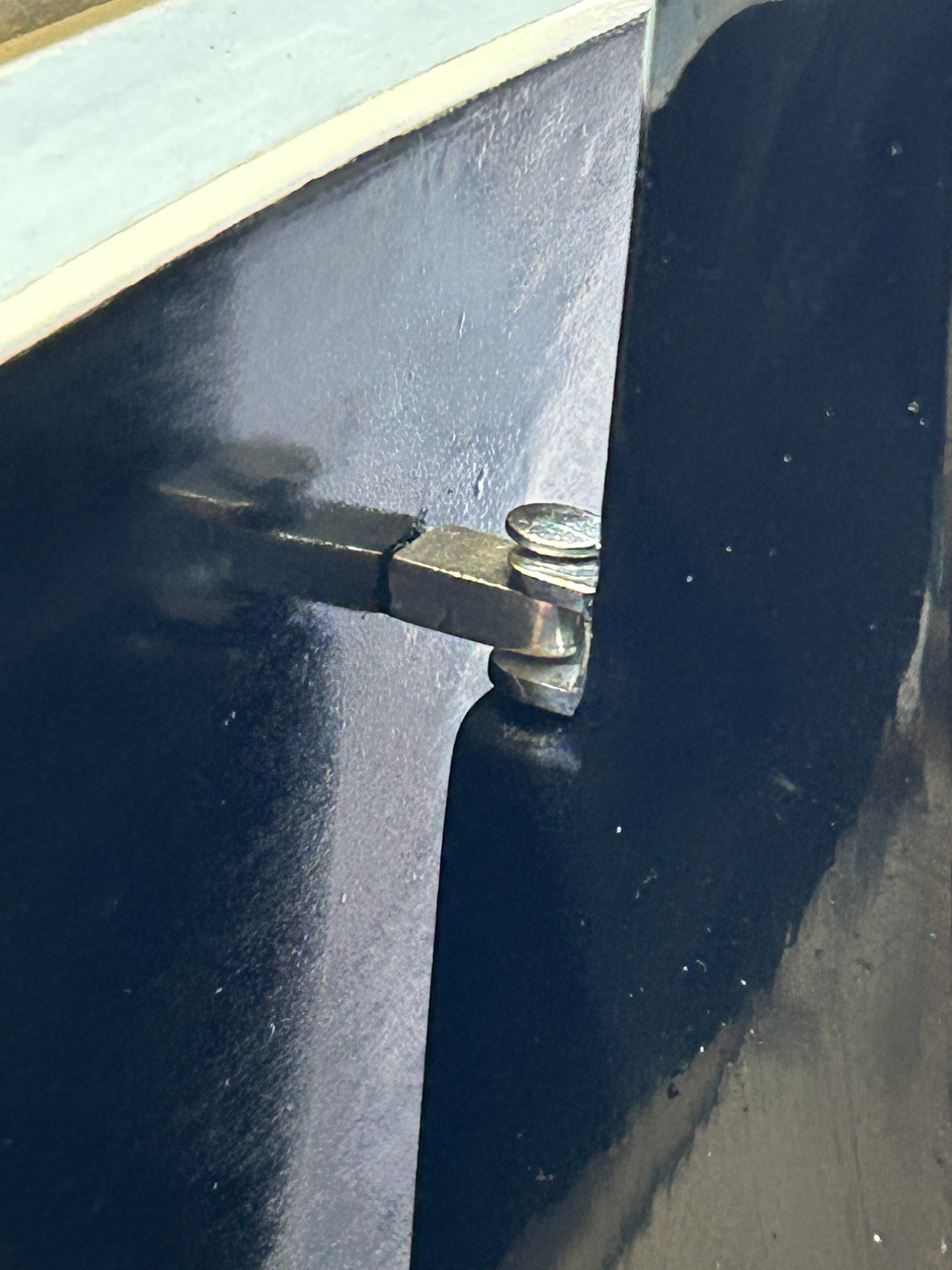
Alongside working on the metalwork details I am working on the model base - which replicates a section of boatyard hardstand area, as if the yacht is in for some maintenance. I showed the tripod support struts previously, they are now further progressed, painted & with their pivot heads & threaded extension system (not functional on the model). To help protect the hull paint, the heads have some self-adhesive furniture pads, sliced down to 1mm thickness (visible on edge here). You will notice the rough paint - due to some repairs etc, & I wasn't too careful about the process, to allow for roughness, which will be closer to reality for something really utilitarian like these. I haven't been concerned by scratches either. The 'bolts' through the flanges & threaded rod, are 1mm brass with the ends flattened by squashing the rod with pliers. And shown here with the heads glued into a fixed position, sitting against the hull. They will be rusted, oversprayed & more when done. Seen below with only 2 supports in place (there will be 4). The feet are pegged to the base with 1.5mm brass rod, that will be glued down for a secure fixing. The chain looks quite lightweight, I might have to look for something slightly heavier looking. It will also be rusted, etc. The keel will be packed with rough blocks of wood, which have been cut & are shown here approximately in position. They will get aged as well. And here with all four struts in place. It seems to be fairly stable. It's true that the actual struts would likely be located further apart, however the width of the base of this model is limited to the shelf depth of the future home of the model. I like the way it doesn't interfere with appreciating the lovely hull shape of the yacht. thanks!


-
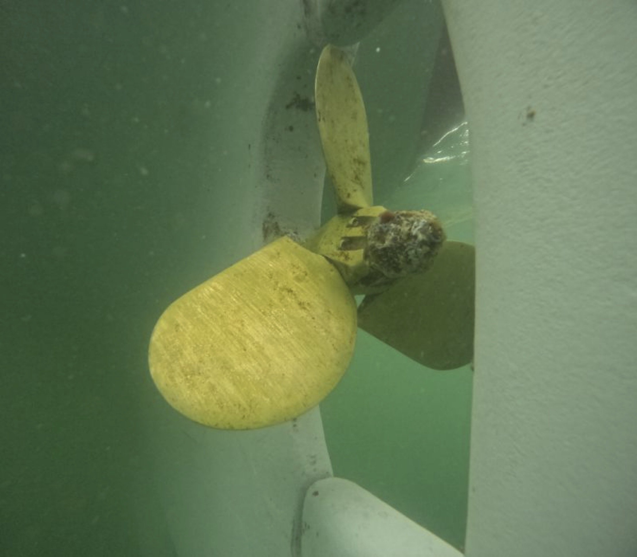
Hi Craig, thanks for the compliment, it worked out nicely. Re the loss of thrust, I suppose they factor a bit of extra blade area in when selecting the appropriate diameter & pitch etc. Another option is solved in another way by a local traditional sailing type, that are restricted to fixed props (ie: no feathering allowed), they use 2 bladed & put a spot of paint on the shaft so they can align the 2 blades vertically, so the blades sit behind the deadwood.
-
Hi Keith, yes soft solder & a Dremel brand butane torch. Hi Rick, by hand. It would have been easier if the trigger on the drill could be set, but I had to hold the drill firmly (braced against something), & with a finger on the trigger, then my other hand was free to try different angles with the blade. Hi John, for your interest here's a photo showing the blades rotated, on a slightly different model of the same prop brand. You can see how the lower section of each blade is quite thick. .

-
Well done, they must have been tricky to get the shapes right.
-
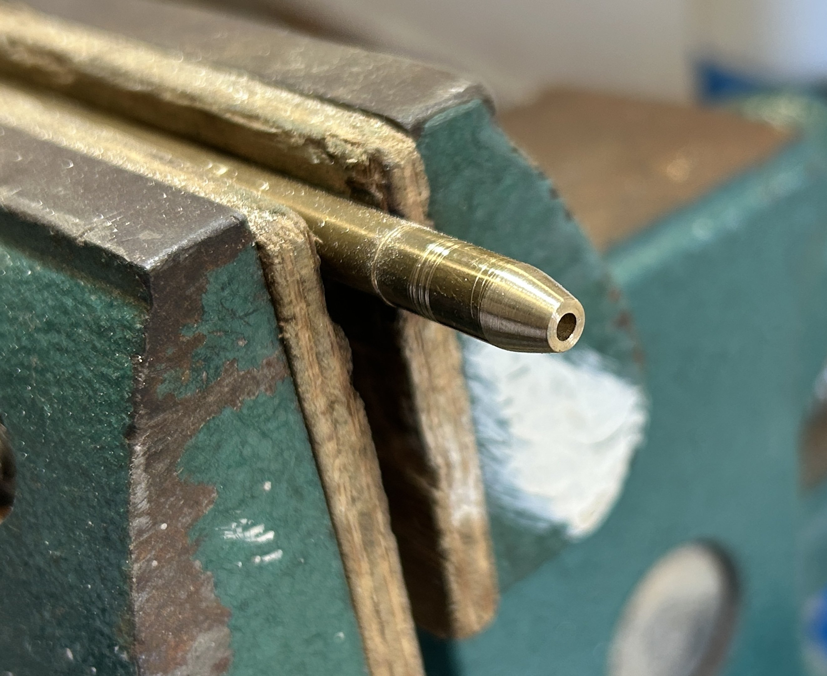
The propeller is a feathering one, & that makes it a bit easier to fabricate accurately, as the blades don't have twist. I think the way they work is that the prop shaft always turns the same direction, but when the engage reverse the blade angle rotates from the 'forwards' position to the 'reverse' position & so opposite thrust for same shaft rotation direction. Incredible pieces of engineering, if you ever get to see inside of one..... Here's the prop itself, with anode at the end & blades feathered: First, the main body of the prop is made from 6mm brass rod, drilled first to take the shaft & then tapered (bow end) by using a drill & rubbing the rod against a file, then sandpaper: The the anode shape was done, & the step using a broken piece of craft knife blade, against the spinning rod: The blades are from 1.5mm thick sheet, cut with a jewellers saw & the sanded to fine edges but full thickness where the blades meet the shaft. Soldered to the shaft: And cleaned up, & installed temporarily (nb: there will need to be a small washer where the shaft penetrates the keel).