Mark Pearse
-
Posts
696 -
Joined
-
Last visited
Content Type
Profiles
Forums
Gallery
Events
Everything posted by Mark Pearse
-
 Hi Steven, I enjoy the way your models come together. It might seem haphazard to you, but it seems thoughtful to us. And the mosaic in your last post is a very fine work of art, did the mosaics as art works inspire the interest in these boats?
 -
Very nice. They seemed to often (or perhaps sometimes) paint the top part of the mast. I'm not sure why.
-
That's an interesting looking magnifier, is that a drop-down second lens?
-
More beautiful work, & it's a satisfyingly large model. It has the feel of a real boat at this size.
-
Expanded polystyrene is an underrated material aesthetically, however I was wondering if you were going to do a stand, & what sort of design?
-
Hi Brinkman From a practical boat building point of view, if floors are fixed to the hull there should be some side gap, even if small. I haven't looked it up, but my guess timber will expand across the grain around 2% - so 3mm for a 150mm board. Floors can also be fixed into panels that are loose, not fixed to the hull - in that scenario they could be done without gaps. For a working boat, there's a lot of advantages to loose floors. Is there evidence in the example you cited, that the floors were fixed to the hull? PS The dark colour is beautiful
-
Congratulations Vaddoc, A gorgeous model & one that must have been a very demanding build. You really had to build the whole boat & it's a beautiful result.
-
And a very nice piece of metalwork too, a very believable look of wrought iron - could you tell us a bit about how you made it? It doesn't look like brass, but perhaps it is... In terms of the vessel, what was the bowsprit used for?
-
That's what we used for the kayak, it came with the kit (kayak was a Chesapeake Light Craft LT17). It went well. Do you use this on any models or just on your lovely small boat?
-
Hi John, Steve Thanks for the offer Steve, I have used quite a lot of epoxy. I built a small open gaff sailing boat some years ago (strip planked), helped my wife build a lovely plywood kayak, & myriad repairs on our boat Cherub. I'm using Araldite Super Strength for the model. Per ml it's expensive, but the tubes make it easy to proportion a serving, & the quantities will be small. Also, it is far tougher than it used to be. I have tried West System, Bote Cote, Norglass, Epiglue, Aradite & the SS Aradite is almost the equal of Epiglue. The 5-minute is good for some uses, but that doesn't include planking this model. For a model, I would only consider an epoxy that was pre-mixed with fibres, that is a 1:1 ratio, & available in a convenient form in small quantities - other ratios wouldn't be practical for the quantities we typically mix. So that cuts out most of the above, & I'm not a fan of Norglass epoxy. Lastly, it is widely available. Previous models I mainly used PVA, especially Titebond. Do you use epoxy for models?
-
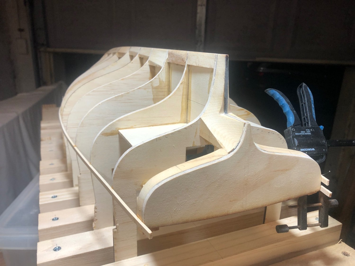
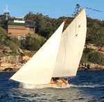
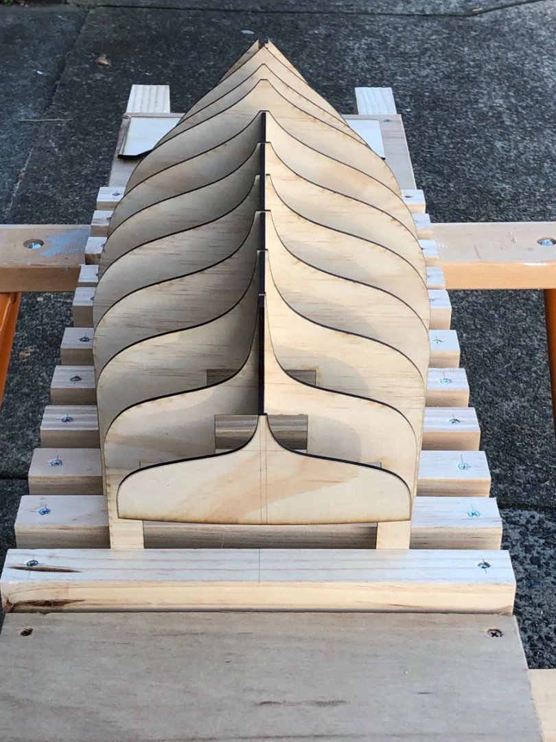
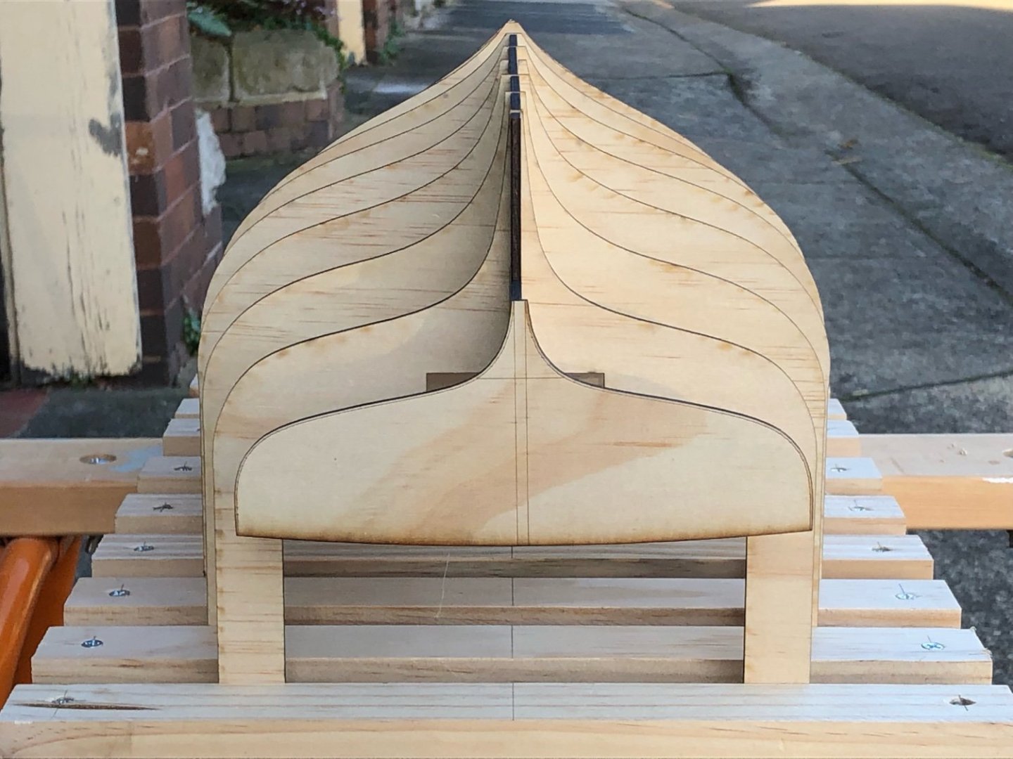
Since my lost post I have been preparing for planking & adding a keel. I have made the front inner part of the stem; put solid blocking between the moulds (mainly to give the keel something solid to be fixed to); some solid blocking around the propellor cutaway (the final shape is best made from solid timber, so again the blocking gives something good to fix to); plus some timber next to the transom, just so the glueing surface is greater. I did some fairing of the moulds, it's not yet 100% completed but the lower parts of the hull, towards the gunwales, are pretty accurate now. The hull is a raised decker, so the topmost full length plank is from the top of the transom, which is lower than the main deck line. I decided to do this plank first then plank up & down from it. The process was influenced by the fact that it won't be traditionally planked, because this actual yacht was built strip planked (ie: wood epoxy composite). I've realised it does give more flexibility on planking. Anyway, the do the first plank without pinholes in it, I pinned a temporary plank on each side, but 2 planks distant....2 planks so that I didn't glue the pinned plank to the moulds. Subsequent planks can be clamped to the ones already installed. You can see it below, the glued plank is not pinned. Spacers offset so they didn't glue to the hull. First plank done, some slight imperfections, but within 0.5mm sanding depth. Planks are 2mm thick, replicating the actual strip planks of 25 x 50mm approx. I used epoxy for these two planks. I hoping that I can use it for all the planking, including the edges (ie: plank/plank). I'm hoping that it will give a more monocoque hull so the planking lines won't be visible. Strip planks don't run in the natural way, so seeing the trace of them will be off-putting, & given the hull colour is black detail issues will probably be more visible. all the best


-
Hi there Håkån That's an interesting way to plank it - it looks like you have two mirror-image jigs. You do a bit of planking one side then flip the model into the other cradle, clamp the keel & do some planking on the other side...? I like the way it means you can clamp the keel straight each time. I haven't seen that before, could you explain why you are doing it this way?
-
Hi Silverman, as you raised the question, I looked & I do think that you are right - the lower part of the two centre knees are a bit heavy. Remembering that their job isn't to support or strengthen the beam itself, but to brace & strengthen their connection to other members. The part of the knees sitting on the top of the central beam probably need to be more slender than the beam. Perhaps also the aft knees a bit as well. best wishes, looking superb
-
That thing to hold narrow timber for planing is great. Do the wooden cams stay in place when tight?
-
Hi there, Nice to see this lovely model back on the bench. I think you should go with your instinct regarding the bowsprit. The posts don't make as much sense for a number of reasons, but your solution is simpler & just looks right.
-
Lovely. You got the deep & squarish forefoot of the bow, apparently it's so the boats can drift well. If the forefoot is too rounded they don't hold a drift abeam to the wind, the bow blows faster than the stern.
-
Hi Steven, A subject close to my heart, they are wonderful boats & I race against them quite a lot. For once I have a bit of knowledge - the fish they went after is Barracouta, & not related to Barracuda. The bowsprit question I had to look up in the wonderful book "First Home, The Couta Boat & Victoria's Couta Coast". I had assumed it was to get a larger jib, as sailing performance was important - the first boat home got the best prices for their catch. This is partly correct...on the curved bowsprit (on Coutas called the jibboom) the book says "The early boats ... had little or not bend in the jib boom. Later, the larger boats ... had higher bows & more sheer. Extra bend was put in the jib boom to get more length in the jib & to improve the appearance of the boat." The book has a lot of details, if you want anything you could post or PM me. The model is looking lovely, & I shall follow with great interest.
-
Hi Keith The lines drawings show very careful & patient work, they are a credit to you. It's a fascinating hull. Like a sailing boat, but not a sailing boat.
-
Hello Håkan Greetings, this is a very special build of a remarkable yacht. I haven't been following the forum closely recently, & this shows what I've been missing. I hope that you got some good sailing in during your summer. Best wishes & I look forwards to updates.
-
Hi Steven Have you come across the photos of Alan Villiers? In the 1930s he spent some time on lateen rigged dhows. No doubt many differences, however it's just possible some the the technical questions might be helped by some details that are visible. His photos, if you haven't seen them, are very good quality images.
-
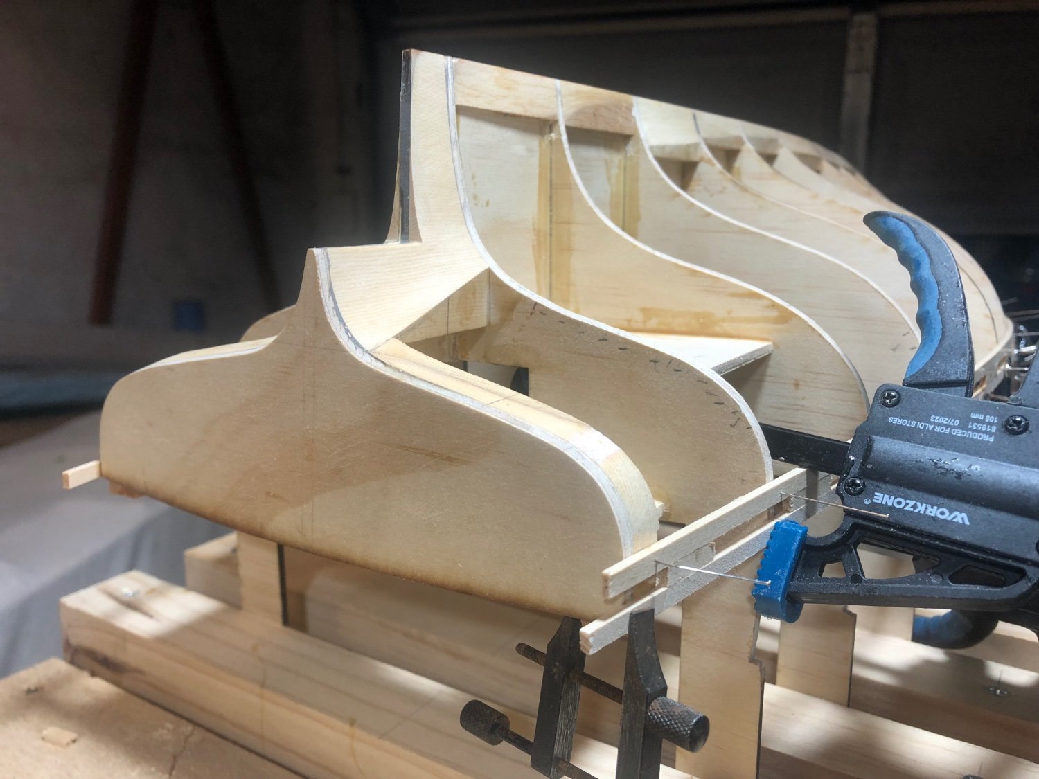
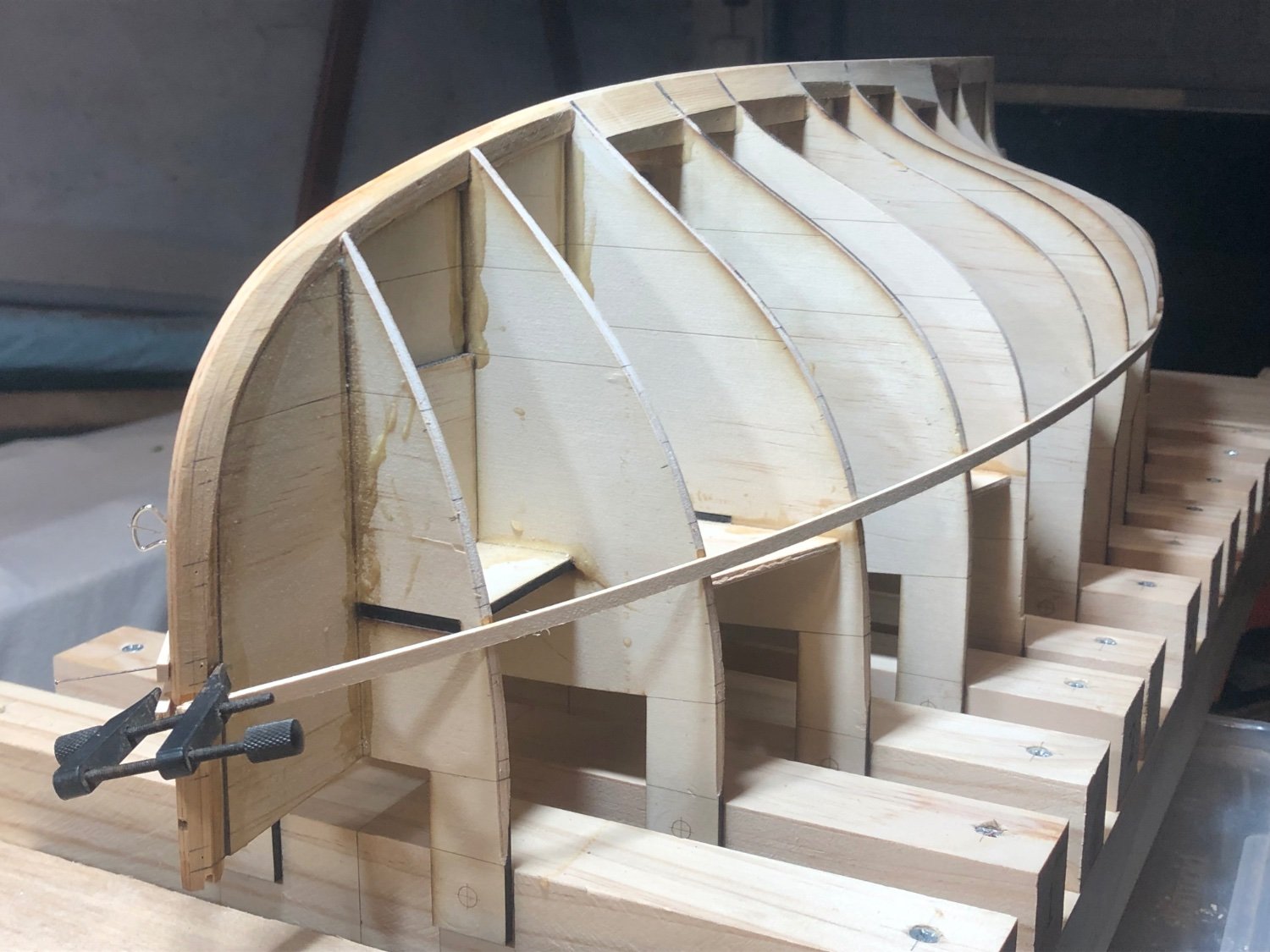
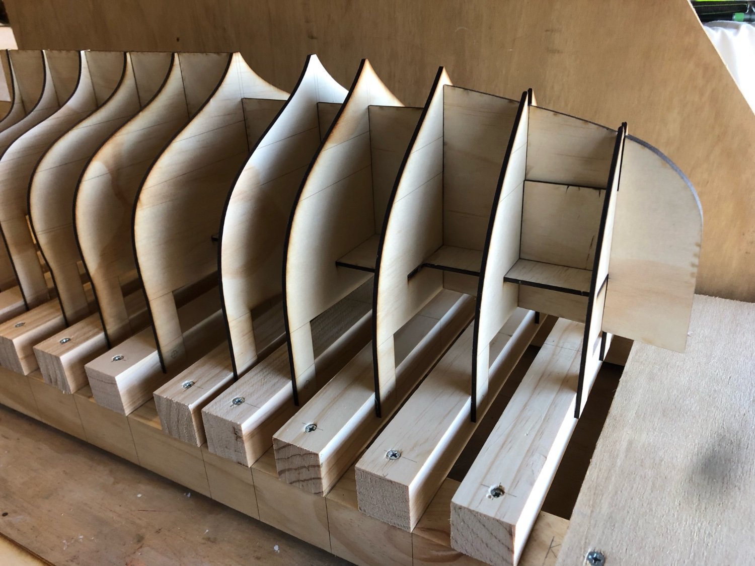
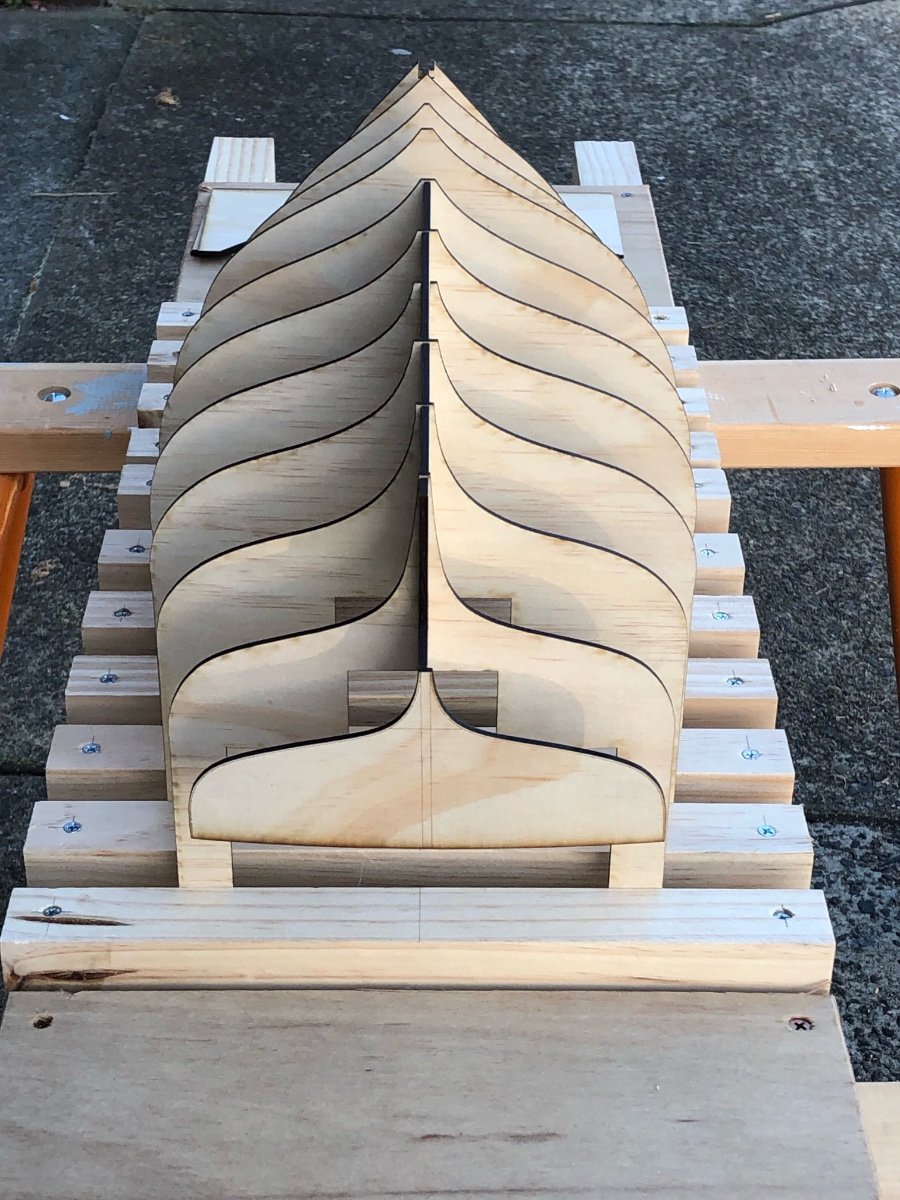
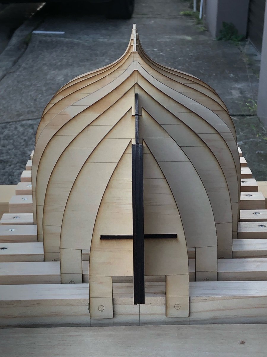
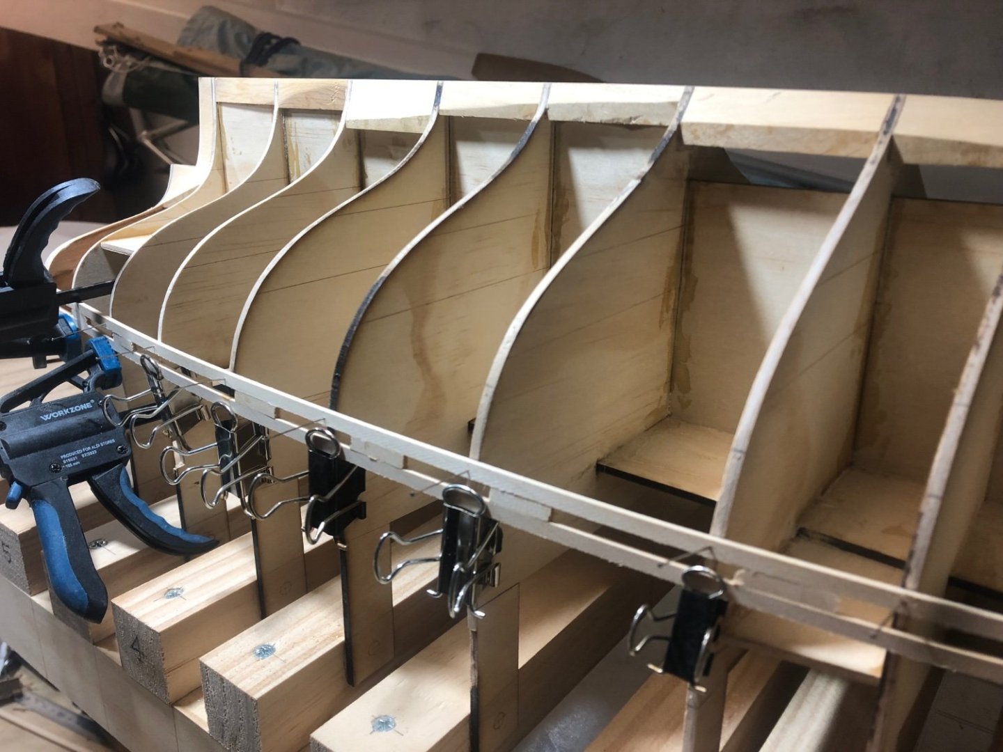
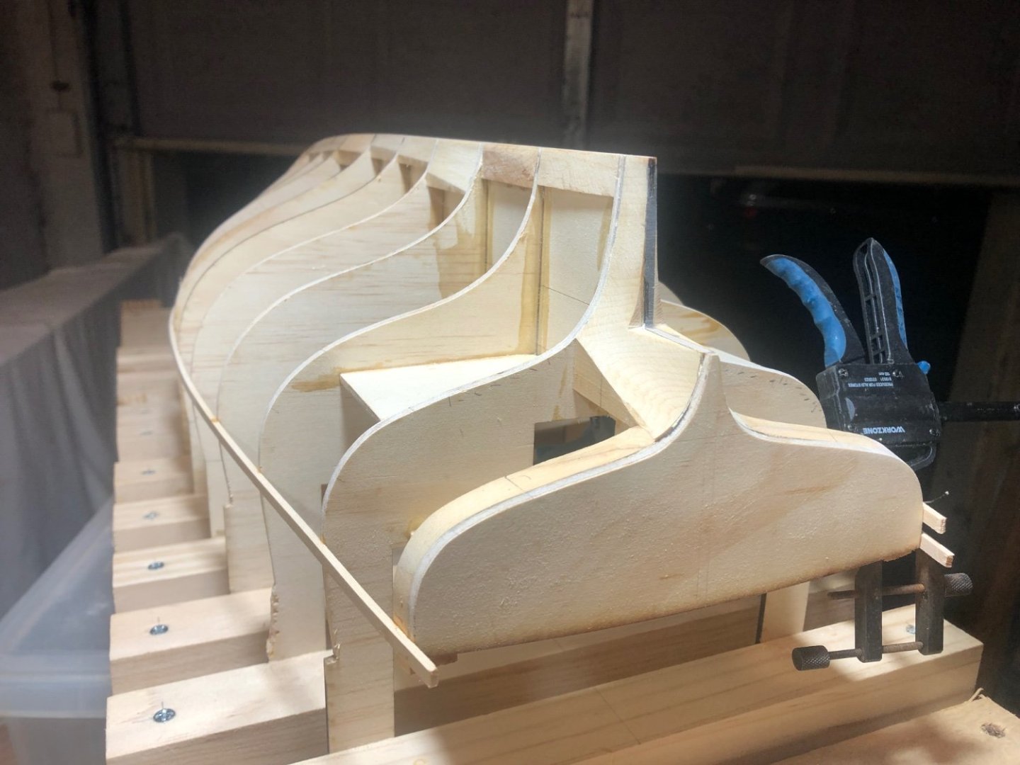
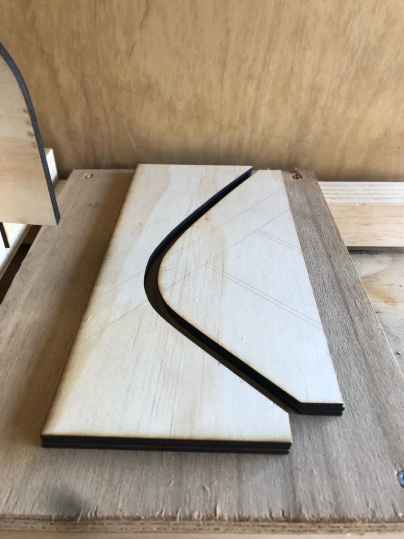
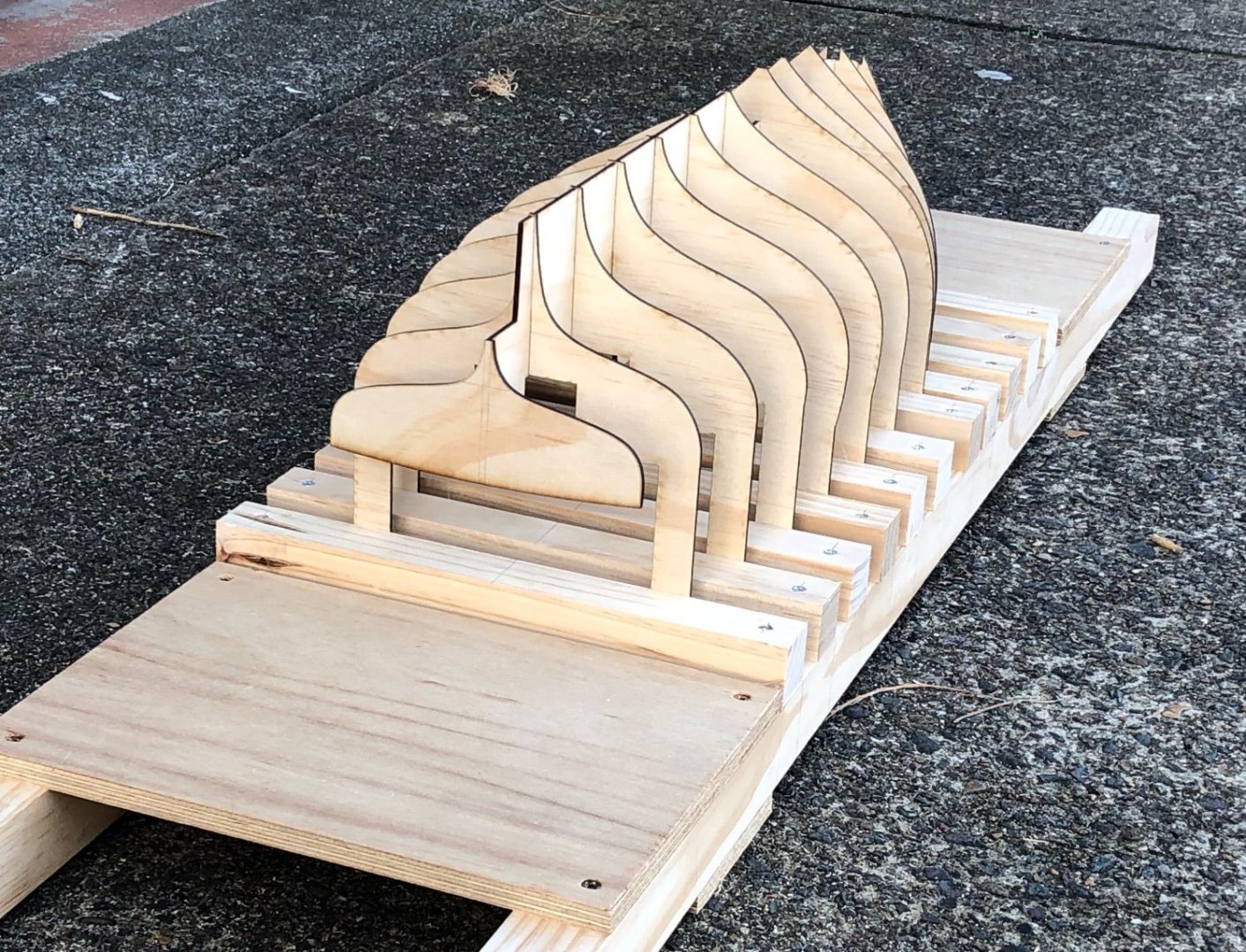
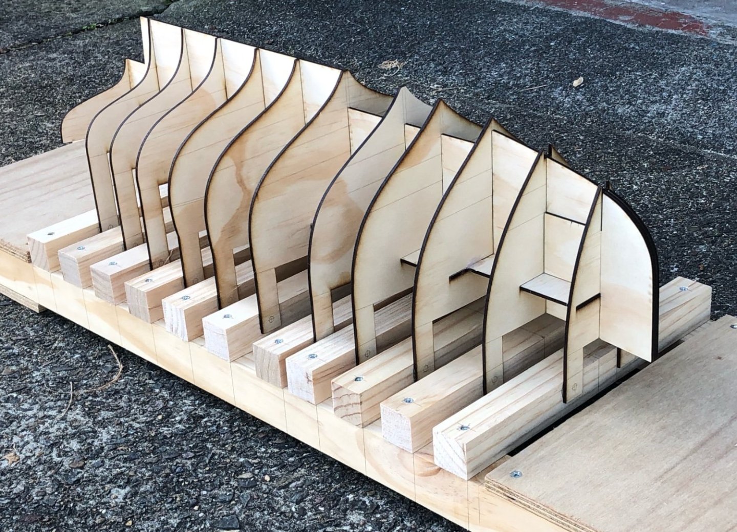
Good progress, I've cut the moulds & have started assembling them. It's always exciting when the model starts to go from 2D to 3D... But first I have to make some comments that may assist others who choose to cut their own moulds from laser cut drawings they do themselves: the assembly was more difficult because when I worked out the shapes to have cut, I didn't include the building frame in my thinking. Assembling them was more complex then it needed to be. Anyway, it worked out ok. I originally planned to screw the moulds to timber strips to hold them, but it's now quite obvious that if the moulds interlock in the way that these do, then screwing them together wasn't possible. So they were all glued to the main building frame beams with PVA. The photo below includes a detail of the bow extension - the laser cutting bed was only 600mm long, so there were some extra pieces at the bow. This gave an opportunity to make the bow thick enough for the inner stem to land on & sit against. you can see how the front moulds include a cutout for the 8 x 8mm inner stem. You can also see the lateral pieces to give rigidity in the planking stage. The inner stem will be glue laminated by the jigs I cut, also by laser. 3 thicknesses of 3mm plywood. The pale lines will help to position the final piece. The transom piece has just been temporarily tacked on with hot-melt glue. The plywood is still loose, although I pinned it with dogs of hot-melt glue to stabilise it. In the next few days I'll glue them with epoxy glue.....once I've had a good long look at the frames to see if I need to tweak anything. The uneven spacing of the moulds has a reason - the lines drawings I got were the actual moulds from the boat's build. The moulds were used to shape a series of glue laminated frames that were not evenly spaced. The hull was strip-planked (timber/epoxy composite construction) & there are only 10 or 11 frames (or ribs) instead of the 60 or 70 needed for traditional construction. So, because they were the only lines drawings I had to use that same spacing, which was to locate the frames in relation to hatches, mast etc. thanks,


-
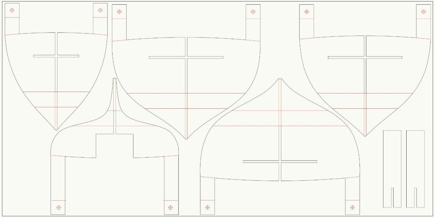
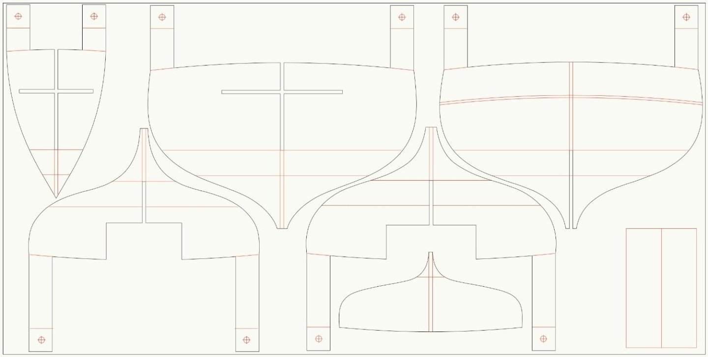
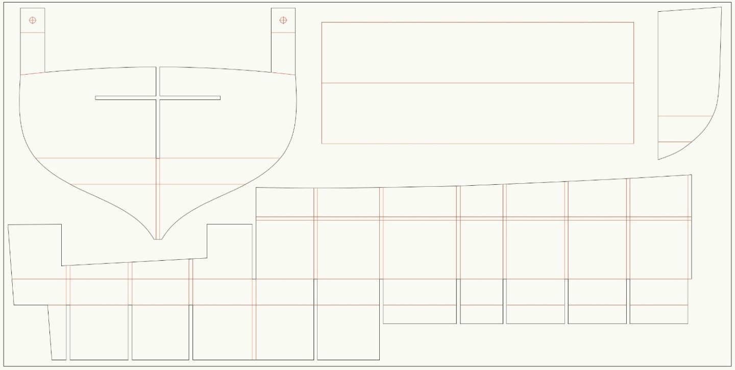
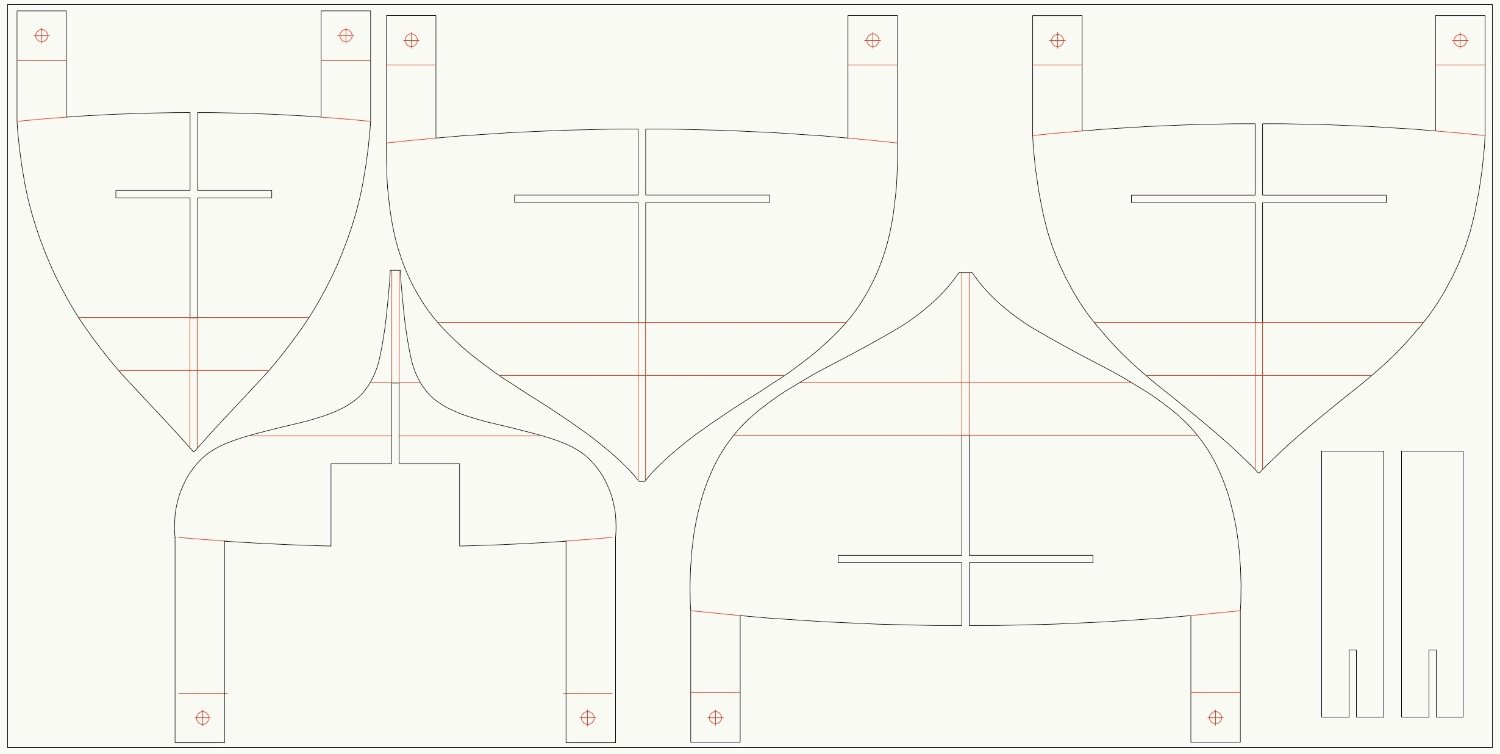
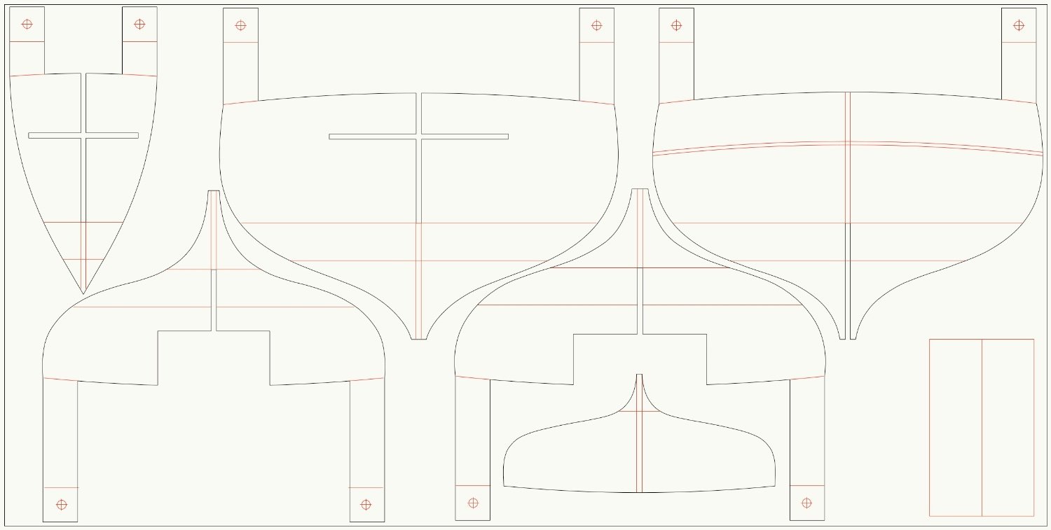
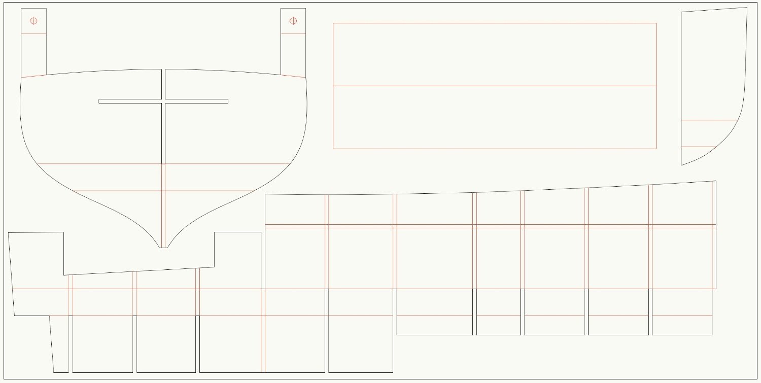
Thank you, I should be able to cut next week, below are the cutting plans. There's something I need to check on the weekend. Black lines are cuts & red are scored lines. The perimeter boxes are the bed size of the cutter. The glued up moulds should be quite rigid, but I think there's still going to be good reasons to build it on a frame, so I put legs on the moulds & more setout lines.