Mark Pearse
-
Posts
836 -
Joined
-
Last visited
Content Type
Profiles
Forums
Gallery
Events
Everything posted by Mark Pearse
-
 What an interesting vessel! The previous post with the roof on looks so nice.
- 110 replies
-
- 3
-

-
- Paddlewheeler
- Ballarat
- (and 3 more)
-
Hi Dick, The amount of timber in the ships of this type & era is an extraordinary thing to contemplate. With the deck timbers on this vessel, what actual size were they? (also, were they usually Oak?)
-
Hi Steven, I hope you aren't in danger with the current bushfires in your area. Best wishes on that.
-
Hi Craig I hadn't seen this log before, I clearly need to browse the forum a bit more. She's very nice. Is that a heavyweight sharpie?
-
Thank you Håkan, that's a lovely yacht, & thee S & S dna is evident. I have been lucky enough to do a motor boat cruise through the Finnish SW archipelago, & we went as far as Åland (Avenamaa), so have some experience of the rocky aspect. It was slightly shocking that some rocks 1m or less deep can be unmarked.....but I suppose you get used to it. Avenamaa of course has historical ties to Australia, being the home of the last sailing trading ships between Europe & Australia, as late as the late 1940s, I think. all the best & thank you for the minor detour
-
it would be nice to hear what sort of vessels you can & like to sail on, your part of the world has a rich maritime history
-
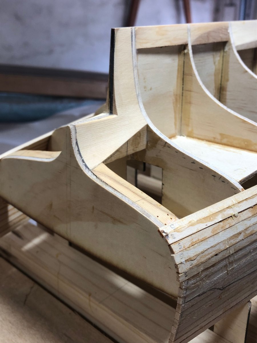
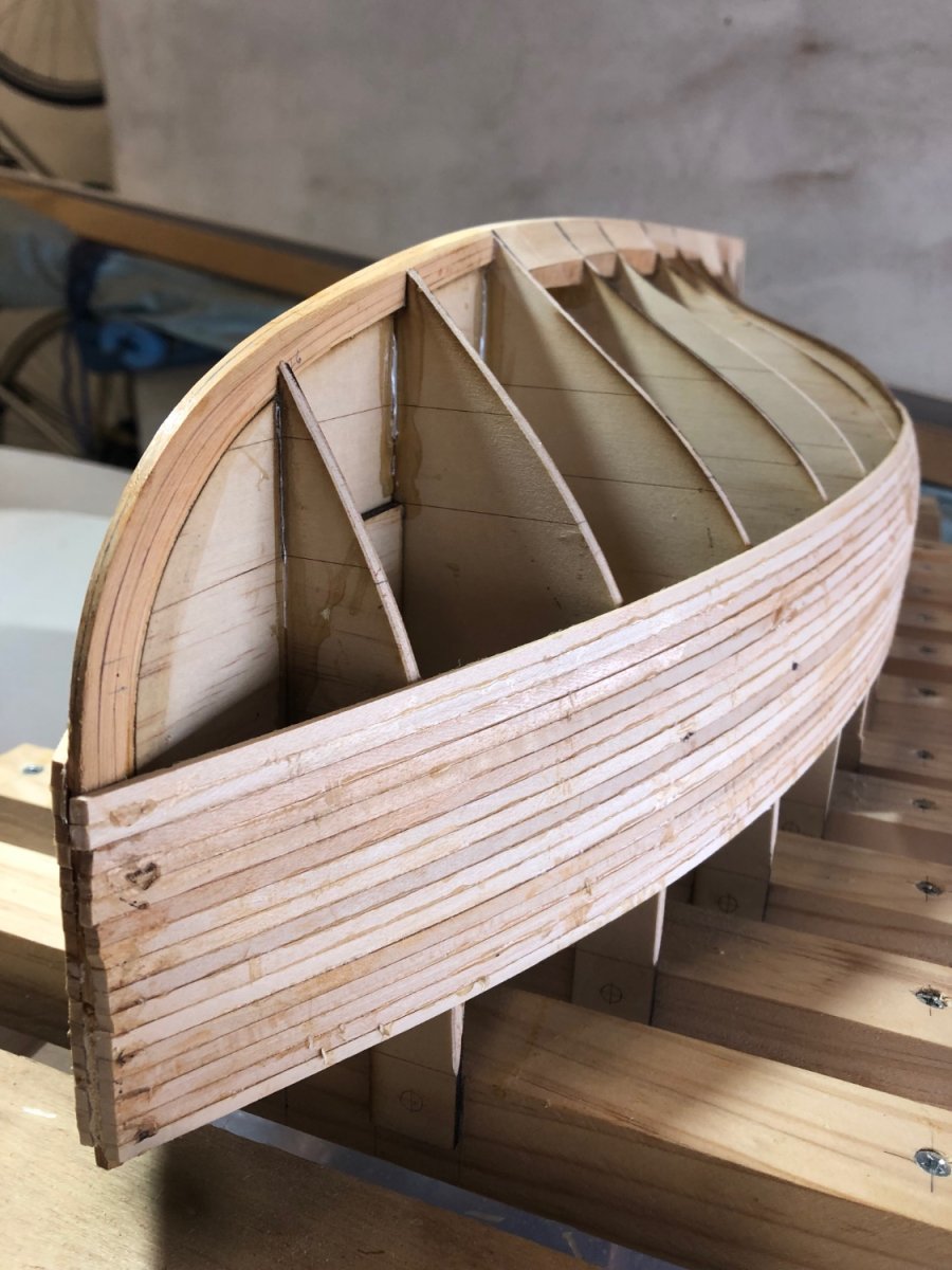
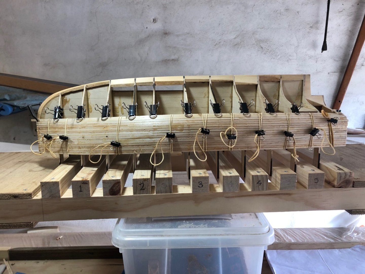
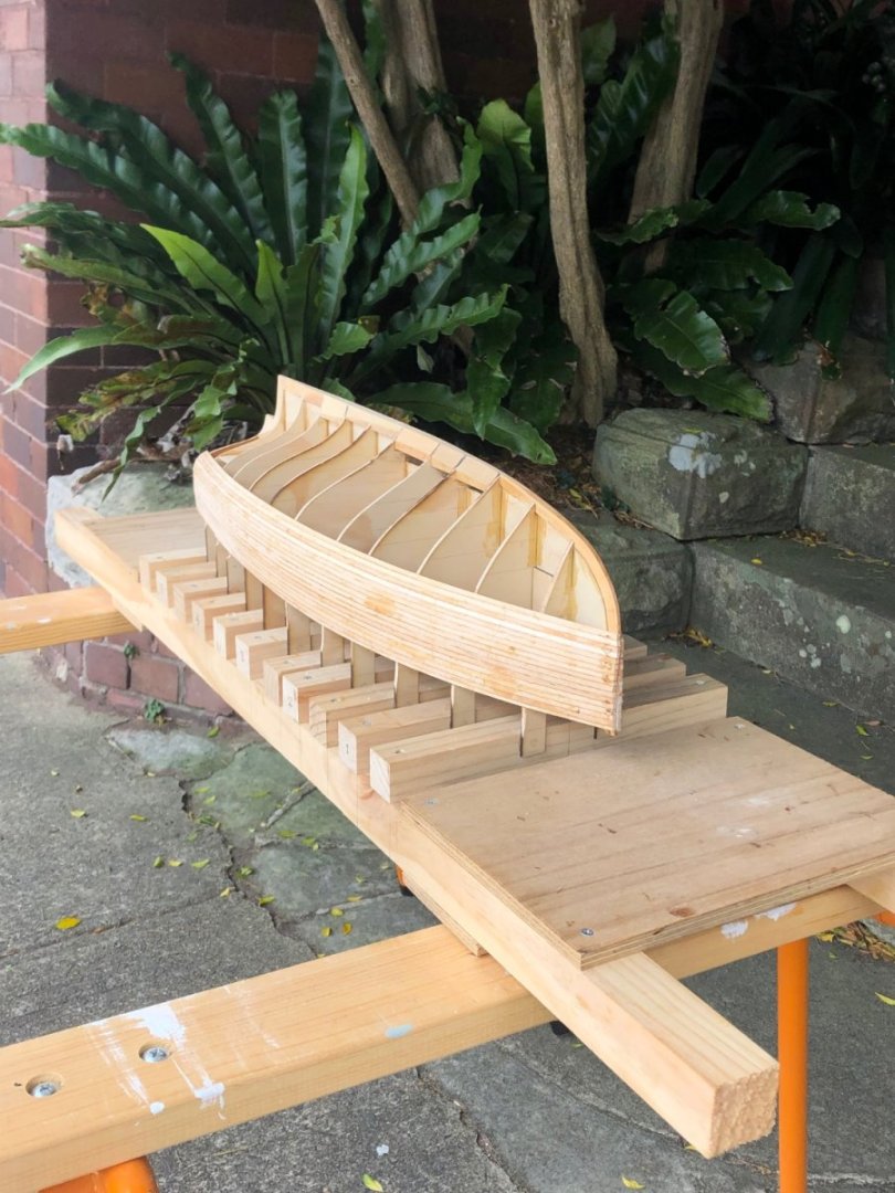
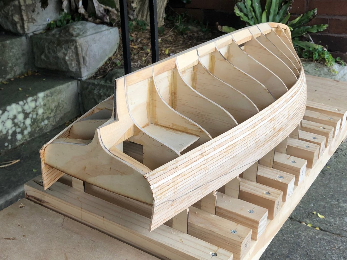
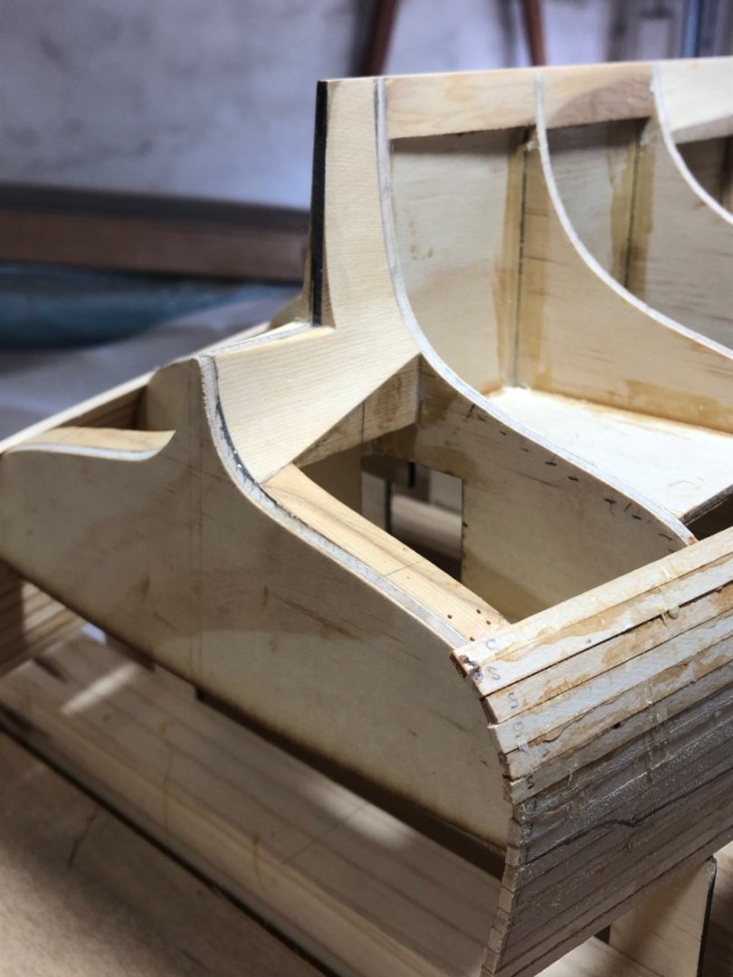
The model has been progressing, but the planking is pretty slow, but it is getting there. The simpler nature of a 'strip plank' style hull does reduce the technical difficulties a lot, but balanced by the relatively narrow planks. And the previous planked model was using Huan Pine, which is very supple, this is Basswood / Limewood & it's much stiffer. The lovely lines are appearing, although it's not so visible in the model yet - the scallops from the gunwale line around the cockpit hasn't been cut yet .... & it's probably normal anyway. This one shows the technique: bulldog clip clamps to hold the planks to the moulds & rubber bands to assist pull the planks down to the previous plank. The gunwale scallop at the stern is marked approximately in pencil & will be cut after the model is fully planked & removed from the building frame. I'm starting to use the heat gun to put some pre-twist into the planks. The epoxy is messy, but all will be forgotten once the sanding starts, but for now another few weeks of a plank or two per day. thanks

-
Hi Steven, I can confirm it works, I used acrylic paint (tinted to suit the colour I was after) plus 10-15% PVA, then rolled on with a 100mm roller. There's some more details starting from about post 344, linked below. I used a 6H pencil for seams & finished with clear matt spray finish. 5 years later & there is no sign of any delimitation or discolouring.
-
That's wonderful Håkan It's a very nice hull shape, the water exit lines are sweet.
-
Your post raised an issue of modelling accuracy - not accuracy to history but how close to square, how consistent in size & shape, etc. My boating experience is with smaller traditionally built yachts, & even boats that were built by recognised boat builders of the day have many inaccuracies. It's clear many things were set out by eye, & quickly at that. Hatches well out of square, portholes not aligning on each side of the hull..... I suppose I'm pointing out that what you described is probably more true than a high level of accuracy & consistency.
-
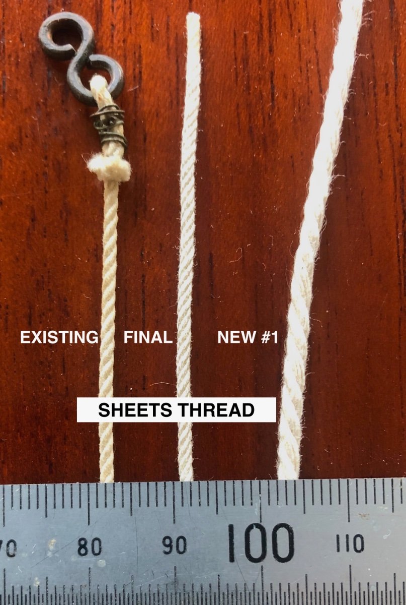
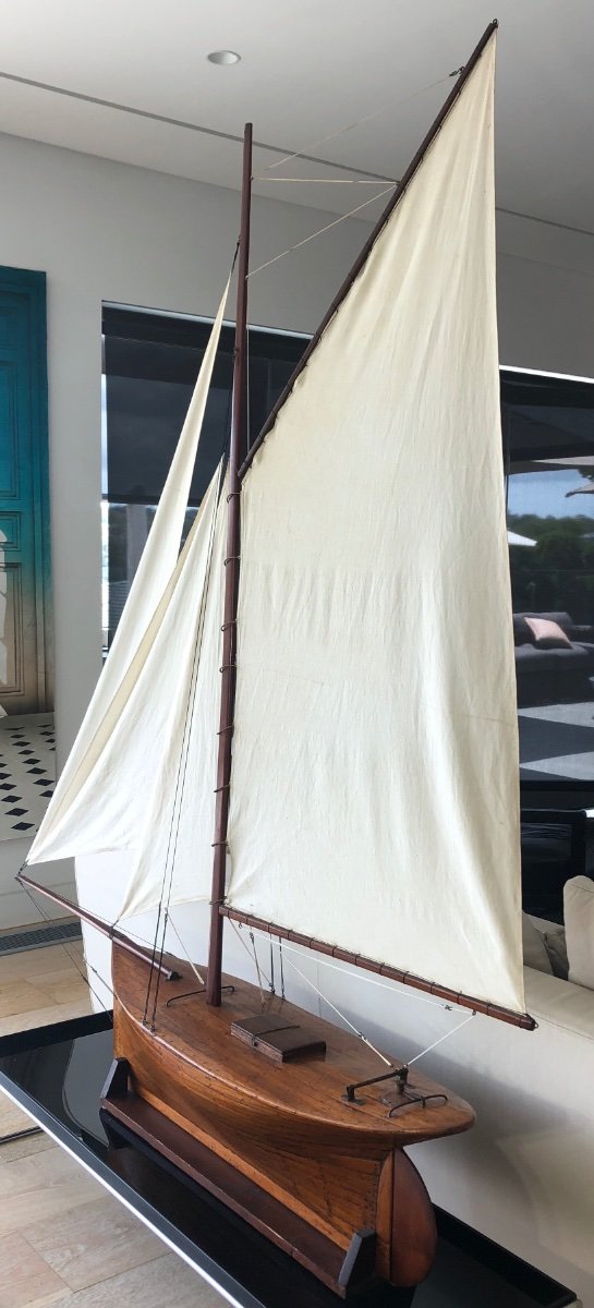
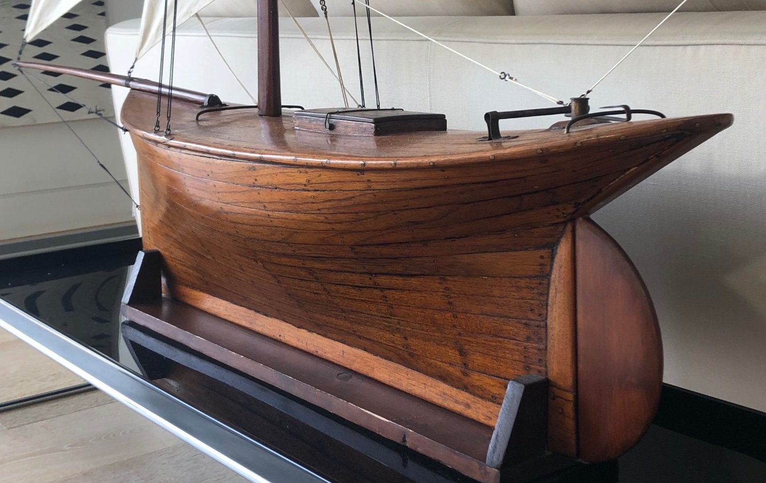
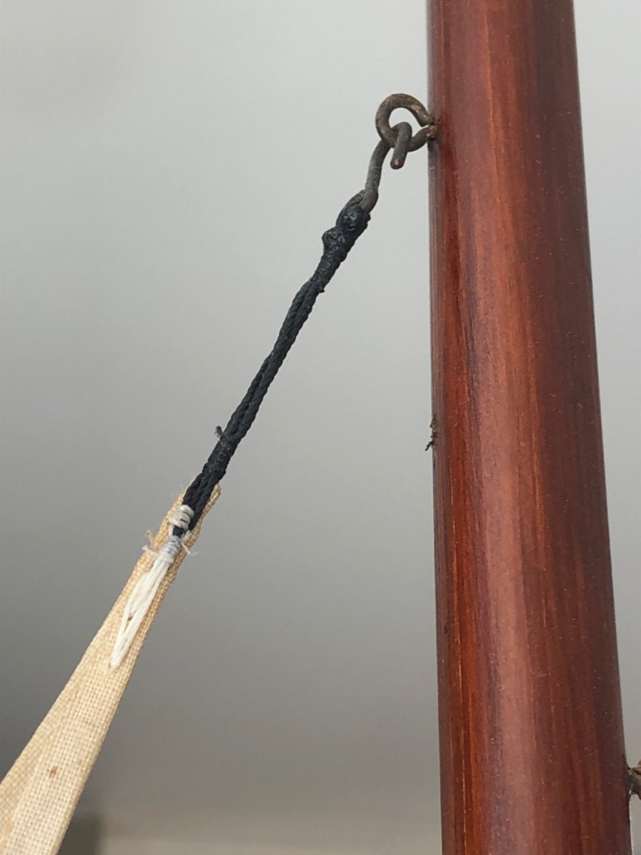
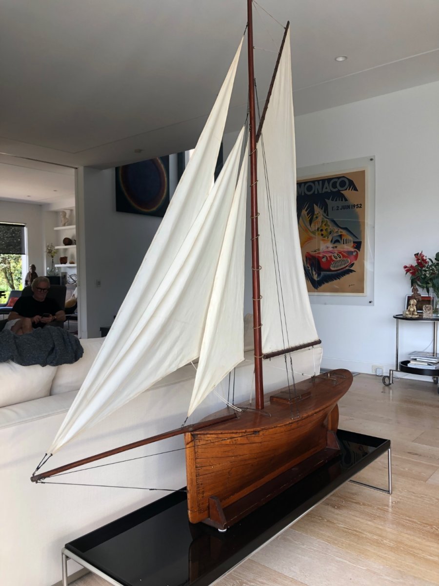
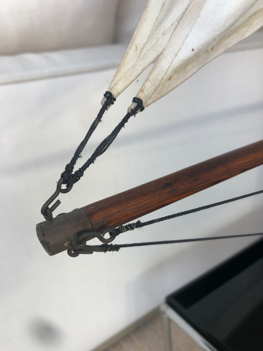
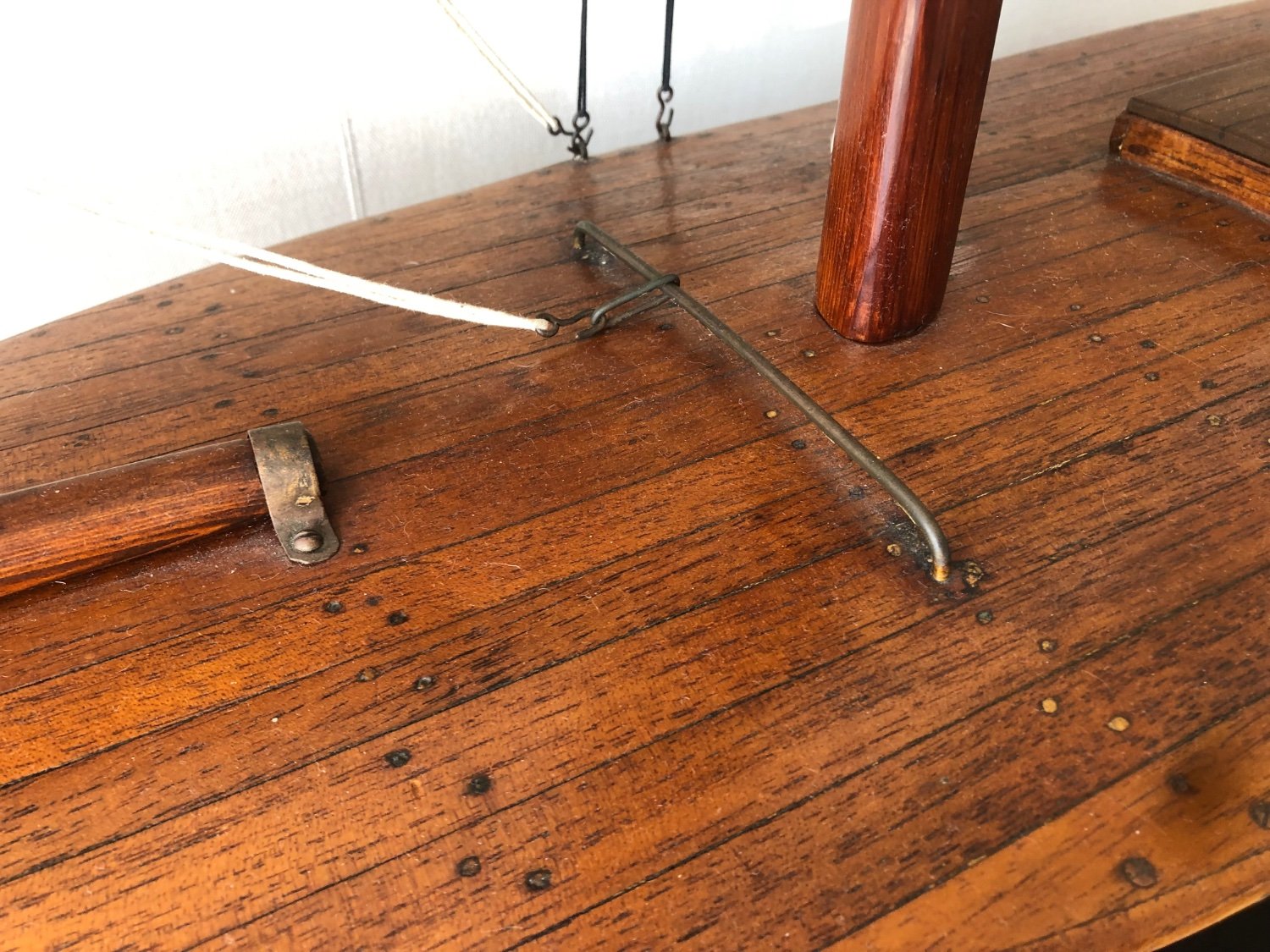
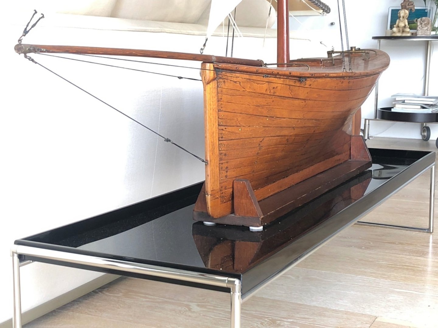
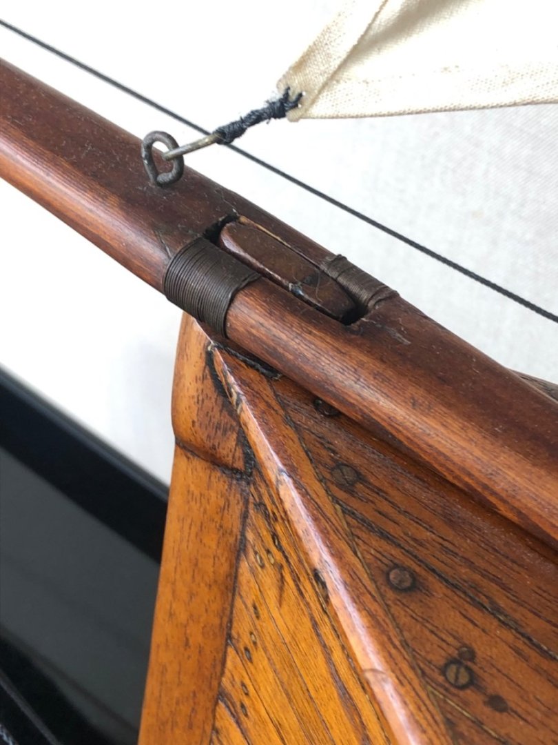
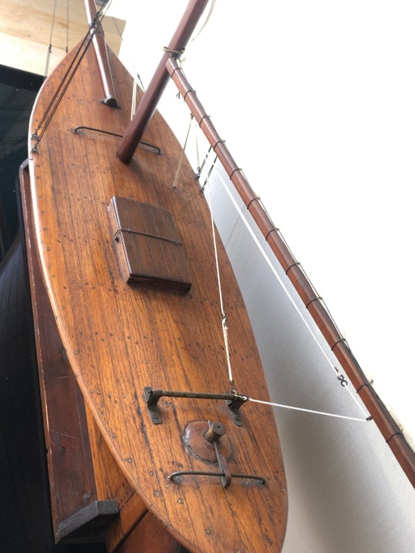
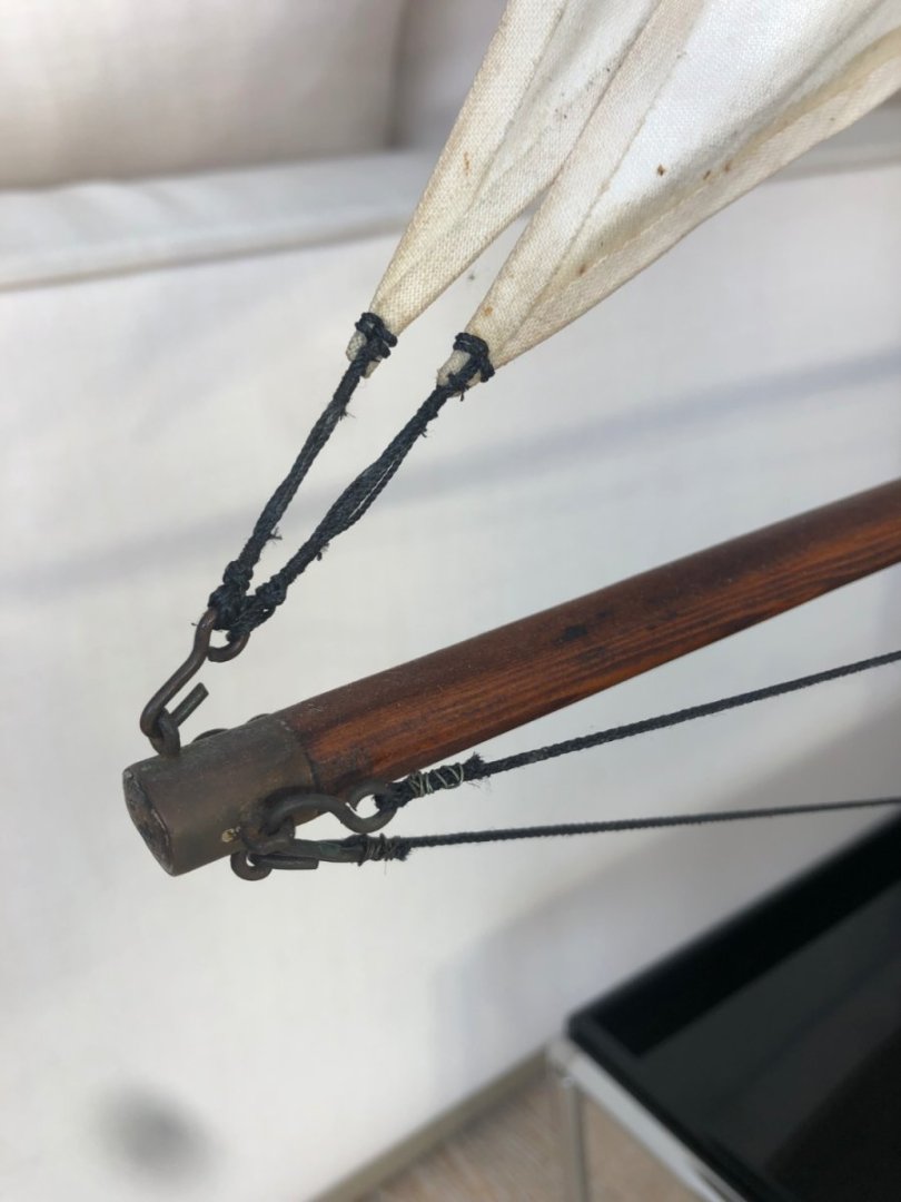
Hi Scott Thanks, some of those strings would have been perfect. I did end up getting just the thing via the internet, 2nd time lucky.....see below, the New #1 was the first (& unsuccessful) string order, & the Final was deemed good enough. I see that this is your first post, are you interested in or working on any model yachts? Posting this, I realised that I never really finished this blog off, so I'll add finished photos below & give a short overview of the completed model repair. Overall photos, in the house of the owners. The model is large, as you can see here. And a gorgeous hull shape. I am guessing it's 1880-1910 in age, probably pre-1900, as the hull shape is typical of the 'lead-mine' hulls of the 19C. Bowsprit repair at the stem. I re-wrapped the bowsprit with brass wire, where it had been done to cover/strengthen a previous repair. Sail repairs, the cotton was weak, so I painted the tacks, leeches & heads with diluted PVA, then new stitched rigging using whipping twine. In this photo, I extended further down the sail in white so it's not so obvious, but adds some badly needed strength. Tip of the bowsprit, some of the hooks were missing & were copied. The repairs did not try to o'improve' on previous work that wasn't perfect, I made the decision to leave the model with it's quirks & eccentricities (below the whipping in wire...) Foredeck, also showing how the headsail sheets were lead. This model would not have been raced, I'm sure of that. Swapping the sheets for th opposite tack would have been slow. She was owned & sailed for the pleasure. As a final note, I believe she was built in Tasmania, as the bowsprit, I believe, was King Billy Pine. For those that know the timber, it's a lovely light-weight timber with an even grain. The hull & deck is Australian Red Cedar, which was shipped to Tassie, & I am guessing that King Billy Pine was much less available in other states than RC was available elsewhere. thanks,


-
Hi Steven, I enjoy the way your models come together. It might seem haphazard to you, but it seems thoughtful to us. And the mosaic in your last post is a very fine work of art, did the mosaics as art works inspire the interest in these boats?
-
Very nice. They seemed to often (or perhaps sometimes) paint the top part of the mast. I'm not sure why.
-
That's an interesting looking magnifier, is that a drop-down second lens?
-
More beautiful work, & it's a satisfyingly large model. It has the feel of a real boat at this size.
-
Expanded polystyrene is an underrated material aesthetically, however I was wondering if you were going to do a stand, & what sort of design?
-
Hi Brinkman From a practical boat building point of view, if floors are fixed to the hull there should be some side gap, even if small. I haven't looked it up, but my guess timber will expand across the grain around 2% - so 3mm for a 150mm board. Floors can also be fixed into panels that are loose, not fixed to the hull - in that scenario they could be done without gaps. For a working boat, there's a lot of advantages to loose floors. Is there evidence in the example you cited, that the floors were fixed to the hull? PS The dark colour is beautiful
-
Congratulations Vaddoc, A gorgeous model & one that must have been a very demanding build. You really had to build the whole boat & it's a beautiful result.
-
And a very nice piece of metalwork too, a very believable look of wrought iron - could you tell us a bit about how you made it? It doesn't look like brass, but perhaps it is... In terms of the vessel, what was the bowsprit used for?
-
That's what we used for the kayak, it came with the kit (kayak was a Chesapeake Light Craft LT17). It went well. Do you use this on any models or just on your lovely small boat?
-
Hi John, Steve Thanks for the offer Steve, I have used quite a lot of epoxy. I built a small open gaff sailing boat some years ago (strip planked), helped my wife build a lovely plywood kayak, & myriad repairs on our boat Cherub. I'm using Araldite Super Strength for the model. Per ml it's expensive, but the tubes make it easy to proportion a serving, & the quantities will be small. Also, it is far tougher than it used to be. I have tried West System, Bote Cote, Norglass, Epiglue, Aradite & the SS Aradite is almost the equal of Epiglue. The 5-minute is good for some uses, but that doesn't include planking this model. For a model, I would only consider an epoxy that was pre-mixed with fibres, that is a 1:1 ratio, & available in a convenient form in small quantities - other ratios wouldn't be practical for the quantities we typically mix. So that cuts out most of the above, & I'm not a fan of Norglass epoxy. Lastly, it is widely available. Previous models I mainly used PVA, especially Titebond. Do you use epoxy for models?