Mark Pearse
-
Posts
840 -
Joined
-
Last visited
Content Type
Profiles
Forums
Gallery
Events
Everything posted by Mark Pearse
-
 thanks Jack, that's very interesting. It's hard to imagine, but does the tiller kick a lot? A metal tiller with the unforgiving nature of ice... Also, it's fascinating to see that the sail shapes are so similar to the boats of the same period & yet the demands would be more different than it seemed at first glance - at the incredible speeds they go the apparent wind is almost always going to be well forward & strong to very strong, maybe even 50 or 60+ knots apparent. You'd not get that very often on the water & yet the sails & spars look like you could just drop them straight into a boat....They must be a blast to sail on.
 -
Hi Jack I had to resolder some joints that had broken in a difficult position & managed to control the excess heat by using small pieces of wet rag wrapped around the bits I wanted to protect, & put the solid head on the flame torch. On the unusual main sheet system, I have some thoughts on why it's set up that way. It's effectively a double ended main sheet, so that the boom adjustment has either speed of adjustment or power. If you want to pull the boom in quickly & there's not much load you use the aft sheet, then when the wind load comes on you would use the forward tackle at 6:1 or whatever it is. You'd have to keep an eye on where the sliding block sat & not let it get too far forward or back, maybe there's a way of locking off the boom & resetting the position of the sliding block during a long leg. A question: on the actual ice yacht, what are the skids made from? thanks, Mark
-
Yes the deck would be a problem for pivoting - for lifting, if the mast was very heavy you could use a simple lever system below decks, & as it gets lifted - say each lever lifts the mast 20cm - you chock the mast to stop it falling back (or use ropes from above taking up the slack as it's lifted, the ropes going through the deck hole & tied off to some fixed strong point) & do it again. When the mast base clears the deck level you use the ropes to restrain it & do a controlled slide along the deck. It's starting to sound possible, but maybe that's too much optimistic imagination... BTW, I have a small amount of mast lifting experience, one solid timber one on a 17' boat & it was manageable by myself but quite difficult - a mere toothpick compared to your vessel. We also lifted a a 9.5m timber mast with an electric crane, it was hollow - a wall thickness of 1" & a diameter of 140mm - so probably only 50% of volume solid timber, so quite light for the size & much much slimmer than your Dromon mast would likely have been. I reckon it would be possible to lift one of these by hand - but only with some sort of mechanical advantage.
-
HI Vaddoc ....if the solder & aluminium doesn't work out, I wonder if there's a way of colouring epoxy to a silver or grey & glueing the aluminium?
-
I believe the mast step arrangement of a simple slot would easily be enough to hold the foot of a mast, provided the top of the mast is stayed. You mentioned that you doubted that the masts could be raised & lowered at sea - but I think it's possible in these craft (not because I know anything about the boats, I must add). To hold the base of a mast in place doesn't need to be complex, & I think that raising & lowering is possible because the boats are so long compared to the mast height. I would guess that they would pivot the masts (not lift) because it would be easier, & rigging lines to do that job would be simpler than what would be required to lift the masts up. In terms of the mast step, if the rectangular slot was long enough so the end of the mast could rotate as the mast swings, then there would be no impediment to it rotating - but it might not be stable enough. Possibly they had timber blocks that sat in the slot either or both sides of the mast, wedged to hold it all tight. If you want to lower the mast you'd knock the wedges & blocks out & the mast step would then it can rotate in the slot. I would hazard a guess that when lowering there would be a point at which the base of the mast came out of the slot, at which point you'd need a heavy rope controlling the base of the mast because there would be a lot of load pushing it. You'd need to control it with that rope & maybe even allow it to move along to be shipped where you wanted it in the hull.
-
Hi Steven - Just following the discussion with Pat, was it certain that the masts sat in raked holes? NB: I don't know anything about these craft.... Mark
-
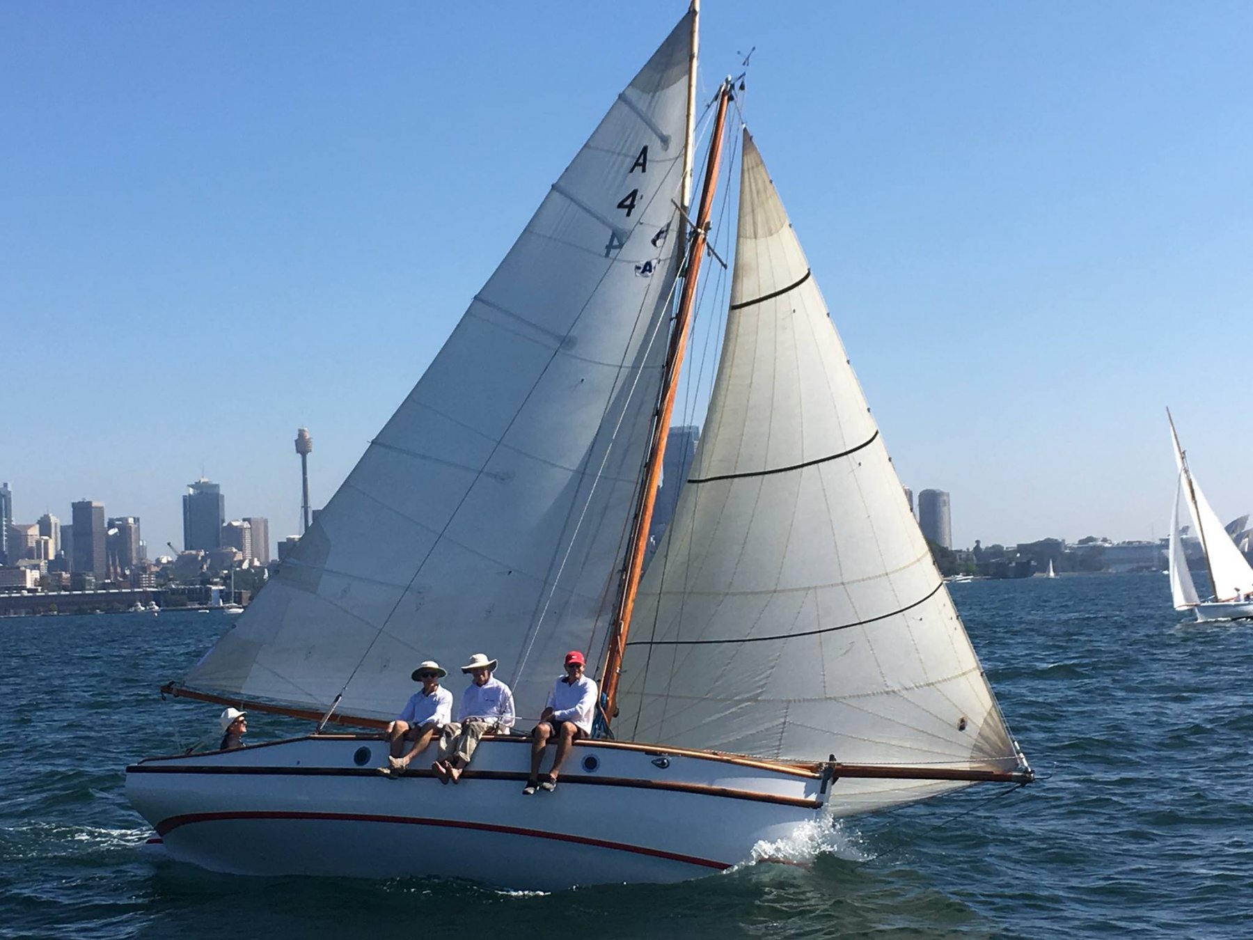
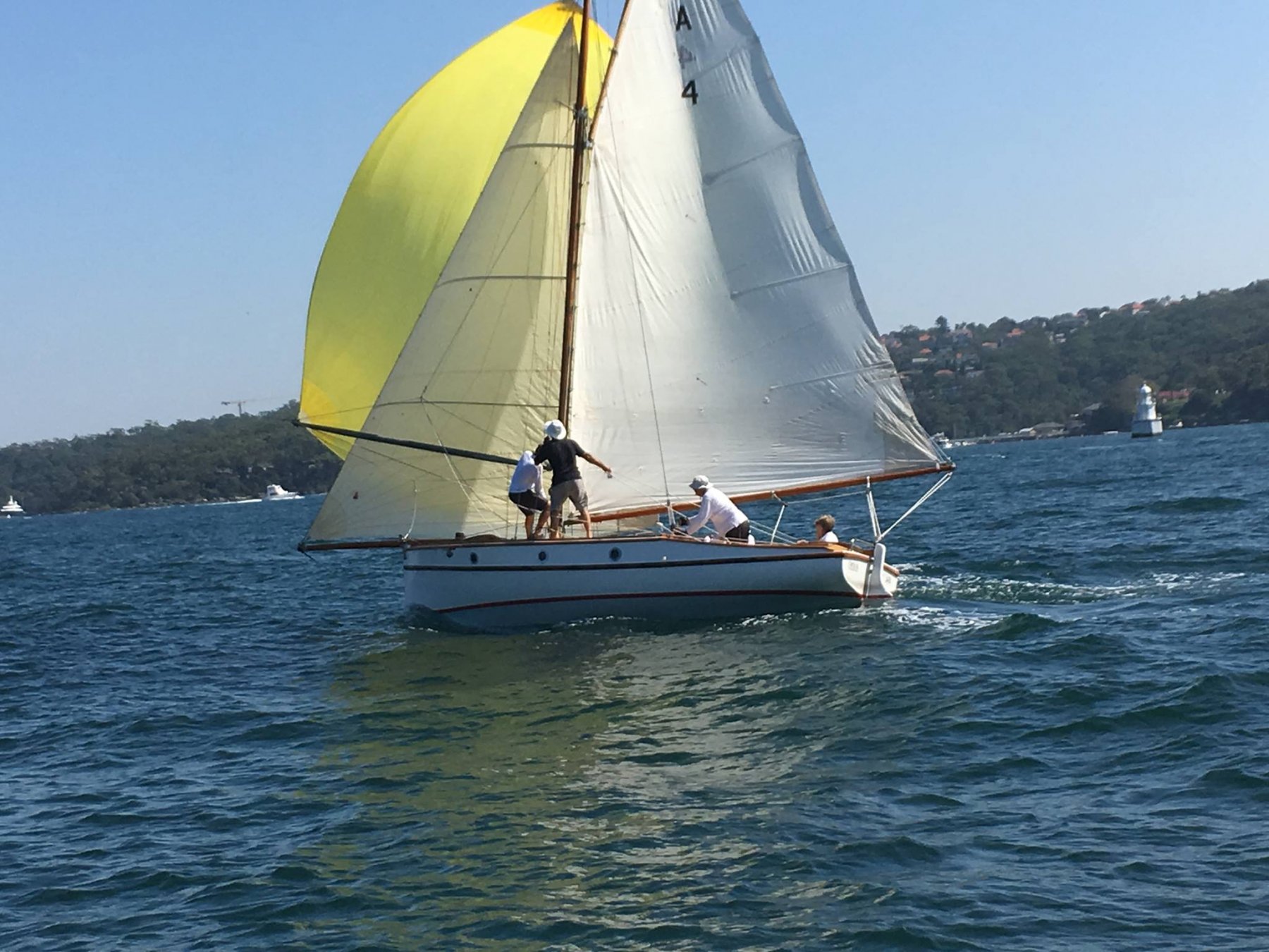
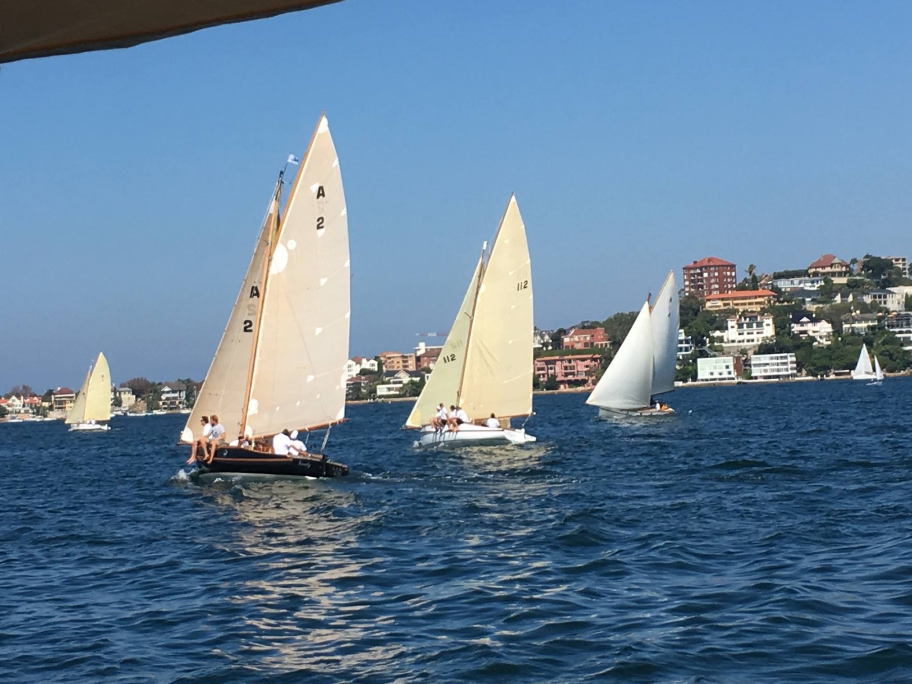
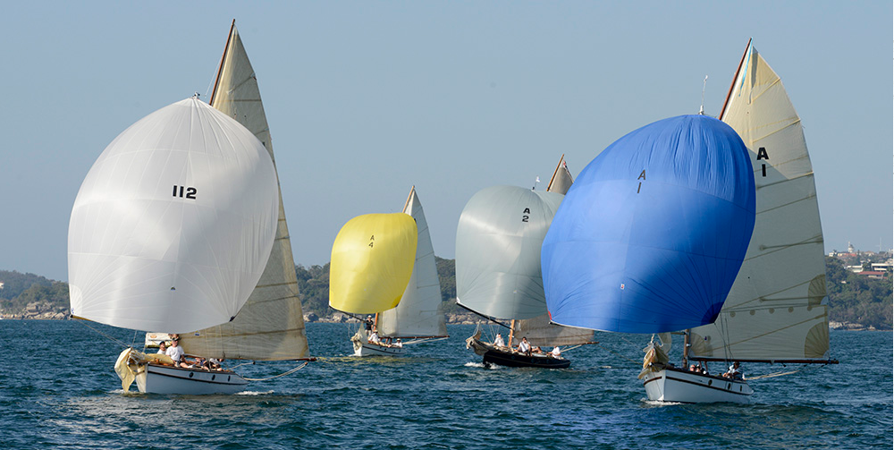
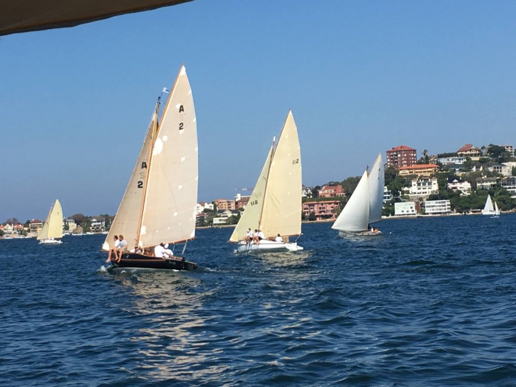
Hi Bedford, good to hear from you. Yes we saw the Waratah over towards Kirribilli & I remember hearing the steam whistle. You're right, we were racing - there's two annual races Rangers vs Couta Boats. Very light conditions but great racing. Some photos below - our boat is A4. Mark


-
Hi Dick a beautiful model indeed, & the journey through history was fascinating. Now I can see that the drawings & paintings you posted examples of are quite accurate. Mark
-
Hi Jack fascinating. The link you put in early in the posts was amazing, it's one thing to know they are fast & another to see it (even on screen). I'm guessing they were just too fast for a spinnaker? There's a wire, or maybe a shroud, that looks like it goes full length below the main fore/aft frame - what does that do? Mark
-
Masts usually go through a deck or cabin roof, a king plank does a lot of work but it wouldn't take any of the downwards mast loads. The mast goes down to the keel & usually sits on a mast step there (basically a beam that spreads the mast loads), the last would likely just go through the cabin roof & deck & maybe/maybe not be wedged against them; the mast can be free to move around a bit within a gap of about 1". I'm not sure what the detail is in the UK to waterproof this joint, but traditionally it would probably have been some sort of canvas boot, tied off to the mast & also tied off over a raised edge around the cabin top/deck hole. Even for a model, I would make sure you support the mast load down to the keel whether or not the mast goes through the cabin, timber can slowly bend over time from ongoing loads, & maybe even put in a mast step the equivalent of about 1-1.5m long. I wouldn't think 3 shrouds would be necessary, it's not a large yacht, & if you do gaff rig they are lower stress than bermudian...but you would need running backstays as well as the two each side on the mast - a cap shroud & a lower each side. On the rig, I believe that a gaff cutter would be a good choice (an internet search showed that they were done in this rig), because the boat is probably heavy & it's a more powerful rig than the triangular Bermudian mainsail. A cutter rig because that rig is very popular in the UK & this is definitely a classic English design. Lastly, the gaff rig just looks so damn good....but this is just the opinion of an idle bystander. On the transom, it was also popular to put the boat name on a wooden plate (or two). If your model has a double name then it might work to use plates & cover the drill damage that way...just a thought. I hope this assists, & the ultimate decision should be yours
-
the deck looks very good Vaddoc, were you thinking of doing the transom clear finished? I did an internet search to see what the rig is, & there seems to be a number of alternatives....what are you thinking? Mark
-
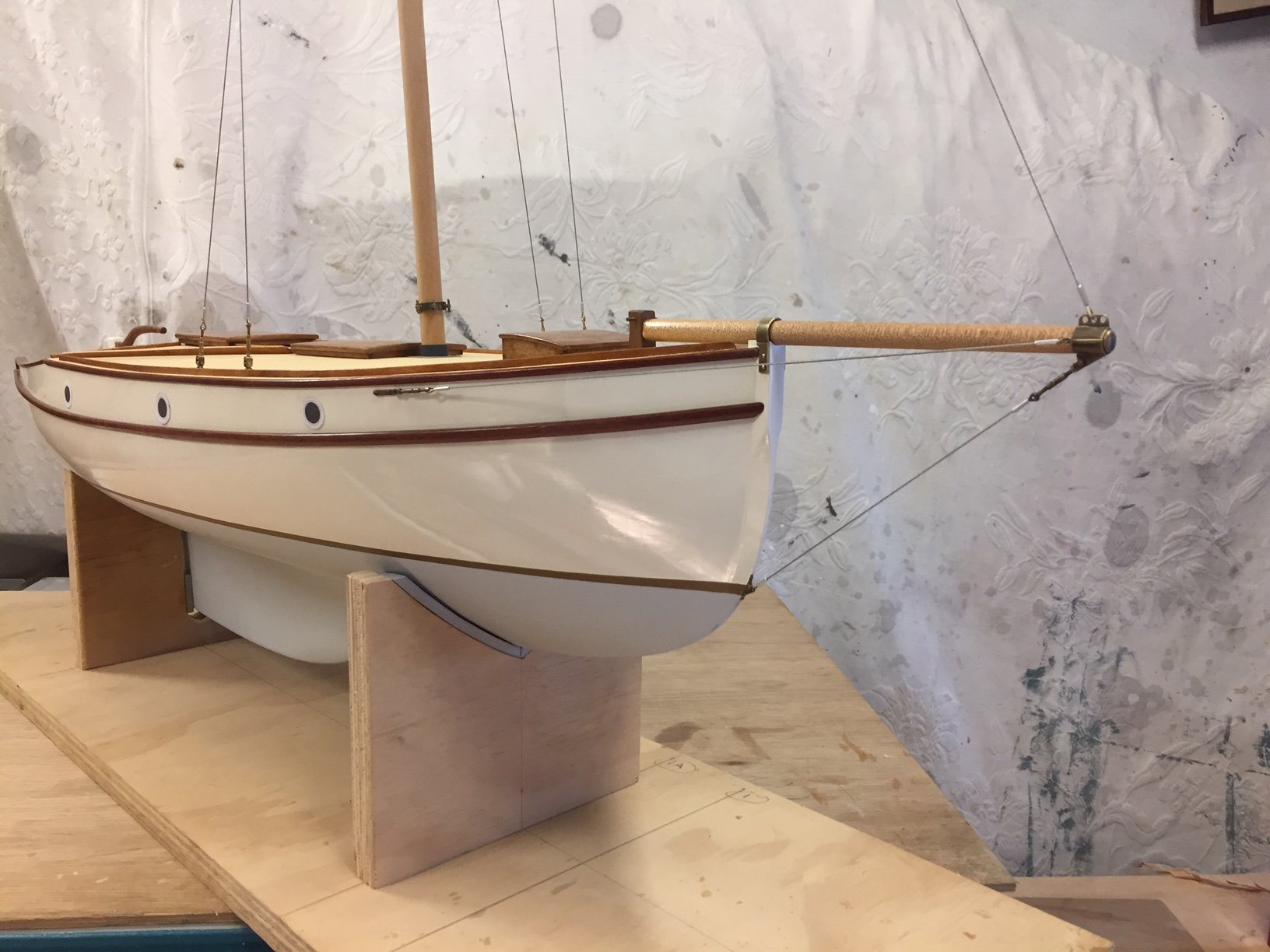
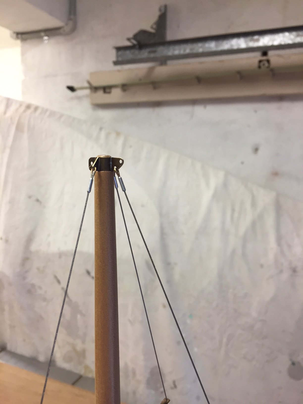
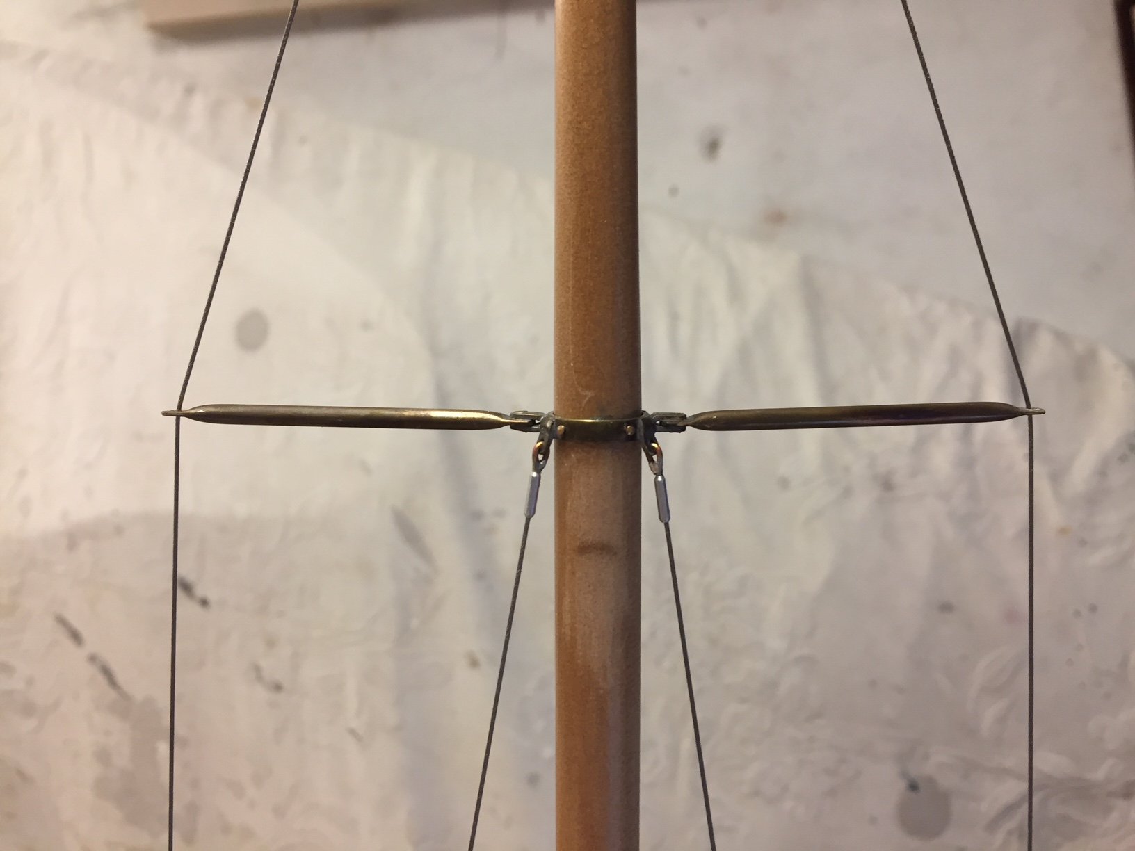
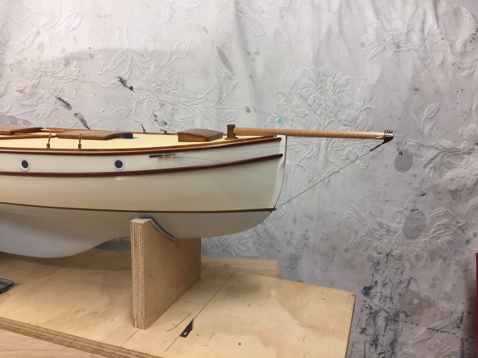
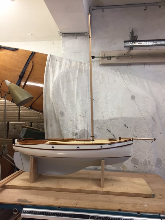
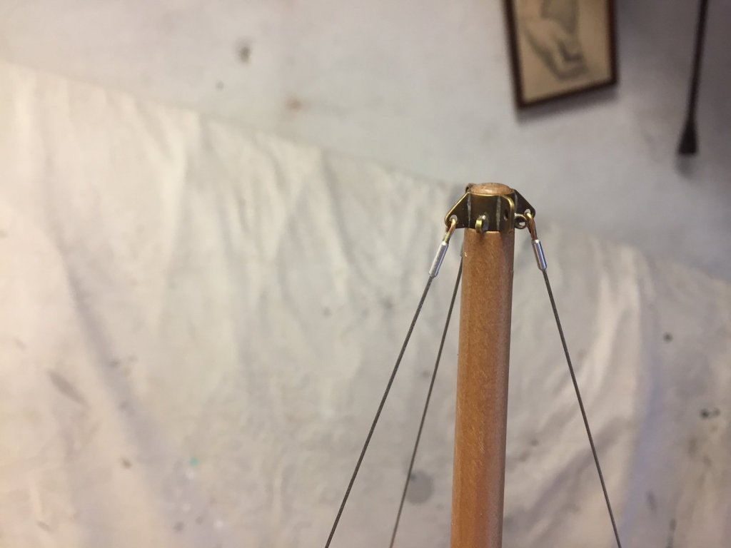
The main parts of the standing rigging are done; and the gammon iron is done & installed. The gammon iron is probably not accurate to reality, it has no bow rollers for anchoring etc. This is the point at which I want to separate the point of this model from doing a fully accurate model of a yacht. I won't be doing fairleads, bow rollers etc, the important part of this model is to realistically show the last yacht design by Cliff Gale, and some of the minor details will not be necessary. Partly this is because the details on a model seem to be more visible than on a real yacht, so in a way not doing them is trying to keep the focus on what I think are the most important parts - hull shape in particular. So, the mast bowsprit & standing rigging: Some of the rigging details, shrouds chain plate connections: Gammon iron: Mast cap from bow starboard side Mast cap seen from the stern side. The small rings will take the running backstays & the empty cleat is for the peak halyard. The spreaders:


- 411 replies
-
- 15
-

-
Hi Russ I have found the Tamiya masking tape for model making use to be superb.
- 420 replies
-
- 4
-
-
- captain roy
- lugger
- (and 2 more)
-
beautiful sails indeed, the tiny lacing & reefing eyelets are amazing
-
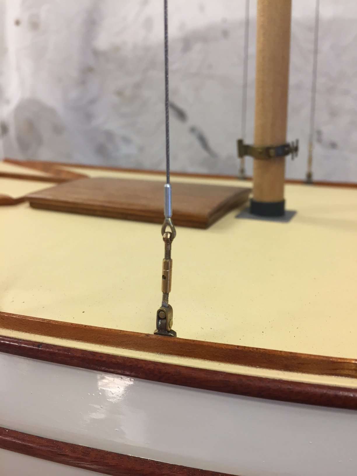
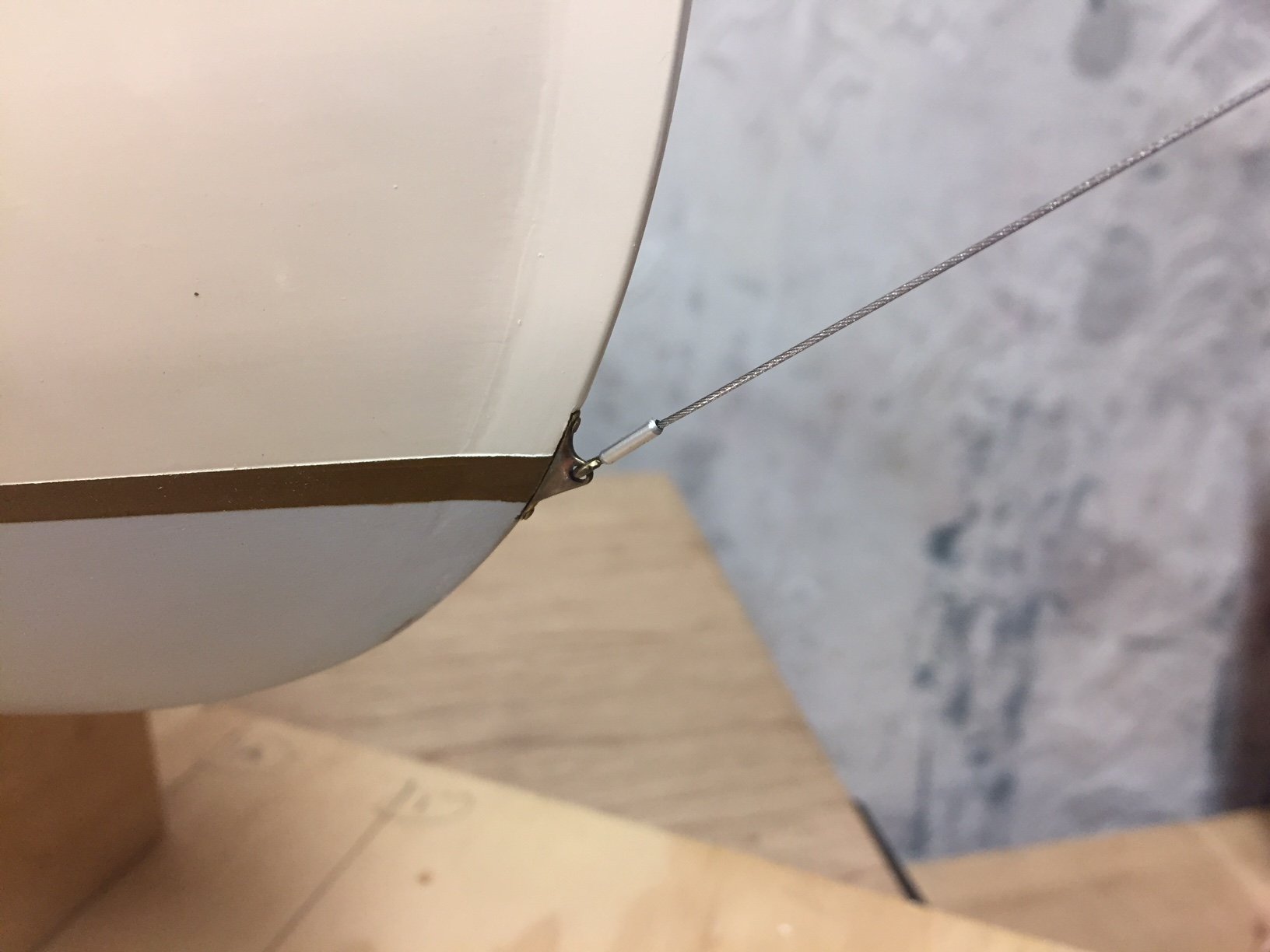
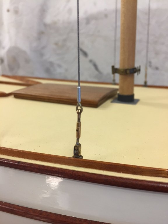
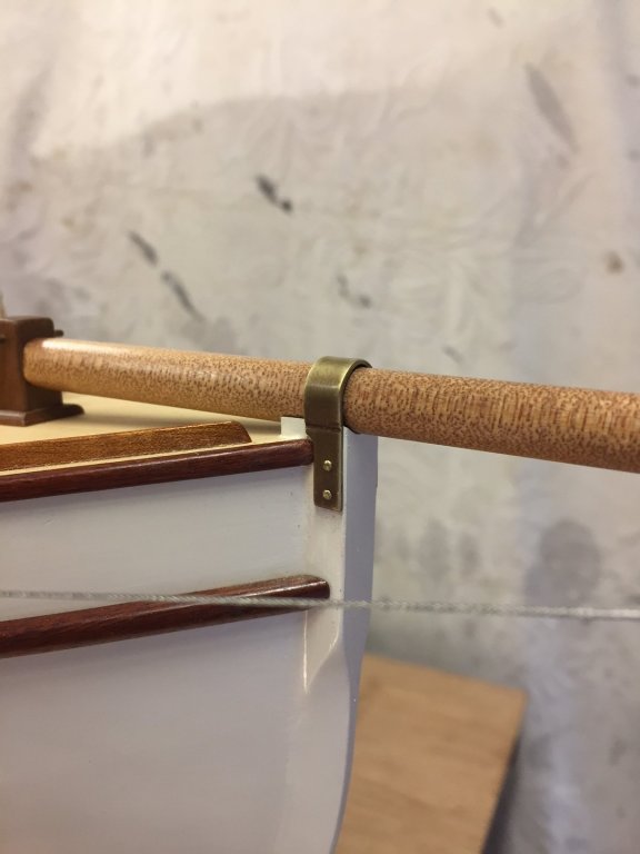
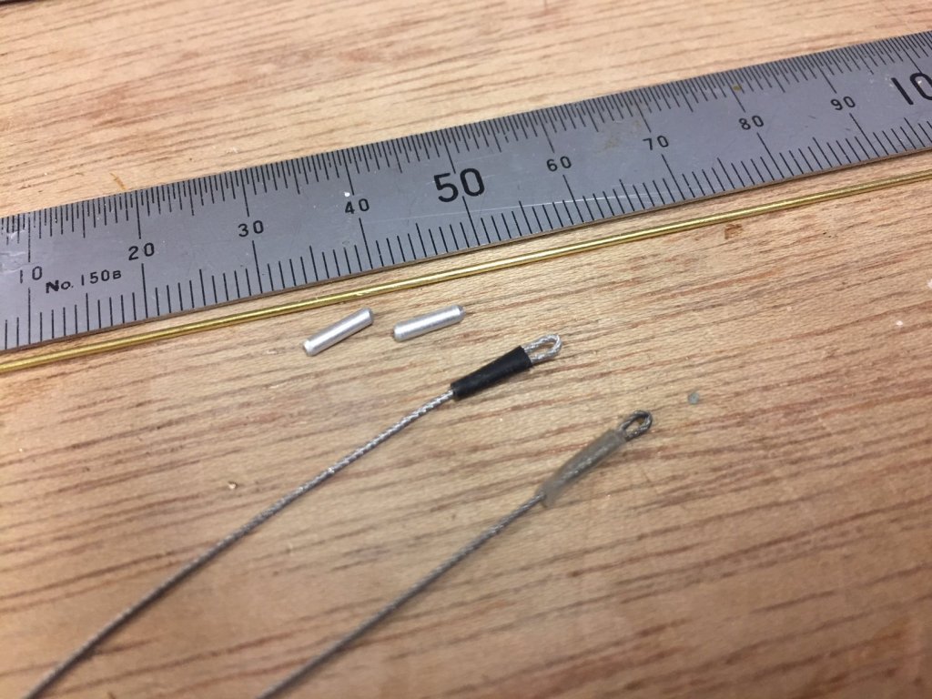
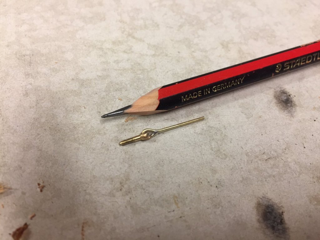
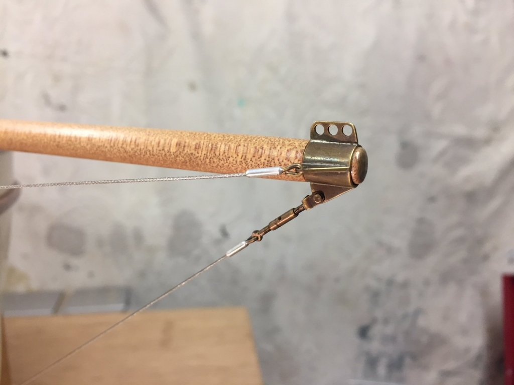
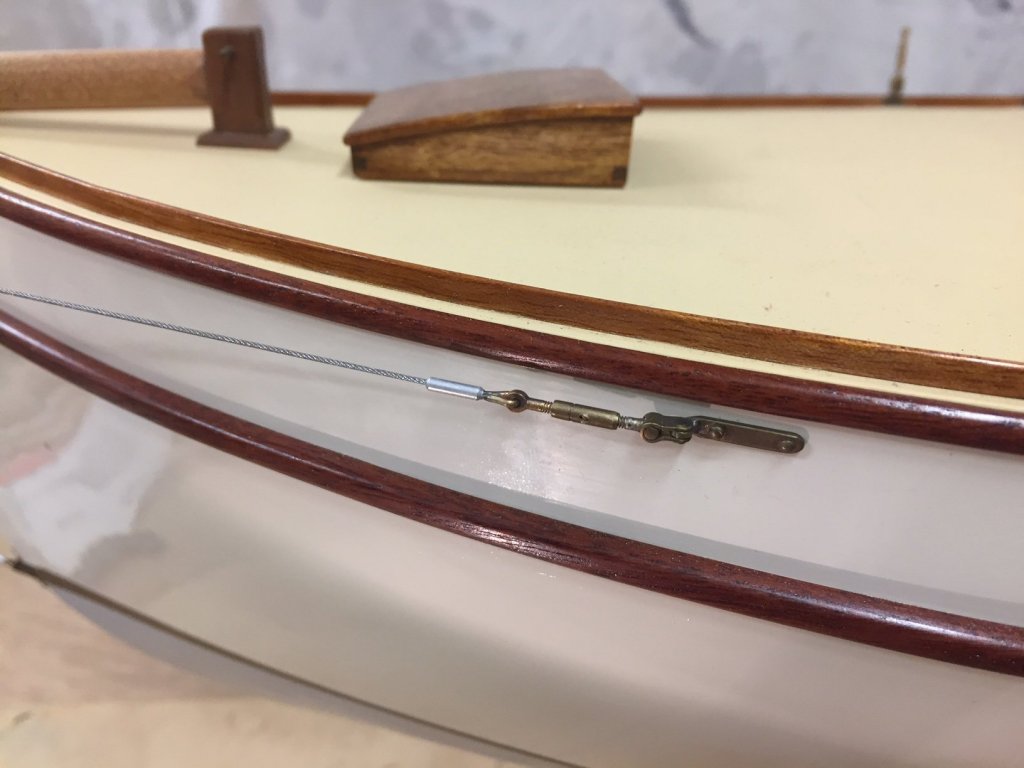
I've been paying around with alternative swages for the rigging wire. They aren't really needed for the model, but actual rigging would have them, & they - at a model level - join the wire (jewellery SS braid, nylon coated, thank you brains trust) to the chain plates or turnbuckles. There would be other ways of doing it but I wanted something neat & not fussy. I experimented with heat-shrink tubing, but it looked too old fashioned for this yacht; & settled on using some aluminium tube & brass rod. The tube replicates a swaged joint & the rod tries v hard to look like a neat eye joint. You can see below the parts (ends of swages are chamfered) & the heat-shrink results, which don't look mechanical enough. Glue is CA. Brass rod into a eyelet, the other end of the rod gets glued into the aluminium tube. The cranse iron : Bobstay chainplate: Whisker stay chainplate: The overall. I'm especially pleased with this photo, the rigging joints should not jump out at you, so I think it's more or less in scale visually. thank you


- 411 replies
-
- 15
-
-
Yes, that's the process I used. Tamiya masking tape from a hobby shop (recommended, great quality), being careful to burnish the edges of the making tape down, especially for the final waterline (boot top line). I didn't thin the waterline paint, so that it was thicker & would hopefully bleed under the tape less. There were some bleeds & I scraped them off with the tip of a knife blade when it was all dry. On the topsides paint, I did multiple thin coats of paint - maybe 4 coats - not worrying about whether is was opaque or not. Sanded between using 000 steel wool, or v fine paper.
-
Hi Vaddoc I used both acrylic & enamel for my hull, but I've only done it the once to a model so that's not much experience. I got some brushing thinners for both & didn't have any wet edge issues. I used gloss enamel for topsides & matt acrylic for the antifouling paint. Happy with both, but was very impressed with the acrylic - but I'm not sure though how good their gloss level is. The only surprise I found was that the Humbrol enamel really needed to be mixed for 5 minutes or it took days to dry. My experience with painting the model & also full size hulls is that you are best to brush lengthwise along the hull, & try to brush towards the wet paint rather than both directions, although it might not be possible to do that 100%. good luck with it...
-
Hi Vaddoc that looks great - I would think the deck will be enough to brace it, but bulkheads would be even better. Hi Druxey, I hadn't realised shellac was nasty stuff. Could you explain this, thanks. Mark
-
sensational Keith, well done & thank you for showing us, it's been inspiring to see all the best, Mark
-
good question. Mitbok, what is the peak halyard to gaff rigging? A large but low aspect rig, very interesting. She will be a beautiful display model. Mark