Mark Pearse
-
Posts
840 -
Joined
-
Last visited
Content Type
Profiles
Forums
Gallery
Events
Everything posted by Mark Pearse
-
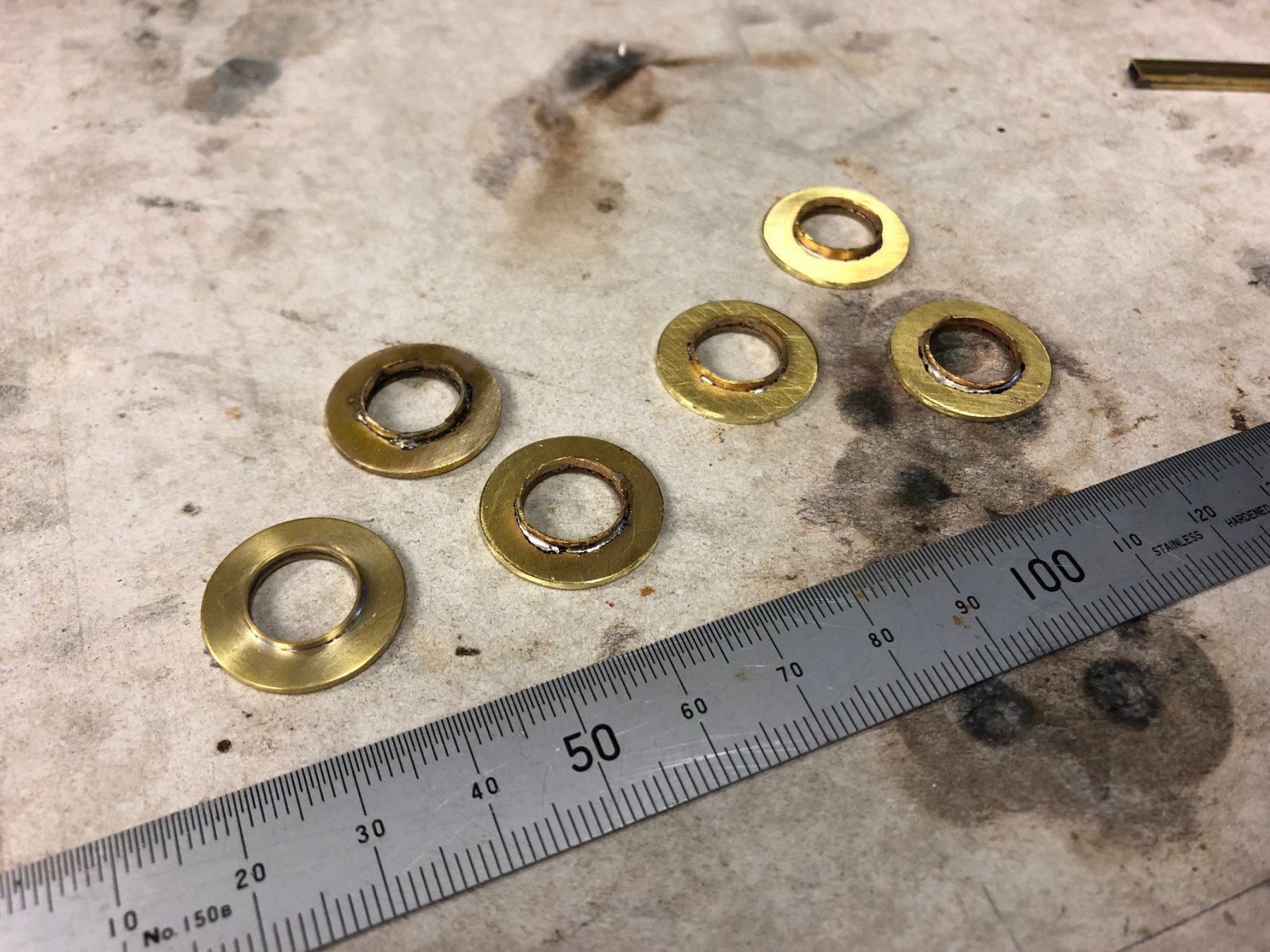
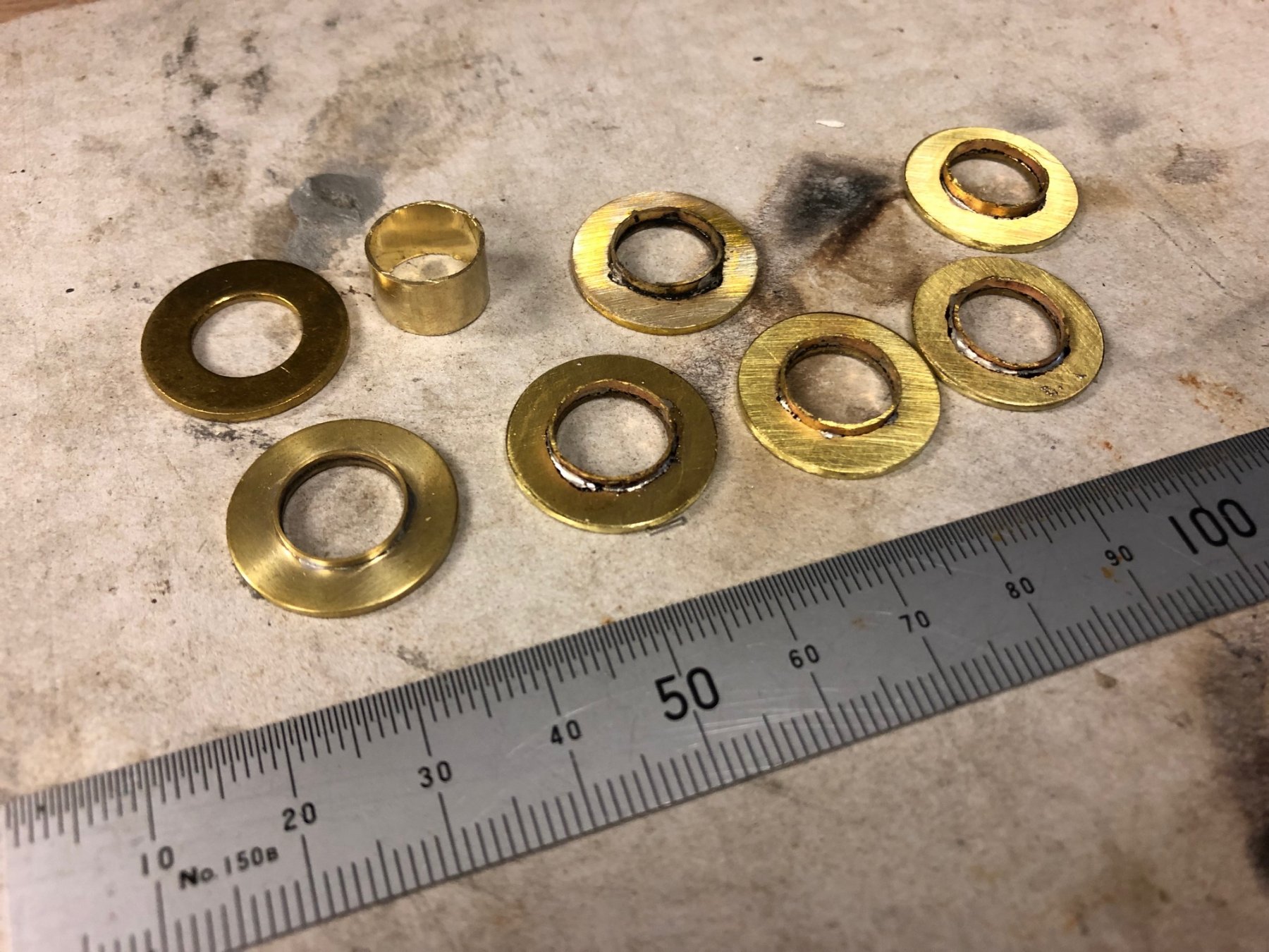
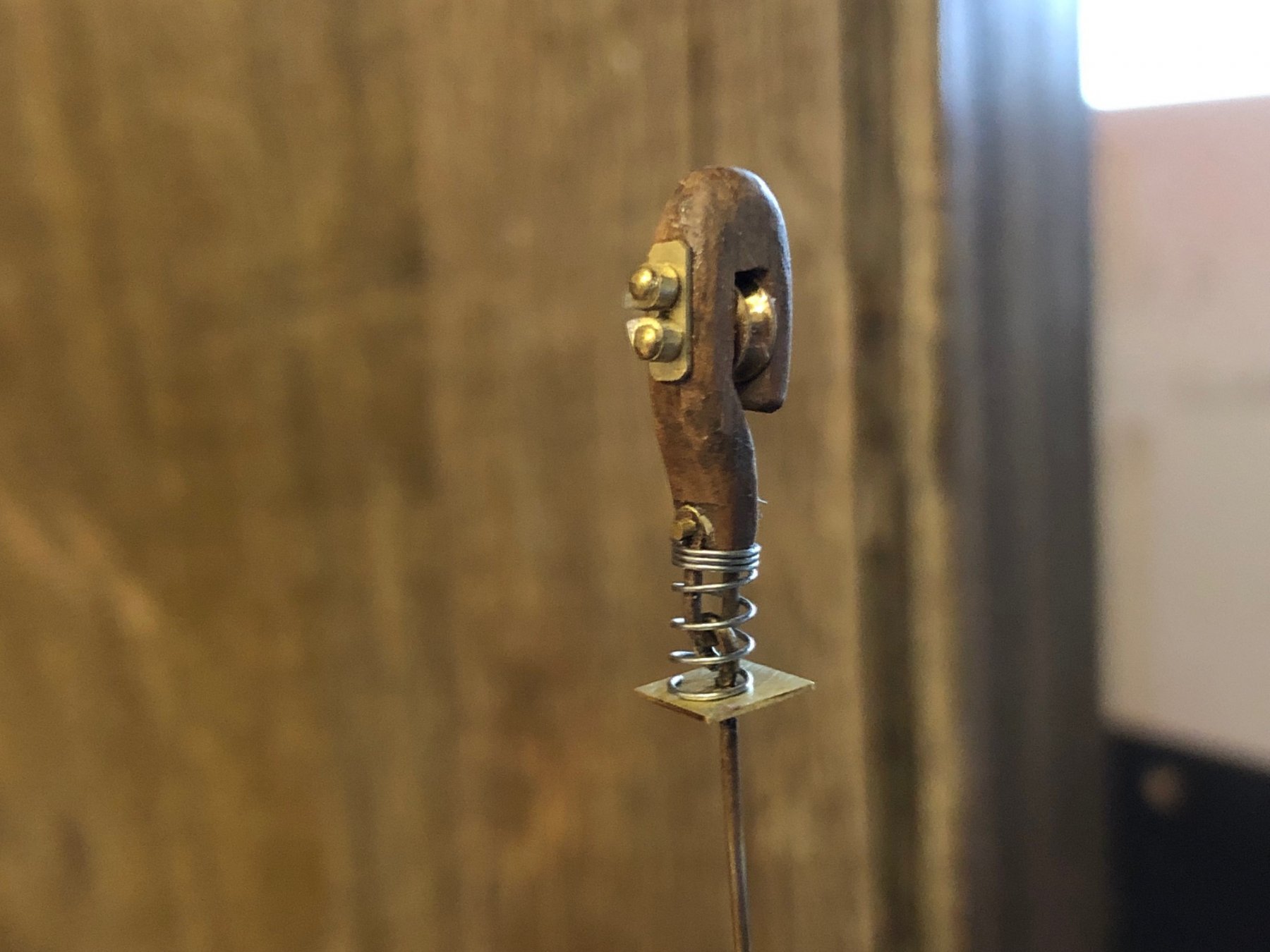
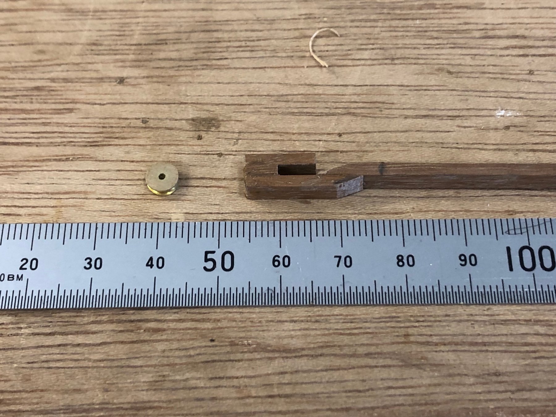
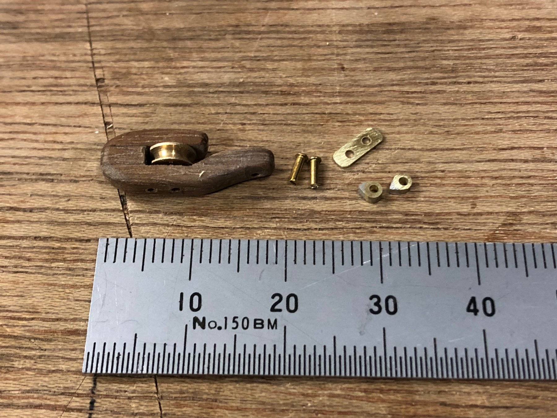
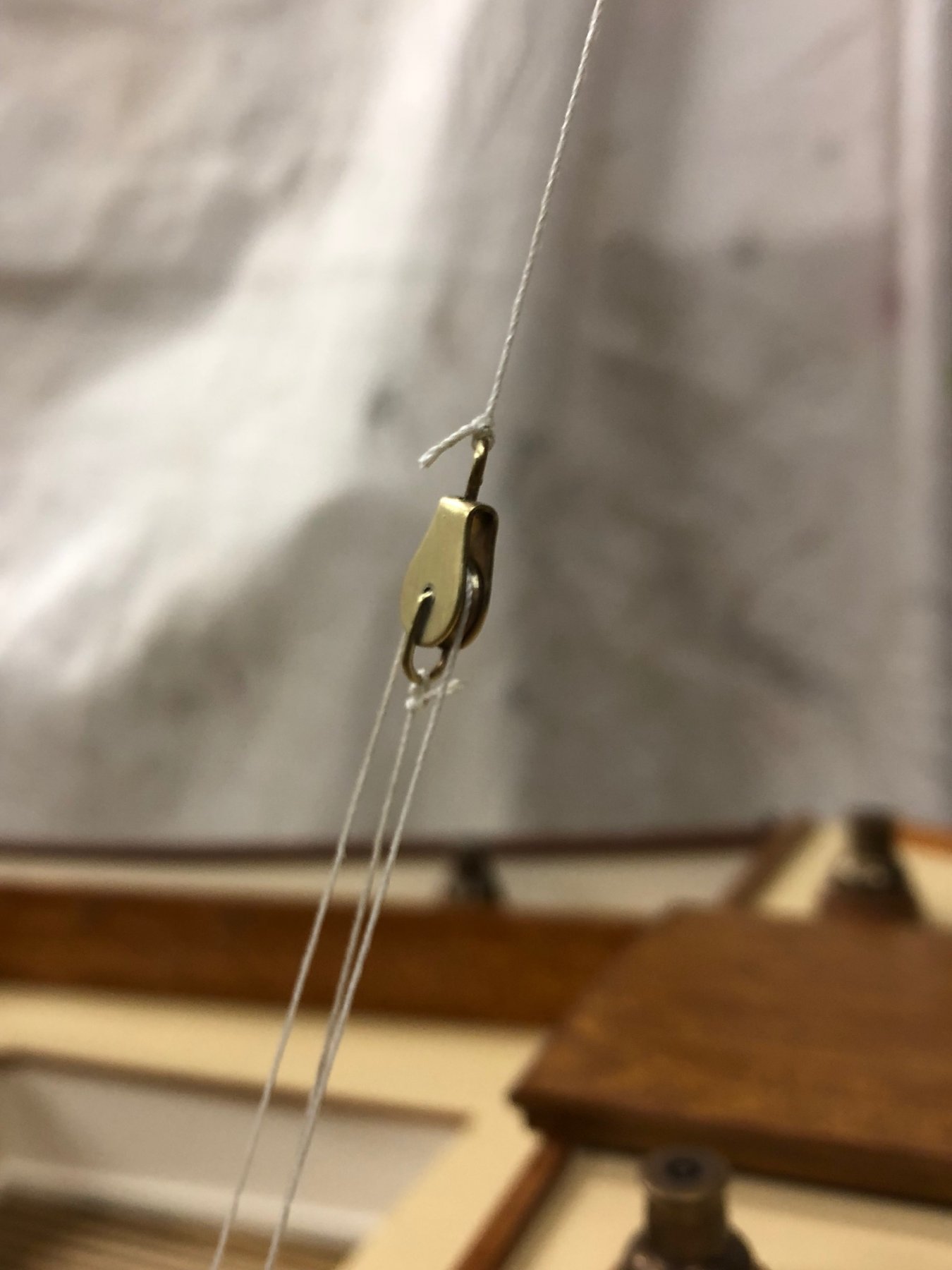
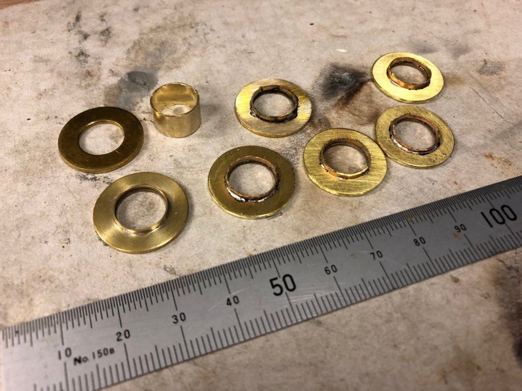
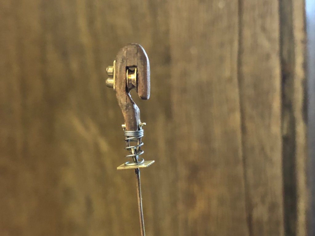
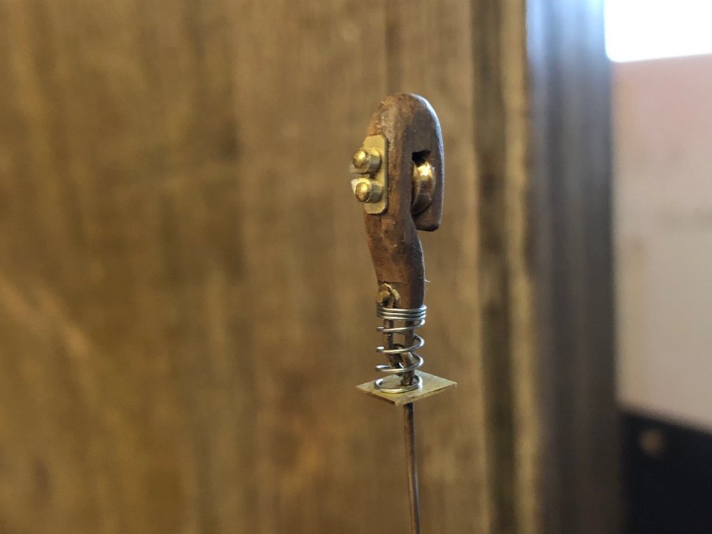
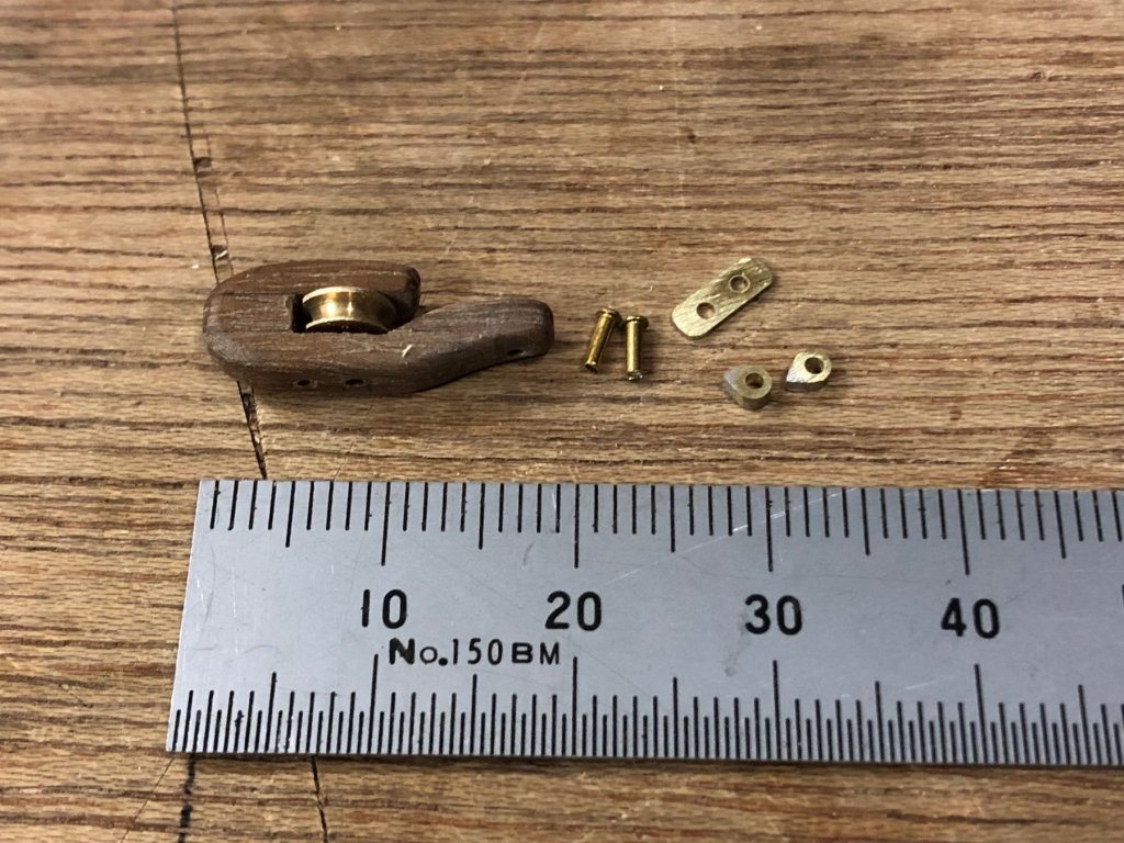
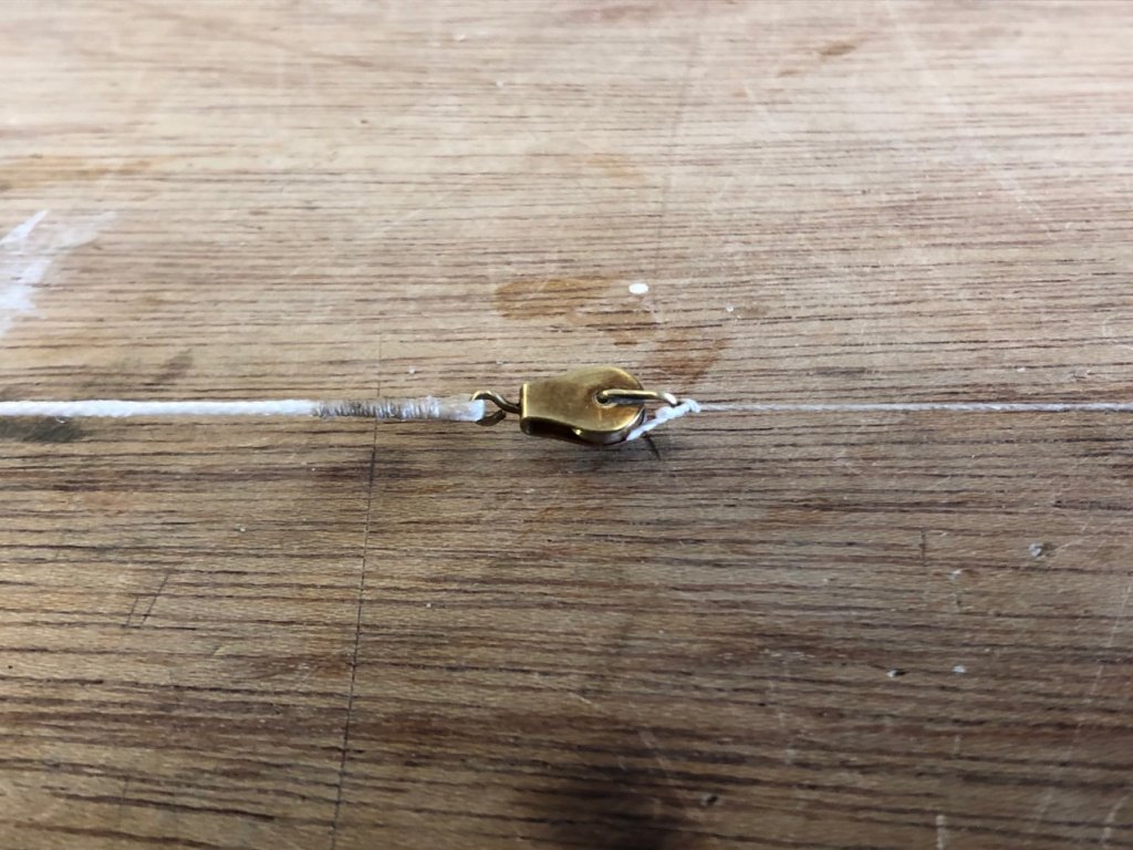
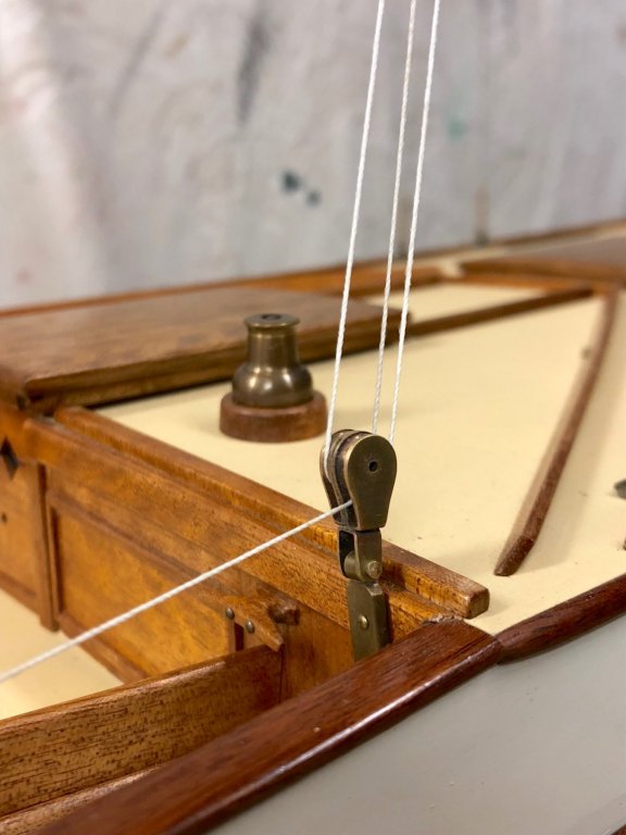
 The cockpit snatch block is now done, & waiting for the mounting block to be finished. The spring without load pushes the block on an angle but I'm expecting it to sit in line when a bit of sheet tension is there. The sheet will need to squeeze into the cam cleat, & a bit of sanding might be needed. The layers of timber are visible, but it doesn't bother me. I'm getting the portholes done as well. The earlier sample & raw materials (brass washer & tube) are one the left & the latest ones are the others. The forward ones are slightly smaller overall diameter, & I'll just reduce the size with sanding blocks. thanks
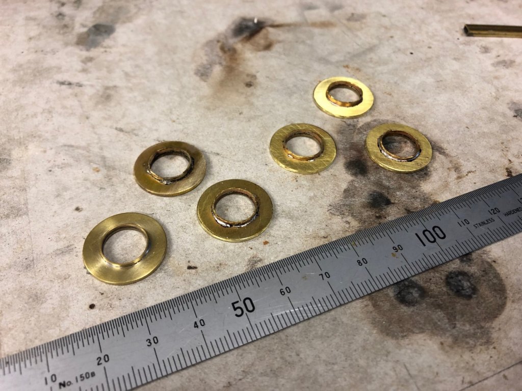
- 411 replies
-
- 11
-

-
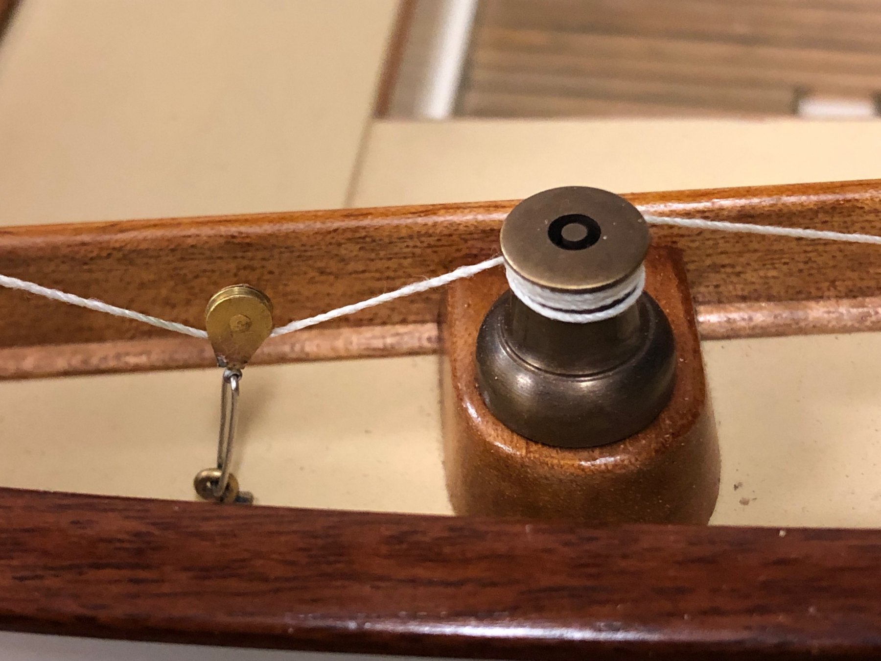
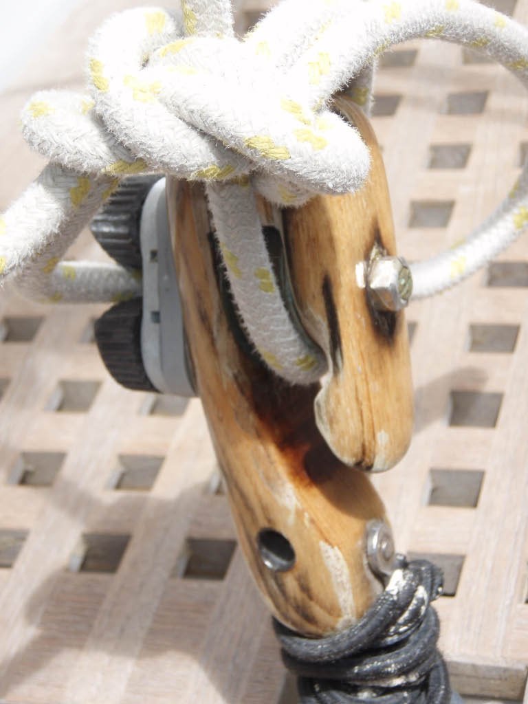
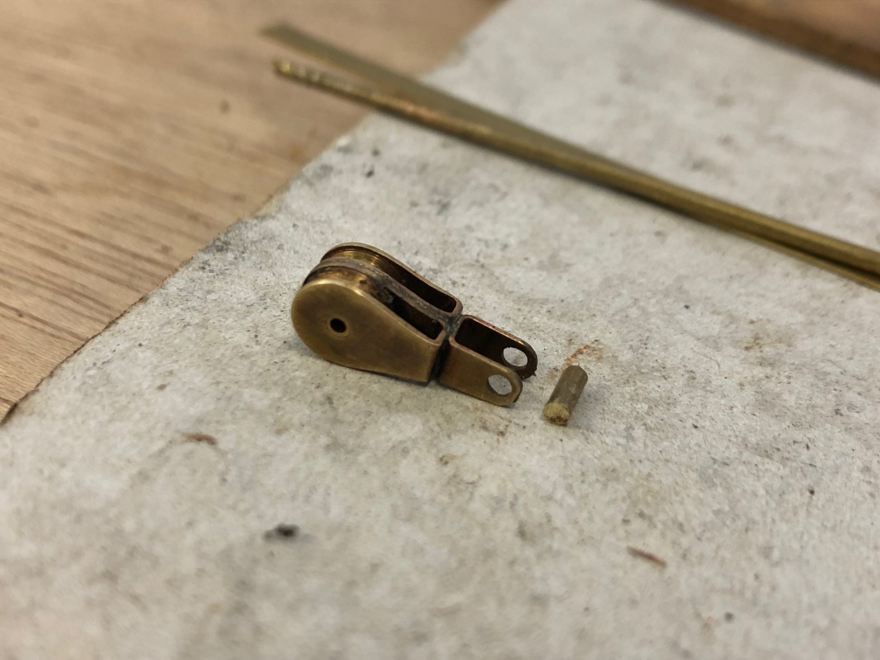
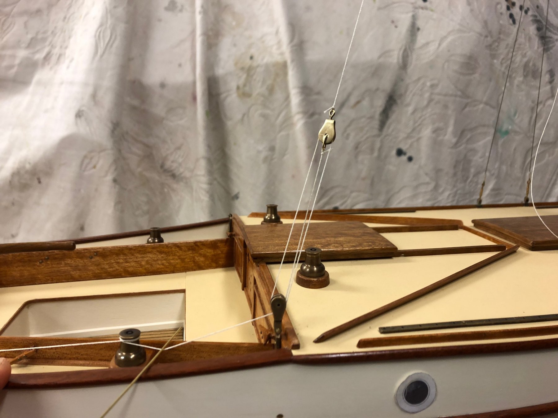
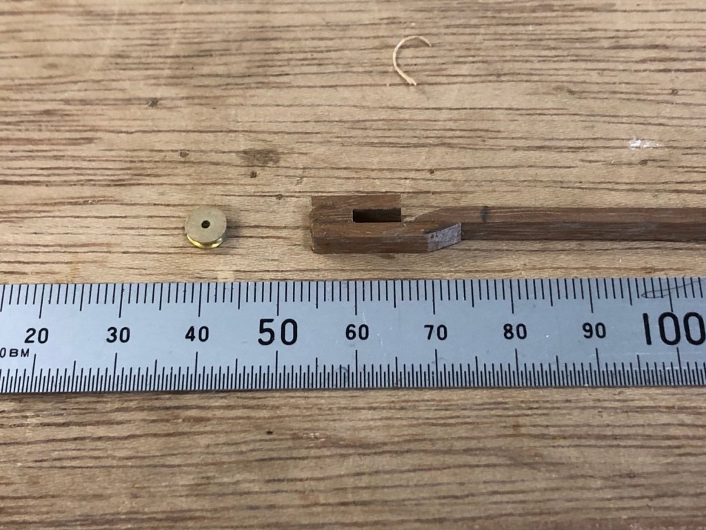
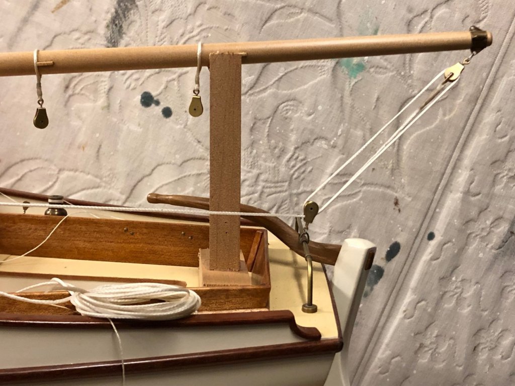
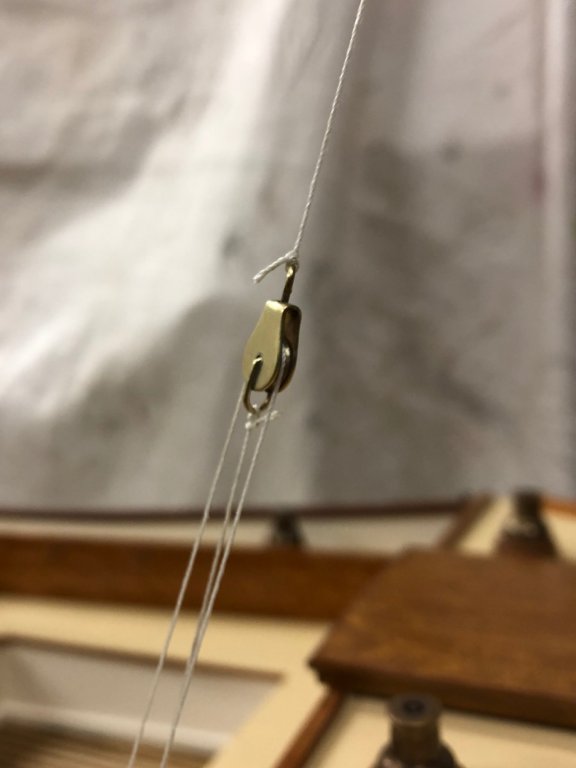
HI everyone, I've been doing some work on the model yacht, slowly moving along. The main sheet block in the cockpit sole is a snatch block, a popular detail for smaller gaffers here is the photo below - & it's not a very good shot, but the main sheet goes below the sheave & the wraps around the side of the block body & is held by a cam cleat. This is so you can quickly let out a lot of mainsheet, & it's easier to bring the main sheet on by pulling downwards (rather than upwards) & then to secure the sheet at this block as the last thing. The mess of black stuff at the bottom is a bundle of shock cord that's to make it a stand-up block. I'm sure this doesn't at first strike anyone as a good setup, but you can't bear away at all on a breezy day without easing the main, & if you need to do it quickly you have to dump a lot of it fast. I selected a strip of Spotted Gum that is the same thickness as a brass sheave, & made the ship from cut strips. Then roughly shaped. The parts for a cam cleat are there, the eccentrics on the cams were soldered blobs on a solid rod, then sanded to shape. Some more shaping on the timber required. I plan to make it a stand-up block with some spring from a plastic pen. Other minor details underway are: the small lead blocks for the running backstay tackles are installed; & the mainsheet setup is underway. The smallest blocks are tiny etched ones & the main sheet is scale braided poly rope about 1mm diameter - a bit thin but but looks right. thanks


- 411 replies
-
- 14
-
-
nice resolution of the detail Michael; & thank you for the Cornubia video link - it's interesting how flat her wake is for such a large vessel Mark
-
15' Dinghy by Bedford - FINISHED - 1:1 scale
Mark Pearse replied to Bedford's topic in Non-ship/categorised builds
beautiful. Thanks for sharing, Bedford. Mark -
HI Michael looks amazing, & ever less space to do it in... What is the function of the line that runs through the sheave at the bottom of the topmast - & why it does the run through the bottom sheave? thanks, Mark
-
Hello Maury, she looks to be strongly built as a boat - how large in actual size are the ribs & their spacing? I assume they are sawn pieces rather than bent...? They have a very interesting shape, quite dishy for a sizeable vessel. thanks, Mark
-
Hi GL this is going to look fantastic, the staining & timberwork look really authentic, you can almost smell the bilge already. Mark
- 219 replies
-
- 2
-
-
- smack
- cross-section
- (and 2 more)
-
lovely work; the fine attention to detail makes it difficult to see what the actual size is. Mark
-
Hi Michael, I hope you don't mind some more comments on aspects of this discussion: Roller reefing isn't hard to use, & it does allow more shades of adjustment (eg: to balance the rig) than reefing points. I don't think lazyjacks are possible, I think it means the topping lift goes to a rotatable fitting at the boom tip. I'd just add that you can still adjust the aerofoil shape of a gaff main without a loose foot - the luff tension & also the peak halyard will both have an effect. Mark
-
I think they will clean up well, & agree with Gotz that something to help hold them is a good approach for delicate flat objects. Another idea is to put some rubber contact glue onto the face of a flat piece of wood & let it dry fully. The dried glue might be enough to hold the arcade pieces gently & safely while being sanded. Mark
-
In a yacht the shrouds are not usually very heavy, 2mm (20mm scale) is a lot, but that might be what you are after visually. Your estimates on other sizes sound reasonable. The main sheet might be even more than 12mm, possibly 16mm. Good luck with it.
-
Hi Vaddoc excellent, the results look just like 3 strand rope - have you decided the diameters you'll use?
-
Hi Vaddoc yes she's looking lovely. I agree with John on a thwart being a good option; or if it's a step or two perhaps open like a small ladder? Saving space is always good, however you decide to proceed.
-
Hi Steven was it usual for the two sails to be the same size as each other? I feel the forward sail (for the reduced sail plan) looks large given where it sits on the overall hull. However the sail/hull relationship is probably only important if a boat hopes to sail into the breeze rather than just across or with it. Do we know if they used sails to go into the wind?
-
Hi Michael is that a model motor boat lurking below? Looks a bit like a Fairey? Sounds like the sailing season ended very suddenly. Mark
-
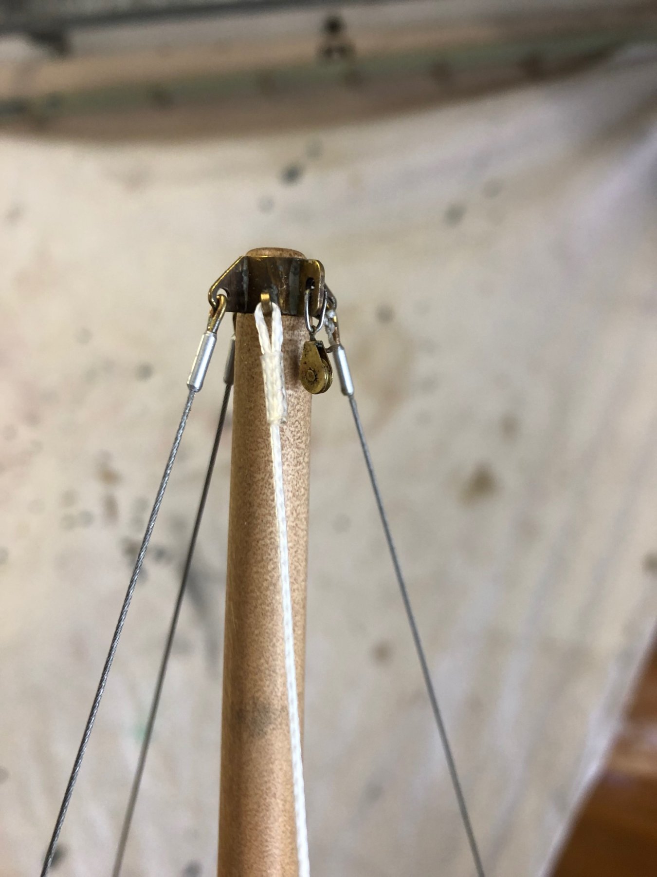
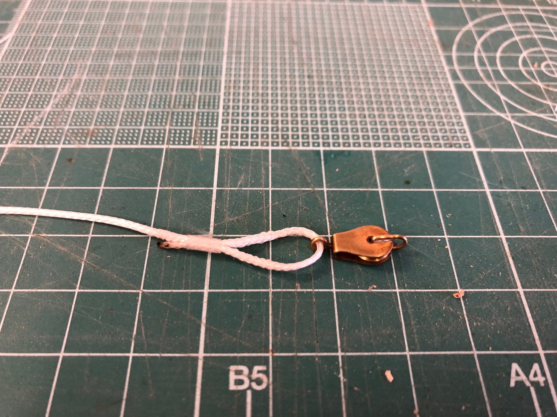
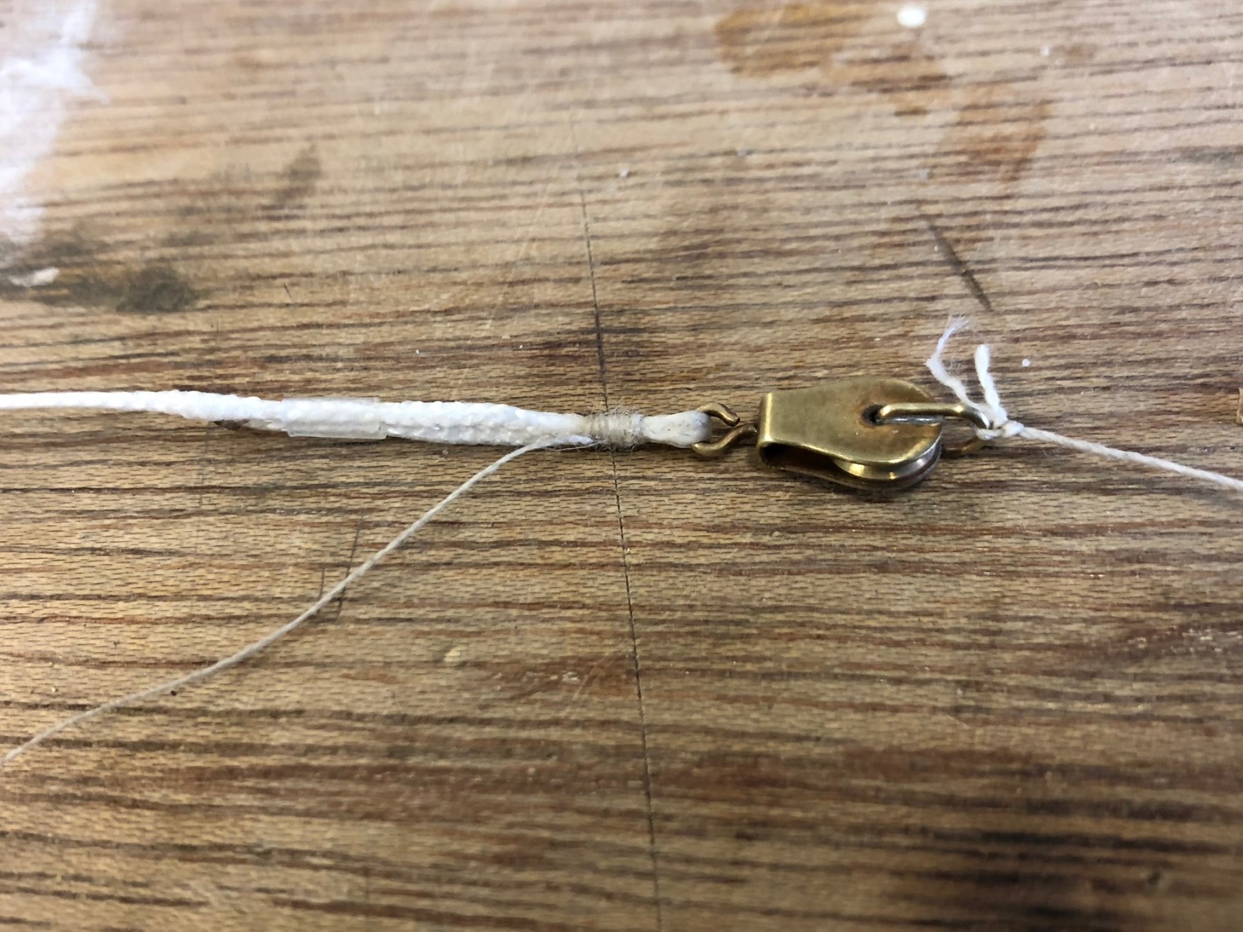
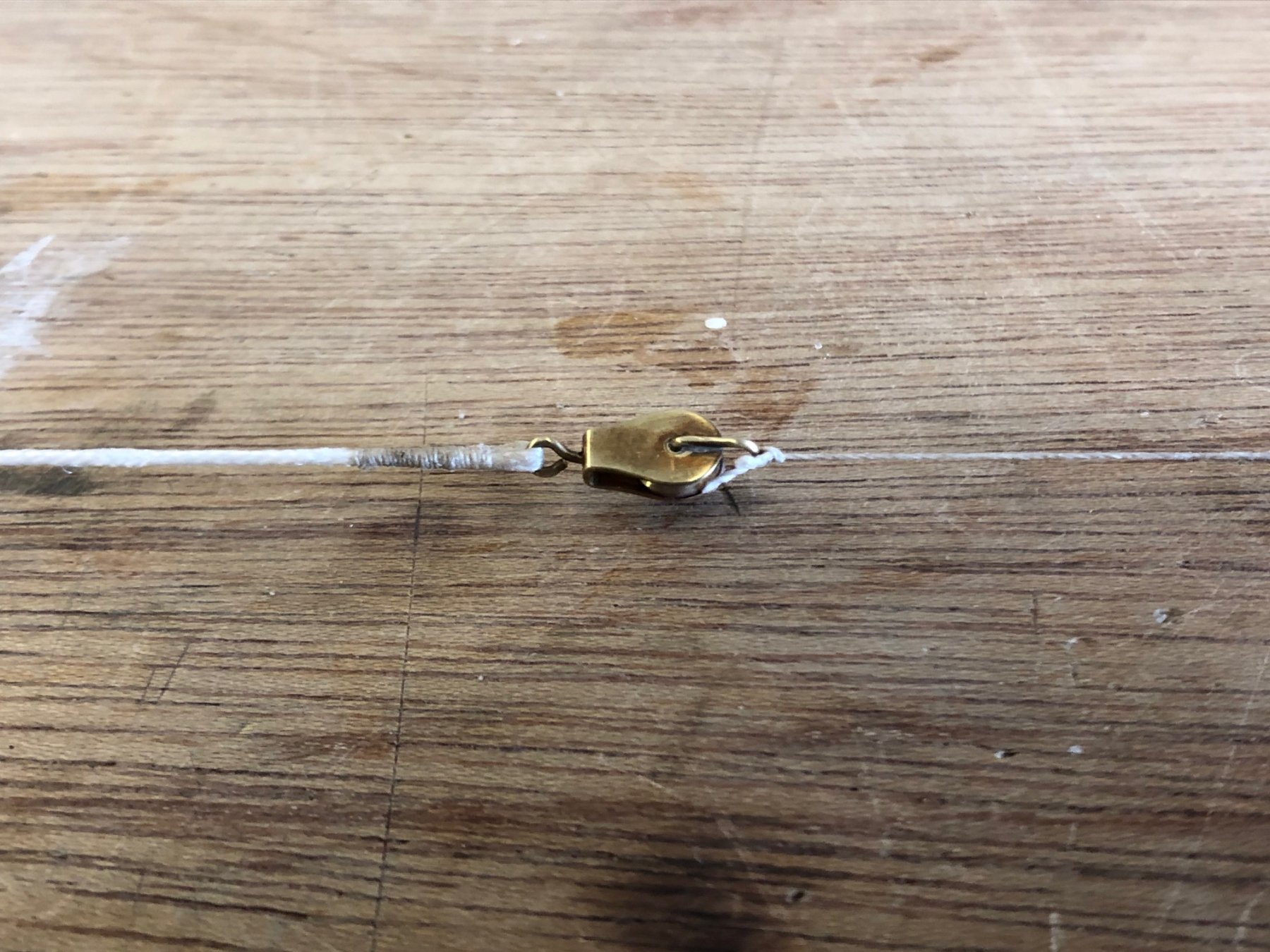
I've been working on the running backstays, doing the backstays themselves. The backstays are made from 1mm braided rope from Harbor Models (US), it replicates braided modern rope. Initially I tried some clear heat shrink tube for simplicity at the mast head end but it looked too bulky. Access is tight so I thought it might be ok, but then changed direction & also came up with a simple method that helped the process & used the heat shrink tube. Firstly, heat on a small piece of tube well below the whipping. Start the whipping, secure with a couple of hitches & put some dilute glue on to hold. Remove the tube & cut the tails off, with a tapered end; Then finish off the whipping. My whipping is a bit rough, definitely more agricultural that sophisticated but it's a better result than the tube. This process helped a lot because temporarily holding the rope while you start it off made it easier. thanks, Mark


- 411 replies
-
- 13
-
-
Hi John, best wishes to you & good to hear from you. Hi Vaddoc, the issue of simplicity is an interesting one for me: I've tried to imagine the person who commissioned this yacht to be built as having some money but not enough to go mad, so in my imagination some details would be done to save money here & there. Also I feel that more complex fittings don't always add to a boat's beauty, the Herreshoff Buzzards Bay 25 is a particular example of severe simplicity & beauty.
-
this looks very interesting, I'll be happily following your build Mark
- 219 replies
-
- 3
-
-
- smack
- cross-section
- (and 2 more)
-
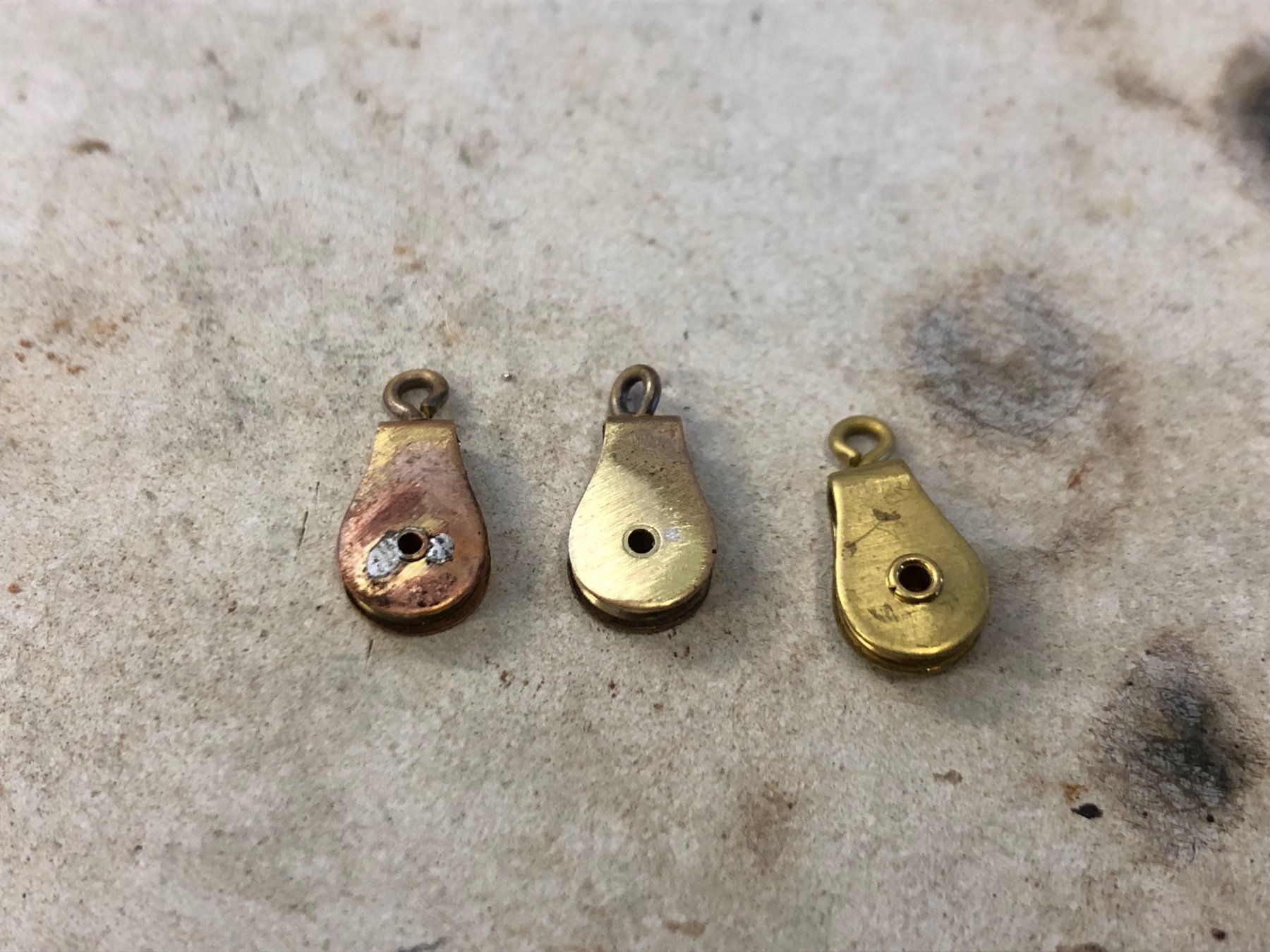
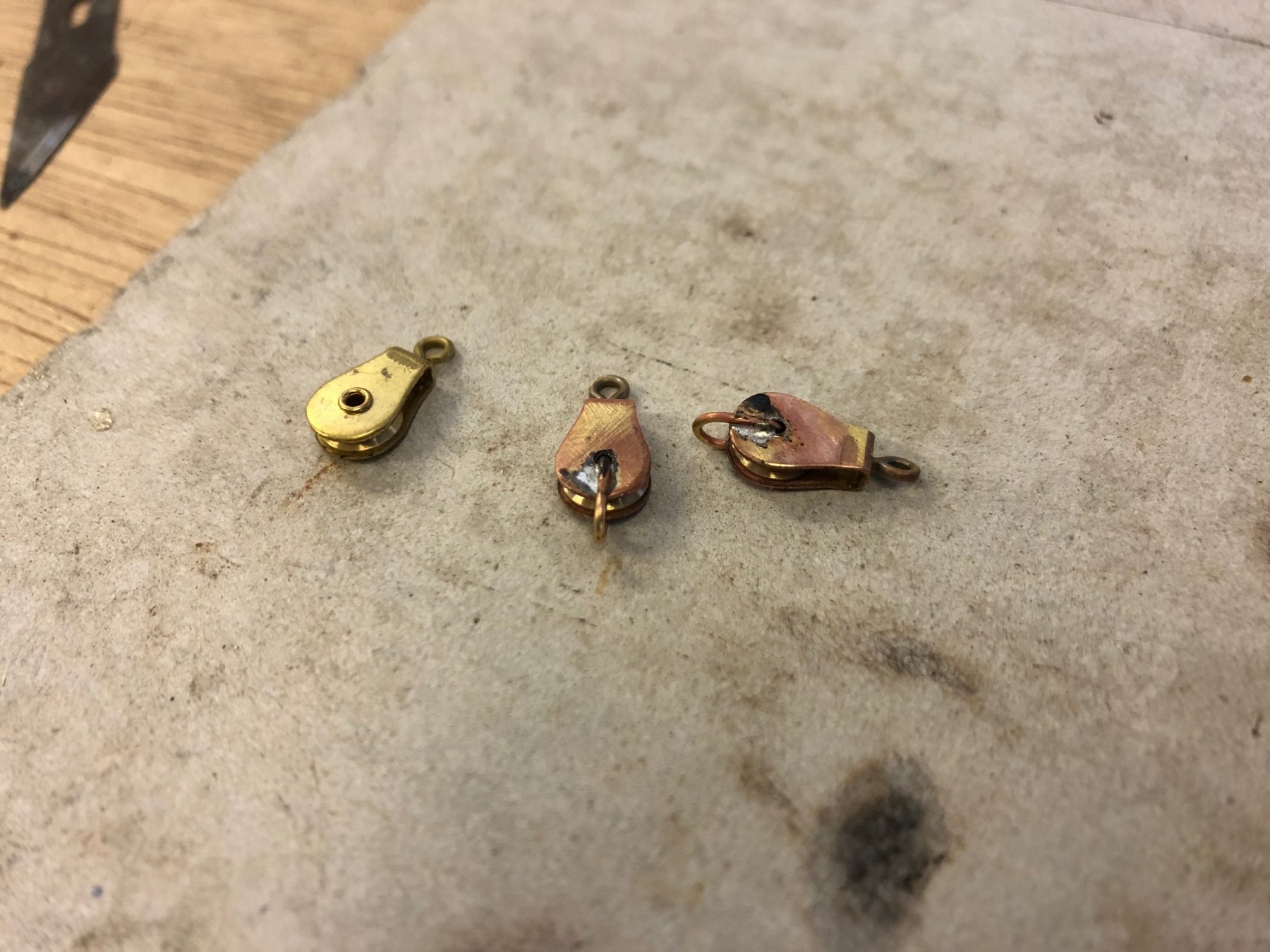
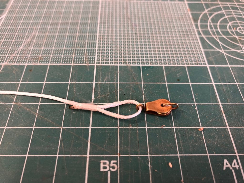
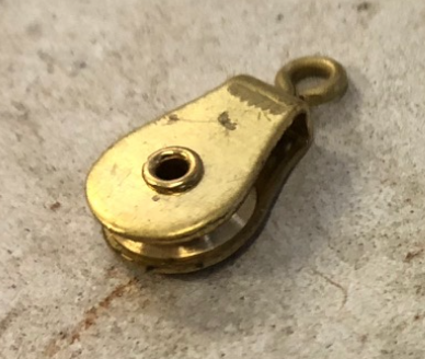
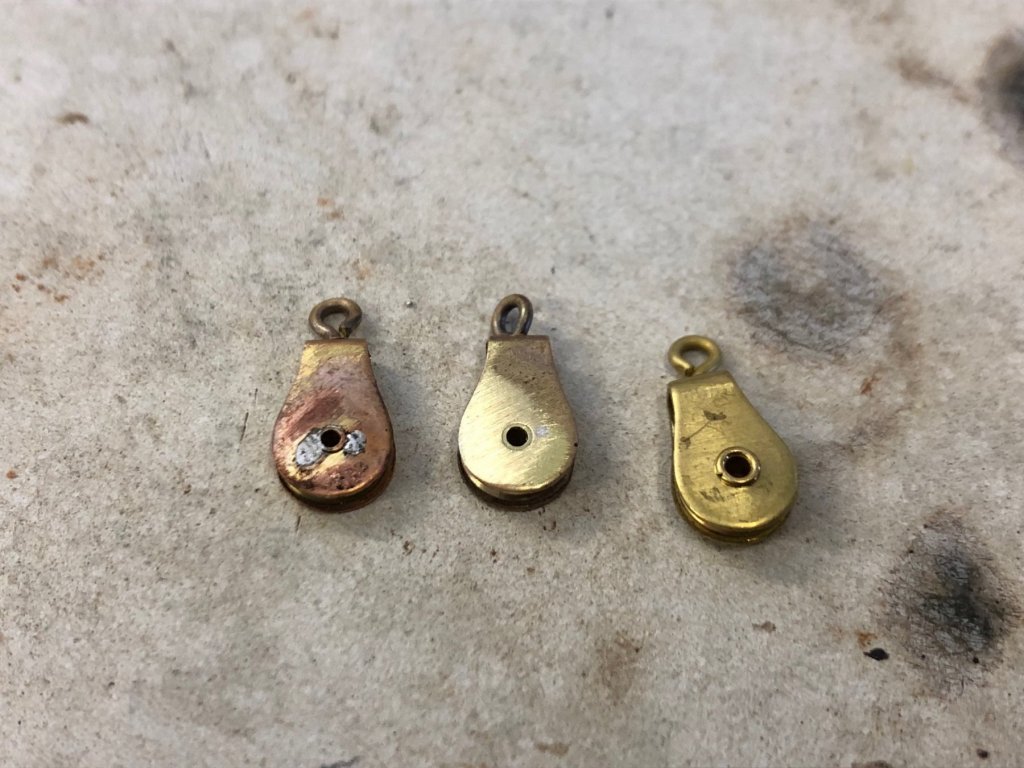
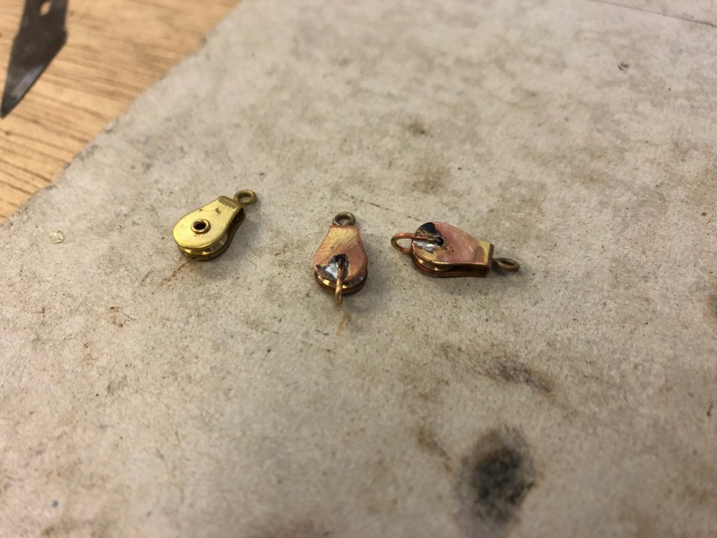
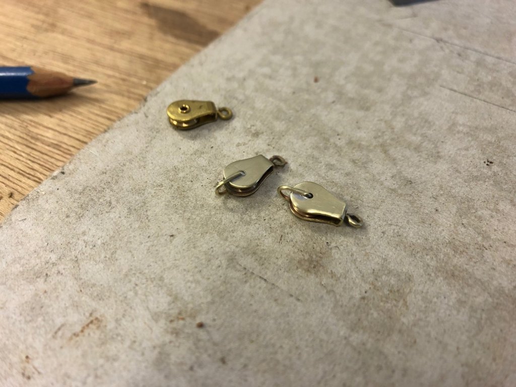
I've started on the running rigging & have been looking around at various ready made blocks, & also considering what I could do from scratch. The final call was to buy some off the shelf but improve their appearance. These are the blocks, the shape is ok but the flanged axle looks a bit crude. So I decided to sand off the flanges, & solder the axles in position. They immediately look better. These are for the running backstay tackles & I want 2 single blocks with beckets plus 2 doubles. The beckets came up well & look realistic. Originally I was going to laminate a thin piece of timber on both sides of the blocks but it wasn't looking good - too bulky - & I believe that full metal blocks were popular the 1960s, so no timber facings, at least on these blocks. The doubles are two blocks soldered together, with a square U bracket for fixing to the chainplate. The tackle set temporarily up to see how well it leads, & I'm happy that the double block loads the chainplate vertically as I'd hoped. The line from the double block to the winch will need another small leading block (I'm holding a rod to show the necessary deflection in rope angle) otherwise the winch would get riding turns every time. Thanks all,


- 411 replies
-
- 17
-
-
Hi Maury that's a very large centreboard, it would weight a lot. I like the sounds of the vertical tackle: having used some systems that are a tackle system laid horizontally on top of the case the angles are usually quite poor & to raise the board so you've got a mechanical disadvantage. I would think a tackle system has some advantages over a drum, the simplicity of using common hardware.
-
Hi Steven on the anchor, is the 2nd aperture down from the ring to house a lateral bar? - the design looks very much like a modern kedge anchor (which has the hole to house a removable lateral bar). Mark
-
15' Dinghy by Bedford - FINISHED - 1:1 scale
Mark Pearse replied to Bedford's topic in Non-ship/categorised builds
Hi Bedford nice just got nicer. Very pretty lines, but capacity too. The beach picture reminded me of an aching technique I used with a small sailing boat on beach picnics: the usual anchor with 5m of chain plus separately the smallest size sand anchor on light 3-strand. Approaching the beach I'd drop the anchor with chain 30m from shore, row in & get out in the shallows; bury the small anchor above the tide in the beach sand. The chain pulls the boat away from shore but you can pull the boat back towards you. -
Hi Steven, there is an argument against the entire deck being spaced - bracing. Decking laid side by side has tremendous bracing & would help in stabilising the hull. It's not fo certain the hulls would have need bracing, but a long skinny hull would probably benefit from it. It would not need to be full width - a centre strip of solid decking would do a lot - like a big piece of laminated timber laid flat. Mark