

popeye2sea
-
Posts
1,935 -
Joined
-
Last visited
Content Type
Profiles
Forums
Gallery
Events
Everything posted by popeye2sea
-
 Yes, the older method of increasing or decreasing sail was to add or subtract from the bottom of the sail. The exact opposite of reefing which is essentially reducing the sail at the top of the sail. With the old method the lower yard had to be movable on a regular basis. The parral provides rollers to assist in lowering the yard while maintaining control. When reefing became more of the norm, lowering the course yards was no longer necessary. Le Soleil Royale was right at that transitional phase when reefing started to come into use. BTW, reefing causes footropes to start being used also. Before that the sailor used to walk out along the top of the yard. Regards, Henry
- 1,508 replies
-
- 1
-

-
- Le Soleil Royal
- Heller
- (and 1 more)
-
For ships of HMS Victory vintage, there is no expectation of lowering the course yards on a regular basis, hence no need for parrals. There remains a need to truss the yard in towards the mast so truss tackles ( or tackle truss?) are employed. Regards, Henry
-
That's a beautiful model. Keep up the great work.
- 1,508 replies
-
- 1
-
-
- Le Soleil Royal
- Heller
- (and 1 more)
-
Bill, Nice story. I'm pleased that you ran with it. The ship is looking great. And the gun crews will be the envy of the fleet! Regards, Henry
- 1,508 replies
-
- 1
-
-
- Le Soleil Royal
- Heller
- (and 1 more)
-
You are correct Allan. Topsails have no tack. The sheet holds them confined to the lower yard. Regards, Henry
-
Remington Industries
popeye2sea replied to Roger Pellett's topic in Metal Work, Soldering and Metal Fittings
Good find. Thanks! Regards, Henry -
Envision a scenario whereby the ship is underway and exercising the great guns. Picture this - The 1st Lieutenant orders the guns to be exercised by division. The second LT, who is in charge of the second deck battery, orders the first division, in this case it could be the first four guns on the port side, to prime, load, and fire. He will compare their best time with the other divisions for a bit of competition. Bottom line. Display them however you choose. Anything can be justified with a good narrative. Regards, Henry
- 1,508 replies
-
- 3
-
-
- Le Soleil Royal
- Heller
- (and 1 more)
-
BTW, I made a spreadsheet of all of the rigging plan, calling out all of the blocks and fittings needed. It helped me greatly to figure out how the rigging runs and what blocks to put where. I can more easily search the spreadsheet for a particular line than try and follow it through multiple pages of the Heller instruction booklet. Regards, Henry
- 1,508 replies
-
- 1
-

-
- Le Soleil Royal
- Heller
- (and 1 more)
-
Not sure if my rigging plan compares to yours but here is what mine shows for lines leading through the saddle. Saddle port side top to bottom. duplicate on starboard side except 1011 1011 Fore topmast stay tackle 1018 Spritsail brace 1098 Fore sail bowline 1088 Spritsail clew line Rack Block ( on gammoning) port side top to bottom 1023 Spritsail yard lift/spritsail topsail sheet 1020 Spritsail topsail brace 1096 Fore topsail bowline 1094 Fore topgallant bowline 1085 Spritsail topsail clew line There may be additional lines run through there but I would have to do a more complete search of the plan. Hope that helps Regards, Henry
- 1,508 replies
-
- 2
-
-
- Le Soleil Royal
- Heller
- (and 1 more)
-
Take them through the saddle fairlead. That is it's intended purpose. Other parts of the running rigging for the spritsail and spritsail topsail will go through the rack block on the gammoning. Regards, Henry
-
The spritsail yard looks great. Regards, Henry
-
"I’ve seen all the drawings and diagrams that show the gun tackle ropes in neat inspection-ready coils, but I wonder what the gun crews really did with their lines. I didn’t glue the coils down all that securely just in case I see something that changes my mind." When in action, coils like you have, or Flemish coils ( the ones that look like spirals) are a big no-no. When the gun fires the side tackles act as a sort of recoil brake. If the lines are coiled they will kink and jam when the rope starts to run out. One way to avoid this is to flake (or fake) down the rope. You can look this up in the Ashley Book of Knots or other knotting reference. There are videos on you tube that show it, but do not use the modern rope climber method of flaking which, to my sailors eye, just looks like an unusable puddle of rope on the deck. Use the proper nautical method still used today to make up ropes to run freely. Regards, Henry
- 106 replies
-
- 5
-
-
-
- Soleil Royal
- Ship-of-the-line
- (and 2 more)
-
I can't leave them out. And I would like to make them as functional as possible. Finding the appropriate size beads for the parrels is not easy at 1:100 scale. Henry
- 1,508 replies
-
- 1
-
-
- Le Soleil Royal
- Heller
- (and 1 more)
-
The cleats are added to the yard prior to rigging. The straps inside of the cleats are selvagees (a continuous loop of rope) that is passed around the yard within the cleat before one end is inserted through the other to form the strap that takes the halliard tye. The quarter blocks for the topsail sheets are stropped with two eyes that pass around the fore and aft sides of the yard to be joined by a rose lashing atop the yard. When I get to that point I will add cleats as well to the upper yards. I believe that they are open or horn cleats as opposed to the closed cleat for the courses. Yes, there will have to be determined an appropriate belaying point for the truss pendant tackle. On my rigging plan there are two eyebolts either side of the fore mast, labelled a1 and a2 that do not appear to be used that I will repurpose for the lower block hooks. On the main there are two eyebolts designated for studdingsail halliards, that I am not using, so I will repurpose them for truss tackles. BTW, I am still not certain that the parrel falls for the upper yards came all the way to the deck. I have read references that they terminate in the tops. Regards, Henry P.S. I am impressed by advances you have made in correct terminology usage in the short time since this build log started.
- 1,508 replies
-
- 1
-
-
- Le Soleil Royal
- Heller
- (and 1 more)
-
Pete, When not ready for battle the cannons would have been secured by lashing to the bulwarks of the ship. The free ends of the side tackles would be frapped (wrapped) around the fall. Regards, Henry
-
I knew you were going for the "non-serieux" line. I just thought that not too many people know what ded. reckoning really is. Henry
- 106 replies
-
- 1
-
-
- Soleil Royal
- Ship-of-the-line
- (and 2 more)
-
Looks like you've got all the stays. Great job so far. Regards, Henry
-
John, Your ability to bring the story to life is outstanding as is your ability to bring the frieze work to life. I am in awe of your decal work. The ship looks amazing. All of these other SR build logs have got me really wanting to get back to my build. Regards, Henry P.S. Dead reckoning is actually Ded. Reckoning and is a shortened spelling of deduced reckoning which is continuing the plotting of a course line forward based on the information obtained from your last good position fix. The ded reckoning plot line is marked at set time intervals to estimate what your deduced position will be. When you actually get to that time point and take a position fix you can then calculate based on the difference between that fix and the deduced point what your set and drift are. In other words how much you are being blown off course by wind and current. Then you can correct your course accordingly. So endeth the lesson on navigation. Regards,
- 106 replies
-
- 5
-
-

-
- Soleil Royal
- Ship-of-the-line
- (and 2 more)
-
Perhaps yes, handrails for the upper decks, for instance leading up to the quarter deck and poop. But, I wonder if they were fitted for going below. A single grab rail in an overhead beam would suffice for many applications. Regards, Henry
-
The lower yard should be hung right at the level of the catharpins. In fact, that is one of the functions of the catharpins. To swifter in the shrouds to allow the yard to be able to brace up to its maximum extent. Also, the foremost shroud would not be placed so that it lies before the mast. Not something you can correct for the Heller kit. Regards, Henry
- 1,508 replies
-
- 1
-
-
- Le Soleil Royal
- Heller
- (and 1 more)
-
That was the job of the gunner and his mates. Regards, Henry
-
Marines were definitely in a separate administrative and operational organization. They only received orders and disciplinary actions from the Marine officers. However the Marine officers answered to the Captain of the ship who was in ultimate charge of everything that went on in his ship. In the Royal Navy Marines could also be called upon to man the cannons during battle. Regards, Henry
-
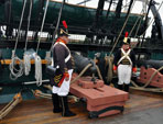
That was pretty much it. Standing guard or drilling. Marines did not stand watches like the sailors. Maintaining their uniforms and weapons also occupied some of their time. Marines uniforms had to look in top condition all the time. Polishing brass and whitening leathers takes a good amount of time. Trust me, I have to do it frequently. And I use modern cleaners and whiteners. My profile pic is me in 1812 US Marine uniform. Regards, Henry
-
My wife and I spent 3 days in Edinburgh and then rented a car for a grand tour of the highlands. Culross, Stirling, Loch Lomond, Loch Fyne, Inverary, Kilmartin Glen, Fort William, Glen Finnan, Isle of Skye, Inverness, Culloden, Loch Ness, Aberdeen. Then back to Edinburgh on our anniversary. Returned home yesterday. Regards,
- 1,508 replies
-
- 3
-
-
-
- Le Soleil Royal
- Heller
- (and 1 more)