
HOLIDAY DONATION DRIVE - SUPPORT MSW - DO YOUR PART TO KEEP THIS GREAT FORUM GOING! (89 donations so far out of 49,000 members - C'mon guys!)
×

popeye2sea
-
Posts
1,935 -
Joined
-
Last visited
Content Type
Profiles
Forums
Gallery
Events
Everything posted by popeye2sea
-
 Sorry I have not had a chance to reply over the last two weeks. I was on vacation in Scotland. I agree with Marc and Ian the topmast trestle and cross trees are too long and should be trimmed back. Also the rear hole should fit closely around the topmast head while the forward hole should admit the square lower section of the topgallant mast. For those reasons I will probably fabricate my own cross trees. Also I have never been a fan of those round sections of the mast that are supposed to represent the cheeks and hounds. I think those are another Hellerism. Regards, Henry
- 1,508 replies
-
- 2
-

-
- Le Soleil Royal
- Heller
- (and 1 more)
-
USS Constitution vs Cutty Sark - which to build first?
popeye2sea replied to Frank Burroughs's topic in Plastic model kits
I don't agree. If you rig Cutty Sark the way it is supposed to be, with it's combination of chain, wire, and rope rigging, and add all the missing fittings for various whip tackles that are not depicted in the plan, it is a far more complex rig than Constitution. Regards, Henry -
Welcome. Looking forward to your added research and knowledge. And the build looks great too! Regards, Henry
- 103 replies
-
- 6
-
-
- Soleil Royal
- Ship-of-the-line
- (and 2 more)
-
You may not need that. Add a piece of metal rod into the lower yards when assembled to add some weight and the halyard and lifts will hold them just fine. Replace the upper yards with wood to give them some extra heft as well. If your setting sails then the sheets and clews will hold the upper yards against the upward pull of the halyards. You may have to resort to pins if you are not rigging sails. Regards, Henry
- 1,508 replies
-
- 1
-
-
- Le Soleil Royal
- Heller
- (and 1 more)
-
There are parrels fitted to all the yards. They hold the yards in against the mast. So if you are going to fit the yards as you proceed up the masts, then yes you will need to fit the parrels. I would suggest that you put all of the fittings and rigging on the yards before you put the yards on the ship. You don't necessarily need to belay all the rigging right away but you should at least attach everything to the spars. I would even go so far as to attach braces and other rigging to each stay before they are fitted to each mast. I would wait to brace all the yards around until all the yards are on the ship so that they can be aligned properly. Brace round first, then belay. You will run into problems if you belay all the other rigging for the sails and THEN brace the yards. Some of the other lines will be pulled too taut. The curved piece at the top of the mast is called the cap and the large holes in it will take the tye, which is the rope that hauls up and holds up the lower yards. It is one long piece of rope whose ends pass over the cap, down through those holes, and are hitched to the yard just inside the quarter cleats. The center of the tye passes through the upper hole of a ramshead block, which is a large triple sheave block that hangs aft of the mast and the halyard is rove through this and communicates with the knight on the deck. Once this is set up it should need no further adjustment. Regards, Henry
- 1,508 replies
-
- 2
-
-
- Le Soleil Royal
- Heller
- (and 1 more)
-
No, not asking for trouble. In fact, having the yards braced in on a port tack is how I will be setting mine. Maybe not quite close hauled, but perhaps a point or so off the wind. (Nautical terms liberally placed) translation: Braced-in - having hauled in on the yard braces to swing the yards oblique to the mast. Port tack - sailing so that the wind is on the port side forward, resulting in the port side tack line being hauled down taut. Close-hauled - sailing with the yards fully braced in, as close to the wind as possible. One point free or one point off - Sailing with the wind one point, 11.25 degrees, off of close hauled. The compass rose has 360 degrees and is divided into 32 points, North, N by NE, NNE, etc. A square rigged ship can only sail as close as 45 deg. up wind. Sailing a point free allows the leeway to come up a bit closer to the wind if the need arise, as in an emergency or a battle. So endeth the lesson Setting the sails braced round in this manner will only mean that you have to pay attention to how tight you make some lines like the lee bow lines on the sails. Otherwise, have at it. I think it will look great. Regards, Henry
- 1,508 replies
-
- 1
-
-
- Le Soleil Royal
- Heller
- (and 1 more)
-
Crossing the yards is nautical speak for hoisting the yards aloft into their positions lying "across" the masts. In other words, suspended by their halyards, jeers, slings and lifts. Regards, Henry
-
I believe you would call those tween decks because they are partial decks between the other full decks. Although, usually tween decks would run side to side and not longitudinally along one side. Regards, Henry
-
The orlop, by definition, is the lowest deck of a ship. Therefore it lies just above the hold. The hold is where the storage casks would be found. The carpenter, sail maker, cooper, and boatswain, may have supplies and work areas on the orlop deck. Regards, Henry
-
Here is my interpretation of the futtock shroud rigging. Don't follow Heller. It would be better to fit a metal strop to the lower deadeye and either hook or seize the futtock shroud to it. Anderson mentions that this was the rule by 1620 or so. Next I would fit a futtock stave. It should extend across all of the shrouds and be seized to each. The futtock shrouds should pass around the futtock stave before being seized to the shroud below the staff. Last, although Anderson does mention in his very last sentence regarding upper catharpins, that the French seem to have dispensed with them up to about 1700, I would consider fitting them because it will help to hold the shrouds in against the pull of the futtock shrouds. The catharpins should be fitted before the futtock shrouds and be seized to the futtock stave. I intend to fit them on my build. Sort of along the same principle as adding the bobstay on the bowsprit. It is just going to help get the rigging more shipshape and Bristol fashion. Regards, Henry
- 1,508 replies
-
- 1
-

-
- Le Soleil Royal
- Heller
- (and 1 more)
-
I would fit the tops with all their gear pre assembled, and the remaining rigging that goes around the mast heads. Once the lower masts are relatively complete and secure, then I would move on to the sprit yards and the topmasts. You could consider crossing the main yard. The reasoning here is that it will become increasingly difficult to get rigging in close to the masts as you go along. Most of the rigging belays from the centerline outwards as you move up the masts. But, everyone has their own order of doing the rigging. Regards, Henry
- 1,508 replies
-
- 1
-
-
- Le Soleil Royal
- Heller
- (and 1 more)
-
It is unanimous then. I fully concur with Michael and Marc.
-
Bill, now that I look at your last photo I see that Michael has a good point. I was going to tell you that the pendants were rigged before the shrouds went over the mast head. You can simply seize the upper block of the burton tackles to the thimbles on your pendants, which are already hanging inside the shrouds. Regards, Henry
-
The burton tackles look great. I hate to bear bad news, but they should come down inside the shrouds. Regards, Henry
- 1,508 replies
-
- 1
-

-
- Le Soleil Royal
- Heller
- (and 1 more)
-
I prefer the classic PEMDAS order of operations: Paint Each Module Drink A Scotch🤣
-
Bill, Yes, the hooks on the blocks for the mast tackles (also called burton tackles) attach to the eyebolts in the channels, but I do not recall where the fall belays. You could hitch it around the nearest shroud above the deadeyes. Regards, Henry
- 1,508 replies
-
- 1
-
-
- Le Soleil Royal
- Heller
- (and 1 more)
-
Mad For Glory, A Heart of Darkness in the War of 1812, by Robert Booth. The fascinating true story of a US Naval Captain, Captain David Porter, who went rogue with his warship, USS Essex and terrorized the Pacific Ocean. The longest, strangest naval adventure in American History. Regards, Henry
-
Allan, I think in this case the use of tarred line is appropriate. These are crows feet on a back stay and do not 'run' at all. Regards, Henry
- 1,508 replies
-
- 2
-
-
- Le Soleil Royal
- Heller
- (and 1 more)
-
That's really nice work. I'm going to have to tinker with mine now. Regards, Henry
- 1,508 replies
-
- 1
-
-
- Le Soleil Royal
- Heller
- (and 1 more)
-
That looks great. Good job!
-
Yup, looks good to me. If you manage to put a bit more tension on the stay by holding down the bowsprit with a bobstay it should bring things into line that much nicer. Just be careful to not over tension the stay and pull your masts out of alignment. Don't wait on me to see what I will do. It will be several more months before I can even think about re-starting my modeling. Regards, Henry
- 1,508 replies
-
- 1
-
-
- Le Soleil Royal
- Heller
- (and 1 more)
-
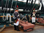
Great little sanding block
popeye2sea replied to Papa's topic in Modeling tools and Workshop Equipment
Many years ago I picked up a child's wooden jigsaw puzzle at a craft store. The multiple shapes and angles come in very handy as a sanding block. Regards, Henry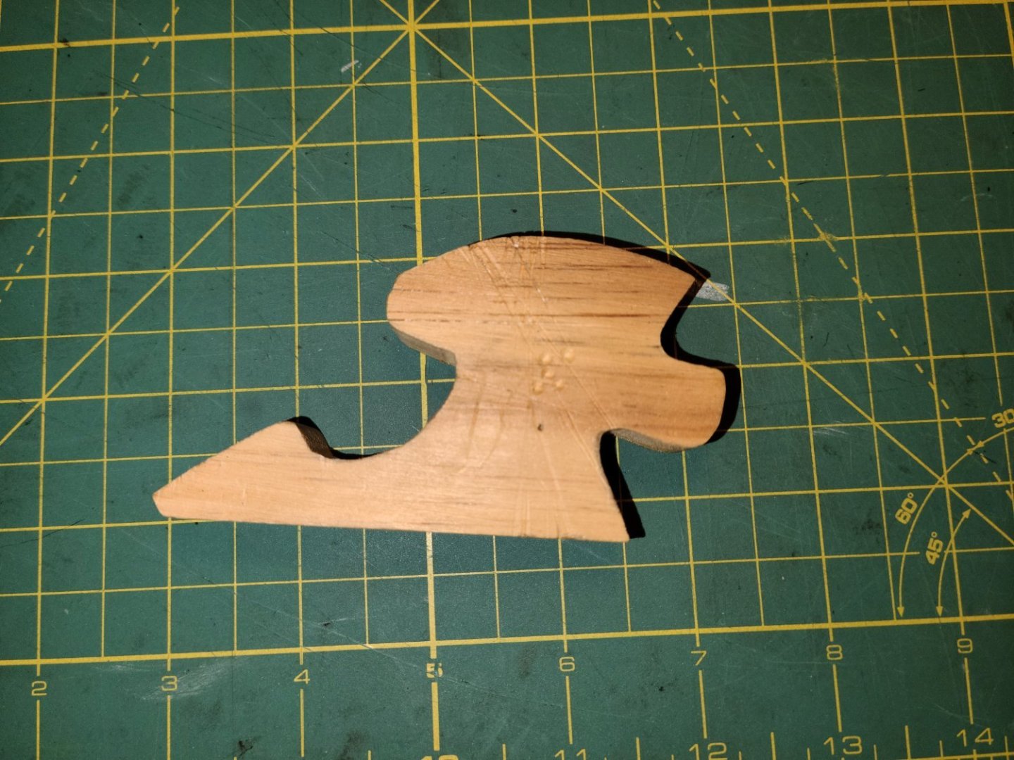
-
The rope thickness you used for the last pic looks good. It is difficult getting the stay to remain straight. I am going to be adding a bob stay to the bowsprit. They were just coming into vogue during this period. That should help offset the upward pull of the fore stay and allow for a bit more tension on the stay to keep it straight. Regards, Henry
- 1,508 replies
-
- 1
-
-
- Le Soleil Royal
- Heller
- (and 1 more)
-
That looks good. If I might make a suggestion regarding blocks in general. The lay of the lines can be improved by slightly rounding the sharp edge of the hole where it enters the groove on the block. This will allow the rope to lay in closer to the block and not have that unnatural broad parabola shape. Regards, Henry
- 1,508 replies
-
- 2
-
-
-
- Le Soleil Royal
- Heller
- (and 1 more)


