
HOLIDAY DONATION DRIVE - SUPPORT MSW - DO YOUR PART TO KEEP THIS GREAT FORUM GOING! (89 donations so far out of 49,000 members - C'mon guys!)
×

popeye2sea
-
Posts
1,935 -
Joined
-
Last visited
Content Type
Profiles
Forums
Gallery
Events
Everything posted by popeye2sea
-
This is also the period when riggers went crazy with crows feet everywhere: braces, backstays, lifts, bowlines, martinets. Your conjecture fits right in. Regards, Henry
-
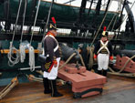
 Just a quick note on my draping of the rope coils across the barrels. I do not know if that was actually done. It was a bit of artistic license to highlight the difference from the cannons on the other side that are run out and in -battery ready to fire. The coils draped over the barrels are intended to show cannons that are readied on the un-engaged side of a battle. Regards, Henry
- 1,508 replies
-
- 1
-

-
- Le Soleil Royal
- Heller
- (and 1 more)
-
Regarding your question about the fall of the tackle. The fall is the rope that gets rove through the blocks. There are two ends to every piece of running rigging; the standing end which is fixed to an object, and the working end which is the end that gets hauled upon. In the case of the tackle fall, the standing end gets hitched to the loop (the becket) at the bottom of the single block. At the other end of the block an eye in the strop takes the hook. The fall is then rove through one hole in the double block, back through the hole in the single block and thence through the second hole of the double block. The working end (hauling part) of the rope is then coiled (flaked) on the deck. What I was referring to in my previous post is that if you make that hitch overly large you will not be able to get your blocks close enough together. The hitch takes up some of that space being part of that first leg of the tackle from the single to the double block. The other place that will eat up your available space is if you make your hooks too long. You will then not have enough room for the tackle between. When I was making my hooks I modified a pair of I think they are called ring nose pliers. I ground down one tip to about a half millimeter round. That is the tool I make all my hooks and eyes with. The hooks end up being about 1.5mm or there about long. So if you are using 2.5mm blocks with the hooks, just the hardware without the strops and fall is already 8mm long. You may quickly run out of room for your tackles. One other thing to note. I see you are using blocks with only one hole. A common mistake is how you orient the blocks when rigging. The hole represents the throat of the block that is at the top of the round sheave that the rope rides around in the block. This hole will always be at the eye end of the block. In other words you want the holes of the two tackle blocks to be furthest away from each other. Visually the rope will have the appearance of laying along both sides of the block. If your rope appears to go through the hole and then immediately away from the block with the bulk of the block hanging out beyond then you have your blocks rove and stropped upside down. Regards, Henry
- 1,508 replies
-
- 1
-

-
- Le Soleil Royal
- Heller
- (and 1 more)
-
Your analysis is 100% spot on. The breeching is not usually removed from the carriage or bulkhead so it is semi-permanently attached with a hitch and seizing. The tackles are frequently removed and/or shifted so they have hooks in the eye of the strop. 2.5mm blocks should work as long as you are careful with the attachment of the tackle fall to the single block and the length of your hooks. You may find that there is insufficient drift between the two blocks to look good. The ring bolt on the deck can be substituted with a plain eyebolt. Regards, Henry
- 1,508 replies
-
- 1
-
-
- Le Soleil Royal
- Heller
- (and 1 more)
-
Yes, the in-haul tackle is the one on the rear of the carriage. The other two are the out-haul tackles. The breeching rope is a heavy rope. Much thicker than the tackle falls. It has to resist and check the recoil of the cannon when fired. The length should be enough to allow about 12 to 18 inches between the muzzle and the gun port sill to allow for loading. The gun tackles falls are flaked down on the deck before firing the gun so that when the gun recoils the rope will not kink and bind when the the fall runs through the blocks. The tackles act as sort of a brake to absorb some of the energy of the recoil. I would not zig-zag the position of the cannons. Perhaps you can do what I did and show the guns run out into battery position for firing on one side of the ship and run in for loading on the other? Regards, Henry
-
If you notice on mine. The tackle fall was left long enough to make a coil or to flake down on to the deck ready for running. If you decide to do this, make sure the hauling part of the tackle fall comes out of the block away from the gun carriage. It will lay down for the coil much easier that way. For the in-haul tackle it does not matter what side the fall comes out on. Rigging the tackles is fairly straightforward. Installing them is just a matter of putting a drop of CA glue on each hook to fasten it to the ring. Otherwise the hooks tend to jump out of the rings as you manipulate the tackles. For me the hardest parts were hitching and seizing the breeching rope to the ring bolt and also getting the flaked coils to lay correctly on the deck. You may also find it a bit fiddly to hitch the tackle fall to the becket of the single block. The becket is the loop at the bottom of the block opposite the eye where the hook is. Easiest is to attach the tackle fall to the becket while you are stropping the block. That way the single block is completely ready for reeving the tackle with the hook in the eye and the fall attached. I hope that makes sense. Regards, Henry
-
I think they call this the third battery deck, the ones below being the first and second battery decks. Above that is the quarter deck then the roundhouse (?) then the poop deck. Regards, Henry Oops, sorry Marc, I didn't see that you had already replied.
-
Two-blocking is when the two blocks that make up the tackle are drawn together until they touch. The result is a jambed up tackle that needs to be manually overhauled to work again. BTW, the wrapping of rope around the ring of an anchor is called puddening. Regards, Henry
-
I raised the exact question in my build log. Never did find and answer. Regards, Henry
-
Bill, I went crazy making my own carriage bolts by hand. Extra points for craziness awarded for peening each carriage bolt head by hand with a miniature ball peen hammer on a jewelers anvil. You certainly do not need to do all that. Could probably achieve the same effect with a blob of plastic or even glue, painted black. I got smarter (lazier) making the cap squares for holding the trunnions down out of black paper (not installed yet). Use the smallest blocks and rigging rope you can find for the gun tackles. My blocks are 2mm from Syren. I know it is kind of too late, but, it is much easier to seize the breeching rope through the ring bolt and then just insert the ring bolt into the bulkhead to install the cannon. Alternatively, at this point you can make small rings and seize the breeching to them. When you go to install the cannons you can just spread the ring a bit to fit through the eyebolt you have already installed in the bulkhead. It all takes a bit of finesse and a lot of patience. Regards, Henry
- 196 replies
-
- 1
-
-
- plastic
- soleil royal
- (and 2 more)
-
I still say it's impossible. Let's go the other way. Say you are lowering the main yard. You have a six part tackle at the mast head. In order to bring that yard down to the deck you need that hauling part to be at least 6 times longer than the distance the block needs to travel. You would get stopped as soon as the block from the lower tackle reaches the lower jeer block and not be able to go any further. Regards, Henry
-
You all make some fine points about different tackle systems, especially about the necessity for a lead block to change the direction of the pull. But the point I was trying to make about having a tackle up at the yard and also down at the deck is this. It is not done. For example, what would happen if you haul the line. The two blocks of the tackle move closer together right? Now what if the upper set, or the lower set, two-blocks (touch each other) before the haul is finished. That tackle would then jamb and your hauling is done until you un-jamb the blocks. Plus, it is overkill. Even for the very heavy lower yard, the two treble jeer block tackles provide sufficient purchase to raise the yard. Why go through all the extra effort and material for the additional tackles. Regards, Henry
-
I think the rigging instructions are incorrect (what a surprise). There should not be an additional tackle at the deck level. The tackles at the mast heads will suffice. The hauling part of the halyards should come down aft of the mast and belay to the fife rail. Regards, Henry
-
Check out the build log by GJDale. You will find some excellent hints and tips. Regards, Henry
-
I agree wholeheartedly with Marc. The join between the stern balconies and the quarter gallery is very tricky. It is best to mount the quarter galleries first and then match the balconies up to that. You can achieve a much better alignment. Once the outside edges are glued up, flow a line of plastic cement along the inside edge where the balcony meets the stern plate with a small brush to complete the join. Regards, Henry
- 1,508 replies
-
- 1
-
-
- Le Soleil Royal
- Heller
- (and 1 more)
-
I ignored the instructions and completed the stern with all the decorations except for the lanterns at the top of the taffrail. It makes no difference in the build order. Regards, Henry
- 1,508 replies
-
- 2
-
-
- Le Soleil Royal
- Heller
- (and 1 more)
-
The waterway was a necessary feature to avoid exposing the end grain of the planking to standing water which helps to minimize rot. Regards, Henry
- 1,508 replies
-
- 1
-
-
- Le Soleil Royal
- Heller
- (and 1 more)
-
Don't worry about the anchor cable. It doesn't need to be attached to anything inside. You can just let the end sit inside. There will be no tension on it. Or simply glue it into the hawse hole. Regards, Henry
-
Securing Ropes Wrapped Around Masts
popeye2sea replied to acaron41120's topic in Masting, rigging and sails
You can make the wooldings and secure them without glue in the folowing manner: Lay a bight of the line you are using along the mast. Make it a bit longer than the final width of the woolding. Make sure to leave a good length of the end to be able to grab on to later. Start taking turns of the woolding around the mast working towards the bight in the line. When you have the desired width for your woolding pass the working end through the bight. Now grab the end of the line you left long earlier and pull. This will draw the working end down behind the woolding and tighten the whole thing up. Trim the ends close to the top and bottom of the woolding. Done! Regards, Henry -
I have never read anything that gives a size for serving line. Regards, Henry
-
In Steel's Art of Rigging there are tables of rigging sizes given for ships of various tonnages and rig. In it the larger standing rigging allows seizings of up to 1-3/4 inch circ. with the smallest seizings being listed as just marline with no size given. Regards, Henry
-
I'm not entirely sure what you refer to as serving. Serving is sort of an outer covering applied to rope to keep the wet out of the strands. It is part of a system of coverings; worming, parceling, and serving. Seizings, on the other hand, are what is used to join two ropes, or two parts of a rope together side by side as in forming the eye at the top of the shroud pairs. I don't know what scale you are working in, but seizings were traditionally made using marline or other small stuff, so you will want to use the smallest line you can find. On my 1:100 scale model I am using fly tying monofilament. A typical round seizing was 7 or 9 turns followed by one less riding turns over them and then two crossing turns around the whole and between the two parts of the rope. The end of the seizing line was secured with a knot or hitch around the crossing turns. When putting the seizings on the masthead eyes for each shroud pair, the seizings should be put on so that the seizings do not overlap the one below. The idea was to prevent the seizings working (friction) against each other. The first seizing will come just below the bolster. The bolster is a piece of quarter round moulding on top of the trestle tree to ease the bending of the shroud eye over the top. To seize in a dead eye on the lower shroud there are three seizings. The first is called the throat seizing and it lays horizontally and holds the parts of the shroud together over the top of the deadeye. No crossing turns are used for a throat seizing. The second seizing is called the middle seizing and it is a round seizing clapped on midway between the deadeye and the end of the shroud. The last seizing is called the end seizing and is clapped on just below the end of the shroud. There is also a whipping put on the end of the shroud to keep it from unlaying. Sometimes the end of the shroud is leathered (capped). Regards, Henry
-
The only line I used the 2mm rope on was the main stay for my 1:100 Le Soleil Royal. Regards, Henry
-
The answer to this really depends on how accurate and to scale you want your rigging to be. There are a few spreadsheets on the site that will guide you on what sizes of rope were used where. Generally speaking the size ranges of the lines used run from the largest for the lower masts and yards to the smallest on the upper spars. You could end up using 5 or more rope sizes from 2.0mm to 0.25mm diameter. Personally, I am not a fan of using the Revell blocks. Regards, Henry
-
The bulk of the sail is pulled up in front of the yard by the hands. Each "grab" is accordion pleated on top of the yard. The bundled sail is then inserted into the last fold to form a sort of tight skin over all. The clews of the sail never actually go into the bundle and hang down beneath. Regards, Henry
