.JPG.ca33079f5815b861e67b9c2cccd37982.JPG)

Blue Ensign
-
Posts
4,575 -
Joined
-
Last visited
Content Type
Profiles
Forums
Gallery
Events
Everything posted by Blue Ensign
-
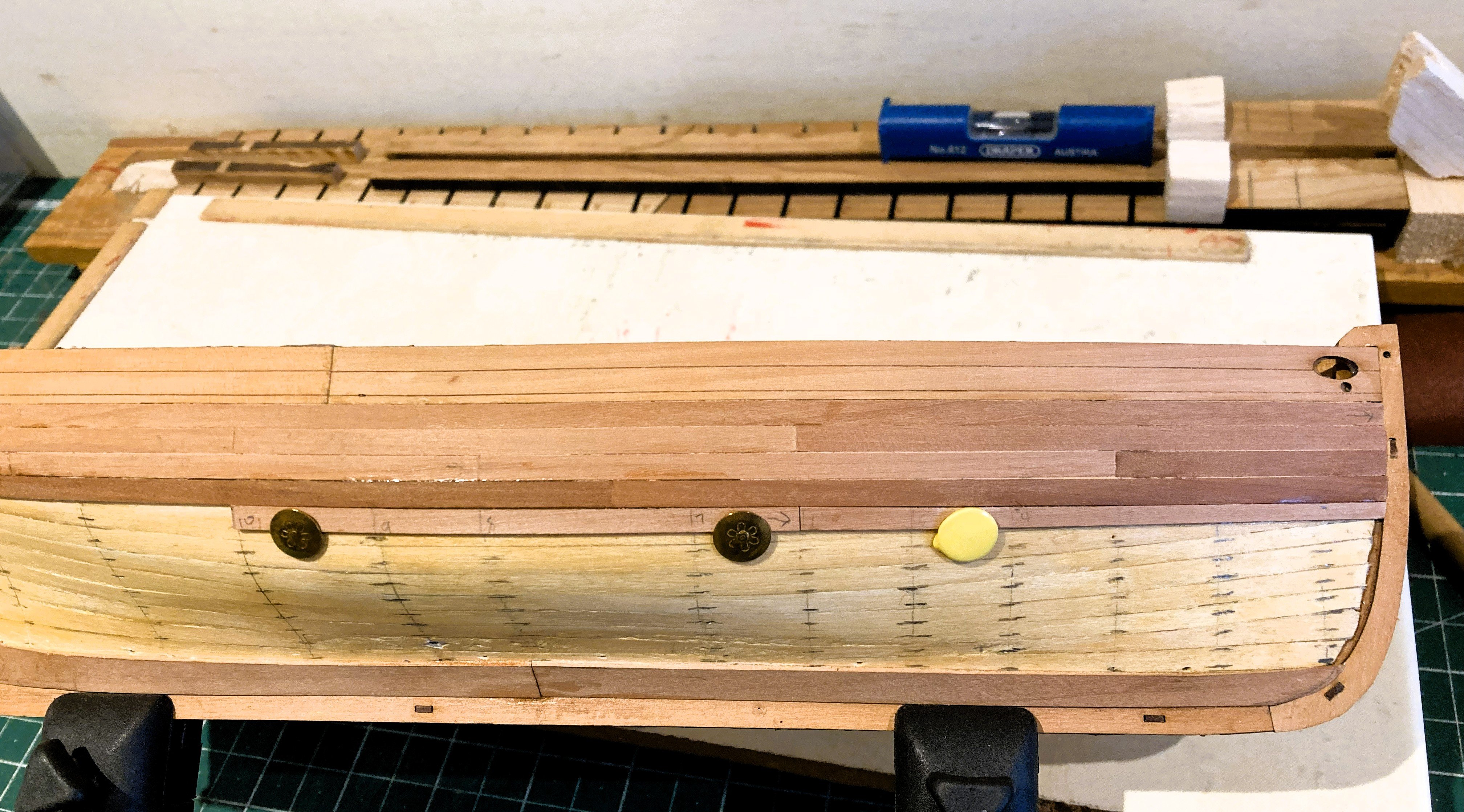
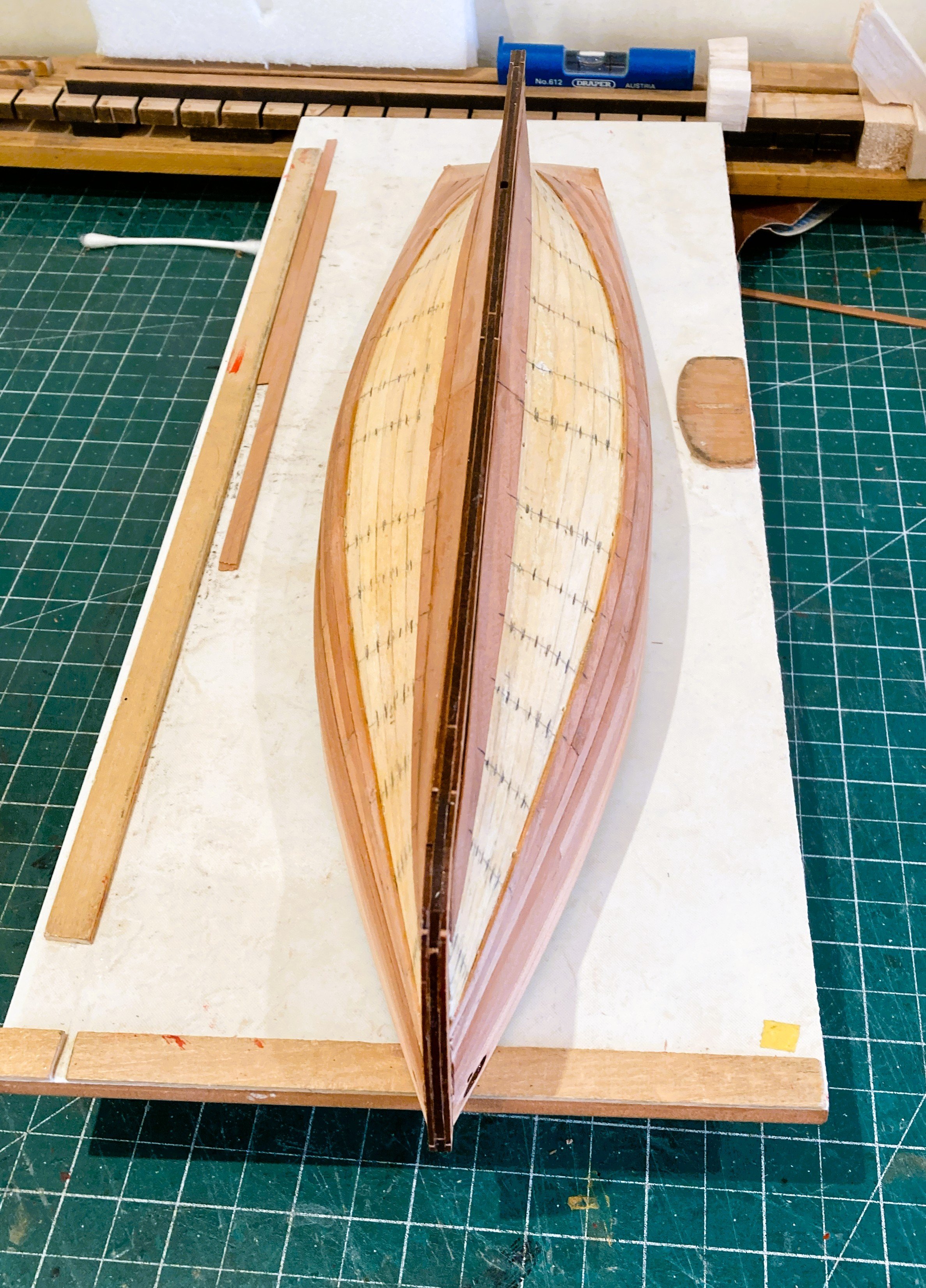
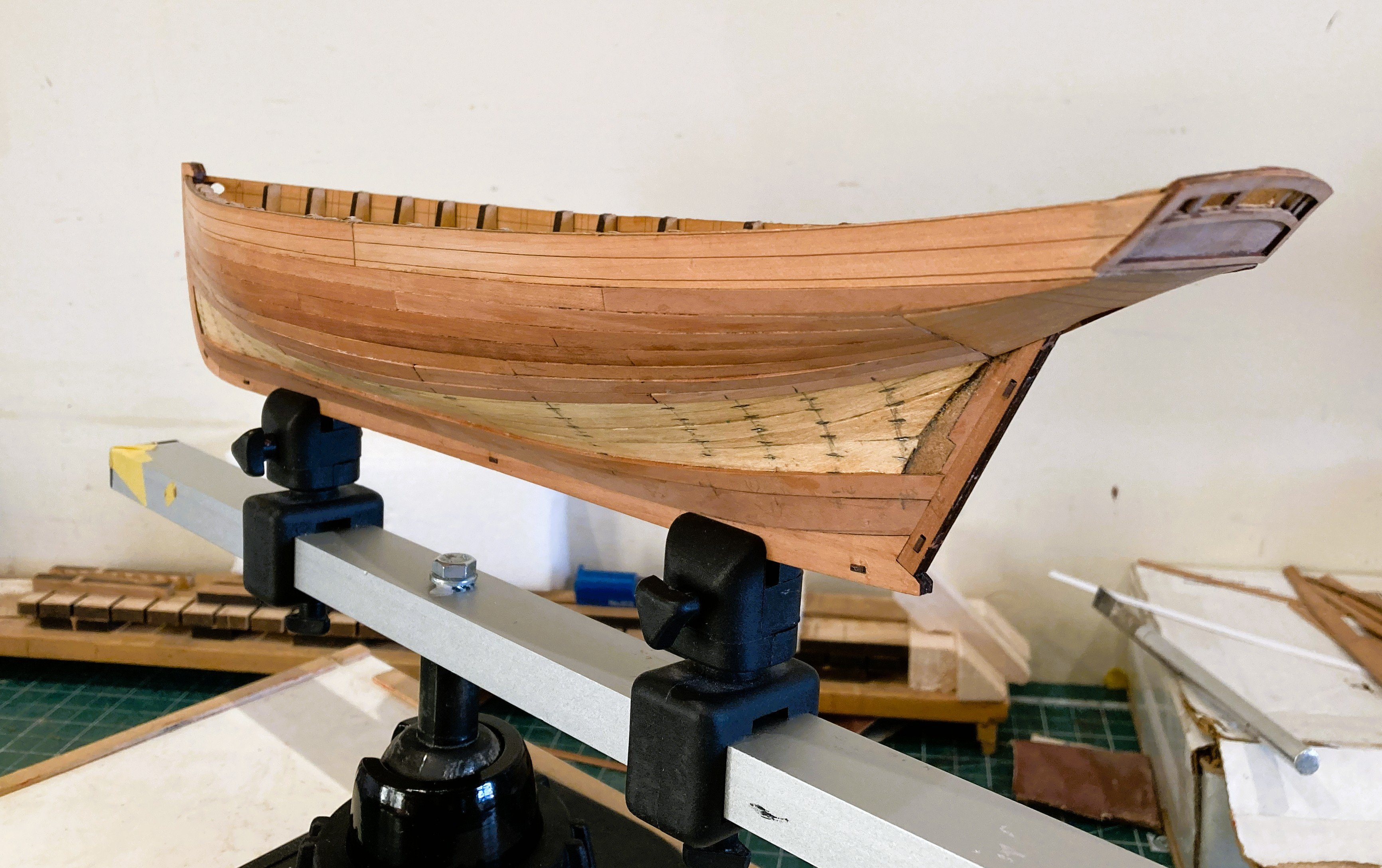
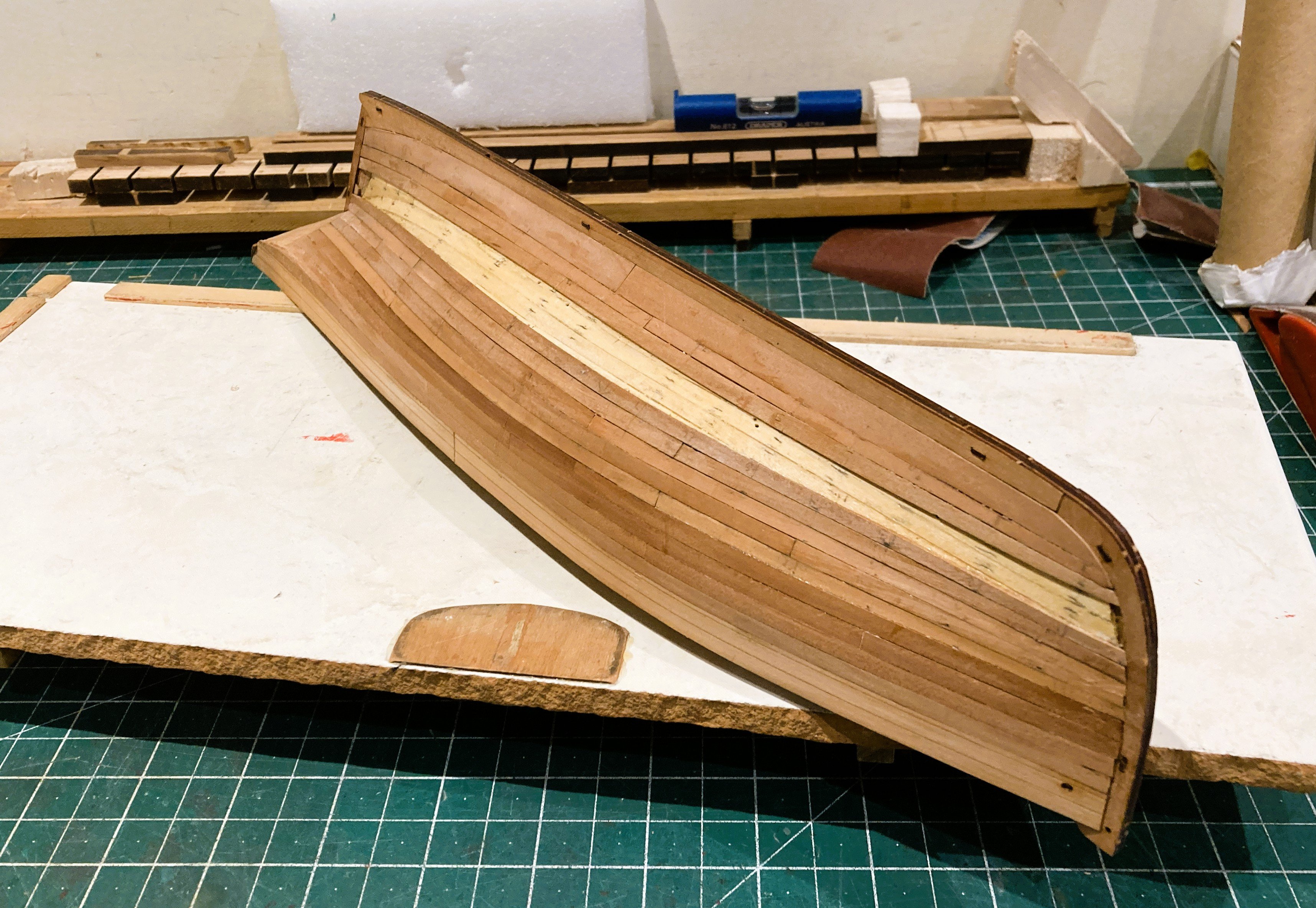
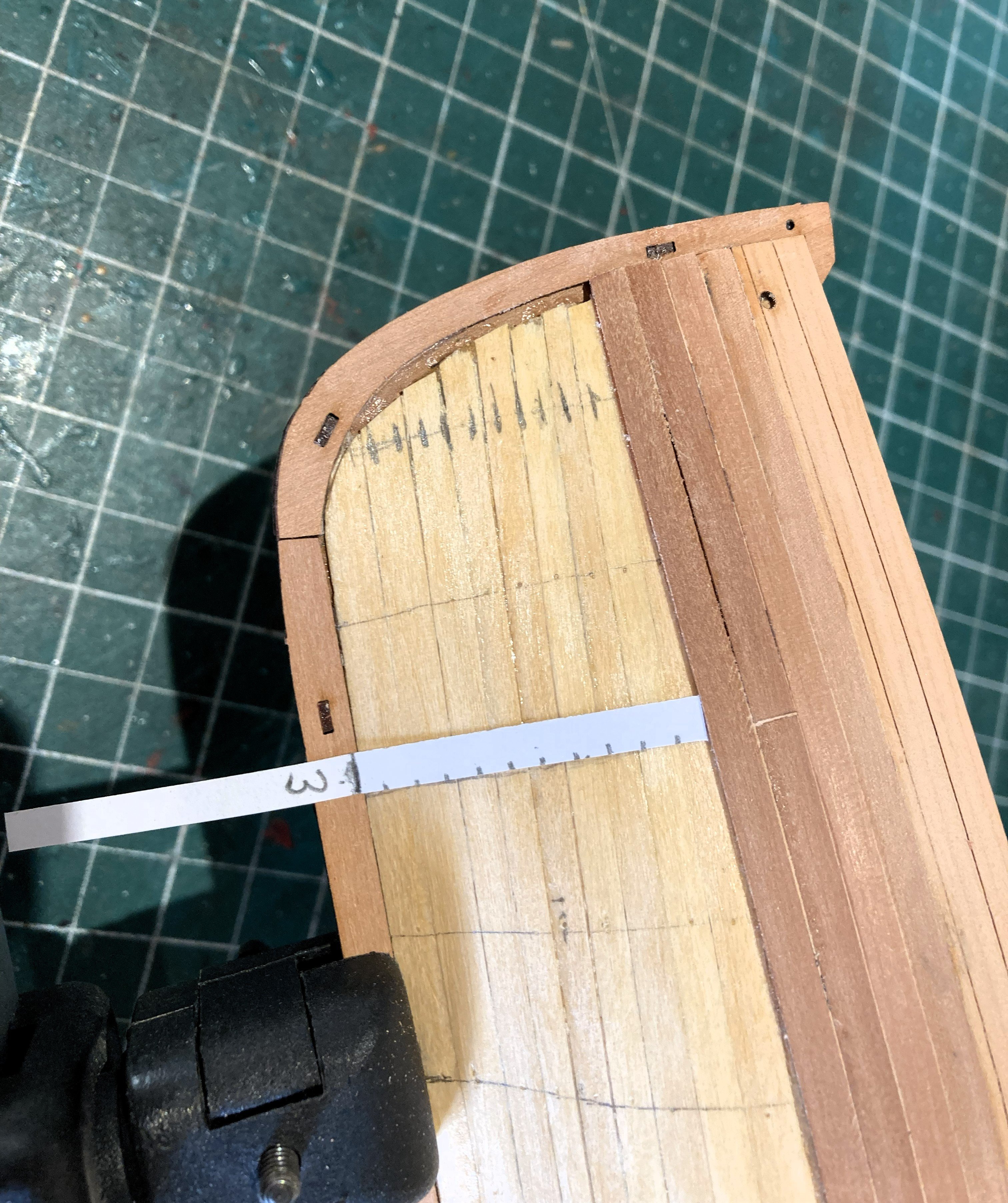
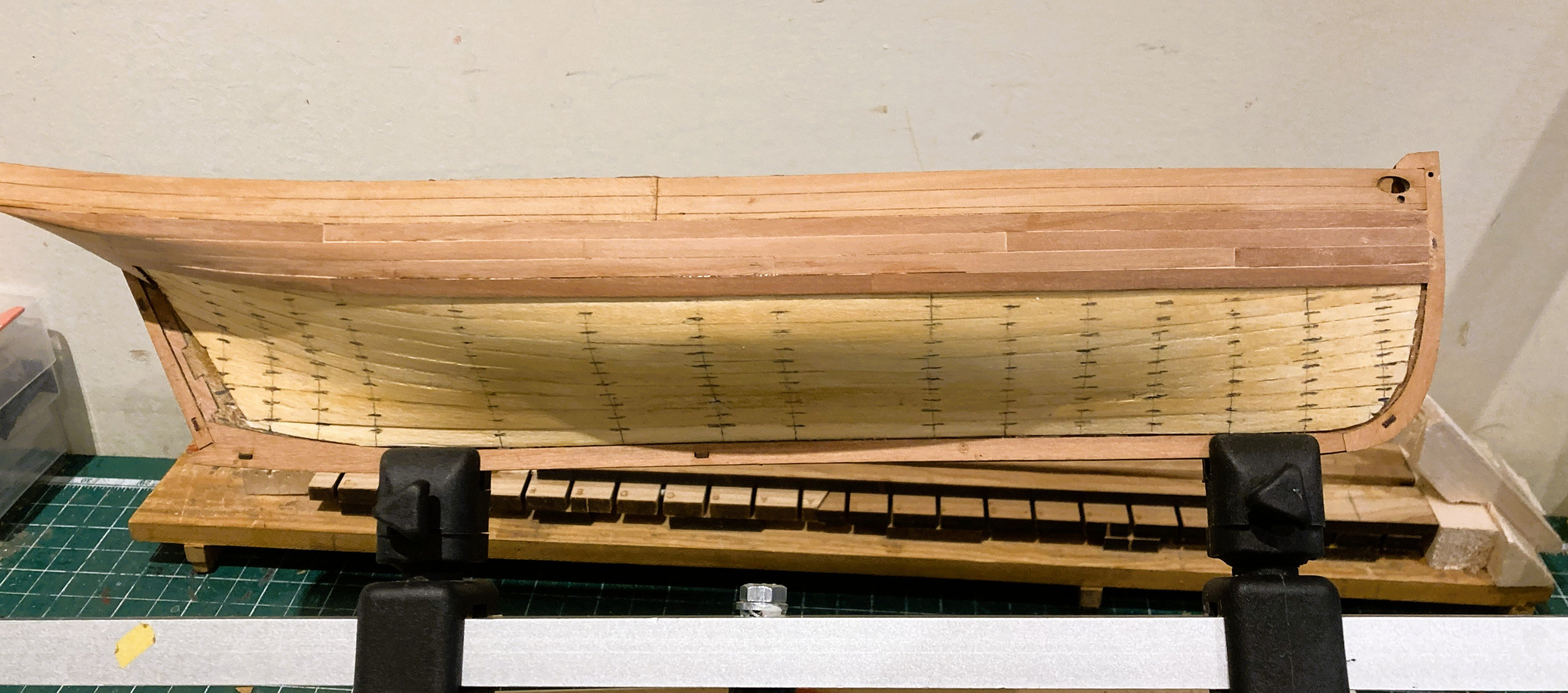
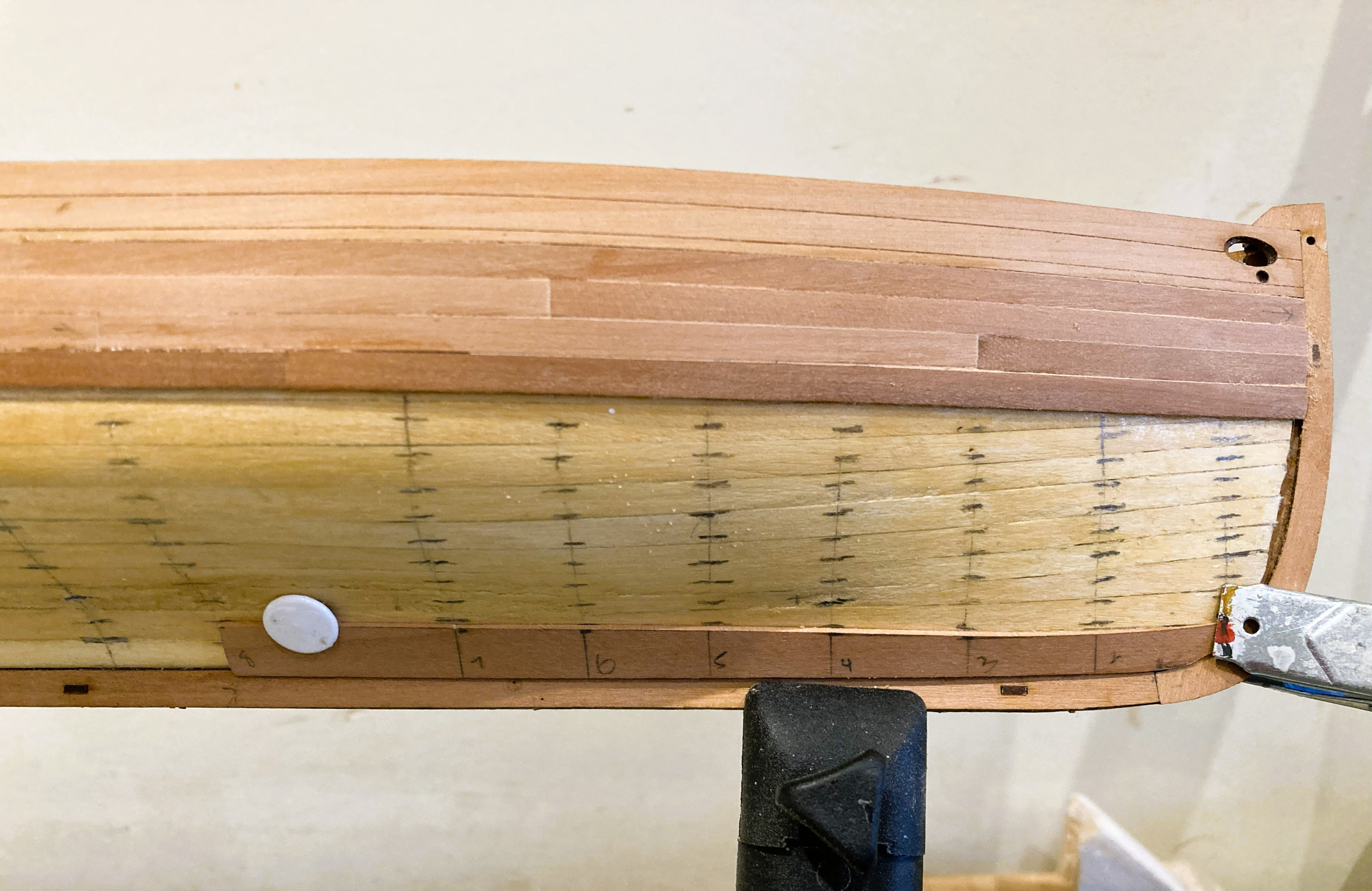
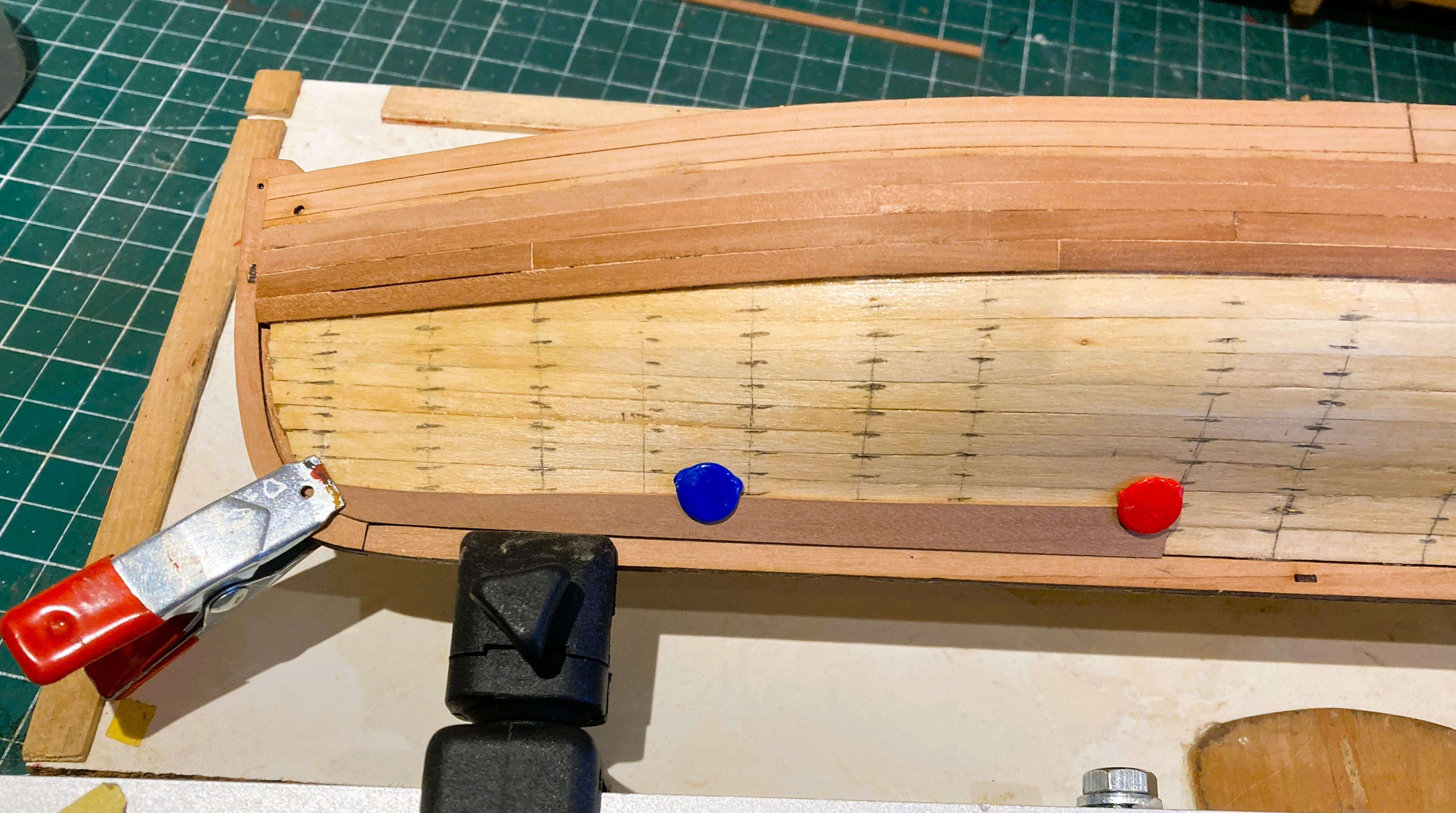
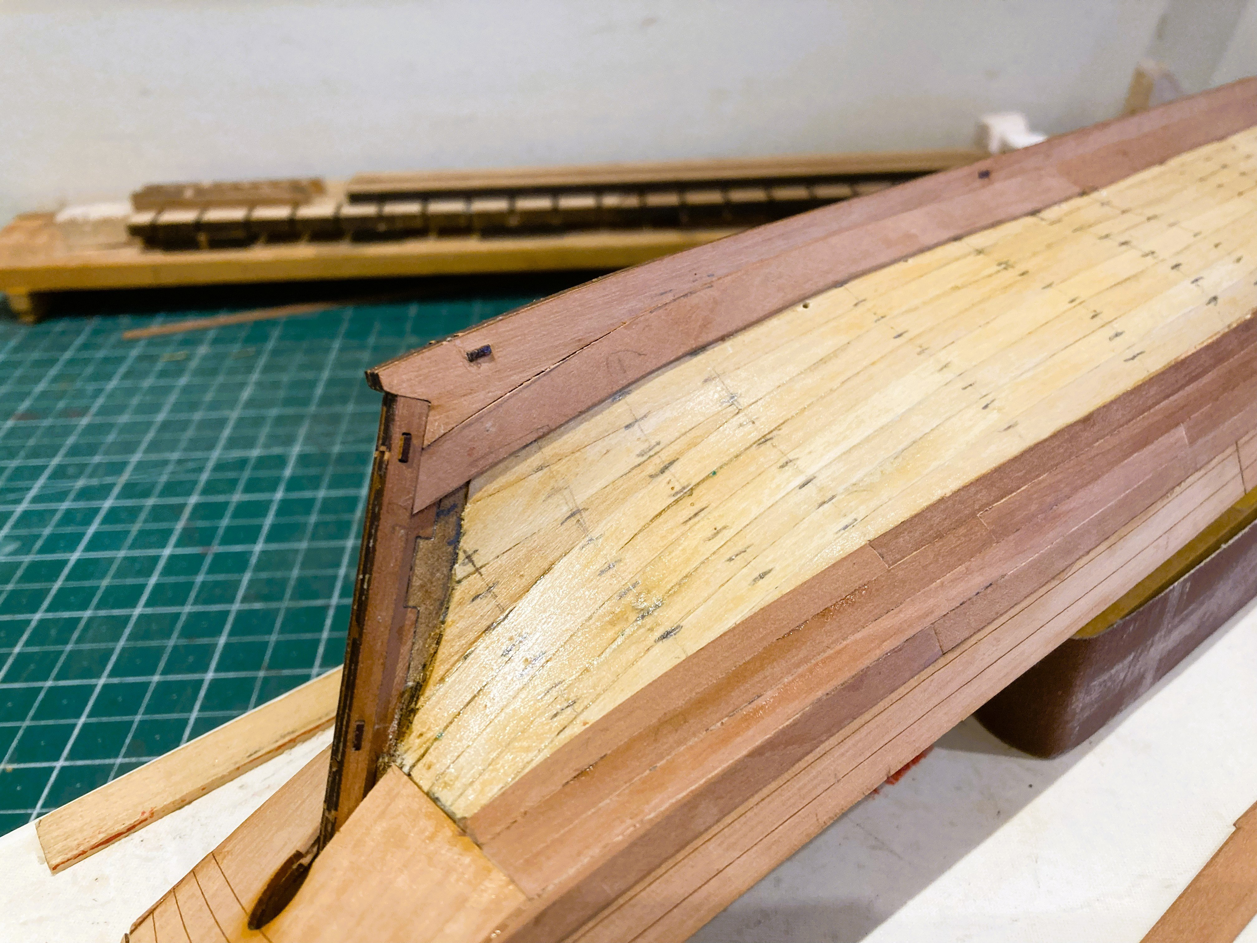
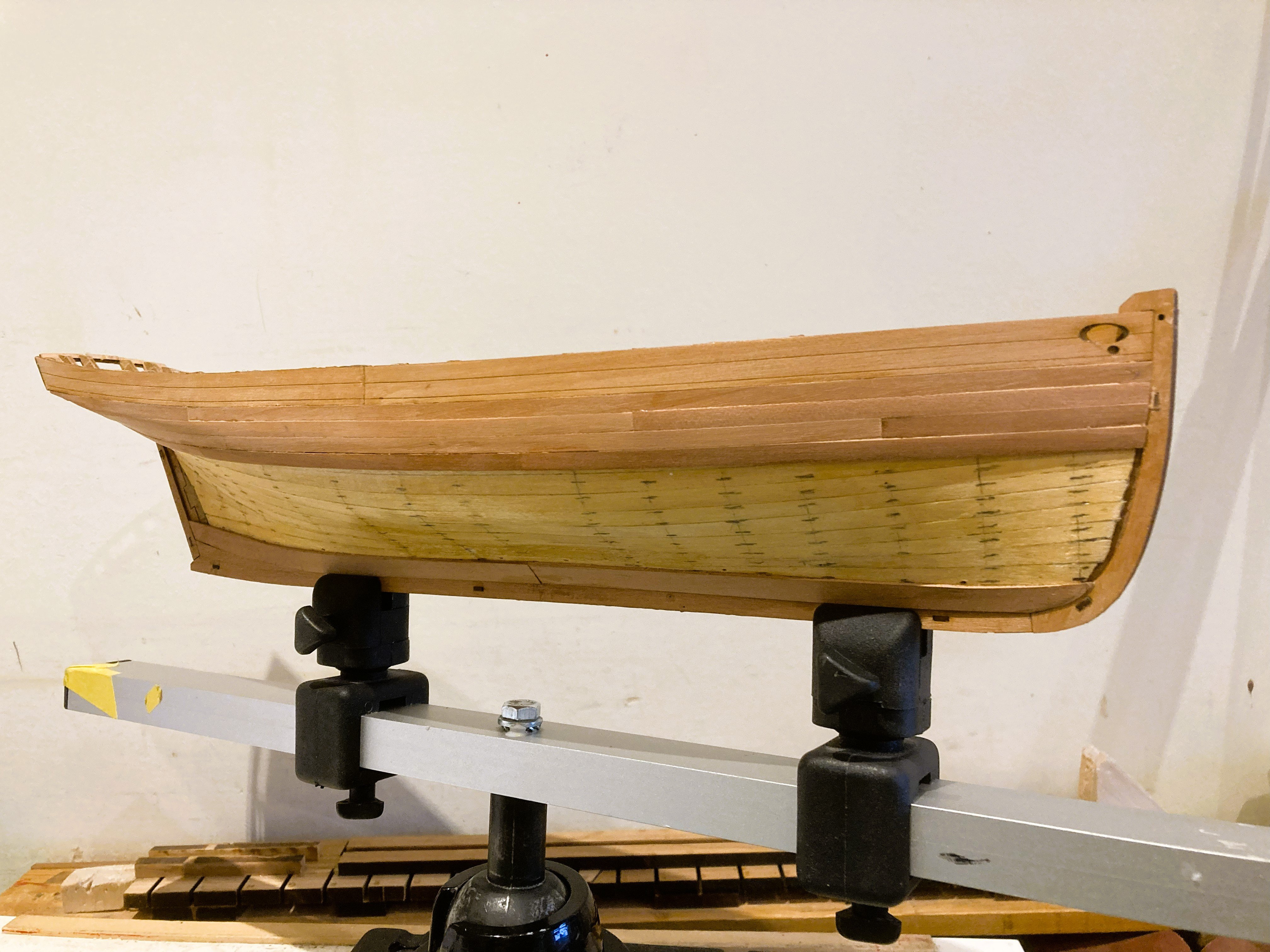
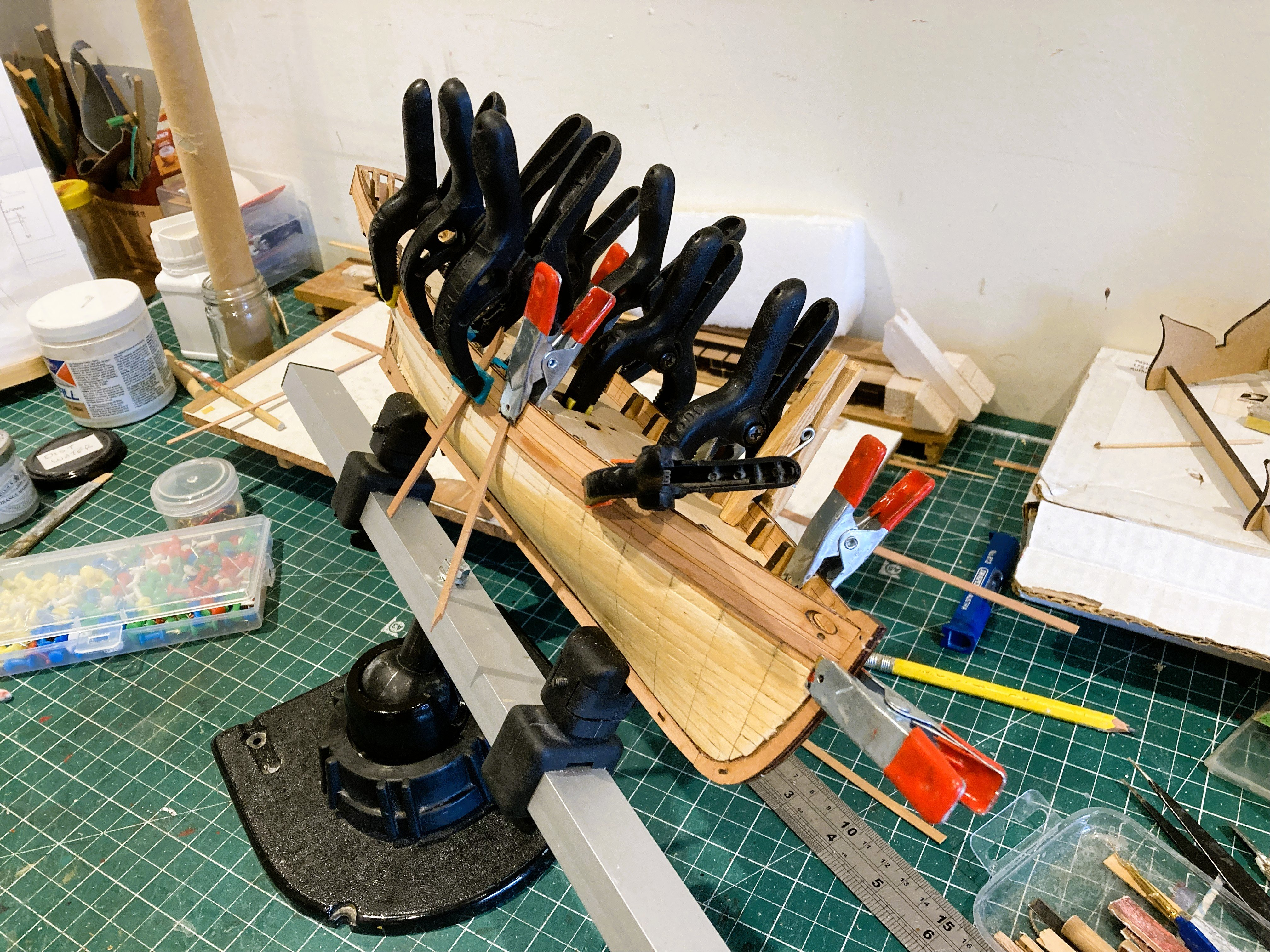
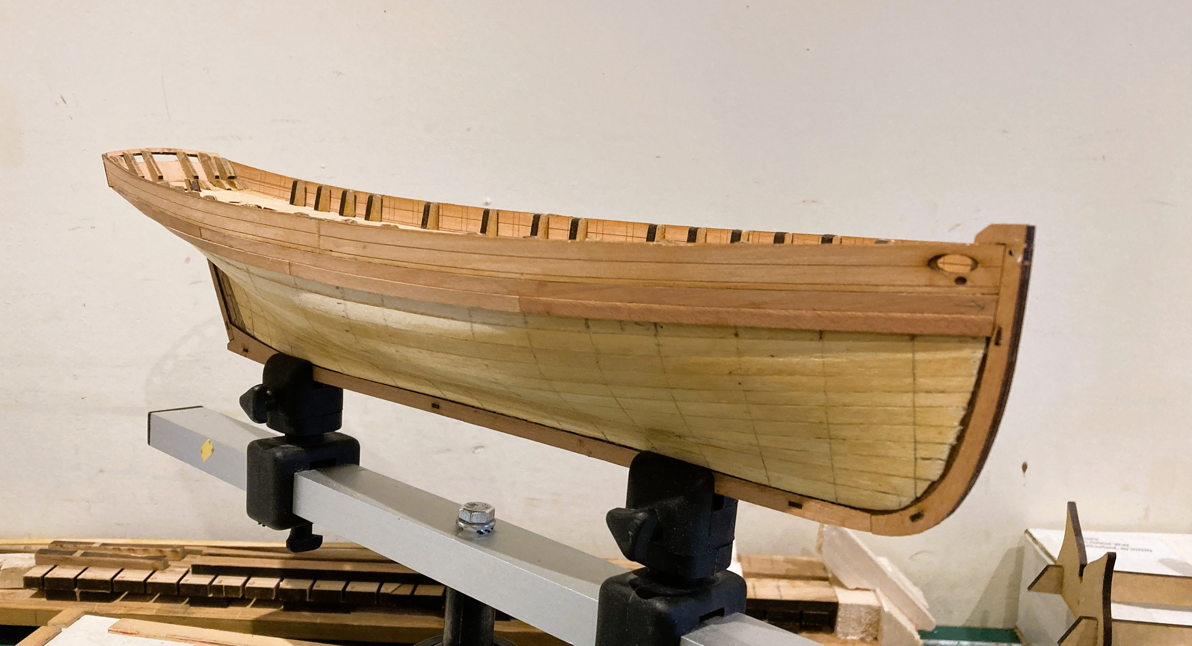
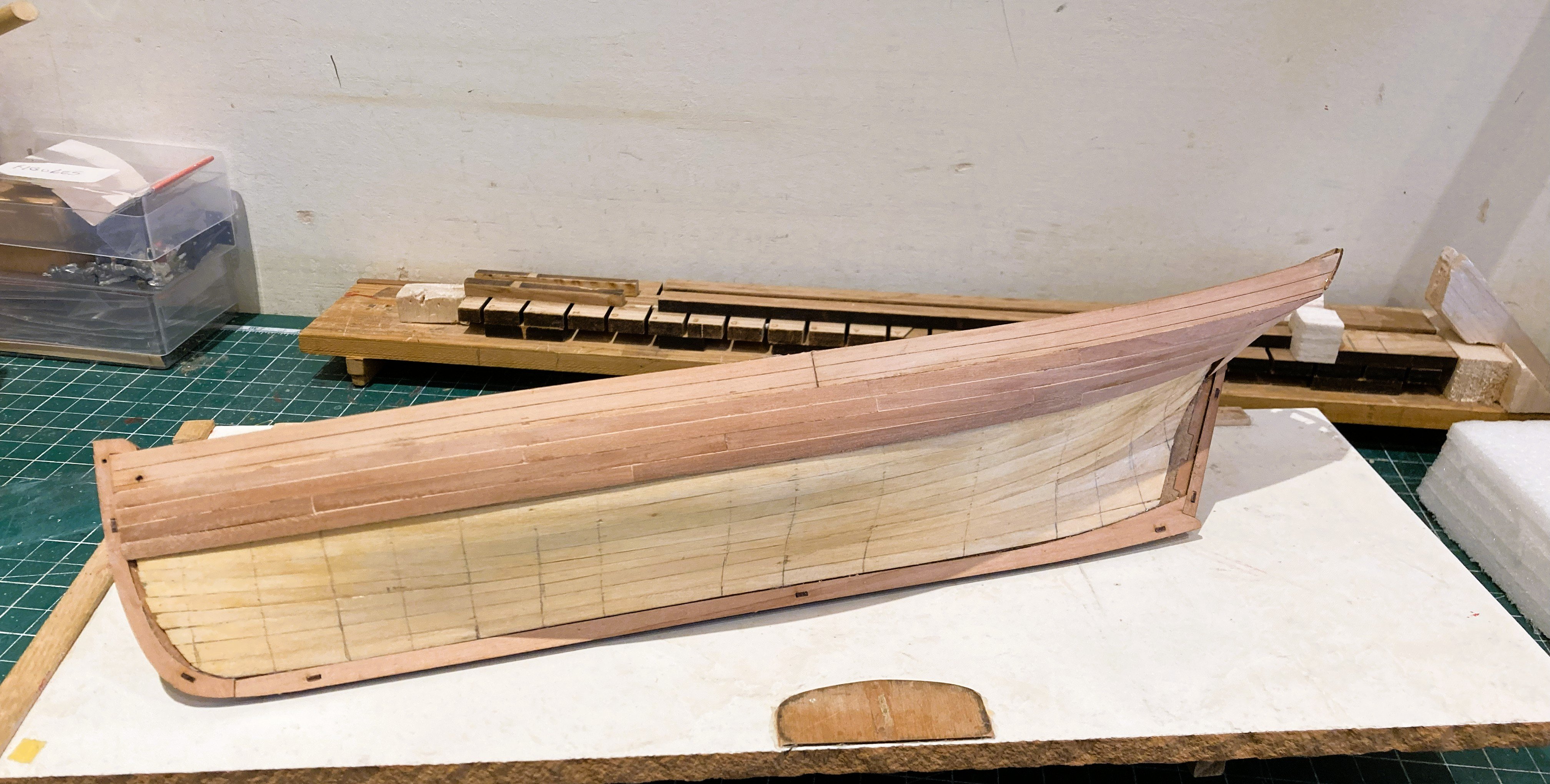
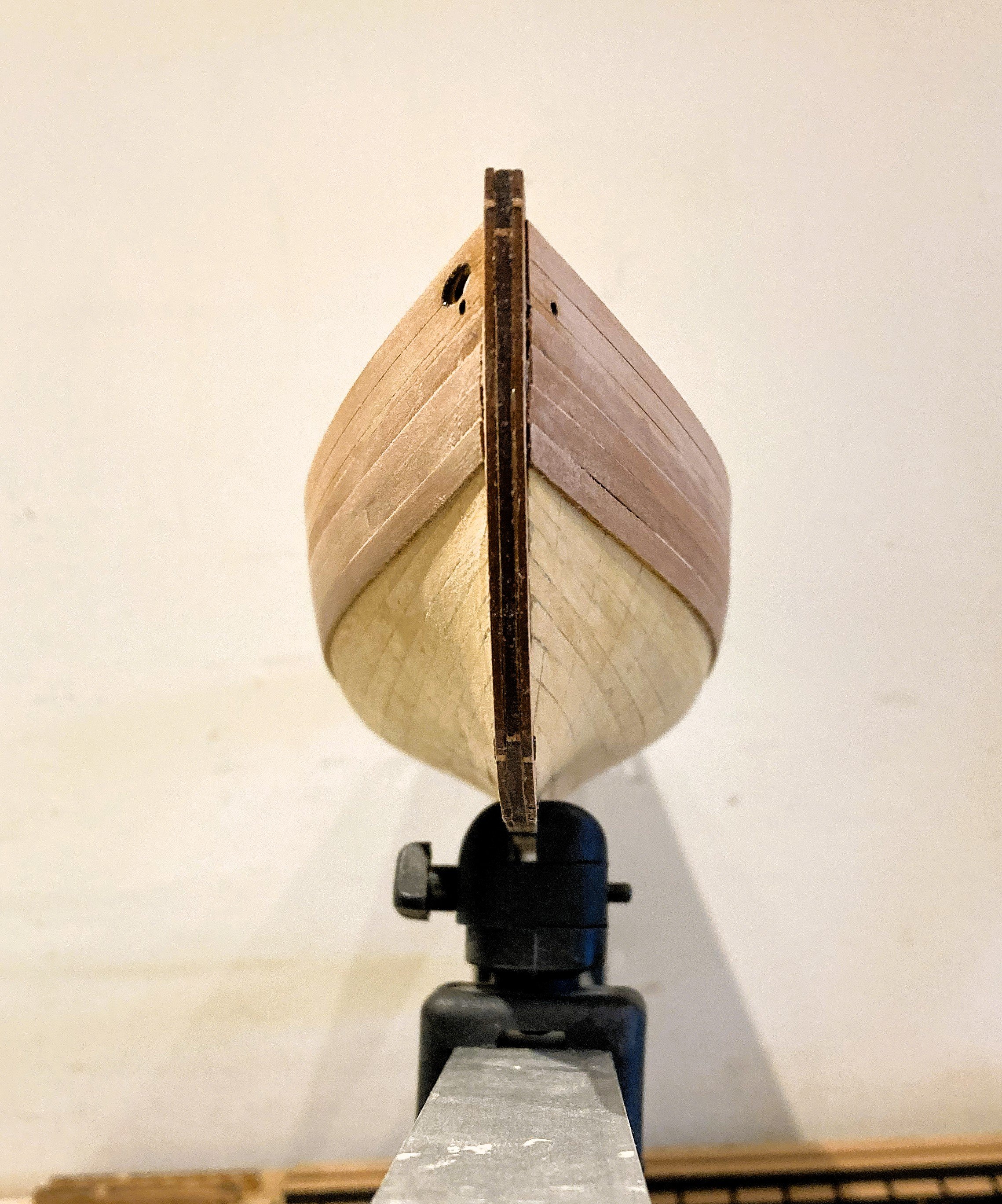
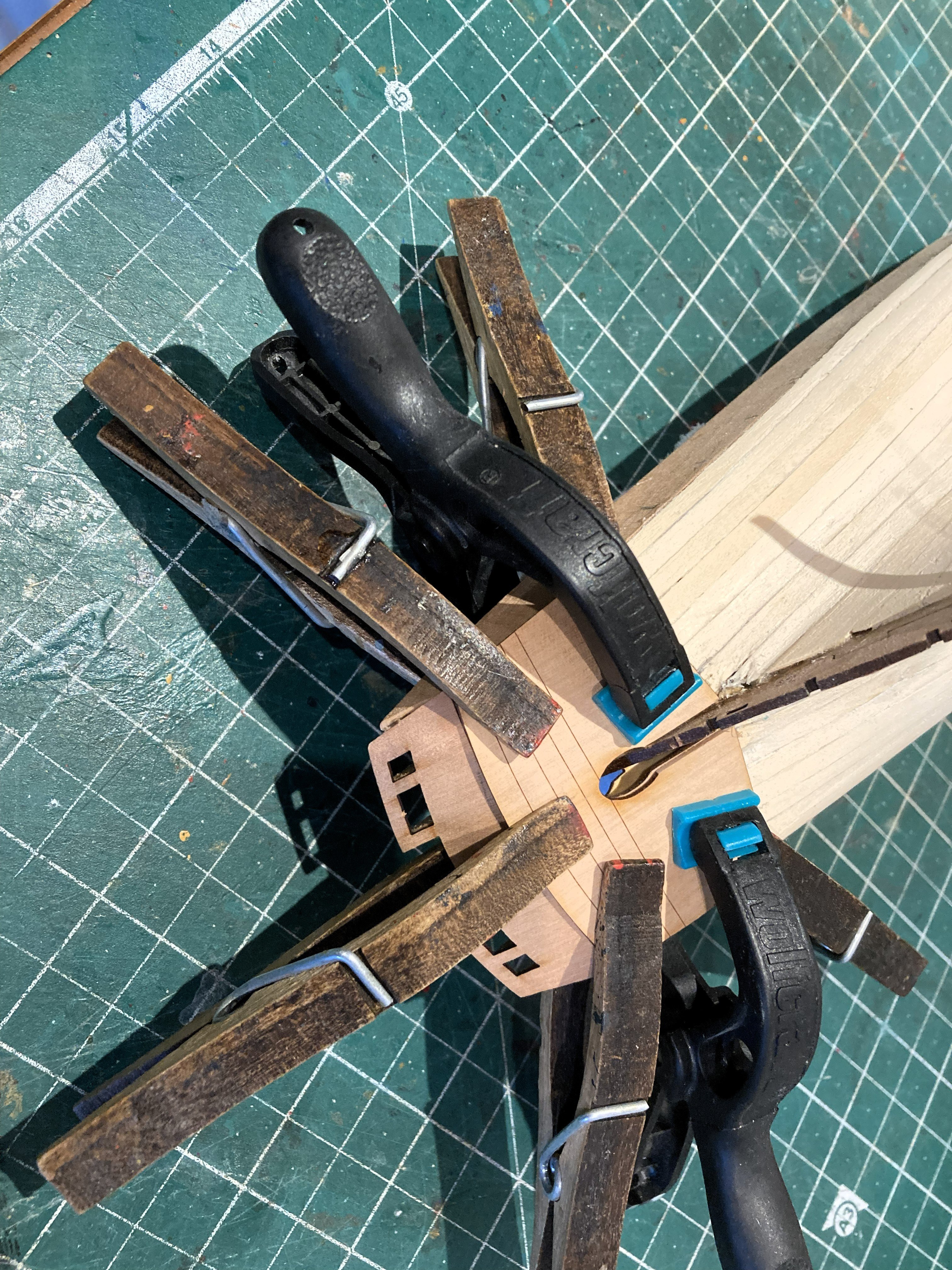
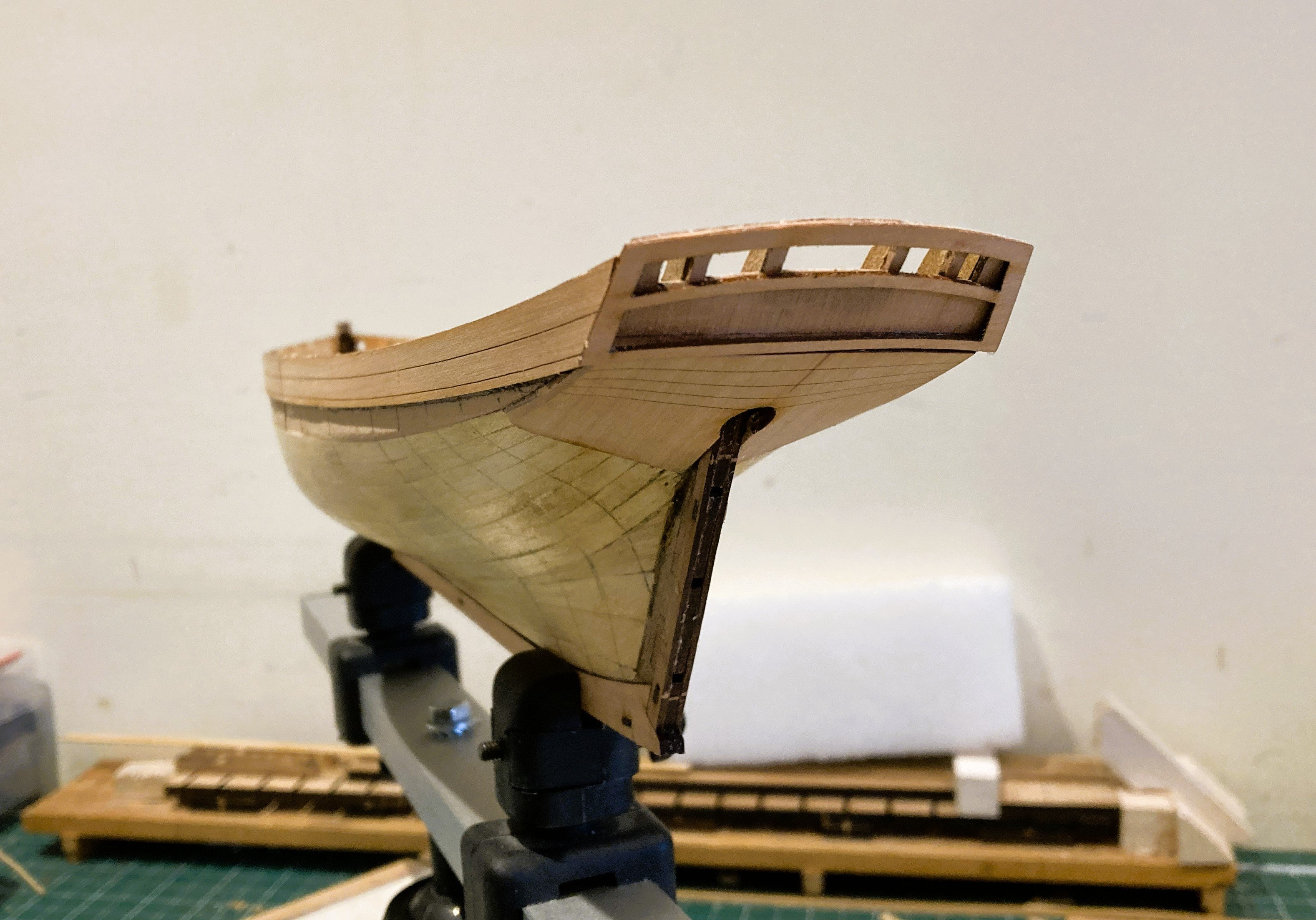
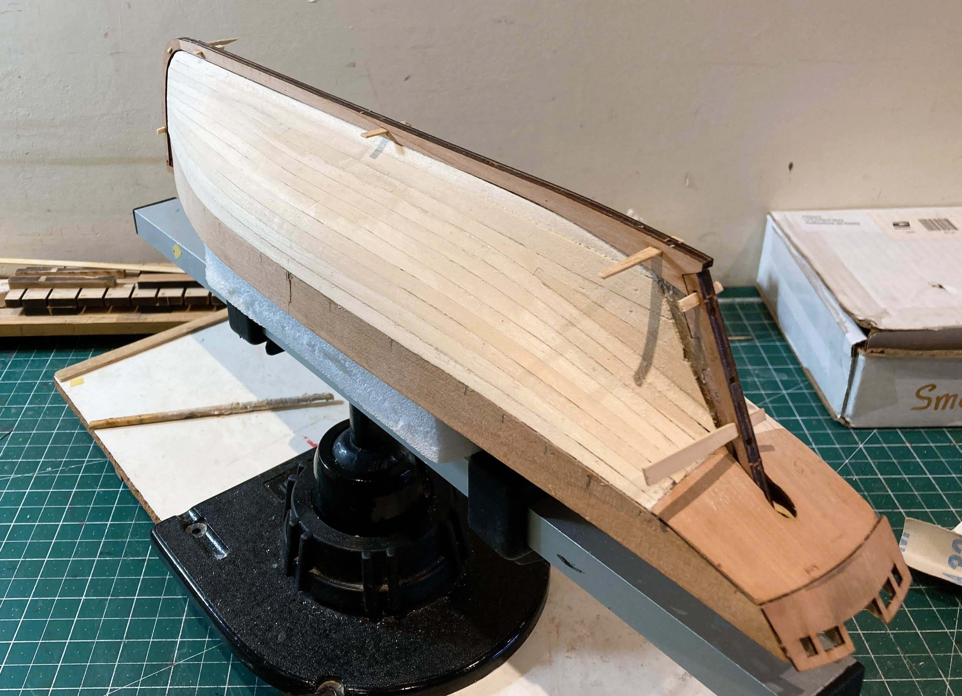
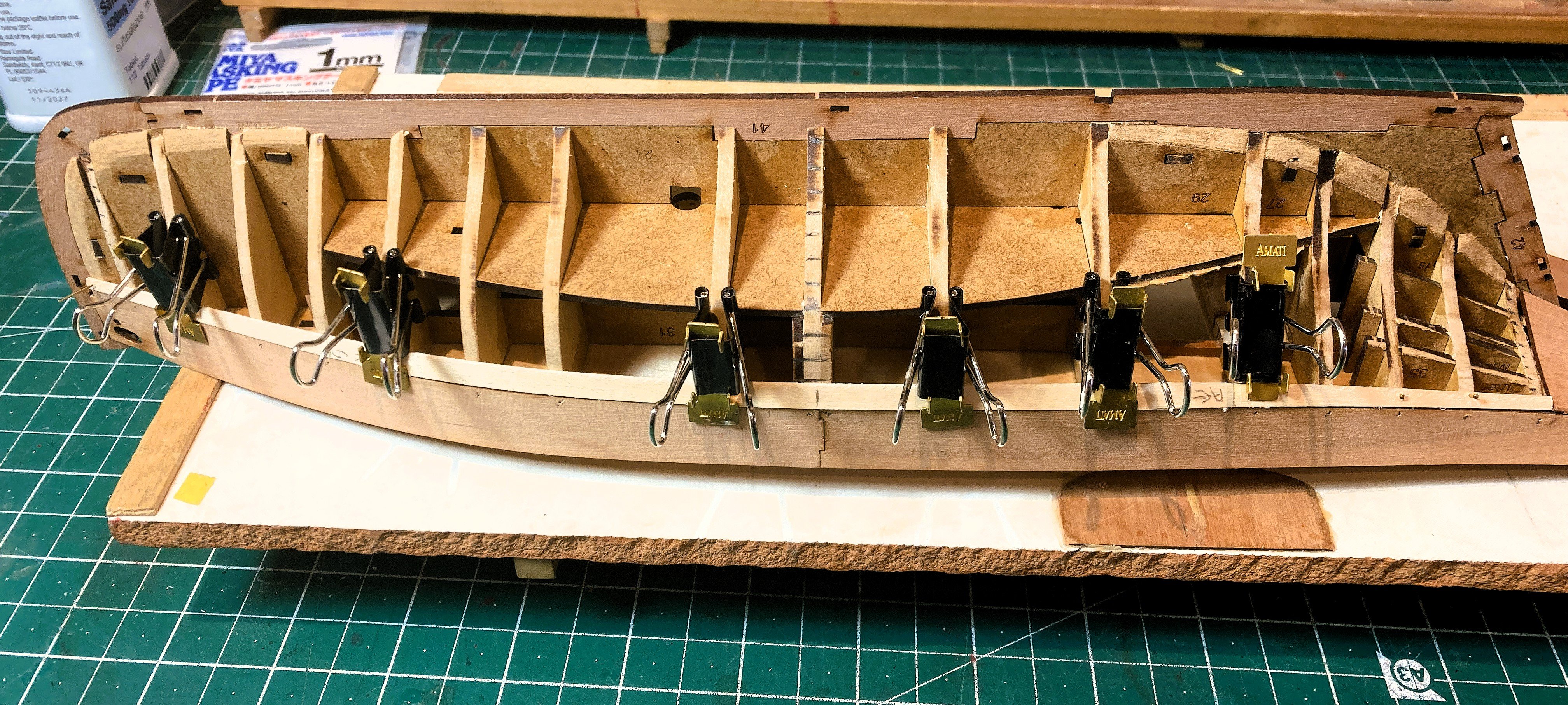
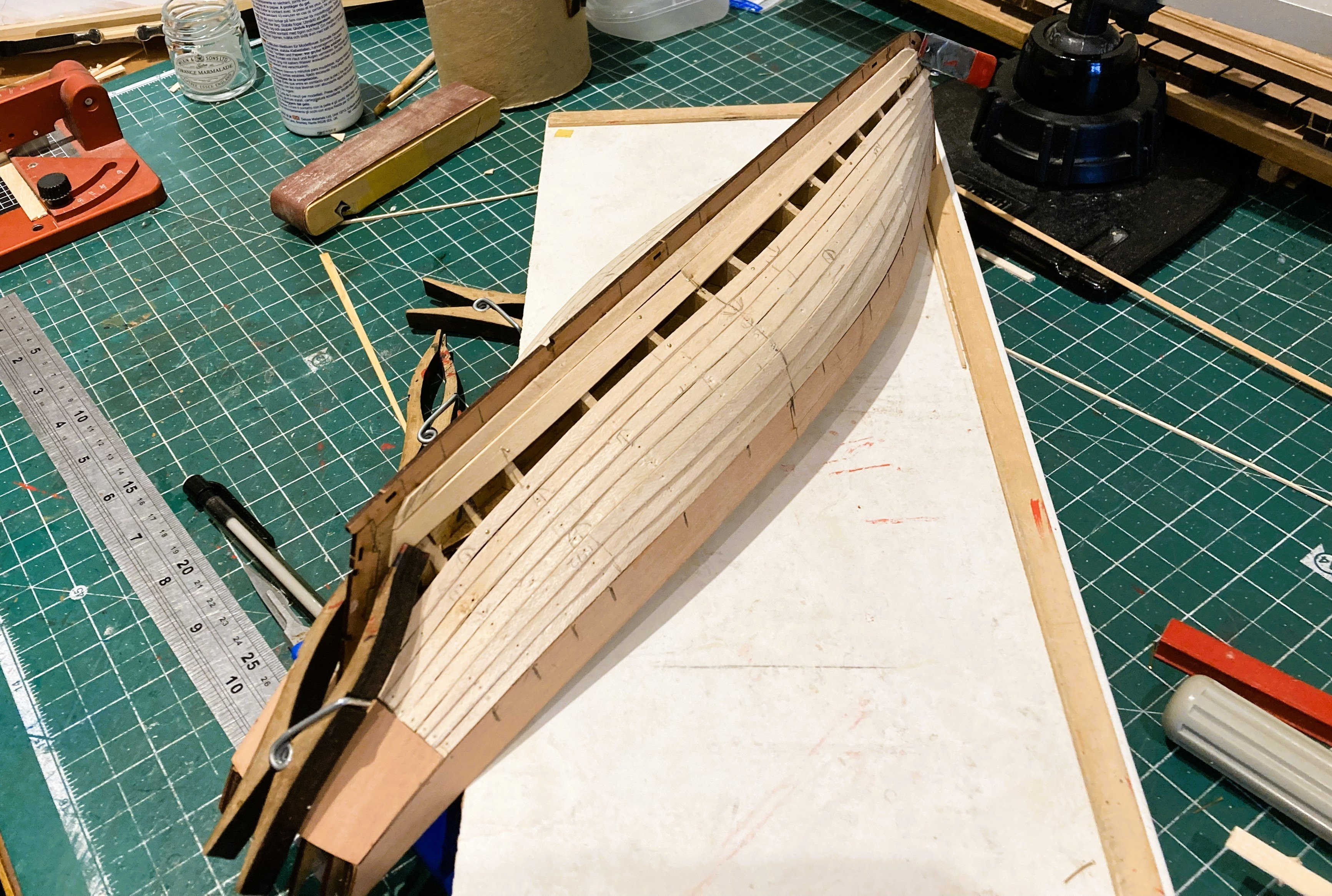
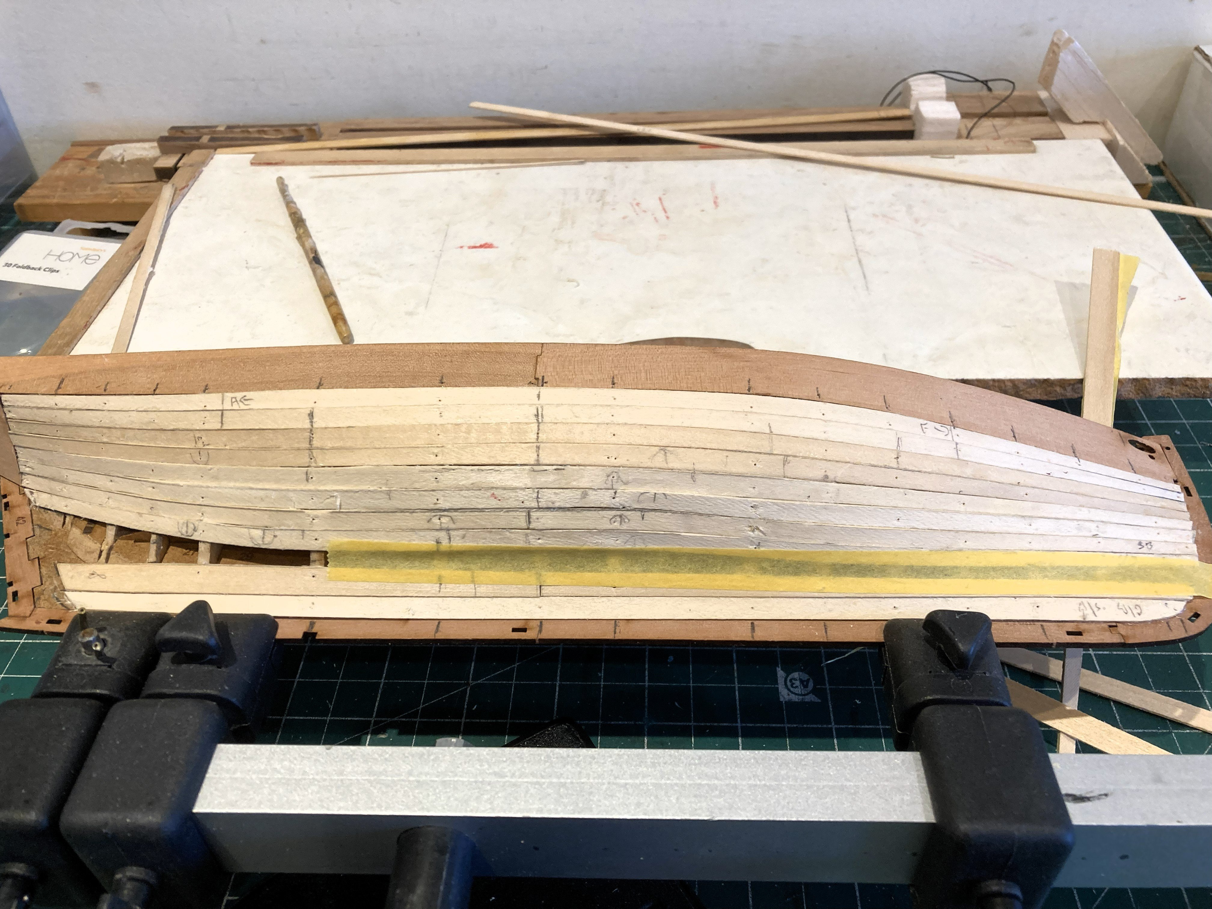
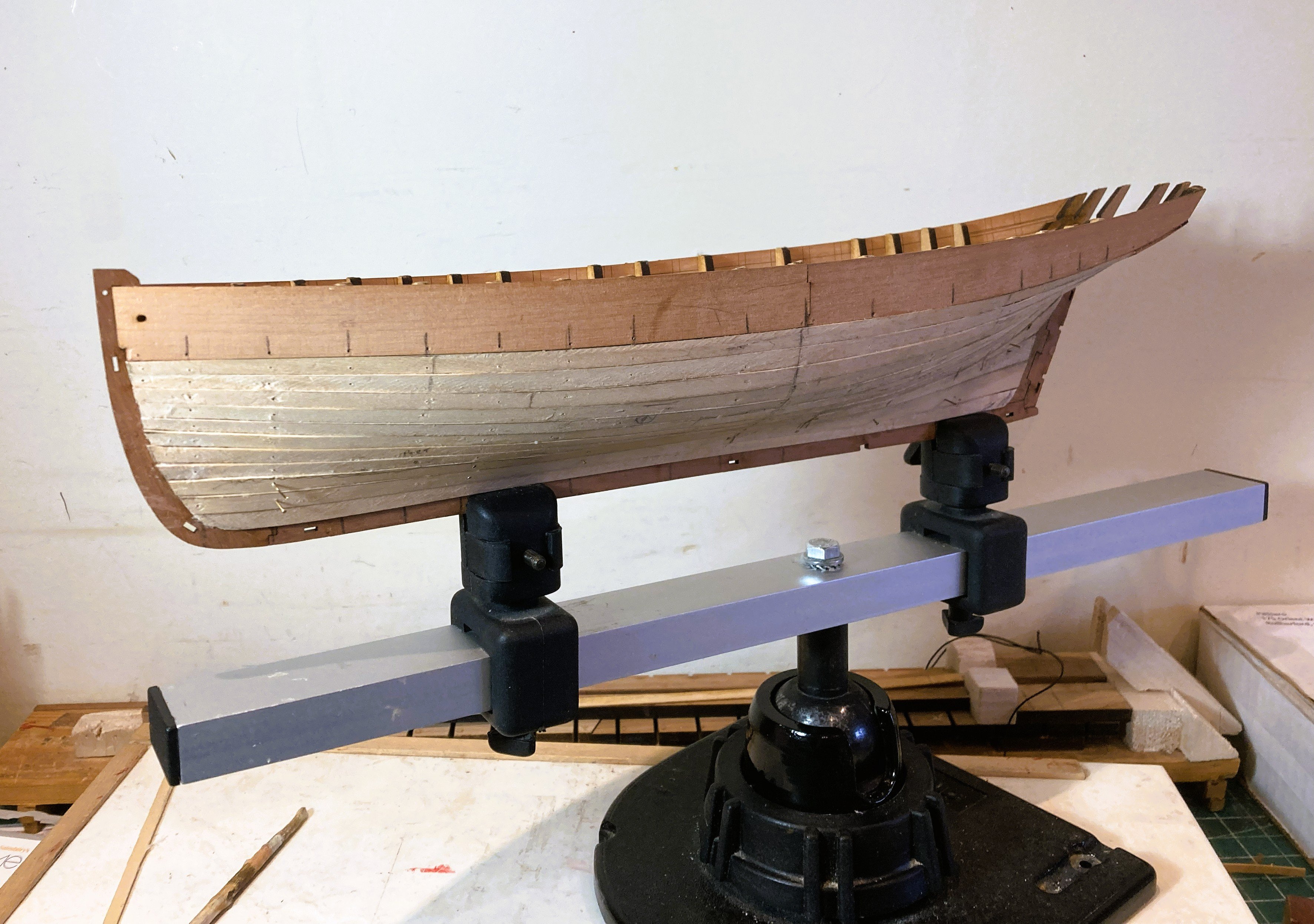
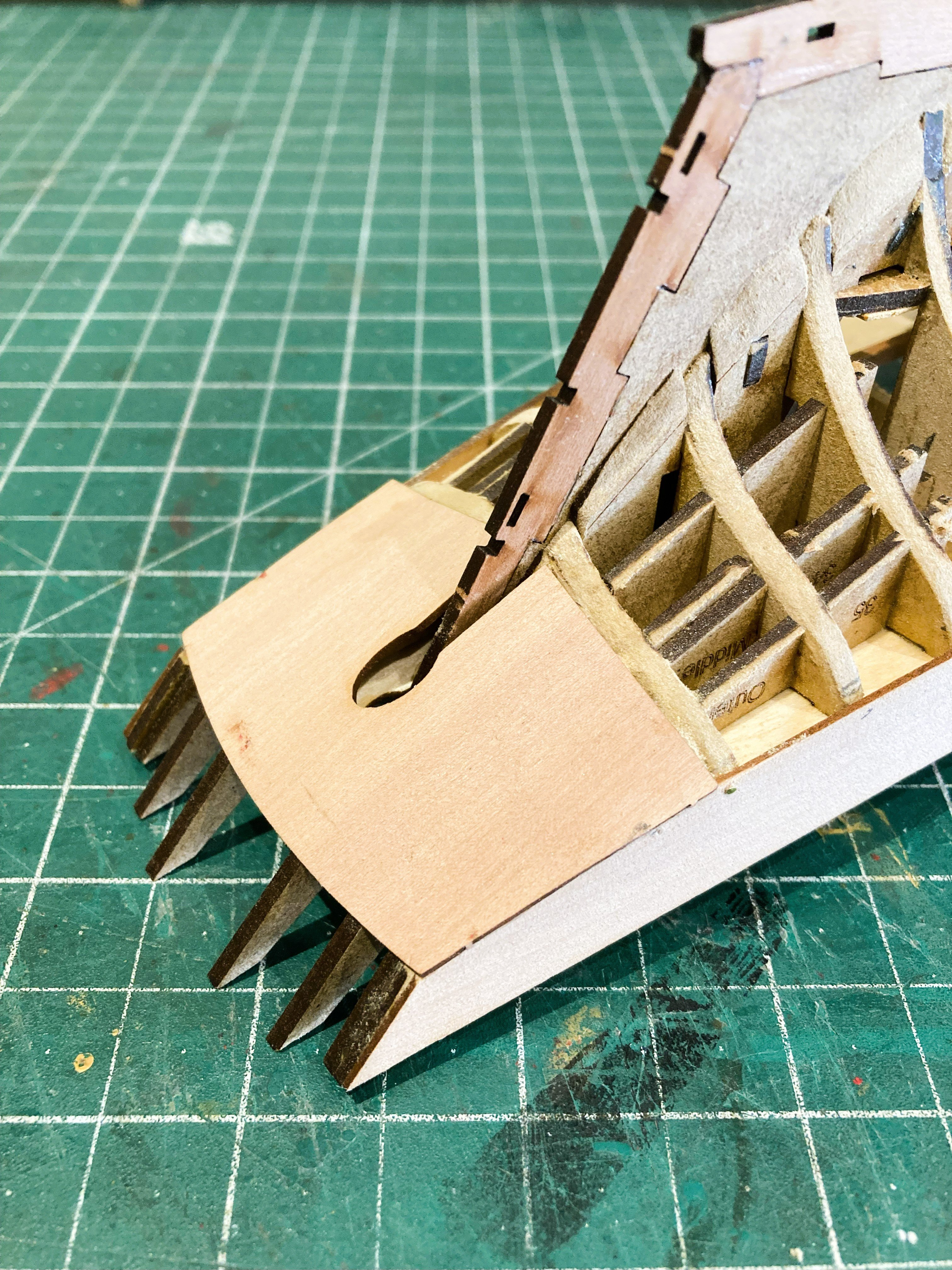
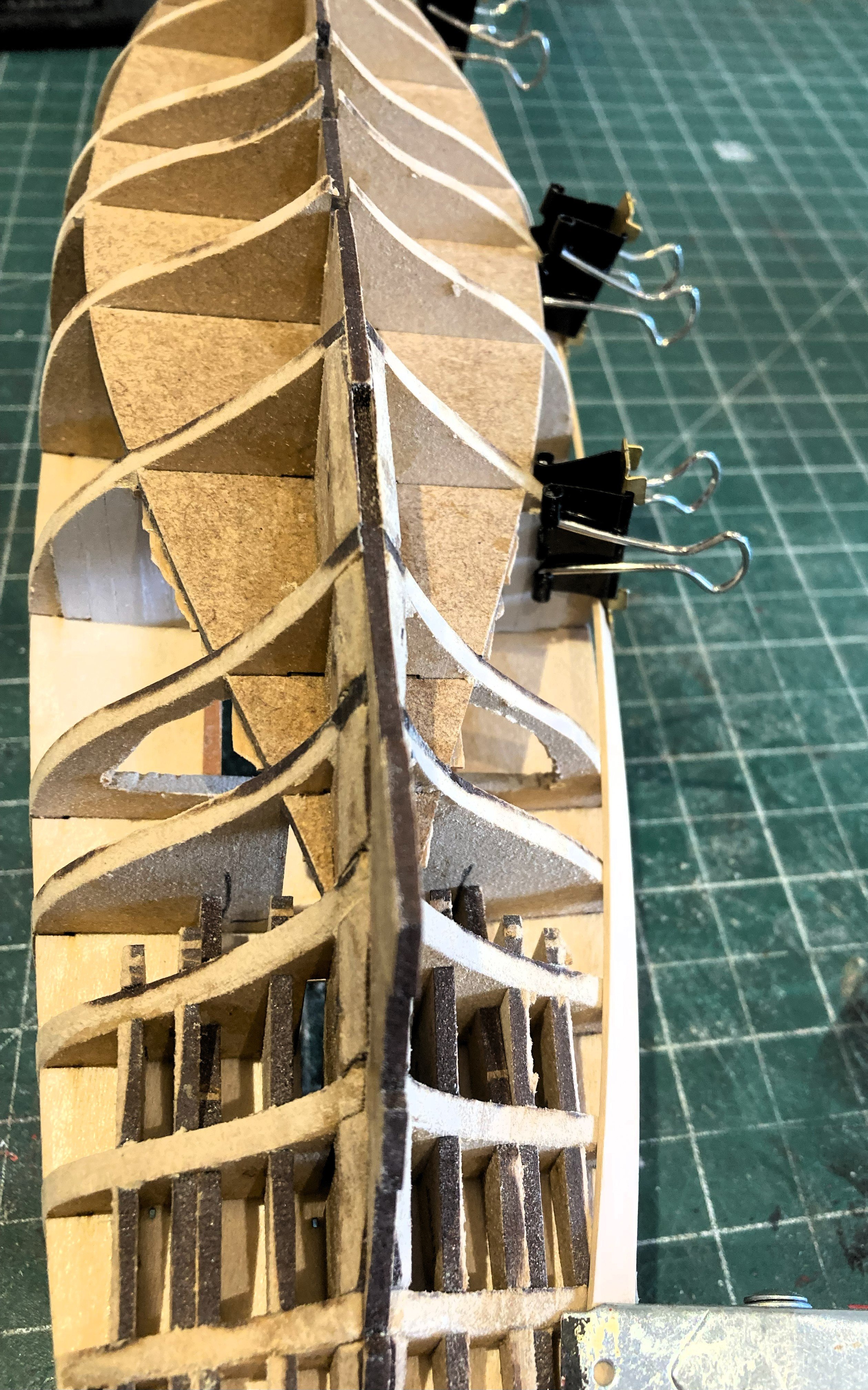
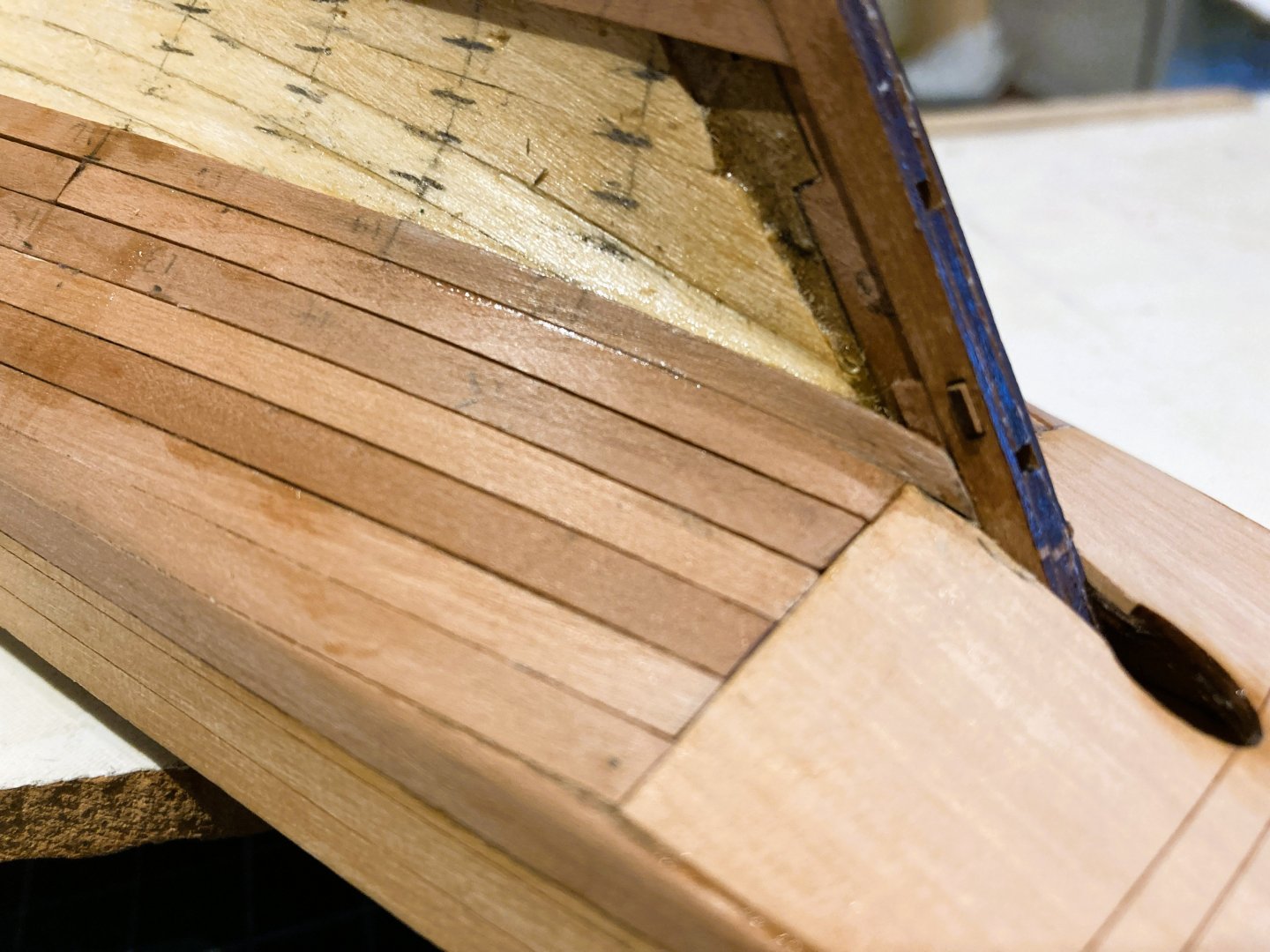
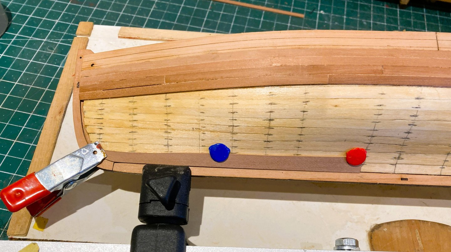
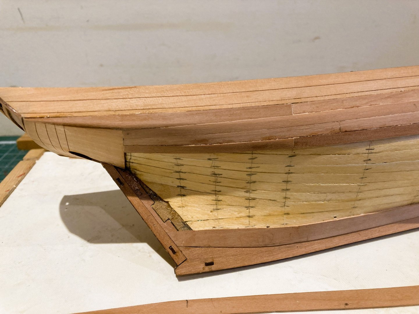
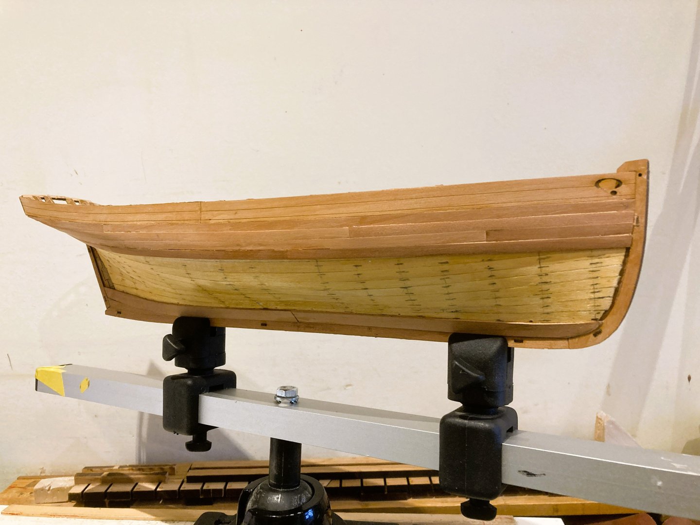
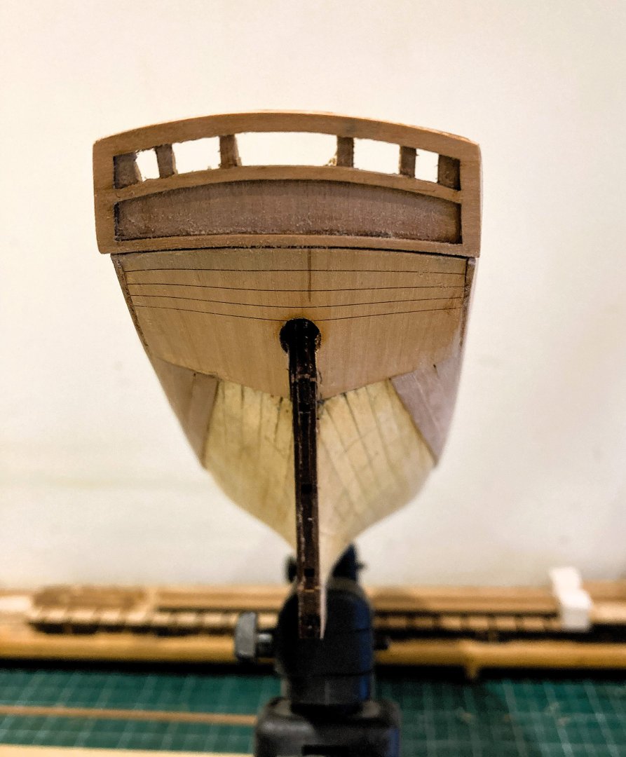
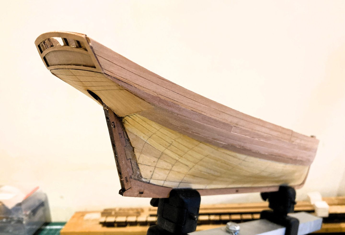
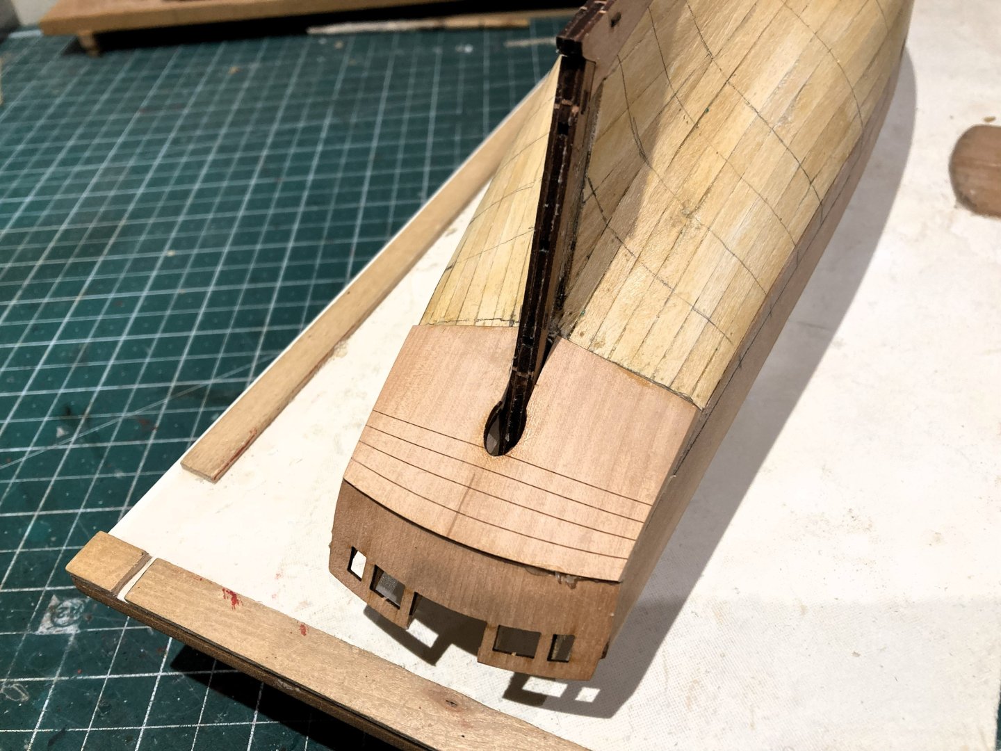
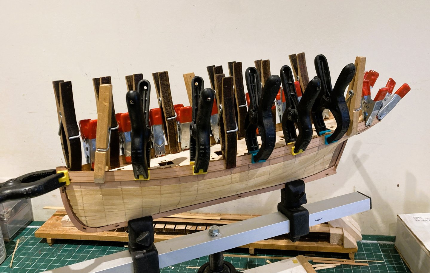
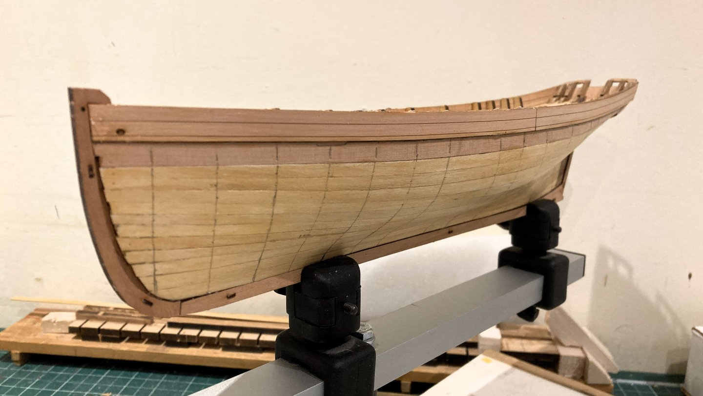
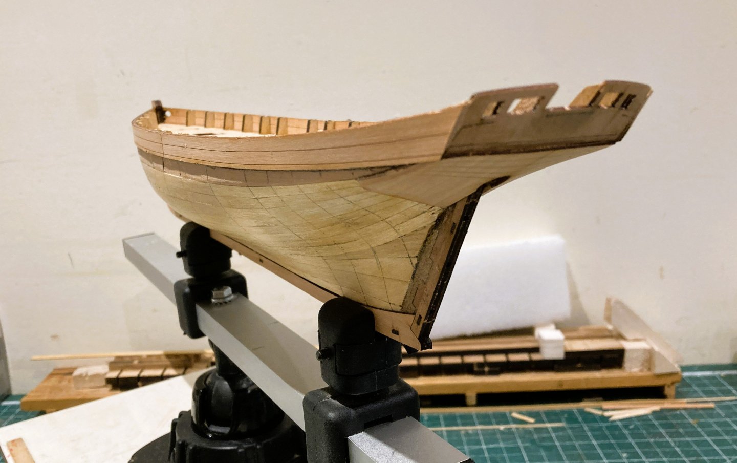
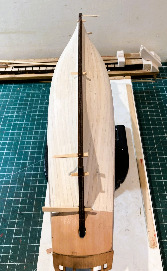
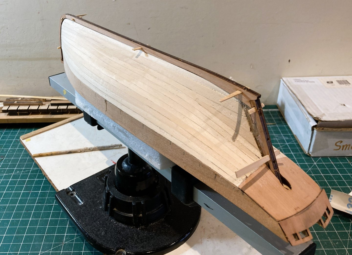
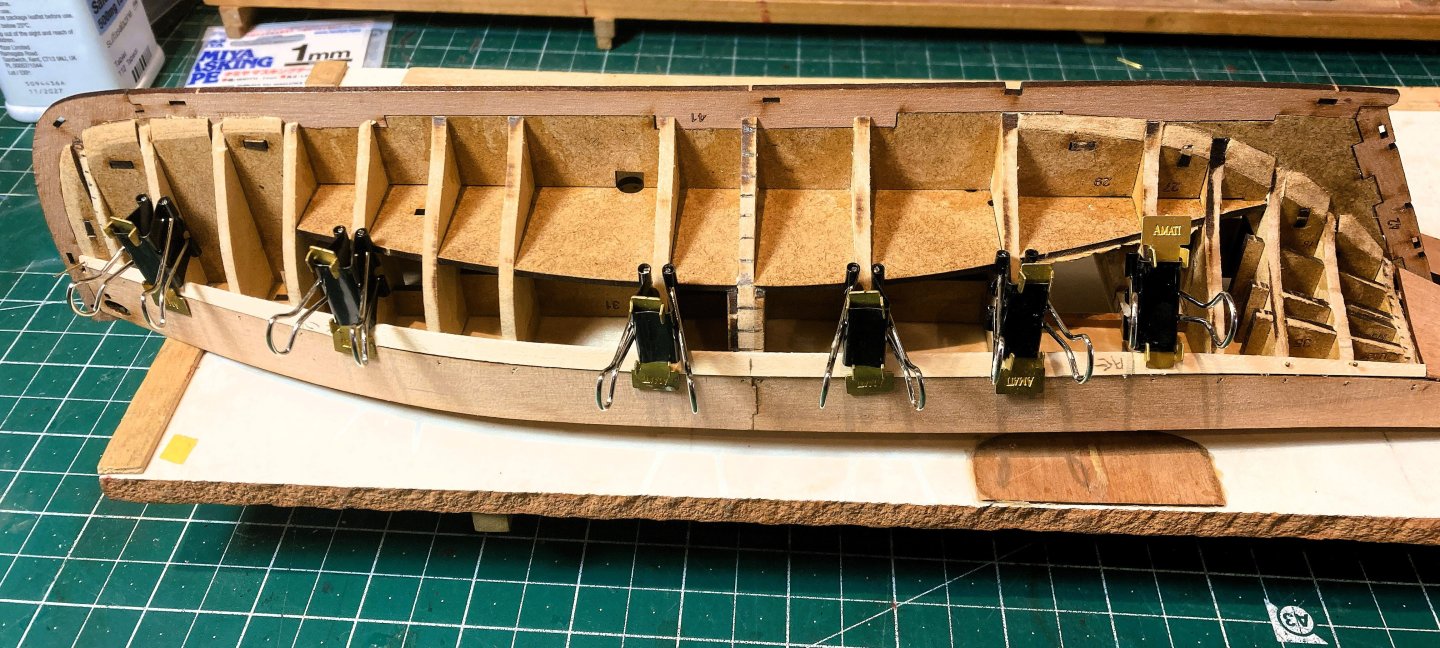
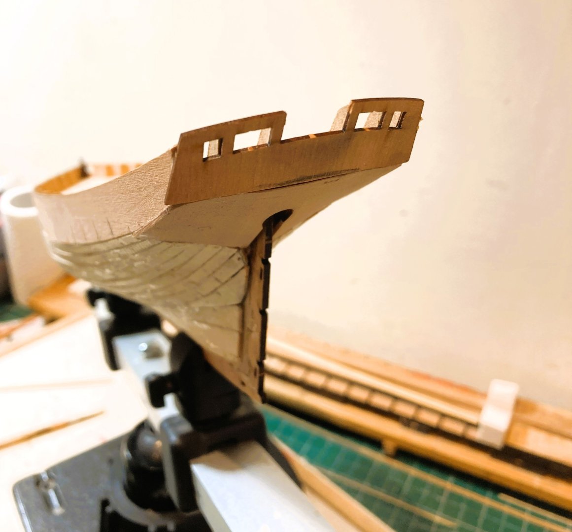
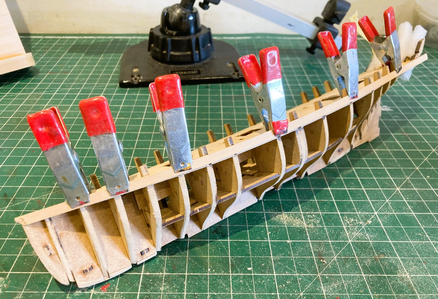
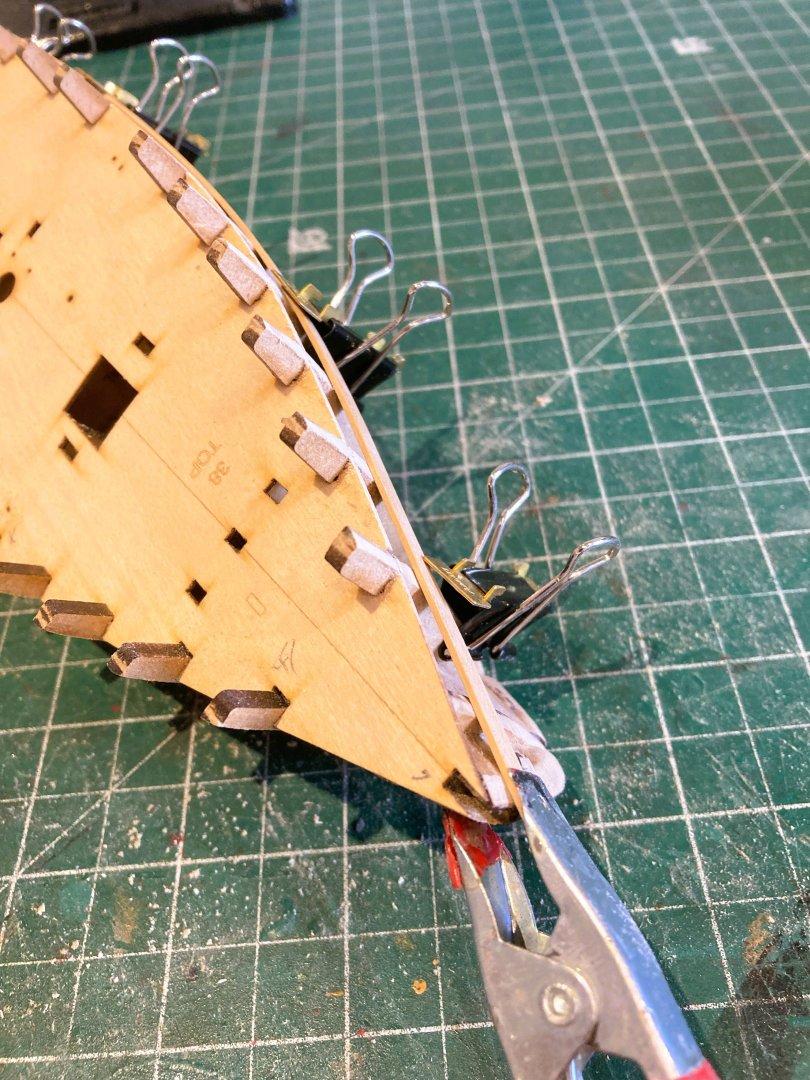
 Post 11 The slog of planking continues. Here in England’s currently not so pleasant land, January has provided day after day of cold wet weather, perfect for settling down for this sort of repetitive exercise. You get into a rhythm a bit like Rattlin’ down. Measure, Mark, taper/edge bend, test, and glue, clean and move on. 6354a Following dry fitting the planks are pinned in place and blasted with the hairdryer on hot before gluing into place. 6356a 6357a I have continued to form the strakes in three plank runs, easier to handle when using cyano. 6359a 6361a The strake above the Garboard is now fitted, leaving six strakes to go each side. 6389a There is an awkward area where the strake meets both the stern post and lower counter which would otherwise need filling. The counter was trimmed slightly to allow passage of the plank. Not quite sure whether this plain part of the counter is a kit simplification, it just looks a little odd to my eye. In practice would it not have been framed and planked similarly to the engraved plank marks below the counter? 6392a Five days effort and three strakes to go, one top, one bottom and a final spiled strake between. B.E. 31/01/2026


-
The plates should start at the keel from the stern post forward. The Amati plates are handed port and starboard, and the nail impressions run across the top but not the bottom. This is to give the impression of an overlap when the plates butt against each other. At this period the strakes proceed upwards and are trimmed level with the waterline where they cross. Worth redoing I would say. B.E.
-
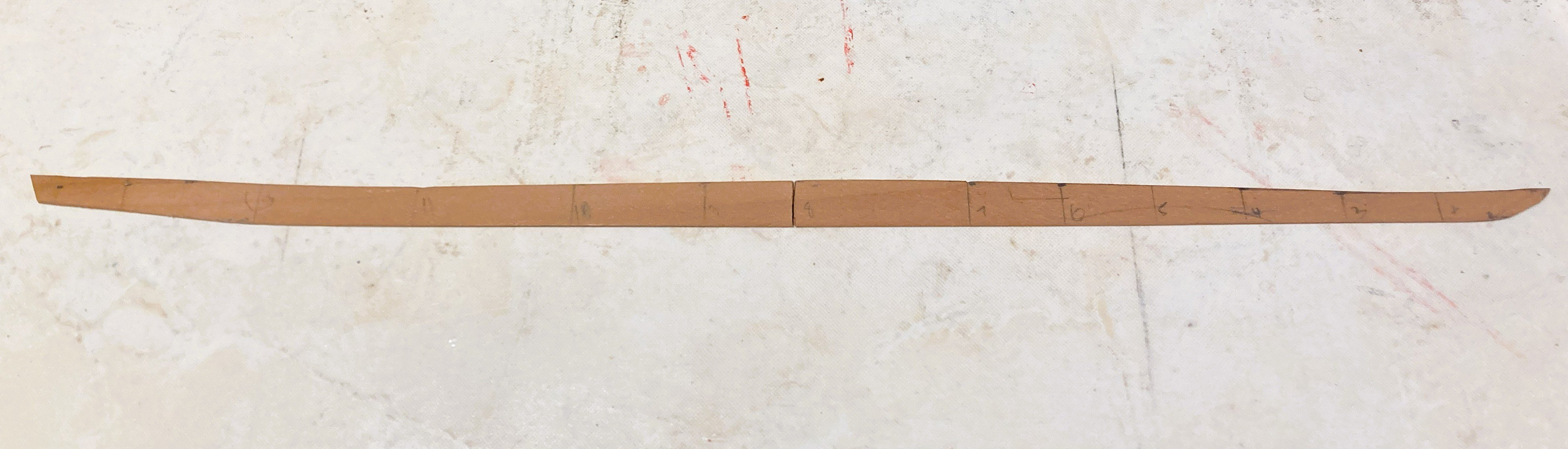
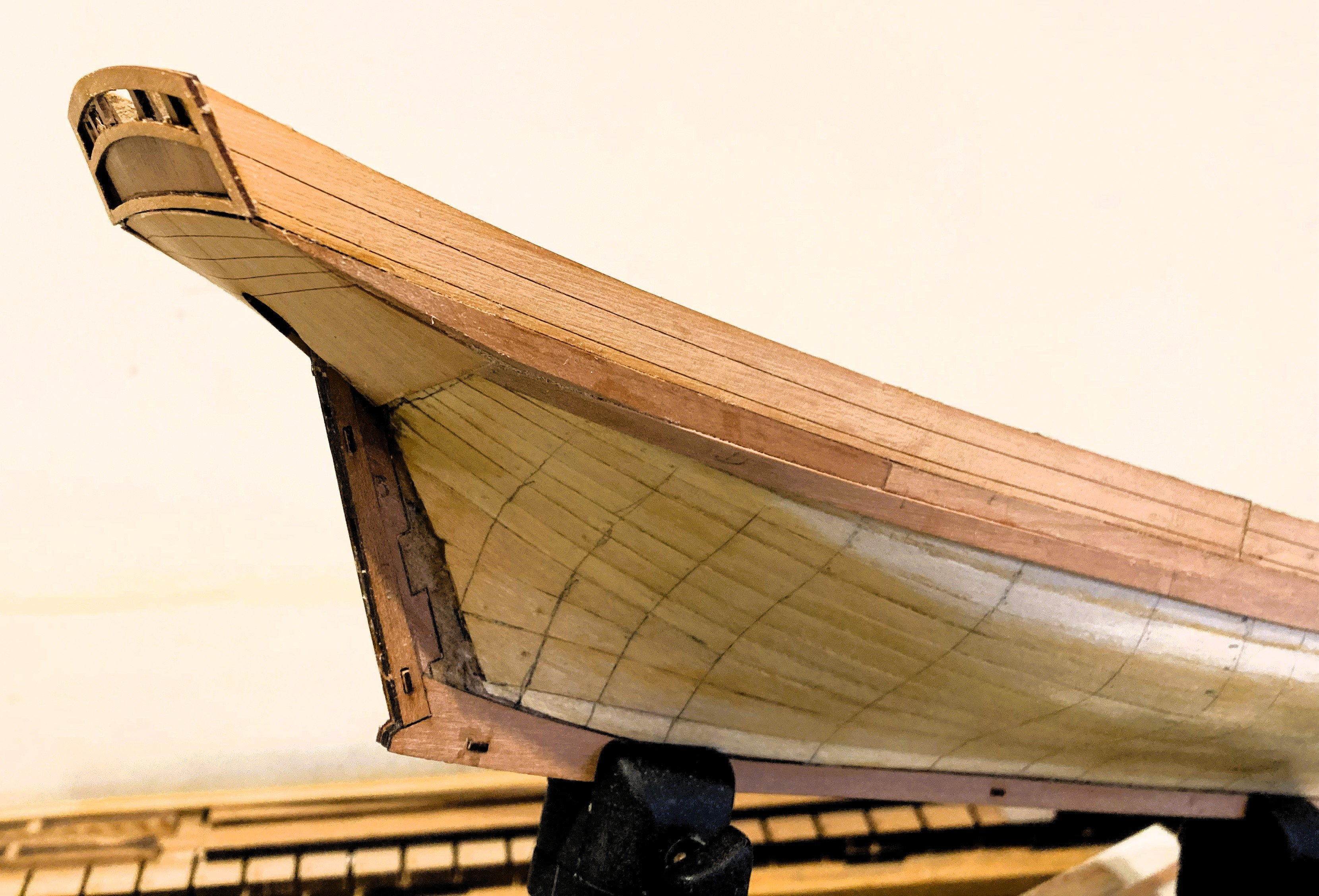
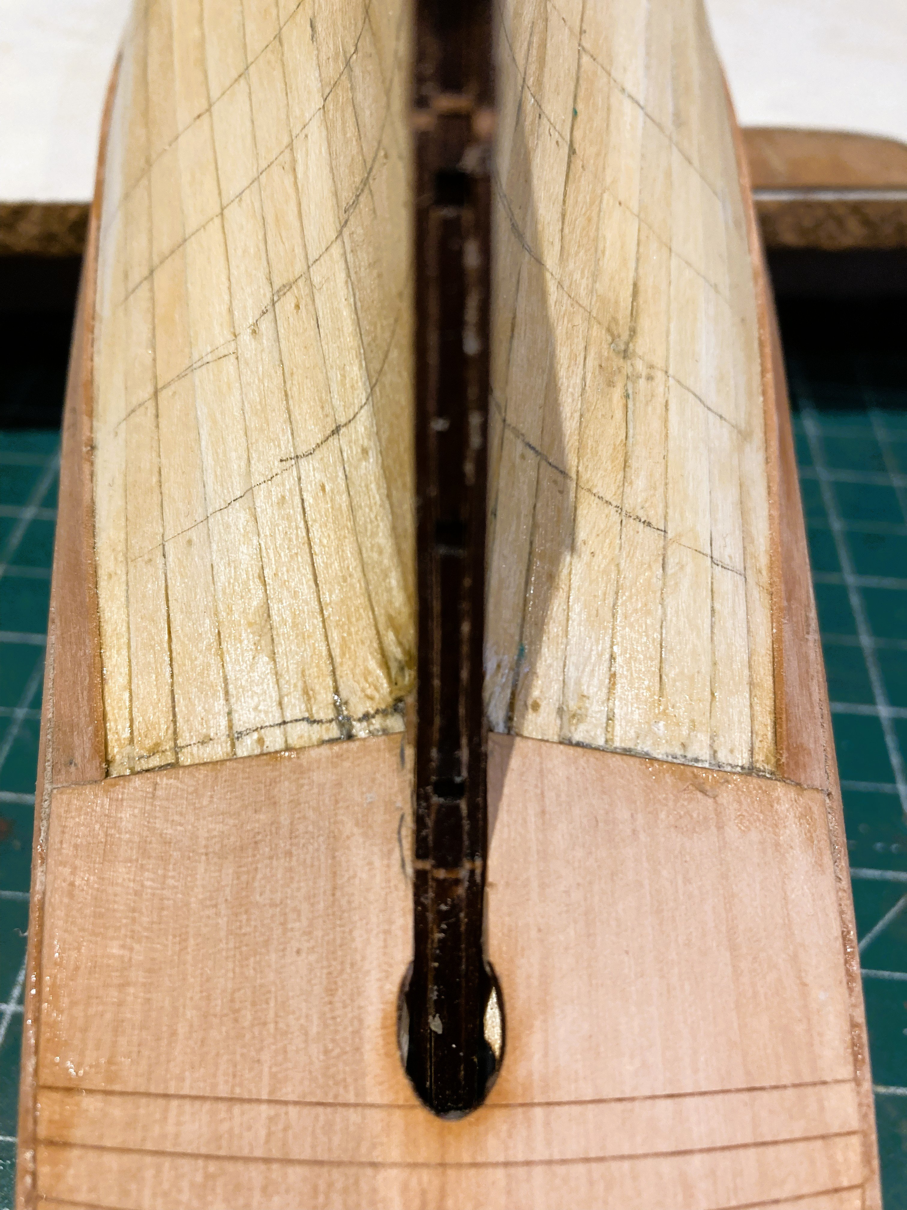
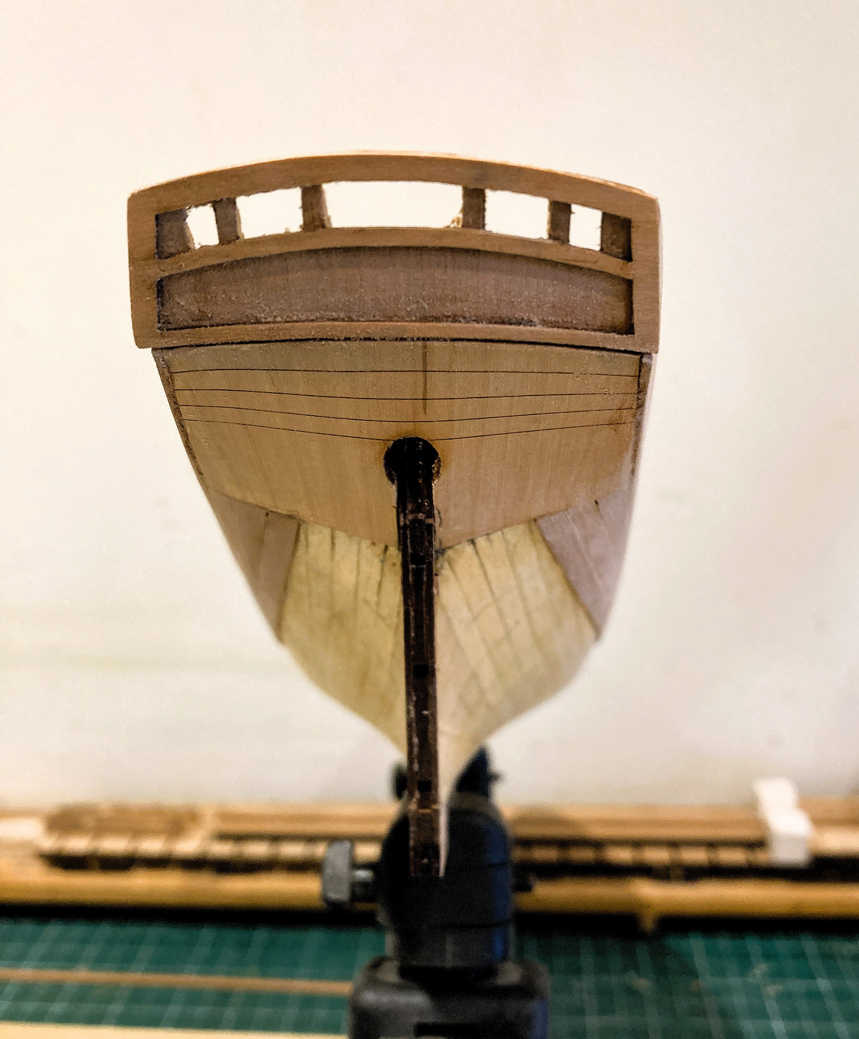
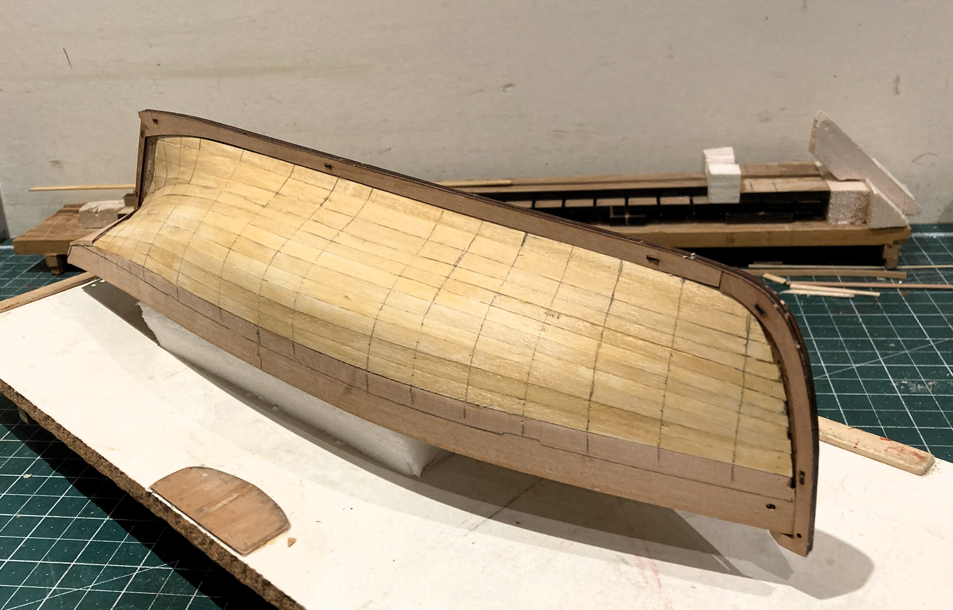
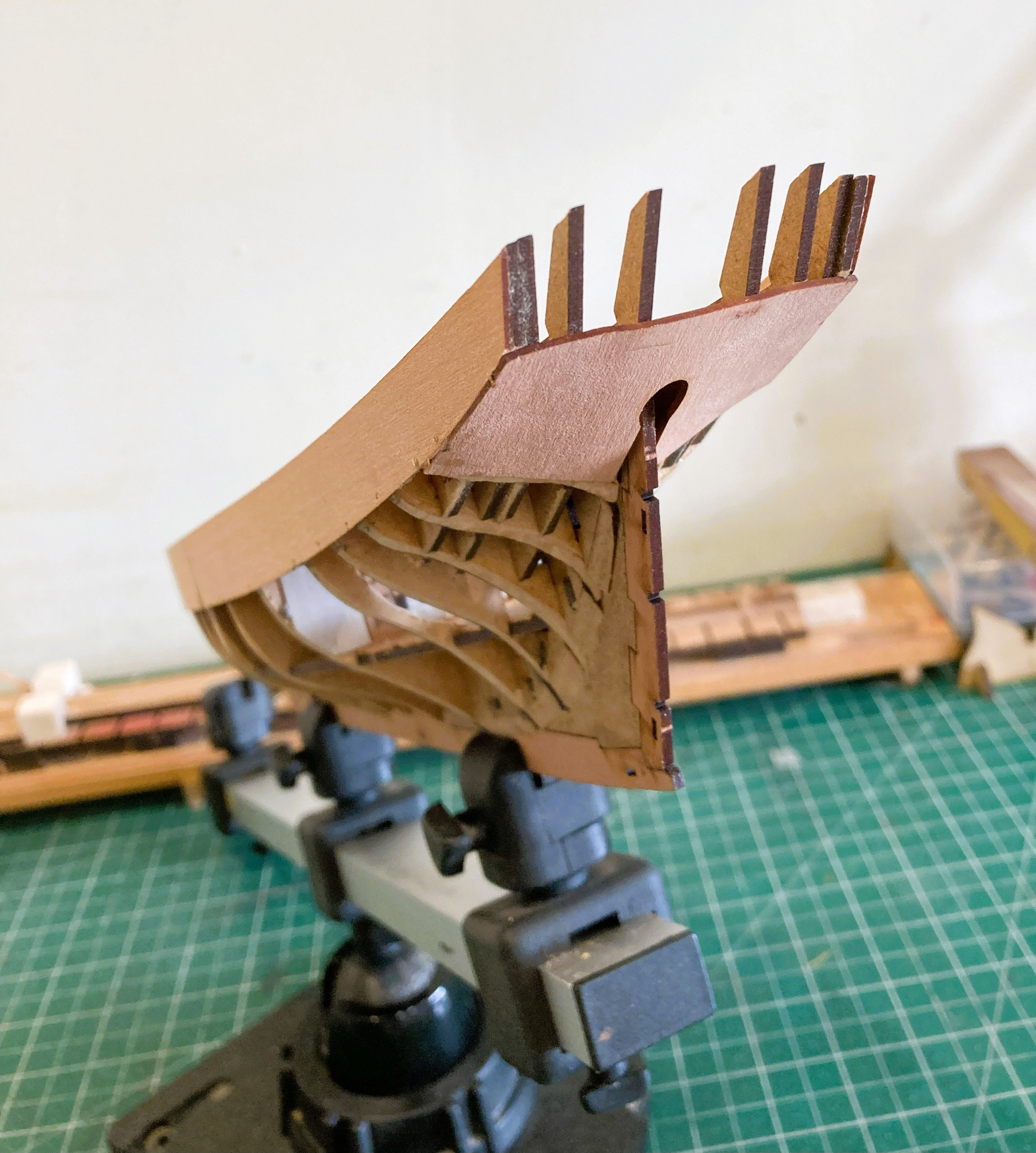
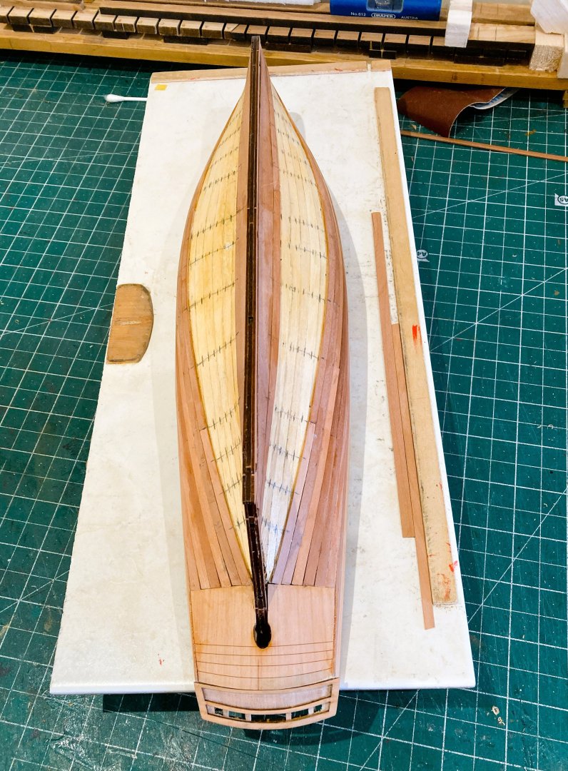
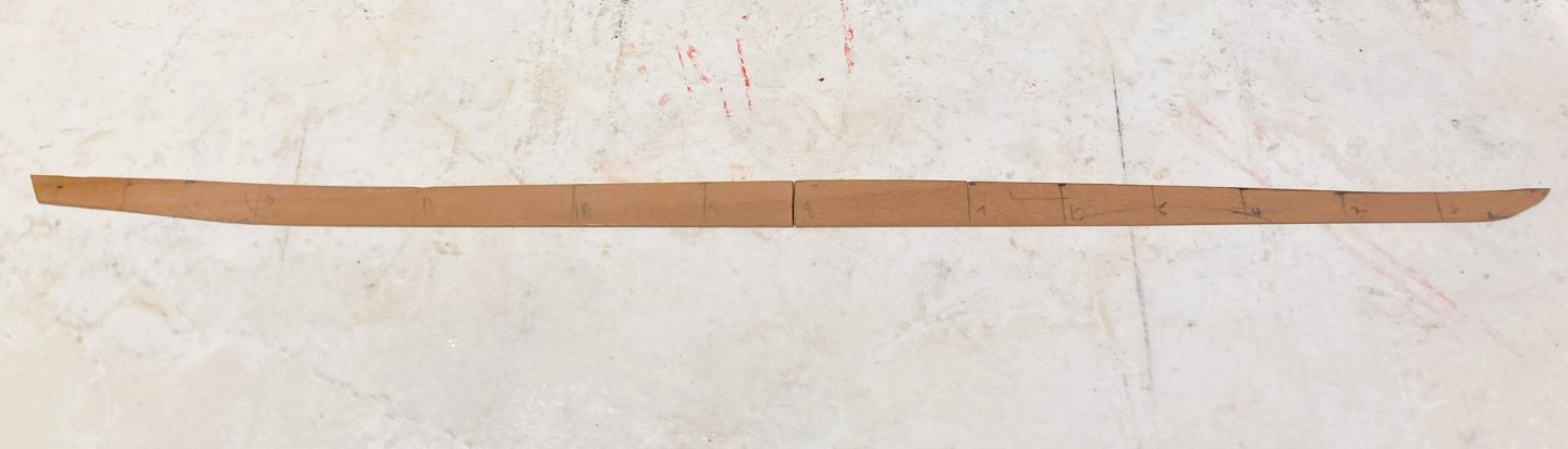
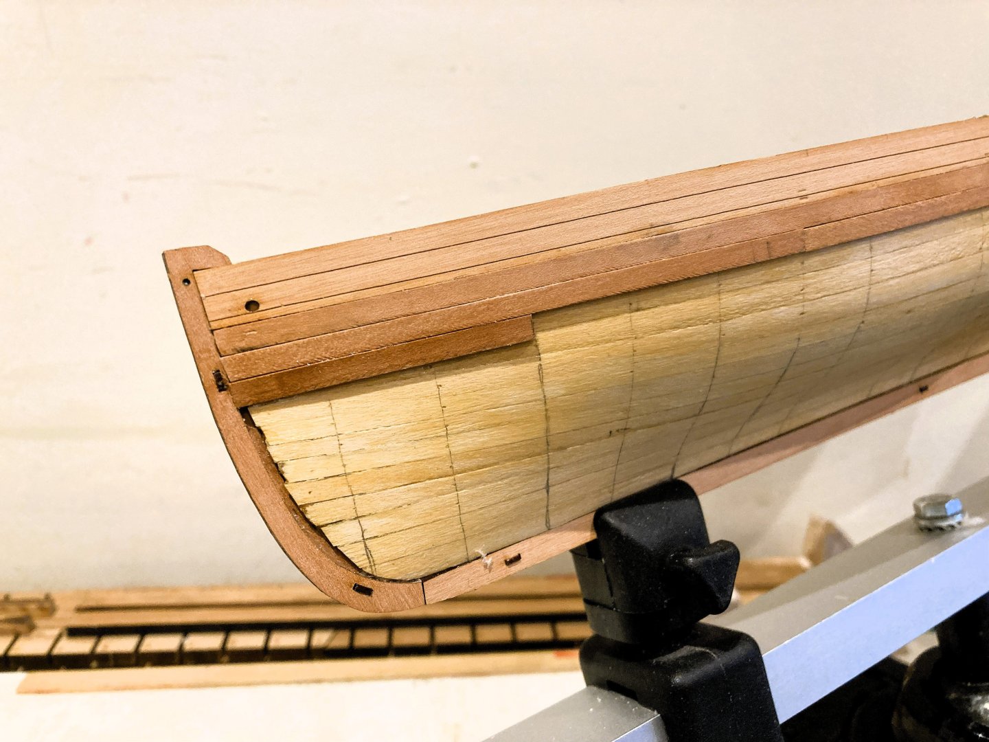
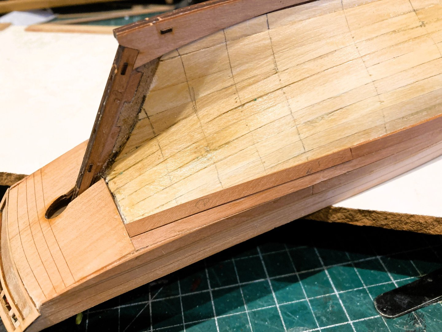
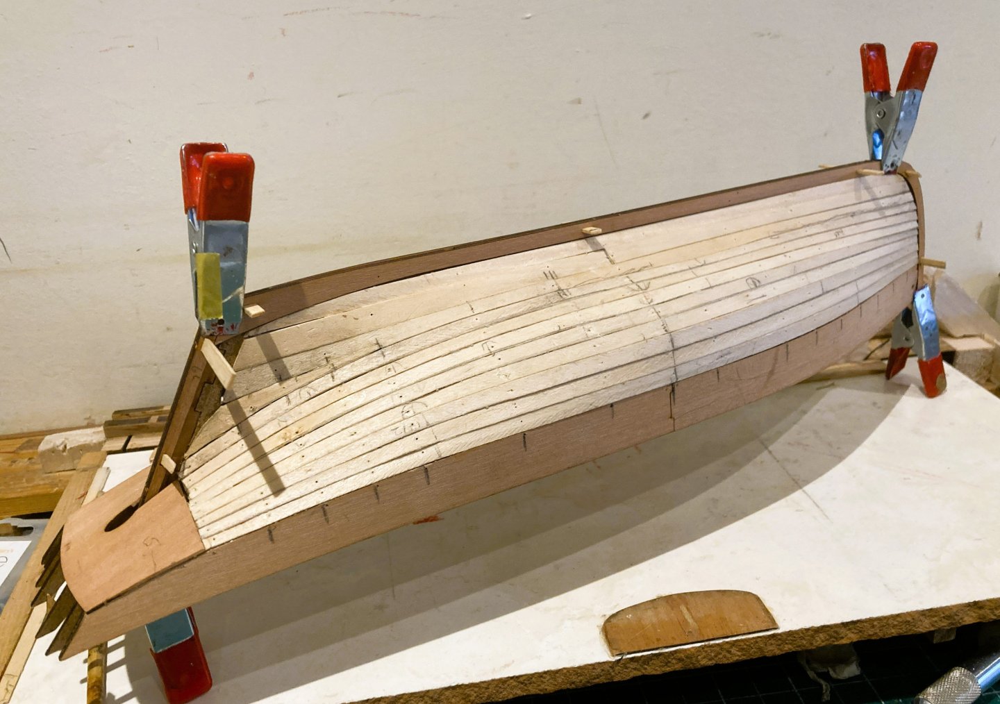
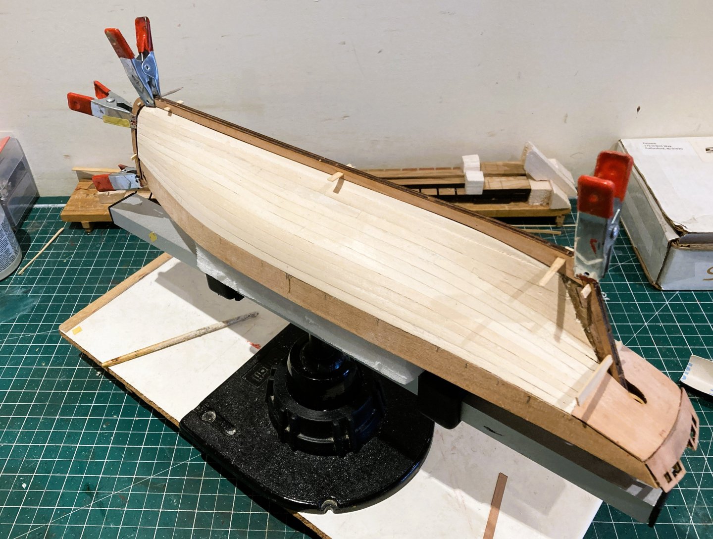
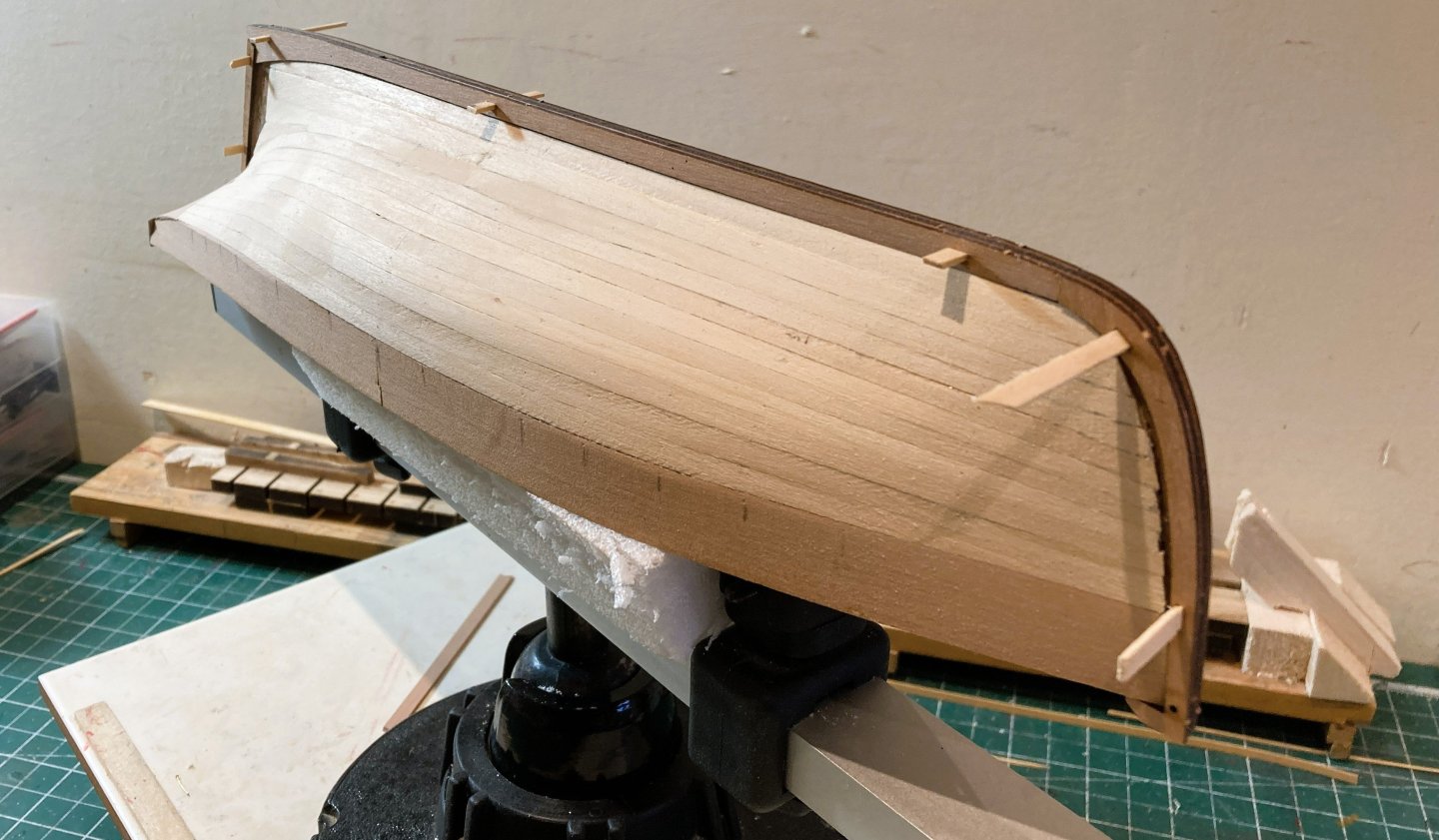
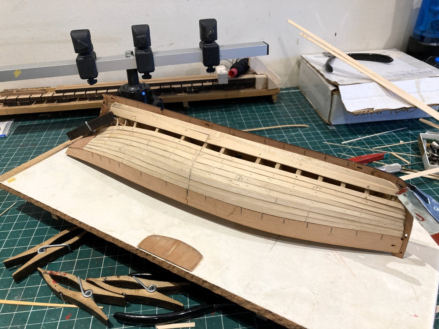
Post 11 Pearwood Planking 2 6317a The hull has now been marked off for the planking runs. 6320a As I progress these will inevitably be adjusted and re-marked. At this point I move onto the Garboard Plank. 6321a For simplification I am using 10mm wide strips which are spiled to cover the lowest two marked strakes. 6232a A little over-scale, but Garboards were generally wider, and given the position they do not visually impact on the model. 6326a This is fitted in two sections for ease of handling. 6332a The aft section is a little unusual in that I have spiled it to follow the upswept line of the keel to meet the stern post. 6338a The alternative would be to have the Garboard terminating at a point short of the stern post. 6340a The next post should see the hull planking completed. B.E. 26/01/2026


-
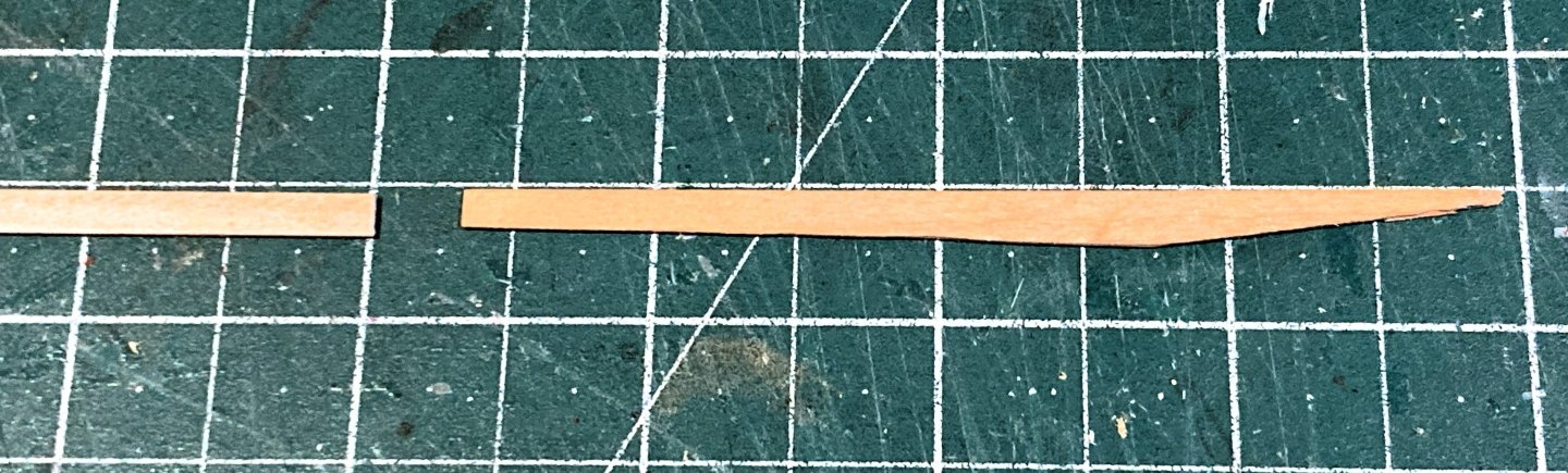
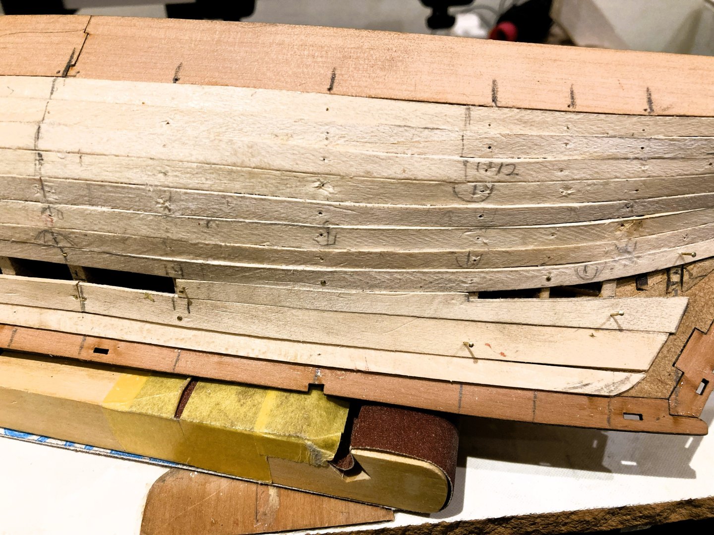
Post 10 Pearwood Planking. The kit provides 1x4mm Pearwood strips. With the outer planking I pay far more attention to variations in the thickness over the length of the strips, and particularly the colour match. I generally like to leave the broadsides unpainted to display the beauty of the wood, and the timber colour match certainly above the waterline is important. I dislike the striped effect often unavoidable in kit provided timber. On my larger projects I dispensed with kit timber all together and obtained matched sets from Hobbymill EU. Sorting the timber in my kit there are three distinct shades. Pale Pink –-------- 9 strips Dark pink Incl Brown tones –- 10 strips Medium Pink –------ 16 strips Not quite sure at this early point where that leaves me for choice, and within the planking strips there are a few less than ideal with saw scars and varying in thickness along the length. Below the waterline the hull will be painted, so a match is not needed. For gluing I am using Roket thick cyano. I dampen the strip where the cyano is to be applied to aid adhesion. To avoid marring the Pearwood surface I keep acetone and a cotton buds handy for a quick wipe-off. Better get to it… First strake below the pattern. An odd one this, the given strips are a tad short to run the full length of the hull. This first strake terminates with a sharp point where it reaches the stern board. 6230a I decided to fit this strake in two sections, the Bow section running to the fourth bulkhead from aft. I fitted this without any taper or edge bend. 6233a A tapered wider 5mm strip was shaped to cover the lower counter edge and run to the stern. I preferred this option to the alternative of fitting an awkward filler piece. The second Strake 6245a I fitted in three sections and again without taper. 6260a 6247a The aftermost plank does require a good bevel and some twist where it meets the counter. The third strake down also takes full width planks, and the strake comprises four lengths. 6261a I do like to represent the planking butt joints and give a nod to scale lengths but don’t plan the layout precisely. 6262a This aftermost plank involves bevel and some twist. The fourth strake has three planks, again all full width with only bevelling and some twist for the aftermost plank running to the counter. 6304a 6302a 6311a 6306a I will now work out the Garboard Plank dimensions and line off for the remaining infills. B.E. 23/01/2026


-
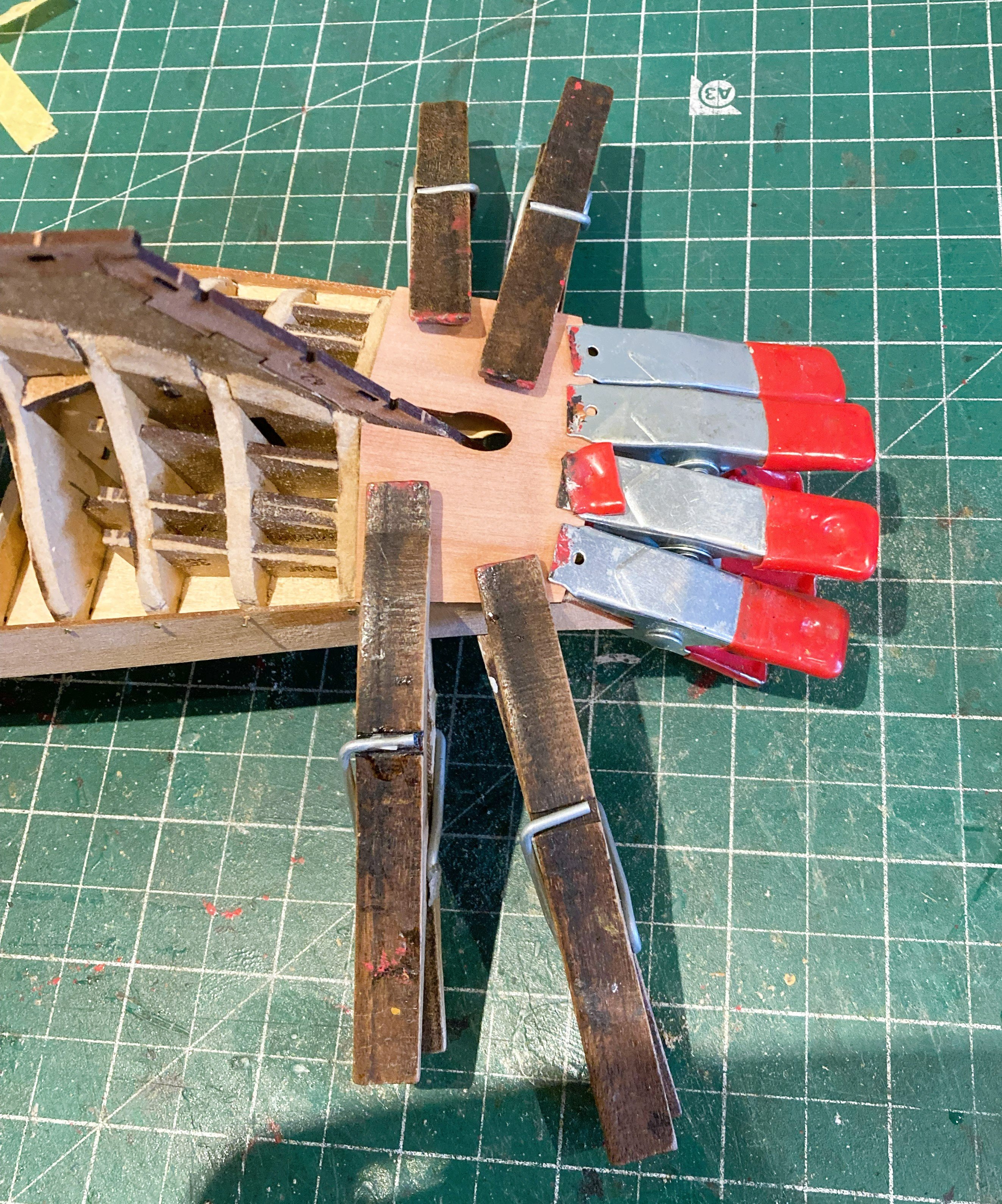
Post 9 Prepping the hull for ‘show’ planking. The Pearwood lower stern counter (outer) now needs to be fitted. This forms a rabett for the planking that sweeps up to the stern. 6209a Before gluing, the part is clamped into place and heated using a hairdryer to take the spring out of it. 6215a 6213a The patterns that cover the keel, stem, and sternpost are also glued and pegged into place. Before fitting the Bulwark outer patterns, the bulkhead positions are marked on the planking. Sanding sealer has been applied to the Limewood hull. 6220a The final action is to glue the Bulwark outer pattens in place. This presented me with a small problem in that the Holes for the Bowsprit and hawse did not directly align with the inner pattern, something I recall from one of the other build logs. No matter, I’ll sort it when I come to that point. 6222a I slightly bevelled the inner side of the pattern at the bow to allow it to sit flush with the stem post. 6223a I fitted both sides as they lay, squaring at the top. It is important that the stern Frame surround meets the bulwark patterns cleanly at the stern without any gaps. 6227a I fitted this piece in advance of the stage indicated in the Manual. Fitting at this point has no impact on the planking to come, and I was keen to repair the Stern Board fitted earlier. Pearwood Planking up next. B.E. 19/01/2026


-
Post 8 Fettlin’ the Limewood. The planking at the stern has been left short of the sternpost as it would in any case have to be thinned to a feather edge to accommodate the outer planking. 6185a I test fit the Pearwood outer strip patterns used to cover the keel, stem, and stern posts, and form a rabbet into which the top layer planking will fit. The keel pattern is used to trim the Garboard plank around the bearding line. 6196a What a difference a sanding makes. Sanding the first layer takes very little effort, P120 paper is used to get the rough off followed by 320 and finer papers. 6208a Any small irregular areas are filled with lightweight filler until the hull passes the blind feel test. 6205a 6203a Nearing completion I again use the patterns to check the fit of the outer Pearwood planking against the formed rabbets, paying special attention to the bow and stern areas. The final stage will be to apply sanding sealer to the hull. B.E. 16/01/2026
-
She's looking good David, pretty little thing ain't she. B.E.
-
You’re making wonderful progress Ronald, and I fully concur with your sentiments about the small touches on your model. The thing is whatever others may or may not notice, your eye will constantly be drawn to it. From a carpentry aspect that sort of butt joint on the rails looks amateurish, and the end grain looked ugly which is why I changed it. From a purely historical view point the real Sphinx would have been much plainer in appearance, without all the Topside decoration. For my build I wanted to reflect the image as shown on the Joseph Marshall painting, which pleases my eye and provided an additional challenge in replicating the counter decoration. You are going to produce a very fine model. Regards, B.E.
-
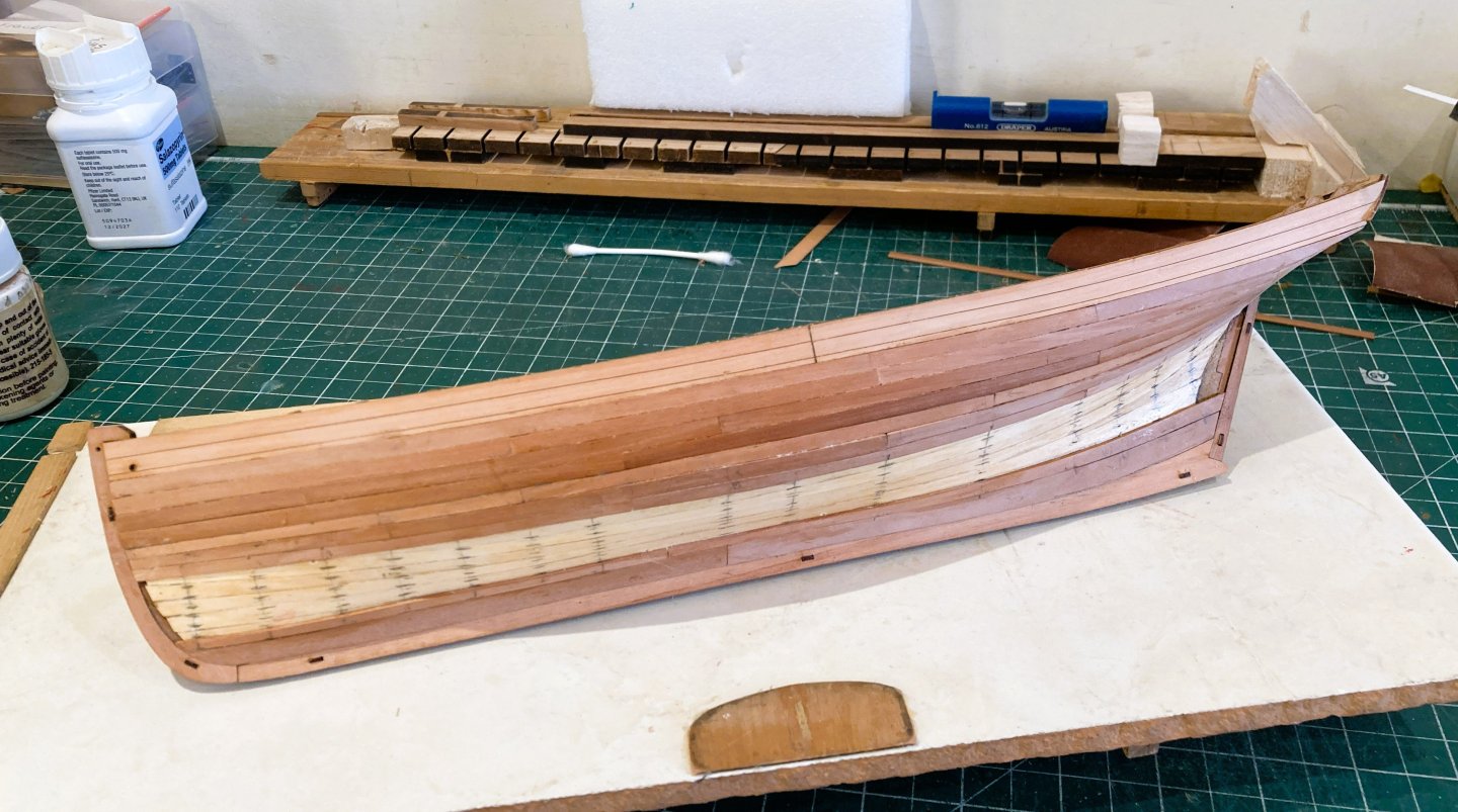
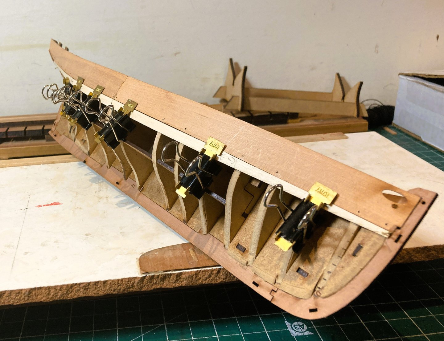
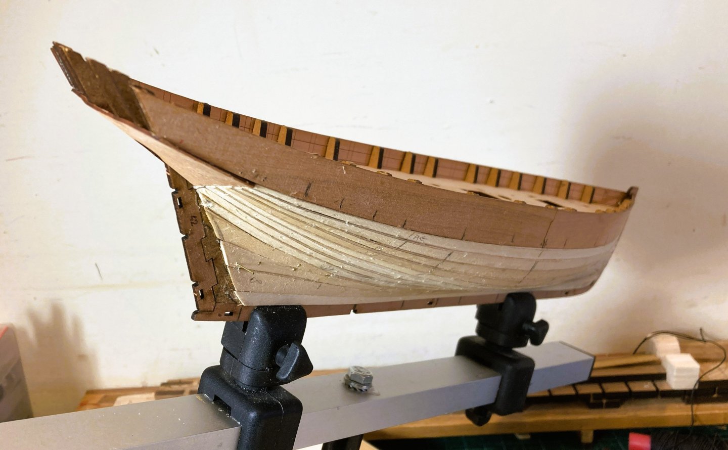
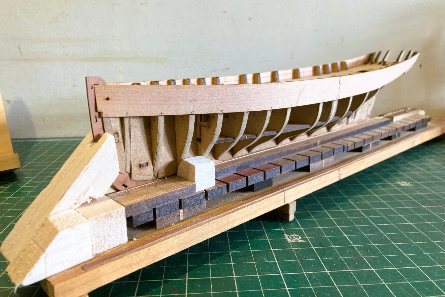
Post 7 First Planking. I begin the first layer planking using the kit provided 5mm limewood. Somewhat inconsistent in conformity but sufficient for the purpose. I wasn’t overly concerned about thickness and depth issues in the timber on this first layer, and I used non kit broader limewood strips for the lower strakes running to the stern post, which naturally require wider strips. 6124a I have applied taper from the outset, and the stern section also requires bevel and twist to meet the counter and sit tight against the Bulwark patterns, particularly towards the stern. 6125a With the first layer planking I use a simplified tick strip approach together with edge bending and bevelling which gives a useful insight to the planking runs on the all-important pearwood outer planking. I found planking Erycina particularly at the stern more involved than I recall from either my Fifie or Zulu builds. 6157a 6160a Towards the stern the strips are edge bent, pinned in place, and further heat applied from a Hairdryer on max setting. This is done before final gluing. 6171a The final strake is spiled; I use Tamiya tape to mark the shape. I used two sections to form this strake. 6166a For the Garboard plank I simply used a full 5mm strip. Above this I used broader strips (8mm/10mm) in two sections with greater flare at the stern, all these sections are spiled. The photo also shows the single drop plank I used to accommodate the upward run of the stern planking. 6178a 6183a Very much at an ‘ugly duckling’ stage, but she will turn into a graceful Swan. Trust me …..🫤 At this point the stern board is fitted, but before gluing into place it is a good time to clean up the inboard stern timbers. 6187a These are heavy with char and it is easiest at this point to remove. The build manual photos show the char left insitu but whatever finish or none is applied, it is better removed. The stern board is a delicate piece and the centre section of the top rail did break in two places. 6191a Hopefully not too much of an issue as the outer stern frame surround will provide a guide to re-fit the broken parts later in the build. Onto that sanding business. B.E. 13/01/2026


-
An excellent and tricky conversion at 1:150 scale, she looks good.👍 Converting and detailing this kit to more properly represent a Seventy-four of the period (French in my case), proved the most difficult build I've done. Well done in both your perseverance and end result. B.E.
-
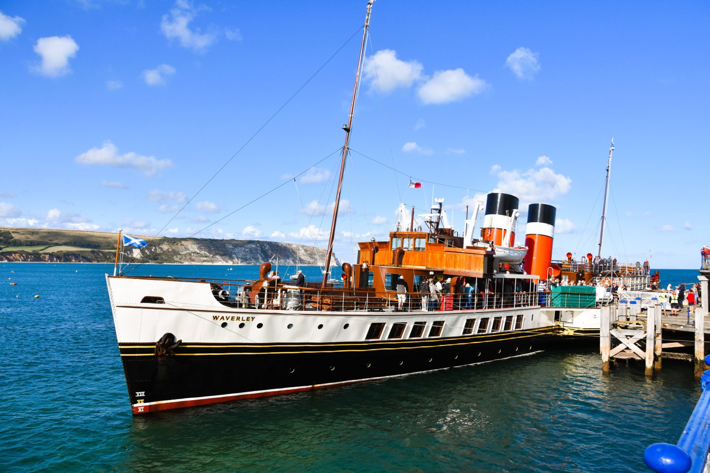
Post 6 Update In September 2025 three of my interests, Steam trains, the Paddle steamer Waverley, and castles, combined to make a wonderful holiday. 9567 I was hoping to see this locomotive dating from 1893, and it just happened that the Swanage Railway was holding its Autumn steam Gala during our stay. 9768 Here at Corfe Castle is probably the finest view from a Heritage Railway in England. 9410 I have long wanted to sail on the Waverley and there it was on a day we decided to visit Swanage and walk along the pier. A case of pure serendipity. On my return I didn’t have the motivation to continue work on my Erycina build, and there were other things that required my attention. Hence the four-month absence from MSW. Although still not fully fired up I now look to starting the first layer planking of Erycina. B.E. 30/12/2025


-
She looks a fine model fully rigged Glenn, well done. Too nice not to be on display. B.E.
- 241 replies
-
- 2
-

-
- Vanguarrd Models
- Harpy
- (and 1 more)
-
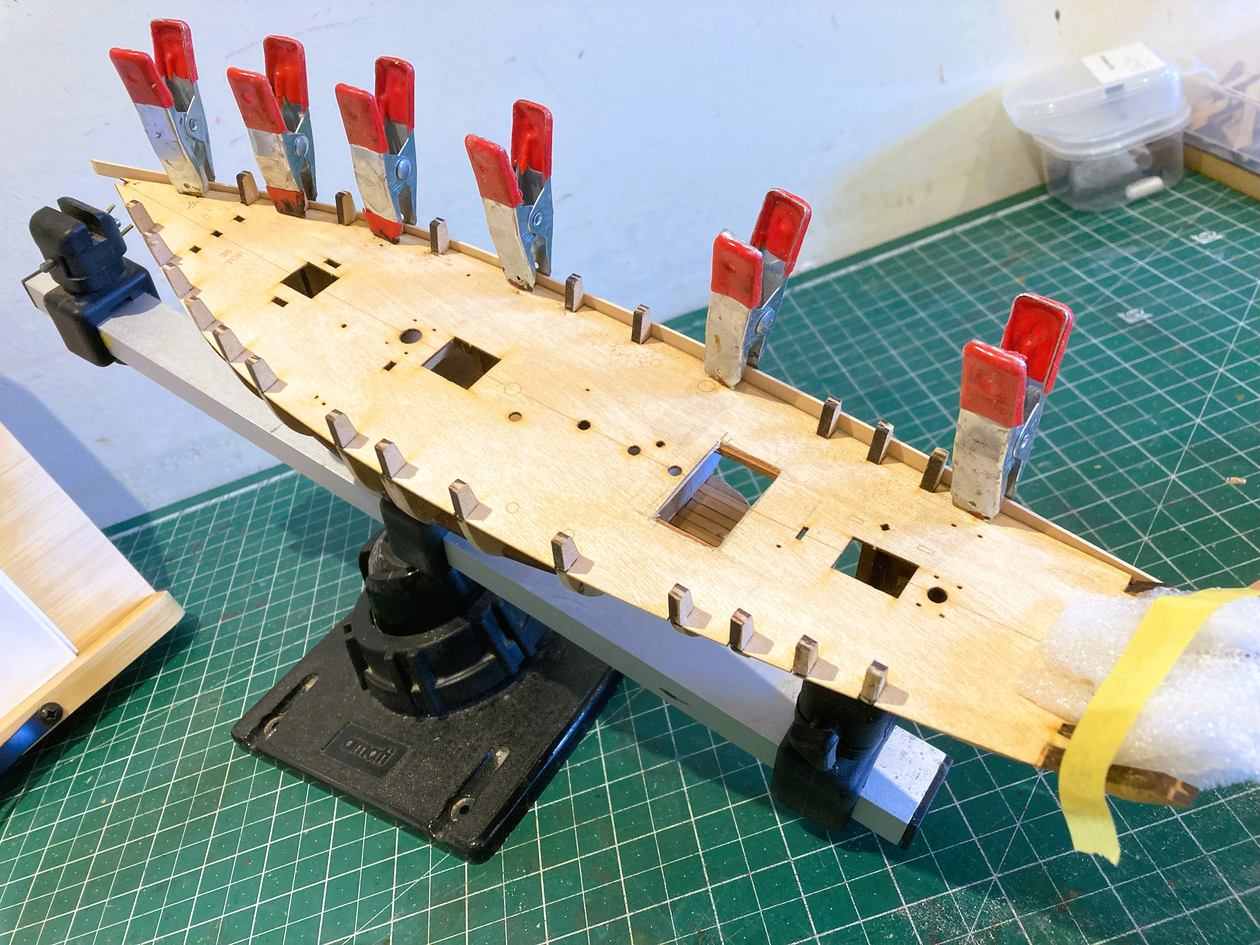
Post 5 Fitting the Bulwarks. As is usual with Vanguard kits the bulwarks come in two sections (Fore and aft) of 1mm Pearwood strip. They are marked on the interior with the frame positions and a useful fitting line which sits level with the deck line. 5623a I dry fit them and use heat to reduce the spring before gluing and pinning. 5650a 5652a Glue is not applied to the bulkhead extensions which are later removed. The stern counter frames require fairing to allow the counter pattern to fit cleanly across all frames. 5634a The counter pattern is wetted before clamping to the frames for better conformation and allowed to dry out. This can be speeded up by applying heat. 5642a 5645a With the bulwarks and counter in place the stern timbers are better secured against accidental damage. B.E. 06/09/2025


-
I regret to say that the cannon certainly is not a good example of a well made product.
-
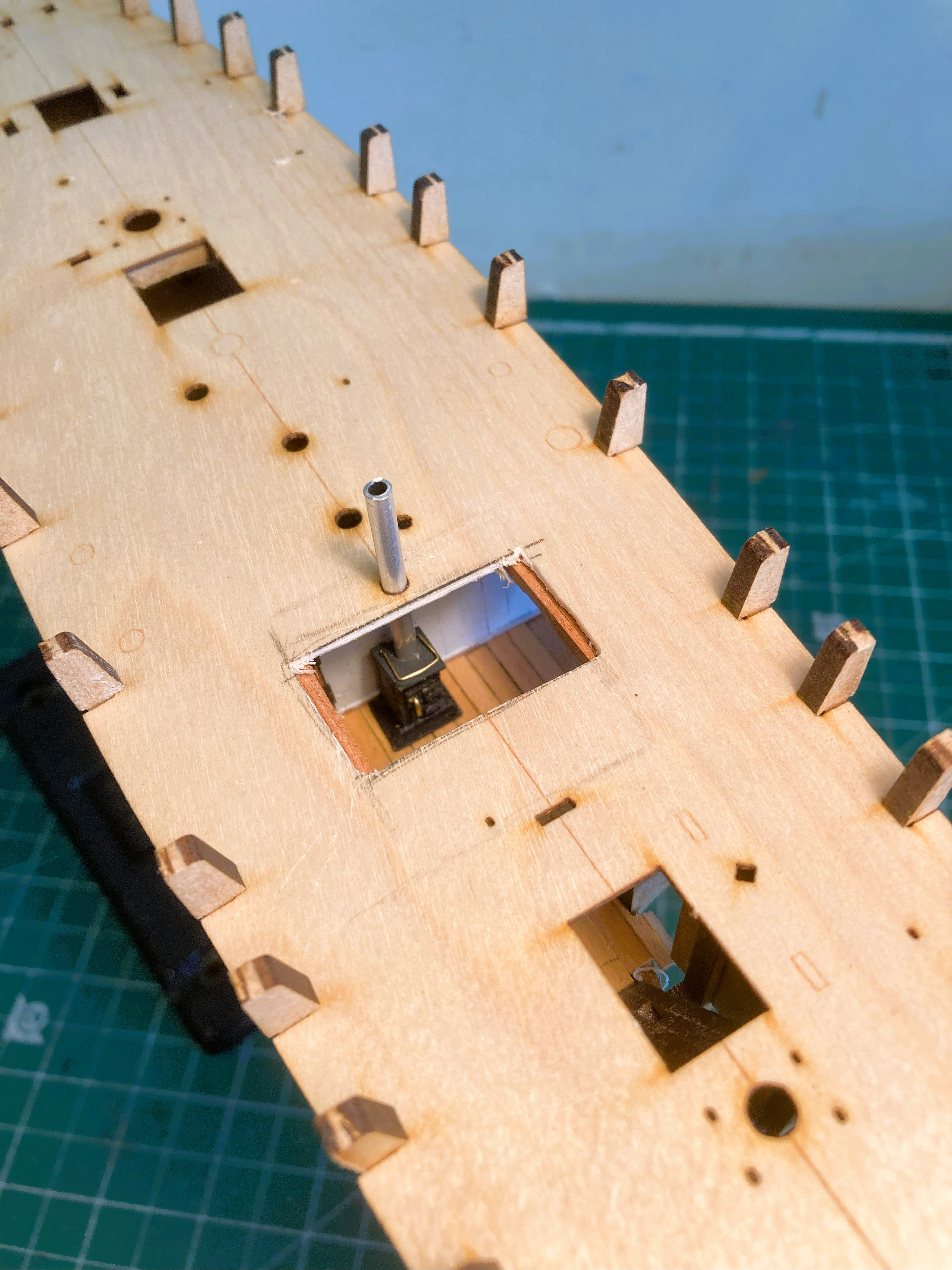
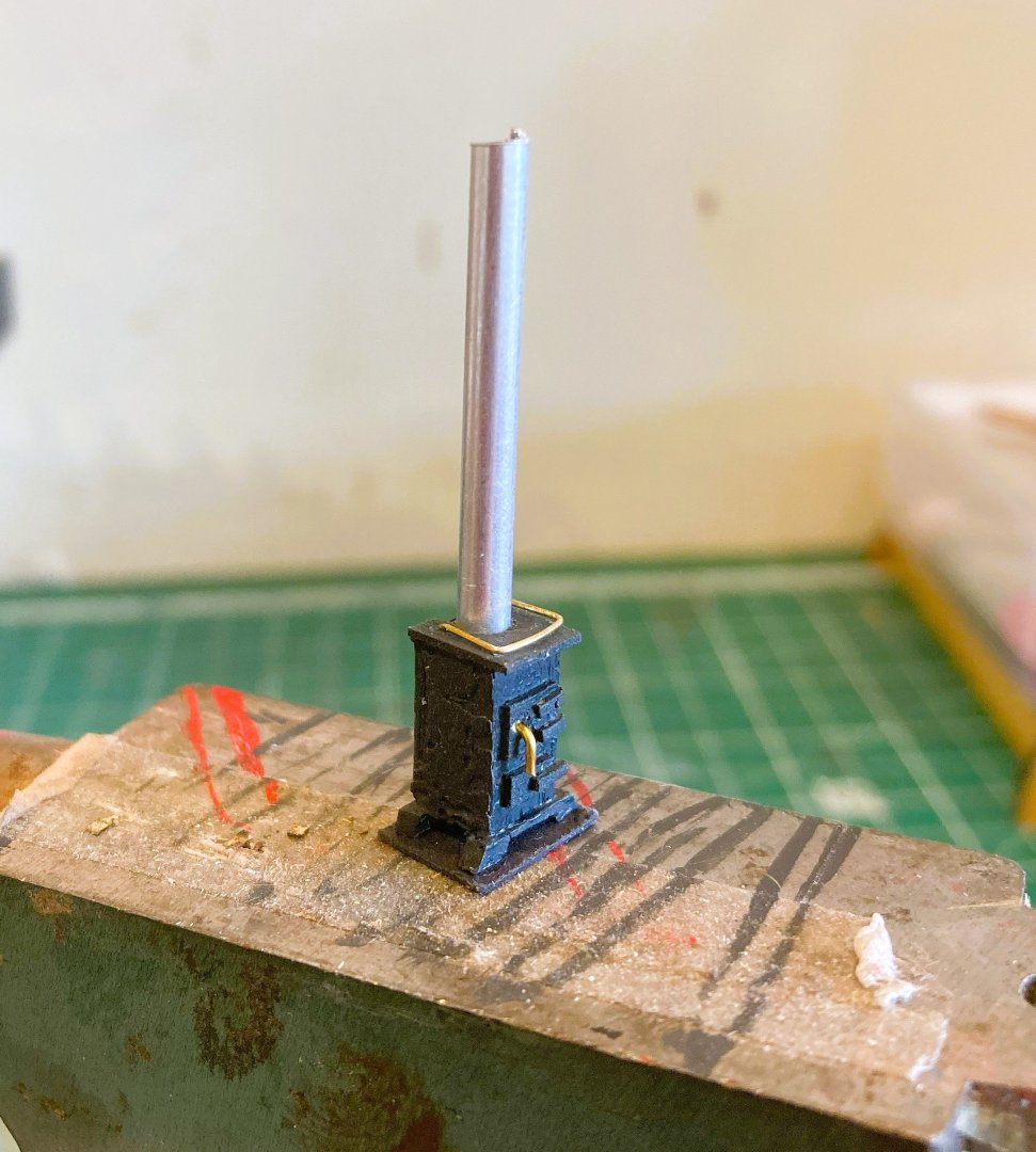
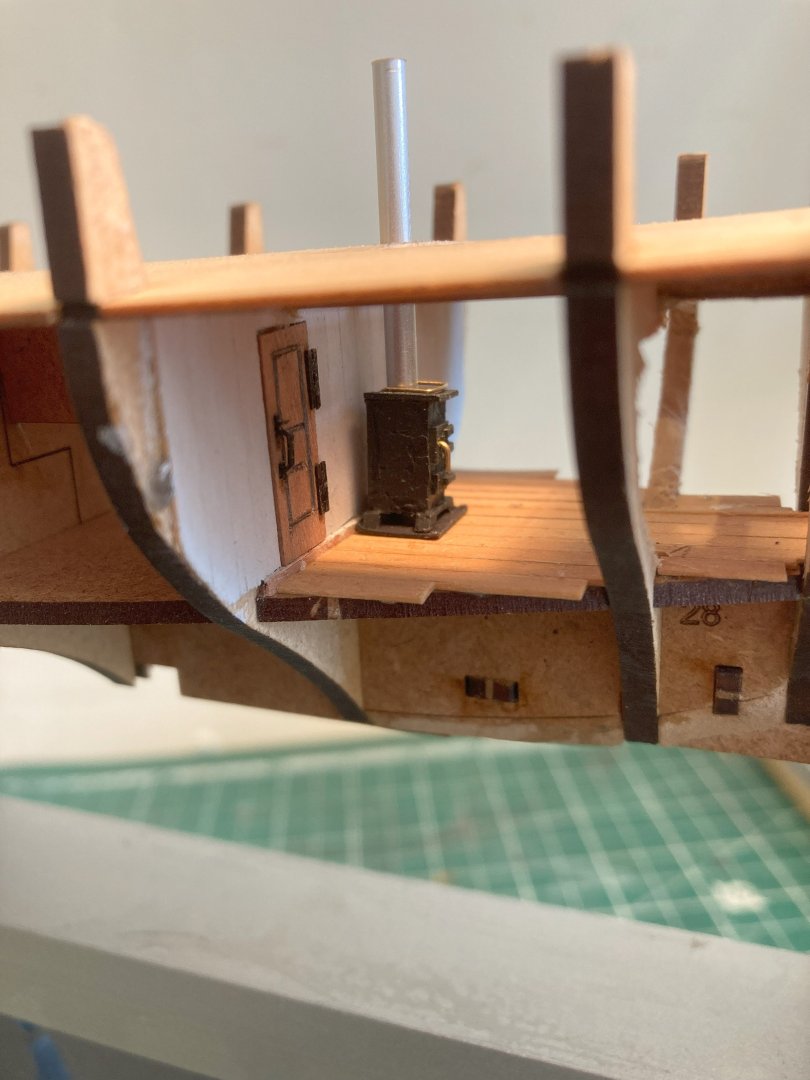
Post 4 Fairing and fittings A stove for Erycina It is certain that a small stove was contained within the cabin of Erycina but the kit only shows the Flue pipe emerging above deck. 5585a Before I begin fairing I knocked up a small stove to check the fit and position for the line of the flue pipe. It is a tiny thing measuring only 12mm x 6mm. 5593a The main objective is to see how it looks in the cabin position. 5595a I think it will pass muster, at least to a blind man on a galloping horse. Fairing is straightforward on Erycina, it’s nice to have a hull that will fit in one hand to work on. 5600a 5604a A careful check is made to ensure that a test board will fit tightly against the deck edge and bulkhead ears. 5607a 5608a Similarly, all points of the faired bulkhead edges are checked using a test board to ensure full contact down to the keel. 5612a 5616a 5620a The final stage of this section is the addition of the Pearwood keel, Bow and sternpost parts. They all slot perfectly together into the false keel. B.E. 03/09/2025


-
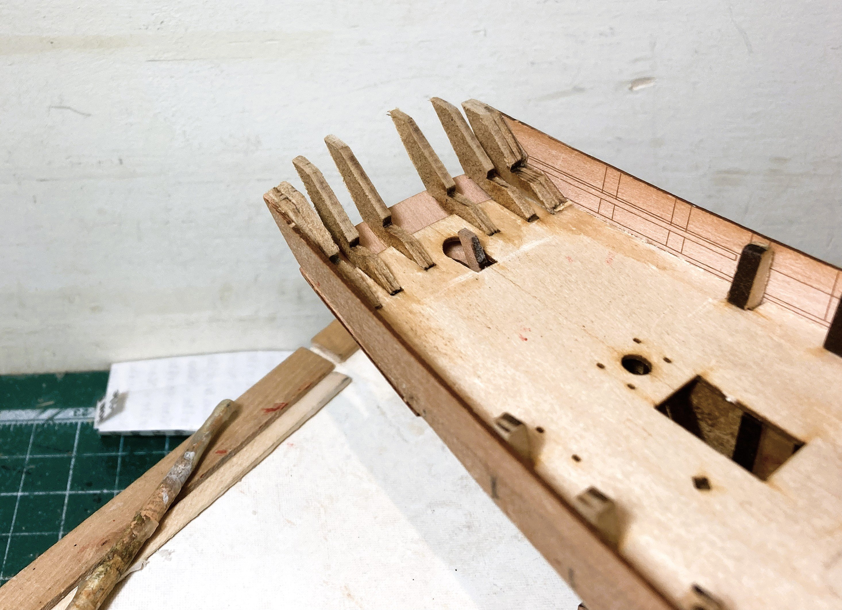
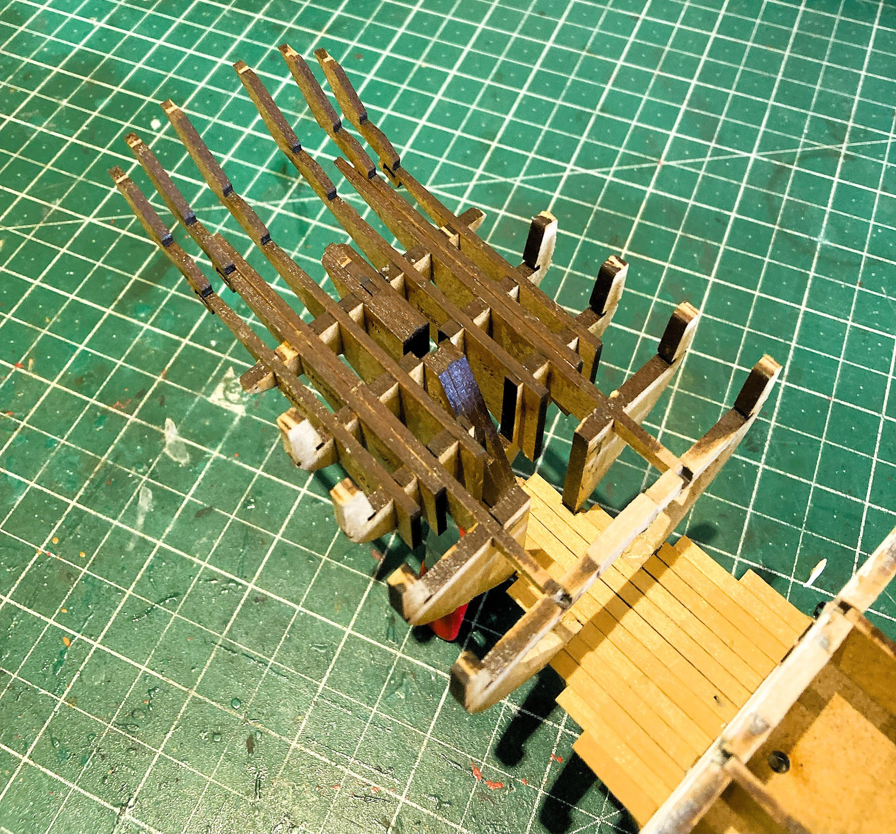
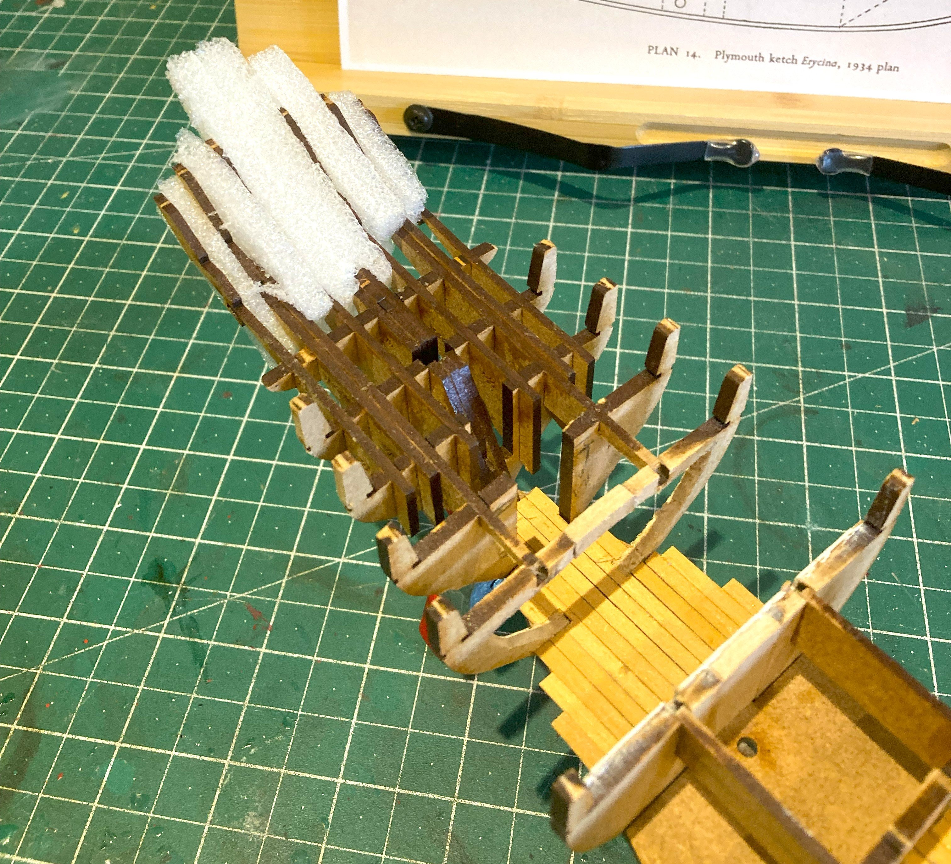
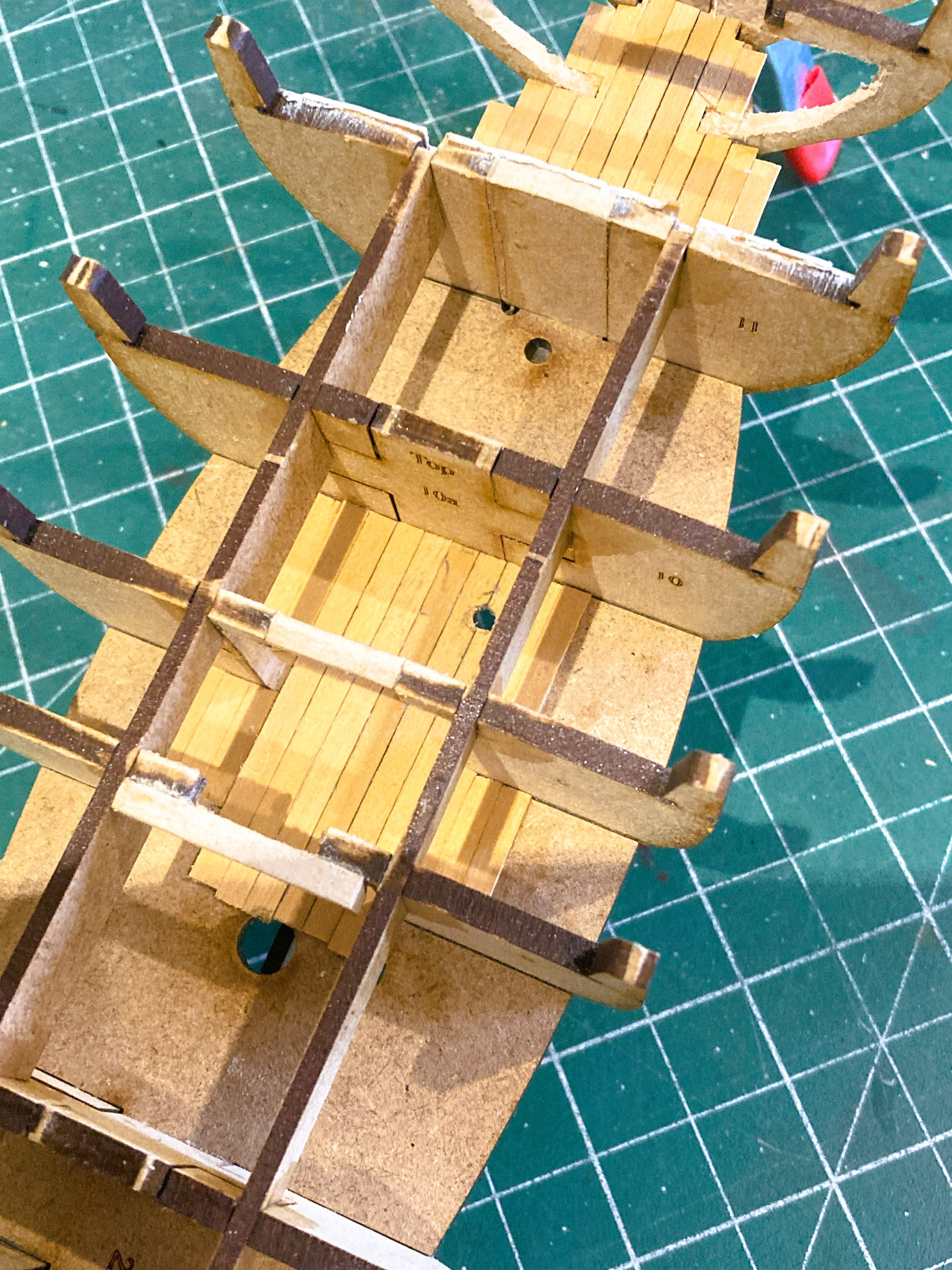
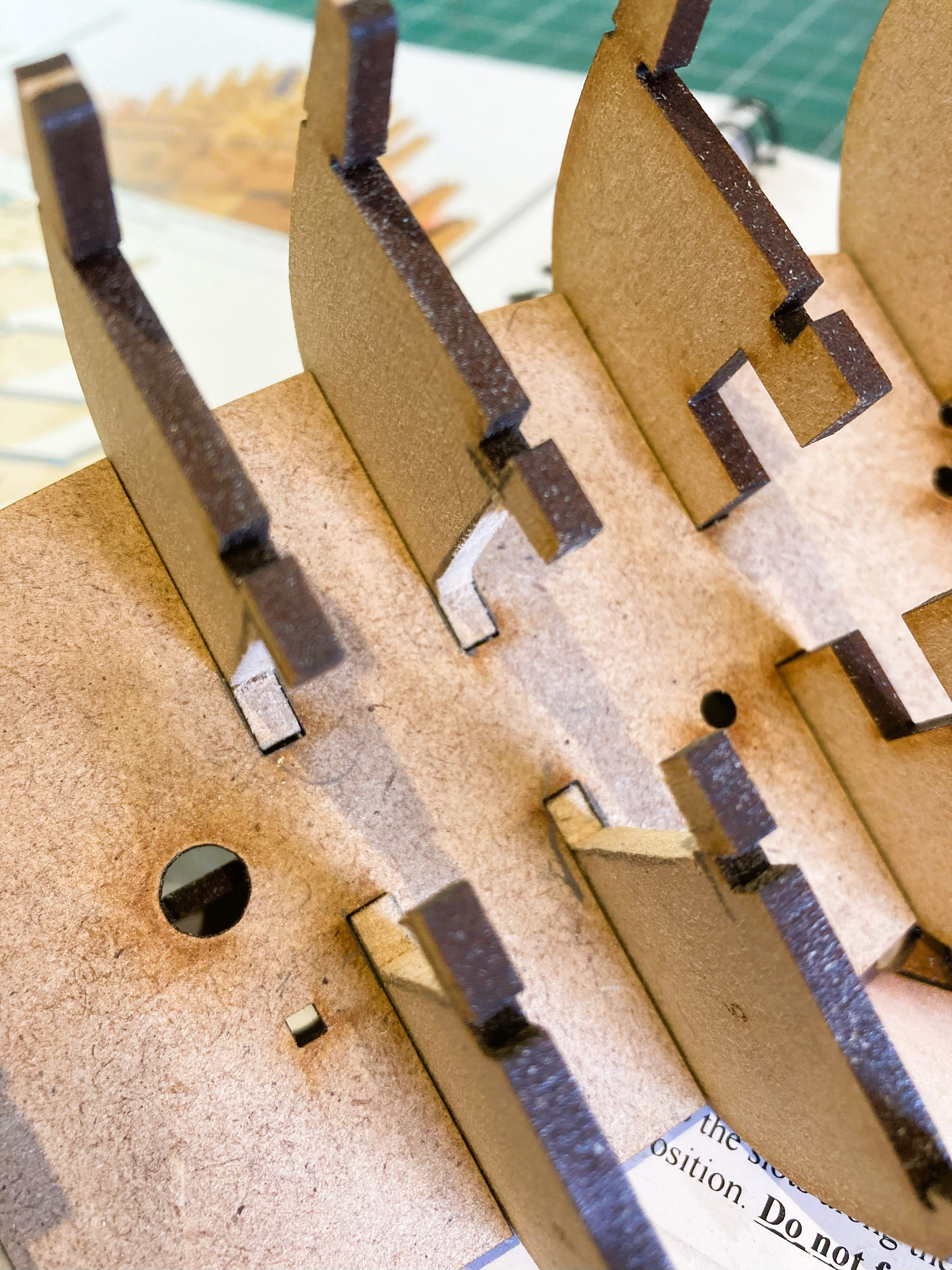
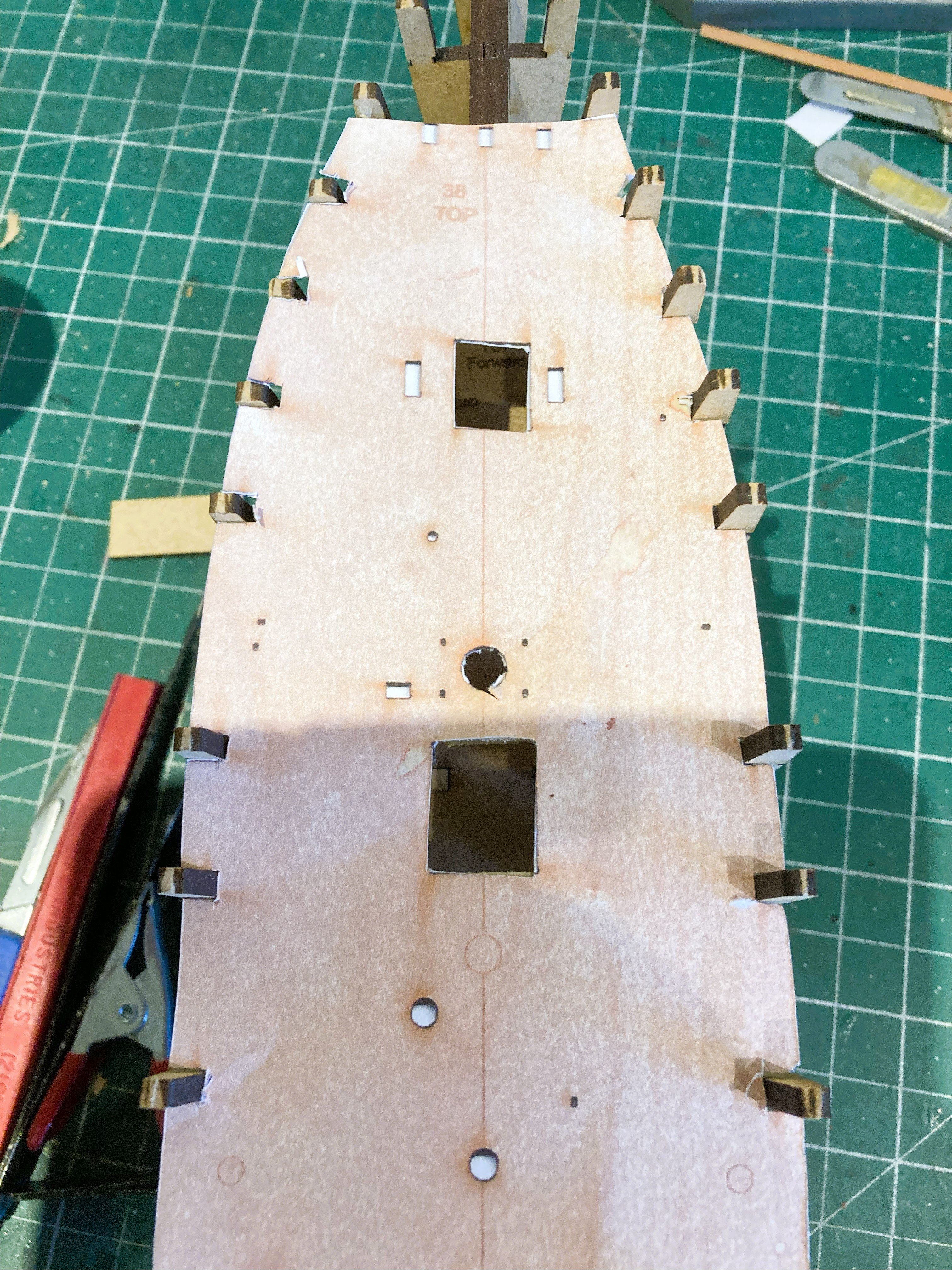
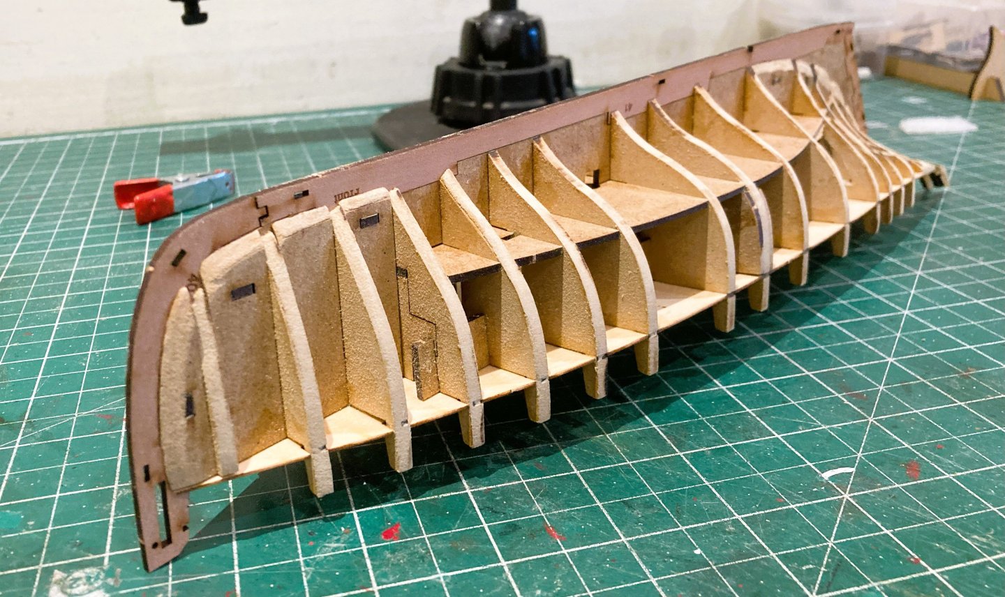
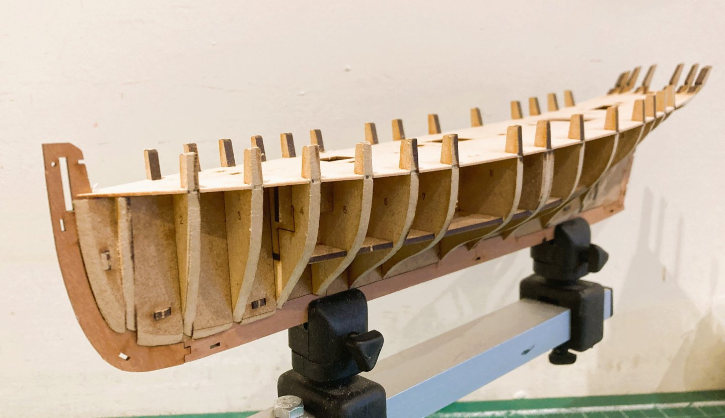
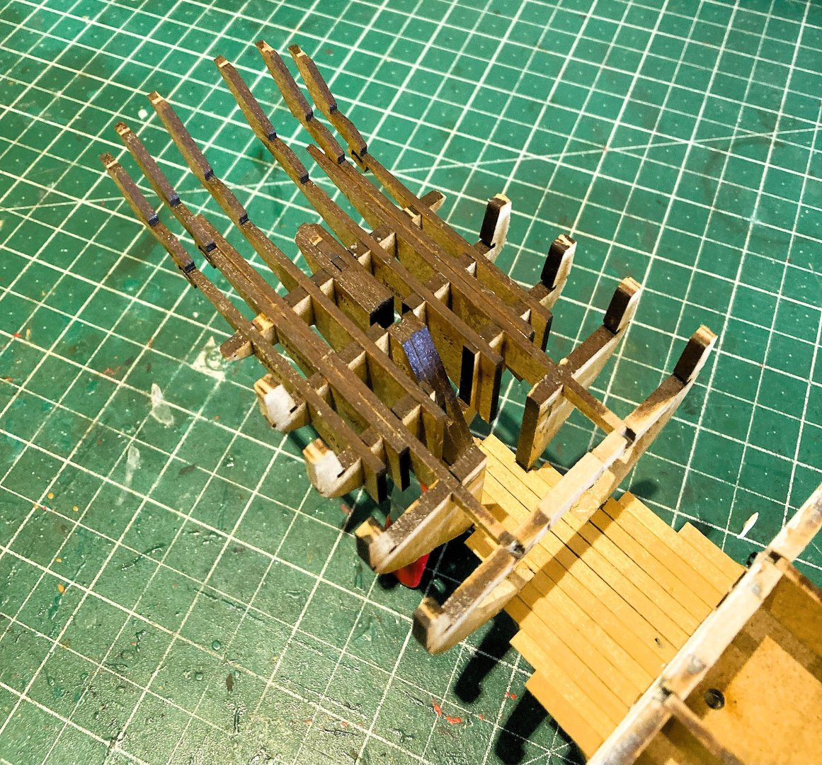
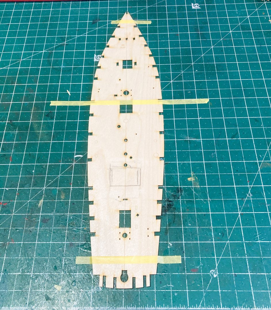
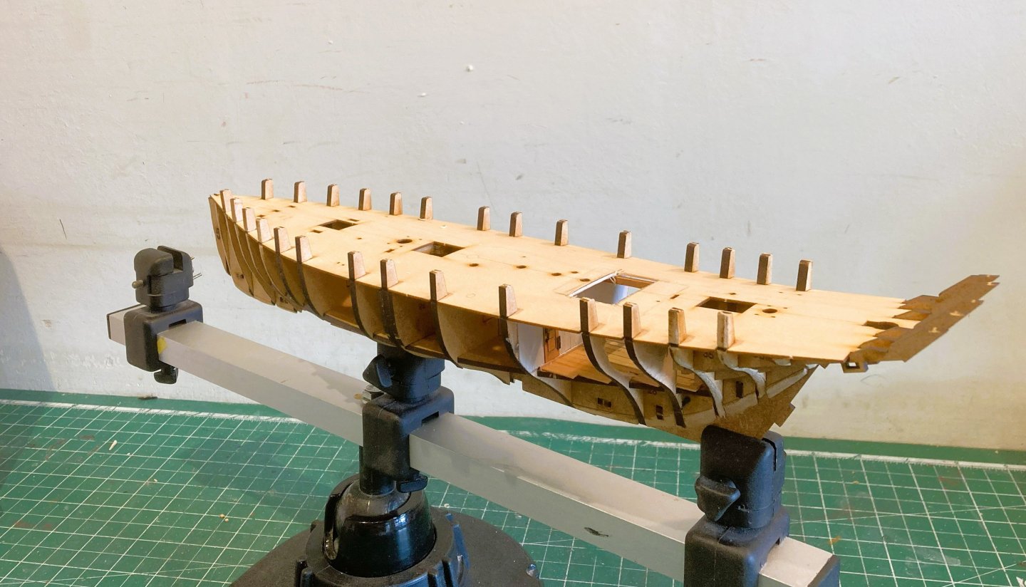
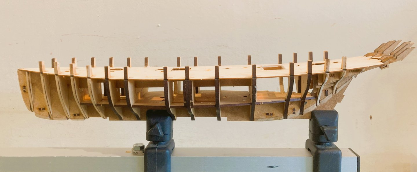
Post 3 Stern timber frames These are the long and vulnerable mdf stern timbers that set alarm bell ringing in my ears. Great care is required not to stress or knock in the early build stages; repairs could prove tricky. 5572a I found that careful sanding of the slots, and trial fitting was required to achieve a firm but not overtight fit which may have created difficulty if subsequent removal was necessary. 5573a Fitting support pieces between the timbers is advisable. I use styrene foam pieces which are ideal. Once the bulwarks are fitted this area becomes less at risk. 5567a 5569a This is now the time to fit the ply sub-deck which will secure the bulkheads from lateral flex during fairing. Another testy little exercise. 5580a The deck is taped square on the cutting mat to mark and remove the section above the cabin, a margin is allowed for some final trimming. 5582a The bulkhead slots are tested for ease of fitment and having fully inserted the deck into the port side slots I work along the starboard side from fore to aft individually flexing and pressing the deck into place at each slot. 5584a There is always fear of breaking something with this exercise, but firm and steady pressure get the job done. I was pleased to see that the deck sits tight against the bulkheads and stern timbers, no pressure necessary to hold the deck down. The hull is now rock steady for the fairing process to begin. B.E. 01/09/2025


-
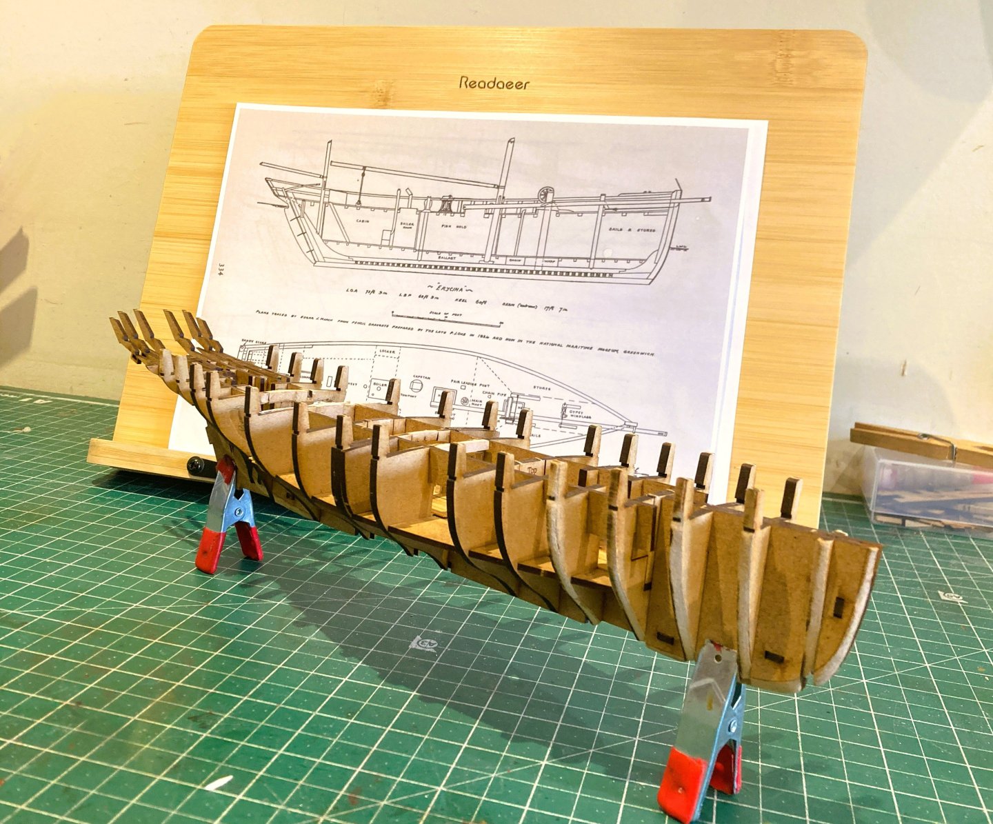
Hi Chris, I tend to choose kits where I have additional information; in the case of Erycina I have the internal layouts drawn by Edgar March, and a wealth of given sizes and rigging detail, contained in his book Sailing Trawlers. I used his companion book Sailing Drifters when I converted the Zulu kit to Muirneag. I then look at the kit and decide where I can enhance the detail which often develops organically. I do draw things out to scale where needed, and with deck cut-outs I use copies of the kit decks to work the final arrangement. I suppose after many years of messing around with kits I have the confidence to chop them around, but this is becoming increasingly less necessary with Vanguard kits as Chris develops more and more lower deck detail and associated fittings. Regards, B.E.
-
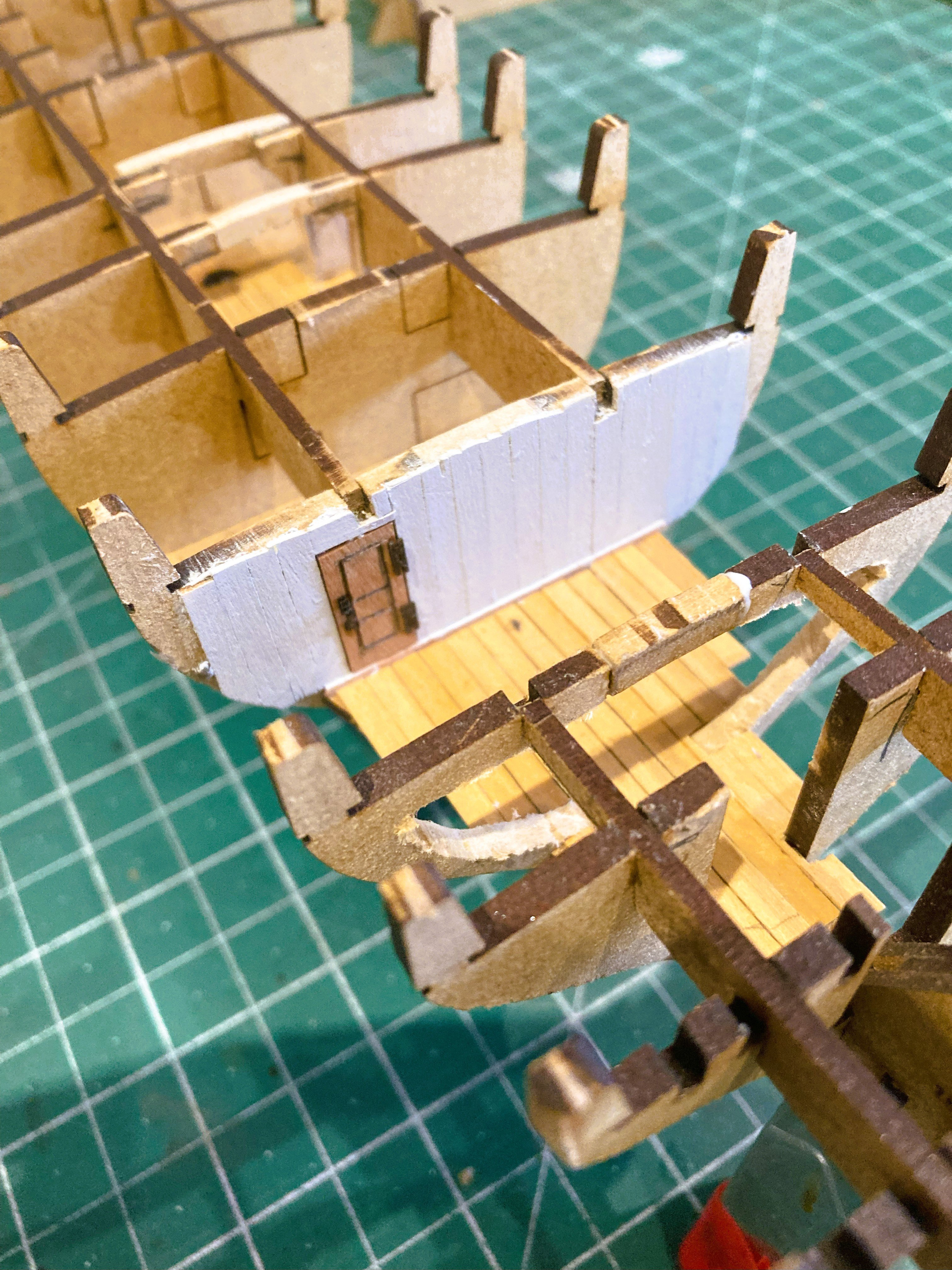
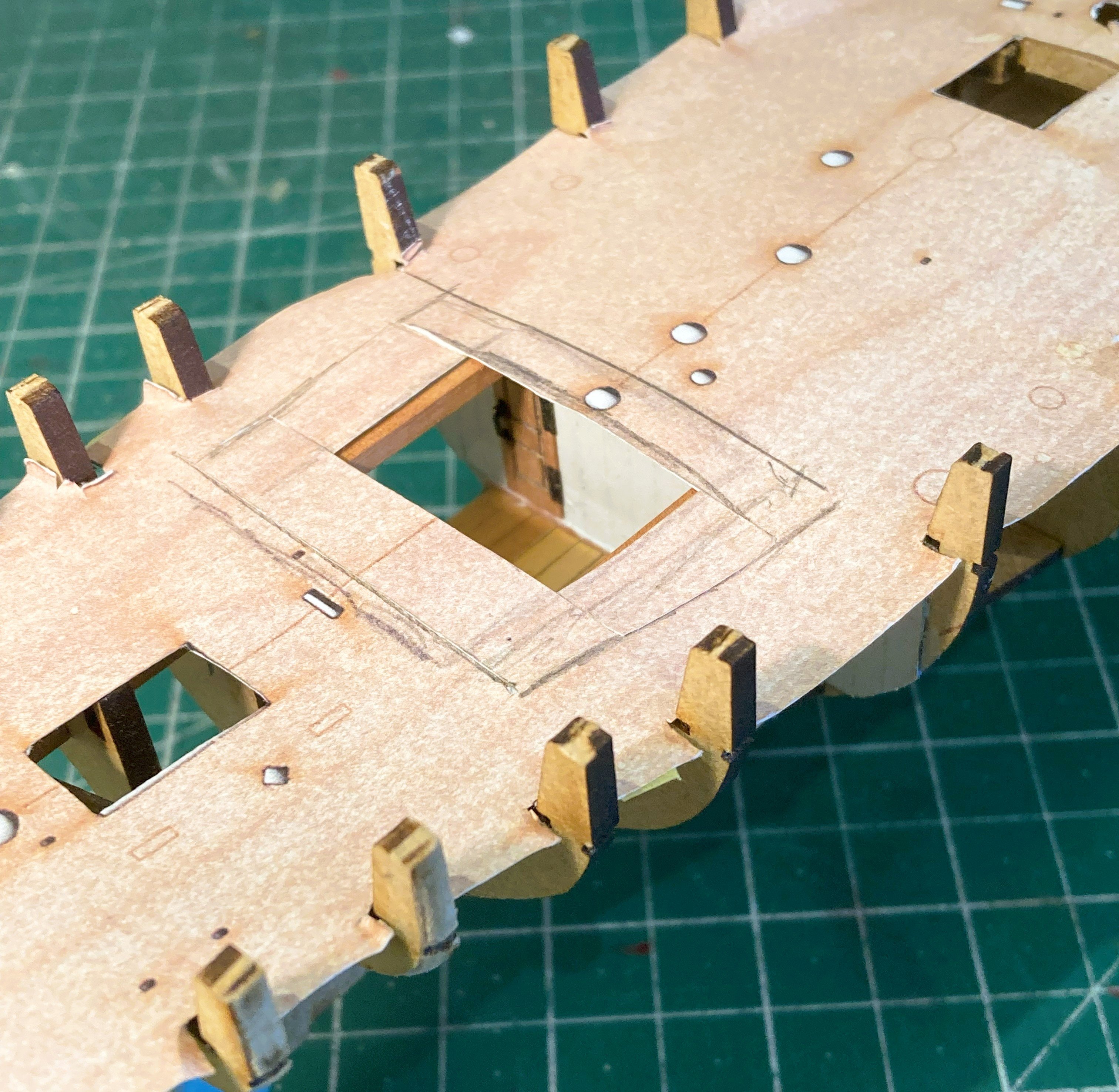
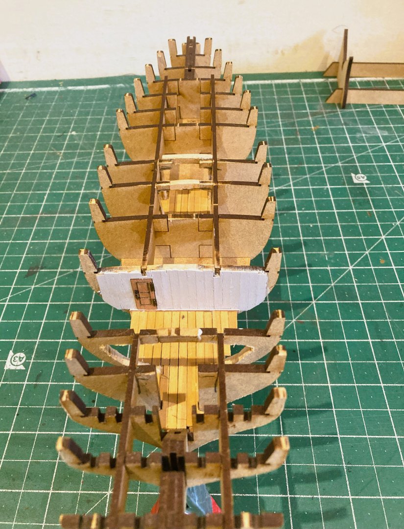
Thankyou Trevor, makes a lot of sense.👍 Post 2 Stern cabin area My idea is to fit out the cabin, certainly with the iron stove which will connect to the flue pipe emerging thro’ the deck, and maybe with other fittings as space allows. A section of deck will be left unplanked above the cabin. Modifying the cabin area is tricky, partly because work on Bulkhead 12 is more extensive, and because it proved too difficult to remove for shaping without risking damage and therefore had to be modified insitu. The filler pieces between the bulkheads prevented removal. Bulkhead 11 is closed off as this forms the partition between the cabin and the Boiler room. Bulkhead 12 bears the brunt of modification with large sections removed to create frames and beams. Tricky to get at to shape and sand. 5552a In this area the longitudinal bracing patterns are removed and replaced with Pear carlings. 5553a Bulkhead 11 is boarded using Boxwood strip and Whitewashed. A doorway leads to the Boiler room and the door is created from Boxwood strip and decorated with Syren hinges and Handle. 5554a 5557a The cabin deck area is planked with Boxwood strip. 5559a Similarly, the Fish hold is decked out using Boxwood strip. 5565a A paper deck print is used to determine the viewable area. Still work in progress, but you get the idea. B.E. 31/08/2025


-
Thank you Ron 👍 @ Palmerit - I hope to do a little more than that.🙂 Cheers, B.E.
-
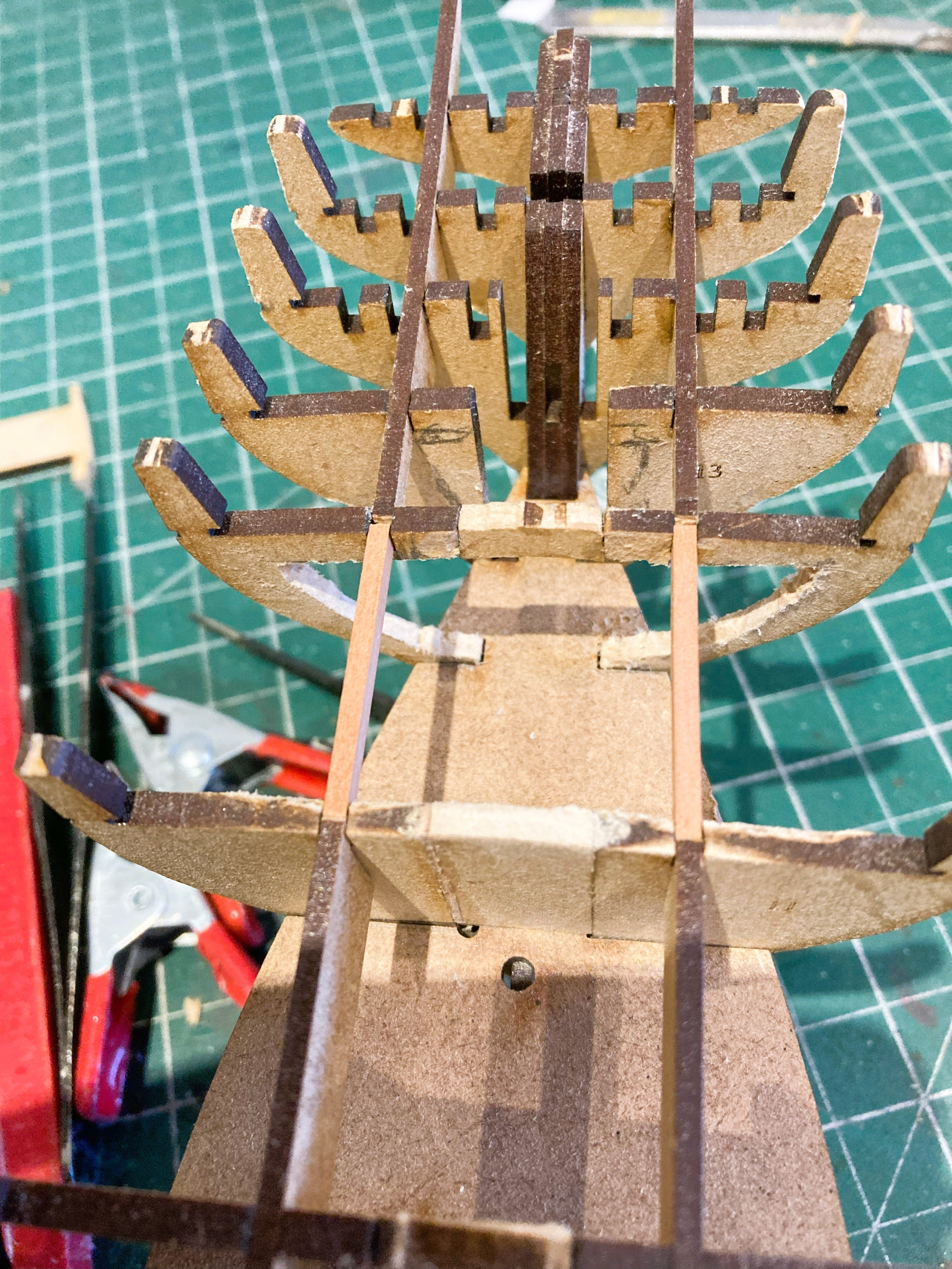
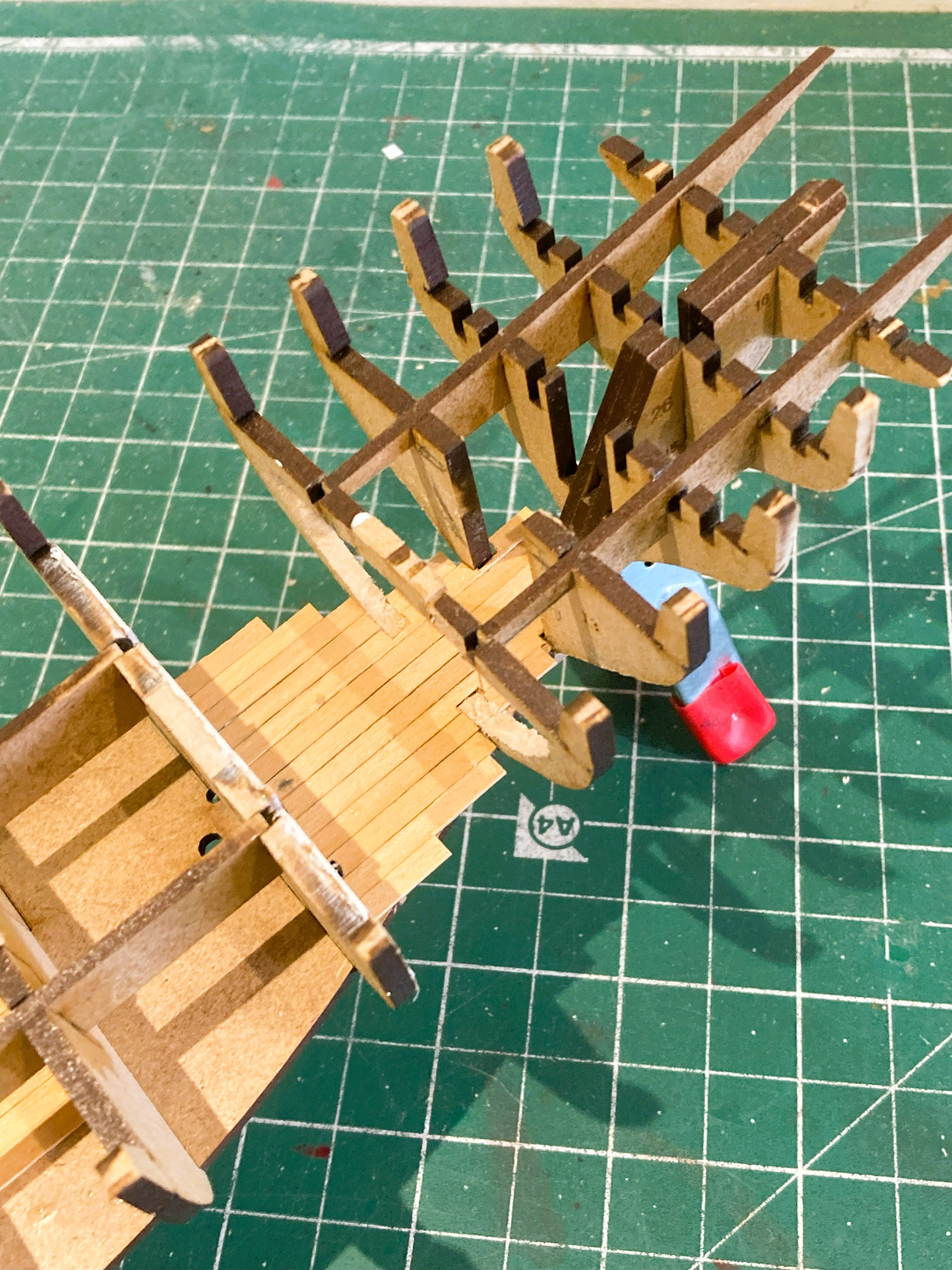
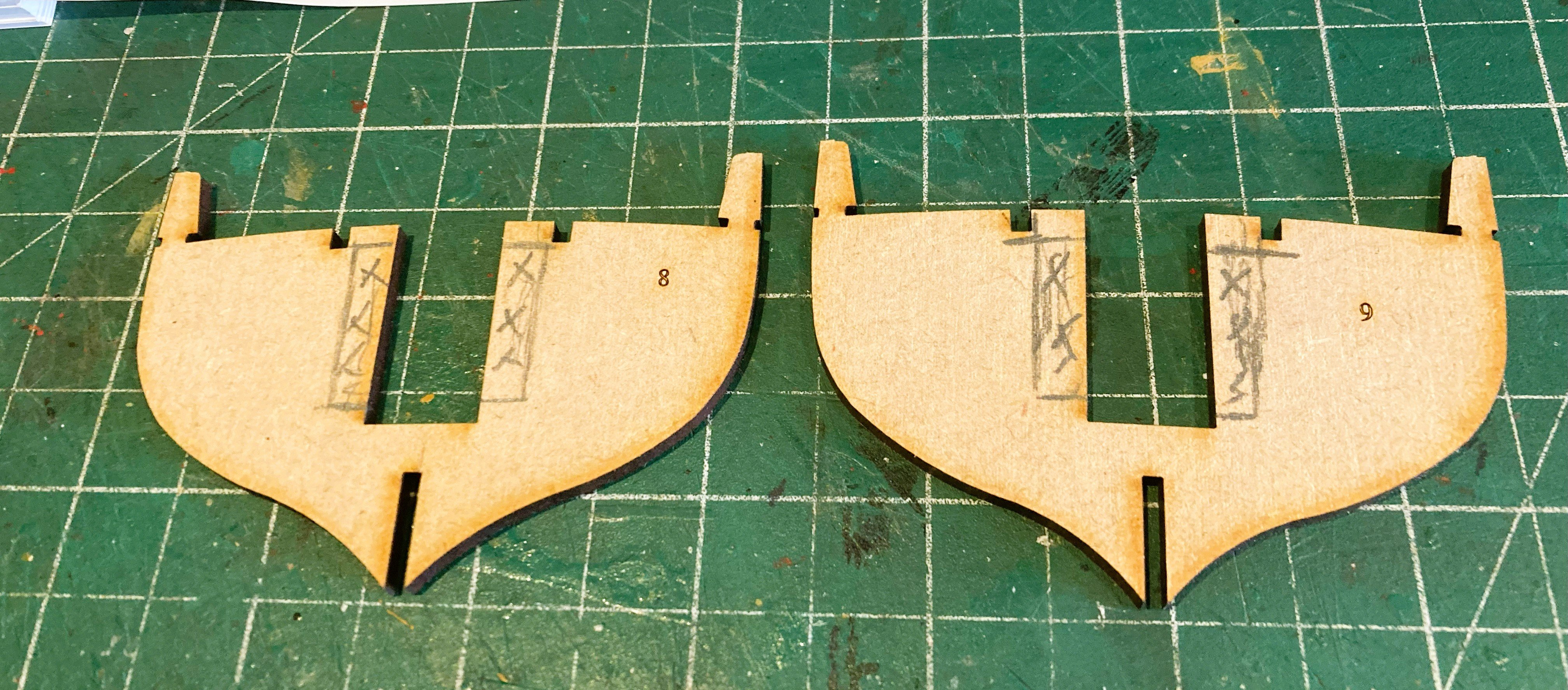
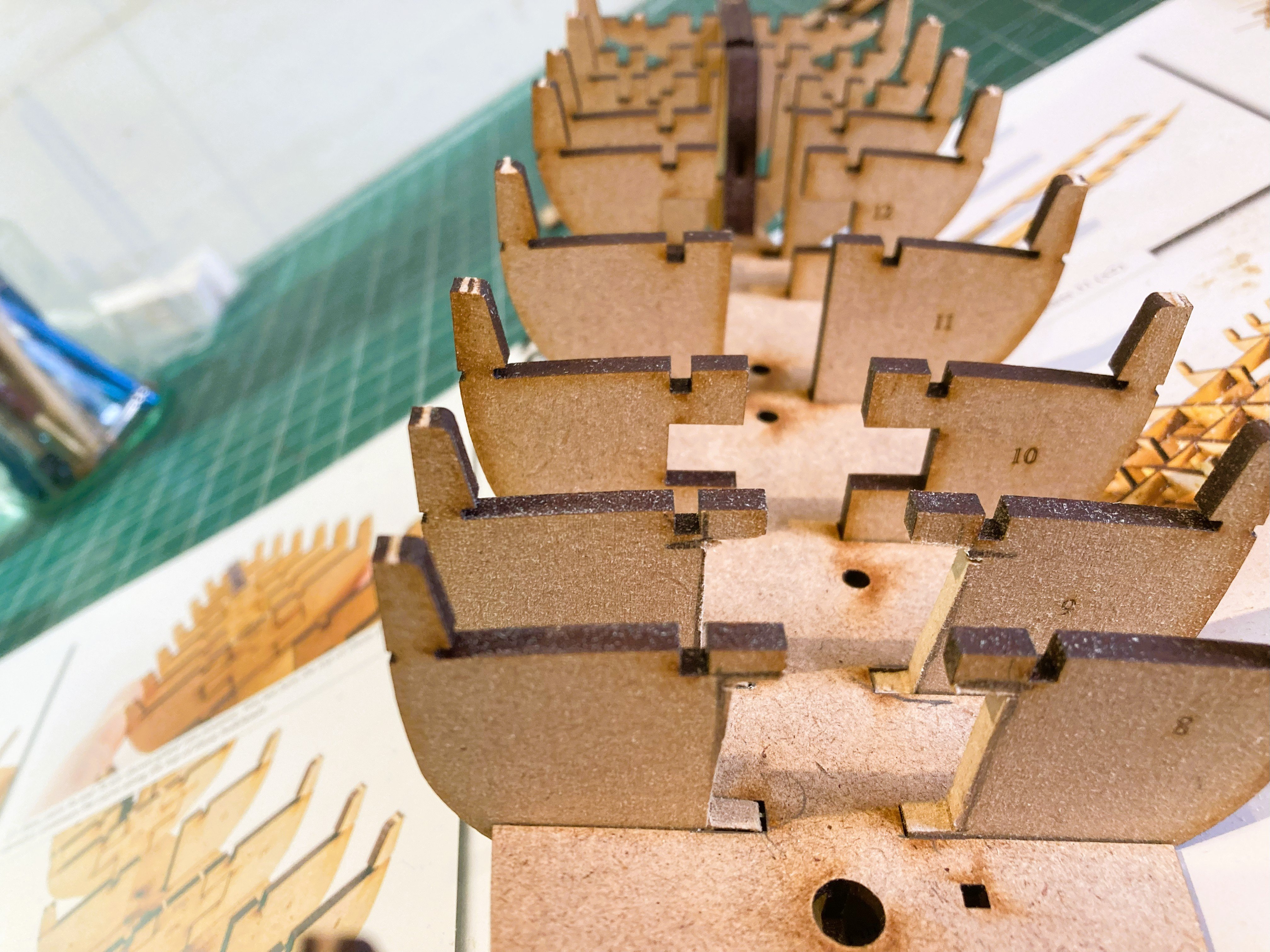
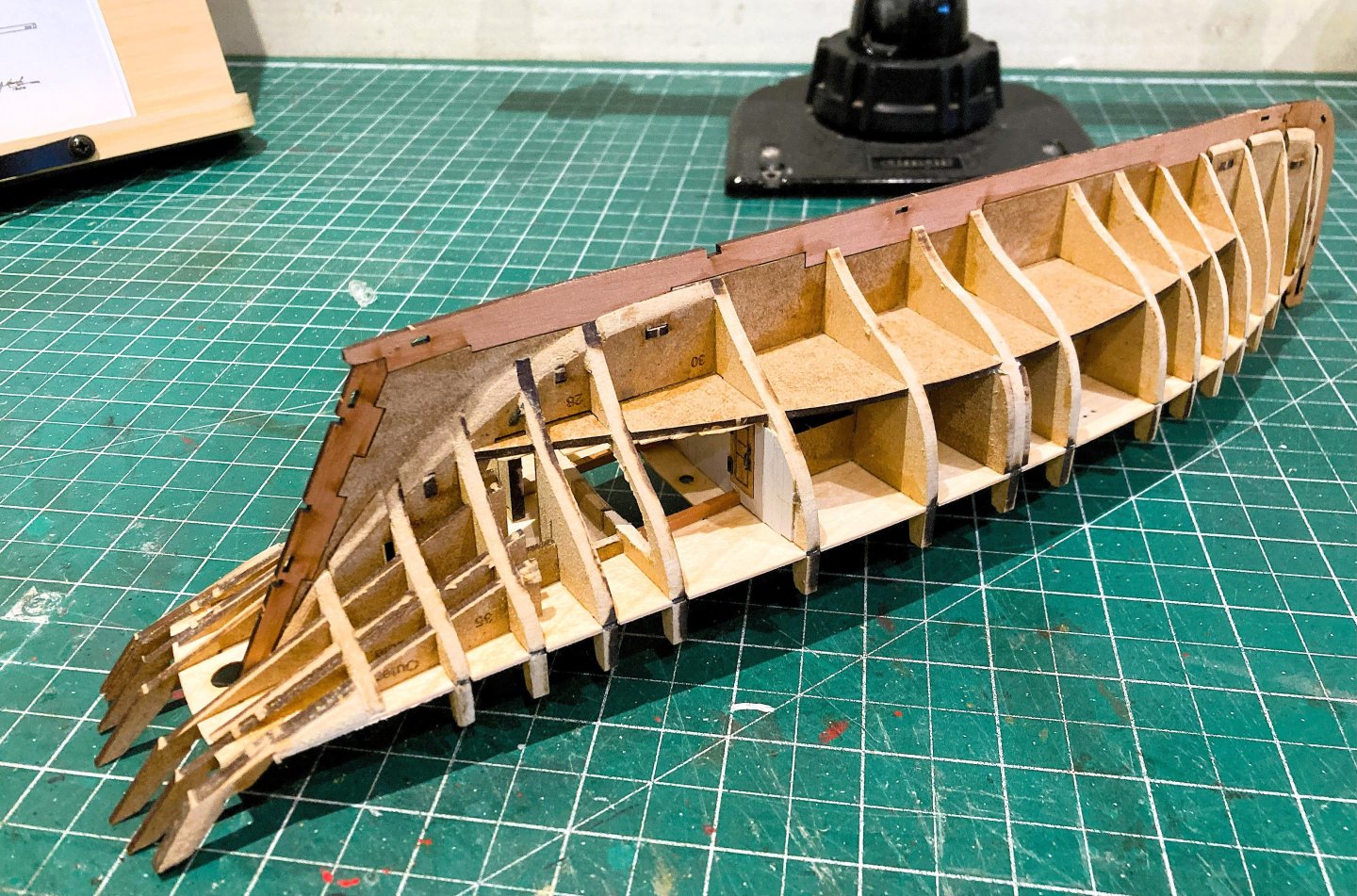
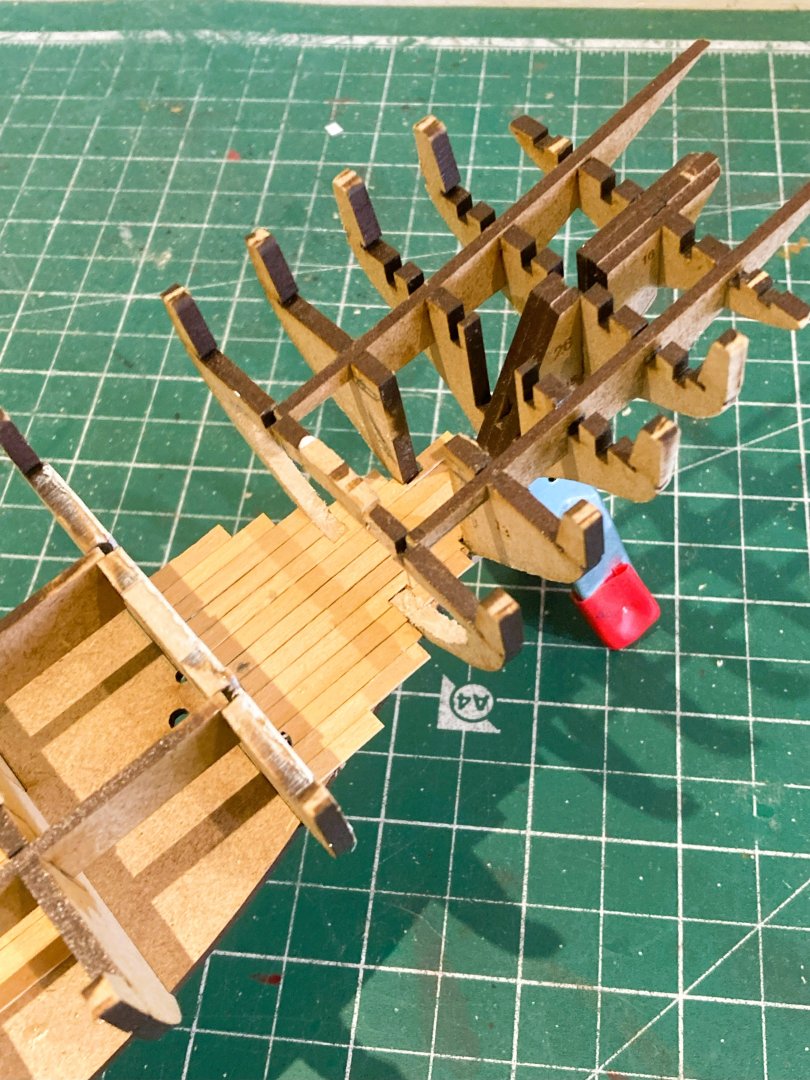
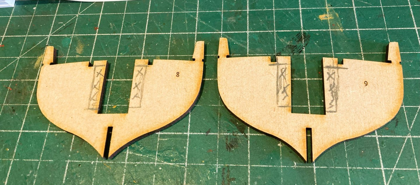
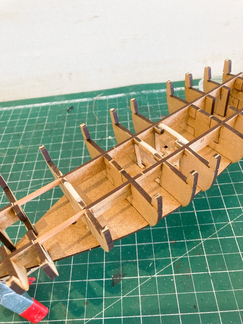
Post One Early stages The early stages of construction are just as we have come to expect from Vanguard. 5534a Rapid early progress with glueless assembly of perfectly fitting parts. That is unless you decide to open up the lower deck areas of the Fish hold and the cabin space. 5537a This involves some modification to the Bulkheads 8 and 9 ( in the case of the fish hold, and Bulkheads 12 and 13 in the case of the cabin area. 5539a 5540a Bulkheads 8 and 9 modified to give a clear space below the Main Hatch to the Fish hold. 5547a Faux deck beams are added but won’t be seen. 5548a I was quite surprised by the small main hatch on Erycina, Barely 3’ 6”(L) X 3’.0 (W). Seems hardly practical on a fishing boat, and miniscule compared to the cavernous hatchways on the Fifie and Zulu boats. She is however, quite a bit smaller than either Fifie or Zulu. I do like to have some open hatchways, gives depth to a model and at least an impression of more there than there is. The next stage is modifying the Cabin area. B.E. 30/08/2024


-
I can't see much difference in terms of construction between Zulu, which I built as Muirneag, and the Erycina; both have two masts and similar hull shapes. Erycina has shrouds and ratlines, and a slightly more complex sail arrangement, which possibly accounts for the different Vanguard rating. They are both excellent subjects for those new to ship modelling, and make very attractive models. You are doing a fine job with your Ranger build. 👍 B.E.
-
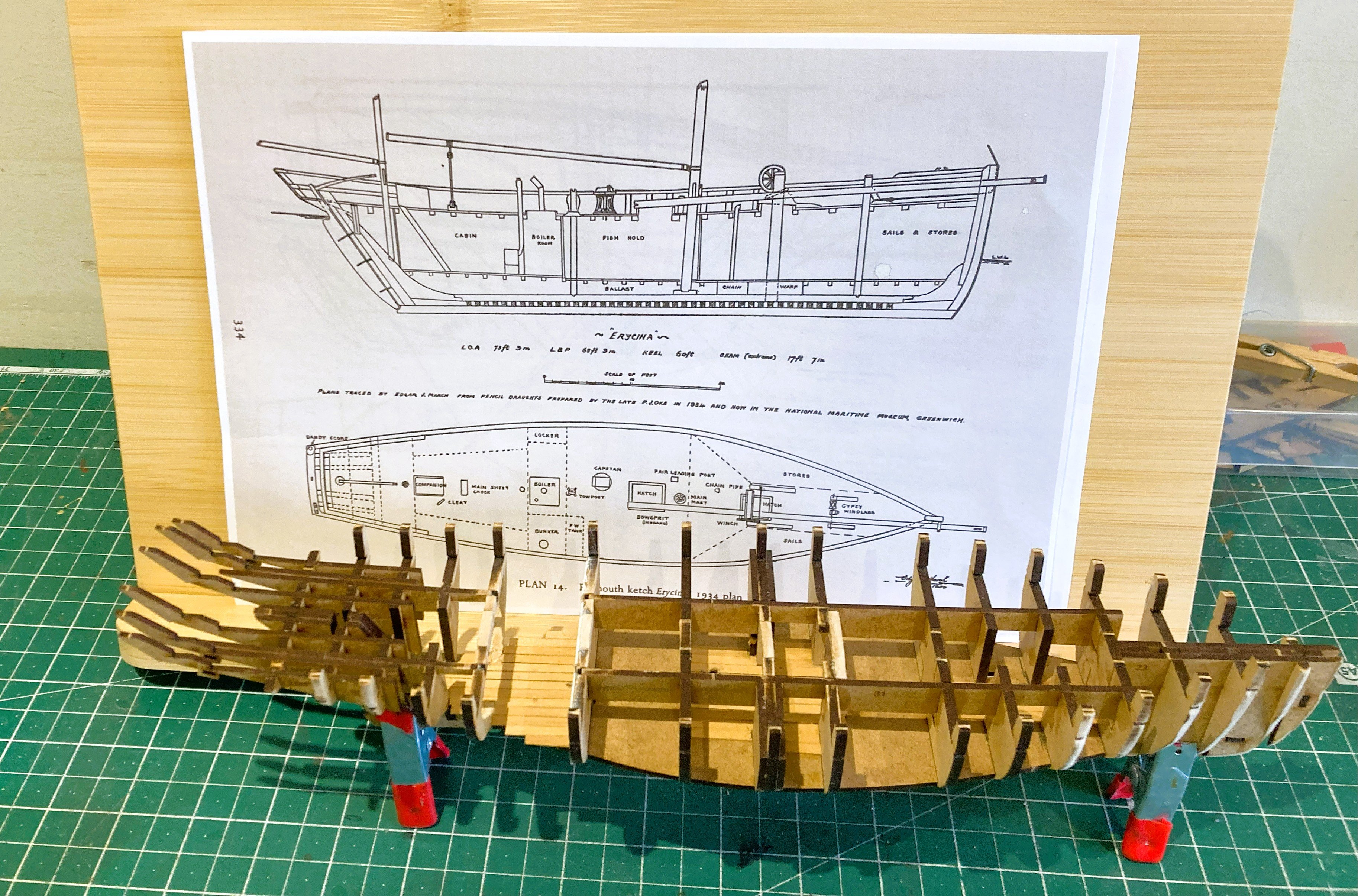
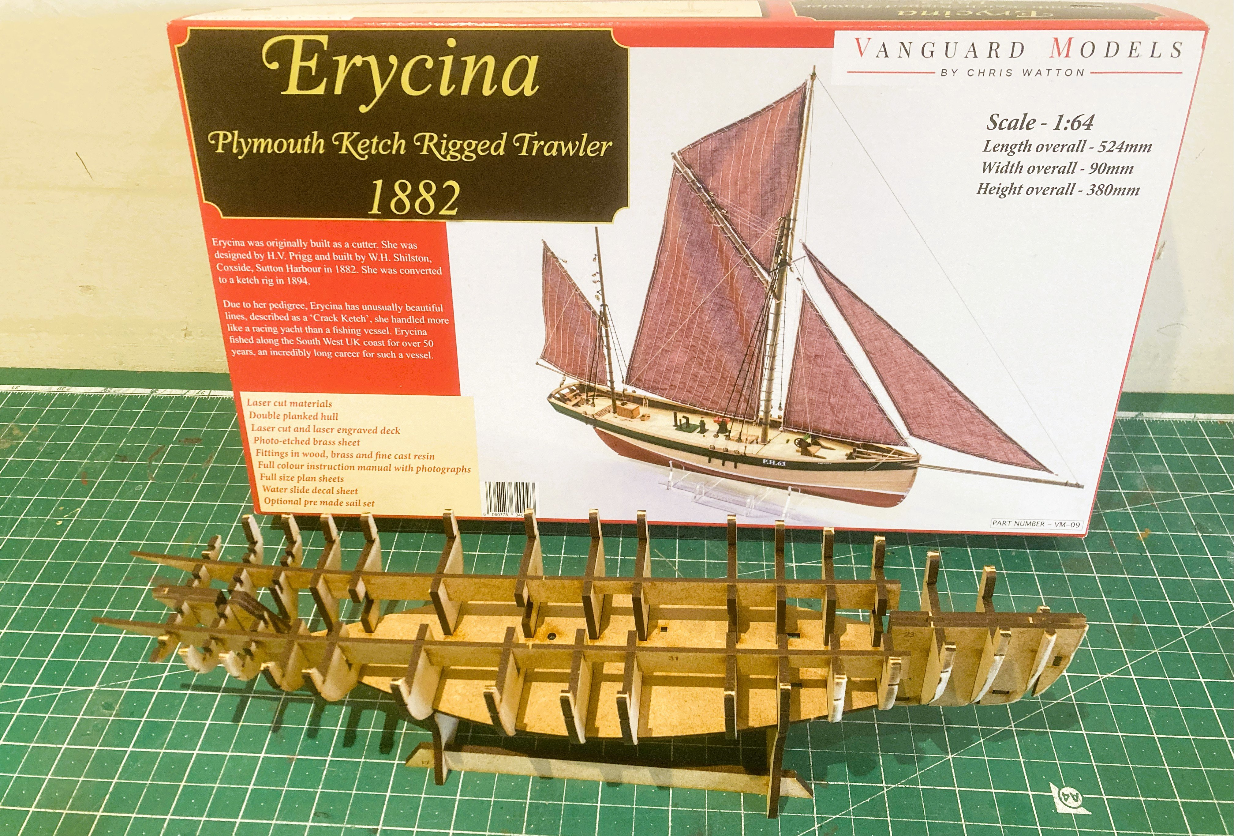
Erycina - Ketch rigged Plymouth Trawler 1882. I’ve had this kit for a while, and with nothing specific in the immediate offing it will give me hopefully a no stress easy build of this pretty little fishing vessel to complement my Fifie and Zulu builds. I was attracted to this boat by its sleek lines and interesting sail plan. Given the open deck and Fore and aft rigging it will be fairly easy to clean, and casing will not be required. It is also a model that will fit in a fairly small space. My interest is also piqued given additional detailing for Erycina is provided in the book Sailing Trawlers by Edgar J. March I can see an opportunity to indulge myself with a little off-piste detailing work. On with the show. B.E. 27/08/2025
-
The Jotika/Caldercraft Surprise sadly looks very clunky compared with the finely scaled details of present day Vanguard kits. Chris has done to the established ranges of many long established kit manufacturers, what HMS Warrior did to the Wooden sailing navy. B.E.
-
Thanks Chris, I can now see where the idea of a cill fixed carronade bed came from - Marquardt's drawings in the Frigate Surprise book. This was a bit of a 'surprise ' to me, as the only versions I recalled seeing are the 'inboard' and 'outboard' variants. Presumably you have tested a PolyBak structure is sufficiently robust to stand the odd inadvertent knock? Cheers, B.E.
-
I think she's a winner Chris.👏 Can you expand a little on the Carronade fixings, seems to be a bracket pinned thro' the cill, I'm not familiar with that arrangement. B.E.